28 Volt input – 15 aMp - · PDF fileDescription The FMCE-1528™ EMI filters are...
13
DESCRIPTION The FMCE-1528™ EMI filters are specifically designed to reduce the reflected input ripple current of Interpoint’s high frequency DC/DC converters. FMCE-1528 filters minimize electromagnetic interference (EMI) for the MFL, MOR, MTR, MHV, and MHF+ Series of converters. These filters are intended for use in 28 volt applications which must meet MIL-STD-461C CE03 and CS01 and/or MIL-STD-461D, E and F CE102 and CS101 levels of conducted emissions. One filter can be used with multiple converters up to the rated output current of the filter. INPUT RIPPLE AND EMI Switching DC/DC converters naturally generate two noise components on the power input line: differential noise and common mode noise. Input ripple current refers to both of these components. Differential noise occurs between the positive input and input common. Most Interpoint converters have an input filter that reduces differential noise which is sufficient for many appli- cations. Common mode noise occurs across stray capacitances between the converter’s power train components and the base- plate (bottom of the package) of the converter. Where low noise currents are required to meet MIL-STD-461, a power line filter is needed. The FMCE-1528 EMI power line filters reduce the common mode and differential noise generated by the converters. FMCE-1528 filters reduce input ripple current by as much as 70 dB at 500 kHz and 1 MHz when used in conjunction with Interpoint’s DC/DC converters. Place the filter as close as possible to the converter for optimum performance. The baseplates of the filter and the converter should be connected with the shortest and widest possible conductors. TRANSIENTS A transient of -0.5 to +80 volts (0.5 ohm source impedance) will not damage the filter but will be passed on to the converter: OPERATION OVER TEMPERATURE The FMCE-1528 Series filters are rated for full power opera- tion from -55°C to +125°C case temperature. Current is derated linearly to 80% at +135°C case temperature. INSERTION LOSS The maximum dc insertion loss at full load and nominal input voltage represents a power loss of less than 4%. PACKAGING FMCE-1528 filters are sealed in metal hermetic side-leaded packages. See cases U, V, W, Y, and Z. FEATURES Attenuation to 70 dB at 500 kHz, typical Operating temperature -55° to +125°C • Nominal 28 V input, -0.5 to 50 V operation • Transient rating -0.5 to 80 V for 1 second • Up to 15 A throughput current over the • full input voltage range of -0.5 to 50 V Compliant to • MIL-STD-461C,CE03 - MIL-STD-461D, E and F CE102 - MIL-STD-461C CS01 - MIL-STD-461D, E and F CS101 - Compatible with MIL-STD-704 A-E 28 VDC power bus • INPUT VOLTAGE AND CURRENT Input (V) 28 Current (A) 15 Crane Aerospace & Electronics Power Solutions FMCE-1528 EMI Input Filters Crane Aerospace & Electronics Electronics Group (Interpoint Brand) PO Box 97005 • Redmond WA 98073-9705 425.882.3100 • [email protected] www.interpoint.com Page 1 of 13 FMCE-1528 Rev E - 20100615 28 VOLT INPUT – 15 AMP
Transcript of 28 Volt input – 15 aMp - · PDF fileDescription The FMCE-1528™ EMI filters are...

DescriptionThe FMCE-1528™ EMI filters are specifically designed to reduce the reflected input ripple current of Interpoint’s high frequency DC/DC converters. FMCE-1528 filters minimize electromagnetic interference (EMI) for the MFL, MOR, MTR, MHV, and MHF+ Series of converters. These filters are intended for use in 28 volt applications which must meet MIL-STD-461C CE03 and CS01 and/or MIL-STD-461D, E and F CE102 and CS101 levels of conducted emissions. One filter can be used with multiple converters up to the rated output current of the filter.
Input RIpple and eMISwitching DC/DC converters naturally generate two noise components on the power input line: differential noise and common mode noise. Input ripple current refers to both of these components. Differential noise occurs between the positive input and input common. Most Interpoint converters have an input filter that reduces differential noise which is sufficient for many appli-cations. Common mode noise occurs across stray capacitances between the converter’s power train components and the base-plate (bottom of the package) of the converter.
Where low noise currents are required to meet MIL-STD-461, a power line filter is needed. The FMCE-1528 EMI power line filters reduce the common mode and differential noise generated by the converters. FMCE-1528 filters reduce input ripple current by as much as 70 dB at 500 kHz and 1 MHz when used in conjunction with Interpoint’s DC/DC converters.
Place the filter as close as possible to the converter for optimum performance. The baseplates of the filter and the converter should be connected with the shortest and widest possible conductors.
tRansIentsA transient of -0.5 to +80 volts (0.5 ohm source impedance) will not damage the filter but will be passed on to the converter:
OpeRatIOn OveR teMpeRatuReThe FMCE-1528 Series filters are rated for full power opera-tion from -55°C to +125°C case temperature. Current is derated linearly to 80% at +135°C case temperature.
InseRtIOn lOssThe maximum dc insertion loss at full load and nominal input voltage represents a power loss of less than 4%.
packagIngFMCE-1528 filters are sealed in metal hermetic side-leaded packages. See cases U, V, W, Y, and Z.
Featuresattenuation to 70 dB at 500 kHz, typical
Operating temperature -55° to +125°C•Nominal 28 V input, -0.5 to 50 V operation•Transient rating -0.5 to 80 V for 1 second•Up to 15 A throughput current over the •full input voltage range of -0.5 to 50 VCompliant to •
MIL-STD-461C,CE03 -MIL-STD-461D, E and F CE102 -MIL-STD-461C CS01 -MIL-STD-461D, E and F CS101 -
Compatible with MIL-STD-704 A-E 28 VDC power bus•
Input vOltage and cuRRent
Input (V)28
Current (A)15
Crane Aerospace & Electronics Power Solutions
FMce-1528 eMi input Filters
Crane Aerospace & ElectronicsElectronics Group (Interpoint Brand)POBox97005•RedmondWA98073-9705425.882.3100•[email protected]
Page 1 of 13FMCE-1528 Rev E - 20100615
28 Volt input – 15 aMp
Operating COnditiOns and CharaCteristiCs
input Voltage rangeContinuous -0.5 to 50 VDC•Transient -0.5 to 80 V for 1 second•
lead soldering temperature (10 sec per lead) 300°C•
storage temperature range (case) -65°C to +150°C•
case operating temperature (tc)-55°C to +125°C full power•-55°C to +135°C absolute•
Derating input/output currentLinearly from 100% at 125°C to 80% at 135° C•
isolation (tc = 25°c)100 megohm minimum at 500 VDC•Any pin to case•
electrostatic Discharge (esD) sensitivity per Mil-prF-38534Classification 3B, 8000 V•
meChaniCal and envirOnmental
size (maximum)Case U •3.005 x 1.505 x 0.400 inches (76.33 x 38.23 x 10.16 mm) The image on page one shows Case U (flanged, short leads) Also available: •
Flanged: leads bent down (case V) ‣Tabbed: leads bent up (case W) ‣Tabbed: short leads (case Y) ‣Tabbed: leads bent down (case Z) ‣ See cases U, V, W, Y, and Z for dimensions and options ‣
Weight (maximum)86 grams all cases (U, V, W, Y, and Z)•
screeningThe FMCE-1528 EMI Input filter offers Standard, /ES or 883, Class H, QML screening. See Screening Tables 1 and 2 for more information.
PositiveInput
InputCommon
PositiveOutput
OutputCommon
T1 T2
L1
R1
R2
FIguRe 2: scheMatIc FMce-1528
+Vin +Vout
InputCommon
OutputCommon
Case R L
R L
EMI FILTER DC/DC CONVERTER+Vin +Vout
InputCommon
OutputCommon
Case
Chassisground
Multiple unitsallowed up torated output
current of filter
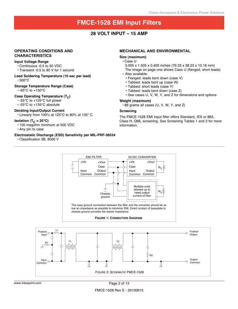
Figure 1: ConneCtion Diagram
The case ground connection between the filter and the converter should be aslow an impedance as possible to minimize EMI. Direct contact of baseplate tochassis ground provides the lowest impedance.
Crane Aerospace & Electronics Power Solutions
www.interpoint.com Page 2 of 13
FMce-1528 eMi input Filters28 Volt input – 15 aMp
FMCE-1528 Rev E - 20100615

Angled corner and cover marking indicate pin one for cases U and V. Cover marking indicates pin one for cases W, Y and Z.
TOP VIEWU Case1
2
3
4
5
6
12
11
10
9
8
7
pin out
Outline shown is case U, pin out is the samefor all cases. See cases U, V, W, Y, and Z for dimensions.
Notes1. All pins must be connected.2. The baseplate is the only case ground connection and
should directly contact chassis ground.
FIguRe 3: pIn Out
pin outpin Designation
1, 2, 3 Positive Input4, 5, 6 Input Common7, 8, 9 Output Common
10, 11, 12 Positive OutputBottom of
case Case Ground
Crane Aerospace & Electronics Power Solutions
www.interpoint.com Page 3 of 13
FMce-1528 eMi input Filters28 Volt input – 15 aMp
FMCE-1528 Rev E - 20100615
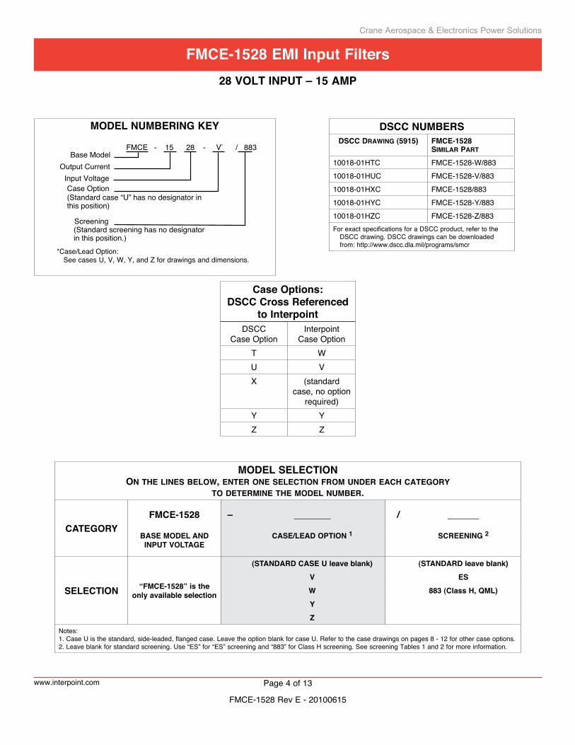
MoDel nuMBering key
FMCE - 15 28 - V* / 883 Base Model
Output Current Input Voltage
Screening(Standard screening has no designatorin this position.)
Case Option(Standard case “U” has no designator inthis position)
MoDel selection on the lines below, enter one seleCtion From unDer eaCh Category
to Determine the moDel number.
categoryFMce-1528 – _______ / ______
Base MoDel anD input Voltage
case/leaD option 1 screening 2
selection “FMce-1528” is the only available selection
(stanDarD case u leave blank) (stanDarD leave blank)
V es
W 883 (class H, QMl)yZ
Notes:1. Case U is the standard, side-leaded, flanged case. Leave the option blank for case U. Refer to the case drawings on pages 8 - 12 for other case options.2. Leave blank for standard screening. Use “ES” for “ES” screening and “883” for Class H screening. See screening Tables 1 and 2 for more information.
Dscc nuMBersDsCC Drawing (5915) FmCe-1528
similar Part
10018-01HTC FMCE-1528-W/88310018-01HUC FMCE-1528-V/88310018-01HXC FMCE-1528/88310018-01HYC FMCE-1528-Y/88310018-01HZC FMCE-1528-Z/883For exact specifications for a DSCC product, refer to the
DSCC drawing. DSCC drawings can be downloaded from: http://www.dscc.dla.mil/programs/smcr
*Case/Lead Option: See cases U, V, W, Y, and Z for drawings and dimensions.
case options: Dscc cross referenced
to interpoint DSCC
Case OptionInterpoint
Case OptionT WU VX (standard
case, no option required)
Y YZ Z
Crane Aerospace & Electronics Power Solutions
www.interpoint.com Page 4 of 13
FMce-1528 eMi input Filters28 Volt input – 15 aMp
FMCE-1528 Rev E - 20100615

Electrical Characteristics: -55° to +125°C TC, nominal Vin, unless otherwise specified.
Note1. guaranteed by design, not tested.2. 0.5 ohm source impedance3. Typical applications result in Vout within 4% of Vin.
MODEL FMCE-1528
paRaMeteR cOndItIOns MIN TYP MAX unItsInput vOltage cOntInuOus -0.5 28 50 VDC
tRansIent, 1 sec 1, 2 -0.5 — 80 VnOIse ReJectIOn 500 khz 60 70 — dB
1 Mhz 60 70 —dc ResIstance (Rdc)at MaXIMuM cuRRent
tc = 25°c — — 0.06 Ωtc = 125°c 1 — — 0.07
capacItance anY pIn tO casetc = 25°c 50,000 60,000 70,000 pF
Output vOltage 3 steadY state VOUT = VIN - IIN (RDC) VDC
Output cuRRent steadY statevIn = -0.5 - 50 vdc — — 15 A
pOWeR dIssIpatIOnat MaXIMuM cuRRent 1
tc = 25°c — — 13.5 Wtc = 125°c — — 15.75
Crane Aerospace & Electronics Power Solutions
www.interpoint.com Page 5 of 13
FMce-1528 eMi input Filters28 Volt input – 15 aMp
FMCE-1528 Rev E - 20100615
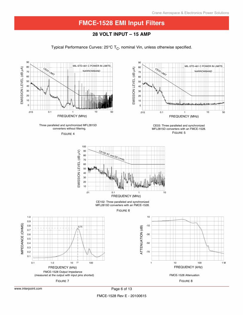
Typical Performance Curves: 25°C TC, nominal Vin, unless otherwise specified.
FIguRe 4
FIguRe 6
Three paralleled and synchronized MFL2815D converters without filtering.
FIguRe 5
FIguRe 7 FIguRe 8
CE03: Three paralleled and synchronizedMFL2815D converters with an FMCE-1528.
CE102: Three paralleled and synchronizedMFL2815D converters with an FMCE-1528.
FMCE-1528 Output Impedance (measured at the output with input pins shorted) FMCE-1528 Attenuation
EMIS
SIO
N L
EVEL
(dB
µA)
FREQUENCY (MHz)
CE03 LIMITNARROWBAND
MIL-STD-461 C POWER IN LIMITS
.015 0.1 1 10 50
90
80
70
60
50
40
30
20
0
10
EMIS
SIO
N L
EVEL
(dB
µV) CE102 AC and DC Limits
FREQUENCY (MHz)0.1 1 10.01
90
100
80
70
60
50
40
30
20
10
EMIS
SIO
N L
EVEL
(dB
µA)
FREQUENCY (MHz)
CE03 LIMITNARROWBAND
MIL-STD-461 C POWER IN LIMITS
.015 0.1 1 10 50
90
80
70
60
50
40
30
20
0
10
FREQUENCY (kHz)1.0 10
0.9
1.0
0.8
0.7
0.6
0.5
0.4
0.3
0.2
0.1
0.1 100
IMPE
DAN
CE
(OH
MS)
21
0.75
FREQUENCY (kHz)10 1001 1 M
ATTE
NU
ATIO
N (d
B)
10
-10
-30
-50
-70
Crane Aerospace & Electronics Power Solutions
www.interpoint.com Page 6 of 13
FMce-1528 eMi input Filters28 Volt input – 15 aMp
FMCE-1528 Rev E - 20100615

FIguRe 9: case u
Angled cornerindicates pin one.
1
2
3
4
5
6
12
11
10
9
8
7
0.00
00.
050
(1.2
7)
0.0000.120 (3.05)0.250 (6.35)
0.450 (11.43)
0.650 (16.51)
0.850 (21.59)
1.050 (26.67)
1.250 (31.75)1.380 (35.05)
1.505 (38.23) max.
0.00
00.
120
(3.0
5)0.
250
(6.3
5)
2.75
0 (6
9.85
)2.
880
(73.
15)
3.00
5 (7
6.33
) max
.
0.128 dia(3.25).
0.040 dia(1.02)
0.23 (5.8) Pin Length
0.40
0 (1
0.16
) max
.
0.22
0 (5
.59
TOP VIEW CASE U*Flanged case, short-leaded
Seam Seal
*Does not require designator in Case Option position of model number.
Case dimensions in inches (mm)Tolerance ±0.005 (0.13) for three decimal places ±0.01 (0.3) for two decimal places unless otherwise specified
CAUTIONHeat from reflow or wave soldering may damage the device. Solder pins individually with heat application not exceeding 300°C for 10 seconds per pin.
MaterialsHeader Cold Rolled Steel/Nickel/GoldCover Kovar/NickelPins #52 alloy/Gold, compression glass seal Seal Hole: 0.100 ±0.002 (2.54 ±0.05)
Case U, Rev F, 20100503
Crane Aerospace & Electronics Power Solutions
www.interpoint.com Page 7 of 13
FMce-1528 eMi input Filters – cases28 Volt input – 15 aMp
FMCE-1528 Rev E - 20100615
0.00
0
0.22
0 (5
.59)
0.05
0 (1
.27)
0.40
0 (1
0.16
) max
ref:
0.25
0 ±0
.050
(6.3
5 ±1
.27)
ref:
0.22
5 (5
.72
3.45 (87.6) Reference(lead center to lead center)
0.000
0.120 (3.05)0.250 (6.35)
0.450 (11.43)
0.650 (16.51)
0.850 (21.59)
1.050 (26.67)
1.250 (31.75)1.380 (35.05)
0.00
00.
120
(3.0
5)0.
250
±0.0
10 (6
.35
±0.3
)
2.75
0 (6
9.85
)2.
880
(73.
15)
0.128 dia (3.25)
0.040 dia(1.02)
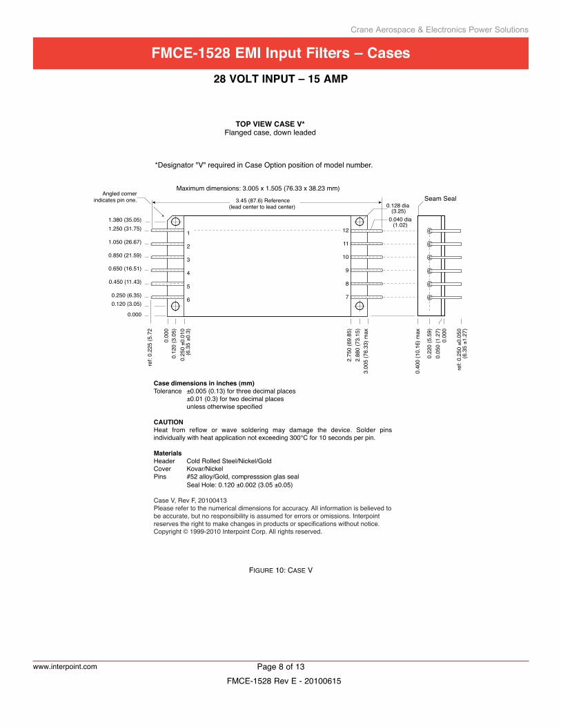
TOP VIEW CASE V*Flanged case, down leaded
*Designator "V" required in Case Option position of model number.
1
2
3
4
5
6
12
11
10
9
8
7
Maximum dimensions: 3.005 x 1.505 (76.33 x 38.23 mm)Angled corner
indicates pin one.
3.00
5 (7
6.33
) max
Case dimensions in inches (mm)Tolerance ±0.005 (0.13) for three decimal places ±0.01 (0.3) for two decimal places unless otherwise specified
CAUTIONHeat from reflow or wave soldering may damage the device. Solder pins individually with heat application not exceeding 300°C for 10 seconds per pin.
MaterialsHeader Cold Rolled Steel/Nickel/GoldCover Kovar/NickelPins #52 alloy/Gold, compresssion glas seal Seal Hole: 0.120 ±0.002 (3.05 ±0.05)
Case V, Rev F, 20100413Please refer to the numerical dimensions for accuracy. All information is believed to be accurate, but no responsibility is assumed for errors or omissions. Interpoint reserves the right to make changes in products or specifications without notice.Copyright © 1999-2010 Interpoint Corp. All rights reserved.
Seam Seal
FIguRe 10: case v
Crane Aerospace & Electronics Power Solutions
www.interpoint.com Page 8 of 13
FMce-1528 eMi input Filters – cases28 Volt input – 15 aMp
FMCE-1528 Rev E - 20100615
1
2
3
4
5
6
12
11
10
9
8
7
0.040 dia(1.02)
0.250 (6.35) Typ.
0.125 (3.18)
0.375(9.53)
0.575(14.61)
0.775(19.69)
0.975(24.77)
1.175(29.85
1.375(34.93)
1.625(41.28)
2.12
5 (5
3.98
)
0.37
5 (9
.53)
0.140 dia(3.56)
0.00
0
1.75
0 (4
4.45
)
0.000
0.250 (6.35) Typ.
1.45
0 (3
6.83
)
0.30
0 (7
.62)
1.750 (44.45)
2.000 (50.80)
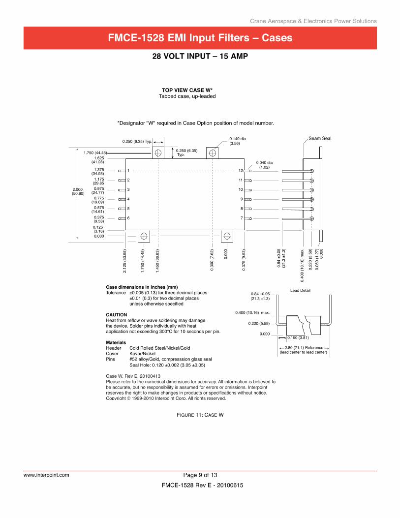
TOP VIEW CASE W*Tabbed case, up-leaded
0.00
0
0.22
0 (5
.59)
0.05
0 (1
.27)
0.40
0 (1
0.16
) max
.
0.000
0.220 (5.59)
0.400 (10.16) max.
0.84 ±0.05(21.3 ±1.3)
0.84
±0.
05(2
1.3
±1.3
)
0.150 (3.81)
Lead Detail
2.80 (71.1) Reference(lead center to lead center)
*Designator "W" required in Case Option position of model number.
Case dimensions in inches (mm)Tolerance ±0.005 (0.13) for three decimal places ±0.01 (0.3) for two decimal places unless otherwise specified
CAUTIONHeat from reflow or wave soldering may damagethe device. Solder pins individually with heatapplication not exceeding 300°C for 10 seconds per pin.
MaterialsHeader Cold Rolled Steel/Nickel/GoldCover Kovar/NickelPins #52 alloy/Gold, compresssion glass seal Seal Hole: 0.120 ±0.002 (3.05 ±0.05)
Case W, Rev E, 20100413Please refer to the numerical dimensions for accuracy. All information is believed to be accurate, but no responsibility is assumed for errors or omissions. Interpoint reserves the right to make changes in products or specifications without notice.Copyright © 1999-2010 Interpoint Corp. All rights reserved.
Seam Seal
FIguRe 11: case W
Crane Aerospace & Electronics Power Solutions
www.interpoint.com Page 9 of 13
FMce-1528 eMi input Filters – cases28 Volt input – 15 aMp
FMCE-1528 Rev E - 20100615
0.250 (6.35) Typ.
0.125 (3.18)
0.375(9.53)
0.575(14.61)
0.775(19.69)
0.975(24.77)
1.175(29.85
1.375(34.93)
1.625(41.28)
2.12
5 (5
3.98
)
0.37
5 (9
.53)
0.140 dia(3.56)
0.00
0
1.75
0 (4
4.45
)
0.000
0.250 (6.35) Typ.
1.45
0 (3
6.83
)
0.30
0 (7
.62)
1.750 (44.45)
2.000 (50.80)
0.00
0
0.22
0 (5
.59)
0.05
0 (1
.27)
0.40
0 (1
0.16
) max
.
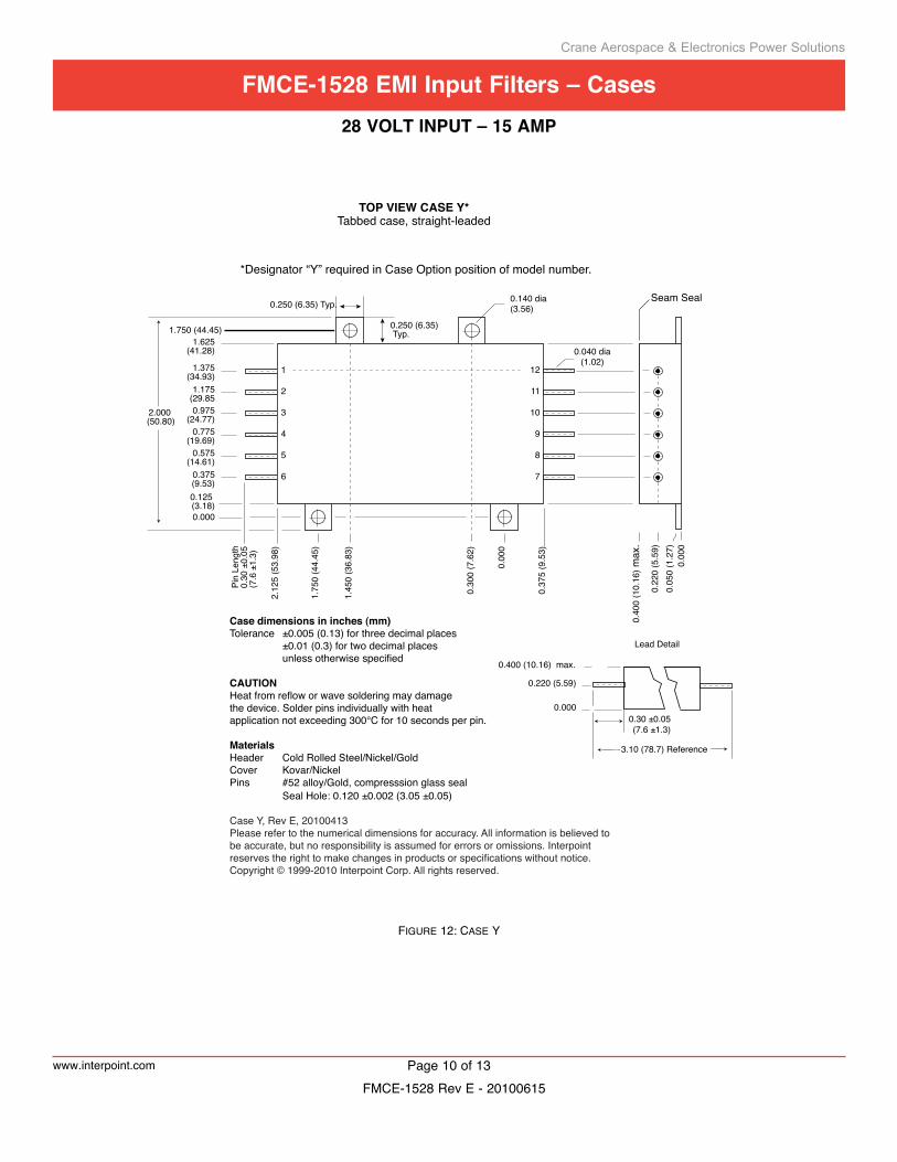
TOP VIEW CASE Y*Tabbed case, straight-leaded
0.000
0.220 (5.59)
0.400 (10.16) max.
0.30 ±0.05(7.6 ±1.3)
Lead Detail
Pin
Leng
th0.
30 ±
0.05
(7.6
±1.
3)
3.10 (78.7) Reference
0.040 dia(1.02)
1
2
3
4
5
6
12
11
10
9
8
7
*Designator “Y” required in Case Option position of model number.
Case dimensions in inches (mm)Tolerance ±0.005 (0.13) for three decimal places ±0.01 (0.3) for two decimal places unless otherwise specified
CAUTIONHeat from reflow or wave soldering may damagethe device. Solder pins individually with heatapplication not exceeding 300°C for 10 seconds per pin.
MaterialsHeader Cold Rolled Steel/Nickel/GoldCover Kovar/NickelPins #52 alloy/Gold, compresssion glass seal Seal Hole: 0.120 ±0.002 (3.05 ±0.05)
Case Y, Rev E, 20100413Please refer to the numerical dimensions for accuracy. All information is believed to be accurate, but no responsibility is assumed for errors or omissions. Interpoint reserves the right to make changes in products or specifications without notice.Copyright © 1999-2010 Interpoint Corp. All rights reserved.
Seam Seal
FIguRe 12: case Y
Crane Aerospace & Electronics Power Solutions
www.interpoint.com Page 10 of 13
FMce-1528 eMi input Filters – cases28 Volt input – 15 aMp
FMCE-1528 Rev E - 20100615
0.250 (6.35) Typ.
0.125 (3.18)
0.375(9.53)
0.575(14.61)
0.775(19.69)
0.975(24.77)
1.175(29.85
1.375(34.93)
1.625(41.28)
2.12
5 (5
3.98
)
0.37
5 (9
.53)
0.140 dia(3.56)
0.00
0
1.75
0 (4
4.45
)
0.000
0.250 (6.35) Typ.
1.45
0 (3
6.83
)
0.30
0 (7
.62)
1.750 (44.45)
2.000 (50.80)
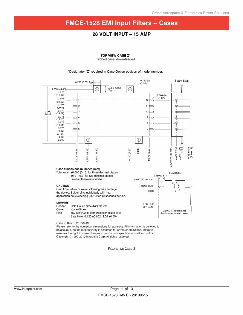
TOP VIEW CASE Z*Tabbed case, down-leaded
*Designator “Z” required in Case Option position of model number.
0.00
0
0.22
0 (5
.59)
0.05
0 (1
.27)
0.40
0 (1
0.16
) max
.
0.000
0.220 (5.59)
0.400 (10.16) max.
0.36 ±0.05(9.1±0.13)
0.150 (3.81)Lead Detail
2.80 (71.1) Reference(lead center to lead center)
0.36
±0.
05(9
.1±0
.13)
0.040 dia(1.02)
1
2
3
4
5
6
12
11
10
9
8
7
Case dimensions in inches (mm)Tolerance ±0.005 (0.13) for three decimal places ±0.01 (0.3) for two decimal places unless otherwise specified
CAUTIONHeat from reflow or wave soldering may damagethe device. Solder pins individually with heatapplication not exceeding 300°C for 10 seconds per pin.
MaterialsHeader Cold Rolled Steel/Nickel/GoldCover Kovar/NickelPins #52 alloy/Gold, compresssion glass seal Seal Hole: 0.120 ±0.002 (3.05 ±0.05)
Case Z, Rev E, 20100413Please refer to the numerical dimensions for accuracy. All information is believed to be accurate, but no responsibility is assumed for errors or omissions. Interpoint reserves the right to make changes in products or specifications without notice.Copyright © 1999-2010 Interpoint Corp. All rights reserved.
Seam Seal
FIguRe 13: case z
Crane Aerospace & Electronics Power Solutions
www.interpoint.com Page 11 of 13
FMce-1528 eMi input Filters – cases28 Volt input – 15 aMp
FMCE-1528 Rev E - 20100615
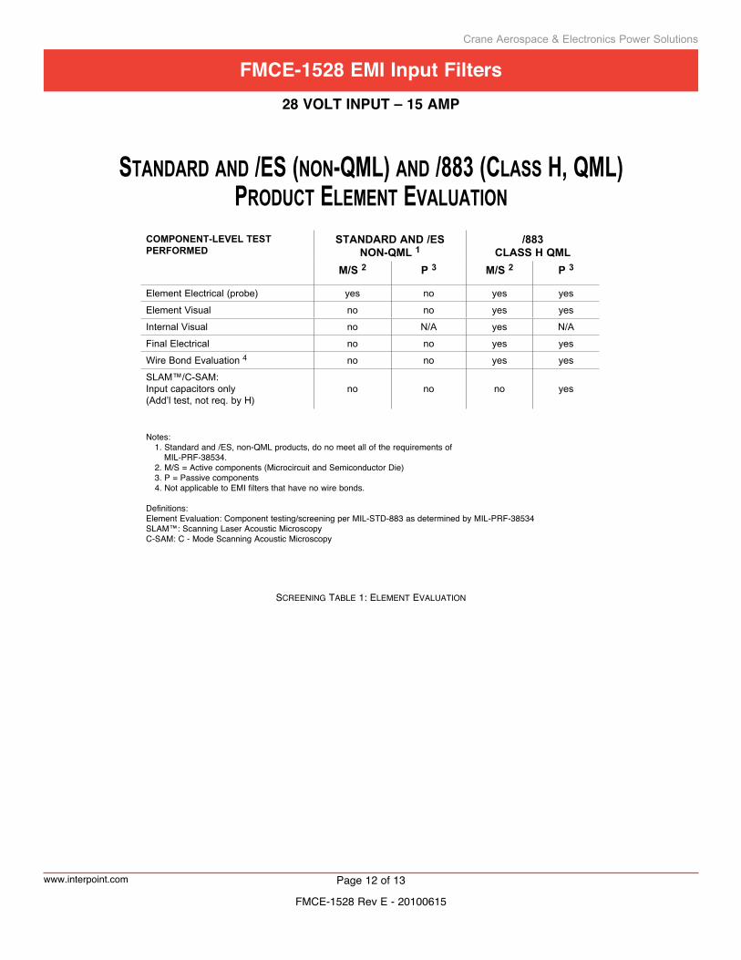
STANDARD AND /ES (NON-QML) AND /883 (CLASS H, QML) PRODUCT ELEMENT EVALUATION
COmpOnent-level test perFOrmed
standard and /esnOn-Qml 1
/883Class h Qml
M/S 2 P 3 M/S 2 P 3
Element Electrical (probe) yes no yes yes
Element Visual no no yes yes
Internal Visual no N/A yes N/A
Final Electrical no no yes yes
Wire Bond Evaluation 4 no no yes yes
SLAM™/C-SAM: Input capacitors only (Add’l test, not req. by H)
no no no yes
Notes: 1. Standard and /ES, non-QML products, do no meet all of the requirements of MIL-PRF-38534. 2. M/S = Active components (Microcircuit and Semiconductor Die) 3. P = Passive components 4. Not applicable to EMI filters that have no wire bonds.
Definitions:Element Evaluation: Component testing/screening per MIL-STD-883 as determined by MIL-PRF-38534SLAM™: Scanning Laser Acoustic MicroscopyC-SAM: C - Mode Scanning Acoustic Microscopy
scReenIng table 1: eleMent evaluatIOn
Crane Aerospace & Electronics Power Solutions
www.interpoint.com Page 12 of 13
FMce-1528 eMi input Filters28 Volt input – 15 aMp
FMCE-1528 Rev E - 20100615
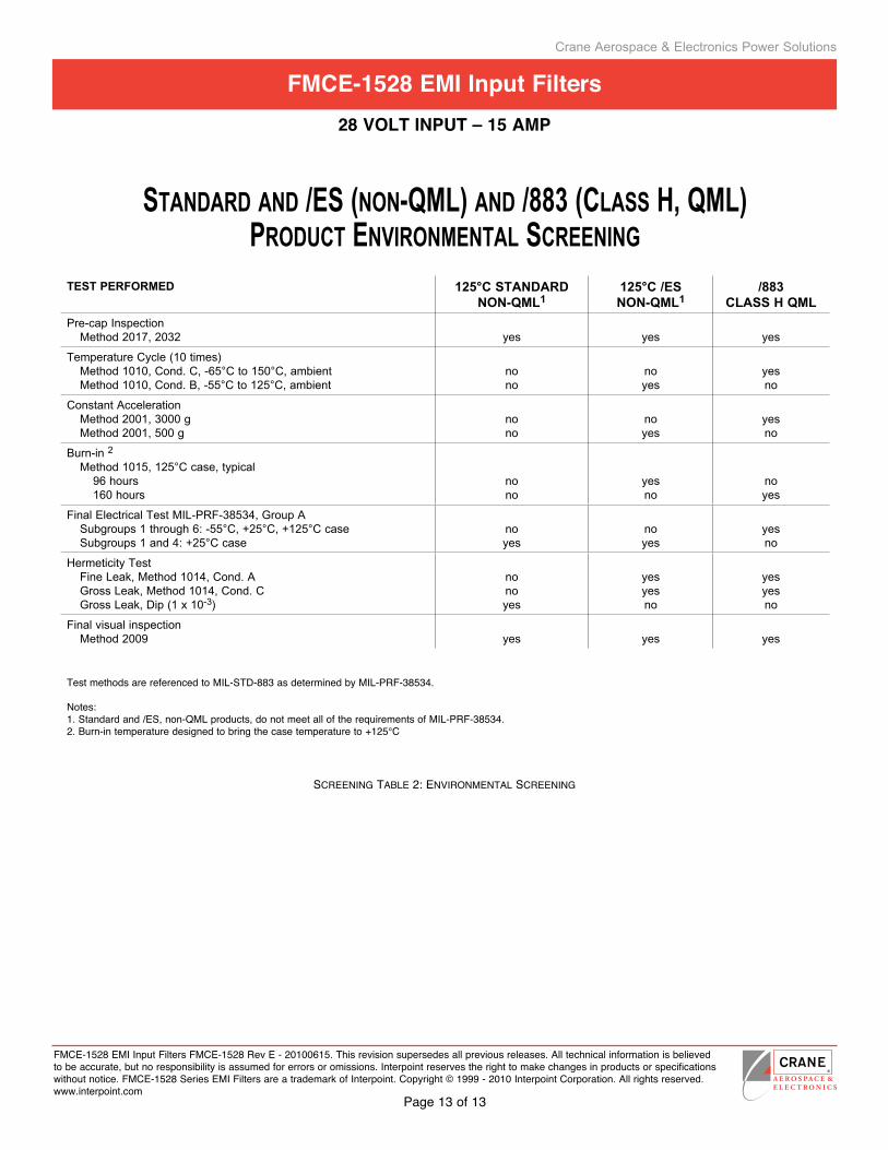
STANDARD AND /ES (NON-QML) AND /883 (CLASS H, QML)PRODUCT ENVIRONMENTAL SCREENING
test perFOrmed 125°C standardnOn-Qml1
125°C /esnOn-Qml1
/883Class h Qml
Pre-cap Inspection Method 2017, 2032 yes yes yes
Temperature Cycle (10 times)Method 1010, Cond. C, -65°C to 150°C, ambientMethod 1010, Cond. B, -55°C to 125°C, ambient
nono
noyes
yesno
Constant Acceleration Method 2001, 3000 g Method 2001, 500 g
nono
noyes
yesno
Burn-in 2
Method 1015, 125°C case, typical96 hours160 hours
nono
yesno
noyes
Final Electrical Test MIL-PRF-38534, Group A Subgroups 1 through 6: -55°C, +25°C, +125°C caseSubgroups 1 and 4: +25°C case
noyes
noyes
yesno
Hermeticity TestFine Leak, Method 1014, Cond. AGross Leak, Method 1014, Cond. CGross Leak, Dip (1 x 10⁻³)
nonoyes
yesyesno
yesyesno
Final visual inspectionMethod 2009 yes yes yes
Test methods are referenced to MIL-STD-883 as determined by MIL-PRF-38534.
Notes:1. Standard and /ES, non-QML products, do not meet all of the requirements of MIL-PRF-38534.2. Burn-in temperature designed to bring the case temperature to +125°C
scReenIng table 2: envIROnMental scReenIng
Crane Aerospace & Electronics Power Solutions
FMCE-1528 EMI Input Filters FMCE-1528 Rev E - 20100615. This revision supersedes all previous releases. All technical information is believed to be accurate, but no responsibility is assumed for errors or omissions. Interpoint reserves the right to make changes in products or specifications without notice. FMCE-1528 Series EMI Filters are a trademark of Interpoint. Copyright © 1999 - 2010 Interpoint Corporation. All rights reserved. www.interpoint.com
Page 13 of 13
FMce-1528 eMi input Filters28 Volt input – 15 aMp