
2755-6.3, Hand-Held Cordless Bar Code Scanners User Manual€¦ · Hand-Held Cordless Bar Code...
107
User Manual Hand-Held Cordless Bar Code Scanners (Cat. Nos. 2755-HCG-4 and 2755-HCG-7) Allen-Bradley
Transcript of 2755-6.3, Hand-Held Cordless Bar Code Scanners User Manual€¦ · Hand-Held Cordless Bar Code...

UserManual
Hand-HeldCordless BarCode Scanners
(Cat. Nos.2755-HCG-4 and2755-HCG-7)
Allen-Bradley

Important User Information
The illustrations, charts, sample programs and layout examplesshown in this guide are intended solely for purposes of example.Since there are many variables and requirements associated with anyparticular installation, Allen-Bradley does not assume responsibilityor liability (to include intellectual property liability) for actual usebased upon the examples shown in this publication.
Allen-Bradley publication SGI-1.1, Safety Guidelines for theApplication, Installation, and Maintenance of Solid-State Control(available from your local Allen-Bradley office), describes someimportant differences between solid-state equipment andelectromechanical devices that should be taken into considerationwhen applying products such as those described in this publication.
Reproduction of the contents of this copyrighted publication, inwhole or in part, without written permission of Allen-BradleyCompany, Inc., is prohibited.
Throughout this manual we use notes to make you aware of safetyconsiderations:
!ATTENTION: Identifies information about practicesor circumstances that can lead to personal injury ordeath, property damage or economic loss.
Attention statements help you to:
• identify a hazard
• avoid the hazard
• recognize the consequences
Important: Identifies information that is critical for successfulapplication and understanding of the product.
SLC, Dataliner, T-View, and MessageView are trademarks of Allen-Bradley Company, Inc.PLC is a registered trademark of Allen-Bradley Company, Inc.IBM is a registered trademark of International Business Machines, Inc.DEC is a registered trademark of Digital Equipment Corporation
Publication 2755-6.3
Publication 2755-6.3
Preface
Intended Audience P–1. . . . . . . . . . . . . . . . . . . . . . . . . . . . . . . . . . Contents of this Manual P–2. . . . . . . . . . . . . . . . . . . . . . . . . . . . . . . Related Publications P–3. . . . . . . . . . . . . . . . . . . . . . . . . . . . . . . . . FCC Requirements P–3. . . . . . . . . . . . . . . . . . . . . . . . . . . . . . . . . .
Scanner Requirements P–3. . . . . . . . . . . . . . . . . . . . . . . . . . . . . 4-Slot Battery Charger Requirements P–4. . . . . . . . . . . . . . . . . . .
Laser Warning Symbol P–4. . . . . . . . . . . . . . . . . . . . . . . . . . . . . . . .
Chapter 1 Scanner Features
Major Scanner Features 1–2. . . . . . . . . . . . . . . . . . . . . . . . . . . . . . LED Indicators 1–3. . . . . . . . . . . . . . . . . . . . . . . . . . . . . . . . . . . . . Decoding 1–4. . . . . . . . . . . . . . . . . . . . . . . . . . . . . . . . . . . . . . . . . Safety Information 1–4. . . . . . . . . . . . . . . . . . . . . . . . . . . . . . . . . . . Scanning Ranges 1–6. . . . . . . . . . . . . . . . . . . . . . . . . . . . . . . . . . .
Catalog No. 2755-HCG-4 1–6. . . . . . . . . . . . . . . . . . . . . . . . . . . . Catalog No. 2755-HCG-7 1–6. . . . . . . . . . . . . . . . . . . . . . . . . . . .
Accessories 1–9. . . . . . . . . . . . . . . . . . . . . . . . . . . . . . . . . . . . . . .
Chapter 2 Installing Your Hardware
Important Notes on Scanner Systems 2–2. . . . . . . . . . . . . . . . . . . . . 1. Unpacking the Equipment 2–2. . . . . . . . . . . . . . . . . . . . . . . . . . . 2. Setting the Address of the Base/Charger Unit 2–3. . . . . . . . . . . . . 3. Connecting the Host Cable to the Base/Charger Unit 2–5. . . . . . . . 4. Mounting the Base/Charger Unit 2–7. . . . . . . . . . . . . . . . . . . . . . 5. Mounting the Power Supply 2–9. . . . . . . . . . . . . . . . . . . . . . . . . . 6. Connecting the Power Supply to the Base/Charger Unit andPower Receptacle 2–10. . . . . . . . . . . . . . . . . . . . . . . . . . . . . . . . . . .
����� �� ��������

Table of Contentstoc–ii
Publication 2755-6.3
7. Connecting the Host Cable to the Host Device 2–11. . . . . . . . . . . . 8. Charging the Battery 2–13. . . . . . . . . . . . . . . . . . . . . . . . . . . . . . . 9. Pairing the Scanner to the Base/Charger Unit 2–16. . . . . . . . . . . . .
Chapter 3 Configuring Your Scanner
Important Notes on Configuring a Scanner 3–1. . . . . . . . . . . . . . . . . Available Symbologies 3–2. . . . . . . . . . . . . . . . . . . . . . . . . . . . . . . . Scanner Bar Codes 3–2. . . . . . . . . . . . . . . . . . . . . . . . . . . . . . . . . . Scanner Default Settings 3–3. . . . . . . . . . . . . . . . . . . . . . . . . . . . . . Parameter Selections 3–6. . . . . . . . . . . . . . . . . . . . . . . . . . . . . . . . Parameter Descriptions 3–8. . . . . . . . . . . . . . . . . . . . . . . . . . . . . . .
Host Interface Code 3–8. . . . . . . . . . . . . . . . . . . . . . . . . . . . . . . . Code types 3–8. . . . . . . . . . . . . . . . . . . . . . . . . . . . . . . . . . . . . . Code 39 Full ASCII 3–8. . . . . . . . . . . . . . . . . . . . . . . . . . . . . . . . Code 39 Any Length 3–9. . . . . . . . . . . . . . . . . . . . . . . . . . . . . . . Code 39 Length Within Range 3–9. . . . . . . . . . . . . . . . . . . . . . . . Code 39 One Length 3–9. . . . . . . . . . . . . . . . . . . . . . . . . . . . . . . Code 39 Two Lengths 3–9. . . . . . . . . . . . . . . . . . . . . . . . . . . . . . Code 128 Any Length 3–9. . . . . . . . . . . . . . . . . . . . . . . . . . . . . . Codabar Any Length 3–9. . . . . . . . . . . . . . . . . . . . . . . . . . . . . . . Codabar Length Within Range 3–9. . . . . . . . . . . . . . . . . . . . . . . . Codabar One Length 3–9. . . . . . . . . . . . . . . . . . . . . . . . . . . . . . . Codabar Two Lengths 3–10. . . . . . . . . . . . . . . . . . . . . . . . . . . . . . I 2 of 5 Any Length 3–10. . . . . . . . . . . . . . . . . . . . . . . . . . . . . . . . I 2 of 5 Length Within Range 3–10. . . . . . . . . . . . . . . . . . . . . . . . . I 2 of 5 One Length 3–10. . . . . . . . . . . . . . . . . . . . . . . . . . . . . . . . I 2 of 5 Two Lengths 3–10. . . . . . . . . . . . . . . . . . . . . . . . . . . . . . . D 2 of 5 Any Length 3–10. . . . . . . . . . . . . . . . . . . . . . . . . . . . . . . . D 2 of 5 Length Within Range 3–10. . . . . . . . . . . . . . . . . . . . . . . . . D 2 of 5 One Length 3–10. . . . . . . . . . . . . . . . . . . . . . . . . . . . . . . D 2 of 5 Two Lengths 3–11. . . . . . . . . . . . . . . . . . . . . . . . . . . . . . . MSI Plessey Any Length 3–11. . . . . . . . . . . . . . . . . . . . . . . . . . . . MSI Plessey Length Within Range 3–11. . . . . . . . . . . . . . . . . . . . .

Table of Contents toc–iii
Publication 2755-6.3
Publication 2755-6.3
MSI Plessey One Length 3–11. . . . . . . . . . . . . . . . . . . . . . . . . . . . MSI Plessey Two Lengths 3–11. . . . . . . . . . . . . . . . . . . . . . . . . . . Transmit UPC-A Check Digit 3–11. . . . . . . . . . . . . . . . . . . . . . . . . Transmit UPC-E Check Digit 3–11. . . . . . . . . . . . . . . . . . . . . . . . . Convert UPC-E to UPC-A 3–12. . . . . . . . . . . . . . . . . . . . . . . . . . . EAN Zero Extend 3–12. . . . . . . . . . . . . . . . . . . . . . . . . . . . . . . . . Transmit No Decode Message 3–12. . . . . . . . . . . . . . . . . . . . . . . . UPC / EAN Supplemental 3–12. . . . . . . . . . . . . . . . . . . . . . . . . . . I 2 of 5 (14 digit) to EAN 13 Conversion 3–12. . . . . . . . . . . . . . . . . . Code 39 Check Digit 3–12. . . . . . . . . . . . . . . . . . . . . . . . . . . . . . . MSI Plessey check Digit 3–13. . . . . . . . . . . . . . . . . . . . . . . . . . . . Code 39 Buffering (Scan and Store) 3–13. . . . . . . . . . . . . . . . . . . . Beeper Volume 3–13. . . . . . . . . . . . . . . . . . . . . . . . . . . . . . . . . . . Beep After Good Decode 3–14. . . . . . . . . . . . . . . . . . . . . . . . . . . . UPC / EAN Security Level 3–14. . . . . . . . . . . . . . . . . . . . . . . . . . . Decode Redundancy 3–14. . . . . . . . . . . . . . . . . . . . . . . . . . . . . . . UPC-A / UPC-E Preambles 3–15. . . . . . . . . . . . . . . . . . . . . . . . . . Pause Duration 3–15. . . . . . . . . . . . . . . . . . . . . . . . . . . . . . . . . . . Scan Prefix 3–15. . . . . . . . . . . . . . . . . . . . . . . . . . . . . . . . . . . . . . Scan Suffix 3–15. . . . . . . . . . . . . . . . . . . . . . . . . . . . . . . . . . . . . . Data Transmission Formats 3–16. . . . . . . . . . . . . . . . . . . . . . . . . . Laser On Time-Out 3–16. . . . . . . . . . . . . . . . . . . . . . . . . . . . . . . . Baud Rate 3–16. . . . . . . . . . . . . . . . . . . . . . . . . . . . . . . . . . . . . . Parity 3–17. . . . . . . . . . . . . . . . . . . . . . . . . . . . . . . . . . . . . . . . . . Check Parity 3–17. . . . . . . . . . . . . . . . . . . . . . . . . . . . . . . . . . . . . Hardware Handshaking 3–17. . . . . . . . . . . . . . . . . . . . . . . . . . . . . Software Handshaking 3–18. . . . . . . . . . . . . . . . . . . . . . . . . . . . . . Serial Response Time-out 3–19. . . . . . . . . . . . . . . . . . . . . . . . . . . Stop Bit Select 3–19. . . . . . . . . . . . . . . . . . . . . . . . . . . . . . . . . . . ASCII Format 3–19. . . . . . . . . . . . . . . . . . . . . . . . . . . . . . . . . . . . RTS Line State 3–19. . . . . . . . . . . . . . . . . . . . . . . . . . . . . . . . . . . Intercharacter Delay 3–20. . . . . . . . . . . . . . . . . . . . . . . . . . . . . . . Transmit Code ID Characters 3–20. . . . . . . . . . . . . . . . . . . . . . . . .
Table of Contentstoc–iv
Publication 2755-6.3
Transmit AIM Code ID 3–20. . . . . . . . . . . . . . . . . . . . . . . . . . . . . . Ignore Unknown Characters 3–20. . . . . . . . . . . . . . . . . . . . . . . . . . International Keyboard Emulation 3–21. . . . . . . . . . . . . . . . . . . . . . International Keyboard Emulation Fast Transmit 3–21. . . . . . . . . . . National Keyboard Type 3–21. . . . . . . . . . . . . . . . . . . . . . . . . . . . . Set Transmission Frequency 3–21. . . . . . . . . . . . . . . . . . . . . . . . . Wait for Host Interface Response Time 3–21. . . . . . . . . . . . . . . . . .
Configuration Sequence 3–22. . . . . . . . . . . . . . . . . . . . . . . . . . . . . .
Chapter 4 Scanner Operation
Important Notes on Using Your Scanner 4–1. . . . . . . . . . . . . . . . . . . Testing Your Scanner 4–1. . . . . . . . . . . . . . . . . . . . . . . . . . . . . . . . . Scanning Bar Codes 4–2. . . . . . . . . . . . . . . . . . . . . . . . . . . . . . . . .
Chapter 5 Maintenance and Troubleshooting
Charging the Battery 5–2. . . . . . . . . . . . . . . . . . . . . . . . . . . . . . . . . In the Gun 5–2. . . . . . . . . . . . . . . . . . . . . . . . . . . . . . . . . . . . . . In the 4-Slot Battery Charger 5–5. . . . . . . . . . . . . . . . . . . . . . . . .
Conditioning the Battery 5–9. . . . . . . . . . . . . . . . . . . . . . . . . . . . . . . Changing the Battery Pack in the Scanner Gun 5–10. . . . . . . . . . . . . . Cleaning the Scan Window 5–12. . . . . . . . . . . . . . . . . . . . . . . . . . . . Troubleshooting the Scanners 5–13. . . . . . . . . . . . . . . . . . . . . . . . . . Troubleshooting the 4-Slot Battery Charger 5–15. . . . . . . . . . . . . . . . .
4-Slot Battery Charger LED Status 5–15. . . . . . . . . . . . . . . . . . . . . Identifying 4-Slot Battery Charger Errors 5–16. . . . . . . . . . . . . . . . .
Listening for an Audible Response 5–18. . . . . . . . . . . . . . . . . . . . . . . Beep During Normal Operation 5–18. . . . . . . . . . . . . . . . . . . . . . . . Beep During Entering Parameter Bar Codes 5–18. . . . . . . . . . . . . . Beep During Code 39 Scan and Store 5–19. . . . . . . . . . . . . . . . . . .
Contacting Allen-Bradley Global Technical Services 5–19. . . . . . . . . . .

Table of Contents toc–v
Publication 2755-6.3
Publication 2755-6.3
Appendix A Specifications
Scanner Specifications A–1. . . . . . . . . . . . . . . . . . . . . . . . . . . . . . . 4-Slot Battery Charger Specifications A–3. . . . . . . . . . . . . . . . . . . . . Power Supply Specifications A–3. . . . . . . . . . . . . . . . . . . . . . . . . . . Base/Charger Unit Specifications A–4. . . . . . . . . . . . . . . . . . . . . . . .
Appendix B Cable Pinouts
RS-232-C, 25-pin DB, male, Txd on Pin 3 (Catalog No. 2755-HCC-BR2-06) B–2. . . . . . . . . . . . . . . . . . . . .
RS-232-C, 25-pin DB, male, Txd on Pin 2 (Catalog No. 2755-HCC-BR1-06) B–3. . . . . . . . . . . . . . . . . . . . .
IBM XT/AT keyboard, 5-pin DIN(Catalog No. 2755-HCC-BP1-06) B–4. . . . . . . . . . . . . . . . . . . . .
PS/2 keyboard. 6-pin Mini-DIN(Catalog No. 2755-HCC-BP2-06) B–5. . . . . . . . . . . . . . . . . . . . .
DEC VT2xx, 3xx, 4xx keyboards(Catalog No. 2755-HCC-BV1-06) B–6. . . . . . . . . . . . . . . . . . . . .
Appendix C Advanced Data Formatting
ADF Overview C–1. . . . . . . . . . . . . . . . . . . . . . . . . . . . . . . . . . . . . Criteria C–2. . . . . . . . . . . . . . . . . . . . . . . . . . . . . . . . . . . . . . . . . Actions C–3. . . . . . . . . . . . . . . . . . . . . . . . . . . . . . . . . . . . . . . . .
Rules Hierarchy C–3. . . . . . . . . . . . . . . . . . . . . . . . . . . . . . . . . . . . Default Rule C–3. . . . . . . . . . . . . . . . . . . . . . . . . . . . . . . . . . . . . . . Listening for an ADF Audible Response C–4. . . . . . . . . . . . . . . . . . .
Beep Indicating Normal Operation C–4. . . . . . . . . . . . . . . . . . . . . Beep Indicating Error C–5. . . . . . . . . . . . . . . . . . . . . . . . . . . . . . .
ADF Sorting Application Example C–6. . . . . . . . . . . . . . . . . . . . . . . .
Glossary
Preface
Publication 2755-6.3
Publication 2755-6.3
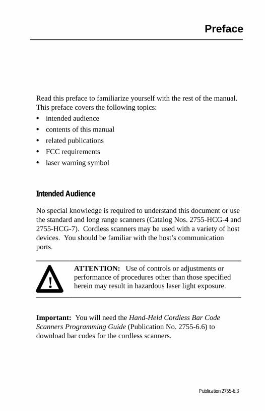
Read this preface to familiarize yourself with the rest of the manual.This preface covers the following topics:
• intended audience
• contents of this manual
• related publications
• FCC requirements
• laser warning symbol
Intended Audience
No special knowledge is required to understand this document or usethe standard and long range scanners (Catalog Nos. 2755-HCG-4 and2755-HCG-7). Cordless scanners may be used with a variety of hostdevices. You should be familiar with the host’s communicationports.
!ATTENTION: Use of controls or adjustments orperformance of procedures other than those specifiedherein may result in hazardous laser light exposure.
Important: You will need the Hand-Held Cordless Bar CodeScanners Programming Guide (Publication No. 2755-6.6) todownload bar codes for the cordless scanners.
PrefaceP–2
Publication 2755-6.3
Publication 2755-6.3
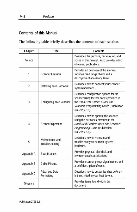
Contents of this Manual
The following table briefly describes the contents of each section.
Chapter Title Contents
PrefaceDescribes the purpose, background, andscope of this manual. Also provides a listof related publications.
1 Scanner FeaturesProvides an overview of the scanner.Includes read range charts and adescription of accessory items.
2 Installing Your HardwareDescribes how to connect your scannersystem hardware.
3 Configuring Your Scanner
Describes configuration options for thescanner using the bar codes provided inthe Hand-Held Cordless Bar CodeScanners Programming Guide (PublicationNo. 2755-6.6).
4 Scanner Operation
Describes how to operate the scannerusing the bar codes provided in theHand-Held Cordless Bar Code ScannersProgramming Guide (Publication No. 2755-6.6).
5Maintenance andTroubleshooting
Describes how to maintain andtroubleshoot your scanner systemhardware.
Appendix A SpecificationsProvides physical, electrical, andenvironmental specifications.
Appendix B Cable PinoutsProvides scanner pinout signal names anda brief description of each.
Appendix CAdvanced DataFormatting
Describes how to customize data before itis transmitted to your host device.
GlossaryProvides terms found within thisdocument.

Preface P–3
Publication 2755-6.3
Publication 2755-6.3
Related Publications
Below is a list of related publications you may need to refer to whenusing the cordless scanners.
Publication No. Title
2755-6.6 Hand-Held Cordless Bar Code Scanners Programming Guide
2755-921 Bar Code Basics
FCC Requirements
Refer to the following sections for the FCC requirements for thestandard and long range scanners (Catalog Nos. 2755-HCG-4 and2755-HCG-7) and 4–slot battery charger (Catalog No. 2755-HCP-B2).
Scanner Requirements
The scanners comply with Part 15 of the FCC Rules and CanadianRSS:210. Operation is subject to the following two conditions:
• This device may not cause harmful interference, and
• must accept any interference received, including interference thatmay cause undesired operation.
This equipment has been tested and found to comply with the limitsfor a Class B digital device, pursuant to Part 15 of the FCC Rules.These limits are designed to provide reasonable protection againstharmful interference when the equipment is operated in acommercial environment. This equipment generates, uses, and canradiate radio frequency energy and, if not installed and used inaccordance with this user manual, may cause harmful interference toradio communications. Operation of this equipment in a residentialarea is likely to cause harmful interference in which case the userwill be required to correct the interference at his own expense.
PrefaceP–4
Publication 2755-6.3
Publication 2755-6.3
4-Slot Battery Charger Requirements
This device complies with Part 15 of the FCC Rules. See FCC labelfor additional information.
This equipment has been tested and found to comply with the limitsfor a Class A digital service, pursuant to Part 15 of the FCC Rules.These limits are designed to provide reasonable protection againstharmful interference when the equipment is operated in acommercial environment. This equipment generates, uses, and canradiate radio frequency energy and, if not installed and used inaccordance with this user manual, may cause harmful interference toradio communications. Operation of this equipment in a residentialarea is likely to cause harmful interference in which case the userwill be required to correct the interference at his own expense.
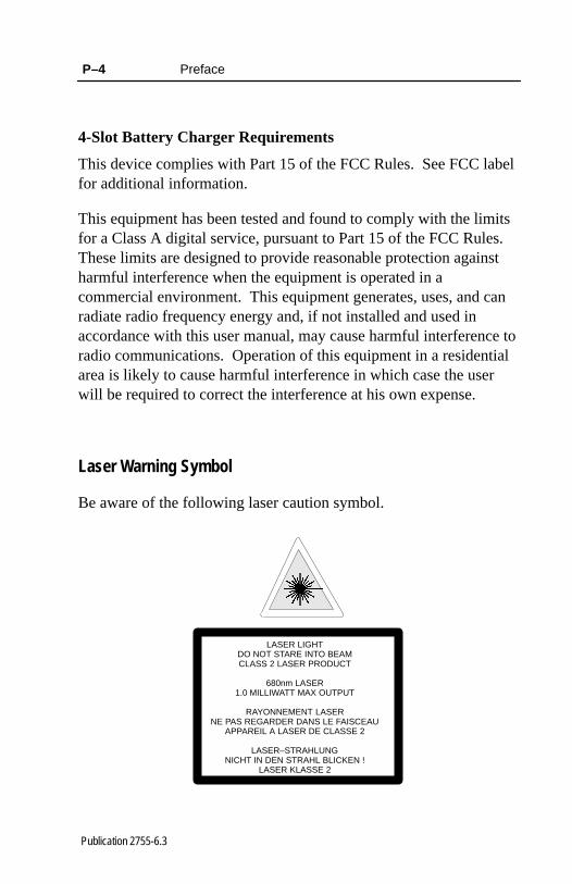
Laser Warning Symbol
Be aware of the following laser caution symbol.
LASER LIGHTDO NOT STARE INTO BEAMCLASS 2 LASER PRODUCT
680nm LASER1.0 MILLIWATT MAX OUTPUT
RAYONNEMENT LASERNE PAS REGARDER DANS LE FAISCEAU
APPAREIL A LASER DE CLASSE 2
LASER–STRAHLUNGNICHT IN DEN STRAHL BLICKEN !
LASER KLASSE 2

������� �
Publication 2755-6.3
������� ������
This chapter describes the features of the standard and long rangecordless scanners (Catalog Nos. 2755-HCG-4 and 2755-HCG-7).Included are descriptions of:
• major scanner features
• LED indicators
• decoding
• safety information
• scanning ranges
• accessories

1–2 Scanner Features
Publication 2755-6.3
Major Scanner Features
The scanners use a low power visible (red) laser diode for scanning.The trigger turns on the laser which scans a label at approximately36 scans per second.
Trigger
LEDs
Battery PackHandle Release Button
Scan Window
Laser LightReflected Light
The laser beam:
• exits through the scan window
• reflects off the label back through the window
• is detected by a sensor in the scanner
When a label is read, the laser beam is automatically turned off untilthe trigger is pressed again. If no label is read, the laser beamautomatically turns off after 0.5 to 3 seconds (timeout is adjustable)and remains off until the trigger is released and pressed again.
Scanner Features 1–3
Publication 2755-6.3
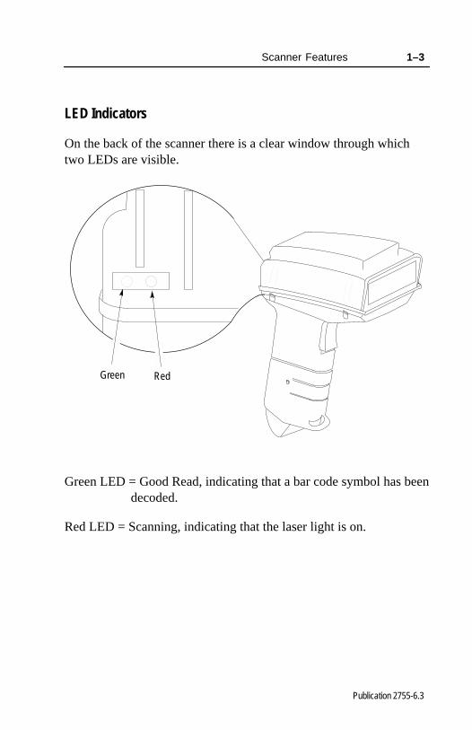
LED Indicators
On the back of the scanner there is a clear window through whichtwo LEDs are visible.
Green Red
Green LED = Good Read, indicating that a bar code symbol has been decoded.
Red LED = Scanning, indicating that the laser light is on.

1–4 Scanner Features
Publication 2755-6.3
Decoding
The scanners can decode the following symbologies:
• UPC-A
• UPC-E
• Code 39 Full ASCII
• Code 39
• Code 128
• EAN 8
• EAN 13
• EAN 128
• Codabar
• Interleaved 2 of 5
• Discrete 2 of 5
• MSI Plessey
The scanners are autodiscriminating so that multiple symbologiesmay be enabled at the same time. The only exception is the scannerscannot discriminate between Code 39 and Code 39 Full ASCII.
Safety Information
The scanners use a low power visible laser diode. As with any brightlight source, you should avoid staring directly into the beam.Momentary exposure to a CDRH Class II laser is not known to beharmful.
!ATTENTION: Use of controls or adjustments orperformance of procedures other than those specifiedherein may result in hazardous laser light exposure.
Scanner Features 1–5
Publication 2755-6.3
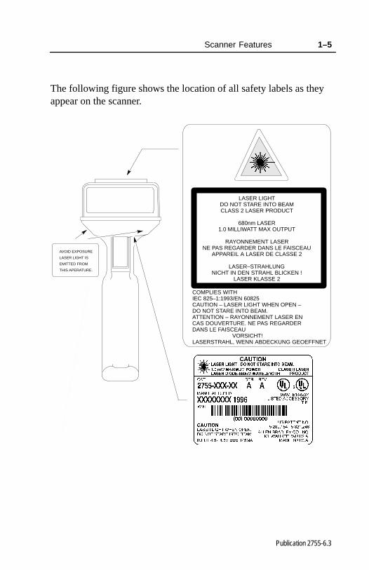
The following figure shows the location of all safety labels as theyappear on the scanner.
AVOID EXPOSURE
LASER LIGHT IS
EMITTED FROM
THIS APERATURE.
LASER LIGHTDO NOT STARE INTO BEAMCLASS 2 LASER PRODUCT
680nm LASER1.0 MILLIWATT MAX OUTPUT
RAYONNEMENT LASERNE PAS REGARDER DANS LE FAISCEAU
APPAREIL A LASER DE CLASSE 2
LASER–STRAHLUNGNICHT IN DEN STRAHL BLICKEN !
LASER KLASSE 2
COMPLIES WITHIEC 825–1:1993/EN 60825CAUTION – LASER LIGHT WHEN OPEN –DO NOT STARE INTO BEAM.ATTENTION – RAYONNEMENT LASER ENCAS DOUVERTURE. NE PAS REGARDERDANS LE FAISCEAU VORSICHT!LASERSTRAHL, WENN ABDECKUNG GEOEFFNET

1–6 Scanner Features
Publication 2755-6.3
Scanning Ranges
The scanners can read bar code symbols at various distancesdepending upon the type of scanner and narrowest bar code width(width of smallest bars or spaces).
Catalog No. 2755-HCG-4
Minimum Bar CodeWidth
Read Range
5.0 mil(0.13 mm)
1.0 in. to 3.0 in.(2.5 cm to 7.6 cm)
7.5 mil(0.19 mm)
0.0 in. to 7.0 in.(0.0 cm to 17.8 cm)
20.0 mil(0.51 mm)
0.0 in. to 19.0 in.(0.0 cm to 48.3 cm)
40.0 mil(1.02 mm)
2.0 in. to 27.5 in. (5.1 cm to 69.9 cm)
55.0 mil(1.40 mm)
2.75 in. to 35.0 in.(7.0 cm to 88.9 cm)
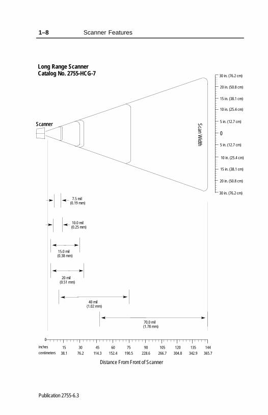
Catalog No. 2755-HCG-7
Minimum Bar CodeWidth
Read Range
7.5 mil(0.19 mm)
7.0 in. to 12.0 in.(17.8 cm to 30.5 cm)
10.0 mil(0.25 mm)
5.0 in. to 15.0 in.(12.7 cm to 38.1 cm)
15.0 mil(0.38 mm)
3.0 in. to 30.0 in.(7.62 cm to 76.2 cm)
20.0 mil(0.51 mm)
3.0 in. to 34.0 in.(7.62 cm to 86.4 cm)
40.0 mil(1.02 mm)
10.0 in. to 75.0 in. (25.4 cm to 190.5 cm)
70.0 mil(1.78 mm)
48.0 in. to 144.0 in.(121.9 cm to 365.7 cm)

Scanner Features 1–7
Publication 2755-6.3
0
30 35
0
5 in. (12.7 cm)
10 in. (25.4 cm)
40 mil
5 mil
Distance From Front of Scanner
76 89
inches
centimeters252015105
7.5 mil(0.19 mm)
(1.02 mm)
(0.13 mm)
12.7 25 38 51 64
Standard Range ScannerCatalog No. 2755-HCG-4
Scanner
5 in. (12.7 cm)
10 in. (25.4 cm)
55 mil(1.40 mm)
Scan Width
20 mil(0.51 mm)
Scanner
1–8 Scanner Features
Publication 2755-6.3
0
90 105
0
5 in. (12.7 cm)
10 in. (25.4 cm)
40 mil
Distance From Front of Scanner
228.6 266.7
inches
centimeters7560453015
7.5 mil(0.19 mm)
(1.02 mm)
38.1 76.2 114.3 152.4 190.5
Long Range ScannerCatalog No. 2755-HCG-7
Scanner
5 in. (12.7 cm)
10 in. (25.4 cm)
120304.8
70.0 mil(1.78 mm)
Scan Width
20 mil(0.51 mm)
Scanner
135342.9
144365.7
15 in. (38.1 cm)
20 in. (50.8 cm)
15 in. (38.1 cm)
20 in. (50.8 cm)
30 in. (76.2 cm)
30 in. (76.2 cm)
15.0 mil(0.38 mm)
10.0 mil(0.25 mm)

Scanner Features 1–9
Publication 2755-6.3
Accessories
The following accessories are available.
• Power Supply – Connects to and provides power for thebase/charger unit.
– 100–240V ac, 50–60 Hz (Catalog No. 2755-HCP-D1)• RS-232 Cables – Connects the base/charger unit to host RS-232
port. See appendix B for connections.
– RS-232-C, 25-pin DB, male, Txd on Pin 3 (Catalog No. 2755-HCC-BR2-06)
– RS-232-C, 25-pin DB, male, Txd on Pin 2 (Catalog No. 2755-HCC-BR1-06)
• Keyboard Wedge Cables – Connects the base/charger unit tokeyboard and terminal. See appendix B for connections.
– For IBM� XT/AT keyboard, 5-pin DIN(Catalog No. 2755-HCC-BP1-06)
– For PS/2 keyboard. 6-pin Mini-DIN(Catalog No. 2755-HCC-BP2-06)
– For DEC� VT2xx, 3xx, 4xx keyboards(Catalog No. 2755-HCC-BV1-06)
• Stands – Provides storage for the scanner gun.
– 5 to 8 inch (127 to 457 mm) height(Catalog No. 2755-HFN-K1)
– 9 to 16 inch (229 to 406 mm) height(Catalog No. 2755-HFN-K2)
– Multi-mount Stand (Catalog No. 2755-HFN-K3)• Protective Boot – Heavy canvas boot provides additional
protection for the scanner gun (Catalog No. 2755-HCN-H1).
• Base/Charger Unit – (Catalog No. 2755-HCG-B)
• Holster – (Catalog No. 2755-HCN-H2)
• Belt Clip – (Catalog No. 2755-HCN-H3)
• Battery Pack – (Catalog No. 2755-HCP-B1)

1–10 Scanner Features
Publication 2755-6.3
• 4-Slot Desk Mount Universal Rapid Battery Charger – (Catalog No. 2755-HCP-B2)
• Battery Mounting Adapter for Universal Battery Charger –(Catalog No. 2755-HCP-B3)

�������
Publication 2755-6.3
������ �� ��� ��������
This chapter describes how to install your hardware. Included is thefollowing sequence on installing your scanner system hardware.
1. unpacking the equipment
2. setting the address of the base/charger unit
3. connecting the host cable to the base/charger unit
4. mounting the base/charger unit
5. mounting the power supply
6. connecting the power supply to the base/charger unit and powerreceptacle
7. connecting the host cable to the host device
8. charging the battery
9. pairing the scanner to the base/charger unit

2–2 Installing Your Hardware
Publication 2755-6.3
Important Notes on Scanner Systems
The following illustrates the base/charger unit connected to the hostdevice and power supply.
Host
Power Supply
Base/Charger Unit
Be aware of the following when setting up your scanner system.
• The gun operates up to 50 ft (15.24 m) from the host devicedepending on the application environment.
• The gun turns itself off after each successful data transmission toconserve battery life.
• Average life of a battery charge is 8 hours. Replace or rechargethe battery at the end of the work shift.
• There is a 1-to-1 pairing of guns to bases. (You cannot havemultiple guns paired to one base or one gun paired to multiplebases.)
• You need to pair the scanner with the base/charger unit afterreplacing the battery in the scanner gun. Refer to page 2–16 forinformation regarding pairing the scanner to the base/chargerunit.
• The base/charger unit cannot be placed in an enclosure. RFcommunication between the gun and the base/charger unit will beaffected by the enclosure. However, you should protect thebase/charger unit from airborne contaminants.
1. Unpacking the EquipmentRemove the scanner, base/charger unit, power supply, and hostinterface cable from their packing and inspect for physical damage.If there is damage, contact Allen-Bradley Global Technical Services(GTS) at (216) 646-6800.

Installing Your Hardware 2–3
Publication 2755-6.3
2. Setting the Address of the Base/Charger Unit
You need to set the address of the base/charger unit (Catalog No. 2755-HCG-B) in order to pair the scanner with thebase. Pairing allows communication to occur between these twounits. Be aware of the following when pairing the scanner to thebase/charger unit.
• There is a 1-to-1 pairing of guns and bases. (You cannot havemultiple guns paired to one base or one gun paired to multiplebases.)
• You can have 128 gun/base pairs within the same RFcommunication range.
• Communication between the gun and the base/charger unit maybe affected by environmental conditions such as the amount ofmetal located near the gun and base/charger unit.
• You need to pair a gun to a base/charger unit after replacing thebattery in the gun.
• The base/charger must be assigned an unique address between 00and 7F.
To set the address:
1. Locate the panel on the underside of the base/charger unit.
Panel
2. Remove the panel.
2–4 Installing Your Hardware
Publication 2755-6.3
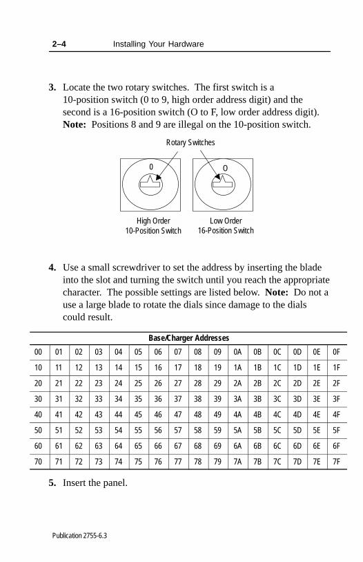
3. Locate the two rotary switches. The first switch is a 10-position switch (0 to 9, high order address digit) and thesecond is a 16-position switch (O to F, low order address digit).Note: Positions 8 and 9 are illegal on the 10-position switch.
Rotary Switches
O0
High Order Low Order10-Position Switch 16-Position Switch
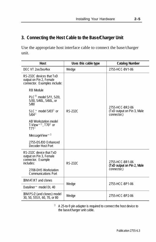
4. Use a small screwdriver to set the address by inserting the bladeinto the slot and turning the switch until you reach the appropriatecharacter. The possible settings are listed below. Note: Do not ause a large blade to rotate the dials since damage to the dialscould result.
Base/Charger Addresses
00 01 02 03 04 05 06 07 08 09 0A 0B 0C 0D 0E 0F
10 11 12 13 14 15 16 17 18 19 1A 1B 1C 1D 1E 1F
20 21 22 23 24 25 26 27 28 29 2A 2B 2C 2D 2E 2F
30 31 32 33 34 35 36 37 38 39 3A 3B 3C 3D 3E 3F
40 41 42 43 44 45 46 47 48 49 4A 4B 4C 4D 4E 4F
50 51 52 53 54 55 56 57 58 59 5A 5B 5C 5D 5E 5F
60 61 62 63 64 65 66 67 68 69 6A 6B 6C 6D 6E 6F
70 71 72 73 74 75 76 77 78 79 7A 7B 7C 7D 7E 7F
5. Insert the panel.
Installing Your Hardware 2–5
Publication 2755-6.3
3. Connecting the Host Cable to the Base/Charger Unit
Use the appropriate host interface cable to connect the base/chargerunit.
Host Uses this cable type Catalog Number
DEC VT 2xx/3xx/4xx Wedge 2755-HCC-BV1-06
RS-232C devices that TxDoutput on Pin 2, Femaleconnector. Examples include:
RB Module
PLC� model 5/11, 5/20,5/30, 5/40L, 5/60L, or5/80
SLC� model 5/03➀ or5/04➀
RS-232C2755-HCC-BR2-06(TxD output on Pin 3, Maleconnector.)
AB Workstation modelT-View�➀ , T70➀ orT71➀
MessageView�➀
2755-DS/DD EnhancedDecoder Host Port
RS-232C device that TxDoutput on Pin 3, Femaleconnector. Exampleincludes: RS-232C 2755-HCC-BR1-06
(TxD output on Pin 2, Male2708-DH5 WorkstationCommunications Port
(TxD output on Pin 2, Maleconnector.)
IBM AT/XT and clones
Dataliner� model DL 40Wedge 2755-HCC-BP1-06
IBM PS/2 (and clones) model30, 50, 55SX, 60, 70, or 80 Wedge 2755-HCC-BP2-06
➀ A 25-to-9 pin adapter is required to connect the host device tothe base/charger unit cable.
2–6 Installing Your Hardware
Publication 2755-6.3
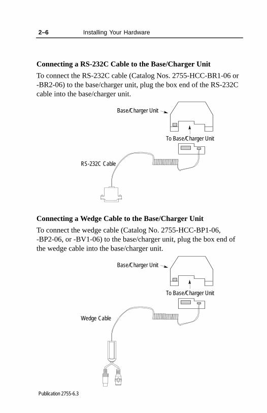
Connecting a RS-232C Cable to the Base/Charger Unit
To connect the RS-232C cable (Catalog Nos. 2755-HCC-BR1-06 or-BR2-06) to the base/charger unit, plug the box end of the RS-232Ccable into the base/charger unit.
RS-232C Cable
Base/Charger Unit
To Base/Charger Unit
Connecting a Wedge Cable to the Base/Charger Unit
To connect the wedge cable (Catalog No. 2755-HCC-BP1-06,-BP2-06, or -BV1-06) to the base/charger unit, plug the box end ofthe wedge cable into the base/charger unit.
Wedge Cable
Base/Charger Unit
To Base/Charger Unit
Installing Your Hardware 2–7
Publication 2755-6.3
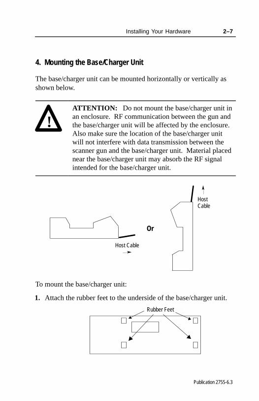
4. Mounting the Base/Charger Unit
The base/charger unit can be mounted horizontally or vertically asshown below.
!ATTENTION: Do not mount the base/charger unit inan enclosure. RF communication between the gun andthe base/charger unit will be affected by the enclosure.Also make sure the location of the base/charger unitwill not interfere with data transmission between thescanner gun and the base/charger unit. Material placednear the base/charger unit may absorb the RF signalintended for the base/charger unit.
Or
Host Cable
Host Cable
To mount the base/charger unit:
1. Attach the rubber feet to the underside of the base/charger unit.
Rubber Feet

2–8 Installing Your Hardware
Publication 2755-6.3
2. Attach the cable bracket to the underside of the base/charger unit.Make sure you have attached the host interface cable first. Youcan remove the bracket by prying it off of the base/charger unitwith a screwdriver.
Cable Bracket
3. Remove the mounting template from the installation instructionsheet. The following figure shows the dimensions of thebase/charger unit.
Mounting Holes
0.875 in.(22.23 mm)
1.5 in.(38.1 mm)
4.75 in.(120.65 mm)
9 in.(228.6 mm)
4 in.(101.6 mm)
1.5 in.(38.1 mm)
1.75 in.(44.45 mm)
4. Secure the template to the mounting surface.
5. Drill holes through the holes marked on the mounting template.
6. Remove the mounting template from the mounting surface.
7. Attach #10 flat-head or pan-head screws to your mountingsurface.

Installing Your Hardware 2–9
Publication 2755-6.3
8. Mount the base/charger unit.
5. Mounting the Power Supply
Place the power supply (Catalog No. 2755-HCP-D1) in an enclosurenear the base/charger unit and power receptacle. Make sure you canplug the power supply into both the base/charger unit and the powerreceptacle. Refer to page 2–10 for more information regardingconnecting the power supply to the base/charger unit and powerreceptacle.
Power Supply
To Base/Charger Unit
To Power Receptacle
Enclosure
The total length of the power supply cable, from the powerreceptacle to the base/charger unit, is 8 ft (2.44 m).
2–10 Installing Your Hardware
Publication 2755-6.3
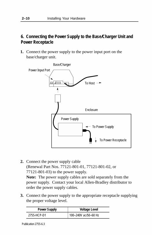
6. Connecting the Power Supply to the Base/Charger Unit andPower Receptacle
1. Connect the power supply to the power input port on thebase/charger unit.
Base/Charger
To Host
Power Supply
Power Input Port
To Power Receptacle
Enclosure
To Power Supply
2. Connect the power supply cable (Renewal Part Nos. 77121-801-01, 77121-801-02, or77121-801-03) to the power supply. Note: The power supply cables are sold separately from thepower supply. Contact your local Allen-Bradley distributor toorder the power supply cables.
3. Connect the power supply to the appropriate receptacle supplyingthe proper voltage level.
Power Supply Voltage Level
2755-HCP-D1 100–240V ac/50–60 Hz

Installing Your Hardware 2–11
Publication 2755-6.3
7. Connecting the Host Cable to the Host Device
The following sections describe how to connect the host cable to thehost device.
Connecting a RS-232C Cable to the Host Device
!ATTENTION: Do not install the RS-232C cable(Catalog Nos. 2755-HCC-BR1-06 or -BR2-06) ordisconnect/connect the host device with power appliedto the host device. Failure to follow this caution mayresult in damage to the base/charger unit, RS-232Ccable, or host device.
To connect the RS-232C cable to the host device:
1. Disconnect power from your host device.
2. Plug the RS-232C cable into the host device.
To Host Device
RS-232C Cable
Base/Charger Unit
3. Reconnect power to your host device.

2–12 Installing Your Hardware
Publication 2755-6.3
Connecting a Wedge Cable to a Host Device
!ATTENTION: Do not install the wedge cable(Catalog No. 2755-HCC-BP1-06, -BP2-06, or-BV1-06) or disconnect/connect the host device withpower applied to either the wedge cable or host device.Failure to follow this caution may result in damage tothe base/charger unit, wedge interface cable, or hostdevice.
To connect the wedge cable to the host device:
1. Disconnect power from your host device.
2. Disconnect the keyboard from the host device.
3. Plug the wedge cable into the host device (i.e., one end into theterminal and the other end into the keyboard).
To Terminal
Wedge Cable
To Keyboard
Base/Charger Unit
4. Reconnect power to your host device.

Installing Your Hardware 2–13
Publication 2755-6.3
8. Charging the Battery
!ATTENTION: Charge a battery (Catalog No. 2755-HCP-B1) at room temperature of65� F (18.3� C) to 70� F (21.1� C) for optimumperformance. Allow the battery to adjust to roomtemperature before charging.
You can charge the battery while the battery is in the gun. Toaccomplish this task:
1. Make sure the battery is in the scanner handle. Make sure thehandle release button is pressed in below the outer housing whensliding a battery into place.
Battery PackHandle Release Button

2–14 Installing Your Hardware
Publication 2755-6.3
2. Place the scanner into the base/charger unit as shown below.Make sure that the unit fits snugly into the base/charger.
3. Check the charge status indicator for a full charge (blinkingrapidly = full charge), which occurs within two hours. However,you can use the scanner with less than a full charge.
Charge Status LED

Installing Your Hardware 2–15
Publication 2755-6.3
Base/Charger LED Status
Red LED Indicates
Off
The scanner is not properlyinserted into the base/chargeror the battery is not functioningproperly.
Blinking Slowly
Battery charge is pending.This occurs if the batterytemperature is too high or toolow or the battery is deeplydischarged. After severalminutes, normal chargingshould begin.
OnThe battery is activelycharging. Charging takesapproximately two hours.
Blinking Rapidly Battery charging is complete.
Refer to page 5–13 for more information regarding low batterystrength.
Average life of a battery charge is 8 hours. Refer to page 5–10 forreplacing the battery.
2–16 Installing Your Hardware
Publication 2755-6.3
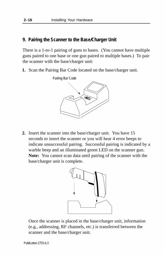
9. Pairing the Scanner to the Base/Charger Unit
There is a 1-to-1 pairing of guns to bases. (You cannot have multipleguns paired to one base or one gun paired to multiple bases.) To pairthe scanner with the base/charger unit:
1. Scan the Pairing Bar Code located on the base/charger unit.
Pairing Bar Code
2. Insert the scanner into the base/charger unit. You have 15seconds to insert the scanner or you will hear 4 error beeps toindicate unsuccessful pairing. Successful pairing is indicated by awarble beep and an illuminated green LED on the scanner gun.Note: You cannot scan data until pairing of the scanner with thebase/charger unit is complete.
Once the scanner is placed in the base/charger unit, information(e.g., addressing, RF channels, etc.) is transferred between thescanner and the base/charger unit.
�������
Publication 2755-6.3
���� �� �� ��� �������
This chapter describes the configuration options for the scanners.Included are:
• important notes on configuring a scanner
• available symbologies
• scanner bar codes
• scanner default settings
• parameter selections
• parameter descriptions
• configuration sequence
Important Notes on Configuring a Scanner
Be aware of the following when configuring the scanner:
• The scanner bar codes are located in the Hand-Held Cordless BarCode Scanners Programming Guide (Publication No. 2755-6.6).
• The scanner may be configured with default values, see page 3–3. If the default values are suitable for your application,scan the Set Defaults bar code.
3–2 Configuring Your Scanner
Publication 2755-6.3
Available Symbologies
The scanner automatically discriminates between all of the followingsymbologies. The only exception is that the scanner cannotdiscriminate between Code 39 and Code 39 Full ASCII (see glossarydefinition). The scanner can read and decode these symbologies:
• UPC-A
• UPC-E
• Code 39 Full ASCII
• Code 39
• Code 128
• EAN 8
• EAN 13
• EAN 128
• Codabar
• Interleaved 2 of 5
• Discrete 2 of 5
• MSI Plessey
All bar code symbologies are enabled as the default. To disable asymbology, scan the Delete bar code. To enable a symbology, scanthe Add bar code for the symbology.
Scanner Bar Codes
All programming codes may be found in the Hand-Held CordlessBar Code Scanners Programming Guide (Publication No. 2755-6.6).The scanner is always enabled to read Code 128 labels since allconfiguration codes use this symbology.

Configuring Your Scanner 3–3
Publication 2755-6.3
Scanner Default Settings
The following table lists the default settings for the standard andextended range scanners.
Description Default Setting
Host Interface None
Code Types All Enabled
Code Lengths
Code 39 1 to 55
Code 128 3 to 55
Codabar 2 to 55
I 2 of 5 14
D 2 of 5 14
MSI Plessey 1 to 55
Decode Options
Transmit UPC-A Check Digit Enabled
Transmit UPC-E Check Digit Enabled
Convert UPC-E to UPC-A Disabled
EAN Zero Extend Disabled
Transmit No Decode Message Disabled
Decode UPC/EAN Supplemental Disabled
ITF-14/EAN-13 Conversion Enabled
Transmit Code 39 Check Digit Disabled
MSI Plessey Check Digit 1
Buffer Code 39 Disabled
Beeper Volume High
Table continued on the next page.

3–4 Configuring Your Scanner
Publication 2755-6.3
Description Default Setting
Beep After Good Decode Enabled
UPC/EAN Security Level 0
Decode Redundancy 0
UPC-A Preamble System Character
UPC-E Preamble System Character
Pause Duration 0
Prefix Value None
Suffix Value 7013 ( <Enter> for wedges,<CR/LF> for serial devices)
Scan Data Transmission Format Data As Is
Laser Control
Laser On Time-Out 3 Seconds
RS-232C Options
Baud Rate 9600
Parity Odd
Check Parity Enabled
Hardware Handshaking None
Software Handshaking None
Serial Response Time-out 2 Seconds
Stop Bit Select 2
ASCII Data Format 7-bit
RTS Line State Low
Intercharacter Delay 0
Transmit Code ID Character Disabled
Transmit AIM Code ID Disabled
Ignore Unknown Characters Enabled
International Keypad Emulation Disabled
Table continued on the next page.
Configuring Your Scanner 3–5
Publication 2755-6.3
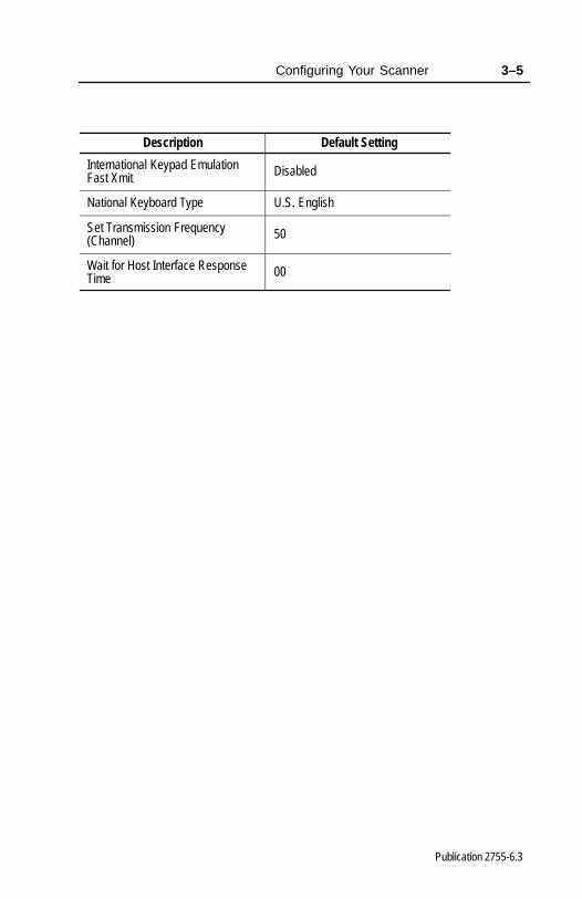
Description Default Setting
International Keypad EmulationFast Xmit Disabled
National Keyboard Type U.S. English
Set Transmission Frequency(Channel) 50
Wait for Host Interface ResponseTime 00
3–6 Configuring Your Scanner
Publication 2755-6.3
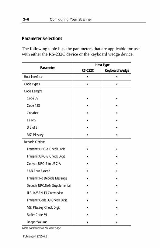
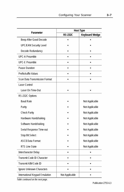
Parameter Selections
The following table lists the parameters that are applicable for usewith either the RS-232C device or the keyboard wedge device.
Host TypeParameter
RS-232C Keyboard Wedge
Host Interface • •
Code Types • •
Code Lengths
Code 39 • •
Code 128 • •
Codabar • •
I 2 of 5 • •
D 2 of 5 • •
MSI Plessey • •
Decode Options
Transmit UPC-A Check Digit • •
Transmit UPC-E Check Digit • •
Convert UPC-E to UPC-A • •
EAN Zero Extend • •
Transmit No Decode Message • •
Decode UPC/EAN Supplemental • •
ITF-14/EAN-13 Conversion • •
Transmit Code 39 Check Digit • •
MSI Plessey Check Digit • •
Buffer Code 39 • •
Beeper Volume • •Table continued on the next page.
Configuring Your Scanner 3–7
Publication 2755-6.3
Host TypeParameter
RS-232C Keyboard Wedge
Beep After Good Decode • •
UPC/EAN Security Level • •
Decode Redundancy • •
UPC-A Preamble • •
UPC-E Preamble • •
Pause Duration • •
Prefix/suffix Values • •
Scan Data Transmission Format • •
Laser Control
Laser On Time-Out • •
RS-232C Options
Baud Rate • Not Applicable
Parity • Not Applicable
Check Parity • Not Applicable
Hardware Handshaking • Not Applicable
Software Handshaking • Not Applicable
Serial Response Time-out • Not Applicable
Stop Bit Select • Not Applicable
ASCII Data Format • Not Applicable
RTS Line State • Not Applicable
Intercharacter Delay • •
Transmit Code ID Character • •
Transmit AIM Code ID • •
Ignore Unknown Characters • •
International Keypad Emulation Not Applicable •Table continued on the next page.

3–8 Configuring Your Scanner
Publication 2755-6.3
Host TypeParameter
RS-232C Keyboard Wedge
International Keypad EmulationFast Xmit Not Applicable •
National Keyboard Type • •
Set Transmission Frequency(Channel) • •
Wait for Host Interface ResponseTime • •
Parameter Descriptions
The following sections describe the parameters that can be used witheither the RS-232C device or the keyboard wedge device.
Host Interface Code
Allows you to select the host device.
Code types
Allows you to select the appropriate bar code symbology.
Code 39 Full ASCII
Allows you to assign a code for letters, punctuation marks, numerals,and most keys on the keyboard.
The first 32 codes are non-printable and are assigned to keyboardcontrol characters such as backspace and return. The other 96 codesare printable codes except for space and delete.
Code 39 Full ASCII interrupts the bar code control character ($+%/)preceding a code 39 symbol and assigns an ASCII character. Forexample, when code 39 Full ASCII is enabled and a +B is scanned,the equivalent is b.

Configuring Your Scanner 3–9
Publication 2755-6.3
Code 39 Any Length
Allows you to decode a Code 39 symbol containing any number ofcharacters.
Code 39 Length Within Range
Allows you to decode a Code 39 symbol within a specified range ofcharacters.
Code 39 One Length
Allows you to decode a Code 39 symbol containing a selected lengthof characters.
Code 39 Two Lengths
Allows you to decode a Code 39 symbol containing two selectedlengths of characters.
Code 128 Any Length
Allows you to decode a Code 128 symbol containing any number ofcharacters.
Codabar Any Length
Allows you to decode a Codabar symbol containing any number ofcharacters.
Codabar Length Within Range
Allows you to decode a Codabar symbol within a specified range ofcharacters.
Codabar One Length
Allows you to decode a Codabar symbol containing a selected lengthof characters.
3–10 Configuring Your Scanner
Publication 2755-6.3
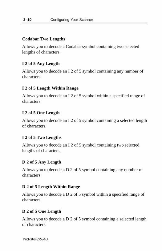
Codabar Two Lengths
Allows you to decode a Codabar symbol containing two selectedlengths of characters.
I 2 of 5 Any Length
Allows you to decode an I 2 of 5 symbol containing any number ofcharacters.
I 2 of 5 Length Within Range
Allows you to decode an I 2 of 5 symbol within a specified range ofcharacters.
I 2 of 5 One Length
Allows you to decode an I 2 of 5 symbol containing a selected lengthof characters.
I 2 of 5 Two Lengths
Allows you to decode an I 2 of 5 symbol containing two selectedlengths of characters.
D 2 of 5 Any Length
Allows you to decode a D 2 of 5 symbol containing any number ofcharacters.
D 2 of 5 Length Within Range
Allows you to decode a D 2 of 5 symbol within a specified range ofcharacters.
D 2 of 5 One Length
Allows you to decode a D 2 of 5 symbol containing a selected lengthof characters.

Configuring Your Scanner 3–11
Publication 2755-6.3
D 2 of 5 Two Lengths
Allows you to decode a D 2 of 5 symbol containing two selectedlengths of characters.
MSI Plessey Any Length
Allows you to decode an MSI Plessey symbol containing anynumber of characters.
MSI Plessey Length Within Range
Allows you to decode an MSI Plessey symbol within a specifiedrange of characters.
MSI Plessey One Length
Allows you to decode an MSI Plessey symbol containing a selectedlength of characters.
MSI Plessey Two Lengths
Allows you to decode an MSI Plessey symbol containing twoselected lengths of characters.
Transmit UPC-A Check Digit
Decoded UPC-A symbol data is transmitted with or without thecheck digit.
Transmit UPC-E Check Digit
Decoded UPC-E symbol data is transmitted with or without thecheck digit.
3–12 Configuring Your Scanner
Publication 2755-6.3
Convert UPC-E to UPC-A
When enabled, this option converts UPC-E (zero suppressed)decoded data to a UPC-A format before sending the data. Afterconversion, output data will be affected by UPC-A programmingselections such as preamble and check digit settings.
EAN Zero Extend
When enabled, five leading zeros are added to decoded EAN 8symbol data. The five zeros make the EAN 8 symbols compatiblewith the EAN 13 format.
Transmit No Decode Message
When enabled, a NR is transmitted with each no-read. Prefixes andsuffixes appear with the output message.
UPC / EAN Supplemental
When enabled, supplemental digits are decoded. If the supplementaldigits are not enabled and a bar code having supplemental digits isread, the supplemental digits are ignored. On the other hand, ifsupplemental digits are enabled, only bar codes with supplementaldigits are decoded.
I 2 of 5 (14 digit) to EAN 13 Conversion
When enabled, 14 character Interleaved 2-of-5 data is converted andtransmitted to the host in an EAN 13 format. The I 2 of 5 code mustbe enabled, have one length set to 14, have a leading zero, and havea valid EAN-13 check digit.
Code 39 Check Digit
When enabled, the scanner verifies the Code 39 check digit (modulo 43 check character).
Configuring Your Scanner 3–13
Publication 2755-6.3
MSI Plessey check Digit
When enabled, one or two digits at the end of the bar code thatchecks the integrity of that data.
Code 39 Buffering (Scan and Store)
When enabled, the scanner stores all Code 39 symbol data that has aleading space as the first character. As Code 39 labels are scannedfor buffering, the scanner provides a high/low beep to indicate thatthe data is stored in the buffer. The leading space is not stored in thebuffer.
Decoding of a valid Code 39 symbol with no leading space causestransmission in sequence of all buffered data in a first-in, first-outbasis, plus transmission of the triggering symbol.
If you select the scan and transmit option, decoded Code 39 symbolswithout leading spaces are transmitted without being stored in thebuffer.
Scan and Store affects Code 39 decodes only. If you select Scan andstore, it is recommended that you configure the scanner to decodeCode 39 symbology only.
Up to 250 bytes of information may be stored. If you scan a symboland the buffer is full, the scanner will provide three long high tonebeeps. No transmission will occur and the data in the buffer is notaffected.
Note: Before you can disable Code 39 buffering, you must clear thebuffer.
Beeper Volume
Allows you to select the level of beeper volume.

3–14 Configuring Your Scanner
Publication 2755-6.3
Beep After Good Decode
When enabled, the scanner will beep during normal operation. Thebeeper operates during parameter menu scanning and indicates errorconditions. It is recommended that you leave this option enabled.
UPC / EAN Security Level
There are four levels of decode security. There is an inverserelationship between security and the ability to decode codes ofvarying quality. Increasing levels of security are provided fordecreasing levels of bar code quality. Select one of the levels below.
The default security level is 0. This level is sufficient for mostapplications. Higher security levels:
• may result in more no-reads on poor quality labels
• reduce the chance of mis-reads on poor quality labels
Security Level Decode Operation
0The scanner decodes many poor or low quality bar codes whileproviding adequate security for UPC/EAN codes within specifications.This is the default setting.
1As quality level of UPC / EAN bar codes decrease, certain digits aremore susceptible to misreads ( 1, 2, 7, 8) If you have problemsdecoding bar codes with these digits, select this security level.
2 If you are having problems decoding poor quality bar codes and theproblem isn’t limited to the digits ( 1, 2, 7, 8), select this level.
3
If you selected security level 2 and are still having problems decodingsymbols, select this security level.Note: Only use this level if you are scanning high quality bar codes.the scanner will reject codes that are not within the specifications forthe symbology.
Decode Redundancy
Use this parameter to indicate if a bar code is read one time (levelone), two times (level two), or three times (level three) beforedecoding it. Rereading a bar code helps ensure accuracy in decodingbar codes.

Configuring Your Scanner 3–15
Publication 2755-6.3
UPC-A / UPC-E Preambles
The UPC preamble consists of the system character and countrycode. The system character is the the first character on the left sideof the symbol. The country code for UPC is always 0. Selectwhether these characters are sent with the bar code data:
• system character only
• country code and system character
• no preamble
Note: There are separate preamble programming codes for bothUPC-A and UPC-E symbols.
Pause Duration
When enabled, this parameter allows you to insert a pause at anypoint in the data transmission. Pauses are set by scanning a two digitnumber (i.e., two bar codes, and are measured in 0.1 secondincrements).
Scan Prefix
To add prefix data to bar code data, scan the Prefix bar codefollowed by the 4 digit (decimal) ASCII equivalent value for eachcharacter. Only one character may be specified as a prefix. Whenyou enter the last digit of a prefix, the scanner lets you know that youhave entered a valid value by providing a high-low-high beep.
Scan Suffix
To add suffix data to bar code data, scan the Suffix bar code followedby the 4 digit (decimal) ASCII equivalent value for each character.Only one character may be specified as a suffix. When you enter thelast digit of a suffix, the scanner lets you know that you have entereda valid value by providing a high-low-high beep.

3–16 Configuring Your Scanner
Publication 2755-6.3
Data Transmission Formats
You can set whether or not prefix or suffix data is added to thedecoded symbol data. You have four options:
• <DATA AS IS> Only bar code data is sent. This is the defaultsetting.
• <DATA> <SUFFIX> Bar code data is sent, then the suffix data.
• <PREFIX><DATA><SUFFIX> Prefix data is sent, then barcode data followed by the suffix data.
• <PREFIX> <DATA> Prefix data is sent then the bar code data.
Laser On Time-Out
This setting determines the maximum time the scanner remains onwhile the trigger is pressed. The time-out is programmable in 0.5 second increments from 0.5 seconds to 3.0 seconds.
Baud Rate
Sets the rate (bits per second) at which the scanner transmits data.The scanner baud rate setting must match the host setting. If thesettings do not match, data may not reach the host device or reach itin distorted form. The selections are:
• 600
• 1200
• 2400
• 4800
• 9600 (default)
• 19200
Configuring Your Scanner 3–17
Publication 2755-6.3
Parity
Checks to ensure that the correct number of bits are contained in thecoded character. You can set the parity of each ASCII codedcharacter that is transmitted. Make sure the parity matches therequirements of the host. The selections are:
• Odd
• Even
• Mark (parity bit always set to 1)
• Space (parity bit always set to 0)
• None (Default)
Check Parity
When enabled, the scanner checks the received characters for parity.The type of parity can be selected with the Parity parameter. Thedefault parameter is Check Parity enabled.
Hardware Handshaking
When enabled, handshaking verifies the readiness of a receivingdevice before data is transmitted. If the receiving device isperiodically occupied with other tasks, hardware handshaking is usedto prevent loss of transmitted data. You can enable or disable thehardware handshaking lines, RTS (Request to Send), and CTS (Clearto Send). The DTR (Data Terminal Ready) signal is active high.Hardware handshaking cannot be used in conjunction with softwarehandshaking.
If RTS/CTS handshaking is enabled, the sequence for scanning datais:
1. The base/charger unit checks the Clear to Send (CTS) line. IfCTS is active, the base/charger unit will wait for up to one secondand check the line again. If the line is still active, thebase/charger unit will provide an audible beep and any scanneddata will be lost.
3–18 Configuring Your Scanner
Publication 2755-6.3
2. If the CTS line is not active, the base/charger unit will assert theRequest to Send (RTS) line and waits one second for the host toassert the CTS line. When the host asserts the CTS line, thebase/charger unit transmits the data. During the transmission ofdata, the CTS line should be asserted.
3. After the transmission is completed, the base/charger unit willnegate the RTS 10 msec after sending the last character.
4. The host device should then negate CTS. The base/charger unitchecks the CTS line on the next transmission.
If the sequence for scanning data fails, the base/charger unit issues atransmit error, indicating that the data is lost and must be rescanned.The default parameter is no Hardware Handshaking enabled.
Software Handshaking
Software handshaking controls the transmission of data. Usesoftware handshaking instead of (but not with) hardwarehandshaking. There are four options:
• None (Default)
• ACK/NAK Only
• ENQ Only
• ACK/NAK with ENQ
ACK/NAK Only checks the result of a transmission. Thebase/charger unit waits for one of the following responses from thehost:
• <ACK>
• <NAK>
ACK indicates a successful transmission. NAK indicates there is aproblem. Whenever the scanner receives a NAK, it retransmits thedata up to three times. If an ACK is still not received after threeattempts, the transmission is aborted and the scanner will providefour short beeps.
Configuring Your Scanner 3–19
Publication 2755-6.3
ENQ ONLY requires that the base/charger unit receive an an enquirecharacter (ENQ) from the host before sending data. With ENQenabled, the base/charger unit must receive an ENQ from the hostwithin a two second period after the last scan or a transmission erroroccurs. The scanner will provide four short beeps to indicate theerror; the base/charger unit is ready to send again.
ACK/NAK with ENQ combines both ACK/NAK and ENQ options.
Serial Response Time-out
When enabled, this parameter determines the maximum periodallowed to elapse before the base/charger unit assumes the end oftransmission. The delay can last up to 9.9 seconds. The defaultparameter is enabled at 2 seconds.
Stop Bit Select
The stop bit marks the end of each character transmitted andprepares the receiving device for the next character in the datastream. You can set the number of stop bits to either 1 or 2 to matchthe host device. The default parameter is set to 2.
ASCII Format
When enabled, the scanner transmits data in an 8-bit ASCII format.This allows the the base/charger unit to interface with devices usingthat protocol. The default is 7-bit ASCII.
RTS Line State
When enabled, the parameter adjusts the RTS Line State sincecertain hosts expect the RTS line to be in a certain state (high orlow). The default parameter is set to low.

3–20 Configuring Your Scanner
Publication 2755-6.3
Intercharacter Delay
When enabled, the host system has time to service its receiver andperform other tasks between characters. You can choose up to 99 msec delay between transmission of characters. The defaultparameter is set to zero.
Transmit Code ID Characters
The code ID identifies a scanned bar code symbol’s code type. Ifenabled, the code ID is sent after the prefix and before the bar codedata. The code ID codes are:
• A = UPC-A, UPC-E, or EAN 13
• B = Code 39
• C = Codabar
• D = Code 128
• E = Code 93
• F = Interleaved 2 of 5
• G = Discrete 2 of 5
The default parameter is disabled.
Transmit AIM Code ID
When enabled, the AIM code identifier is sent after the prefix andbefore the bar code data. The identifier is a three character prefix.Refer to AIM’s Guidelines on Symbology Identifiers for adescription. The default parameter is disabled.
Ignore Unknown Characters
When enabled, all data is sent except for unknown characters and noerror beeps are sounded. Unknown characters are those charactersthat the host device does not recognize. When disabled, all datacontaining one or more unknown characters is discarded and errorbeeps are sounded. The default parameter is enabled.

Configuring Your Scanner 3–21
Publication 2755-6.3
International Keyboard Emulation
When enabled, this parameter allows you to send the code from thetype of keyboard that you have. This parameter will allow you toselect a national keyboard type. This parameter is supported by IBMAT/XT/PS2 computers only. The default parameter is disabled.
International Keyboard Emulation Fast Transmit
When enabled, this parameter allows you to send the code from thetype of keyboard that you have quickly. This parameter will allowyou to select a national keyboard type. This parameter is supportedby some IBM AT/XT/PS2 computers only. The default parameter isdisabled.
National Keyboard Type
Allows you to set the national character type for the keyboard youare using. Selections include U.S. English, French, German, French International, Spanish, Italian, Swedish, and U.K. English.The default parameter is set to U.S. English.
Set Transmission Frequency
Allows you to set the transmission channel of communicationbetween the scanner gun and the base/charger unit. The defaultparameter is set to 50.
Wait for Host Interface Response Time
The scanning system automatically calculates the time it takes forbase/charger unit to communicate with the host device and for thebase/charger unit to send an acknowledgement back to the scanner.Under normal operating conditions, you should not enable this barcode option.
If you need to enable this option, the timeout values can range from1 to 99 seconds. If you receive error beeps while enabling this barcode, increase the timeout value until the error beeps stop. Thedefault parameter is set to 00.
3–22 Configuring Your Scanner
Publication 2755-6.3
Configuration Sequence
To configure the scanner:
1. Connect the base/charger unit to the host device. Refer toChapter 2 for more information.
2. Make sure the scanner gun has a fully charged battery. Refer toChapter 2 for more information.
3. Pair the scanner to the base/charger unit. Refer to Chapter 2 formore information.
4. Decide if the default values meet your requirements. Refer topage 3–3 for a listing of the default parameters. If the defaultvalues meet your requirements, scan the Set Defaults bar codelocated in the Hand-Held Cordless Bar Code ScannersProgramming Guide (Publication No. 2755-6.6). If the defaultparameters do not meet your requirements, scan the appropriatebar codes for the options you need found in the Hand-HeldCordless Bar Code Scanners Programming Guide (PublicationNo. 2755-6.6). It is recommended that you scan the Set Defaultsbar code before entering any additional bar codes. The scannerparameters may be configured in any sequence.

������� �
Publication 2755-6.3
������� ������ ��
This chapter describes scanner operation. Included are sections on:
• important notes on using your scanner
• testing your scanner
• scanning bar codes
Important Notes on Using Your Scanner
Before using your scanner for data collection, make sure:
• the base/charger unit is connected to the host device,
• the power supply is connected to the base/charger unit,
• the battery is charged, and
• the scanner is paired with the base/charger unit.
Testing Your Scanner
Before using your scanner in an actual application, test the scanner tomake sure it is functioning properly. Aim the scanner at a slightangle towards a test bar code found on the inside back cover of thismanual and press the trigger. You should see the scan beam on thebar code and the red LED on the back of the scanner should be on.If you have a successful read, the green LED on the back of the gunturns on and remains on until the next scan (trigger pressed). Referto page 5–13 if the scanner did not function properly.
4–2 Scanner Operation
Publication 2755-6.3
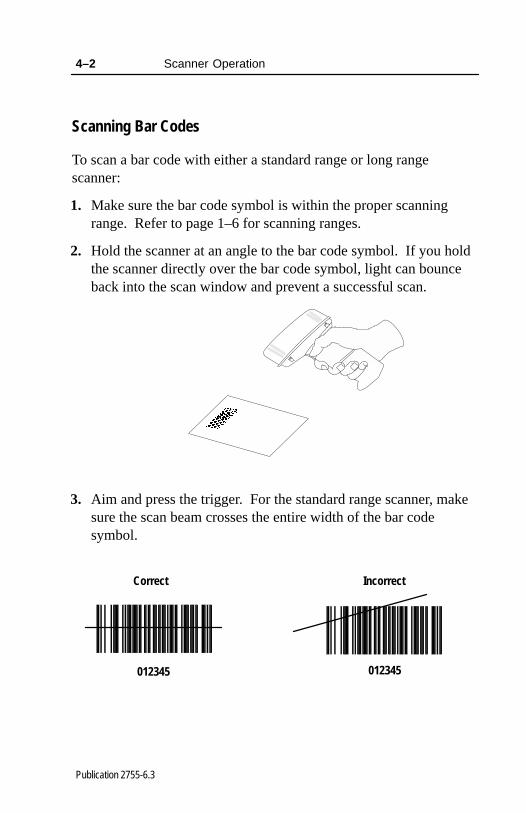
Scanning Bar Codes
To scan a bar code with either a standard range or long rangescanner:
1. Make sure the bar code symbol is within the proper scanningrange. Refer to page 1–6 for scanning ranges.
2. Hold the scanner at an angle to the bar code symbol. If you holdthe scanner directly over the bar code symbol, light can bounceback into the scan window and prevent a successful scan.
3. Aim and press the trigger. For the standard range scanner, makesure the scan beam crosses the entire width of the bar codesymbol.
Correct Incorrect
012345 012345

Scanner Operation 4–3
Publication 2755-6.3
For the long range scanner, you need to press the trigger partiallyto center the aiming beam on the bar code and then press thetrigger fully to emit the full width scanning beam on the bar code.
Correct Incorrect
012345 012345
Correct Incorrect
012345 012345
First Trigger Position
Second Trigger Position
For both scanners, you should see the scan beam across the barcode and the red LED on the back of the scanner should be on. Ifthe scanner has made a successful read, you will hear one beepand the green LED on the back of the scanner turns on. Thegreen LED stays on for up to one second if the the trigger is downor until you release the trigger. If the scanner has made anunsuccessful attempt to read the bar code, you will hear 4 errorbeeps. Refer to Troubleshooting on page 5–13 for moreinformation regarding scanning errors.

������� �
Publication 2755-6.3
�� �������� ���
���������� ��
This chapter describes how to maintain and troubleshoot thescanners. Topics include:
• charging the battery
• conditioning the battery
• changing the battery pack in the scanner gun
• cleaning the scan window
• troubleshooting the scanners
• troubleshooting the 4-slot battery charger
• listening for audible responses
• contacting Allen-Bradley Global Technical Services
5–2 Maintenance and Troubleshooting
Publication 2755-6.3
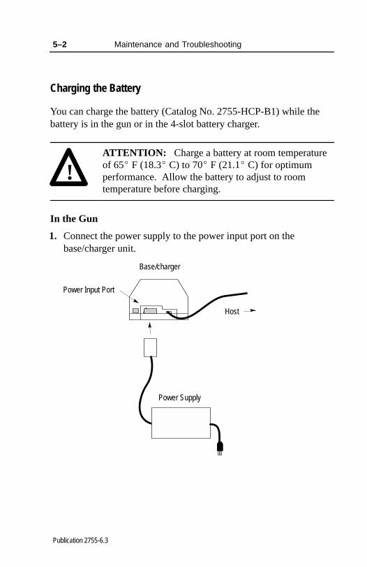
Charging the Battery
You can charge the battery (Catalog No. 2755-HCP-B1) while thebattery is in the gun or in the 4-slot battery charger.
!ATTENTION: Charge a battery at room temperatureof 65� F (18.3� C) to 70� F (21.1� C) for optimumperformance. Allow the battery to adjust to roomtemperature before charging.
In the Gun
1. Connect the power supply to the power input port on thebase/charger unit.
Base/charger
Host
Power Supply
Power Input Port

Maintenance and Troubleshooting 5–3
Publication 2755-6.3
2. Connect the power supply to the appropriate receptacle supplyingAC power of the proper voltage level.
Power Supply Voltage Level
2755-HCP-D1 100–240V ac/50–60 Hz
3. Place the scanner into the base/charger unit as shown below.Make sure that the unit fits snugly into the base/charger.
4. Check the charge status indicator for a full charge (blinkingrapidly = full charge), which occurs within two hours. However,you can use the scanner with less than a full charge.
Charge Status LED

5–4 Maintenance and Troubleshooting
Publication 2755-6.3
Base/charger LED Status
Red LED Indicates
Off
The scanner is not properlyinserted into the base/chargerunit or the battery is notfunctioning properly.
Blinking Slowly
Battery charge is pending.This occurs if the batterytemperature is too high or toolow or the battery is deeplydischarged. After severalminutes, normal chargingshould begin.
OnThe battery is activelycharging. Charging takesapproximately two hours.
Blinking Rapidly Battery charging is complete.
Refer to page 5–13 for more information regarding low batterystrength.
Average life of a battery charge is 8 hours. Refer to page 5–10 forreplacing the battery.
Maintenance and Troubleshooting 5–5
Publication 2755-6.3
In the 4-Slot Battery Charger
Before using the 4-slot battery charger (Catalog No. 2755-HCP-B2),read all the instructions and cautionary markings on the 4-slot batterycharger, battery, and on any products that use the battery.
!ATTENTION: To reduce the risk of injury, use the4-slot battery charger only in the way it is intended tobe used. Other batteries or adapters may explodecausing personal injury and damage.
To help insure proper operation of the 4-slot battery charger andbatteries, refer to the following.
• Do not expose the battery charger to rain, snow, or direct sunlight.
• The battery charger can be used at 32� F to 104� F (0� C to 40� C).
• The battery charger should be placed in a well ventilated area freeof airborne contaminants.
• Unplug the battery charger from the receptacle supplying ACpower before attempting to clean or change adapters in order toreduce the risk of electrical shock.
• Dispose of dead batteries in accordance with all applicable codes.
• Do not disassemble, incinerate, modify, or short circuit batteries,charger, or related components.
• Perform a battery conditioning cycle on all new NiCd batteriesbefore using to ensure that the battery is fully charged. Refer topage 5–9 to condition a battery.
To charge the battery in the 4-slot battery charger:
1. Mount the 4-slot battery charger horizontally as shown below.
5–6 Maintenance and Troubleshooting
Publication 2755-6.3
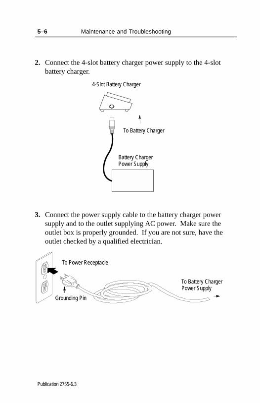
2. Connect the 4-slot battery charger power supply to the 4-slotbattery charger.
Battery Charger Power Supply
4-Slot Battery Charger
To Battery Charger
3. Connect the power supply cable to the battery charger powersupply and to the outlet supplying AC power. Make sure theoutlet box is properly grounded. If you are not sure, have theoutlet checked by a qualified electrician.
To Power Receptacle
To Battery Charger Power Supply
Grounding Pin

Maintenance and Troubleshooting 5–7
Publication 2755-6.3
The power supply manages and conditions the power input to thecharger, eliminating the need for a replaceable fuse. Should apower surge occur, the power supply connected to the chargertemporarily interrupts the current supply until the condition iscorrected. If an extreme surge occurred, the power light on thepower supply remains off and the power supply needs to bereplaced.
4. Attach the battery adapter (Catalog No. 2755-HCP-B3) to thebattery charger by aligning the adapter to the charger and slidingthe adapter downward, locking into place.
4-Slot Battery Charger
Battery Adapter
To remove the adapter, push the tab up and slide the adapteroutward.
Tab
4-Slot Battery Charger

5–8 Maintenance and Troubleshooting
Publication 2755-6.3
5. Insert a depleted battery into an adapter that is inserted into the4-slot battery charger. Press the handle release button in as youare sliding the battery into the adapter.
4-Slot Battery Charger
Battery Adapter
Battery
Handle Release Button
Charging Station
If you are charging a new battery pack, the battery charger mayprematurely switch to ready. If this occurs, remove the battery fromthe adapter and reinsert.
Upon completion of a battery charge, the READY LED on thebattery charger will flash. This indicates the battery is 95% charged.For 100% charge, leave the battery on the charger for 3 hours. Afully charged battery can be left on the battery charger indefinitely.The battery charger maintains the battery at 100% of its ratedcapacity.
Maintenance and Troubleshooting 5–9
Publication 2755-6.3
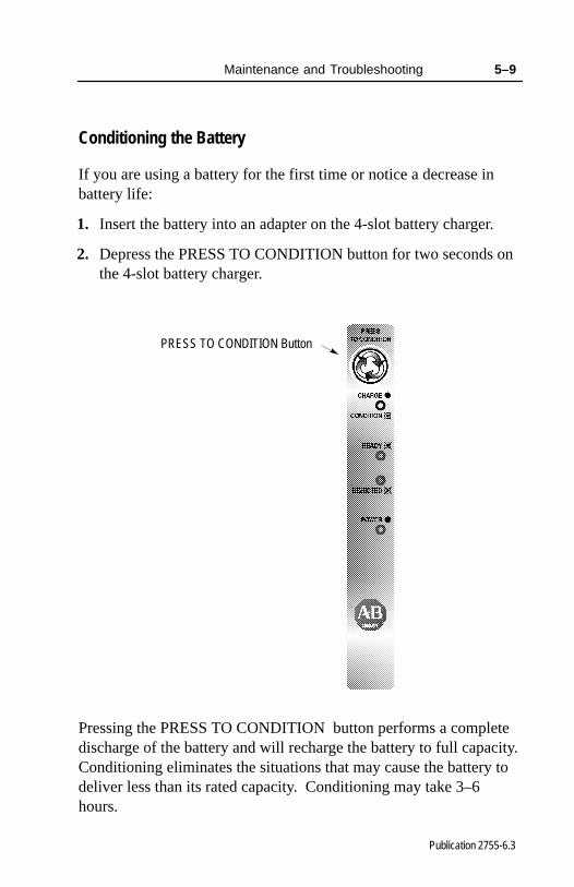
Conditioning the Battery
If you are using a battery for the first time or notice a decrease inbattery life:
1. Insert the battery into an adapter on the 4-slot battery charger.
2. Depress the PRESS TO CONDITION button for two seconds onthe 4-slot battery charger.
PRESS TO CONDITION Button
Pressing the PRESS TO CONDITION button performs a completedischarge of the battery and will recharge the battery to full capacity.Conditioning eliminates the situations that may cause the battery todeliver less than its rated capacity. Conditioning may take 3–6hours.

5–10 Maintenance and Troubleshooting
Publication 2755-6.3
!ATTENTION: Perform the conditioning cycle whenthe battery is new or shows decreased life.Conditioning batteries more often will shorten batterylife.
If conditioning the battery is not successful as indicated by theflashing REJECTED indicator on the battery charger, your batteryneeds replacement. Contact your local Allen-Bradley distributor forordering a new battery.
Changing the Battery Pack in the Scanner Gun
1. Locate the handle release button on the scanner.
Battery PackHandle Release Button
2. Press in the handle release button below the outer housing with aprobe.

Maintenance and Troubleshooting 5–11
Publication 2755-6.3
3. Slide the battery pack out from the handle.
Battery PackHandle Release Button
4. Insert the new battery into the scanner handle. Make sure thehandle release button is pressed in below the outer housing whensliding a charged battery into place.
5. Pair the scanner with the base/charger unit. Refer to page 2–16for information regarding pairing the scanner to the base/chargerunit.
5–12 Maintenance and Troubleshooting
Publication 2755-6.3
Cleaning the Scan Window
Carefully clean the window by first removing loose particles of dirtwith clean air. Then use an optical quality cloth moistened with anoptical quality cleaning fluid for plastic lenses and wipe the windowin a single direction (don’t wipe cloth back and forth acrosswindow). Do not leave streaks.
!ATTENTION: Do not use abrasive materials such asdisposable wipes and facial tissue. Do not use solventslike alcohol or acetone. These materials will damagethe window and the finish on the scanner.
!ATTENTION: The scanner has no serviceable parts.Do not open the housing of the scanner.

Maintenance and Troubleshooting 5–13
Publication 2755-6.3
Troubleshooting the Scanners
The following table provides a list of the most common operatingproblems, the probable causes, and suggested corrective actions.
Problem Probable Cause(s) Corrective Action
1. Power supply notconnected to base/chargerunit or power source.
1. Make sure power supply isconnected to thebase/charger unit andplugged into a powersource.
2. Depleted battery. 2. Recharge battery.
No Scan Beam 3. Scan beam has timed out. 3. Normal operation. Releasetrigger completely andscan again.
4. Defective scanner. 4. If possible, try anotherscanner using the sameconnections. ContactAllen-Bradley GlobalTechnical Services (GTS).
Weak Scan Beam 1. Depleted battery. 1. Recharge battery.
Scan Beam Appears as aDot, Not a Line
1. Trigger on long rangescanner is not fullypressed.
1. Long range scanner has a2 position trigger. The firstposition is for the spotterbeam. Press the trigger tothe next position forscanning.
2. Defective scanner. 2. Contact Allen-BradleyGlobal Technical Services(GTS).
Table continued on the next page.

5–14 Maintenance and Troubleshooting
Publication 2755-6.3
Problem Probable Cause(s) Corrective Action
Scan Beam Present,Bar Codes Not Read
1. Scanner and base/chargerunit are not paired.
2. Scanner out oftransmission range.
3. Scanner not held at slightangle to the bar code.
4. Scanner not programmedto read the type of barcode you are scanning.
5. Scan beam not crossingentire symbol.
6. Poor quality bar codesymbols.
7. Loose cable connections.
1. Pair the scanner andbase/charger unit together.
2. Move scanner closer tobase/charger unit.
3. Hold scanner at an angleto the bar code.
4. Make sure the scanner isconfigured for the type ofbar code symbols you arescanning.
5. Make sure scan beamcrosses every bar or spaceon the symbol.
6. Use the symbols providedon the inside back coverfor testing.
7. Check for loose cables/improper connections.

Maintenance and Troubleshooting 5–15
Publication 2755-6.3
Troubleshooting the 4-Slot Battery Charger
The following LEDs and tables provide you with informationregarding troubleshooting the 4-slot battery charger.
4-Slot Battery Charger LED Status
Each charging station has its own status display to inform you of thestation’s status as shown below.
LED Color Status Indicates
Solid Battery is charging.Charge Yellow
Flashing Battery is conditioning.
Ready Green Flashing Station has charged batteryto 95% capacity.
Rejected Red Flashing Faulty battery.
Power Green Solid Power is applied to batterycharger.

5–16 Maintenance and Troubleshooting
Publication 2755-6.3
Identifying 4-Slot Battery Charger Errors
The following table provides a list of the most common operatingproblems, the probable causes, and suggested corrective actions.
Problem Probable Cause(s) Corrective Action
1. Power supply cord is notconnected to powerreceptacle.
1. Check connection.
Power Indicator on BatteryCharger is Not Lit (all
2. Power supply cord notconnected to the batterycharger.
2. Check connection.
stations)3. Faulty power supply or
4-slot battery charger.3. Replace the power supply
or the 4-slot batterycharger. ContactAllen-Bradley GlobalTechnical Services (GTS).
Power Indicator on Battery1. Faulty charging station. 1. Use a different charging
station.Charger is Not Lit (singlestation) 2. Faulty LED. 2. Use a different charging
station.
1. Faulty condition identified. 1. Remove battery from thebattery adapter. Reinsertthe battery adapter into thebattery charger.
Station Rejected Indicator isLit (red flashing)
2. Over discharge of batteryoccurred.
2. Allow battery adapter to sitin the battery charger for15 minutes and thenreinsert the battery intothat battery adapter.
3. Defective battery. 3. Replace the battery.
1. Battery is fully charged. 1. None needed.Station is Ready in a ShortPeriod of Time 2. Faulty battery. 2. Recharge or replace the
battery.
Table continued on the next page.

Maintenance and Troubleshooting 5–17
Publication 2755-6.3
Problem Probable Cause(s) Corrective Action
1. Battery charger is notseated properly on thebattery charger.
1. Reseat the batteryadapter.
2. Defective battery adapter. 2. Replace the batteryadapter.
Station will not go into ChargeMode (yellow solid indicator)
3. Defective battery. 3. Replace the battery.Mode (yellow solid indicator)
4. Battery is not the propertemperature.
4. Allow the battery adjust toroom temperature.
5. Faulty LED on batterycharger.
5. Contact Allen-BradleyGlobal Technical Services(GTS).
1. Battery is too hot. 1. Allow battery to cool down.
Station will not go intoCondition Mode (yellow
2. Battery is alreadydischarged.
2. Charge battery.
Condition Mode (yellowflashing indicator) 3. Faulty LED. 3. Contact Allen-Bradley
Global Technical Services(GTS).
Battery Becomes Hot 1. Battery is defective. 1. Replace batteryimmediately.
Power Supply Shuts DownTemporarily
1. Power line surge. 1. Power is automaticallyreset.

5–18 Maintenance and Troubleshooting
Publication 2755-6.3
Listening for an Audible Response
When scanning a bar code symbol, you hear beeps from the scanner.Refer to the following tables to determine the meaning of the beeps.
Beep During Normal Operation
This Response Indicates
1 Beep (short–high tone) Bar code symbol is decoded. Scanneraudible response must be enabled.
2 Beeps (long–high tone) Mismatch between the selected host andinterface cable.
4 Beeps (long–high tone)Format or transmission error detected. Thiserror occurs if the scanner is not properlyconfigured. Verify option settings.
5 Beeps (long–high tone)
Data conversion error detected. This erroroccurs if the Ignore Unknown Characters isdisabled when attempting to transmit data notsupported by the selected host.
6 Beeps (short–low tone) RF out of range error detected. The scan didnot register with the base/charger unit.
Beep During Entering Parameter Bar Codes
This Response Indicates
1 Beep (short–high tone) Bar code symbol is accepted. Scanneraudible response must be enabled.
1 Beep (low–high tone)
Input error. Possible causes:• Incorrect bar code scanned• Cancel scanned• Incorrect configuration sequence
1 Beep (high–low tone) Keyboard parameter selected. Scan theappropriate bar code.
1 Beep (high–low–high–low tone) Successful program exit with change in theparameter setting.
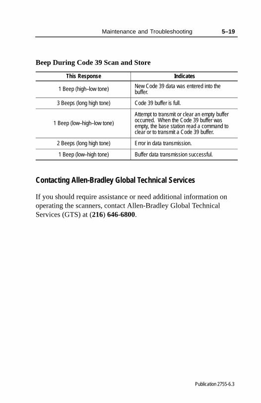
Maintenance and Troubleshooting 5–19
Publication 2755-6.3
Beep During Code 39 Scan and Store
This Response Indicates
1 Beep (high–low tone) New Code 39 data was entered into thebuffer.
3 Beeps (long high tone) Code 39 buffer is full.
1 Beep (low–high–low tone)
Attempt to transmit or clear an empty bufferoccurred. When the Code 39 buffer wasempty, the base station read a command toclear or to transmit a Code 39 buffer.
2 Beeps (long high tone) Error in data transmission.
1 Beep (low–high tone) Buffer data transmission successful.
Contacting Allen-Bradley Global Technical Services
If you should require assistance or need additional information onoperating the scanners, contact Allen-Bradley Global TechnicalServices (GTS) at (216) 646-6800.
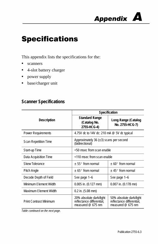
�������
Publication 2755-6.3
���� � ��� ��
This appendix lists the specifications for the:
• scanners
• 4-slot battery charger
• power supply
• base/charger unit
Scanner Specifications
Specification
DescriptionStandard Range
(Catalog No.2755-HCG-4)
Long Range (CatalogNo. 2755-HCG-7)
Power Requirements 4.75V dc to 14V dc: 210 mA @ 5V dc typical
Scan Repetition Time Approximately 36 (±3) scans per second(bidirectional)
Start-up Time <50 msec from scan enable
Data Acquisition Time <110 msec from scan enable
Skew Tolerance ± 55� from normal ± 60� from normal
Pitch Angle ± 65� from normal ± 45� from normal
Decode Depth of Field See page 1–6 See page 1–6
Minimum Element Width 0.005 in. (0.127 mm) 0.007 in. (0.178 mn)
Maximum Element Width 0.2 in. (5.08 mm)
Print Contrast Minimum20% absolute dark/lightreflectance differential,measured @ 675 nm
50% absolute dark/lightreflectance differential,measured @ 675 nm
Table continued on the next page.

A–2 Specifications
Publication 2755-6.3
DescriptionStandard Range
(Catalog No.2755-HCG-4)
Long Range (CatalogNo. 2755-HCG-7)
Frequency Control Programmable Synthesizer
Frequency Range 2.4 to 2.5G Hz
Frequency Resolution 250K Hz steps
Frequency Stability ± 20 ppm
Conducted RF Power Output 10 dBm
Radiated RF Power 1 mW (<50 mV/m @3m)
Output Bandwidth 250K Hz @ – 3 dB500K Hz @ – 20 dB
Ambient Light Immunity
Artificial Lighting 450 ft candles (4844 lux)
Sunlight 8000 ft candles (86112 lux @8 in. onlow density bar codes)
8000 ft candles (86112 lux)
Durability 6 ft (8 m) drop to concrete
Operating Temperature 32� F to 104� F (0� C to 40� C)
Storage Temperature -40� F to 140� F (-40� C to 60� C)
Humidity 5 to 95% noncondensing
Height 6.3 in. (16 cm)
Length 5 in. (12.7 cm)
Width 2.8 in. (7.1 cm)
CDRH Class I, II II
Agency Certification • CSA certified• UL listed

Specifications A–3
Publication 2755-6.3
4-Slot Battery Charger Specifications
Description Specification
Catalog Number 2755-HCP-B2
Operating Temperature 32� F to 104� F (0� C to 40� C)
Storage Temperature -40� F to 140� F (-40� C to 60� C)
Humidity 5 to 95% noncondensing
Agency Certification• cUL listed• UL listed• TUV EN 60950 approved
Power Supply Specifications
Description Specification
Catalog Number 2755-HCP-D1
Input Range 100–240V ac/50–60 Hz
Output Range 5V dc @ 3 A12V dc @ 1 A
Operating Temperature 32� F to 104� F (0� C to 40� C)
Agency Certification
• CSA certified• UL listed• CE marked for all applicable directives.• TUV EN 60950 approved

A–4 Specifications
Publication 2755-6.3
Base/Charger Unit Specifications
Description Specification
Catalog Number 2755-HCG-B
5V dc ± 10% @ 190 mA typicalPower Requirements 5V dc ± 10% @ 190 mA typical12V dc ± 10% 400 mA typical
Sensitivity –94 dBm 10E–4 BER
Selectivity 250K Hz @3 dB points1 MHz @ 50 dB points
Frequency Control Programmable Synthesizer
Frequency Range 2.4 to 2.5G Hz
Frequency Resolution 250K Hz steps
Frequency Stability ± 20 ppm
Durability 6 ft (8 m) drop to concrete
Operating Temperature 32� F to 104� F (0� C to 40� C)
Storage Temperature -40� F to 140� F (-40� C to 60� C)
Humidity 5 to 95% noncondensing
Agency Certification • CSA certified• UL listed
������� �
Publication 2755-6.3
����� � ���
This appendix provides the pinouts for the following cables:
• RS-232-C, 25-pin DB, male, Txd on Pin 3 (Catalog No. 2755-HCC-BR2-06)
• RS-232-C, 25-pin DB, male, Txd on Pin 2 (Catalog No. 2755-HCC-BR1-06)
• IBM XT/AT keyboard, 5-pin DIN(Catalog No. 2755-HCC-BP1-06)
• PS/2 keyboard. 6-pin Mini-DIN(Catalog No. 2755-HCC-BP2-06)
• DEC VT2xx, 3xx, 4xx keyboards(Catalog No. 2755-HCC-BV1-06)
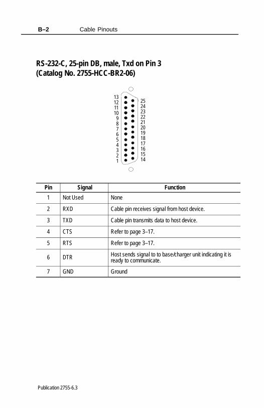
Cable PinoutsB–2
Publication 2755-6.3
RS-232-C, 25-pin DB, male, Txd on Pin 3 (Catalog No. 2755-HCC-BR2-06)
252423222120191817161514
13121110987654321
Pin Signal Function
1 Not Used None
2 RXD Cable pin receives signal from host device.
3 TXD Cable pin transmits data to host device.
4 CTS Refer to page 3–17.
5 RTS Refer to page 3–17.
6 DTR Host sends signal to to base/charger unit indicating it isready to communicate.
7 GND Ground

Cable Pinouts B–3
Publication 2755-6.3
RS-232-C, 25-pin DB, male, Txd on Pin 2 (Catalog No. 2755-HCC-BR1-06)
252423222120191817161514
13121110987654321
Pin Signal Function
1 Not Used None
2 TXD Cable pin transmits data to host device.
3 RXD Cable pin receives signal from host device.
4 RTS Refer to page 3–17.
5 CTS Refer to page 3–17.
6 Not Used None
7 GND Ground
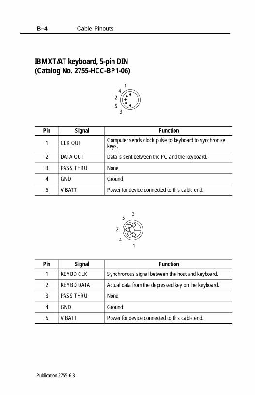
Cable PinoutsB–4
Publication 2755-6.3
IBM XT/AT keyboard, 5-pin DIN(Catalog No. 2755-HCC-BP1-06)
4
53
2
1
Pin Signal Function
1 CLK OUT Computer sends clock pulse to keyboard to synchronizekeys.
2 DATA OUT Data is sent between the PC and the keyboard.
3 PASS THRU None
4 GND Ground
5 V BATT Power for device connected to this cable end.
4
53
2
1
Pin Signal Function
1 KEYBD CLK Synchronous signal between the host and keyboard.
2 KEYBD DATA Actual data from the depressed key on the keyboard.
3 PASS THRU None
4 GND Ground
5 V BATT Power for device connected to this cable end.

Cable Pinouts B–5
Publication 2755-6.3
PS/2 keyboard. 6-pin Mini-DIN(Catalog No. 2755-HCC-BP2-06)
4
6 5
3
2 1
Pin Signal Function
1 KEYBD DATA Actual data from the depressed key on the keyboard.
2 Not Used None
3 GND Ground
4 V BATT Power for device connected to this cable end.
5 KEYBD CLK Synchronous signal between the host and keyboard.
6 Not Used None
4
6 5
3
2 1
Pin Signal Function
1 DATA OUT Data is sent between the PC and the keyboard.
2 Not Used None
3 GND Ground
4 V BATT Power for device connected to this cable end.
5 CLK OUT Computer sends clock pulse to keyboard to synchronizekeys.
6 Not Used None
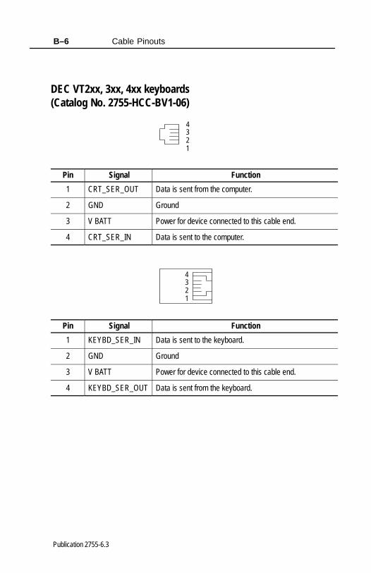
Cable PinoutsB–6
Publication 2755-6.3
DEC VT2xx, 3xx, 4xx keyboards(Catalog No. 2755-HCC-BV1-06)
4321
Pin Signal Function
1 CRT_SER_OUT Data is sent from the computer.
2 GND Ground
3 V BATT Power for device connected to this cable end.
4 CRT_SER_IN Data is sent to the computer.
4321
Pin Signal Function
1 KEYBD_SER_IN Data is sent to the keyboard.
2 GND Ground
3 V BATT Power for device connected to this cable end.
4 KEYBD_SER_OUT Data is sent from the keyboard.

������� �
Publication 2755-6.3
�������� ���� ��� ��� ��
This appendix describes how to use the Advanced Data Format(ADF) feature. Included are sections on:
• ADF overview
• rules hierarchy
• default rule
• listening for audible responses
• using ADF in a sorting application
ADF Overview
ADF allows you to customize input before it is transmitted to yourhost device. For example, instead of having a direct read of a barcode, you can now attach a message to it. ADF is implemented witha series of bar codes that have selectable parameters. [You do nothave to type in the individual characters for your message but ratherscan in the appropriate bar code located in the Hand-Held CordlessBar Code Scanners Programming Guide (Publication No. 2755-6.6).] This series of bar codes is called a Rule and is usedto evaluate input from the scanner. Rules are comprised of Criteriaand Actions. Criteria are composed of an Input Source, Code Type,and Code Length. Actions are composed of Send Data, SendKeystroke, Setup Pause, and Send Preset Value. Criteria, Actions,and entire Rules may be erased by scanning the appropriate bar code.
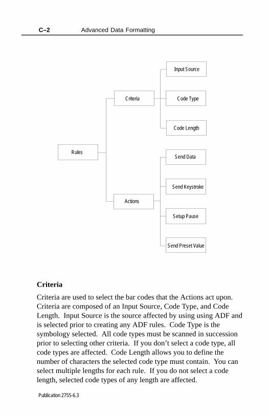
Advanced Data FormattingC–2
Publication 2755-6.3
Input Source
Rules
Criteria
Actions
Code Type
Code Length
Send Data
Send Keystroke
Setup Pause
Send Preset Value
Criteria
Criteria are used to select the bar codes that the Actions act upon.Criteria are composed of an Input Source, Code Type, and CodeLength. Input Source is the source affected by using using ADF andis selected prior to creating any ADF rules. Code Type is thesymbology selected. All code types must be scanned in successionprior to selecting other criteria. If you don’t select a code type, allcode types are affected. Code Length allows you to define thenumber of characters the selected code type must contain. You canselect multiple lengths for each rule. If you do not select a codelength, selected code types of any length are affected.

Advanced Data Formatting C–3
Publication 2755-6.3
Actions
Actions allow you to select how to format data for transmission.Actions are composed of Send Data, Send Keystroke, Setup Pause,and Send Preset Value. Send Data allows you to send all the datathat follows, send all the data up to a specific character selected fromthe alphanumeric keyboard bar code, or send the next number ofcharacters (1 to 254) selected from the alphanumeric keyboard.Send Keystroke allows you to scan the bar code for the keystrokeyou wish to send. Setup Pause allows you to set the pause durationparameter prior to entering ADF. Send Preset Value allows you tosend values 1 or 2 by scanning the appropriate bar code.
• value 1 = scan suffix
• value 2 = scan prefix
Rules Hierarchy
The last rule entered is the first rule read by the scanner. Thescanner reads the information and determines what needs to beaccomplished. If the last rule read is valid, the scanner may not goon to the other rules so positioning of the rules is very important.
Default Rule
The default rule is Send All Data. If all the rules you create do notmeet the criteria, all the data is sent.

Advanced Data FormattingC–4
Publication 2755-6.3
Listening for an ADF Audible Response
When scanning an ADF bar code symbol, you hear beeps from thescanner. Refer to the following tables to determine the meaning ofthe beeps.
Beep Indicating Normal Operation
The duration of the following tones are short.
This Response Indicates
2 Beeps (high–low tone) Entry of a number is expected. Enter anotherdigit. Add leading zeros to the front if needed.
2 Beeps (low–low tone)Entry of a alphabetic character is expected.Enter another alphabetic character or scanthe End of Message bar code.
2 Beeps (high–high tone)Entry of a Criteria or Action is expected.Enter another Criteria or Action or scan theSave Rule bar code.
4 Beeps (high–low–high–low tone) The Rule is saved. Rule entry mode is exited.
3 Beeps (high–low–low tone)All Criteria and Actions were cleared for theRule currently being entered. Continue entryof Rule.
1 Beep (low tone)Last saved Rule was successfully deleted.The Rule presently being entered isunchanged.
3 Beeps (low–low–high tone) All Rules are now deleted. The Rulepresently being entered is left alone.

Advanced Data Formatting C–5
Publication 2755-6.3
Beep Indicating Error
The duration of the following tones are long.
This Response Indicates
4 Beeps (low–high–low–high tone) Out of Rule memory. Erase some of theexisting Rules, then try and save Rule again.
3 Beeps (low–high–low tone)Cancel rule entry. Rule entry mode exitedbecause of an error or you were asked to exitRule entry.
2 Beeps (low–high tone)
The wrong bar code was scanned. Re–enterthe Criteria or Action. All previously enteredCriteria and Actions are retained. Criteria orAction list is too long for a Rule.
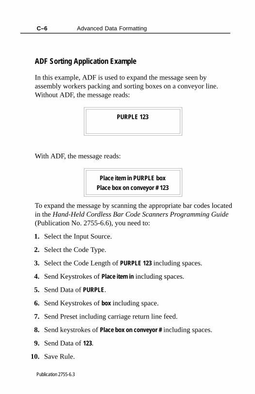
Advanced Data FormattingC–6
Publication 2755-6.3
ADF Sorting Application Example
In this example, ADF is used to expand the message seen byassembly workers packing and sorting boxes on a conveyor line.Without ADF, the message reads:
PURPLE 123
With ADF, the message reads:
Place item in PURPLE box
Place box on conveyor # 123
To expand the message by scanning the appropriate bar codes locatedin the Hand-Held Cordless Bar Code Scanners Programming Guide(Publication No. 2755-6.6), you need to:
1. Select the Input Source.
2. Select the Code Type.
3. Select the Code Length of PURPLE 123 including spaces.
4. Send Keystrokes of Place item in including spaces.
5. Send Data of PURPLE.
6. Send Keystrokes of box including space.
7. Send Preset including carriage return line feed.
8. Send keystrokes of Place box on conveyor # including spaces.
9. Send Data of 123.
10. Save Rule.
Glossary
Publication 2755-6.3
A
ASCIIAmerican Standard Code for Information Interchange. A7-bit-plus-parity code representing 128 letters, numerals,punctuation marks, and control characters. ASCII is a standarddata transmission code in the U.S.
B
BitBinary digit. One bit is the basic unit of binary information.Generally, eight consecutive bits compose one byte of data. Thepattern of 0 and 1 values within the byte determines its meaning.
ByteOn an addressable boundary, eight adjacent binary digits (0 and 1)combined in a pattern to represent a specific character or numericvalue. Bits are numbered from the right, 0 through 7, with bit 0 thelow-order bit. One byte in memory can be used to store one ASCIIcharacter.
C
CDRHCenter for Devices and Radiological Health. This is a federal agencyresponsible for regulating laser product safety. This agency specifiesvarious laser operation classes based on power output duringoperation.

G–2 Glossary
Publication 2755-6.3
Check DigitA digit used to verify a correct symbol decode. The scanner insertsthe decoded data into an arithmetic formula and checks that theresulting number matches the encoded check digit. Check digits arerequired for UPC but are optional for other symbologies. Usingcheck digits decreases the chance of substitution errors when an erroris decoded.
CodabarA discrete self-checking code with a character set consisting of digits0 to 9 and six additional characters: (- $ : / , +).
Code 128A high density symbology which allows the controller to encode all128 ASCII characters without adding extra symbol elements.
Code 3 of 9 (Code 39)A versatile and widely used alphanumeric bar code symbology witha set of 43 character types, including all uppercase letters, numeralsfrom 0 to 9, and 7 special characters (- . / + % $ and space). Thecode name is derived from the fact that 3 of 9 elements representinga character are wide, while the remaining 6 are narrow.
D
DecodeTo recognize a bar code symbology (e.g., UPC/EAN) and thenanalyze the content of the specific bar code scanned.
Discrete 2 of 5A binary bar code symbology representing each character by a groupof five bars, two of which are wide. The location of wide bars in thegroup determines which character is encoded; spaces areinsignificant. Only numeric characters (0 to 9) and start/stopcharacters may be encoded.
Glossary G–3
Publication 2755-6.3
E
EANEuropean Article Number. This European/International version ofthe UPC provides its own coding format and symbology standards.Element dimensions are specified metrically. EAN is used primarilyin retail.
H
Host ComputerA computer that serves other terminals in a network, providing suchservices as computation, database access, supervisory programs, andnetwork control.
I
Interleaved Bar CodeA bar code in which characters are paired together, using bars torepresents the first character and the intervening spaces to representthe second.
Interleaved 2 of 5A binary bar code symbology representing character pairs in groupsof five bars and five interleaved spaces. Interleaving provides forgreater information density. The location of wide elements(bar/spaces) within each group determines which characters areencoded. This continuous code type uses no intercharacter spaces.Only numeric (0 to 9) and start/stop characters may be encoded.
G–4 Glossary
Publication 2755-6.3
L
LaserAn acronym for Light Amplification by Stimulated Emission ofRadiation. The laser is an intense light source. Light from a laser isall the same frequency, unlike the output of an incandescent bulb.Laser light is typically coherent and has a high energy density.
Laser DiodeA gallium-arsenide semiconductor type of laser connected to a powersource to generate a laser beam. This laser type is a compact sourceof coherent light.
P
ParameterA variable that can have different values assigned to it.
S
ScannerAn electronic device used to scan bar code symbols and produce adigitized pattern that corresponds to the bars and spaces of thesymbol. Its three main components are:
• light source (laser or photoelectric cell) - illuminates a bar code.
• photodetector - registers the difference in reflected light (morelight reflected from spaces).
• signal conditioning circuit - transforms optical detector outputinto a digitized bar pattern.
SymbolA scannable unit that encodes data within the conventions of acertain symbology, usually including start/stop characters, quietzones, data characters, and check characters.

Glossary G–5
Publication 2755-6.3
SymbologyThe structural rules and conventions for representing data within aparticular bar code type (e.g. UPC/EAN, Code 39).
U
UPCUniversal Product Code. A relatively complex numeric symbology.Each character consists of two bars and two spaces, each of whichcan be one of four widths. This is the standard symbology forretail food packages in the United States.
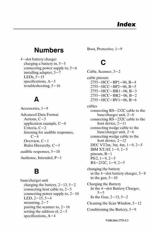
Publication 2755-6.3
�������
������ ����� � ��� ����� � ����� ��� ������������ ��� ������ ��� ������������� ������ �������� ������������������ ��������� ������� ����
�
��������� ��
��!���� ���� "�#���������� $������������� %�#��� $��$����� $�&�������� �� ������ �������
$��'!!��� $��(��� )��� �� $��
������ ������� ���*
������� +������ ,��
���-� �� ����� ����� � ������ &���� ��&��������� ��� ���� ��� &����������� ��� ������ ��� &��.���� &���� ���#�������� &�������� � ����� ��� &��������� � ����� ��� &���������������� ���
/���� ,�����!� ��
$���� 0����� ��&
���� �������&����)$$�/,��.�� /��&����)$$�/,&�.�� /��&����)$$�/(��.�� /��&����)$$�/(&�.�� /�&&����)$$�/1��.�� /��
�������������� (0�&�&$ ���� �� �
���-� �� ����� &����������� (0�&�&$ ���� �� �
��� �!��� &������������ ��� ���� �� �
���-� �� ����� &����������� ��� ���� �� �
��� �!��� &��&��$ 12&%%� �%%� �%%� �� � &��+/3 42-�2� �� � &���������� /��,0-&� �� � &��(0�&�&$� �� � &��
� ������ � ������� � ������ ����� � ��� ��*�� � ���� ���.
$ ����� � /����+� � ������ /���� $ ���
���+� � 5��� &���� ��&
$������ � 0��� 6������ ���&
$����������� � /����� ��
�����

IndexI–2
Publication 2755-6.3
���������� � ������!������ 0�#�������� ��&$����������� 07���� ��&&������ �������� ����#������ ���� ��� ���,��#� ����������� ��*,��#� 0�������� ���
��������� ��� ���� �� � ���-� ��
����� &�� ��� ���� �� � ��� �!���
&������ ������ �� � ���-� ��
���� ��� ��� �������&��.
$��������� �����/���� 5�����2� ����� 0!���� ���
$������ �� � �� 3������ ,�&
�
5����� 2� ����� 0!��� 85209����
�
+#������ :��� �� 0����0���#�� &�&
+����� ������� ,��
��������� ����� ��������� ��#���� ,��
���������� ����� � ��� ��*�
����� �������-� �� ����� &���� �������� ���� ��&� ���
�
#���������� � ������ ���&
3�;� 0���� "����� ��&
#����������-� �� ����� &����� ������� &�
�
������� � ������ ���
�
������ � ����� �� � ���-� �� ����� &���
,��#� ����������� ��*
,��#� 0�������� ���
��� ������#�������� &� �������������� ���
,�����! /���� ��
������������ ����� ,��
�
(�� (����� ���
(���� ,������������ ,��
Index I–3
Publication 2755-6.3
(0�&�& +����� $���� ��
�
0���� +���#������ ���
0���� � (�� (����� ���
��������������� �� ������ �� $������ � 0��� 6������ ���&����������� ��������� �������� �������� ��� ��&�#������ ���� �� �����������
&�&� �������� ���#���������� � ���� �������
���&�������� ��������� �� � ���-� �� �����
&�������� ����#������ ���0������� /� $���� ��&�������� ����� ����������������� ��������� ��� ������ ��������� ������� ����
0������� /� $���� ��&
0������� (����� ���
0����� � ����� �� � /��-� �� <���� &��
������������������� ����� � ��� ������-� �� ����� ������ ������� ���������� ���
������� 520� ���
��#�������� ���
�
�� ����� ������� ���
2����� =�� 0����� ���
������ ������������ ����� � ��� ����������� ����
�
<����>��� � �7���#��� &�&
�
��������� ��� �� ,������� ����� ���
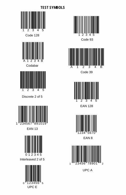
1 2 3 4 5
Code 128 1 2 3 4 5
Code 93
A 1 2 3 4 B
Codabar A 1 2 3 4 B
Code 39
1 2 3 4 5
Discrete 2 of 51 2 3 4 5
EAN 128
1 234567 891019
EAN 13 1234 5670
EAN 8
0 1 2 3 4 5
Interleaved 2 of 51 23456 78901 2
UPC A
0 123456 5
UPC E
TEST SYMBOLS

Packing Data
PK
Worldwide representation.
Argentina • Australia • Austria • Bahrain • Belgium • Brazil • Bulgaria • Canada • Chile • China, PRC •Colombia • Costa Rica • Croatia • Cyprus • Czech Republic • Denmark • Ecuador • Egypt • El Salvador •Finland • France • Germany • Greece • Guatemala • Honduras • Hong Kong • Hungary • Iceland • India •Indonesia • Ireland • Israel • Italy • Jamaica • Japan • Jordan • Korea • Kuwait • Lebanon • Malaysia •Mexico • Netherlands • New Zealand • Norway • Pakistan • Peru • Philippines • Poland • Portugal •Puerto Rico • Qatar • Romania • Russia–CIS • Saudi Arabia • Singapore • Slovakia • Slovenia • SouthAfrica, Republic • Spain • Sweden • Switzerland • Taiwan • Thailand • Turkey • United Arab Emirates •United Kingdom • United States • Uruguay • Venezuela • Yugoslavia
Allen-Bradley Headquarters, 1201 South Second Street, Milwaukee, WI 53204 USA, Tel: (1)414 382-2000 Fax: (1) 414 382-4444
Publication 2755-6.3 – January 1998Supersedes Publication 2755-6.3 – October 1996
PN 40062-330-01(B)Copyright 1998 Allen-Bradley Company, Inc. Printed in USA