27157040-Service-Guide-Peugeot-306-GTI-6-1997-1998
43
Service Guide Peugeot 306 GTI-6 1997-1998
-
Upload
love-vapor -
Category
Documents
-
view
37 -
download
0
description
fixing a peaugeot car
Transcript of 27157040-Service-Guide-Peugeot-306-GTI-6-1997-1998

Service Guide
Peugeot 306 GTI-6
1997-1998

Carried out by
9000 miles Customer NameVehicle Registration
Current Mileage:
Service at
Peugeot 306 2.0i GTI-6 16 valve 1997-1998Engine Code: XU10J4(RFS)
Carried out on __________________
The items checked on this inspection are shown below. Where inspection has indicated the need for further attention in the interests of safety and maintenance of your vehicle value, we recommend that corrective action is taken as soon as possible.
XRequires further attention
OK
Service Details:
Engine oil: changeOil filter: replaceAutomatic transmission: drain & refill**** for the above see Special Notes (1) ****Automatic transmission: check fluid levelTransfer box: check oil levelDifferential for (4WD): check oil level**** for the above see Special Notes (2) ****Vehicle underside: complete checkEngine: check for leaks & damageP.A.S. system: check for leaksHydraulic system: replace filterLights / indicators / controls / warning lamps: checkClutch: pedal height check / adjustBattery: check for leaks / charge level / distilled water top-upWindscreen wiper / wash: check fluid level / antifreeze contentCooling system: check for level / specific gravityBrake fluid level: checkP.A.S. fluid level: checkCooling system: check for level / specific gravityCheck on rolling road or test drive
Page 1 of 1
I confirm that all the appropriate checks and adjustments have been made correctly.
Technician: .................................................................................. Workshop Supervisor: ...............................................................................

Carried out by
18000 miles Customer NameVehicle Registration
Current Mileage:
Service at
Peugeot 306 2.0i GTI-6 16 valve 1997-1998Engine Code: XU10J4(RFS)
Carried out on __________________
The items checked on this inspection are shown below. Where inspection has indicated the need for further attention in the interests of safety and maintenance of your vehicle value, we recommend that corrective action is taken as soon as possible.
XRequires further attention
OK
Service Details:
Engine oil: changeOil filter: replaceAutomatic transmission: drain & refill**** for the above see Special Notes (1) ****Transfer box: refillDifferential for (4WD): refill**** for the above see Special Notes (2) ****Automatic transmission: check fluid levelDrive shaft boots: check / replaceBall joints: check for wearVehicle underside: complete checkEngine: check for leaks & damageP.A.S. system: check for leaksClutch: pedal height check / adjustParking brake: check / adjustBrake pads front: clean / check / replaceSpark plugs: replace / adjustV-belt(s): check / adjust / replacePollen filter: replaceBattery: check for leaks / charge level / distilled water top-upWindscreen wiper / wash: check fluid level / antifreeze contentCooling system: check for level / specific gravityBrake fluid level: checkP.A.S. fluid level: checkFuel filter(s): check / replaceLights / indicators / controls / warning lamps: checkCruise control system: checkTyres including spare: check condition / pressure / tread depthCheck on rolling road or test drive**** for the above see Special Notes (3) ****
Page 1 of 1
I confirm that all the appropriate checks and adjustments have been made correctly.
Technician: .................................................................................. Workshop Supervisor: ...............................................................................

Carried out by
27000 miles Customer NameVehicle Registration
Current Mileage:
Service at
Peugeot 306 2.0i GTI-6 16 valve 1997-1998Engine Code: XU10J4(RFS)
Carried out on __________________
The items checked on this inspection are shown below. Where inspection has indicated the need for further attention in the interests of safety and maintenance of your vehicle value, we recommend that corrective action is taken as soon as possible.
XRequires further attention
OK
Service Details:
Oil filter: replaceAutomatic transmission: drain & refillTransfer box: check oil levelDifferential for (4WD): check oil level**** for the above see Special Notes (2) ****P.A.S. fluid level: checkCooling system: check for level / specific gravityWindscreen wiper / wash: check fluid level / antifreeze contentBattery: check for leaks / charge level / distilled water top-upAir filter(s): replace elementPollen filter: replaceHydraulic system: check filter clean / replaceV-belt(s): check / adjust / replaceBrake pads front: clean / check / replaceBrake pads rear: clean / check / replaceDrive shaft boots: check / replaceBall joints: check for wearVehicle underside: complete checkTie rod ends: check for wear: check boots for damageEngine: check for leaks & damageP.A.S. system: check for leaksShock absorbers: check for leaks / wear / damage etc.Tyres including spare: check condition / pressure / tread depthClutch: pedal height check / adjustParking brake: check / adjustLights / indicators / controls / warning lamps: checkEngine management: self diagnostics checkCruise control system: checkBrake fluid: replaceCheck on rolling road or test drive
Page 1 of 1
I confirm that all the appropriate checks and adjustments have been made correctly.
Technician: .................................................................................. Workshop Supervisor: ...............................................................................

Carried out by
36000 miles Customer NameVehicle Registration
Current Mileage:
Service at
Peugeot 306 2.0i GTI-6 16 valve 1997-1998Engine Code: XU10J4(RFS)
Carried out on __________________
The items checked on this inspection are shown below. Where inspection has indicated the need for further attention in the interests of safety and maintenance of your vehicle value, we recommend that corrective action is taken as soon as possible.
XRequires further attention
OK
Service Details:
Engine oil: changeOil filter: replaceAutomatic transmission: drain & refill**** for the above see Special Notes (1) ****Transfer box: refillDifferential for (4WD): refill**** for the above see Special Notes (2) ****Differential for (4WD): refillAutomatic transmission: check fluid levelDrive shaft boots: check / replaceBall joints: check for wearVehicle underside: complete checkEngine: check for leaks & damageP.A.S. system: check for leaksClutch: pedal height check / adjustParking brake: check / adjustBrake pads front: clean / check / replaceLinings rear: clean / check / replaceSpark plugs: replace / adjustV-belt(s): check / adjust / replacePollen filter: replaceBattery: check for leaks / charge level / distilled water top-upWindscreen wiper / wash: check fluid level / antifreeze contentCooling system: check for level / specific gravityBrake fluid level: checkP.A.S. fluid level: checkFuel filter(s): check / replaceLights / indicators / controls / warning lamps: checkCruise control system: checkTyres including spare: check condition / pressure / tread depthCheck on rolling road or test drive**** for the above see Special Notes (3) ****
Page 1 of 1
I confirm that all the appropriate checks and adjustments have been made correctly.
Technician: .................................................................................. Workshop Supervisor: ...............................................................................

Carried out by
45000 miles Customer NameVehicle Registration
Current Mileage:
Service at
Peugeot 306 2.0i GTI-6 16 valve 1997-1998Engine Code: XU10J4(RFS)
Carried out on __________________
The items checked on this inspection are shown below. Where inspection has indicated the need for further attention in the interests of safety and maintenance of your vehicle value, we recommend that corrective action is taken as soon as possible.
XRequires further attention
OK
Service Details:
Engine oil: changeOil filter: replaceAutomatic transmission: drain & refill**** for the above see Special Notes (1) ****Automatic transmission: check fluid levelTransfer box: check oil levelDifferential for (4WD): check oil level**** for the above see Special Notes (2) ****Vehicle underside: complete checkEngine: check for leaks & damageFuel filter(s): replaceP.A.S. system: check for leaksHydraulic system: replace filterLights / indicators / controls / warning lamps: checkClutch: pedal height check / adjustBattery: check for leaks / charge level / distilled water top-upWindscreen wiper / wash: check fluid level / antifreeze contentCooling system: check for level / specific gravityBrake fluid level: checkP.A.S. fluid level: checkCooling system: check for level / specific gravityCheck on rolling road or test drive
Page 1 of 1
I confirm that all the appropriate checks and adjustments have been made correctly.
Technician: .................................................................................. Workshop Supervisor: ...............................................................................

Carried out by
54000 miles Customer NameVehicle Registration
Current Mileage:
Service at
Peugeot 306 2.0i GTI-6 16 valve 1997-1998Engine Code: XU10J4(RFS)
Carried out on __________________
The items checked on this inspection are shown below. Where inspection has indicated the need for further attention in the interests of safety and maintenance of your vehicle value, we recommend that corrective action is taken as soon as possible.
XRequires further attention
OK
Service Details:
Engine oil: changeOil filter: replaceAutomatic transmission: drain & refillTransfer box: refillDifferential for (4WD): refill**** for the above see Special Notes (2) ****Gearbox / differential: check oil levelClutch: pedal height check / adjustParking brake: check / adjustBrake pads front: clean / check / replaceBrake pads rear: clean / check / replaceLinings rear: clean / check / replaceDrive shaft boots: check / replaceBall joints: check for wearVehicle underside: complete checkHydraulic system: check filter clean / replaceEngine: check for leaks & damageP.A.S. system: check for leaksShock absorbers: check for leaks / wear / damage etc.Hydraulic system: replace fluidBrake fluid: replaceCooling system: drain / flush / refill**** for the above see Special Notes (3) ****P.A.S. fluid level: checkCooling system: check for level / specific gravityWindscreen wiper / wash: check fluid level / antifreeze contentBattery: check for leaks / charge level / distilled water top-upAir filter(s): replace elementPollen filter: replaceV-belt(s): check / adjust / replaceSpark plugs: replace / adjustLights / indicators / controls / warning lamps: checkEngine management: self diagnostics checkCheck on rolling road or test drive
Page 1 of 1
I confirm that all the appropriate checks and adjustments have been made correctly.
Technician: .................................................................................. Workshop Supervisor: ...............................................................................

Carried out by
72000 miles Customer NameVehicle Registration
Current Mileage:
Service at
Peugeot 306 2.0i GTI-6 16 valve 1997-1998Engine Code: XU10J4(RFS)
Carried out on __________________
The items checked on this inspection are shown below. Where inspection has indicated the need for further attention in the interests of safety and maintenance of your vehicle value, we recommend that corrective action is taken as soon as possible.
XRequires further attention
OK
Service Details:
Engine oil: changeOil filter: replaceAutomatic transmission: drain & refillTransfer box: refillDifferential for (4WD): refill**** for the above see Special Notes (2) ****Gearbox / differential: check oil levelClutch: pedal height check / adjustParking brake: check / adjustBrake pads front: clean / check / replaceBrake pads rear: clean / check / replaceLinings rear: clean / check / replaceDrive shaft boots: check / replaceBall joints: check for wearVehicle underside: complete checkHydraulic system: check filter clean / replaceEngine: check for leaks & damageP.A.S. system: check for leaksShock absorbers: check for leaks / wear / damage etc.Brake fluid: replaceCooling system: drain / flush / refill**** for the above see Special Notes (3) ****P.A.S. fluid level: checkCooling system: check for level / specific gravityWindscreen wiper / wash: check fluid level / antifreeze contentBattery: check for leaks / charge level / distilled water top-upAir filter(s): replace elementPollen filter: replaceV-belt(s): check / adjust / replace**** for the above see Special Notes (4) ****Timing belt(s): replaceSpark plugs: replace / adjustLights / indicators / controls / warning lamps: checkEngine management: self diagnostics checkCheck on rolling road or test drive
Page 1 of 1
I confirm that all the appropriate checks and adjustments have been made correctly.
Technician: .................................................................................. Workshop Supervisor: ...............................................................................

Carried out by
90000 miles Customer NameVehicle Registration
Current Mileage:
Service at
Peugeot 306 2.0i GTI-6 16 valve 1997-1998Engine Code: XU10J4(RFS)
Carried out on __________________
The items checked on this inspection are shown below. Where inspection has indicated the need for further attention in the interests of safety and maintenance of your vehicle value, we recommend that corrective action is taken as soon as possible.
XRequires further attention
OK
Service Details:
Engine oil: changeOil filter: replaceAutomatic transmission: drain & refill**** for the above see Special Notes (1) ****Transfer box: refillDifferential for (4WD): refill**** for the above see Special Notes (2) ****Automatic transmission: check fluid levelDrive shaft boots: check / replaceBall joints: check for wearVehicle underside: complete checkEngine: check for leaks & damageFuel filter(s): replaceP.A.S. system: check for leaksClutch: pedal height check / adjustParking brake: check / adjustBrake pads front: clean / check / replaceSpark plugs: replace / adjustV-belt(s): check / adjust / replacePollen filter: replaceHydraulic system: replace filterBattery: check for leaks / charge level / distilled water top-upWindscreen wiper / wash: check fluid level / antifreeze contentCooling system: check for level / specific gravityBrake fluid level: checkP.A.S. fluid level: checkFuel filter(s): check / replaceLights / indicators / controls / warning lamps: checkCruise control system: checkTyres including spare: check condition / pressure / tread depthCheck on rolling road or test drive**** for the above see Special Notes (3) ****
Page 1 of 1
I confirm that all the appropriate checks and adjustments have been made correctly.
Technician: .................................................................................. Workshop Supervisor: ...............................................................................

Peugeot 306 2.0i GTI-6 16 valve 1997-1998Engine Code: XU10J4(RFS)
Special Notes
1. 405/605 models only2. 405 4 x 4 only3. . coolant - change every 2 years4. only TU & X U engines
Page 1 of 1

Changing gearbox oil. I found that the best way to drain the oil is without taking the wheels off, this stop the oil from cooling down. It’s difficult enough to get the oil when it’s hot, nearly impossible when cold. It’s fairly easy to do without removing the wheel and then it’s easier to raise the driver side to drain the oil. Also, make sure you have: -a length of tubing 8mm approx. diameter -some PTFE thread seal tape to seal where the tube goes into the gearbox - a funnel to attach to the tube -2.15 litres of oil -three washers, I can’t remember the diameters, sorry. Get a bag of different sizes perhaps? I took the bolts out and then drove to the shop in my other car. So, here is my attempt to guide through changing the oil as simple as possible:
1) Take the car for a long, fast drive to warm the gearbox oil. You need it to be warm so that it drains well.
2) Put a full left lock on so that you can get to the gearbox. Jack the car up from
the front passenger side. Place something under the gearbox to catch oil and undo the drain plug, circled in green. The gearbox is on the passenger side of the car. The oil comes out of this bolt fast so be careful.

3) Then undo the filler plug circled in red and the other bolt circled in blue so
that the oil can flow out better. I find it better to undo the bolts this way so that you don’t get oil coming out too fast and possibly scalding you.

4) When the oil starts to slow down, jack up the driver side high to tip more of
the oil out. 5) I left the car with the driver jacked up for about 1 hour to get as much of the
oil out as possible. 6) Then the tricky part, first lower the driver side and make sure the car is level. 7) Then fit a new washer and refit the drain plug and the bolt circled in blue. 8) Then wrap PTFE tape around one end of the tube and drop it into the funnel so
that the PTFE end falls in last and forms a seal. I’m trying to describe this as best I can!
9) Then insert the tube into the filler hole, bend the tube so that the funnel is upright without kinking the tube and perhaps attach the funnel to the suspension spring to make it easier if you like.
10) Pour oil very slowly into the gearbox so that it disperses well. This can take a lot of time!
11) Keep topping up until some oil flows out, then take the tube out and let the excess drain out. Refit the filler plug with a new washer.
12) Take it for a drive and then check the drain plug by pouring a bit more oil in and letting it drain off. You can’t overfill the gearbox as long as you let the excess drain off and make sure the car is level.
Also, the gearbox oil absolutely stinks!!! Seriously, it is rancid.

Adjustment Data (Brakes)
Peugeot 306 2.0i GTI-6 16 valve 1997-1998Engine Code: XU10J4(RFS)
DESCRIPTION SETTING UNIT
Type: Front / Rear disc / discFront Disc Thickness: New / Limit 20.40/18.40 mmRear Disc Thickness: New / Limit 8/6 mmRear Drum Diameter: New / Limit N/AFront Pad Limit 2 mmRear Pad Limit 2 mmRear Lining Limit N/AParking Brake Travel 4/7 notches
Page 1 of 1

Adjustment Data (Electrical)
Peugeot 306 2.0i GTI-6 16 valve 1997-1998Engine Code: XU10J4(RFS)
DESCRIPTION SETTING UNIT
Battery Capacity 12/- v/AhAlternator Power 75 AControlled Voltage 13.80/14.80 VStarter Motor Power 1.1 kW
Page 1 of 1

Adjustment Data (Engine)
Peugeot 306 2.0i GTI-6 16 valve 1997-1998Engine Code: XU10J4(RFS)
DESCRIPTION SETTING UNIT
Engine Code XU10J4(RFY/RFS)Engine Format 4/DOHCCylinder Capacity 1998 ccValve Clearance Inlet hydraulicValve Clearance Exhaust hydraulicAdjustment Conditions N/A
Page 1 of 1

Adjustment Data (Fuel)
Peugeot 306 2.0i GTI-6 16 valve 1997-1998Engine Code: XU10J4(RFS)
DESCRIPTION SETTING UNIT
Carburettor / Injection Make Bosch/Magneti MarelliCarburettor / Injection Type Motronic MP 3.2 Mpi / Magneti Marelli 1APFuel Pump Pressure 3.00±0.20 barInjection Pressure 2.50±0.20 barIdle Speed non-adjustableRaised Idle Speed N/ACO At Idle Speed 0.50 maximum %Carbon Dioxide At Idle Speed 10 minimum %HC At Idle Speed 100 maximum ppmOxygen At Idle Speed 0.30±0.20 %
Page 1 of 1

Adjustment Data (Ignition)
Peugeot 306 2.0i GTI-6 16 valve 1997-1998Engine Code: XU10J4(RFS)
DESCRIPTION SETTING UNIT
System Type electronicSequence 1-3-4-2Contact Breaker Gap N/ASpark Plug Electrode Gap 0.8 mmTorque Setting 28 NmCoil Make Sagem / ValeoCoil Type BAE01Primary Resistance 0.7 OhmsSecondary Resistance 6600 OhmsStroboscopic Timing BTDC non-adjustableCentrifugal Advance Begins ECU controlledCentrifugal Advance Test ECU controlledCentrifugal Advance Ends ECU controlledVacuum Advance Begin electronic advanceVacuum Advance Test electronic advanceVacuum Advance Ends electronic advance
Page 1 of 1

Adjustment Data (Suspension)
Peugeot 306 2.0i GTI-6 16 valve 1997-1998Engine Code: XU10J4(RFS)
DESCRIPTION SETTING UNIT
Vehicle Loading kerbside weightFront Wheel Alignment toe inFront Wheel Tracking 2±1 mmFront Wheel Camber -0°20'±30' (RFS -25´±30´) deg.Front Wheel Castor 3°20'±30' (RFS 3°30´±30´) deg.Front Wheel KPI 11°±30' (RFS 11°15´±30´) deg.Rear Wheel Alignment toe inRear Wheel Tracking 4.20±1.50 (RFS 2.10±0.50) mmRear Wheel Camber -1°20'±15' deg.Tyre Size 195/55 VR 15Tyre Size N/ATyre Pressures Front 2 barTyre Pressures Rear 2.1 bar
Page 1 of 1

Adjustment Data (Torque Settings)
Peugeot 306 2.0i GTI-6 16 valve 1997-1998Engine Code: XU10J4(RFS)
DESCRIPTION SETTING UNIT
Cylinder Head Bolts Stage 1 35 NmCylinder Head Bolts Stage 2 70 NmCylinder Head Bolts Stage 3 160 deg.Cylinder Head Bolts Stage 4 N/ACylinder Head Bolts Stage 5 N/ABig End Nuts / Bolts 20.00 then 70 Nm / deg.Main Bearing Nuts / Bolts 80 NmFlywheel Nuts / Bolts 50 NmClutch to Flywheel Nuts / Bolts 25 NmInlet Manifold Nuts / Bolts 20 NmExhaust Manifold Nuts / Bolts 35 NmFront Hub Nut M20 265.00 M24 325.00 NmRear Hub Nut 185 NmRoad Wheel Nuts / Bolts 90 Nm
Page 1 of 1

Peugeot 306 2.0i GTI-6 16 valve 1997-1998Engine Code: XU10J4(RFS)
Circuit Diagram
Page 1 of 1
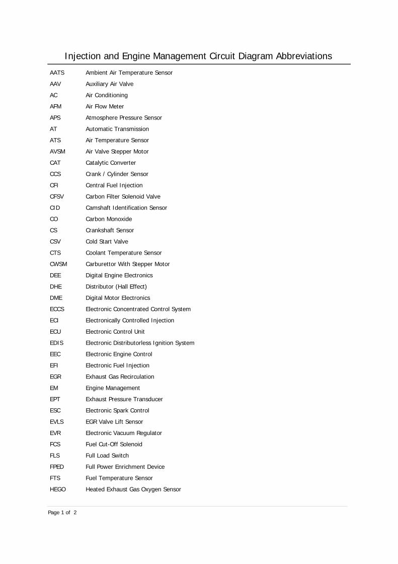
Injection and Engine Management Circuit Diagram Abbreviations
AATS Ambient Air Temperature Sensor
AAV Auxiliary Air Valve
AC Air Conditioning
AFM Air Flow Meter
APS Atmosphere Pressure Sensor
AT Automatic Transmission
ATS Air Temperature Sensor
AVSM Air Valve Stepper Motor
CAT Catalytic Converter
CCS Crank / Cylinder Sensor
CFI Central Fuel Injection
CFSV Carbon Filter Solenoid Valve
CID Camshaft Identification Sensor
CO Carbon Monoxide
CS Crankshaft Sensor
CSV Cold Start Valve
CTS Coolant Temperature Sensor
CWSM Carburettor With Stepper Motor
DEE Digital Engine Electronics
DHE Distributor (Hall Effect)
DME Digital Motor Electronics
ECCS Electronic Concentrated Control System
ECI Electronically Controlled Injection
ECU Electronic Control Unit
EDIS Electronic Distributorless Ignition System
EEC Electronic Engine Control
EFI Electronic Fuel Injection
EGR Exhaust Gas Recirculation
EM Engine Management
EPT Exhaust Pressure Transducer
ESC Electronic Spark Control
EVLS EGR Valve Lift Sensor
EVR Electronic Vacuum Regulator
FCS Fuel Cut-Off Solenoid
FLS Full Load Switch
FPED Full Power Enrichment Device
FTS Fuel Temperature Sensor
HEGO Heated Exhaust Gas Oxygen Sensor
Page 1 of 2

Injection and Engine Management Circuit Diagram Abbreviations
ICE Idle Control ECU
IDS Idle Switch
IGA Ignition Amplifier
IGC Ignition Coil
IMA Idle Mixture Adjuster
INR Injector Resistor
IRP Injector Resistor Pack
ISCV Idle Speed Control Valve
ISW Inertia Switch
KAM Keep Alive Memory
KS Knock Sensor
LS Lambda Sensor
MAP Manifold Absolute Pressure
MEMS Modular Engine Management System
MMFD Magneti Marelli Fuel Division
MPI Multi-Point Injection
OTS Oil Temperature Sensor
PA Power Amplifier
PGMFI Programmed Fuel Injection
PHS Phase Sensor
PIE Programmed Ignition ECU
PTC Positive Temperature Coefficient
RON Research Octane Number
RPM Revolutions Per Minute
RTS RPM / TDC Sensor
SPI Single Point Injection
TCCS Toyota Computer Control System
TDC Top Dead Centre
TFI Thick Film Ignition
TPS Throttle Position Sensor / Switch
TPSW Throttle Pedal Switch
TTS Thermo-Time Switch
UESC Universal Electronic Spark Control
UPAC Universal ESC Computer Plus ATS
VAS Vacuum Sensor
VSW Vacuum Switch
WR Warm-Up Regulator
Page 2 of 2

Injection and Engine M anagement Diagnostics - Generic Procedures
Peugeot 306 2.0i GTI-6 16 valve 1997-1998Engine Code: XU10J4(RFS)
Basic guidelines for diagnosing faults on vehicle systems (Generic text for information purposes only)
Diagnostic Process:
Six-stage process:Verify the fault.Collect further information.Evaluate the evidence.Carry out further tests in a logical sequence.Rectify the problem.Check all systems.
The art of diagnostics:The knowledge needed for accurate diagnostics is in two parts:Understanding of the system in which the problem exists.The ability to apply a logical diagnostic routine.
Diagnostics:What is an acceptable value?The reference data gives the resistance of a component between 60 ohms and 90 ohms.What if, when measured, the value is 55 ohms? If the measured value was 0 ohms or 1000 ohms then the component is faulty! In this case (55 ohms) it is very likely that the component is serviceable.The decision over this type of issue is difficult and must in many cases be based on experience. As a general guide the reading is in the right ‘order of magnitude’. The component has a good chance of being serviceable.This illustrates that diagnostic work can involve ‘playing the best odds’. As long as this is within a logical process.
Diagnostic Techniques:Check the obvious first!Start hands-on diagnostic routines with ‘hand and eye checks’. Look over the vehicle for obvious faults. For example, if automatic transmission fluid is leaking correct this before carrying out stall tests. Start on diagnostic routines with ‘hand and eye checks’. Look over the vehicle for obvious faults. For example, if the battery terminals are loose or corroded correct this before carrying out voltage readings. A misfire may be caused by a loose plug lead.It is easier to look for this than interpret the ignition waveforms.
Generic electrical testing procedure:The following procedure is very general but with adaptation can be applied to any electrical system. Refer to manufacturer’s recommendations if in any doubt. The process of checking any system circuit is broadly as follows:Checks (loose wires, switches and other obvious faults).Check battery - must be 70% charged.Check motor/solenoid/linkage/bulbs/unit.Fuse continuity - check voltage both sides with meter or test lamp.If used does the relay click?This means it has operated. It is not necessarily making contact.Supply to switch - battery voltage.Supply from the switch - battery voltage.Supplies to relay - battery voltage.Feed out of the relay - battery voltage.Voltage supply to the ‘motor’ (etc.) - within 0.5V of the battery.Earth circuit (continuity or voltage) - 0 ohms or 0V.
Test procedure:
Page 1 of 3

Injection and Engine Management Diagnostics - Generic Procedures
Peugeot 306 2.0i GTI-6 16 valve 1997-1998Engine Code: XU10J4(RFS)
Volt drop testing:Battery voltage normally about 12.6V with a drop that may be 0.1 or 0.2V.Voltage drop testing has a basic rule for a series electrical circuit. The sum of all volt drops around a circuit always adds up to the supply.Check that the circuit is switched on and operating, or trying to operate.When testing the battery voltage the measurement is say 12V.To further narrow the cause of a voltage drop, simply measure across a smaller area.
Testing for short circuits to earth:This fault will normally blow a fuse or burn out the wiring completely. Traceing a short circuit is very different to looking for a high resistance connection or an open circuit. The volt drop testing above will trace an open circuit or a high resistance connection.The method of tracing a short is to connect a bulb or test lamp across the blown fuse and switch on the circuit. The bulb will light because it is connected to the supply for the fuse and to earth via the fault.Now disconnect small sections of the circuit one at a time until the test lamp goes out. This will indicate the particular circuit section that has shorted out.
On and off load tests:On load means that a circuit is drawing a current. Off load means it is not.One example where this may be an issue is when testing a starter circuit. Battery voltage may be 12V off load but only 9V when on load.A second example is the supply to the + terminal of the coil via a high resistance connection (corroded switch terminal for example). With the ignition on and the vehicle not running, the reading will normally be battery voltage. The ignition ECU switches off the primary circuit and no volt drop will show up. If the circuit were switched on (with a fused jumper lead) a lower reading would result showing up the fault.
Black box technique:The technique that will be covered here is known as ‘black box fault finding’. It can be applied to many vehicle systems from engine management, ABS, cruise control and instrumentation.As most systems now revolve around an ECU it is considered to be a ‘black box’.Treating the ECU as a ‘black box’ allows us to ignore its complexity. If all sensors, output actuators, supply / earth connections and wiring is serviceable, the fault must be the ECU. Most ECU's are very reliable and it is far more likely that the fault will be found in the inputs or outputs.Normal fault finding or testing techniques can be applied to the sensors and actuators. Sometimes however, it is almost an advantage not to know the manufacturer's recommended readings. If the value should be between 800 ohms and 900 ohms, and the reading is 905 ohms the component is probably OK.No matter how complex the electronics in an ECU, they will not work without a good power supply and earth.
Sensor to ECU method:This technique is simple but very useful. A resistance test being carried out on a component is a direct measure of its resistance. The same test on the end of the component’s wires at the ECU includes the condition of the circuit. If the second reading is the same as the first then the circuit must be in good order.Note: The circuit supply must always be off when carrying out ohmmeter tests.
Back probing connectors:When testing for a supply (for example) at an ECU, use the probes of the digital meter with care. Connect to the back of the terminals to avoid damage to the connecting surfaces. A pin clamped to the test lead is ideal for connecting ‘through’ the insulation of a wire without disconnecting it.
Fault codes:Most management systems carry out self-diagnostic checks on sensors / actuators connected to the ECU(s). A fault in one of the components or its associated circuit causes a code to be stored in the ECU memory.The codes may be described as "fast" or "slow". Some ECU's produce both types. An LED, dash warning light, scope or even an analogue voltmeter can be used to read slow codes. Normally, slow codes are output as a series of flashes interpreted by checking with a fault code table. Slow codes are normally initiated by shorting two connections on the diagnostic plug.Then switching on the ignition.
Page 2 of 3

Injection and Engine Management Diagnostics - Generic Procedures
Peugeot 306 2.0i GTI-6 16 valve 1997-1998Engine Code: XU10J4(RFS)
Refer to detailed data before shorting any pins out.Fast codes can only be read by using a fault code reader or scanner. All future ECU's will use fast codes. If a code reader is attached to the serial port on the harness, fast and slow codes can be read from the ECU. These are displayed in the form of two, three or four digit codes, or if software is used, in text format.
Engine management:Engine management is a general term that describes the control of engine operation. This ranges from carburettor for fuel, with contact breakers to control ignition, to complex ECU systems.The task of an engine management system is to control ignition / fuel, and to refine basic engine control. This is done by taking in information from sensors and controlling outputs with actuators.
Page 3 of 3
Injection and Engine Management Diagnostics - Generic Testing
Peugeot 306 2.0i GTI-6 16 valve 1997-1998Engine Code: XU10J4(RFS)
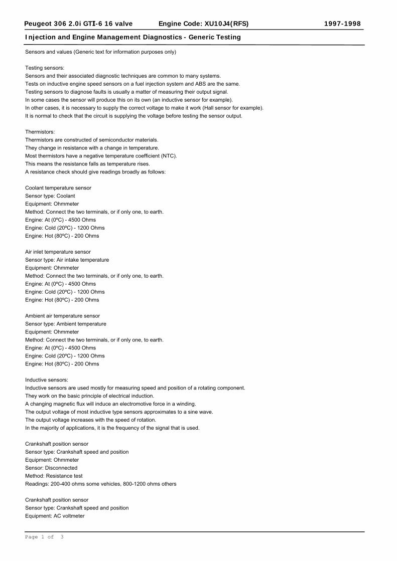
Sensors and values (Generic text for information purposes only)
Testing sensors:Sensors and their associated diagnostic techniques are common to many systems. Tests on inductive engine speed sensors on a fuel injection system and ABS are the same.Testing sensors to diagnose faults is usually a matter of measuring their output signal. In some cases the sensor will produce this on its own (an inductive sensor for example). In other cases, it is necessary to supply the correct voltage to make it work (Hall sensor for example).It is normal to check that the circuit is supplying the voltage before testing the sensor output.
Thermistors:Thermistors are constructed of semiconductor materials. They change in resistance with a change in temperature.Most thermistors have a negative temperature coefficient (NTC). This means the resistance falls as temperature rises. A resistance check should give readings broadly as follows:
Coolant temperature sensorSensor type: CoolantEquipment: OhmmeterMethod: Connect the two terminals, or if only one, to earth.Engine: At (0ºC) - 4500 OhmsEngine: Cold (20ºC) - 1200 OhmsEngine: Hot (80ºC) - 200 Ohms
Air inlet temperature sensorSensor type: Air intake temperatureEquipment: OhmmeterMethod: Connect the two terminals, or if only one, to earth.Engine: At (0ºC) - 4500 OhmsEngine: Cold (20ºC) - 1200 OhmsEngine: Hot (80ºC) - 200 Ohms
Ambient air temperature sensorSensor type: Ambient temperatureEquipment: OhmmeterMethod: Connect the two terminals, or if only one, to earth.Engine: At (0ºC) - 4500 OhmsEngine: Cold (20ºC) - 1200 OhmsEngine: Hot (80ºC) - 200 Ohms
Inductive sensors:Inductive sensors are used mostly for measuring speed and position of a rotating component. They work on the basic principle of electrical induction. A changing magnetic flux will induce an electromotive force in a winding.The output voltage of most inductive type sensors approximates to a sine wave. The output voltage increases with the speed of rotation. In the majority of applications, it is the frequency of the signal that is used.
Crankshaft position sensorSensor type: Crankshaft speed and positionEquipment: OhmmeterSensor: DisconnectedMethod: Resistance testReadings: 200-400 ohms some vehicles, 800-1200 ohms others
Crankshaft position sensorSensor type: Crankshaft speed and positionEquipment: AC voltmeter
Page 1 of 3
Injection and Engine Management Diagnostics - Generic Testing
Peugeot 306 2.0i GTI-6 16 valve 1997-1998Engine Code: XU10J4(RFS)
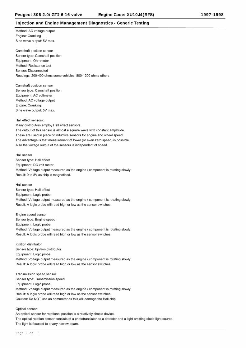
Method: AC voltage outputEngine: CrankingSine wave output: 5V max.
Camshaft position sensorSensor type: Camshaft positionEquipment: OhmmeterMethod: Resistance testSensor: DisconnectedReadings: 200-400 ohms some vehicles, 800-1200 ohms others
Camshaft position sensorSensor type: Camshaft positionEquipment: AC voltmeterMethod: AC voltage outputEngine: CrankingSine wave output: 5V max.
Hall effect sensors:Many distributors employ Hall effect sensors. The output of this sensor is almost a square wave with constant amplitude. These are used in place of inductive sensors for engine and wheel speed.The advantage is that measurement of lower (or even zero speed) is possible.Also the voltage output of the sensors is independent of speed.
Hall sensorSensor type: Hall effectEquipment: DC volt meterMethod: Voltage output measured as the engine / component is rotating slowly.Result: 0 to 8V as chip is magnetised.
Hall sensorSensor type: Hall effectEquipment: Logic probeMethod: Voltage output measured as the engine / component is rotating slowly.Result: A logic probe will read high or low as the sensor switches.
Engine speed sensorSensor type: Engine speedEquipment: Logic probeMethod: Voltage output measured as the engine / component is rotating slowly.Result: A logic probe will read high or low as the sensor switches.
Ignition distributorSensor type: Ignition distributorEquipment: Logic probeMethod: Voltage output measured as the engine / component is rotating slowly.Result: A logic probe will read high or low as the sensor switches.
Transmission speed sensorSensor type: Transmission speedEquipment: Logic probeMethod: Voltage output measured as the engine / component is rotating slowly.Result: A logic probe will read high or low as the sensor switches.Caution: Do NOT use an ohmmeter as this will damage the Hall chip.
Optical sensor:An optical sensor for rotational position is a relatively simple device. The optical rotation sensor consists of a phototransistor as a detector and a light emitting diode light source.The light is focused to a very narrow beam.
Page 2 of 3

Injection and Engine Management Diagnostics - Generic Testing
Peugeot 306 2.0i GTI-6 16 valve 1997-1998Engine Code: XU10J4(RFS)
The output of the circuit shown will be a square wave.The frequency is proportional to speed as the beam of light is interrupted by a rotating ‘chopper’ plate.
Ignition distributor sensor (optical)Sensor type: Ignition distributor (optical)Equipment: DC voltmeterMethod: The device will normally be supplied with a stabilised voltage. Check the output wire signal as the device is rotated slowly.Result: Clear switching between low and high voltage.
Rotational speed sensor (optical)Sensor type: Rotational speed (optical)Equipment: DC voltmeterMethod: The device will normally be supplied with a stabilised voltage. Check the output wire signal as the device is rotated slowly Result: Clear switching between low and high voltage.
Page 3 of 3
Injection and Engine Management Diagnostics - Generic Equipment
Peugeot 306 2.0i GTI-6 16 valve 1997-1998Engine Code: XU10J4(RFS)
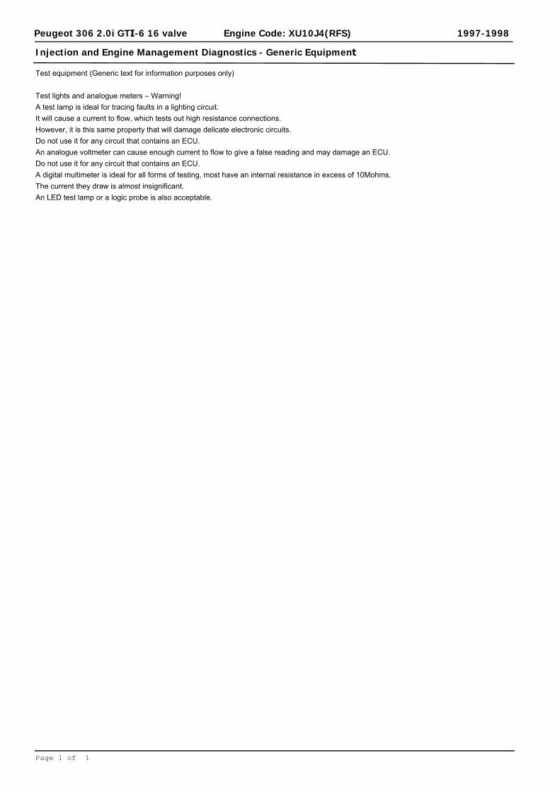
Test equipment (Generic text for information purposes only)
Test lights and analogue meters – Warning!A test lamp is ideal for tracing faults in a lighting circuit.It will cause a current to flow, which tests out high resistance connections. However, it is this same property that will damage delicate electronic circuits. Do not use it for any circuit that contains an ECU.An analogue voltmeter can cause enough current to flow to give a false reading and may damage an ECU. Do not use it for any circuit that contains an ECU.A digital multimeter is ideal for all forms of testing, most have an internal resistance in excess of 10Mohms.The current they draw is almost insignificant. An LED test lamp or a logic probe is also acceptable.
Page 1 of 1

Access trouble codes
The ECM fault memory can only be checked usingsuitable diagnostic equipment connected to thedata link connector (DLC) Fig. . 1
Erase trouble codes
Suitable diagnostic equipment required to erasedata from ECM fault memory.
Data link connector (DLC) location - Fig. 2
1
2

Timing Belt
Peugeot 306 2.0i GTI-6 16 valve 1997-1998Engine Code: XU10J4(RFS)
Replacement intervals:
Pre 08-98 models
For normal conditions
Replace every 72,000 miles
For adverse conditions
Replace every 54,000 miles
08-98/- models
For normal conditions
Replace every 80,000 miles
For adverse conditions
Replace every 54,000 miles
Engine setting positions:
TDC & locking dowel(s)
Special tools:
Camshaft timing pin(s) Peugeot No 9767.94
Crankshaft timing dowel Peugeot No 9766.98
SEEM tension gauge SEEM C.Tronic 105.5
Torque settings:
Crankshaft pulley bolts 25 Nm
Timing belt tensioner bolt(s) 20 Nm
Page 1 of 2

Timing Belt
Peugeot 306 2.0i GTI-6 16 valve 1997-1998Engine Code: XU10J4(RFS)
Procedure:
Raise & support front of vehicle.
Remove right hand road wheel and inner wing panel.
Remove auxiliary drive belt(s) & tensioner.
Support engine.
Remove engine mounting.
Remove crankshaft pulley bolt(s) ( not centre bolt ).
Remove crankshaft pulley.
Remove timing belt cover(s).
Rotate engine clockwise until holes align in camshaft gear & crankshaft pulley.
Fit camshaft timing pin.
Fit crankshaft gear timing pin.
Slacken tensioner bolt(s).
Remove timing belt.
Ensure crankshaft & camshaft locking tools are located correctly.
Fit new timing belt starting at crankshaft then water pump, lower tensioner, upper tensioner, R/H
Keep belt taut between the gears.
Apply thumb pressure to the belt at each tensioner to eliminate any play in timing pins.
Fit tension gauge between R/H camshaft & tensioner.
Adjust R/H tensioner against belt until gauge reads 45 SEEM Units
Release tensioner.
Adjust tensioner to give gauge a reading of 22±2 SEEM Units
Tighten tensioner bolt(s) to correct torque.
Adjust L/H tensioner against belt until gauge reads 32±2 SEEM Units
Tighten tensioner bolt(s) to correct torque.
Remove timing pins.
Remove tension gauge.
Turn engine 2 revolutions in direction of rotation.
Fit camshaft timing pin.
Fit crankshaft gear timing pin.
If timing pins cannot be fitted repeat tensioning procedure.
Remove timing pins.
Refit tension gauge.
Gauge should now read 53±2 SEEM Units
Remove tension gauge.
Refit remainder of components in reverse order.
Refit crankshaft pulley and tighten bolt(s) to correct torque.
Page 2 of 2

System description
Optional driver's and front passenger's airbags. 1997 : Optional front side airbags. SRS control module mounted separately. Front side airbag control module(s) mounted separately. Pyrotechnic pretensioners fitted as standard on front seat belts.
Special attention
To prevent personal injury, expansion area of all airbags MUSTremain clear.
Steering wheel spiral cable has limited rotary movement. Centralise steering before disconnecting steering column. To prevent
damage, ensure steering wheel and spiral cable DO NOT rotate beforeor during reassembly.
05/98 : Front passenger's airbag can be deactivated usingignition key.
Manufacturer recommends airbag and pyrotechnic pretensionerreplacement every 10 years.
Pyrotechnic pretensioners are electrically triggered by SRS controlmodule.
SRS warning lamps
Operation Switch ignition ON. SRS warning lamps illuminate. Lamps extinguish after 6 seconds. If not: Refer to Self-diagnosis section. If front passenger's airbag deactivated: Lamp remains illuminated. SRS control module fault memory can only be checked using diagnostic
equipment connected to the data link connector (DLC).
Disarm the system
When Fascia/instrument panel removal or replacement. Front seat belt removal or replacement. Front seat repair or replacement. Repair work around SRS components, especially airbags and
pretensioners. SRS component removal or replacement. Steering wheel/column repair or replacement. Welding operations.How Ensure ignition switched OFF. Wait 5 minutes before commencing work. Disconnect battery earth lead. Make sure accidental reconnection is
not possible. Disconnect SRS control module. Disconnect front side airbag control modules, if front side airbags
fitted. No waiting time specified by vehicle manufacturer.

Arm the system
How Ensure ignition switched OFF. Reconnect SRS control module. Reconnect front side airbag control modules, if front side airbags
fitted. Reconnect battery earth lead. Ensure driver's door is open. Keep clear of deployment area. Switch ignition ON. Check SRS warning lamp operation.
After deployment
Check All mounting brackets for SRS components. Fascia/instrument panel. Seat assemblies. Seat belts, including buckles and anchorage points. Steering wheel and column. Surrounding components and trims. SRS wiring harness and multi-plugs for charred or damaged areas.Renew All deployed airbags. Front seat belt buckles. Driver's seat belt. Front passenger's seat belt, if in operation during collision. Seat components, if damaged. Spiral cable. Steering column, if damaged. Steering wheel. Surrounding components and trims, if damaged. SRS control module. Front side airbag control module, if side airbag deployed. SRS wiring harness and multi-plugs, if charred or damaged areas
found. Fascia/instrument panel, if front passenger's airbag deployed.Disposal Vehicle manufacturer suggests that deployed SRS components are
sealed in a plastic bag and disposed of in accordance with localregulations.

Steering wheel removal and installationSpecial attention Disarm system and remove driver's airbag. Centralise steering before removing steering wheel. Spiral cable should not be allowed to rotate once steering wheel
removed. Ensure spiral cable remains centralised during reassembly.Steering wheel and airbag assembly Fig. 47536 Spiral cable alignment marks Fig. 47535
47536
47535

Remote alarm/central locking
System operation
Pressing remote control lock/unlock button Fig. [1] only activates 1 central locking.Pressing remote control lock/unlock button Fig. [1] then double 1 locking button [2] within 5 seconds activates double locking systemand alarm.
Reprogramming
WhenRemote control batteries replaced.System malfunction.If buttons operated repeatedly while vehicle out of range and systembecomes inoperative.
HowUnlock driver's door with ignition key.Press and hold lock/unlock button Fig. [1]. LED flashing [3]. 1 Wait for 20 seconds then press double locking button Fig. [2]. 1 LED stops flashing.Release lock/unlock button Fig. [1]. 1 LED remains illuminated.Press lock/unlock button Fig. [1]. LED goes out. 1 Enter vehicle.Hold remote against ignition switch.Press lock/unlock button Fig. [1]. 1 Switch ignition ON.Wait 10 seconds.Switch ignition OFF.Wait 5 seconds.Reprogramming procedure complete.Confirm programming has been successful by locking, double lockingand unlocking vehicle.
Battery replacement
Fig. 2
Immobilizer
Reprogramming
HowImmobilizer can only be programmed using diagnostic equipment.Replacement or additional keys can only be programmed usingdiagnostic equipment.

1
2

Engine will not start
ImmobilizerElectrical connections - engine/batteryIgnition systemEngine management system - connections/wiring/relaysCondition of fuel/fuel filterFuel pump/connectionsAir intake system/vacuum system - leaksEngine coolant temperature (ECT) sensorCrankshaft position (CKP) sensorManifold absolute pressure (MAP) sensorIdle air control (IAC) valveFuel pressure/delivery rate/fuel pressure regulatorInjectorsEngine control module (ECM)
Engine starts then stops
Engine management system - connections/wiring/relaysThrottle valve/sticking/linkage/positionIdle air control (IAC) valveEvaporative emission (EVAP) canister purge valveAir intake system/vacuum system - leaksEngine control module (ECM)Intake air temperature (IAT) sensor
Knocking/pinking
Air intake system/vacuum system - leaksEngine management system - connections/wiring/relaysCrankshaft position (CKP) sensorIdle air control (IAC) valveThrottle position (TP) sensorEngine control module (ECM)
Excessive fuel consumption
Engine management system - connections/wiring/relaysCondition of fuel/fuel filterFuel pump/connectionsFuel pressure/delivery rate/fuel pressure regulatorInjectorsIntake air temperature (IAT) sensorThrottle position (TP) sensorThrottle valve/sticking/linkage/positionEngine control module (ECM)Intake air temperature (IAT) sensor
CO level - too low
Air intake system/vacuum system - leaksEngine management system - connections/wiring/relaysEngine coolant temperature (ECT) sensorInjectorsHeated oxygen sensor (HO2S)
Overheating
Air intake system/vacuum system - leaksCO level

Smell of petrol
Fuel lines - leaks/damage/blockageEngine coolant temperature (ECT) sensor
Lack of power - high speed
Engine management system - connections/wiring/relaysAir intake system/vacuum system - leaksFuel lines - leaks/damage/blockageEngine coolant temperature (ECT) sensor
Lack of power - low speed
Engine coolant temperature (ECT) sensorCondition of fuel/fuel filterFuel pump/connectionsFuel pressure/delivery rate/fuel pressure regulatorInjectorsEngine control module (ECM)
CO level - too high
Engine management system - connections/wiring/relaysAir intake system/vacuum system - leaksEngine coolant temperature (ECT) sensorIntake air temperature (IAT) sensorCondition of fuel/fuel filterFuel pump/connectionsFuel pressure/delivery rate/fuel pressure regulatorEvaporative emission (EVAP) canister purge valveInjectorsHeated oxygen sensor (HO2S)
Misfire
Ignition systemEngine management system - connections/wiring/relaysEngine coolant temperature (ECT) sensorInjectorsAir intake system/vacuum system - leaksFuel lines - leaks/damage/blockage
Backfiring
Manifold absolute pressure (MAP) sensorEngine coolant temperature (ECT) sensorThrottle position (TP) sensorCondition of fuel/fuel filterFuel pump/connectionsFuel pressure/delivery rate/fuel pressure regulatorInjectors
Frequent stalling/cutting out
Air intake system/vacuum system - leaksEngine management system - connections/wiring/relaysIdle air control (IAC) valveThrottle position (TP) sensorEngine coolant temperature (ECT) sensor
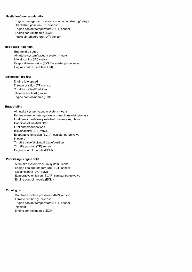
Hesitation/poor acceleration
Engine management system - connections/wiring/relaysCrankshaft position (CKP) sensorEngine coolant temperature (ECT) sensorEngine control module (ECM)Intake air temperature (IAT) sensor
Idle speed - too high
Engine idle speedAir intake system/vacuum system - leaksIdle air control (IAC) valveEvaporative emission (EVAP) canister purge valveEngine control module (ECM)
Idle speed - too low
Engine idle speedThrottle position (TP) sensorCondition of fuel/fuel filterIdle air control (IAC) valveEngine control module (ECM)
Erratic idling
Air intake system/vacuum system - leaksEngine management system - connections/wiring/relaysFuel pressure/delivery rate/fuel pressure regulatorCondition of fuel/fuel filterFuel pump/connectionsIdle air control (IAC) valveEvaporative emission (EVAP) canister purge valveInjectorsThrottle valve/sticking/linkage/positionThrottle position (TP) sensorEngine control module (ECM)
Poor idling - engine cold
Air intake system/vacuum system - leaksEngine coolant temperature (ECT) sensorIdle air control (IAC) valveEvaporative emission (EVAP) canister purge valveEngine control module (ECM)
Running on
Manifold absolute pressure (MAP) sensorThrottle position (TP) sensorEngine coolant temperature (ECT) sensorInjectorsEngine control module (ECM)

AUTO-TECH
Reference Database Application
-.33Front Camber (deg):
3.33Front Caster (deg):
4Front Toe-In (mm):
11SAI (deg):
10.67Included Angle (deg):
N/ATOOT Inside (deg):
2.5
TOOT Outside (deg):
-1.33Rear Camber (deg):
0
Rear Toe-In (mm):
Thrust Angle (deg):
Notes:
PEUGEOT 3061997-01 2.0 Litre N5 GTI6 DOHC
Wheel Alignment Specifications for:
N/A
BEFORE AFTER
Left Right Left Right
Front Camber (deg):
Front Caster (deg):
Front Toe-In (mm):
Rear Camber (deg):
Rear Toe-In (mm):
SPECIFICATIONS
Wheel Alignment Specifications for this job:
TECHINICIAN:
+ / -
+ / -
+ / -
+ / -
+ / -
+ / -
+ / - .15
1.51
.25
.5
2
.5
.5
Your Notes:
Copyright (c) 2002 AUTO-TECH Encyclopedia
All Right Reserved

PEUGEOT-TALBOT 306, 2.0i GTI-6
1996 to 1997
Notes and Illustrations
1998 cm3, 16V
Engine and cooling systemTypeCapacity (cm3) / number of cylindersCompression ratio / pressure barOil pressure barOil temperature ºCValve clearance - inlet mmValve clearance - exhaust mmFiring orderNo 1 cylinder positionThermostat opening temperature ºCRadiator cap pressure bar
Fuel systemIdle speed - manual [auto] rpmFast idle speed - manual [auto] rpmCO @ idle speed [3000 rpm] - see page VI %HC @ idle speed [3000 rpm] - see page VI ppmCO2 @ idle speed [3000 rpm] - see page VI %O2 @ idle speed [3000 rpm] - see page VI %Carburettor / fuel injection
Type / refMain jet / needleInjection pressure bar
Pump pressure barOctane rating RON
Ignition systemTypeIgnition coil
Primary resistance ohmsBallast resistor ohmsVoltage - Tmnl 15(+) to earth V
DistributorPoints gap (air gap) mmDwell angle º (%)Condenser capacity µFRotation
Ignition timing - basic [static º Crankshaft @ rpmV = Vacuum NV = No Vacuum
Total ignition advance º Crankshaft @ rpmº Crankshaft @ rpmº Crankshaft @ rpm
Centrifugal check. º Crankshaft @ rpmº Crankshaft @ rpmº Crankshaft @ rpm
Vacuum range check mbarMaximum vacuum advance º Crankshaft
Spark plugsTypeElectrode gap mm
Electrical systemBattery V / CC / RCAlternator voltage / full load current / engine rpmStarter motor current / voltage - cranking A / VStarter motor current / voltage - locked A / V
Running gearBrakes -
Front (min. friction material thickness) mmRear (min. friction material thickness) mm
TyresSaloon SizeEstate / Van SizePressure - front / rear - Saloon barPressure - front / rear - Estate / Van bar
Front suspension / wheel alignmentToe-in (+) / Toe-out (–) mm [º]CamberCastorKing pin inclination
Rear suspension / wheel alignmentToe-in (+) / Toe-out (–) mm [º]Camber
Torque wrench settingsCylinder head - stage 1 NmCylinder head - stage 2 NmCylinder head - stage 3 NmCylinder head - stage 4 NmBig-end bearings NmMain bearings NmClutch cover NmFlywheel [driveplate] NmFront hubs NmRear hubs NmWheel nuts / bolts NmSpark plugs Nm
CapacitiesEngine oil & filter litresGearbox - 4-speed [5-speed] litresAutomatic transmission - refill litresFinal drive litresCooling system litresFuel tank litres
XU10J4RS 120kW DOHC 161998 / 410.4 /_[2.2 to 5.2]800: Hyd.0: Hyd.1-3-4-2FE89 to 991.4
850±50 N/A_≤0.3≤200≥10.0_Magneti-MarelliAP 10 SEFI_3.02.8 to 3.295[U]1
Direct electronic4xBAE01 (1 per cylinder)0.7_______Computer control_Computer control__Computer control__Computer control_Eyquem/ChampionFC62LS3 / C7YCX1.20
(12L1 250)13.8 to 14.8 / _ / 3000__
1.0_
195/55x15_2.3 / 2.3_
+1.0±0.5-20’±303°20’±30’+11°±30’
+2.2±0.75-1°20’±15’
60Slacken20+ 300°401
702550 LkC3251858527
4.251.8_WT7.060
1Engine runs best on 97 RON [U]
Click on one of thebuttons above to view
data for this car. Toreturn to this screen and
make another choice,click anywhere on the
data screen.
AutomotiveTechnical
DATABOOK
306, 2.0i GTI-6 1996 to 1997
306, 2.0i GTI-6 1996 to 1997
306, 2.0i GTI-6 1996 to 1997
306, 2.0i GTI-6 1996 to 1997
306, 2.0i GTI-6 1996 to 1997
306, 2.0i GTI-6 1996 to 1997
306, 2.0i GTI-6 1996 to 1997
PEUP3062011
Engine &Cooling Fuel Ignition Electrical Running
gearTorquesettings Capacities Notes &
Illustrations
MENU HELP