2.7 Shear Strength of Unsaturated Soils - Lakehead Universityflash.lakeheadu.ca/~svanapal/papers/new...
34
2.7 Shear Strength of Unsaturated Soils D. G. FREDLUND, University of Saskatchewan, Saskatoon, Saskatchewan, Canada S. K. VANAPALLI, Lakehead University, Thunder Bay, Ontario, Canada 2.7.1 Introduction Geotechnical, geoenvironmental, and agricultural engineers, along with soil sci- entists, are interested in understanding the shear strength behavior of soils. The shear strength of a soil is required for addressing numerous problems, such as the design of foundations, retaining walls, and pavements in civil engineering applications and the resistance to traction and tillage tools for agriculture engineering applications. The shearing behavior of a saturated soil is related to one stress-state vari- able; namely, the effective stress, s¢, defined as (s- u w ). The term, s, is the total stress, and u w is the pore-water pressure. The pore-water pressures in saturated soils are typically positive or zero. Shear strength tests for saturated soils can be performed in most geotechnical and agricultural laboratories. Detailed test procedures related to the determination of the shear strength of saturated soils are not discussed in this section. Standard testing procedures as per American Society for Testing and Ma- terials (ASTM) methods for various shear strength tests for saturated soils are sum- marized in D2850-95e1, D3080-98, D2166-98a, and D4767-95 (ASTM, 1995a, b, 1998a, b). More information related to the test procedures is available in Lambe (1951), Holtz and Kovacs (1981), and Bishop and Henkel (1962). Soils in an unsaturated state have negative pore-water pressures. The differ- ence between the pore-air pressure, u a , and pore-water pressure, u w , is referred to as matric suction (u a - u w ). Unlike saturated soils, the mechanical behavior of un- saturated soils depends on two independent stress-state variables. These variables are the stress tensor, (s- u a ), which is referred to as net normal stress, and matric suction (u a - u w ) (Fredlund & Rahardjo, 1993). Soil behavior is independent of the individual valves of u a , u w , or the total stress, s, so long as the stress-state variables, (s- u a ) and (u a - u w ), are invariant. A special case of this principle, that the water content of unconfined soil specimens in a pressure membrane apparatus is uniquely dependent on the matric suction (u a - u w ), regardless of the individual values of u a and u w , is familiar to soil physicists. The complete form of the stress state for an unsaturated soil in terms of two independent stress tensors can be represented in a matrix form as shown below: (s x - u a ) t yx t zx t xy (s y - u a ) t zy [2.7–1] t xz t yz (s z - u a ) 1
Transcript of 2.7 Shear Strength of Unsaturated Soils - Lakehead Universityflash.lakeheadu.ca/~svanapal/papers/new...

2.7 Shear Strength of Unsaturated SoilsD. G. FREDLUND, University of Saskatchewan, Saskatoon, Saskatchewan, Canada
S. K. VANAPALLI, Lakehead University, Thunder Bay, Ontario, Canada
2.7.1 Introduction
Geotechnical, geoenvironmental, and agricultural engineers, along with soil sci-entists, are interested in understanding the shear strength behavior of soils. The shearstrength of a soil is required for addressing numerous problems, such as the designof foundations, retaining walls, and pavements in civil engineering applications andthe resistance to traction and tillage tools for agriculture engineering applications.
The shearing behavior of a saturated soil is related to one stress-state vari-able; namely, the effective stress, s¢, defined as (s - uw). The term, s, is the totalstress, and uw is the pore-water pressure. The pore-water pressures in saturated soilsare typically positive or zero. Shear strength tests for saturated soils can be performedin most geotechnical and agricultural laboratories. Detailed test procedures relatedto the determination of the shear strength of saturated soils are not discussed in thissection. Standard testing procedures as per American Society for Testing and Ma-terials (ASTM) methods for various shear strength tests for saturated soils are sum-marized in D2850-95e1, D3080-98, D2166-98a, and D4767-95 (ASTM, 1995a, b,1998a, b). More information related to the test procedures is available in Lambe(1951), Holtz and Kovacs (1981), and Bishop and Henkel (1962).
Soils in an unsaturated state have negative pore-water pressures. The differ-ence between the pore-air pressure, ua, and pore-water pressure, uw, is referred toas matric suction (ua - uw). Unlike saturated soils, the mechanical behavior of un-saturated soils depends on two independent stress-state variables. These variablesare the stress tensor, (s - ua), which is referred to as net normal stress, and matricsuction (ua - uw) (Fredlund & Rahardjo, 1993). Soil behavior is independent of theindividual valves of ua, uw, or the total stress, s, so long as the stress-state variables,(s - ua) and (ua - uw), are invariant. A special case of this principle, that the watercontent of unconfined soil specimens in a pressure membrane apparatus is uniquelydependent on the matric suction (ua - uw), regardless of the individual values of uaand uw, is familiar to soil physicists.
The complete form of the stress state for an unsaturated soil in terms of twoindependent stress tensors can be represented in a matrix form as shown below:
(sx - ua) tyx tzxtxy (sy - ua) tzy [2.7–1]ó txz tyz (sz - ua) û
1

and
(ua - uw) 0 00 (ua - uw) 0 [2.7–2]ó 0 0 (ua - uw) û
Figure 2.7–1 illustrates two independent stress tensors in an unsaturated soil.The three normal stresses, sx, sy, and sz are mutually orthogonal with respect tox, y, and z directions. The six shear-stress components acting on the boundaries aresymmetric, tij = tji. Because of this, it is possible to choose an orientation of thex-y-z axes, known as the principal stress space. The shear stresses vanish in the prin-cipal stress space, and the net applied stress tensor for this condition in a matrix formis shown below.
(s1 - ua) 0 00 (s2 - ua) 0 [2.7–3]ó 0 0 (sz - ua) û
The three principal stresses, s1 (major principal stress), s2 (intermediate prin-cipal stress), and s3 (minor principal stress), respectively, are applied to the bound-aries, and the diagonal components of the principle stress tensor represent theeigenvalues of the general stress tensor from continuum mechanics principles.
The shear strength of an unsaturated soil is conventionally measured load-ing a cylindrical specimen in compression using triaxial shear-testing equipment.The pore pressures, ua and uw, and principal stresses, s1, s2, and s3, are indepen-dently controlled (similar to a pressure plate apparatus) in the triaxial cell of the
2 CHAPTER 2
Fig. 2.7–1. The stress state variables for an unsaturated soil using the combination of (s - ua) and (ua- uw).

shear-testing equipment. Typical constraints in this equipment are that s2 is equalto s3, and s3 is less than s1. The resulting deviator stress (s1 - s3) due to speci-men loading is measured in compression. The shear stresses are always directly pro-portional to the deviator stress (s1 - s3) for any given coordinate axis system.
The direct shear apparatus is another experimental apparatus to measuresoil-shearing behavior. Unlike the triaxial shear apparatus, where all applied stressesare principal stresses, the direct shear apparatus has one applied normal stress com-ponent, sn, and the shear resistance, t, is measured perpendicular to sn. More de-tails about the triaxial and direct shear equipment and Mohr–Coulomb approachfor interpreting the unsaturated shear strength behavior are described later.
This section discusses the basic principles and experimental procedures re-lated to the measurement of the shear strength of unsaturated soils using triaxial anddirect shear apparatus. The procedures for estimating the shear strength of an un-saturated soil from the soil water characteristic curve and the saturated shearstrength parameters are also discussed.
2.7.2 Shear Strength Equation for Unsaturated Soils
The shear strength behavior of an unsaturated soil can be interpreted usingtriaxial or direct shear test results. The shear strength of an unsaturated soil is de-termined using “identical” specimens. The soil specimens need to be prepared atthe same initial water content and dry density conditions to qualify as identical spec-imens (Fredlund & Rahardjo, 1993).
In a typical triaxial test series, the shear strength is determined over a rangeof matric suction values using the same net normal stress (s - ua). If the major prin-cipal stress, s1, and minor principal stress, s3, acting on a specimen are known, theshear stress, s, and the normal stress, sn, acting on a plane oriented at any givenangle, s, can be calculated relative to the principal axes. Also, Mohr’s circles canbe plotted with respect to failure conditions for combinations of s1 and s3 and dif-ferent values of matric suction. Figure 2.7–2 shows the failure envelope drawn tan-gent to the Mohr’s circles.
Fredlund et al. (1978) proposed the equation shown below for interpretingthe shear strength of unsaturated soils in terms of two independent stress-state vari-ables, (s - ua) and (ua - uw):
tff = c¢ + (sf - ua)f tanf¢ + (ua - uw)f tanfb [2.7–4]
where tff is the shear stress on the failure plane at failure, c¢ is the intercept of theextended Mohr–Coulomb failure envelope on the shear stress axis where the netnormal stress and the matric suction at failure are equal to zero—it is also referredto as effective cohesion, (sf - ua)f is the net normal stress state on the failure planeat failure, uaf is the pore-air pressure on the failure plane at failure, f¢ is the angleof internal friction associated with the net normal stress state variable, (sf - ua)f,(ua - uw)f is the matric suction on the failure plane at failure, and fb is the angle in-dicating the rate of increase in shear strength relative to the matric suction, (ua -uw)f.
THE SOLID PHASE 3

The shear strength equation for an unsaturated soil (Eq. [2.7–4]) is also validfor direct shear tests. This equation is an extension of the Mohr–Coulomb shearstrength equation for a saturated soil.
The shear strength envelope for unsaturated soils was originally proposed asa planar surface in nature based on a limited set of data available in the literature(Fredlund et al., 1978). Later experimental evidence by several investigators es-tablished that the shear strength for unsaturated soils is nonlinear when tested overa large range of suction (Gan et al., 1988; Escario & Juca, 1989). The Fredlund etal. (1978) equation is valid for interpreting data for both linear and nonlinear shearstrength envelopes.
2.7.3 Triaxial Shear Tests for Unsaturated Soils
Conventional triaxial and direct shear equipment used to measure the shearstrength of saturated soils requires modifications when testing the shear strengthof unsaturated soils. These modifications must accommodate independent mea-surement (or control) of the pore-air pressure, ua, and the pore-water pressure, uw.The axis-translation technique forms the basis for these modifications. Laboratorytesting of unsaturated soils with matric suction values >101.3 kPa (i.e., 1 atm) canthen be undertaken without encountering cavitation problems (Hilf, 1956).
The axis-translation technique allows the pore-water pressure, uw, in an un-saturated soil to be measured (or controlled) using a ceramic disk with fine pores
4 CHAPTER 2
Fig. 2.7–2. Shear strength envelope for unsaturated soils (from Fredlund & Rahardjo, 1993).

(i.e., a high air-entry disk). These disks are used in unsaturated soil testing in placeof conventional porous disks used in saturated soil testing. The ceramic disk mustbe epoxied around the edge to form a seal with the base pedestal. The high air-entrydisk acts as a semipermeable membrane that separates the air and water phases. Theseparation of the water and air phases can be achieved only when the air-entry valueof the disk is greater than the matric suction of the soil. The air-entry value refersto the maximum matric suction to which the high air-entry disk can be subjectedbefore free air passes through the disk.
Various types of triaxial test methods are defined on the basis of drainage con-ditions during the application of confining pressure and during the application ofthe shear stress. The net total confining pressure (s3 - ua) generally remains con-stant during shear. The axial stress is continuously increased until a failure condi-tion is reached. The axial stress generally acts as the total major principal stress,s1, in the axial direction, while the isotropic confining pressure acts as the total minorprincipal stress, s3 [i.e., (s2 = s3)].
The shear strength of unsaturated soils is interpreted in terms of the two stress-state variables, (s - ua) and (ua - uw), if the failure pore pressures are measured.Such an approach is referred to as a stress-state-variable approach for unsaturatedsoils. The shear strength has to be interpreted in terms of total stresses at failure ifthe pore pressures are not measured or controlled. The total stress approach for un-saturated soils should be applied in the field only for the case where it can be rightlyassumed that the strength measured in the laboratory has relevance to the fielddrainage conditions. For example, rapid loading of a fine-grained soil can be as-sumed to be representative of undrained loading conditions.
The air, water, or total volume changes may or may not be measured duringshear. A summary of various triaxial testing conditions, together with necessary mea-surements, is given in Table 2.7–1. The air, water, or total volume changes may ormay not be measured during shear.
2.7.3.1 Test Procedures for Triaxial Tests
Figure 2.7–3 shows the assemblage of a triaxial cell used for testing the shearstrength of an unsaturated soil. The installation of a high air-entry disk onto the tri-axial cell base pedestal requires modifications to accommodate the pore-air pres-sure channel (i.e., valve C), the high air-entry disk, and the grooved water com-partment below the disk (Fig. 2.7–4). The grooves inside the water compartment
THE SOLID PHASE 5
Table 2.7–1. Different triaxial tests for unsaturated soils.
Drainage Shearing process†
Consolidation Pore Pore Soilprior to Pore Pore air pres- water pres- volume
Test methods shearing process air water sure, ua sure, uw change, V
Consolidated drained Yes Yes Yes C C MConstant water content Yes Yes No C M MConsolidated undrained Yes No No M M --Undrained compression No No No -- -- --Unconfined compression No No No -- -- --
† M = measurement, C = controlled.

serve as water channels for flushing air bubbles that might be trapped or have ac-cumulated as a result air diffusion. The high air-entry disk should be properly sealedonto the base pedestal using an epoxy resin seal around its circumference.
The high air-entry disk must be fully saturated before use in testing the shearstrength of an unsaturated soil specimen, either in a triaxial shear test or a directshear test. A head of distilled water can be applied to the high air-entry disk in thetriaxial or direct shear equipment chamber. The water is then allowed to flowthrough the disk for a period of approximately 1 h, using an air pressure that is ap-proximately equal to several times the air-entry value (i.e., five or six times). Theair bubbles collected during the process from below the disk are flushed out. Thisprocedure dissolves the air present in the disk and ensures full saturation of the highair-entry disk.
Typical diameters recommended for testing the shear strength of fine-grainedand coarse-grained soil specimens are 38 and 76 mm, respectively. The ratio oflength to diameter is recommended to be equal to 2. This value is similar to test-
6 CHAPTER 2
Fig. 2.7–3. Modified triaxial cell for testing the shear strength of unsaturated soils (from Fredlund &Rahardjo, 1993).

ing the shear strength of saturated soil specimens. The unsaturated soil specimensused for determining the shear strength, either undisturbed or compacted, are gen-erally saturated before testing. Saturation is achieved in triaxial shear equipmentby incrementally increasing the pore-water pressure, uw. At the same time, the con-fining pressure, s3, is increased incrementally to maintain a constant effective stress(s3 - uw) in the specimen. As a result, the pore-air pressure increases and the pore-air volume decreases by compression and dissolution into the pore-water. The si-multaneous pore-water and confining pressure increases are referred to as back pres-suring the soil specimen.
Valve A in the base plate is used to control the pore-water pressure and to mea-sure the water-volume change during a drained shear test (Fig. 2.7–4). Valve A canbe connected to a twin-burette volume-change indicator (Bishop & Donald, 1961;Bishop & Henkel, 1962). Valve B on the base plate is used to measure the pore-water pressure during an undrained test. It can also be used to measure the prescribedpore-water pressure during a drained test. The pore-water pressure can be measuredusing a pressure transducer.
THE SOLID PHASE 7
Fig. 2.7–4. Triaxial base plate for unsaturated soil testing. (a) Plan view of the base plate with its out-let ports; (b) cross-section of a base plate with a high air-entry disk (from Fredlund & Rahardjo, 1993).

An arrangement for pore-air pressure control using triaxial equipment isshown in Fig. 2.7–3. A 3.2-mm (1/8-in.) thick, coarse corundum disk is placed be-tween the soil specimen and the loading cap. The disk is connected to the pore-airpressure control through a hole drilled in the loading cap and connected to a small-bore polyethylene tube. The pore-air pressure can be controlled at a desired pres-sure using a pressure regulator from an air supply. The measurement of pore-air pres-sure can be achieved using a small pressure transducer, preferably mounted on theloading cap. When measuring pore-air pressure, the air volume of the measuringsystem should be kept to a minimum to obtain accurate measurements. Pore-air pres-sure is difficult to measure because of the capability of air to diffuse through rub-ber membranes, water, polythene tubing, and other materials. The pore-air diffusesthrough water if the axis-translation technique is extended for a long time. A dif-fused air-volume indicator (DAVI) can be used in conjunction with the measuringsystem to flush diffused air from below the high air-entry disk. It is also possibleto measure the volume of diffused air. Such a procedure enables a more accuratemeasurement of volume changes (Fredlund & Rahardjo, 1993).
The layout of the plumbing for the control board is shown in Fig. 2.7–5. Thepore-air pressure line controls the pore-air pressure. In the case where the pore-airpressure is measured, a pressure transducer can be connected to the data-acquisi-tion system through the base plate.
The initial confining air and water pressures to be applied to the soil speci-men can be set on the pressure regulators before preparing the specimen. The con-
8 CHAPTER 2
Fig. 2.7–5. Schematic diagram of the control board and plumbing layout for the modified triaxial ap-paratus (from Fredlund & Rahardjo, 1993).

fining air and water pressures are applied to form the required stress-state variables,(s3 - ua) and (ua - uw), to the specimen through Valves D, C, and A, respectively(Fig. 2.7–5). An initial water pressure of 30 kPa or greater is desirable to providesufficient pressure to flush air from the base plate.
2.7.3.1.a Consolidated Drained Test
The consolidated drained (CD) test is a common test conducted in the labo-ratory to measure the shear strength of an unsaturated soil. Figure 2.7–6 shows thestress conditions during the consolidated drained triaxial compression test. In thistype of test, the soil is consolidated to a stress state representative of the stress rangelikely to be encountered in the field or in design. The soil specimen in the triaxialcell is generally consolidated under an isotropic confining pressure of s3, while thepore-air and pore-water pressures are controlled at pressures of ua and uw, respec-tively, by opening Valves D, C, and A (Fig. 2.7–5). Valves B and E are always closedduring the test, except during the flushing of diffused air from the base plate. Thewater pressure, applied to the base plate, is registered on a transducer.
The vertical deflection and the deformation are periodically monitored to mea-sure the overall volume change of the specimen. The volume of water flowing into(or out from) the specimen is recorded on the twin-burette volume-change indica-tor. Therefore, the three-way valves, T1 and T2, are always open during the test, ex-cept during the process of flushing diffused air from the base plate (Fig. 2.7–5). Theair-volume change is generally not measured. Consolidation is assumed to havereached an equilibrium condition when there is no longer a tendency for the over-all volume change or the flow of water from the specimen. At the end of the con-solidation process, the soil specimen has a net confining pressure of (s3 - ua) andmatric suction of (ua - uw). The specimen is then sheared by axial compression, atan appropriate strain rate. More details with respect to the strain rates of shearstrength testing are discussed below.
Diffused air is generally flushed from the base plate once a day during bothconsolidation and shearing. The frequency of the diffused-air measurement dependsprimarily on the applied air pressure. For a low applied air pressure, the diffused-air volume can be measured less frequently. In any case, the diffused-air volumeshould be measured before changing applied pressures. The water-volume-changecorrection, due to the diffused air volume, becomes necessary whenever tests ex-tend over a period of several days.
The soil specimen is compressed in the axial direction by applying a devia-tor stress [i.e., (s1 - s3)] during the shearing process. The drainage valves for bothpore air and pore water remain open during the shearing stage (i.e., under drainedconditions). The pore-air and pore-water pressures are usually controlled at con-stant pressures (i.e., their pressures at the end of consolidation). The deviator stressis applied slowly to prevent the development of excess pore-air pressure or pore-water pressure in the soil. The net confining pressure, (s3 - ua), and the matric suc-tion, (ua - uw), remain constant throughout the test until failure conditions arereached, as shown in Fig. 2.7–6, that is, (s3 - ua)f = (s3 - ua) and (ua - uw)f = (ua- uw). The deviator stress (s1 - s3) keeps changing during shear until the net majorprincipal stress reaches a value of (s1 - ua)f at failure.
THE SOLID PHASE 9

10 CHAPTER 2

2.7.3.1.b Constant Water-Content Tests
For the constant water content (CW) test, the specimen is first consolidatedand then sheared, with the pore-air phase allowed to drain while the pore-water phaseis in an undrained mode. The consolidation procedure is similar to that of the con-solidated drained test. When equilibrium is reached at the end of consolidation, thesoil specimen has a net confining pressure of (s3 - ua) and a matric suction of (ua- uw). The specimen is sheared by increasing the deviator stress until failure isreached. During shear, the drainage valve for the pore air remains open (i.e., underdrained conditions). The pore-air pressure, ua, is maintained at the pressure appliedduring consolidation; that is, Valve C is open during consolidation and shear (Fig.2.7–5). The pore-water pressure is measured using a pressure transducer mountedon the base plate.
During shear, under undrained water-phase conditions, the diffused air vol-ume should be measured. In this case, the water pressure in the base plate shouldbe recorded before the flushing process and reset after flushing. The water in thepore-water pressure control line should first be subjected to the same pressure asrecorded in the base plate. Valves A, T1, and T2 should remain closed, while ValveE is opened when adjusting the water-line pressure. The air back pressure in thediffused air-volume indicator should be adjusted to a pressure slightly lower thanthe recorded water pressure in the base plate, while Valve B remains closed. WhenValve A is opened, the water in the base plate will quickly equalize to the pore-waterpressure control line. The diffused air is then removed from the base plate by mo-mentarily opening Valve B, which produces a pressure difference across the baseplate. Valves A and B are closed at the end of the diffused air-volume measurement.The undrained pore-water pressure is then returned to the value existing before theflushing process. If the diffused-air removal is performed in a short period of time,disturbance to the undrained condition of the specimen should be minimal.
2.7.3.1.c Consolidated Undrained Tests with Pore-Pressure Measurements
For the consolidated undrained (CU) test, the soil specimen is first consoli-dated following the procedure described for the consolidated drained test. After equi-librium conditions have been established under the applied pressures (i.e., s3, ua,and uw), the soil specimen is sheared under undrained conditions with respect tothe air and water phases. Undrained conditions during shear are achieved by clos-ing Valves A, B, and C (Fig. 2.7–5).
The pressure transducer should be mounted on the loading cap, if possible,for measuring pore-air pressure changes. However, it is difficult to maintain anundrained condition for the pore air because of its capability to diffuse through thepore water, the rubber membrane, and the water in the high air-entry disk.
The diffused-air volume can be measured in a manner similar to that used dur-ing the CW test. These tests are generally not performed because of the problemsassociated with air diffusion.
2.7.3.1.d Undrained Tests
The procedure for performing an undrained test on an unsaturated soil spec-imen using the triaxial shear apparatus is similar to the procedure used for per-
THE SOLID PHASE 11

forming a typical undrained test on a saturated soil specimen. The unsaturated soilspecimen is tested at its initial water content or matric suction. In other words, theinitial matric suction in the specimen is not relaxed or changed before commenc-ing the test. Both confined and unconfined compression triaxial tests can be con-ducted, and the shear strength contribution due to suction can be interpreted in termsof total stresses.
Matric suction changes in an unsaturated soil under undrained loading con-ditions are analogous to the changes in pore-water pressures in saturated soilsunder similar conditions of loading. Volume change in unsaturated soils underundrained loading is due mainly to the compression of air. Undrained pore pres-sures are assumed to be generated immediately after loading.
Figure 2.7–7 shows the development of pore-air and pore-water pressures dur-ing undrained compression under an applied isotropic stress. Skempton (1954) andBishop (1954) introduced the concept of pore-pressure parameters. Tangent pore-pressure parameters for air and water phases for undrained loading conditions are:
Ba = dua/ds3 [2.7–5]
Bw = duw/ds3 [2.7–6]
where Ba is the tangent pore-air pressure parameter; dua is the increase in pore-airpressure due to an infinitesimal increase in isotropic pressure, ds3; ds3 is the in-finitesimal increase in isotropic pressure; Bw is the tangent pore-water pressure pa-
12 CHAPTER 2
Fig. 2.7–7. Development of pore pressures due to undrained loading conditions (from Fredlund & Ra-hardjo, 1993).

rameter; and duw is the increase in pore-water pressure due to an infinitesimal in-crease in isotropic pressure, ds3.
Pore-pressure parameters Ba and Bw take into account the changes in matricsuction occurring under increasing total stress. The pore-pressure parameters aremainly a function of degree of saturation, compressibility, and loading and changeat varying rates in response to the applied total stress. Ba and Bw are less than oneat degrees of saturation less than 100%, and at complete saturation, Ba equals Bwand approach one. The matric suction (ua - uw) in soil approaches zero once thesoil approaches saturation under the applied loading condition.
For a compacted soil, the initial pore-air pressure can be assumed to be zero.The negative pressure in the soil with reference to atmospheric pressure is the ma-tric suction. Under the application of total stress, the degree of saturation of the soilincreases because of a decrease in total volume. Changes in pore-air pressure, dua,and pore-water pressure, duw, due to a finite change in total isotropic pressure, s3,can be computed knowing the initial conditions of the soil (Hasan & Fredlund, 1980;Fredlund & Rahardjo, 1993). A marching-forward technique can be applied withfinite increments of total stress to estimate the changes in pore pressures com-mencing from a known initial unsaturated condition of the soil.
Matric-suction changes can also occur in an unsaturated soil during theshearing stage of triaxial loading conditions. These changes are expressed in termsof D pore-pressure parameters. Tangent pore-pressure parameters are measuredunder triaxial undrained loading conditions. The pore-air pressure parameter, Da,can be defined as:
Da = dua/[d(s1 - s3)] [2.7–7]
where Da is the tangent pore-air pressure for uniaxial, undrained loading; ds1 is thefinite increment in major principal stress; d(s1 - s3) is the finite increment in de-viator stress.
The pore-water pressure parameter, Dw, is defined as:
Dw = duw/[d(s1 - s3)] [2.7–8]
In a triaxial test, the total stress increment ds2 equals ds3. The major prin-cipal stress increment of total stress, ds1, is applied axially. The development ofpore pressures in the undrained triaxial test are influenced both by the total stressincrement, ds3, and from the change in the deviator stress, d(s1 - s3).
The changes in pore pressures are given by:
dua = Bads3 + Dad(s1 - s3) [2.7–9]
duw = Bwds3 + Dwd(s1 - s3) [2.7–10]
Equations [2.7–9] and [2.7–10] can be expressed in a different form as:
dua = Ba[ds3 + Aad(s1 - s3)] [2.7–11]
duw = Bw[ds3 + Awd(s1 - s3)] [2.7–12]
THE SOLID PHASE 13

where:BaAa = Da [2.7–13]
BwAw = Dw [2.7–14]
Shear strength can be related to the total stresses when the pore pressures atfailure are unknown.
Unconfined Compression Test. The unconfined compression test is a spe-cial case of the undrained test and is usually performed in a simple loading frame.The soil specimen is sheared by applying an axial load until failure is reached. Thecompressive load is applied quickly (i.e., a strain rate of 1.2 mm min-1) to main-tain undrained conditions. Theoretically, this should apply to both the pore-air andpore-water phases. The pore-air and pore-water pressures are not commonly mea-sured during compression. The deviator stress (s1 - s3) is equal to the major prin-cipal stress, s1, since the confining pressure, s3, is equal to zero. The deviator stressat failure is referred to as the unconfined compressive strength, qu.
Soil samples in the field can remain saturated in some situations (i.e., S is equalto 100%), although the pore-water pressure is negative (i.e., pore-water pressuresless than the air-entry value). The pore-water pressure can be negative because thesoil has been taken from some distance above the groundwater table, or it can benegative due to the release of overburden pressure, or both.
Confined Compression Test. The unconfined compressive strength is as-sumed to be equal to twice the undrained shear strength, cu. However, as the con-fining pressure increases, the undrained shear strength for the unsaturated soil alsoincreases. As a result, the compressive-strength value may not satisfactorily ap-proximate the undrained shear strength, cu, at a confining pressure greater than zero.In the next paragraph, explanations are provided such that the confined compres-sion test can be interpreted in terms of stress-state variables.
Four “identical” soil specimens are subjected to different confining pressuresduring the undrained tests shown in Fig. 2.7–8. The pore-air pressure, Ba, and pore-water pressure, Bw, in these soil specimens increase with the increase in confiningpressure. The change in matric suction that arises in the specimen due to the ap-plication of confining pressure, s3, can be either computed using the theory ofundrained pore-pressure parameters (i.e., Ba and Bw parameters) or measured at theend of the test (Hasan & Fredlund, 1980; Fredlund & Rahardjo, 1993).
The shear strength increases with an increasing confining pressure. The ma-tric suction in the soil decreases with an increase in the degree of saturation ac-companied by a reduction in the volume. The four identical soil specimens arebrought to different initial states of stress because of the changes in pore pressuresunder undrained loading conditions. In undrained loading conditions for unsaturatedsoils, the increase in shear strength caused by an increase in confining pressure isgreater than the reduction of shear strength associated with the decrease in matricsuction. In Fig. 2.7–8, the diameter of the Mohr circles increases with an increasein confining pressure. The envelope defines a curved relationship between the shearstrength and total normal stress for unsaturated soils tested under undrained con-ditions. Once the soil becomes saturated under the application of confining pres-
14 CHAPTER 2

sure (i.e., Ba and Bw equals 1), a horizontal envelope develops with respect to theshear strength axis.
Under saturated conditions, where a single stress state variable (s - uw) con-trols the strength, an increase in the confining pressure will be equally balanced bya pore-water pressure increase. The effective stress, (s3 - uw), remains constant re-gardless of the applied confining pressure, s3. Once the soil is saturated, the shearstrength behavior is in accordance with the fu = 0 concept (Skempton, 1948).
The pore-pressure changes due to the application of deviator stress (i.e., Daand Dw parameters) are commonly neglected in undrained tests for unsaturated soils(Fredlund & Rahardjo, 1993). The shear strength contribution due to suction, fb,can be estimated assuming a planar-failure envelope both for confined and uncon-fined compression tests. These details are provided in a later section.
2.7.4 Direct Shear Tests for Unsaturated Soils
Direct shear tests on unsaturated soil specimens are commonly conducted inconsolidated drained conditions. Typical dimensions recommended for testing theshear strength of fine-grained and coarse-grained soil specimens is 50 by 50 by 25mm and 100 by 100 by 30 mm, respectively. Figure 2.7–9 provides the details re-lated to the experimental setup, including the installation of a high air-entry diskin the base of the shear box. A cross-sectional view of the direct shear equipmentis shown in Fig. 2.7–10.
A saturated soil specimen is placed in the direct shear box and consolidatedunder a vertical normal stress, s. During the process of consolidation, pore-air andpore-water pressures must be controlled at selected pressures. The axis-translationtechnique can be used to impose a desired value of matric suction. The pore-waterpressure can be controlled below the specimen using a high air-entry disk. At the
THE SOLID PHASE 15
Fig. 2.7–8. Shear stress vs. total normal stress relationship for the undrained tests (from Fredlund & Ra-hardjo, 1993).

16 CHAPTER 2

THE SOLID PHASE 17
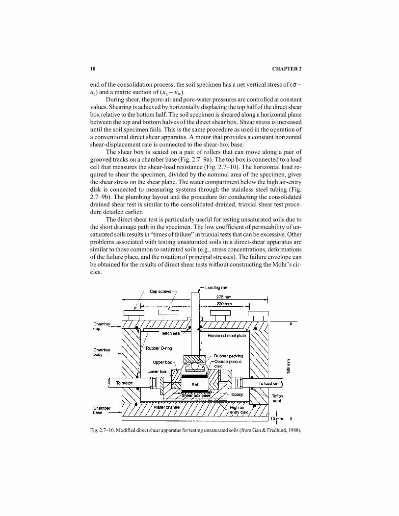
end of the consolidation process, the soil specimen has a net vertical stress of (s -ua) and a matric suction of (ua - uw).
During shear, the pore-air and pore-water pressures are controlled at constantvalues. Shearing is achieved by horizontally displacing the top half of the direct shearbox relative to the bottom half. The soil specimen is sheared along a horizontal planebetween the top and bottom halves of the direct shear box. Shear stress is increaseduntil the soil specimen fails. This is the same procedure as used in the operation ofa conventional direct shear apparatus. A motor that provides a constant horizontalshear-displacement rate is connected to the shear-box base.
The shear box is seated on a pair of rollers that can move along a pair ofgrooved tracks on a chamber base (Fig. 2.7–9a). The top box is connected to a loadcell that measures the shear-load resistance (Fig. 2.7–10). The horizontal load re-quired to shear the specimen, divided by the nominal area of the specimen, givesthe shear stress on the shear plane. The water compartment below the high air-entrydisk is connected to measuring systems through the stainless steel tubing (Fig.2.7–9b). The plumbing layout and the procedure for conducting the consolidateddrained shear test is similar to the consolidated drained, triaxial shear test proce-dure detailed earlier.
The direct shear test is particularly useful for testing unsaturated soils due tothe short drainage path in the specimen. The low coefficient of permeability of un-saturated soils results in “times of failure” in triaxial tests that can be excessive. Otherproblems associated with testing unsaturated soils in a direct-shear apparatus aresimilar to those common to saturated soils (e.g., stress concentrations, deformationsof the failure place, and the rotation of principal stresses). The failure envelope canbe obtained for the results of direct shear tests without constructing the Mohr’s cir-cles.
18 CHAPTER 2
Fig. 2.7–10. Modified direct shear apparatus for testing unsaturated soils (from Gan & Fredlund, 1988).

2.7.5 Failure Criteria for Unsaturated Soils
The shear strength test is performed by loading a soil specimen with increasingapplied loads such that a failure load is determined from the stress vs. strain rela-tionships. Stress is defined as the load divided by area of the specimen. Normal strainfor a triaxial specimen is defined as the ratio of the change in length to the origi-nal length. Shear displacement rather than strain is used for direct shear testing. Sim-ilar definitions are used in the interpretation of shear strength results for saturatedsoils. The load on the specimen is generally measured using a loading cell, and thestrain is measured using a linear vertical displacement transducer (LVDT). The stressvs. strain data are collected using a personal computer with a data-logging system.
Various types of failure criteria for unsaturated soils were used in the litera-ture (Bishop et al., 1960; Satija & Gulhati 1979). Typical stress–strain curves forconsolidated drained triaxial tests are shown in Fig. 2.7–11. The curves show anincrease in the maximum deviator stress as the net confining pressure (s3 - ua) isincreased, while the matric suction (ua - uw) remains constant. The volume changeof the soil specimen during shear is usually measured with respect to the initial soilvolume, that is, -V/Vo, and plotted vs. strain (Fig. 2.7–11c). Compression is con-ventionally given a negative sign, while expansion has a positive sign. Figure2.7–11b presents a plot of gravimetric water-content change vs. strain where an in-crease in water content is given a positive sign.
In certain cases, the failure load is not well defined, as shown in Fig. 2.7–12.In this case, an arbitrary strain (e.g., 12%) is selected to represent failure conditions.The limiting strain-failure criterion is used when large deformations are requiredto mobilize the maximum shear stress. This criterion can also be used in direct sheartesting. From a practical perspective, the different failure criteria produce similarshear strength parameters for unsaturated soils.
2.7.5.1 Strain Rates for Triaxial and Direct Shear Tests
The shear strength testing of unsaturated soils is generally performed at a con-stant rate of strain. An appropriate strain must be selected before commencing atest. In undrained shear, the selected strain must ensure equalization of pore pres-sures throughout the specimen. In drained shear, the selected strain must ensure com-plete dissipation of the pore pressures. The estimation of strain rate for testing soilsin triaxial and direct shear can be made partly on the basis of the experimental ev-idence and partly on the basis of theory.
The strain rate for triaxial testing can be defined as the rate at which a soilspecimen is axially compressed:
e = ef/ tf [2.7–15]
where is the strain rate for shearing a specimen in the triaxial test, f is the strain ofthe soil specimen at failure, and tf is the time required to fail the soil specimen ortime to failure.
The rate of horizontal shear displacement in a direct-shear displacement testis analogous to the strain rate in a triaxial shear test. The horizontal shear-dis-
THE SOLID PHASE 19

20 CHAPTER 2
Fig. 2.7–11. Consolidated drained triaxial test results on Dhanauri clay. (a) Stress vs. strain curve; (b)water content change vs. strain curve; (c) soil volume change vs. strain curve (modified after Satija& Gulhati, 1979).
Fig. 2.7–12. Strain limit as a failure criterion.

THE SOLID PHASE 21
placement rate can be defined as the relative rate at which the top and the bottomhalves of the direct shear box are displaced.
d = dh/tf [2.7–16]
where d is the horizontal shear-displacement rate for a direct shear test, and dh isthe horizontal displacement of the soil specimen at failure.
The strain at failure depends on the soil type and the stress history of the soil.Tables 2.7–2 and 2.7–3 present typical values of strain at failure, obtained from nu-merous triaxial and direct shear testing programs on unsaturated soils. This infor-mation can be of value as a guide when attempting to establish a suitable strain rate.The direct shear test has the advantage that a thin specimen can assist in expedit-ing testing.
The strain rate for testing can also be estimated from a theoretical standpoint.The computed strain is approximate because of the assumptions involved in the the-ory and the difficulties in accurately assessing relevant soil properties. More de-tails of the theory associated with the selection of strain rates are available inBishop and Gibson (1963), Gibson and Henkel (1954), Ho and Fredlund (1982a),and Fredlund and Rahardjo (1993).
2.7.6 Interpretation of Drained Test Results UsingMultistage Testing Procedures
Multistage testing can be performed using triaxial or direct shear testing equip-ment for consolidated drained tests. In this method, the stress path is altered to max-imize the amount of shear strength information that can be obtained from one spec-imen. This method has the advantage of eliminating the effect of soil variability onthe test results. For unsaturated soils, multistage testing has been performed in con-junction with a consolidated drained type of test using triaxial shear equipment. Inthese types of tests, the net confining pressure (s3 - ua) is usually maintained con-stant, while the matric suction is varied from one stage to another. However, themultistage testing is also applicable when using the constant water content or theconsolidated undrained test procedure.
Ho and Fredlund (1982b) proposed a cycling loading procedure for multistagetesting. Figure 2.7–13a illustrates this procedure for a decomposed rhyolite. Therhyolite specimen was tested under a net confining pressure (s3 - ua), which wasequal to 138 kPa. The deviator stress (s1 - s3) is released to zero once the estimated,maximum value of shear stress is reached. A test with three different stages and dif-fering matric suction values is illustrated. Two-dimensional projections of the fail-ure envelope on to the shear stress, t, vs. net normal stress (s - ua) plane is pre-sented in Fig. 2.7–13b. A tangent line is drawn to the Mohr circles, and the interceptordinates are measured. The measured intercepts, which represent the failure shearstress for various matric-suction values for which the specimen was tested, are plot-ted as shown in Fig. 2.7–13c to obtain the shear strength envelope. The shear strengthat failure increased with increasing values of matric suction for a constant net con-fining pressure (s3 - ua). The results suggest that the envelope is linear in charac-ter, and the shear strength variation with respect to matric suction, fb, is a constantvalue.

22 CHAPTER 2

Multistage testing should be terminated when failure is imminent. Generally,this can be determined by observing when the deviator stress tends a maximumvalue. The soil specimen should not be subjected to excessive deformation, par-ticularly during the early stages of loading. The specimen will tend to develop dis-tinct shear planes, and the strength may be reduced from its peak strength. The shearstrength measured at successive stages may tend towards an ultimate or residualstrength condition. The ultimate or residual shear strength condition is obtainedwhen the deviator stress has leveled off after reaching its peak or maximum value.Excessive strain accumulation can be a problem in multistage testing, particularlyfor soils whose structure is sensitive to disturbance.
2.7.7 Nonlinearity of Failure Envelope
Several investigators have observed nonlinearity in the shear strength vs. ma-tric suction relationship (Gan et al., 1988; Escario & Juca, 1989; Vanapalli et al.,1996). Figure 2.7–14 illustrates a typical nonlinear matric-suction failure envelope.Experimental results have shown that the fb angle equals s¢ value as long as thesoil is in a saturated condition, even when a tension is applied to the water phase.
Studies of various investigators have shown that the fb angle is generally equalto f¢ at low matric suction and decreases to a lower value at high matric suctions.In other words, there is a relationship between the fb angle and the matric suction.As the specimen desaturates, the rate at which the shear strength increases gradu-ally decreases with an increase in the matric suction. This relationship can be vi-sualized by examining the soil-water characteristic curve of a soil. Several inves-tigators have used a soil-water characteristic curve and the saturated-shear strengthparameters to predict the shear strength of unsaturated soils (Vanapalli et al., 1996;Fredlund et al., 1996; Oberg & Sallfours, 1997; Bao et al., 1998). The use of a soilwater characteristic curve in predicting the shear strength of unsaturated soils is dis-cussed briefly in a later section.
2.7.8 Interpretation of Undrained Test Results
Undrained shear strength can be interpreted by extending the Fredlund et al.(1978) shear strength equation (i.e., Eq. [2.7–4]). Effective shear strength para-
THE SOLID PHASE 23
Table 2.7–3. Horizontal displacement rate and horizontal displacements at failure for several direct sheartests (from Fredlund & Rahardjo, 1993).
Direct Displacement Displacementshear test rate dh at failure, dh† References
mm s-1 mm
Madrid gray clay CD 1.4 × 10⁻⁴ 3.5–5 Escario (1980)Madrid gray clay CD 2.8 × 10⁻⁵ 6.0–7.2 Escario & Sáez (1986)Red clay of Guadalix CD 2.8 × 10⁻⁵ 4.8–7.2 Escario & Sáez (1986)
de la SierraMadrid clayey sand CD 2.8 × 10⁻⁵ 2.4–4.8 Escario & Sáez (1986)Glacial till CD (multistage) 1.7 × 10⁻⁵ 1.2 Gan (1986)
† Square specimen of 50 by 50 mm.

meters, c¢ and f¢, along with the initial matric suction and the results from uncon-fined and confined compression tests, are required for the analysis. Changes in ma-tric suction due to applied total isotropic or confining pressure, s3, can be computedby knowing the initial conditions of the soil using a marching-forward technique.This procedure is detailed in Fredlund and Rahardjo (1993) and is not repeated here.This technique is not necessary if the matric suction at failure condition is measured.
24 CHAPTER 2
Fig. 2.7–13. Stress vs. strain curves and two-dimensional presentations of failure envelope for decom-posed rhyolite specimen no. 11C using cyclic loading. (a) Deviator stress vs. strain curve (b) failureenvelope projected onto the t vs. (s - ua) plane; (c) intersection line between failure envelope andthe t vs. (ua - uw) plane at zero net normal stress, i.e., (sf - ua)f = 0 (from Ho & Fredlund, 1982).

2.7.8.1 Confined Compression Tests
The failure conditions for a confined compression test are shown in Fig.2.7–15. The shear strength contribution parameter, tanfb, for unsaturated conditionsassuming planar conditions will be equal to:
[cu(cosf¢ + sinf¢ tanf¢) - (cu + s3) tanf¢ - c¢]tanfb = ____________________________________ [2.7–17]
(ua - uw)
where cu = (s1 - s3)/2 and is the failure deviator stress from the undrained triax-ial test, (ua - uw) is the matric suction in the specimen at failure condition, and s3is the confining pressure.
THE SOLID PHASE 25
Fig. 2.7–14. Failure envelopes obtained from unsaturated glacial till specimens (from Gan et al., 1988).
Fig. 2.7–15. Three-dimensional representation of confined compression test expressed in terms ofstress state variables (from Vanapalli et al., 1999a).
The above equation has been derived assuming that the pore air dissolves inthe water of the specimen and the pore-air pressure, ua, is equal to zero. More de-tails of the derivation of this expression are available in Vanapalli et al. (1999a).
2.7.8.2 Unconfined Compression Tests
Equation [2.7–17] can be applied for unconfined compression tests also bysetting s3 equal to zero.
[(s1/2)(cosf¢ + sinf¢ tanf¢)] - [(s1/2)tanf¢ - c¢]tanfb = ______________________________________ [2.7–18]
(ua - uw)
For unconfined compression tests, the pore-air pressure can be assumed to be at-mospheric, and the results can be interpreted by assuming constant matric suction.In other words, the changes in matric suction during shear are assumed to be smallcompared to the initial value of matric suction.
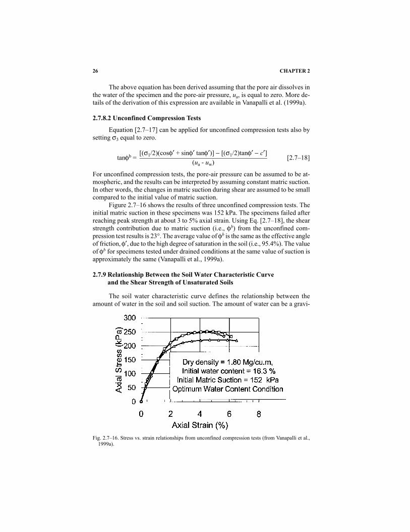
Figure 2.7–16 shows the results of three unconfined compression tests. Theinitial matric suction in these specimens was 152 kPa. The specimens failed afterreaching peak strength at about 3 to 5% axial strain. Using Eq. [2.7–18], the shearstrength contribution due to matric suction (i.e., fb) from the unconfined com-pression test results is 23°. The average value of fb is the same as the effective angleof friction, f¢, due to the high degree of saturation in the soil (i.e., 95.4%). The valueof fb for specimens tested under drained conditions at the same value of suction isapproximately the same (Vanapalli et al., 1999a).
2.7.9 Relationship Between the Soil Water Characteristic Curveand the Shear Strength of Unsaturated Soils
The soil water characteristic curve defines the relationship between theamount of water in the soil and soil suction. The amount of water can be a gravi-
26 CHAPTER 2
Fig. 2.7–16. Stress vs. strain relationships from unconfined compression tests (from Vanapalli et al.,1999a).
metric water content, w, or a volumetric water content, q. The soil water charac-teristic curve can also plotted as a relationship between the degree of saturation, S,and soil suction. Experimental procedures for measuring the soil water character-istic curve in the laboratory are available in Fredlund and Rahardjo (1993). Stan-dard testing procedures as per ASTM methods for determining the soil water char-acteristic curves for coarse and fine-textured soils are summarized in MethodsD2325-68 (1981)e1 and D3152-72 (1994)e1, respectively (ASTM, 1981, 1994).
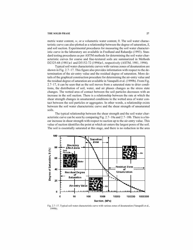
Typical soil water characteristic curves with various zones of desaturation areshown in Fig. 2.7–17. This figure also provides information with respect to the de-termination of the air-entry value and the residual degree of saturation. More de-tails of the graphical construction procedure for determining the air-entry value andthe residual degree of saturation are available in Vanapalli et al. (1999b). From Fig.2.7–17, it can be seen that as the soil moves from a saturated state to drier condi-tions, the distribution of soil, water, and air phases changes as the stress statechanges. The wetted area of contact between the soil particles decreases with anincrease in the soil suction. There is a relationship between the rate at which theshear strength changes in unsaturated conditions to the wetted area of water con-tact between the soil particles or aggregates. In other words, a relationship existsbetween the soil water characteristic curve and the shear strength of unsaturatedsoils.
The typical relationship between the shear strength and the soil water char-acteristic curve can be seen by comparing Fig. 2.7–18a and 2.7–18b. There is a lin-ear increase in shear strength with respect to suction up to the air-entry value. Thisvalue of suction identifies the point at which air enters the largest pores of the soil.The soil is essentially saturated at this stage, and there is no reduction in the area
THE SOLID PHASE 27
Fig. 2.7–17. Typical soil water characteristic curve with various zones of desaturation (Vanapalli et al.,1999b).

of water in this stage. The rate of desaturation with respect to an increase in matricsuction, that is, dS/(ua - uw), is greatest between the air-entry value and the suctioncorresponding to residual water-content conditions. The amount of water at the soilparticle (or aggregate) contacts reduces as desaturation continues (i.e., the water-menisci area in contact with the soil particles or aggregates is not continuous andstarts reducing) in this stage. There is a nonlinear increase in shear strength in thisregion.
Several equations are available in the literature to fit the soil water charac-teristic curve data for a limited range of suction (Brooks & Corey 1964; vanGenuchten, 1980). Fredlund and Xing (1994) provided an analytical basis formathematically defining the entire soil water characteristic curve. The equation ap-
28 CHAPTER 2
Fig. 2.7–18. (a) A typical soil water characteristic curve; (b) shear strength behavior of soil as it relatesto the soil water characteristic curve (from Vanapalli et al., 1996).

plies to the entire range of suctions from 0 to 1 000 000 kPa. This relationship isempirical, but is derived based on the pore-size distribution, assuming that the soilconsists of a set of interconnected pores that are randomly distributed. The equa-tion is most commonly written in terms of volumetric water content, q.
qsq = C(y) __________________ [2.7–19]â ln{[e + (y/a)n]}m êwhere q is the volumetric water content, qs is the saturated volumetric water con-tent, a is a suction related to the air-entry value of the soil, n is a soil parameter re-lated to the slope at the inflection point on the soil water characteristic curve, y issoil suction, m is a soil parameter related to the residual water content, qr is the vol-umetric water content at residual conditions, e is a natural number (2.71828...), andC(y) is a correction function that forces the soil water characteristic curve througha suction of 1 000 000 kPa and zero water content.
The correction factor forces the soil water characteristic curve through 1 000000 kPa and is defined as:
ln[1 + y/Cr)]C(y) = 1 - _________________ [2.7–20]9 ln[1 + (1000000)/Cr)] A
where Cr is the suction value corresponding to residual water content, qr.Equation [2.7–19] can be written in a normalized form by dividing both sides
of the equation by the volumetric water content at saturation:
1Q = C(y) ___________ [2.7–21]9 ln[e + (y/a)n] AThe dimensionless volumetric water content, Q, is defined as:
Q = q/qs [2.7–22]
where q is the volumetric water content, and qs is the volumetric water content ata saturation of 100%.
The degree of saturation, S, however, is also equal to the dimensionless vol-umetric water content (i.e., Q = S).
Equation [2.7–19] or [2.7–21] can be used to best-fit soil water characteris-tic curve data of any soil for the entire range of suctions. The fitting parameters (i.e.,a, n, and m values) must be determined using a nonlinear regression procedure (Fred-lund & Xing, 1994).
2.7.10 Procedure for Predicting the Shear Strength of Unsaturated Soils
Vanapalli et al. (1996) and Fredlund et al. (1996) proposed that the shearstrength of an unsaturated soil at any given value of suction be written as follows:
THE SOLID PHASE 29

t = [c¢ + (sn - ua)tanf¢] + (ua - uw)(Qktanf¢) [2.7–23]
The first part of the equation is the saturated shear strength when the pore-air pres-sure, ua, is equal to the pore-water pressure, uw. This part of the equation is a func-tion of normal stress since the shear strength parameters c¢ and f¢ are constant fora saturated soil. For a particular net normal stress, this value is a constant. The sec-ond part of the equation is the shear strength contribution due to suction, which canbe predicted using the soil water characteristic curve.
To obtain a better correlation between predictions and experimental shearstrength data, a fitting parameter such as k is useful in Eq. [2.7–23]. Vanapalli andFredlund (2000) have shown comparisons between the measured and predicted val-ues of shear strength for several statically compacted soils using Eq. [2.7–23]. Theanalyses of the results have shown that the shear strength for unsaturated soils canbe predicted with a reasonable degree of accuracy for a large suction range (i.e.,0–10 000 kPa). A relationship between the fitting parameter, k, and the plasticityindex, Ip, was also proposed based on this study (Fig. 2.7–19).
Extending the same philosophical concepts, Vanapalli et al. (1996) proposedanother equation for predicting the shear strength without using the fitting parameter,k. The equation is given below:
t = c¢ + (sn - ua)tanf¢ + (ua - uw){[tanf¢][(q - qr)/(qs - qr)]} [2.7–24]
where qr is the residual volumetric water content.The forms of Eq. [2.7–23] and [2.7–24] are consistent with the Fredlund et
al. equation (Eq. [2.7–4]) for determining the shear strength of an unsaturated soil.Figure 2.7–20 shows the soil water characteristic curves of statically com-
pacted clay-till specimens at three different initial water-content conditions repre-senting dry-of-optimum, optimum, and wet-of-optimum conditions for the entiresuction range of 1 000 000 kPa. The specimens compacted at dry-of-optimum water-content conditions desaturated at a faster rate in comparison with specimens com-pacted at higher water contents (i.e., optimum and wet-of-optimum water-contentconditions). The effective saturated shear strength parameters for specimens com-
30 CHAPTER 2
Fig. 2.7–19. The relationship between the fitting parameter k, and plasticity index, Ip (Vanapalli & Fred-lund, 2000).

pacted at these three water-content conditions were also determined. The shearstrength parameters for the specimens compacted at three different water contentsfall in a narrow range. The shear strength parameters, effective cohesion, and angleof internal friction were equal to zero and 23°, respectively.
The variation of shear strength for a suction range of 0 to 500 kPa was pre-dicted using Eq. [2.7–23] and [2.7–24]. Experimental values of shear strength forthe same suction range were also measured under consolidated drained conditionsusing direct shear test equipment described in this section. The experimental dataare shown as symbols, and the predicted values are shown as continuous lines (Fig.2.7–21). There is a good correlation between the measured and predicted values ofshear strength. More details of the soil properties and testing procedures are avail-able in Vanapalli et al. (1996).
THE SOLID PHASE 31
Fig. 2.7–21. Variation of shear strength with respect to matric suction at three different initial water con-tent conditions (Vanapalli et al., 1996).
Fig. 2.7–20. Soil water characteristic curves for specimens at three different initial water content con-ditions (from Vanapalli et al., 1996).

2.7.11 Summary
Geotechnical, agricultural, geological, hydrogeological, and geoenviron-mental engineers and soil scientists are commonly required to deal with soils thatare both in saturated and unsaturated conditions. This section provides details withrespect to theory, experimental procedures, and estimation of the shear strength ofsoils in unsaturated conditions.
2.7.12 References
American Society for Testing and Materials. 1981. Standard test method for capillary moisture rela-tionships for coarse-and medium-textured soils by pressure–plate apparatus. ASTM D2325-68(1981)e1. Annual book of ASTM Standards. ASTM, West Conshohocken, PA.
American Society for Testing and Materials. 1994. Standard test method for capillary-moisture rela-tionships for fine-textured soils by pressure-membrane apparatus. ASTM D3152-72 (1994)e1.Annual book of ASTM Standards. ASTM, West Conshohocken, PA.
American Society for Testing and Materials. 1995a. Standard test method for consolidated undrainedtriaxial compression test for cohesive soils. ASTM D4767-95. Annual book of ASTM Standards.ASTM, West Conshohocken, PA.
American Society for Testing and Materials. 1995b. Standard test method for unconsolidated, undrainedcompressive strength of cohesive soils in triaxial compression. ASTM D2850-95e1. Annual bookof ASTM Standards. ASTM, West Conshohocken, PA.
American Society for Testing and Materials. 1998a. Standard test method for direct shear test of soilsunder consolidated drained conditions. ASTM D3080-98. Annual book of ASTM Standards.ASTM, West Conshohocken, PA.
American Society for Testing and Materials. 1998b. Standard test method for unconfined compressivestrength of cohesive soil. ASTM D2166-98a. Annual book of ASTM Standards. ASTM, WestConshohocken, PA.
Bao, C., G. Bewei, and Z. Liangtong. 1998. Properties of unsaturated soils and slope stability of ex-pansive soils. Keynote Lecture, UNSAT 98. 2nd International Conference on Unsaturated Soils.Beijing, China. 27–30 Aug. 1998. China Academy of Railway Science, Beijing, China.
Bishop, A.W. 1954. The use of pore pressure coefficients in practice. Geotechnique 4:148–152.Bishop, A.W., I. Alpan, G.E. Blight, and I.B. Donald. 1960. Factors controlling the shear strength of
partly saturated cohesive soils. p. 503–532. In ASCE Research Conference on Shear Strengthof Cohesive Soils. University of Colorado, Boulder, CO.
Bishop, A.W., and I.B. Donald. 1961. The experimental study of partly saturated soil in the triaxial ap-paratus. p. 13–21. In Proceedings 5th International Conference on Soil Mech. and Found. Eng.Paris, France. Vol. 1.
Bishop, A.W., and D.J. Henkel. 1962. The measurement of soil properties and the triaxial test, 2nd ed.Edward Arnold, London, England.
Bishop, A.W., and R.E. Gibson. 1963. The influence of the provisions for boundary drainage onstrength and consolidation characteristics of soils measured in the triaxial apparatus. Labora-tory Shear Testing of Soils. American Society for Testing and Materials (ASTM), STP No.361:435–458. ASTM, Philadelphia, PA.
Brooks, R.H., and A.T. Corey. 1964. Hydraulic properties of porous media. Hydrology Paper, no. 3. Col-orado State University, Fort Collins, CO.
Chantawarangul, K. 1983. Comparative study of different procedures to evaluate effective stressstrength parameters for partially saturated soils. M.Sc. thesis. Asia Inst. of Tech., Bangkok, Thai-land.
Donald, I.B. 1963. Effective stress parameters in unsaturated soils. p. 41–46. In Proceedings 4th Aus-tralia–New Zealand Conf. Soil Mech. Found. Eng. Adelaide, South Australia.
Escario, V. 1980. Suction controlled penetration and shear tests. p. 781–787. In Proceedings 4th Inter-national Conference Expansive Soils. Denver, CO. Vol. 2. ASCE, Reston, VA.
Escario, V., and J. Sàez. 1986. The shear strength of partly saturated soils. Géotechnique 36:453–456.Escario, V., and J.F.T. Juca. 1989. Strength and deformation partly saturated soils. p. 43–46. In Pro-
ceedings of the 12th International Conf. on Soil Mech. and Found. Eng. Rio de Janeiro, Brazil.Vol. 3.
32 CHAPTER 2

Fredlund, D.G., N.R., Morgenstern, and R.A. Widger. 1978. Shear strength of unsaturated soils. Can.Geotech. J. 15:313–321.
Fredlund, D.G., and A. Xing. 1994. Equations for the soil-water characteristic curve. Can. Geotech. J.31:521–532.
Fredlund, D.G., and H. Rahardjo. 1993. Soil mechanics for unsaturated soils. John Wiley and Sons, NewYork, NY.
Fredlund, D.G., A. Xing, M.D. Fredlund, and S.L. Barbour. 1996. The relationship of the unsaturatedsoil shear strength to the soil-water characteristic curve. Can. Geotech. J. 33:440–448.
Gan, J.K.M. 1986. Direct shear strength of unsaturated soils. M.Sc. thesis. Department of Civil Engi-neering, University of Saskatchewan, Saskatoon, SK, Canada.
Gan, J.K.M., D.G. Fredlund, and H. Rahardjo. 1988. Determination of the shear strength parameters ofan unsaturated soil using the direct shear test. Can. Geotech. J. 25:500–510.
Gibson, R.E., and D.J. Henkel. 1954. Influence of duration of tests at constant rate of strain on mea-sured ‘drain’ strength. Géotechnique 4:6–15.
Green, R.E., and J.C Corey. 1971. Calculation of hydraulic conductivity: A further evaluation of somepredictive methods. Soil Sci. Soc. Am. Proc. 35:3–8.
Hasan, J.V., and D.G. Fredlund. 1980. Pore pressure parameters for unsaturated soils. Can. Geotech. J.17:395–404.
Hilf, J.W. 1956. An investigation of pore-water pressure in compacted cohesive soils. Ph.D. diss. Tech.Memo. no. 654. U.S. Dep. of the Interior Bureau of Reclamation, Washington, DC.
Ho, D.Y.F., and D.G. Fredlund. 1982a. Strain rates for unsaturated soil shear strength testing. In Pro-ceedings 7th South-east Asian Geotechnical Conference. Hong Kong.
Ho, D.Y.F., and D.G. Fredlund. 1982b. A multi-stage triaxial test for unsaturated soils. American So-ciety for Testing and Materials (ASTM) Geotech. Test. J. 5(1/2):18–25.
Holtz, W.G., and W.G Kovacs. 1981. An introduction to geotechnical engineering. Prentice-Hall, En-gelwood Cliffs, NJ.
Lambe, T.W. 1951. Soil testing for engineers. Wiley Publications, New York, NY.Oberg, A., and G. Sallfours. 1997. Determination of shear strength parameters of unsaturated silts and
sands based on the water retention curve. American Society for Testing and Materials (ASTM)Geotech. Test. J. 20:40–48.
Satija, B.S., and S.K. Gulhati. 1979. Strain rate for shearing testing of unsaturated soil. p. 83–86. In Pro-ceedings 6th Asian Regional Conference Soil Mech. and Found. Eng. Singapore.
Skempton, A.W. 1948. The fu = 0 analysis for stability and its theoretical basis. p. 72–77. In SecondInternational Conference of Soil Mechanics and Foundation Engineering. Vol. 1.
Skempton, A.W. 1954. The pore pressure coefficients A and B. Geotechnique 4:143–147.Vanapalli, S.K., and Fredlund, D.G. 2000. Comparison of empirical procedures to predict the shear
strength of unsaturated soils uses the soil-water characteristic curve, Geo-Denver 2000. Amer-ican Society of Civil Engineers, Special Publication. No. 99, pp. 195–209.
Vanapalli, S.K., D.G Fredlund, D.E. Pufahl, and A.W. Clifton. 1996. Model for the prediction of shearstrength with respect to soil suction. Can. Geotech. J. 33:379–392.
Vanapalli, S.K., D.E. Pufahl, and D.G. Fredlund. 1999a. Interpretation of the shear strength of unsatu-rated soils in undrained loading conditions. p. 643–650. 52nd Canadian Geotechnical Confer-ence. Regina. 25–27 Oct. 1999.
Vanapalli, S.K., D.G., Fredlund, and D.E. Pufahl. 1999b. Influence of soil structure and stress historyon the soil-water characteristics of a compacted till. Géotechnique 49:143–159.
van Genuchten, M.Th. 1980. A closed-form equation predicting the hydraulic conductivity of unsatu-rated soils. Soil Sci. Soc. Am. J. 44:892–898.
THE SOLID PHASE 33