27 II/28 II - Fluke Corporationassets.fluke.com/manuals/2xii____gseng0000.pdf · Lifetime Limited...
26
PN 3368142 September 2009 © 2009 Fluke Corporation. All rights reserved. Printed in USA. Specifications are subject to change without notice. All product names are trademarks of their respective companies. 27 II/28 II Digital Multimeters Getting Started Manual Specifications
Transcript of 27 II/28 II - Fluke Corporationassets.fluke.com/manuals/2xii____gseng0000.pdf · Lifetime Limited...
PN 3368142 September 2009 © 2009 Fluke Corporation. All rights reserved. Printed in USA. Specifications are subject to change without notice. All product names are trademarks of their respective companies.
27 II/28 II Digital Multimeters
Getting Started Manual
Specifications

Lifetime Limited Warranty Each Fluke 20, 70, 80, 170, 180 and 280 Series DMM will be free from defects in material and workmanship for its lifetime. As used herein, “lifetime” is defined as seven years after Fluke discontinues manufacturing the product, but the warranty period shall be at least ten years from the date of purchase. This warranty does not cover fuses, disposable batteries, damage from neglect, misuse, contamination, alteration, accident or abnormal conditions of operation or handling, including failures caused by use outside of the product’s specifications, or normal wear and tear of mechanical components. This warranty covers the original purchaser only and is not transferable. For ten years from the date of purchase, this warranty also covers the LCD. Thereafter, for the lifetime of the DMM, Fluke will replace the LCD for a fee based on then current component acquisition costs. To establish original ownership and prove date of purchase, please complete and return the registration card accompanying the product, or register your product on http://www.fluke.com. Fluke will, at its option, repair at no charge, replace or refund the purchase price of a defective product purchased through a Fluke authorized sales outlet and at the applicable international price. Fluke reserves the right to charge for importation costs of repair/replacement parts if the product purchased in one country is sent for repair elsewhere. If the product is defective, contact your nearest Fluke authorized service center to obtain return authorization information, then send the product to that service center, with a description of the difficulty, postage and insurance prepaid (FOB Destination). Fluke assumes no risk for damage in transit. Fluke will pay return transportation for product repaired or replaced in-warranty. Before making any non-warranty repair, Fluke will estimate cost and obtain authorization, then invoice you for repair and return transportation. THIS WARRANTY IS YOUR ONLY REMEDY. NO OTHER WARRANTIES, SUCH AS FITNESS FOR A PARTICULAR PURPOSE, ARE EXPRESSED OR IMPLIED. FLUKE SHALL NOT BE LIABLE FOR ANY SPECIAL, INDIRECT, INCIDENTAL OR CONSEQUENTIAL DAMAGES OR LOSSES, INCLUDING LOSS OF DATA, ARISING FROM ANY CAUSE OR THEORY. AUTHORIZED RESELLERS ARE NOT AUTHORIZED TO EXTEND ANY DIFFERENT WARRANTY ON FLUKE’S BEHALF. Since some states do not allow the exclusion or limitation of an implied warranty or of incidental or consequential damages, this limitation of liability may not apply to you. If any provision of this warranty is held invalid or unenforceable by a court or other decision-maker of competent jurisdiction, such holding will not affect the validity or enforceability of any other provision.
Fluke Corporation P.O. Box 9090 Everett, WA 98206-9090 U.S.A.
Fluke Europe B.V. P.O. Box 1186 5602 BD Eindhoven The Netherlands
5/07
i
Table of Contents
Title Page
Introduction .................................................................................................................... 1 How to Contact Fluke..................................................................................................... 1 Safety Information .......................................................................................................... 2 Features ......................................................................................................................... 6
Automatic Power-Off ................................................................................................. 13 Input Alert™ Feature ................................................................................................. 13 Power-Up Options ..................................................................................................... 13
Maintenance................................................................................................................... 15 General Maintenance ................................................................................................ 15 Fuse Test .................................................................................................................. 15 How to Replace the Batteries .................................................................................... 16 How to Replace the Fuses ........................................................................................ 17
Service and Parts ........................................................................................................... 17

27 II/28 II Getting Started Manual
ii
iii
List of Tables
Table Title Page
1. Symbols................................................................................................................................. 5 2. Inputs .................................................................................................................................... 6 3. Rotary Switch Positions......................................................................................................... 7 4. Pushbuttons .......................................................................................................................... 8 5. Display Features ................................................................................................................... 11 6. Power-Up Options ................................................................................................................. 14 7. Replacement Parts................................................................................................................ 19 8. Accessories ........................................................................................................................... 21

27 II/28 II Getting Started Manual
iv

v
List of Figures
Figure Title Page
1. Display Features ................................................................................................................... 11 2. Current Fuse Test ................................................................................................................. 16 3. Battery and Fuse Replacement ............................................................................................. 18 4. Replacement Parts................................................................................................................ 20

27 II/28 II Getting Started Manual
vi

1
Introduction XW Warning
Read “Safety Information” before using the Meter.
Except where noted, the descriptions and instructions in this manual refer to both Series II Models 27 and 28 multimeters (hereafter referred to as “the Meter”). Model 28 II appears in all illustrations.
The Model 27 II is an average-responding Digital Multimeter while the 28 II is a True-rms Digital Multimeter. In addition the 28 II measures temperature using a type-K thermocouple.
This manual covers information for turning on the Meter, understanding its controls, and basic maintenance. For complete operational instructions, refer to the 27 II/28 II Users Manual contained on the accompanying CD.
How to Contact Fluke To contact Fluke, call one of the following telephone numbers:
Technical Support USA: 1-800-44-FLUKE (1-800-443-5853)
Calibration/Repair USA: 1-888-99-FLUKE (1-888-993-5853)
Canada: 1-800-36-FLUKE (1-800-363-5853)
Europe: +31 402-675-200
Japan: +81-3-3434-0181
Singapore: +65-738-5655
Anywhere in the world: +1-425-446-5500
Or, visit Fluke's website at www.fluke.com.
To register your product, visit http://register.fluke.com.
To view, print, or download the latest manual supplement, visit http://us.fluke.com/usen/support/manuals.
27 II/28 II Getting Started Manual
2
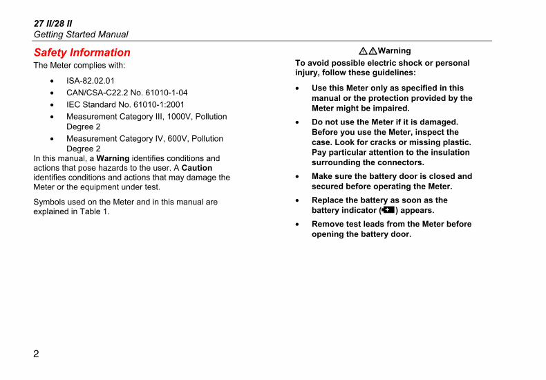
Safety Information The Meter complies with:
• ISA-82.02.01 • CAN/CSA-C22.2 No. 61010-1-04 • IEC Standard No. 61010-1:2001 • Measurement Category III, 1000V, Pollution
Degree 2 • Measurement Category IV, 600V, Pollution
Degree 2 In this manual, a Warning identifies conditions and actions that pose hazards to the user. A Caution identifies conditions and actions that may damage the Meter or the equipment under test.
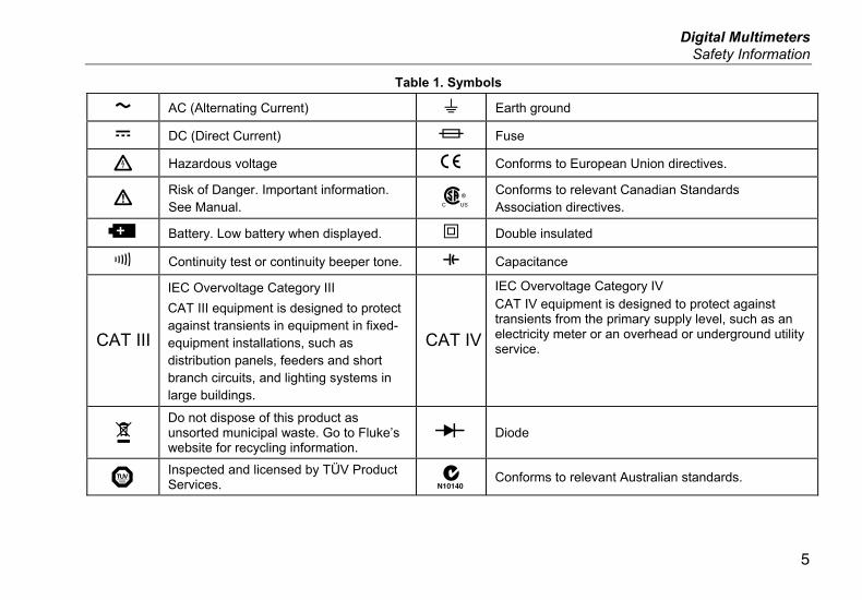
Symbols used on the Meter and in this manual are explained in Table 1.
XWWarning To avoid possible electric shock or personal injury, follow these guidelines:
• Use this Meter only as specified in this manual or the protection provided by the Meter might be impaired.
• Do not use the Meter if it is damaged. Before you use the Meter, inspect the case. Look for cracks or missing plastic. Pay particular attention to the insulation surrounding the connectors.
• Make sure the battery door is closed and secured before operating the Meter.
• Replace the battery as soon as the battery indicator (b) appears.
• Remove test leads from the Meter before opening the battery door.

Digital Multimeters Safety Information
3
• Inspect the test leads for damaged insulation or exposed metal. Check the test leads for continuity. Replace damaged test leads before you use the Meter.
• Do not apply more than the rated voltage, as marked on the Meter, between the terminals or between any terminal and earth ground.
• Never operate the Meter with the cover removed or the case open.
• Use caution when working with voltages above 30 V ac rms, 42 V ac peak, or 60 V dc. These voltages pose a shock hazard.
• Use only the replacement fuses specified by the manual.
• Use the proper terminals, function, and range for measurements.
• Avoid working alone. • When measuring current, turn off circuit
power before connecting the Meter in the circuit. Remember to place the Meter in series with the circuit.
• When making electrical connections, connect the common test lead before connecting the live test lead; when disconnecting, disconnect the live test lead before disconnecting the common test lead.
• Do not use the Meter if it operates abnormally. Protection may be impaired. When in doubt, have the Meter serviced.
• Do not use the Meter around explosive gas, vapor or in damp or wet environments.
• Use only three 1.5-V AA batteries, properly installed in the Meter case, to power the Meter.

27 II/28 II Getting Started Manual
4
• When servicing the Meter, use only specified replacement parts.
• When using probes, keep fingers behind the finger guards on the probes.
• Do not use the Low-Pass Filter to verify the presence of hazardous voltages. Voltages greater than what is indicated may be present. First, make a voltage measurement without the filter to detect the possible presence of hazardous voltage. Then add the filter.
WCaution To avoid possible damage to the Meter or to the equipment under test, follow these guidelines:
• Disconnect circuit power and discharge all high-voltage capacitors before testing resistance, continuity, diodes, or capacitance.
• Use the proper terminals, function, and range for all measurements.
• Before measuring current, check the Meter’s fuses. (See “Fuse Test”.)
Digital Multimeters Safety Information
5
Table 1. Symbols
B AC (Alternating Current) J Earth ground
F DC (Direct Current) I Fuse
X Hazardous voltage P Conforms to European Union directives.
W Risk of Danger. Important information. See Manual.
) Conforms to relevant Canadian Standards Association directives.
b Battery. Low battery when displayed. T Double insulated
R Continuity test or continuity beeper tone. E Capacitance
CAT III
IEC Overvoltage Category III CAT III equipment is designed to protect against transients in equipment in fixed-equipment installations, such as distribution panels, feeders and short branch circuits, and lighting systems in large buildings.
CAT IV
IEC Overvoltage Category IV CAT IV equipment is designed to protect against transients from the primary supply level, such as an electricity meter or an overhead or underground utility service.
~ Do not dispose of this product as unsorted municipal waste. Go to Fluke’s website for recycling information.
O Diode
® Inspected and licensed by TÜV Product Services. ; Conforms to relevant Australian standards.

27 II/28 II Getting Started Manual
6
Features Tables 2 through 5 briefly describe the features of the Meter.
Table 2. Inputs
gaq112.eps
Terminal Description
A Input for 0 A to 10.00 A current (10 - 20 A overload for 30 seconds maximum), current frequency, and duty cycle measurements.
k Input for 0 μA to 400 mA current measurements (600 mA for 18 hrs) and current frequency and duty cycle.
COM Return terminal for all measurements.
I Input for voltage, continuity, resistance, diode, capacitance, frequency, temperature (28 II only), and duty cycle measurements.
Digital Multimeters Features
7
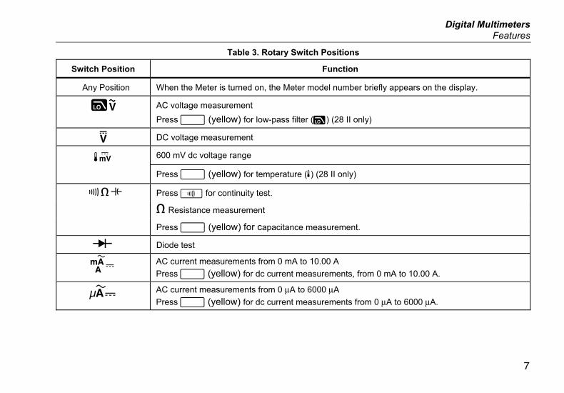
Table 3. Rotary Switch Positions
Switch Position Function
Any Position When the Meter is turned on, the Meter model number briefly appears on the display.
KK AC voltage measurement
Press A (yellow) for low-pass filter (K) (28 II only)
L DC voltage measurement
600 mV dc voltage range M Press A (yellow) for temperature (d) (28 II only)
N Press E for continuity test.
e Resistance measurement
Press A (yellow) for capacitance measurement.
O Diode test
P AC current measurements from 0 mA to 10.00 A Press A (yellow) for dc current measurements, from 0 mA to 10.00 A.
Q AC current measurements from 0 μA to 6000 μA Press A (yellow) for dc current measurements from 0 μA to 6000 μA.
27 II/28 II Getting Started Manual
8
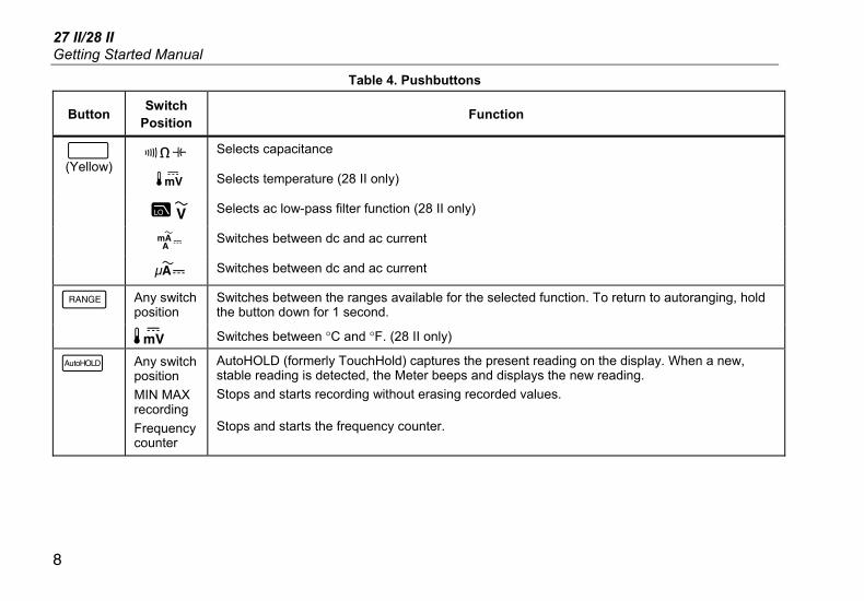
Table 4. Pushbuttons
Button Switch Position Function
N Selects capacitance
M Selects temperature (28 II only)
J Selects ac low-pass filter function (28 II only)
P Switches between dc and ac current
A (Yellow)
Q Switches between dc and ac current
Any switch position
Switches between the ranges available for the selected function. To return to autoranging, hold the button down for 1 second.
C
M Switches between °C and °F. (28 II only)
D Any switch position MIN MAX recording Frequency counter
AutoHOLD (formerly TouchHold) captures the present reading on the display. When a new, stable reading is detected, the Meter beeps and displays the new reading. Stops and starts recording without erasing recorded values.
Stops and starts the frequency counter.

Digital Multimeters Features
9
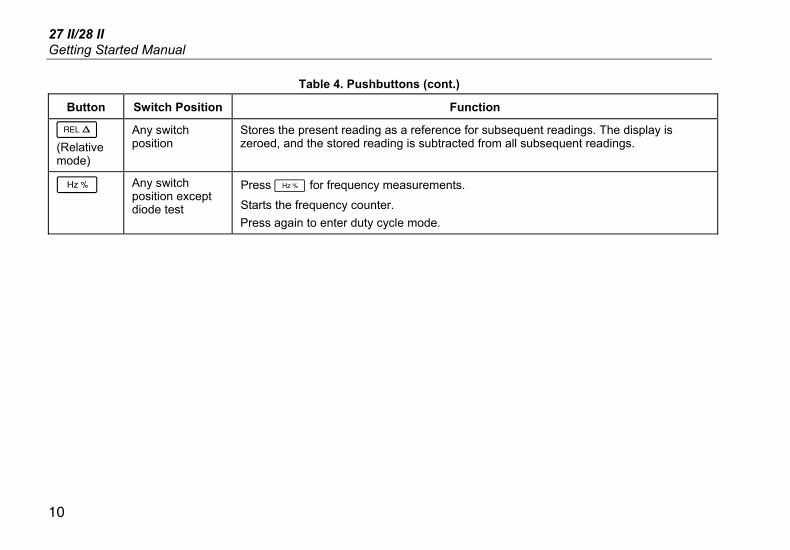
Table 4. Pushbuttons (cont.)
Button Switch Position Function
E Continuity N MIN MAX recording Hz, Duty Cycle
Turns the continuity beeper on and off
Switches between Peak (250 μs) and Normal (100 ms) response times. (28 II only)
Toggles the meter to trigger on positive or negative slope.
H Any switch position
Turns the button backlight and display backlight on, makes them brighter, and turns them off.
For Model 28 II, hold H down for one second to enter the HiRes digit mode. The “HiRes” icon appears on the display. To return to the 3-1/2 digit mode, hold H down for one second. HiRes=19,999
B Any switch position
Starts recording of minimum and maximum values. Steps the display through MAX, MIN, AVG (average), and present readings. Cancels MIN MAX (hold for 1 second)
27 II/28 II Getting Started Manual
10
Table 4. Pushbuttons (cont.)
Button Switch Position Function
F (Relative mode)
Any switch position
Stores the present reading as a reference for subsequent readings. The display is zeroed, and the stored reading is subtracted from all subsequent readings.
G Any switch position except diode test
Press G for frequency measurements.
Starts the frequency counter. Press again to enter duty cycle mode.
Digital Multimeters Features
11
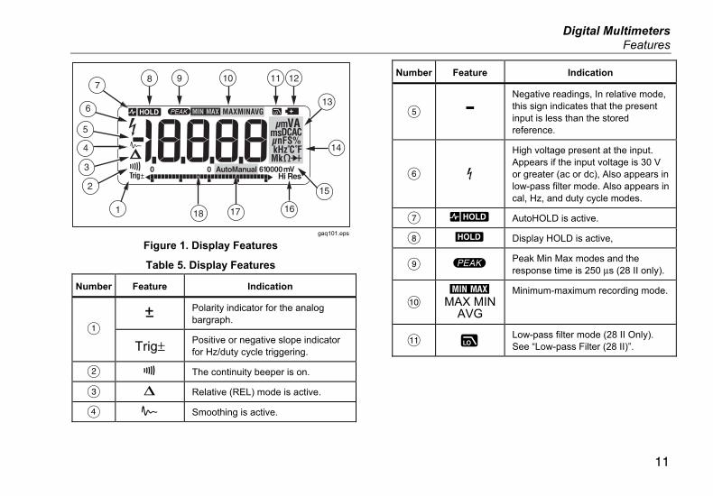
gaq101.eps
Figure 1. Display Features
Table 5. Display Features
Number Feature Indication
Y Polarity indicator for the analog bargraph.
A Trig± Positive or negative slope indicator
for Hz/duty cycle triggering.
B X The continuity beeper is on.
C W Relative (REL) mode is active.
D a Smoothing is active.
Number Feature Indication
E - Negative readings, In relative mode, this sign indicates that the present input is less than the stored reference.
F Z
High voltage present at the input. Appears if the input voltage is 30 V or greater (ac or dc), Also appears in low-pass filter mode. Also appears in cal, Hz, and duty cycle modes.
G RS AutoHOLD is active.
H S Display HOLD is active,
I p Peak Min Max modes and the response time is 250 μs (28 II only).
J €
MAX MIN AVG
Minimum-maximum recording mode.
K K Low-pass filter mode (28 II Only). See “Low-pass Filter (28 II)”.
27 II/28 II Getting Started Manual
12
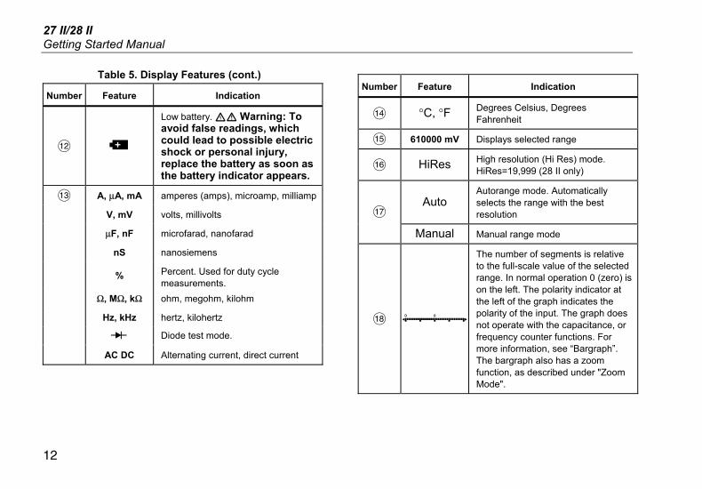
Table 5. Display Features (cont.)
Number Feature Indication
L b
Low battery. XW Warning: To avoid false readings, which could lead to possible electric shock or personal injury, replace the battery as soon as the battery indicator appears.
M A, μA, mA amperes (amps), microamp, milliamp
V, mV volts, millivolts
μF, nF microfarad, nanofarad
nS nanosiemens
% Percent. Used for duty cycle measurements.
Ω, MΩ, kΩ ohm, megohm, kilohm
Hz, kHz hertz, kilohertz
O Diode test mode.
AC DC Alternating current, direct current
Number Feature Indication
N °C, °F Degrees Celsius, Degrees Fahrenheit
O 610000 mV Displays selected range
P HiRes High resolution (Hi Res) mode. HiRes=19,999 (28 II only)
Auto Autorange mode. Automatically selects the range with the best resolution Q
Manual Manual range mode
R
The number of segments is relative to the full-scale value of the selected range. In normal operation 0 (zero) is on the left. The polarity indicator at the left of the graph indicates the polarity of the input. The graph does not operate with the capacitance, or frequency counter functions. For more information, see “Bargraph”. The bargraph also has a zoom function, as described under "Zoom Mode".

Digital Multimeters Features
13
Table 5. Display Features (cont.)
Number Feature Indication
-- 0L Overload condition is detected.
Error Messages
bAtt Replace the battery immediately.
di'c In the capacitance function, too much electrical charge is present on the capacitor being tested.
CAL Err Invalid calibration data. Calibrate Meter.
EEPr Err Invalid EEPROM data. Have the Meter serviced.
0PEn Open thermocouple detected.
F2_ Invalid model. Have the Meter serviced.
LEAd W Test lead alert. Displayed when the test leads are in the A or mA/μA terminal and the selected rotary switch position does not correspond to the terminal being used.
Automatic Power-Off The Meter automatically turns off if you do not turn the rotary switch or press a button for 30 minutes. If MIN MAX Recording is enabled, the Meter will not power off. Refer to Table 6 to disable automatic power-off.
Input Alert™ Feature If a test lead is plugged into the mA/μA or A terminal, but the rotary switch is not set to the correct current position, the beeper warns you by making a chirping sound and the display flashes “LEAd”, This warning is intended to stop you from attempting to measure voltage, continuity, resistance, capacitance, or diode values with the leads are plugged into a current terminal.
W Caution Placing the probes across (in parallel with) a powered circuit when a lead is plugged into a current terminal can damage the circuit you are testing and blow the Meter’s fuse. This can happen because the resistance through the Meter’s current terminals is very low, so the Meter acts like a short circuit.
Power-Up Options Holding a button down while turning the Meter on activates a power-up option. Table 6 describes power-up options.

27 II/28 II Getting Started Manual
14
Table 6. Power-Up Options
Button Power-Up Option
A (Yellow)
Disables automatic power-off feature (Meter normally powers off in 30 minutes). The Meter reads “PoFF” until A is released.
B Enables the Meter’s calibration mode and prompts for a password. The Meter reads “CAL” and enters calibration mode. See 27 II/28 II Calibration Information.
C Enables the Meter’s smoothing feature. The Meter reads “'---” until C is released.
D Turns on all LCD segments.
E Disables the beeper for all functions. The Meter reads “bEEP” until E is released.
H Disables auto backlight off (backlight normally disables after 2 minutes). The Meter reads “LoFF” until H is released.
F (Relative mode)
Enables zoom mode for the bargraph. The Meter reads “2rEL” until F is released.
G Enables the Meter’s high impedance mode when the mV dc function is used. The Meter reads “Hi2” until G is released. (28 II only)
Digital Multimeters Maintenance
15
Maintenance XWWarning
To avoid possible electric shock or personal injury, repairs or servicing not covered in this manual should be performed only by qualified personnel as described in the 27 II/28 II Calibration Information.
General Maintenance Periodically wipe the case with a damp cloth and mild detergent. Do not use abrasives or solvents.
Dirt or moisture in the terminals can affect readings and can falsely activate the Input Alert feature. Clean the terminals as follows:
1. Turn the Meter off and remove all test leads.
2. Shake out any dirt that may be in the terminals.
3. Soak a clean swab with mild detergent and water. Work the swab around in each terminal. Dry each terminal using canned air to force the water and detergent out of the terminals.
Fuse Test As shown in Figure 2, with the Meter in the N function, insert a test lead into the w jack and place the probe tip on the other end of the test lead against the metal of the current input jack. If “LEAd” appears in the display, the probe tip has been inserted too far into the amps input jack. Back the lead out a bit until the message disappears and either OL or a resistance reading appears in the display. The resistance value should be as shown in Figure 2. If the tests give readings other than those shown, have the Meter serviced.
XWWarning To avoid electrical shock or personal injury, remove the test leads and any input signals before replacing the battery or fuses. To prevent damage or injury, install ONLY specified replacement fuses with the amperage, voltage, and speed ratings shown in Table 7.

27 II/28 II Getting Started Manual
16
Touch top halfof input contacts
Good F2 fuse: 00.0 Ω to 00.5 Ω
Replace fuse: OL
Good F1 fuse: 0.995 kΩ to 1.005 kΩ
Replace fuse: OL
gaq105.eps
Figure 2. Current Fuse Test
How to Replace the Batteries Replace the batteries with three AA batteries (NEDA 15A IEC LR6).
XWWarning To avoid false readings, which could lead to possible electric shock or personal injury, replace the battery as soon as the battery indicator (b) appears. If the display shows “batt” the Meter will not function until the battery is replaced.
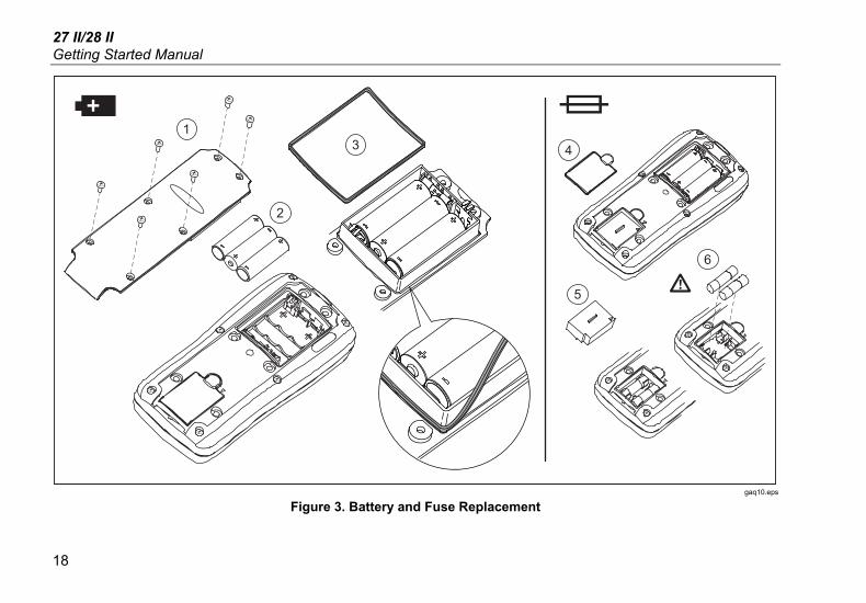
Replace the battery as follows, refer to Figure 3:
1. Turn the rotary switch to OFF and remove the test leads from the terminals.
2. Remove the six Phillips-head screws from the case bottom and remove the battery door (A).
Note While lifting the battery door, ensure the rubber gasket stays attached to the battery compartment barrier.
3. Remove the three batteries and replace all three with AA Alkaline batteries (B).
Digital Multimeters Service and Parts
17
4. Ensure the battery compartment gasket (C) is properly installed around the outside edge of the battery compartment barrier.
5. Replace the battery door by aligning the battery compartment barrier with battery compartment.
6. Secure the door with the six Phillips-head screws.
How to Replace the Fuses Referring to Figure 3, examine or replace the Meter's fuses as follows:
1. Turn the rotary switch to OFF and remove the test leads from the terminals
2. Refer to step 2 under the How to Replace the Batteries section above to remove the battery door.
3. Remove the fuse compartment seal (D) from the fuse compartment.
4. Gently lift out the fuse compartment door (E) from the fuse compartment.
5. Remove the fuse by gently prying one end loose, then sliding the fuse out of its bracket (F).
6. Install ONLY specified replacement fuses with the amperage, voltage, and speed ratings shown in Table 7. The 440-mA fuse is shorter than the 10-A fuse. For correct placement of each fuse, note the marking on the printed circuit board under each fuse.
7. Replace the fuse compartment door by aligning the arrow on the fuse door with the arrow on the case bottom and lowering the door into the fuse compartment.
8. Replace the fuse compartment seal by aligning the tab on the seal with the outline on the case bottom. Ensure the seal (D) is properly seated.
9. Refer to steps four through six under the Replacing the Batteries section above to reinstall the battery door.
Service and Parts If the Meter fails, check the battery and fuses. Review this manual to verify proper use of the Meter.
Replacement parts and accessories are shown in Table 7 and Figure 4.
To order parts and accessories, refer to “How to Contact Fluke”.
27 II/28 II Getting Started Manual
18
14
5
6
2
3
gaq10.eps
Figure 3. Battery and Fuse Replacement