![*URZLQJLQ*UDFH :LVGRP...2019/02/02 · Reflections from Fr. David:KDWDZHHNZHKDYHEHHQWKURXJK0RUHVQRZWKDQZDV H[SHFWHG GD\V RI GDQJHURXV IUHH]LQJ WHPSHUDWXUHV VOLSSHU\ URDGV FORVHG VFKRROV](https://static.fdocuments.in/doc/165x107/5e98715228dbe2753d4c149b/urzlqjlqudfh-lvgrp-20190202-reflections-from-fr-davidkdwdzhhnzhkdyhehhqwkurxjk0ruhvqrzwkdqzdv.jpg)
'2&.(7 12 3 86 *DUGHOOD *UDFH 3 $ 81,7(' 67$7(6 3$7(17 $1...
89
DOCKET NO.: P50182US00 Filed By: Greg H. Gardella, Reg. No. 46,045 Gardella Grace P.A. 455 Massachusetts Ave. NW, Suite 507 Washington, DC 20001 Tel: (703) 740-4540 Email: [email protected] UNITED STATES PATENT AND TRADEMARK OFFICE ____________ BEFORE THE PATENT TRIAL AND APPEAL BOARD ____________ 10X GENOMICS, INC. Petitioner, v. BIO-RAD LABORATORIES, INC. Patent Owner. ____________ IPR2018-00300 U.S. Patent No. 9,216,392 ____________ PETITION FOR INTER PARTES REVIEW
-
Upload
nguyentruc -
Category
Documents
-
view
215 -
download
0
Transcript of '2&.(7 12 3 86 *DUGHOOD *UDFH 3 $ 81,7(' 67$7(6 3$7(17 $1...

DOCKET NO.: P50182US00 Filed By: Greg H. Gardella, Reg. No. 46,045 Gardella Grace P.A. 455 Massachusetts Ave. NW, Suite 507 Washington, DC 20001
Tel: (703) 740-4540 Email: [email protected]
UNITED STATES PATENT AND TRADEMARK OFFICE
____________
BEFORE THE PATENT TRIAL AND APPEAL BOARD
____________
10X GENOMICS, INC.
Petitioner,
v.
BIO-RAD LABORATORIES, INC.
Patent Owner.
____________
IPR2018-00300
U.S. Patent No. 9,216,392
____________
PETITION FOR INTER PARTES REVIEW

i
TABLE OF CONTENTS
TABLE OF EXHIBITS ........................................................................................... iv
I. INTRODUCTION ............................................................................................. 1
II. MANDATORY NOTICES ............................................................................... 1
A. Real Party-in-Interest ........................................................................... 1 B. Related Matters .................................................................................... 1 C. Designation of Counsel ........................................................................ 2 D. Service Information ............................................................................. 2 E. Fees ...................................................................................................... 2
III. CERTIFICATION OF GROUNDS FOR STANDING .................................... 3
IV. OVERVIEW OF CHALLENGE AND RELIEF REQUESTED ...................... 3
A. Grounds for Challenge ......................................................................... 3 B. Prior Art Patents and Printed Publications Relied Upon ..................... 3
1. U.S. Published Application 2010/0184928 A1 to Kumacheva ........ 4 2. U.S. Published Application 2005/0266582 A1 to Modlin et al........ 5 3. Chien et al., Multiport flow-control system for lab-on-a-chip
microfluidic devices, Fresenius J Anal Chem (2001) 371 :106–111 ........................................................................................................... 5
4. Beer et al., On-Chip, Real-Time, Single-Copy Polymerase Chain Reaction in Picoliter Droplets, Anal. Chem. 2007, 79, 8471-8475 .. 6
5. U.S. Patent 6,176,962 to Soane et al. ............................................... 7 6. U.S. Published Application 2008/0166720 to Hsieh et al. ............... 7
C. Relief Requested .................................................................................. 7
V. LEVEL OF ORDINARY SKILL IN THE ART ............................................... 8
VI. OVERVIEW OF THE ‘392 PATENT .............................................................. 8
A. Priority Date of the ‘392 Patent .........................................................10 B. Summary of the Prosecution History .................................................10
VII. CLAIM CONSTRUCTION ............................................................................12

ii
VIII. GROUNDS FOR FINDING THE CHALLENGED CLAIMS INVALID.....13
A. Ground 1: Claims 1, 3-4, 6, 8-17 and 19-21 Are Rendered Obvious by Kumacheva in View of Modlin ....................................................13
1. Independent Claim 1 .......................................................................15 2. Dependent Claims 3-4 ....................................................................38 3. Dependent Claim 6 .........................................................................41 4. Dependent Claim 8 .........................................................................42 5. Dependent Claim 9 .........................................................................43 6. Dependent Claims 10-11 ................................................................45 7. Dependent Claim 12 .......................................................................48 8. Dependent Claim 13 .......................................................................49 9. Dependent Claim 14 .......................................................................51 10. Dependent Claims 15 ......................................................................53 11. Dependent Claim 16 .......................................................................55 12. Dependent Claim 17 .......................................................................57 13. Dependent Claim 19 .......................................................................58 14. Dependent Claim 20 .......................................................................59 15. Dependent Claim 21 .......................................................................59
B. Ground 2: Claims 2 and 5 Are Rendered Obvious by Kumacheva in View of Modlin and Further in View of Chien .................................60
1. Dependent Claim 2 .........................................................................60 2. Dependent Claim 5 .........................................................................62
C. Ground 3: Claim 7 Is Rendered Obvious by Kumacheva in View of Modlin and Further in View of Hsieh ................................................63
D. Ground 4: Claim 18 Is Rendered Obvious by Kumacheva in View of Modlin and Further in View of Beer .................................................66
E. Ground 5: Claims 12-17 and 19-20 Are Rendered Obvious by Kumacheva in view of Modlin and Further in view of Soane ..........69
1. Dependent Claim 12 .......................................................................71 2. Dependent Claim 13 .......................................................................72 3. Dependent Claim 14 .......................................................................73 4. Dependent Claim 15 .......................................................................73 5. Dependent Claim 16 .......................................................................74 6. Dependent Claim 17 .......................................................................75 7. Dependent Claim 19 .......................................................................76 8. Dependent Claim 20 .......................................................................77

iii
IX. SECONDARY CONSIDERATIONS OF NONOBVIOUSNESS CANNOT OVERCOME THE OBVIOUSNESS GROUNDS .........................................77
X. CONCLUSION ...............................................................................................78

iv
TABLE OF EXHIBITS
1001 U.S. Patent No. 9,216,392 to Hindson et al. (for inter partes review)
1002 Prosecution history of U.S. Patent No. 9,216,392 (U.S. Patent
Application No. 12/962,507)
1003 Declaration of Dr. Khushroo Gandhi
1004 U.S. Published Application 2010/0184928 A1 to Kumacheva et al.
1005 U.S. Published Application 2005/0266582 A1 to Modlin et al.
1006 Duffy, et al., Rapid Prototyping of Microfluidic Systems in
Poly(dimethylsiloxane), Anal. Chem., 70:4974-84 (1998)
1007 Chien and Parce, Multiport flow-control system for lab-on-a-chip
microfluidic devices, J. Anal. Chem., 371-106-11 (2001)
1008 U.S. Published Application 2009/0269248 to Falb, et al.
1009 U.S. Published Application 2009/0047713 to Handique
1010 U.S. Published Application 2009/0035770 to Mathies
1011 U.S. Provisional Application 61/047,377 to Falb et al.
1012 U.S. Patent No. 6,123,798 to Gandhi et al.
1013 Publication information for Anna, et al., Formation of dispersions using
“flow focusing” in microchannels, Appl. Phys. Lett., 82(3):364-66
(2003)
1014 U.S. Published Application 2002/0058332 to Quake et al.

v
1015 U.S. Published Application 2004/0068019 to Higuchi, et al.
1016 Anna, et al., Formation of dispersions using “flow focusing” in
microchannels, Appl. Phys. Lett., 82(3):364-66 (2003)
1017 U.S. Provisional Application 60/924,921 to Kumacheva
1018 U.S. Published Application 2008/0166720 to Hsieh, et al.
1019 U.S. Published Application 2007/0166200 to Zhou, et al.
1020 U.S. Published Application 2008/0038810 to Pollack et al.
1021 U.S. Published Application 2010/0022680 to Karnik, et al.
1022 U.S. Published Application 2009/0012187 to Chu, et al.
1023 Galambos, et al., Precision Alignment Packaging for Microsystems with
Multiple Fluid Connections, Proceedings of 2001 ASME: International
Mechanical Engineering Conference and Exposition, November 11-16,
2001. p. 1-8
1024 Publication information for Nisisako and Torii, Microfluidic large-scale
integration on a chip for mass production of monodisperse droplets and
particles, Lab on a Chip, 8:287-93 (2008)
1025 Li and Li, Microfluidic Lab-on-a-Chip (Book Chapter), p. 581-679
(2005)
1026 Whitesides and Strook, Flexible Methods for Microfluidics, Physics
Today, June 2001: 42-48

vi
1027 Complainants’ Ground Rule 4 Disclosures, Certain Microfluidic Devices,
USITC Inv. No. 337-TA-1068, filed November 17, 2017
1028 U.S. Patent No 6,176,962 to Soane
1029 U.S. Published Application 2008/0056948 A1 to Dale and Knight
1030 Publication information for Kawai, et al., Mass-Production System of
Nearly Monodisperse Diameter Gel Particles Using Droplets formation
in a Microchannel, Micro Total Analysis Systems, Micro Total Analysis
Systems, 1:368-70 (2002)
1031 Nisisako and Torii, Microfluidic large-scale integration on a chip for
mass production of monodisperse droplets and particles, Lab on a Chip,
8:287-93 (2008)
1032 Publication information for Duffy, et al., Rapid Prototyping of
Microfluidic Systems in Poly(dimethylsiloxane), Anal. Chem., 70:4974-
84 (1998)
1033 Bernouilli Pressure Lowering, http://hyperphysics p. 1-4
1034 Beer et al., On-Chip, Real-Time, Single-Copy Polymerase Chain
Reaction in Picoliter Droplets, Anal. Chem. 2007, 79, 8471-8475
1035 Publication information for Chien and Parce, Multiport flow-control
system for lab-on-a-chip microfluidic devices, J. Anal. Chem., 371-106-
11 (2001)

vii
1036 Definition of Gasket, Merriam-Webster
1037 Kawai, et al., Mass-Production System of Nearly Monodisperse Diameter
Gel Particles Using Droplets formation in a Microchannel, Micro Total
Analysis Systems, Micro Total Analysis Systems, 1:368-70 (2002)
1038 Publication information for Beer et al., On-Chip, Real-Time, Single-Copy
Polymerase Chain Reaction in Picoliter Droplets, Anal. Chem. 2007, 79,
8471-8475
1039 U.S. Patent No. 6,915,679 to Chien et al.
1040 Publication information for Li and Li, Microfluidic Lab-on-a-Chip (Book
Chapter), p. 581-679 (2005)
1041 Becker and Gartner, Polymer microfabrication technologies for
microfluidic systems, Anal. Bioanal. Chem, 390:89-111
1042 Publication information for Becker and Gartner, Polymer
microfabrication technologies for microfluidic systems, Anal. Bioanal.
Chem, 390:89-111
1043 de Mello and Manz, Chip technology for micro-separation, BioMethods
10:129-177 (1999)
1044 U.S. Published Application No. 2004/0109793 to McNeely, et al.
1045 Curriculum Vitae of Dr. Khushroo Gandhi
1046 UK Patent Application No. 2097692 to Shaw Stewart

viii
1047 Mair, et al., Injection molded microfluidic chips featuring integrated
interconnects, Lab on a Chip, 6:1346-54 (2006)
1048 Publication information for Mair, et al., Injection molded microfluidic
chips featuring integrated interconnects, Lab on a Chip, 6:1346-54
(2006)
1049 Declaration of Ruth G. Davila
1050 U.S. Patent No. 9,126,160 to Ness et al.

1
I. INTRODUCTION
Petitioner, 10X Genomics, Inc. (“Petitioner”) respectfully requests inter
partes review (“IPR”) of claims 1-21 of U.S. Patent No. 9,216,392 (“the ’392
Patent”, Ex. 1001). For the reasons set forth below, each of the challenged claims
is invalid.
II. MANDATORY NOTICES
A. Real Party-in-Interest
10X Genomics, Inc. is the real party-in-interest.
B. Related Matters
Petitioner is contemporaneously filing two additional inter partes review
petitions challenging claims 1-21 of the ‘392 patent (IPR2018-00301 and
IPR2018-00302). The following other proceedings would affect or be affected by a
decision in this proceeding: Bio-Rad Laboratories, Inc., et al. v. 10X Genomics,
Inc., Case No. 3:17-CV-4339 (N.D. Cal.) and Re: Certain Microfluidic Devices,
Investigation Number 337-TA-1068 (ITC).

2
C. Designation of Counsel
Lead Counsel Back-up Counsel Greg H. Gardella Reg. No. 46,045 Gardella Grace P.A. 455 Massachusetts Ave. NW Suite 507 Washington, DC 20001 Tel: (703) 740-4540 Email:[email protected]
Dianna DeVore Reg. No. 42,484 Sally Brashears Reg. No. 38,087 Convergent Law Group LLP 20660 Stevens Creek Blvd Suite 381 Cupertino, CA 95014 Email: [email protected]
D. Service Information
Pursuant to 37 C.F.R. § 42.10(b), Powers of Attorney accompany this
Petition. Please address all correspondence to lead counsel. Petitioner consents to
service of all documents via the following email addresses:
[email protected], [email protected] and
E. Fees
The undersigned authorizes the PTO to charge the fee set forth in 37 C.F.R.
§ 42.15(a) for this Petition to Deposit Account No. 601484. The undersigned
authorizes payment for additional fees that may be due with this petition to be
charged to the above-referenced Deposit Account.

3
III. CERTIFICATION OF GROUNDS FOR STANDING
Petitioner certifies pursuant to Rule 42.104(a) that the patent for which
review is sought is available for inter partes review and that Petitioner is not
barred or estopped from requesting an inter partes review challenging the patent
claims on the grounds identified in this Petition.
IV. OVERVIEW OF CHALLENGE AND RELIEF REQUESTED
Pursuant to Rules 42.22(a)(1) and 42.104(b)(1)-(2), Petitioner challenges
claims 1-21 (“the challenged claims”) of the ’392 Patent and requests that each
challenged claim be canceled on the basis that the subject matter is obvious under
pre-AIA 35 U.S.C. §103(a).
A. Grounds for Challenge
This petition, together with the support exhibits including the declaration of
Khushroo Gandhi, Ph.D. (“Gandhi Declaration,” Ex. 1003), demonstrates that
there is a reasonable likelihood that at least one of the challenged claims is
unpatentable for the reasons set forth herein. 35 U.S.C. §314(a).
B. Prior Art Patents and Printed Publications Relied Upon
Petitioner relies upon the following patents and printed publications, the
majority of which were before the Examiner during ex parte prosecution.

4
1. U.S. Published Application 2010/0184928 A1 to Kumacheva
U.S. Published Application 2010/0184928 A1 to Kumacheva
(“Kumacheva,” Ex. 1004), filed on June 5, 2008 and published on July 22, 2010, is
prior art to the ʼ392 patent under 35 U.S.C. §102 (e) because it was filed before the
earliest claimed priority date, September 23, 2008. Kumacheva was not before the
Examiner during prosecution.
Kumacheva claims benefit to U.S. Provisional Application serial no.
60/924,921 filed on June 5, 2007. (Ex. 1017.) Even if the ruling of Dynamic
Drinkware, LLC v. National Graphics, Inc., 800 F.3d 1375 (Fed. Cir. 2015) is
extended to published applications (which it should not be), Kumacheva is prior art
at least as of June 5, 2007 because the provisional application supports the claims
of the Kumacheva ‘928 publication. The Kumacheva provisional (Ex. 1017)
supports, for instance, claim 1 of the ‘928 published application. (Ex. 1003 ¶39.)
Claim 1 of the ‘928 application is included verbatim in the specification of the
provisional application and the provisional application also sets forth additional

5
disclosure which independently supports each element of that claim. (Ex. 1017 pp.
16-18, 30-311; Ex. 1003 ¶39.) (Id.)
2. U.S. Published Application 2005/0266582 A1 to Modlin et al.
U.S. Published Application 2005/0266582 A1 to Modlin et al. (“Modlin,”
Ex. 1005), filed on April 14, 2005 and published on December 1, 2005, is prior art
to the ʼ392 patent under 35 U.S.C. §102(b) and (e) because it was published and
filed, respectively, before the earliest claimed priority date, September 23, 2008.
Modlin was applied by Examiner only to two dependent claims for its disclosure of
a manifold sealably mounted to a chip with a gasket. (See Section VI.B.)
3. Chien et al., Multiport flow-control system for lab-on-a-chip microfluidic devices, Fresenius J Anal Chem (2001) 371 :106–111
Chien et al., Multiport flow-control system for lab-on-a-chip microfluidic
devices, Fresenius J Anal Chem (2001) 371 :106–111 (“Chien,” Ex. 1007),
1 Unless otherwise stated, all pin cites to page numbers correspond to the exhibit
page numbering applied to the bottom of each exhibit (as opposed to the
document’s intrinsic page numbering), whereas pin cites to paragraph or
column/line numbers refer to the document’s intrinsic numbering.

6
published on July 27, 2001, is prior art to the ʼ392 patent under 35 U.S.C. §102(b)
because it was published more than one year before the earliest claimed priority
date, September 23, 2008. Chien’s publication information is attached as Ex.
1035, which is self-authenticating and subject to FRE 803(17) and 807.2 Chien
was not before the Examiner during prosecution.
4. Beer et al., On-Chip, Real-Time, Single-Copy Polymerase Chain Reaction in Picoliter Droplets, Anal. Chem. 2007, 79, 8471-8475
Beer et al., On-Chip, Real-Time, Single-Copy Polymerase Chain Reaction in
Picoliter Droplets, Anal. Chem. 2007, 79, 8471-8475 (“Beer,” Ex. 1034),
published on July 27, 2001, is prior art to the ʼ392 patent under 35 U.S.C. §102(b)
because it was published more than one year before the earliest claimed priority
date, September 23, 2008. Beer’s publication information is attached as Ex. 1038.
Beer was one of the four hundred eighty-three (483) references cited during ex
2 Unless otherwise stated, all NPL publication information cited herein is self-
authenticating and subject to FRE 803(6), 803(17) and 807. The publication
information is also authenticated and shown to be made in the regular course of
business (FRE 803(6)) and have circumstantial guarantees of trustworthiness (FRE
807) by the Davila Declaration (Ex. 1049.)

7
parte prosecution but that publication was not otherwise mentioned or discussed by
the Examiner or the applicant.
5. U.S. Patent 6,176,962 to Soane et al.
U.S. Patent 6,176,962 to Soane et al. (“Soane,” Ex. 1028), issued on January
23, 2001 is prior art to the ʼ392 patent under 35 U.S.C. §102(b) because it was
published more than one year prior to the earliest claimed priority date, September
23, 2008. Soane was not before the Examiner during prosecution.
6. U.S. Published Application 2008/0166720 to Hsieh et al.
U.S. Published Application 2008/0166720 to Hsieh et al. (“Hsieh,” Ex.
1018), filed on October 5, 2007, and published on July 10, 2008, is prior art to the
ʼ392 patent under 35 U.S.C. §102(a) and (e) because it was published and filed,
respectively, before the earliest claimed priority date, September 23, 2008. Hsieh
was not before the Examiner during prosecution.
C. Relief Requested
Petitioner requests that the Board cancel claims 1-21 on the basis that they
are unpatentable as obvious under pre-AIA 35 U.S.C. §103(a).

8
V. LEVEL OF ORDINARY SKILL IN THE ART A person of ordinary skill in the art (POSITA) at the time of the earliest
claimed priority date (September 23, 2008) would have had a Ph.D. in chemical
engineering, mechanical engineering, biomedical engineering, fluid dynamics, or a
related discipline, with two years of work experience in the field of microfluidic
devices. (Ex. 1003 ¶52.) Additional training or study would substitute for work
experience and additional work experience or training would substitute for formal
education. Id.
VI. OVERVIEW OF THE ‘392 PATENT
The ‘392 patent describes the alleged invention as comprising “a plate
including an array of emulsion production units” and “a vacuum or pressure source
. . . capable of driving a first fluid and a second fluid from respective first and
second input wells of such unit and through the droplet generator, for collection as
an emulsion in the output well of such unit.” (Ex. 1001 at 1:46-58.) Figures 4, 22,
23 and 24 (annotated with arrows below) are illustrative.

9
Fig. 4 shows that an instrument 650 receives plate 670 that includes reservoirs or
wells 668 and a droplet generator. (Id. at 20:16-40.) Fig. 22 shows the plate and
droplet generators. (Id. at 35:24-54.) Figure 23 is a close-up of area 23 of Fig. 22.
(Id.) Figure 24 illustrates the four-port droplet generator 1222 of plate 1220. (Id. at
35: 41-55.)
In use, a pressure manifold is aligned with the wells 1224. Pressure 1234 is
applied to fluid in the wells to drive the oil, sample and reagent through the
channel intersection or junction 1232. (Id. at 35:27-55, see also Abstract, 1:46-58,
35:56-36:52.) At the junction 1232 droplets of the sample and reagent are formed
in the oil, creating an emulsion which flows to output well 1228. (Id. at 35:27-55.)

10
A. Priority Date of the ‘392 Patent
The ’392 patent claims priority to various provisional applications, the first
of which was filed September 23, 2008. In the pending ITC proceeding, Patent
Owner identified the priority date to which the claims of the related U.S. Patent
9,126,160 are entitled. Patent Owner alleged that the claims of the ‘160 patent,
which correspond closely to those in the ‘392 patent, are entitled to the benefit of
date of U.S. Provisional Application No. 61/271,538, filed July 21, 2009. (Ex.
1027 p. 2; Ex. 1050 at claims.)
Because each of the prior art references presented here is prior art even to
the ‘392 patent’s earliest claimed priority date, Petitioner does not address whether
the ‘392 patent is entitled to its claimed priority dates. Petitioner reserves the right
to challenge the priority claims of the ‘392 patent.
B. Summary of the Prosecution History
During prosecution, the Examiner raised one art-based rejection against the
independent claim. The single rejection was obviousness based only on Pollack et
al. 2008/0038810. (Ex. 1002 pp. 253-54). The Examiner noted that Pollack
discloses a droplet-based array multiplexed on a multi-well plate that includes the
recited input wells and output wells. (Id.)
Pollack’s droplet generator is different than the T-junction and the cross-
junction generators described above in the Technical Background. Instead, Pollack

11
teaches that “[d]roplets may be formed by energizing electrodes adjacent to the
fluid reservoir causing a ‘finger’ of fluid to be extended from the reservoir. (Ex.
1020 ¶443.) In other words, droplets are formed by applying voltages to
electrodes, not by using two pressure-driven fluid flows.
Applicant argued, and the Examiner ultimately agreed, that Pollack did not
disclose the recited channel junction and vacuum/pressure source. (Ex. 1002 pp.
235-37, 214-16, 143-51). The Examiner allowed the claims on this basis. (Id. pp.
143-51.) The reasons for allowance states:
[T]he prior art fails to teach or fairly suggest a system for forming an
array of emulsion that includes at least one input well, a second input
well and an output well connected by a set of channels where the
input wells form a channels junction with the output channel
extending away from the junction. The prior art further fails to teach
or fairly suggest the use of a vacuum or pressure source to create a
pressure differential between the input and output wells in order to
drive the continuous and dispersed phases where these limitations are
in combination with the claim as a whole.
(Id. p. 150.)

12
VII. CLAIM CONSTRUCTION
In an inter partes review, the terms in the challenged claims are to be given
their plain meaning consistent with the specification under the broadest reasonable
interpretation standard. Cuozzo Speed Technologies, LLC v. Lee, 136 S. Ct. 2131,
2139, 2141 (2016); Brookhill-Wilk 1, LLC v. Intuitive Surgical, Inc., 334 F.3d
1294, 1298 (Fed. Cir. 2003). Unless otherwise stated Petitioner adopts that
standard for all of the terms set forth in the claims of the ‘392 patent. Petitioner
reserves the right to contest any claim construction proffered by Patent Owner in
this proceeding.

13
VIII. GROUNDS FOR FINDING THE CHALLENGED CLAIMS INVALID
Pursuant to Rule 42.104(b)(4)-(5), the grounds for finding the
challenged claims invalid are identified below and discussed in the Gandhi
Declaration. (Ex. 1003.)
A. Ground 1: Claims 1, 3-4, 6, 8-17 and 19-21 Are Rendered Obvious by Kumacheva in View of Modlin
Claims 1, 3-4, 6, 8-17 and 19-21 are rendered obvious by Kumacheva in
view of Modlin. Kumacheva was not before the Examiner. Modlin was cited by
the Examiner but applied only against two dependent claims (claims 3-4), and only
relied upon for its disclosure of a manifold and gasket limitation. (Ex. 1002 p.
257.) As depicted below, the preferred embodiment of the ‘392 patent corresponds
closely to the combined system of Kumacheva and Modlin.

14
‘392 Patent
Kumacheva +
Modlin

15
1. Independent Claim 1
Kumacheva and Modlin render independent claim 1 of the ’392 patent
obvious. (Ex. 1003 ¶53.)
Kumacheva teaches an array of emulsion production units. Kumacheva
“provides devices for the parallelization of the formation of droplets in a multiple
droplet generator integrating two or more parallel flow-focusing devices (FFDs).”
(Ex. 1004 at Abstract; Ex. 1017 p. 39.) The Kumacheva multiple droplet generator
is shown in Fig. 4 (right), depicting a sheet 14 having a
relief pattern of four microfluidic flow-focusing
devices (FFDs) 20. (Ex. 1004 ¶¶61-65; Ex. 1017 p.
16-18.) In each FFD 20 (shown individually in the
expanded view from Fig. 2, right), “[t]wo immiscible
liquids, a droplet phase A, and a continuous phase B,
are supplied to the central channel 30 and side
channels 32 of the FFD, respectively. The liquids are
forced through a narrow orifice 34 in which a thread of
liquid A breaks up and releases droplets 62.” (Ex. 1004 ¶61; Ex. 1017 p. 16.) This
type of FFD or cross-junction droplet generator was well known as of June 2008.
(Ex. 1015 ¶¶59-66; Ex. 1016 pp. 2-3; Ex. 1018 ¶¶21-27; Ex. 1013; Ex. 1003 ¶54).

16
Modlin teaches a microplate well configuration for parallelizing multiple
microfluidic circuits. Modlin discloses a microfluidic system with two basic
components: i) a well plate assembly 610 consisting of a microfluidic chip having
fluid channels, access ports, and a well frame having wells aligned with the access
ports, and ii) an instrument 740/750 to drive the fluids from input wells, through
the fluid channels, to output wells. (Ex. 1005 ¶¶114, 176-180; Ex. 1003 ¶55.) The
microfluidic chip 100 is depicted in Fig. 6 of Modlin and includes a substrate 118,
a membrane 110, and fluid channels 106 extending between access ports 102, 104
that span the substrate 118. (Ex. 1005 ¶114). The chip 100 (comprising substrate
118 and membrane 110) is coupled to a microplate well frame 612 that includes
sample wells 614 aligned with the access ports 102/104/622 of the substrate 118.
The resulting assembly is a microfluidic well plate assembly 610. (Id. ¶¶176-
180; Ex. 1003 ¶55.)

17
The instrument 740/750 includes a “system 740 for operating a
microfluidic chip and associated reagents 746 comprising a chip controller 742 and
a chip reader and associated software 744.” (Ex. 1005 ¶192-202.) In a constant
pressure control regime, an “externally controlled source would preferably provide
a source of constant pressure to the inlet or outlet wells and thus control flow in the
channels.” (Id. ¶193.) This pneumatic or hydraulic pressure is provided by
pressure manifold 754, which is sealed against the microfluidic well plate
assembly 610. (Id. ¶201-02.) The chip controller 742 includes an “accurately
regulated source of gas” to “provide controlled flow velocities in the range of 0 to
1 meter per second with a precision of . . . better than 1 micron per second.” (Id.
¶195.)

18
The well plate assembly 610 may be “packaged in an industry standard
microplate format . . . designed to be compatible with industry standard physical
conventions [which] provides an interface 755b to standard laboratory robotics.”
(Id. ¶201 (emphasis added).) Fig. 49 illustrates a layout having an “industry
standard 384 well format, each unit cell having up to 4 access ports” as shown in
Fig. 50. (Id. ¶208-10.) When unit cell 822 is used, the resulting substrate 118 has
the configuration shown in Fig. 52. (Id. ¶213.) Using this type of format provides
“well to well spacing or well pitch . . . to enable microfluidic well plates according
to aspects of the present invention to be compatible with standardized fluid
handling equipment.” (Id. ¶211.)

19
A skilled artisan would have considered it obvious to modify the parallel
flow-focusing droplet generators of Kumacheva according to the industry
standard well plate configuration of Modlin. (Ex. 1003 ¶58.) For example, a
skilled artisan would have considered it obvious to configure Kumacheva’s FFD
36 in Modlin’s “3-1 combiner” unit cell 822. (Id.) Access ports 1 and 4 are
connected to the channels 32 of Kumacheva’s flow-focusing device (FFD) and
these carry the continuous phase. (Ex. 1003 ¶59.) Port 3 is connected to channel
30 and this carries the aqueous (dispersion) phase. (Id.) Droplets are generated at
the cross-shaped junction and routed through the output channel 38 to output port
2. (Id.)

20
In the resulting well plate assembly 610 of the Combined System
(illustrated below), the substrate 118 includes 96 unit cells 822, each of which has
four wells 614 connected to an FFD 36. (Id.) The continuous phase is provided in
the wells 614 above ports 1 and 4 and the dispersion phase is provided in the well
614 above port 3. (Id.) The emulsion generated at the channel junction is collected
in the well 614 above port 2. (Id.) The well plate assembly 610 is sealably mated
with Modlin’s pressure manifold 754 which provides pneumatic (air) pressure to
drive the fluids among the wells for each unit cell 822. (Id.)

21
Given a well pitch of 4.5 mm for a 384 well plate, a well diameter and
height of 2.25 mm, a droplet diameter of around 30 µm, and a 3:1 ratio of
continuous phase to dispersion phase, the output well of each unit cell would be
configured to hold over 125,000 droplets. (Id. ¶60) At the time of filing,
emulsion or droplet based PCR typically involved analysis of less than 5,000
droplets. (Id.) Each unit cell of the Combined System would thus hold 25X more
droplets than needed for microfluidic PCR. (Id.) On a 96 well plate (providing
24 unit cells), the larger output wells (around 4.5 mm) would each hold about
1,250,000 droplets, about 250X more than needed for microfluidic PCR. (Id.)
The suitability of the Combined System for PCR is discussed further in Ground 4,
which discussion is incorporated herein by reference.
A skilled artisan would have been motivated to combine Kumacheva with
Modlin in this manner. First, Kumacheva expressly suggests that the fluids may
be routed to and from the emulsion generator units in various ways, for instance
through additional manifolds. (Ex. 1004 ¶68; Ex. 1017 pp. 13, 16-18.)
Kumacheva teaches that such modifications “may be useful in some embodiments
where mixing, concentration, dilution, or change in composition of droplet phase

22
or continuous phases is needed.” (Id. (emphasis added). 3) Incorporating
Modlin’s teachings of connecting each fluidic circuit to its own input and output
wells in a unit cell would permit use of a wide variety of different droplet phases
and continuous phases on the same plate simultaneously, increasing efficiency of
running large numbers of droplet generation operations. (Ex. 1003 ¶61.)
Second, Kumacheva expressly suggests using the device to perform
biological and biochemical analyses by noting that “[m]ultichannel microfluidic
devices have been used for DNA separation, parallel PCR assays, detection of
enzymatically-generated fluorescence and linear temperature gradients, capillary
electrophoresis for immunoassays, and chiral separation.” (Ex. 1004 ¶14; Ex. 1017
pp. 9-10.) Configuring the Kumacheva droplet generators in a unit cell
arrangement on a microwell plate assembly as disclosed by Modlin would enable
the droplet generators to perform assays on different emulsions in parallel as taught
by Modlin. (Ex. 1003 ¶62.) Providing each droplet generator in a separate unit
cell permits different biochemical, biological, or chemical assays to be performed
on samples from multiple different patients on a single chip. (Id.) Alternatively,
the unit cells could be used to prepare different emulsions at the same time, e.g.,
3 Hereafter, all emphasis is added unless otherwise indicated.

23
emulsions having different dispersion or continuous phases, greatly enhancing the
utility of the Kumacheva droplet generator. (Id.)
Third, configuring the Kumacheva droplet generators in a unit cell
arrangement on a microwell plate assembly as disclosed by Modlin would
substantially increase compatibility with industry standard laboratory equipment
and reduce cost. Modlin expressly teaches that “one aspect of the present
teachings is to intentionally provide compatibility with laboratory robotic standards
enabling products made according to the present teachings to be readily used in
conjunction with industry standard fluid dispensing, detection, and other robotics
and automated processing equipment.” (Ex. 1005 ¶201, see also ¶¶172, 176-177,
202, 204.) Modlin teaches that such platforms provide low cost and standardized
methods to enable the performance of 96, 384, 1536, or 3456 assays in parallel.
(Ex. 1005 ¶¶105, 312.), reducing the cost per assay. (Ex. 1005 ¶¶238-240; Ex.
1003 ¶63.) A skilled artisan would readily appreciate that configuring
Kumacheva’s droplet generators according to Modlin’s microwell plate would
generate these same benefits. KSR Int'l Co. v. Teleflex Inc., 550 U.S. 398, 415-
421 (2007) (holding that obviousness may be demonstrated by use of known
technique to improve similar devices in the same way) (Ex. 1003 ¶63.)
Fourth, laying out the Kumacheva droplet generators in a plate assembly as
disclosed by Modlin would substantially increase the degree of parallelization from

24
four (as disclosed in Kumacheva) to 24, 96 or more. (Ex. 1005 ¶¶105, 209, 312.)
Increased parallelization was widely known and widely practiced as of September
2008, and the associated benefits were apparent. (Ex. 1003 ¶64.) As noted by
Kawai, Karnik and Nisisako, for example, use of parallel emulsion generators
substantially increases throughput and makes the devices useful in the context of
industrial scale synthesis. (Ex. 1037 pp. 1-3; Ex. 1021 ¶239; Ex. 1031 pp. 1-7; Ex.
1024; Ex. 1030; Ex. 1003 ¶64.) A skilled artisan would readily have understood
that incorporating the Kumacheva droplet generator into the Modlin plate assembly
would have substantially increased its degree of parallelization, and thus
throughput. (Ex. 1003 ¶64.) In other words, the Modlin plate assembly would be
used to improve upon similar devices (Kumacheva) in the same way to provide the
same function (providing increased throughput). KSR, 550 U.S. at 417 Id.
A skilled artisan would have had a reasonable expectation of success in
making the Combined System. (Ex. 1003 ¶65.) Modlin explains “[m]anufacturing
of the assemblies of the present teachings may be carried out by any number of
microfabrication techniques that are well known in the art.” (Ex. 1005 ¶160.)
Modlin explicitly teaches that the plate assemblies may be fabricated by techniques
including lithographic techniques, laser drilling, micromilling, injection molding,
embossing or stamping. (Id. ¶¶160-74.) Modlin in fact provides significantly
more teaching on fabrication of the plate assemblies than the ‘392 patent,

25
which merely states that “the upper and lower sections [of the plate] . . .
sections may be manufactured by any suitable method, such as by injection
molding a thermoplastic material.” (Ex. 1001 at 60:25-30.) Thus, the
Combined System could have been readily fabricated according to the methods
disclosed by Modlin and Kumacheva, particularly in view of the level of skill in
the art which is implicitly acknowledged by the ‘392 patent’s failure to describe
any manufacturing techniques. (Ex. 1003 ¶65.)
Accordingly, a skilled artisan would have 1) considered it obvious to modify
the parallel flow-focusing droplet generators of Kumacheva according to the
microplate well configuration of Modlin to arrive at the Combined System and 2)
had a reasonable expectation that the Combined System would have successfully
resulted in a microfluidic droplet system such as that claimed in the ‘392 patent
without undue experimentation. (Ex. 1003 ¶¶58-66.)

26
Preamble
The preamble of claim 1 recites “[a] system for forming an array of
emulsions, comprising.”
Assuming arguendo that the preamble is limiting, Kumacheva discloses a
system for forming an array of emulsions. (Ex. 1003 ¶67.) Kumacheva discloses
that her “invention provides devices for the parallelization of the formation of
droplets in a multiple droplet generator integrating two or more parallel flow-
focusing devices (FFDs) with either identical, or different, geometries.” (Ex. 1004
at Abstract; Ex. 1017 p. 39.) “In the parallel identical FFDs, emulsification
generates droplets with a narrow (below
4%) polydispersity despite weak coupling
between the identical flow-focusing
devices.” (Id., see also Ex. 1004 ¶¶22-38,
61-66; Ex. 1017 pp. 11-13, 16-18.)
Kumacheva system is thus configured to
produce an “array of emulsions,” meeting the language of the preamble. (Ex. 1003
¶67.)

27
The Combined System also produces an array of emulsions. (Ex. 1003
¶¶68-69.) In the non-limiting example depicted below, the Kumacheva droplet
generators 36 in each unit cell 822 generate a separate emulsion. (Id.)

28
Element 1[a]
Claim element 1[a] recites “a plate including an array of emulsion
production units.”
Kumacheva’s patterned sheet 14 meets element 1[a] and, in the Combined
System, microfluidic well plate assembly 610 meets element 1[a]. (Ex. 1003
¶¶70-75.) Kumacheva discloses a quadra-droplet generator 10 having four parallel
droplet or emulsion generators 20. (Ex.
1004 Abstract, ¶¶61-65; Ex. 1017 pp. 16-
18.) “The intermediate and the top
components of the device (sheets 14 and 16,
respectively) are patterned, as shown in
FIGS. 4 and 5. Particularly, sheet 14 has a
relief pattern of four (4) (but it may be a
plurality) microfluidic flow-focusing devices 20 . . . .” (Ex. 1004 ¶¶61-65; Ex.
1017 at 16-18.) Kumacheva’s patterned sheet 14 thus meets claim 1[a]. (Ex. 1003
¶71.)
In the Combined System Modlin’s microfluidic well plate assembly 610
meets element 1[a]. As discussed above, it would have been obvious to configure
the parallel emulsion generator units of Kumacheva according to the microfluidic
well plate format taught by Modlin. (Ex. 1003 ¶72.) In the non-limiting example

29
depicted below, the microfluidic well plate assembly 610 meets element 1[a]. (Ex.
1004 ¶62; Ex. 1017 pp.16-19; Ex. 1005 ¶¶177-178, 201-202, 208-214; Ex. 1003
¶¶72, 75.)

30
Element 1[a][i]
Claim element 1[a][i] recites “each unit including at least one first input well
to hold a continuous phase for an emulsion.” The ’392 explains that “any of the
emulsions disclosed herein may be a water-in-oil (W/O) emulsion (i.e., aqueous
droplets in a continuous oil phase).” (Ex. 1001 at 10:51-53.)
In the Combined System, the wells above ports 1,4 of each unit cell meet
element 1[a][i]. (Ex. 1003 ¶80.)
Kumacheva teaches that “[t]wo immiscible liquids, a droplet phase A, and a
continuous phase B, are supplied to the central channel 30 and side channels 32 of
the flow-focusing device (FFD),
respectively.” (Ex. 1004 ¶61; Ex. 1017 at
16; see also Ex. 1004 ¶¶31, 37, 70, Ex. 1017
pp. 13, 19, 31; Ex. 1003 ¶78.) “A 2 wt %
solution of a nonionic surfactant Span 80 in
a light mineral oil was used as a continuous
phase (introduced as liquid B).” (Ex. 1004 ¶70; Ex. 1017 p. 19.)

31
Modlin teaches that the various unit cells include upwardly extending
sample wells 614 as depicted in Fig. 35. (Ex. 1005 ¶¶175-180; Ex. 1003 ¶79.)
In the Combined System, Kumacheva’s continuous phase B is provided, for
example, in wells 614 above ports 1 and 4, each of which are connected to the
droplet generator junction 36 by channels 32. (Ex. 1003 ¶80.)
The wells 614 above ports 1, 4 meet element 1[a][i] in the combined system,
an example of which is depicted above. (Id. ¶¶80-81.)

32
Element 1[a][ii]
Claim element 1[a][ii] recites that each emulsion production unit include “a
second input well to hold a dispersed phase for an emulsion.” The “dispersed
phase” is an aqueous phase in the preferred embodiment. (Ex. 1001 at 10:15-19.)
In the Combined System, the well above port 3 in each unit cell meets
element 1[a][ii]. (Ex. 1003 ¶83.)
Kumacheva teaches that “[t]wo immiscible liquids, a droplet phase A, and a
continuous phase B, are supplied to the central channel 30 and side channels 32 of
the flow-focusing device (FFD), respectively.” (Ex. 1004 ¶61; Ex. 1017 at 16; see
also Ex. 1004 ¶¶31, 37, 70, Ex. 1017 pp. 13, 18, 31; Ex. 1003 ¶82.) “Filtered,
deionized water was used as a droplet phase (introduced as liquid A).” (Ex.
1004 ¶70; Ex. 1017 p. 19.)
In the Combined System, e.g., as depicted above, Kumacheva’s aqueous
droplet phase A is provided in the well 614 above port 3, which is connected to the
droplet generator junction 36 by channel 30. (Ex. 1003 ¶83.)
The dispersion phase well of the Combined System meets element 1[a][ii].
(Ex. 1003 ¶84.)

33
Element 1[a][iii]
Claim 1[a][iii] recites “an output well connected to the first and second input
wells by a set of channels that form a channel junction, the set of channels
including at least two input channels extending separately from the input wells to
the channel junction and an output channel extending from the channel junction to
the output well.”
The flow focusing device 36 of the Combined System is the recited
“channel junction.” (Ex. 1003 ¶85.) As taught in Kumacheva “[t]wo immiscible
liquids, a droplet phase A, and a continuous phase B, are supplied to the central
channel 30 and side channels 32 of the flow-focusing device (FFD), respectively.”
(Ex. 1004 ¶61; Ex. 1017 at 16; see also Ex. 1004 ¶¶31, 37, 70, Ex. 1017 pp. 13, 19,
31; Ex. 1003 ¶85.) In the Combined System the FFD 36 is the recited channel
junction. (Ex. 1003 ¶85.)
The Combined System includes input channels that extend from the
respective input wells. (Ex. 1003 ¶85.) In the example of Combined System
illustrated above, channels 30, 32 extend from the input wells 1, 4 for the

34
continuous phase to the channel junction (FFD). Id. Channel 30 extends from the
input well 3 for the aqueous dispersion phase to the channel junction (FFD). Id.
The Combined System includes “an output channel extending from the
channel junction to the output well.” (Id.) Kumacheva teaches that “Liquid A . . .
travels downstream via the central microchannel 30 through orifice 34 to the outlet
microchannels 38.” (Ex. 1004 ¶62; see also Ex. 1017 pp. 13, 16-18.) “Liquid B . . .
travels through microchannel 32 through orifice 34 to the outlet microchannels
38.” (Id.) In the example of the Combined System illustrated above, channel 38
extends from the channel junction (FFD) to the from the output wells 2 for the
water-in-oil emulsion. (Id.)
The output well of the Combined System thus meets element 1[a][iii]. (Ex.
1003 ¶¶85-86.)
Element 1[a][iv]
Claim 1[a][iv] recites “each channel of the set of channels being
circumferentially bounded.”
Kumacheva teaches that the channels are circumferentially bounded. (Ex.
1003 ¶87.) It discloses that channels are formed in the bottom of plates 14 and 16.
(Ex. 1004 ¶¶64-67; Ex. 1017 pp. 16-19; Ex. 1003 ¶87.)) The plate 16 is sealed to
plate 14, thereby forming the bottom wall of the channels 54/56 and well 52. (Id.)
In a similar fashion plate 14 is sealed to plate 16, thereby forming the bottom wall

35
of channels 36/38 and wells 22/64. (Id.) Kumacheva’s channels are thus
circumferentially bounded, meeting element 1[a][iv]. (Ex. 1003 ¶87.)
The channels of the Combined System are circumferentially bounded. (Ex.
1003 ¶¶88-90.) In the illustrative example of the combined system illustrated
above, the channel network connecting wells 1-4 is circumferentially bounded as
shown in the cutaway view of Modlin’s Fig. 35, reproduced below. (Id.) The
Combined System thus meets element 1[a][iv]. (Id.)
Moreover, Kumacheva and Modlin render element 1[a][iv] obvious because
they teach that fluids may be driven through the fluidic circuit with positive
pressure. (Ex. 1004 ¶84; Ex. 1017 p. 19; Ex. 1005 ¶187.) In order to use positive
pressure to drive the fluids, the channels must be sealed (i.e., circumferentially
bounded) and not open on any side. (Ex. 1003 ¶¶89-90.)

36
Element 1[b]
Claim 1[b] recites “a vacuum or pressure source configured to be connected
operatively to wells of the plate to form a pressure drop between the input wells
and the output well of each unit to drive the continuous phase and the dispersed
phase from the first and second input wells of the unit to the channel junction, at
which droplets of the dispersed phase are generated, and through the output
channel for collection in the output well of the unit.”
Kumacheva discloses the recited vacuum or pressure source for forming a
pressure drop between input and output wells to drive fluid flow in microfluidic
channels as recited in element 1[b]. (Ex. 1003 ¶92.) Kumacheva discloses that
fluids are supplied with pumps to the inlets 42, 42b, 42c, thus creating a pressure
drop between the inlets and the outlet. (Ex. 1004 ¶¶64-70, 84; Ex. 1017 pp. 16-19;
Ex. 1003 ¶92.)) “Liquids A and B were supplied to the quadra-droplet generator 10
(QDG) using two separate syringe pumps (PHD 2000, Harvard Apparatus, MA).”
(Ex. 1004 ¶70; Ex. 1017 p. 19.) “Liquid A enters via opening 42 and travels
downstream via the central microchannel 30 through orifice 34 to the outlet
microchannels 38. Liquid B enters via side microchannels 26 and travels through
microchannel 32 through orifice 34 to the outlet microchannels 38.” (Ex. 1004 ¶62;
Ex. 1017 pp. 16-19.) As the fluids pass through the channels and junction, the
pressure drops by virtue of the resistance to flow created by the channels and the

37
constriction. (Ex. 1033; Ex. 1007 pp. 2-3; Ex. 1003 ¶92.) Kumacheva’s pumps
thus meet the recited “pressure or vacuum source.”
The Combined System also includes the recited vacuum or pressure source
for forming a pressure drop between input and output wells to drive fluid flow in
microfluidic channels as recited in element 1[b]. (Ex. 1003 ¶94.) Modlin’s
instrument 740/750 includes a “system 740 for operating a microfluidic chip and
associated reagents 746 comprising a chip controller 742 and a chip reader and
associated software 744.” (Ex. 1005 ¶¶192-202.) In a constant pressure control
regime, an “externally controlled source would preferably provide a source of

38
constant pressure to the inlet or outlet wells and thus control flow in the channels.”
(Id. ¶193.) This pneumatic or hydraulic pressure is provided by pressure manifold
754, which is sealed against a microfluidic well plate assembly 610. (Id. ¶¶201-
02.) The chip controller 742 includes an “accurately regulated source of gas” to
“provide controlled flow velocities in the range of 0 to 1 meter per second with a
precision of . . . better than 1 micron per second.” (Id. ¶195.)
In the exemplary combined system depicted above, pressure is applied at
input wells 614 above access ports 1, 3 and 4, to drive the emulsion to the output
well above port 2. (Ex. 1003 ¶94.) As noted above, as the fluids pass through the
channels and junction, the pressure drops by virtue of the resistance to flow created
by the channels and the constriction. (Ex. 1033; Ex. 1007 pp. 2-3; Ex. 1003 ¶94.)
The Combined System thus meets element 1[b]. (Ex. 1005 ¶¶186-190, 219-
225; Ex. 1003 ¶95.)
Accordingly, claim 1 is rendered obvious by Kumacheva taken in view of
Modlin.
2. Dependent Claims 3-4
Claims 3-4 depend from claim 1, and the analysis for claim 1 in Section

39
VIII.A.1 is incorporated by reference. 4 Claim 3 recites that “an instrument
including the vacuum or pressure source and a manifold, wherein the vacuum or
pressure source is configured to be connected operatively to wells of the plate via
the manifold.” Claim 4 recites “one or more gaskets that engage the plate and the
manifold to form a seal between the manifold and the wells of the plate to which
the vacuum or pressure source is configured to be connected operatively.”
Modlin teaches a manifold configured to operatively connect to wells and
seal against the wells via a gasket as recited in claims 3-4. (Ex. 1003 ¶¶96-99.)
With reference to Fig. 44, reproduced below, Modlin teaches that
“[c]ommunication between chip controller and reader 757 and pressure manifold
754 takes place via interface 755a. Manifold 775 [sic 754] is mechanically
aligned and sealably mounted to packaged chip 610 and distributes the
pneumatic, hydraulic, electronic, mechanical, or optical signals to and from the
chip controller and reader 757 to their intended destinations on packaged chip
610.” (Ex. 1005 ¶¶201-02.) In one embodiment, a manifold-to-chip seal is
provided by o-rings 724 and in another “compressible gasket materials.” (Ex.
4 Hereafter, the analysis for the base claim(s) of any dependent claim is
incorporated by reference into the analysis for the dependent claim.

40
1005 ¶¶153, 186-190; Ex. 1003 ¶97.) A gasket is “a material (such as rubber) or a
part (such as an O-ring) used to make a joint fluid-tight.” (Ex. 1036.) Modlin’s
pressure manifold 754 and well frame body 710 constitute the recited “manifold”
and the o-rings or “compressible gasket materials” constitute the recited “gasket.”
(Ex. 1003 ¶97.)
The Combined System described in connection with claim 1 also includes
a manifold configured to operatively connect to wells and seal against the wells
via a gasket. (Ex. 1003 ¶99.) As noted above, in the Combined System the
microfluidic well plate is placed into “industry standard fluid dispensing, detection
and other robotics and automated processing equipment” to drive the fluids among
the microwells to “perform[] chemical reactions and/or biochemical, biological, or
chemical assays analyses” as taught by Modlin. (Ex. 1005 ¶¶15, 201; Ex. 1003
¶99.) In the non-limiting example depicted above, the Kumacheva droplet

41
generators 36 are positioned at the junctions of Modlin’s unit cells 822. (Ex. 1004
¶62; Ex. 1017 pp. 16-19; Ex. 1005 ¶¶208-214; Ex. 1003 ¶99.) The microwell
microfluidic well plate assembly 610 is placed in contact with Modlin’s pressure
manifold 754 which drives the fluids among the wells above ports 1-4 in each unit
cell 822. (Ex. 1005 ¶¶15, 201, 208-214; Ex. 1003 ¶99.) It would have been
obvious to provide the Combined System with a gasket to enable the pressure
manifold to seals against the wells. (Id.)
Claim 3 and 4 are thus rendered obvious by Kumacheva taken in view of
Modlin. (Ex. 1003 ¶100.)
3. Dependent Claim 6
Claim 6 depends from claim 1 and recites that “the vacuum or pressure
source is a pressure source configured to be connected operatively to input wells of
the plate.”
The Combined System includes a pressure manifold configured to
operatively connect to wells and seal against the input wells. (Ex. 1003 ¶103.)
As discussed above in connection with claims 3 and 4, the Combined System’s
pressure manifold seals against the wells via a gasket. (Id.) In the illustrative
Combined System depicted below, the manifold seals against both the input wells
above ports 1-3 and the output well above port 4 of each unit cell. (Id.)

42
Claim 6 is thus rendered obvious by Kumacheva taken in view of Modlin.
(Ex. 1003 ¶104.)
4. Dependent Claim 8
Claim 8 depends from claim 1 and recites that the “plate includes a linear
array of three or more emulsion production units.”

43
Kumacheva includes an array of three or more emulsion production units.
(Ex. 1003 ¶105.) Kumacheva discloses a quadra-droplet generator 10 having four
parallel droplet or emulsion generators
20. (Ex. 1004 ¶¶61-65; Ex. 1017 pp. 16-
19.) “FIG. 3 shows a 3D illustration of
the quadra-droplet generator10 (QDG)
with four parallel flow-focusing devices
20.” (Ex. 1004 ¶63; Ex. 1017 p. 16 Ex.
1003 ¶105.)) Kumacheva thus meets
claim 8.
The Combined System also includes an array of three or more emulsion
production units. (Ex. 1003 ¶¶106-107.) For example, in the illustrative Combined
System depicted above, 96 unit cells (each containing an emulsion generator) are
disposed on microfluidic well plate assembly 610. (Id.) The Combined System
thus meets claim 8.
Claim 8 is thus rendered obvious by Kumacheva taken in view of Modlin.
(Ex. 1003 ¶¶107-108.)
5. Dependent Claim 9
Claim 9 depends from claim 1 and recites that the “wells of the plate are
spaced according to a well spacing of a standard microplate.”

44
Modlin teaches that the plate has wells aligned according to standard
microplate spacing. (Ex. 1003 ¶110.) “Well frame assembly 700 is preferably
fabricated with wells located on a standard microplate pitch such as 9 mm for a
standard 96 well plate, 4.5 mm for a 384 well plate, 2.25 mm for a 1536 well plate
and so on for other present and future standard plates.” (Ex. 1005 ¶186).
“Microfluidic well plate assembly, 610, comprising a microfluidic chip according
to aspects of the present teachings packaged in an industry standard microplate
format, e.g., (FIGS. 33-37) designed to be compatible with industry standard
physical conventions provides an interface 755b to standard laboratory robotics
759.” (Ex. 1005 ¶201, see also ¶45.) “An aspect of the present teachings is to
intentionally provide compatibility with laboratory robotic standards enabling
products made according to the present teachings to be readily used in conjunction
with industry standard fluid dispensing, detection, and other robotics and
automated processing equipment.” (Id.)
The Combined System also includes a plate with wells aligned according
to standard microplate spacing. (Ex. 1003 ¶111.) For example, in the non-limiting
example of the combined system depicted above, the 96 unit cells on microfluidic
well plate assembly 610 are spaced according to the industry standard. (Id.)
Claim 9 is thus rendered obvious by Kumacheva taken in view of Modlin.
(Ex. 1003 ¶¶112-113.)

45
6. Dependent Claims 10-11
Claim 10 depends from claim 1 and recites that the “second input well of
each unit is disposed between the first input well and the output well of such unit.”
Claim 11 recites that “the first input well, the second input well, and the output
well of each unit are arranged along a same line.”
Kumacheva teaches that the inputs and outputs are arranged in a line as
recited in claims 10-11. (Ex. 1003 ¶¶114, 116.) “FIG. 2 depicts the fluid flow
path in a single planar flow-focusing device shown generally at 20. Liquid A enters
via opening 42 and travels downstream via the central microchannel 30 through
orifice 34 to the outlet
microchannels 38. Liquid B
enters via side microchannels 26
and travels through
microchannel 32 through orifice
34 to the outlet microchannels
38.” (Ex. 1004 ¶62; Ex. 1017 pp. 16-19.) According to Kumacheva, “[a] 2 wt %
solution of a nonionic surfactant Span 80 in a light mineral oil was used as a
continuous phase (introduced as liquid B).” (Ex. 1004 ¶70; Ex. 1017 p. 19.)
Kumacheva thus teaches that the input for the dispersion phase (second well) is

46
positioned between the input for the continuous phase (first well) and the output.
(Ex. 1003 ¶¶114, 116.)
It would have been obvious to configure the Combined System such that
the input well for the dispersion phase is positioned between and along the same
line as the input well for the continuous phase and the output well. (Ex. 1003
¶¶114, 116.) This modification of the Combined System is illustrated below. (Ex.
1003 ¶160.) The 4-well unit cell 822 in the Combined System is replaced with a 3-
well unit cell. (Id.) Although not required by claims 10-11, this modified unit cell
also has wells positioned at industry standard spacing.
A skilled artisan would have seen various reasons to make this
modification. (Id. ¶¶114, 116.) Modlin teaches that “[u]nit cells such as those
depicted and explained in FIGS. 45-68 can be arranged, re-configured, and
modified to implement a large variety of proffered embodiments to support many
types of chemical, biochemical, and biological assays in industry standard
microplate and microscope formats as well as in non-industry standard formats.”
(Ex. 1005 ¶235.) In Figs. 62-68, Modlin shows various unit configurations in

47
which the unit cells include input and output wells arranged along the same line.
(Id. ¶¶225-234.) Regarding the Combined System, a skilled in the art would have
been motivated to configure the unit cells to correspond generally to the layout of
the Kumacheva flow-focusing device, wherein a single input for the dispersion
phase is positioned between a single input for the continuous phase and a single
output. (Ex. 1003 ¶¶114, 116.) Having a single input well for the continuous phase
in each unit cell reduces the number of manifold-to-well seals and thus not only
simplifies the instrument but also reduces the risk of leaks. (Id.) Given that the
input and output wells are substantially larger than the microchannels, the number
and positioning of the input and output wells or ports is the primary factor
controlling how closely the microfluidic circuits may be spaced. (Id.) For the most
compact arrangement, a skilled in the art would locate the dispersion phase well
(second input well) between the continuous phase well (first input well) and the
output well, as recited in claim 10-11. (Id.)
In the Combined System, therefore, it would have been obvious to provide a
unit cell arrangement that generally corresponds to the Kumacheva FFD layout,
i.e., the dispersion phase input well would be positioned between the continuous
phase input well and the output well, as recited in claims 10-11. (Ex. 1003 ¶¶114,
116.)
48
Claims 10-11 are thus rendered obvious by Kumacheva taken in view of
Modlin. (Ex. 1003 ¶¶115, 117.)
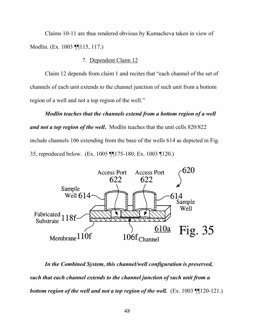
7. Dependent Claim 12
Claim 12 depends from claim 1 and recites that “each channel of the set of
channels of each unit extends to the channel junction of such unit from a bottom
region of a well and not a top region of the well.”
Modlin teaches that the channels extend from a bottom region of a well
and not a top region of the well. Modlin teaches that the unit cells 820/822
include channels 106 extending from the base of the wells 614 as depicted in Fig.
35, reproduced below. (Ex. 1005 ¶¶175-180; Ex. 1003 ¶120.)
In the Combined System, this channel/well configuration is preserved,
such that each channel extends to the channel junction of such unit from a
bottom region of the well and not a top region of the well. (Ex. 1003 ¶¶120-121.)

49
As explained above, in the Combined System the parallel emulsion generator units
of Kumacheva are modified according to the microplate well configuration of
Modlin. Id. In the non-limiting example depicted below, the Kumacheva droplet
generators 36 are positioned at the junctions of Modlin’s unit cell 822. (Ex. 1004
¶62; Ex. 1017 pp. 16-18; Ex. 1005 ¶¶208-214; Ex. 1003 ¶120.) The unit cells have
the structure shown in Fig. 35, reproduced above. (Ex. 1003 ¶120.)
Claim 12 is thus rendered obvious by Kumacheva taken in view of Modlin.
(Ex. 1003 ¶122.)
8. Dependent Claim 13
Claim 13 depends from claim 1 and recites that “wherein the plate includes
an upper member attached to a lower member, wherein the upper member forms
side walls of the wells of each unit and also forms top and side walls of each
channel of the set of channels of each unit, and wherein the lower member extends
under each well and channel of the unit to form a bottom wall of such well and
channel.”

50
Modlin teaches that the channels and wells are formed in a substrate and
that the bottom walls of those structures are provided by a lower member, as
recited in claim 13. Modlin teaches that the unit cells 820/822 include channels
106 formed in substrate 118 and a membrane 110 forming the bottom of the
channels 106, as depicted in Fig. 35, reproduced at right. (Ex. 1005 ¶¶175-180;
Ex. 1003 ¶124.) Accordingly, the plate includes an upper member (substrate 118
(including wells 614/622)) attached to a lower member (membrane 110), wherein
the upper member forms side
walls of the wells (614) of each
unit and also forms top and side
walls of each channel (106) of
the set of channels of each unit,
and wherein the lower member (110) extends under each well (614/622) and
channel of the unit to form a bottom wall of such well and channel as recited in
claim 13. (Ex. 1003 ¶125.)
In the combined system of Kumacheva and Modlin, this channel/well
configuration is preserved, thus meeting the recitations of claim 13. (Ex. 1003
¶125.) This aspect of the Combined System is discussed above in connection with
claim 1.

51
Claim 13 is thus rendered obvious by Kumacheva taken in view of Modlin.
(Ex. 1003 ¶126.)
9. Dependent Claim 14
Claims 14 depends from claims 1 and 13 and recites that “the upper member
is formed of an injection-molded polymer.”
The specification does not identify any unexpected result associated with
fabrication by injection molding. To the contrary, the specification merely states
that the upper member “may be manufactured by any suitable method, such as by
injection molding a thermoplastic material.” (Ex. 1001 at 60:28-29.)
As discussed above in connection with claim 13, Modlin teaches that the
plate includes an upper member (substrate 118 including wells 614). (Ex. 1003
¶127.)
Modlin teaches that injection molding may be advantageously used to
fabricate the upper members of the plates. (Id.) “Manufacturing of the
assemblies of the present teachings may be carried out by any number of
microfabrication techniques that are well known in the art.” (Ex. 1005 ¶160, see
also ¶¶131, 133.) “[F]or polymeric substrates, well known manufacturing
techniques may also be used. These techniques include injection molding
techniques or embossing or stamp molding methods . . ..” (Id.) “It is to be

52
understood that the present teachings are not limited to fabrication by one or the
other of these methods.” (Id.)
In the Combined System, a skilled artisan would have been strongly
motivated to make the upper member (substrate 118 and wells 614) via injection
molding as suggested by Modlin. (Ex. 1003 ¶128.) Injection molding was well-
known to be an economical process and that a variety of thermoplastics having
good optical and mechanical properties can be processed by injection molding to
form the desired structures. (See Ex. 1028 at 1:34-41; Ex. 1003 ¶128.) Indeed, as
early as the 1990s is was taught that “[m]icrochannel structures . . . are typically
produced by injection molding using various thermoplastic polymers.” (Ex. 1028
at 1:34-41.) In 1998 Dr. Gandhi filed a patent application teaching improved
methods for sealing injection molded microfluidic plates. (Ex. 1012 at 7:63-8:57;
Ex. 1003 ¶128.) By 2008, “[p]olymers [had] assumed the leading role as substrate
materials for microfluidic devices.” (Ex. 1041 p. 1; Ex. 1042.) “The big
advantages of injection molding are the ability to form three-dimensional objects,
which, in the case of microfluidic devices, means e.g. the integration of fluidic
interconnects . . . or through-holes. Furthermore, the ejected part does not
normally need additional mechanical process steps, thus reducing the production
time further. Owing to the highly industrialized development of the process, a large

53
variety of equipment suppliers are available as well as automation solutions for
large-volume manufacturing.” (Id. p. 12.)
Because injection molding was one of the leading techniques for forming
microfluidic plates at the time of filing, a skilled artisan would have had a strong
expectation that the Combined System could be successfully fabricated by
injection molding. (Ex. 1003 ¶128.) As of September 2008, skilled artisans
understood that microfluidic chips would be manufactured according to a variety
of well-known processes, including injection molding. (Ex. 1028 at 1:34-41,
10:33-39, 4:20-13:64; Ex. 1025 pp. 2-14; Ex. 1040; Ex. 1041 at 12; Ex. 1006 p. 2;
Ex. 1032; Ex. 1003 ¶128.) Further, the plate or chip may be of an arbitrarily large
size, which further simplifies the task of fabricating the upper members of the
plates by injection molding. (Ex. 1003 ¶128.) Such would require no more than
routine skill and would lead to predictable results. (Id.)
Claim 14 is thus rendered obvious by Kumacheva taken in view of Modlin.
(Ex. 1003 ¶129.)
10. Dependent Claims 15
Claims 15 depends from claim 14 and recites that “each of the upper and
lower members is formed by a respective, continuous piece of material.”

54
Modlin’s lower member (membrane 110) is formed of a continuous piece
of material. (Ex. 1003 ¶130.) The membrane 110 is continuous, as shown in Fig.
35, reproduced below, as well as Figs. 18-32, which illustrate the fabrication
process. (Ex. 1005 ¶¶155-174; Ex.
1003 ¶130.) The lower member of the
Combined System has this same
structure and thus meets claim 15. (Ex.
1003 ¶131.)
Especially when the upper member (substrate 118 and wells 614) is formed
by injection molding (as suggested by Modlin), it would have been obvious to
fabricate Modlin’s upper member from a single piece of material. (Ex. 1005
¶160; Ex. 1003 ¶130.) Doing so would substantially simplify the manufacturing
process and reduce cost. (Id.) Other advantages of injection molding are discussed
above in connection with claim 14.
A skilled artisan would have considered it routine to fabricate the
substrate 118 and wells 614 of the Combined System in a single piece by
injection molding at the time of filing. (Ex. 1003 ¶131.) Such structures were
commonly integrally formed by injection molding at the time of filing. (Ex. 1008
¶72; Ex. 1011 ¶69; Ex. 1041 p. 12, Ex. 1003 ¶131.) For instance, in 2008 BioScale
filed an application directed to a microfluidic plate with input wells 332 and output

55
wells 342, and explained that the entire body could be formed by injection
molding. (Ex. 1008 ¶72; see also Ex. 1011 ¶69.) In 2006 Mair explained that the
microfluidic chip shown below (including the upwardly extending inlets) was
integrally molded from a single piece of plastic (excluding, of course, the threaded
inserts). (Ex. 1047p. 6, Fig. 5; Ex. 1048; Ex. 1008 ¶72; Ex. 1011 ¶69.)
For these reasons, in the Combined System it would have been obvious to
fabricate each of the upper member and the lower member from a continuous piece
of material, thus meeting the recitations of claim 15. (Ex. 1003 ¶131.)
Claim 15 is thus rendered obvious by Kumacheva taken in view of Modlin.
(Ex. 1003 ¶132.)
11. Dependent Claim 16
Claim 16 depends from claim 1 and recites “wherein the plate includes an
upper member attached to a lower member, wherein the upper member includes
upper and lower surfaces, wherein the upper member defines through-holes
corresponding to the wells of each unit and extending from the upper surface to the

56
lower surface and also defines grooves corresponding to the set of channels of each
unit and formed in the lower surface, and wherein the lower member is attached to
the upper member at the lower surface to form a bottom wall below each through-
hole and groove.”
Modlin teaches an upper member (substrate 118 and wells 614) having
through holes 614/622 which extend therethrough and grooves that define
channels 106 formed in the underside of the substrate. (Ex. 1003 ¶134.) Modlin
teaches that the unit cells 820/822 include substrate 118 (upper member) including
channels 106 formed in the lower surface thereof and through holes 614/622
defining wells, as depicted in Fig. 35 reproduced below. (Ex. 1005 ¶¶175-180; Ex.
1003 ¶134.)
Modlin teaches a lower member (membrane 110) having a surface that
forms a bottom wall below each through-hole and groove. (Ex. 1003 ¶134.) As
illustrated in Fig. 35, above, membrane 110 (lower member) forms the bottom of

57
the channels 106 and extending below the through holes 622, as depicted in Fig. 35
reproduced below. (Ex. 1005 ¶¶175-180; Ex. 1003 ¶134.)
In the Combined System, the unit cells have this same structure, thus
meeting the recitations of claim 16. (Ex. 1003 ¶134.)
Claim 16 is thus rendered obvious by Kumacheva taken in view of Modlin.
(Ex. 1003 ¶135.)
12. Dependent Claim 17
Claim 17 recites that “the lower member is a sheet of material that is
substantially thinner than the upper member.” The ’392 does not define what
“substantially thinner” means; rather, the ‘392 specification merely teaches that
“[m]aintaining lower internal operating pressures rather than higher pressures also
means that the cartridge can have . . . (c) thinner plates bonded to the microchannel
side of the cartridge.” (Ex. 1001 at 88:57-63.)
Modlin’s membrane 110 is substantially thinner than the upper member
(substrate 118 and wells 614), thus meeting the recitations of claim 17. Modlin
teaches that the unit cells 820/822 include substrate 118 (upper member) and a
substantially thinner membrane
110 (lower member) forming the
bottom of the channels 106, as
depicted in Fig. 35 reproduced

58
below. (Ex. 1005 ¶¶175-180; Ex. 1003 ¶136.) Modlin teaches that the membrane
“may be fabricated with a thickness in the range of 10 to 100 microns or
alternatively in the range of 1-50 microns.” Ex. 1005 ¶¶129, 322.) The upper
member (substrate 118 and wells 614) must be at least several millimeters tall.
(Ex. 1003 ¶136.) Assuming an upper member just 5 mm (5,000 microns) tall and a
lower member (membrane) 50 microns thick, the lower member is 100X thinner
than the upper member, thus meeting the recitations of claim 17. (Id.)
In the Combined System, the unit cells have this same structure, thus
meeting the recitations of claim 17. (Ex. 1003 ¶138.)
Claim 17 is thus rendered obvious by Kumacheva taken in view of Modlin.
(Ex. 1003 ¶139.)
13. Dependent Claim 19
Claim 19 depends from claim 1 and recites that “the plate includes an upper
member attached to a lower member to form an array of emulsion production units
each configured to produce a separate emulsion, and wherein the lower member
has an upper surface that is flat and that abuts a lower surface of the upper member
to form a bottom wall of openings formed in the lower surface and corresponding
to the wells and the channels of each unit.”
This claim recites features duplicative to those recited in claims 13 and 16
except that 19 further recites that each emulsion production unit is “configured

59
to produce a separate emulsion.” The discussion of claims 13 and 16 is
incorporated by reference. In the Combined System described in connection with
Claim 1, each unit cell has its own output well 2 which receives an emulsion from
the droplet generator of that unit cell. (Ex. 1003 ¶¶140-141.) Each unit cells thus
includes an emulsion production unit that produces an emulsion separate from the
other unit cells, thus meeting the recitations of claim 19. (Id.)
Claim 19 is thus rendered obvious by Kumacheva taken in view of Modlin.
(Ex. 1003 ¶142.)
14. Dependent Claim 20
Claim 20 depends from claims 1 and 19 and recites that “each of the upper
and lower members is formed by a respective, continuous piece of material.”
The discussion of claim 15 is incorporated herein by reference. As
explained therein, it would have been obvious to fabricate the upper and lower
members of a respective, continuous piece of material.
Claim 20 is thus rendered obvious by Kumacheva taken in view of Modlin.
(Ex. 1003 ¶¶143-146.)
15. Dependent Claim 21
Claim 21 depends from claim 1 and recites that “at least one first input well
of each emulsion production unit is not shared with other emulsion production
units of the plate.”

60
In the Combined System described in connection with claim 1, each unit cell
includes an emulsion generator and each has an input well that is not shared with
other emulsion generators in other unit cells. (Ex. 1003 ¶147.) The Combined
System thus meets claim 21. (Id.)
Claim 21 is thus rendered obvious by Kumacheva taken in view of Modlin.
(Ex. 1003 ¶148.)
B. Ground 2: Claims 2 and 5 Are Rendered Obvious by Kumacheva in View of Modlin and Further in View of Chien
1. Dependent Claim 2
Claim 2 depends from claim 1 and recites that “the vacuum or pressure
source controls air pressure in wells to which the source is configured to be
connected operatively.”
In the Combined System discussed above in connection with claim 1, the
microfluidic well plate assembly 610 has an array FFD-containing unit cells and is
placed in contact with Modlin’s pressure
manifold 754. The manifold 754 provides
pneumatic (air) pressure to drive the fluids
among the microwells 1-4 in each unit cell
822. (Ex. 1005 ¶¶187-88, 202; Ex. 1003
¶149.) However, because Modlin’s

61
discussion of the pneumatic control is abbreviated, Petitioner relies upon Chien for
its teaching of using air pressure in the wells to drive the fluids. (Ex. 1003 ¶150.)
Chien teaches that it is preferable to drive fluids through microfluidic
chips with a manifold that delivers air pressure to the headspace above the
reservoirs of fluid stored in on-chip wells. (Ex. 1007 pp. 1-3.) Chien explained
that this method substantially improves the accuracy of the fluid flow control
relative to the previously reported approaches of pumping fluids directly into the
microchannels from a source outside the chip or using on-chip micropumps. (Id.)
The latter approaches were found to produce, relatively speaking, inconsistent or
“erratic” results. (Id.)
A skilled artisan would have been strongly motivated to use Chien’s
technique to improve upon the combined Kumacheva/Modlin device. (Id.; Ex.
1003 ¶151.) Modlin expressly suggests use of air pressure to drive the fluids in the
wells, stating that “[a] plurality of connectors 712 are disposed within well frame
body 710 to direct sources of externally generated and controlled pneumatic or
hydraulic pressure to the plurality of wells 728.” (Ex. 1005 ¶187.) “Tapered plugs
714 or equivalent alternative means is provided to seal the well entrances allowing
the externally controlled pressure directed through connectors 712 to wells 728
to build up within the wells and provide a driving force for flow within the
channels of assembled chip 542.” (Id.). The build-up of pneumatic (as opposed to

62
hydraulic) pressure in the wells corresponds to the technique taught in more detail
in Chien. (Ex. 1003 ¶151.) As noted by Chien, using this technique enables more
precise and reproducible control of the fluid flows. (Ex. 1007 pp. 1-3; Ex. 1003
¶151.)
Because each of the components of the Combined System were well known
at the time of filing, a skilled artisan would have had a strong expectation that the
Combined System could be modified as taught by Chien and would work as
intended. (Ex. 1003 ¶152.)
Claim 2 is thus rendered obvious when Kumacheva and Modlin are taken
further in view of Chien. (Ex. 1003 ¶153.)
2. Dependent Claim 5
Claim 5 depends from claim 1 and recites that “the vacuum or pressure
source is a vacuum source configured to form a pressure sink at the output wells of
the plate when the vacuum source is connected operatively to the output wells.”
Chien teaches creating a vacuum in the headspace above the reservoir of
fluid stored in on-chip wells. (Ex. 1003 ¶154.) Chien teaches that an “eight-
syringe pump system is used as [the] pressure or vacuum source. . . The incubation
time is controlled by the vacuum applied to the waste well.”. (Ex. 1007 pp. 2, 3,
5.) The “waste well” is an output well. The ‘392 patent does not define “output.”
However, dependent claim 18 recites the performance of a PCR reaction on the

63
device, after which the droplets would typically be optically analyzed (also on the
device) and then discarded. Indeed, if the analytical test of interest has already
been performed on the droplets before they arrive at the output well, as in Chien,
then the droplets may be discarded. (Ex. 1039 at 21:13-38, 23:30-35; Ex. 1007 p.
5; Ex. 1003 ¶154.) The claim is open ended with respect to the output – the output
well can collect either waste or droplets to be further analyzed. (Ex. 1003 ¶154.)
Both are “output” in the context of the recited device. (Id.) Accordingly, Chien
teaches application of a vacuum to create a pressure sink at an “output well” as
recited in claim 5. (Id.)
As explained above in connection with claim 2, one skilled in the art would
have considered it obvious to use Chien’s technique to drive fluids from the wells
and through the microchannels of plate in the Kumacheva/Modlin system. (Id.)
Claim 5 is thus rendered obvious when Kumacheva and Modlin are taken
further in view of Chien. (Ex. 1003 ¶155.)
C. Ground 3: Claim 7 Is Rendered Obvious by Kumacheva in View of Modlin and Further in View of Hsieh
Claim 7 depends from claim 1 and recites that the “wells of each unit
include only one first input well configured to hold the continuous phase, and
wherein a pair of channels of the set of channels of each unit extend separately
from one another to the channel junction of such unit from the only one first input
well.”

64
Hsieh’s channels extend separately to a droplet generation junction from
one continuous phase inlet. Hsieh uses a “flow focusing” droplet generation
approach (see Technical Background) in which opposing flows of oil pinch off
droplets at a channel junction. Hsieh
teaches that “substrate 14 includes a
first inlet 16 that is configured to
contain a carrier material 18 for the
droplets 60. Generally, the carrier material 18 may include an immiscible
continuous phase material such as, for instance, oil.” (Ex. 1019 ¶22.) “The first
inlet 16 is fluidically coupled to two separate channels 20, 22 that terminate in
a junction or droplet generation region 24.” (Id.) “[T]he droplet generation
region 24 includes a pinch-off area or region that ‘pinches-off’ droplets generated
from the streams flowing from the second inlet 30 and third inlet 40.” (Id.)
Accordingly, Hsieh teaches (a) an emulsion production unit having only one first
inlet 16 to hold the continuous phase (oil) and (b) a pair of separate channels 20, 22
that extend separately to the junction 24 from the inlet 16.
A skilled artisan would have been strongly motivated to modify the
Combined System (Kumacheva/Modlin) to use a single inlet (as taught by Hsieh)
to feed the continuous phase channels leading to the emulsion generator
junction. (Ex. 1003 ¶160.) This modification of the Combined System is

65
illustrated below. (Id.) The 4-well unit cell 822 in the Combined System is
replaced with a 3-well unit cell. (Id.)
A skilled artisan would have seen at least two reasons to make this
modification. (Id.) First, as discussed above for claims 10-11, using a single input
well for the continuous phase in each unit cell reduces the number of manifold-to-
well seals and thus not only simplifies the instrument but also reduces the risk of
leaks. Id.) Second, doing so would save space and permit more droplet generators
to be provided on a single chip. (Id.) Given that the input and output wells are
substantially larger than the microchannels, the number and positioning of the
input and output wells or ports is the primary factor controlling how closely the
microfluidic circuits may be spaced. (Id.) For the most compact arrangement, a
skilled in the art would use a single continuous phase well (first input well) as
recited in claim 7. (Id.)
A skilled artisan would thus have considered it obvious to use a single input
well to improve a similar system (the Combined System of Kumacheva and

66
Modlin) in the same way (to simplify the instrument and save space on the chip).
KSR, 550 U.S. at 415-421 (2007) (Ex. 1003 ¶¶160-161.)
In light of the level of skill of art, a skilled artisan would have found it
routine to make the foregoing combination (yielding the claimed limitation). (Ex.
1003 ¶161.)
D. Ground 4: Claim 18 Is Rendered Obvious by Kumacheva in View of Modlin and Further in View of Beer
Claim 18 depends from claim 1 and recites that “the first input well of a unit
contains a nonaqueous continuous phase, wherein the second input well of such
unit contains an aqueous phase configured for PCR amplification, and wherein the
output well of such unit contains an emulsion including droplets of the aqueous
phase disposed in the nonaqueous continuous phase.” Claim 18 is rendered
obvious by Kumacheva and Modlin taken further in view of Beer. (Ex. 1003
¶¶162-166.)
Beer teaches performing PCR in droplets formed with microfluidic
emulstion generators. “To generate water-in-oil (w/o) microdroplets, we
utilized a chip (Figure 1a) with hydrophobic channel surfaces and a shearing cross-
flow Tjunction.” (Ex. 1034 p. 2.) “Two infusion syringe pumps (KD Scientific)
independently drove the aqueous and oil (M8662, Sigma-Aldrich) streams at
predetermined flow rates of 2.3 and 0.3 mL/h, respectively.” (Id.) “A mixture of

67
nucleic acid sample and PCR reagents was injected into the aqueous stream
and delivered to the chip.” (Id.)
As discussed above in connection with claim 2, a “waste” well is an output
well. That discussion is incorporated herein by reference.
When the Combined System of claim 1 is used to perform PCR as taught
by Beer the Combined System meets claim 18. (Ex. 1003 ¶163.) In the
illustrative combined system depicted below, oil is added to the first input well (1,
4), aqueous PCR reagents are added to the second input well (3), and the resulting
emulsion is collected in the output well (2) of the combined system, thus meeting
the recitations of claim 18. (Id.)

68
One skilled in the art would have been motivated to use the Combined
System to perform PCR as taught by Beer and in accordance with claim 18. (Ex.
1003 ¶¶164-165.) Kumacheva expressly suggests using the device to perform PCR
by noting that “[m]ultichannel microfluidic devices have been used for DNA
separation, parallel PCR assays, detection of enzymatically-generated
fluorescence and linear temperature gradients, capillary electrophoresis for
immunoassays, and chiral separation.” (Ex. 1004 ¶14; Ex. 1017 pp. 9-10.)
Combining the Kumacheva/Modlin system with Beer would provide a PCR
instrument that provides “a level of control over microdroplet
compartmentalization not achievable by ‘shake-and-bake’ methods.” (Ex. 1034 p.
2.) Beer also teaches that his method his method allows “detection of a single
copy of nucleic acid at significantly reduced cycle thresholds and will benefit from
the high-throughput and low reagent usage architecture that on-chip processes
provide.” Accordingly, a skilled artisan would have been motivated to use the
technique taught in Beer (PCR in picoliter sized droplets) to improve a similar
device (the Kumacheva/Modlin system) in the same way (providing improved
control and detection). KSR, 550 U.S. at 415-421 (2007).
In light of the level of skill of art, a skilled artisan would have found it
routine to make the foregoing combination (yielding the claimed limitation). (Ex.
1003 ¶166.)

69
E. Ground 5: Claims 12-17 and 19-20 Are Rendered Obvious by Kumacheva in view of Modlin and Further in view of Soane
Claims 12-17 and 19-20, which depend directly or indirectly from claim 1,
are rendered obvious by Kumacheva in view of Modlin and further in view of
Soane.
Soane teaches “[m]ethods for fabricating enclosed microchannel
structures.” (Ex. 1028, Title.) “The microchannel structures are constructed of a
base plate and a cover . . . [these microchannels] are enclosed by bonding the
planar surfaces of the cover
and the base plate together.”
(Id. Abstract.) Shown in Fig.
6 (right) is “an assembled
microchannel device 10 made
by bonding a base plate 12 . . . to a cover 14.” (Id. at 5:35-38.) “Base 12 has a
planar surface 13 in which a microchannel structure is formed, including
intersecting linear microchannels 21, 23. At the ends of the channels holes 22, 24,
26, 28 are bored through, to provide reservoirs for fluids to be moved within the
channels.” (Id. at 5:45-49.) “Cover 11 has a generally planar surface 15, apposable
onto the channel-bearing surface 13 of base plate 12, onto which a thin film 16 of a
bonding material is applied. Microchannel device 10 is formed by opposing the
surfaces 13, 15 with the bonding material between them. As a result, the

70
microchannels 21, 23 are closed, having three walls formed in the base plate
surface 13, and a fourth wall formed by the cover 11, with the bonding material
film 16 constituting the surface of the fourth microchannel wall.” (Id. at 5:55-64.)
“Reservoirs formed as described above are open on a surface of the base plate
opposite the surface apposed to the cover.” (Id. at 5:65-67.)
A skilled artisan would have been motivated to fabricate the Combined
System of Kumacheva/Modlin using Soane’s methods. First, Soane teaches that
his injection-molding based methods “would be much more economical, and
therefore desirable” than other methods such as photolithography. (Ex. 1028 at
2:7-10.) Soane explains that “microchannel structures . . . are typically produced
by injection molding using various thermoplastic polymers. Injection molding is an
economical process, and a variety of thermoplastics having good optical and
mechanical properties can be processed by injection molding to form the desired
structures.” (Id. at 1:27-38.) Second, Soane demonstrated his methods created
“polymeric microchannel structures . . . [w]ithout deformation, partial or complete
clogging of the enclosed microchannels.” (Id. 13:42-49.) Accordingly, Soane
permits the realization of the benefits of injection molding without any potential
disadvantages which would prevent its use in the context of the Combined System.
(Ex. 1003 ¶169.)

71
One skilled in the art would have had a reasonable expectation of success
using the Soane method to fabricate the Combined System. (Ex. 1003 ¶170.)
Soane provides various working examples which could be directly applied to
fabricate the Combined System. (Id.) In light of the level of skill of art, a skilled
artisan would have found it routine to make the foregoing combination and would
fully expect that the combination (yielding the claimed limitation) would work as
expected (Id.)
1. Dependent Claim 12
The text of claim 13 is reproduced in Section VIII.A.7.
Soane teaches channels that extend to a channel junction from a bottom
region of a well. As shown in Fig. 6 (right), “[b]ase 12 has a planar surface 13 in
which a microchannel structure is formed, including intersecting linear
microchannels 21, 23. At the ends of the channels holes 22, 24, 26, 28 are bored
through, to provide reservoirs
for fluids to be moved within
the channels.” (Ex. 1028 at
5:45-49, see also 5:50-67.) As
depicted in Fig. 6, these microchannels 21, 23 extend from the bottom (not top)
regions of these reservoirs 22, 24, 26, thus meeting the recitations of claim 12.
(Ex. 1003 ¶¶172, 174.)

72
2. Dependent Claim 13
The text of claim 13 is reproduced in Section VIII.A.8.
Soane teaches an upper member (base plate 12) forms side walls of the
wells (holes 24, 26) of each unit and also forms top and side walls of each
channel (channels 21/23) and the lower member (film 16 or, alternatively, film
16 and cover 14) extending under each well and channel of the unit to form a
bottom wall of such well and channel. (Ex. 1003 ¶175.) “Cover 11 has a
generally planar surface 15, apposable onto the channel-bearing surface 13 of base
plate 12, onto which a thin film 16 of a bonding material is applied. Microchannel
device 10 is formed by apposing the surfaces 13, 15 with the bonding material
between them.” (Ex. 1028 at
5:55-60.) “As a result, the
microchannels 21, 23 are closed,
having three walls formed in
the base plate surface 13, and
a fourth wall formed by the cover 11, with the bonding material film
constituting the surface of the fourth microchannel wall.” (Ex. 1028 5:55-64,
see also Examples 1-8 at 9:65-13:7.) The Soane structure thus meets claim 13. (Ex.
1003 ¶175.)

73
3. Dependent Claim 14
The text of claim 14 is reproduced in Section VIII.A.9.
Soane teaches an upper member (base plate 12) formed of an injection
molded polymer. “Microchannel structures . . . are typically produced by injection
molding using various thermoplastic polymers.” (Ex. 1028 at 1:27-35.)
“[I]njection molding techniques were used to prepare a microchannel base plate of
an acrylic polymer (AtoHaas, PlexiglasTMV825NA-100).” (Ex. 1028 at 10:36-40,
see also 11:27-31, 12:7-13:7.) The Soane base plate 12 thus meets claim 14. (Ex.
1003 ¶¶176-177.)
4. Dependent Claim 15
The text of claim 15 is reproduced in Section VIII.A.10.
Soane discloses that each of the base plate 12 (the upper member) and the
bonding material film 16 (the lower member) is formed by a continuous piece of
material. “In general, the microchannel structures according to the invention are
constructed of two parts, each having at least one generally planar surface, sealed
together so that the generally
planar surfaces are apposed.
One part is referred to as a
base plate, and the other is
referred to as a cover.” (Ex.

74
1028 at 4:59-66.) The base plate 12 is formed by injection molding, which results
in a plate made from a single, continuous piece of material. (Ex. 1028 at 10:36-40,
see also 11:27-31, 12:7-13:7; Ex. 1003 ¶178.) “The cover [11] may be a more or
less rigid plate, or it may be a film . . . . [and] may be fabricated from a single
material or be fabricated as a composite material.” (Ex. 1028 at 4:66-5:7.) In
Example 2, for instance, the cover 11 is a continuous Mylar film coated with an
adhesive such that the adhesive layer may be considered the lower member. (Id. at
10:29-57; see also 5:55-64.) In Fig. 6, the lower member is depicted as “bonding
material film 16.” (Id.) The base plate 12 and bonding material film 16 of Soane
are each made of a continuous piece of material and thus meet claim 15. (Ex. 1003
¶179.)
5. Dependent Claim 16
The text of claim 16 is reproduced in Section VIII.A.11.
Soane includes an upper member (base plate 12) having an upper surface
defining through-holes (22, 24, 26) corresponding to the wells extending to its
lower surface which has grooves (21,23) corresponding to the set of channels,
and a lower member (film 16
or, alternatively, film 16 and
cover 14) that forms a bottom
wall below each through-hole

75
and groove. (Ex. 1028 at 5:45-64, see also Examples 1-8 at 9:65-13:7. Ex. 1003
¶181.) The base plate 12 and bonding material film 16 of Soane thus meet claim
16. (Ex. 1003 ¶¶181-182.)
6. Dependent Claim 17
The text of claim 13 is reproduced in Section VIII.A.12.
Soane teaches that the lower member (film 16 or, alternatively, film 16 and
cover 14) can be a sheet of material that is substantially thinner than the upper
member (base 12). In Fig. 5-6 of Soane, the bonding material film (lower
member) is depicted as being substantially thinner than the base plate 12. (Ex.
1028 at 4:47- 6:30; Ex. 1003 ¶183.)
As to the lower member (bonding material 16) Soane teaches that “[i]n practice,
generally, the bonding material usually is applied to a thickness at least about 0.5
µm, in some embodiments at least about 1 µm, and in still other embodiments at
least about 2 µm.” (Ex. 1028 at 6:26-30.) As to the base plate 12 into which the

76
channels are formed, Soane teaches that “the thickness of the polymeric material
[in which the channels are formed] will be at least about 1 µm, usually at least
about 5 µm, and more usually at least about 50 µm, where the thickness may be as
great as 5 mm or greater.” (Ex. 1028 at 4:47-51.) Soane thus teaches that the
bonding material 16 is usually on the order of 1µm whereas the base plate 12 is
usually on the order of at least 50 µm.
In the alternative, if bonding material 16 and cover 14 are together
considered the lower member, Example 2 teaches that the cover 14 may be a 2 mil
(50.8 micron) sheet of Mylar. (Ex. 1028 at 10:45-50.) The lower member would
thus be 51 µm and Soane teaches that the base plate 12 (upper member) would be 5
mm (5,000 um) or greater.
Under either approach, Soane thus meets the recitations of claim 17.
7. Dependent Claim 19
The text of claim 19 is reproduced in Section VIII.A.13.
This claim recites features duplicative to those recited in claims 13 and 16
except that 19 further recites that each emulsion production unit is “configured
to produce a separate emulsion.” The discussion of claims 13 and 16 is
incorporated by reference. In the Combined System described in connection with
Claim 1, each unit cell has its own output well 2 which receives an emulsion from
the droplet generator of that unit cell. (Ex. 1003 ¶185.) Each unit cells thus

77
includes an emulsion production unit that produces an emulsion separate from the
other unit cells, thus meeting the recitations of claim 19.
8. Dependent Claim 20
The text of claim 13 is reproduced in Section VIII.A.15.
The discussion of claim 15 is incorporated herein by reference. As
explained therein, it would have been obvious to fabricate the upper and lower
members of a respective, continuous piece of material.
For the foregoing reasons claims 12-17 and 19-20 are rendered obvious by
Kumacheva and Modlin taken further in view of Soane. (Ex. 1003 ¶167-188.)
IX. SECONDARY CONSIDERATIONS OF NONOBVIOUSNESS CANNOT OVERCOME THE OBVIOUSNESS GROUNDS Petitioner is unaware of any objective indicia of nonobviousness that would
overcome the obviousness grounds set forth above. Petitioner is not aware of any
industry praise of the subject matter recited in the challenged claims. Neither
Patent Owner’s website nor its complaint in Bio-Rad Laboratories, Inc., et al. v.
10X Genomics, Inc., Case No. 3:17-cv-4339 (N.D. Cal.) assert that the ‘392 patent
was praised in the industry. Nor does Patent Owner therein allege commercial
success, copying, failure of others, unexpected results, long-felt need or industry
acquiescence, much less attempt to establish any nexus between such objective

78
indicia and any novel aspect of the claimed subject matter. Novartis AG v. Torrent
Pharmaceuticals Ltd., 853 F. 3d 1316, 1331 (Fed.Cir. 2017).
X. CONCLUSION
For the foregoing reasons, claims 1-21 of the ‘392 patent recite subject
matter that would have been considered obvious by a skilled artisan at the time of
filing. Petitioner requests institution of an inter partes review to cancel those
claims.
Respectfully submitted,
Date: December 14, 2017 /Greg H. Gardella/ Greg H. Gardella, Reg. No. 46,045
Gardella Grace P.A. 455 Massachusetts Ave. NW, Suite 507 Washington, DC 20001 Tel: (703) 740-4540

WORD COUNT CERTIFICATE OF COMPLIANCE
I hereby certify that the foregoing petition for inter partes review complies
with 37 C.F.R. § 42.24 because it contains 13,474 words as measured by the word
processing software used to prepare the document, including footnotes and the
reproduction of the claim language but excluding the table of contents, mandatory
notices under §42.8, certificate of service or word count, and appendix of exhibits.
Date: December 14, 2017 /Greg H. Gardella/ Greg H. Gardella, Reg. No. 46,045
Gardella Grace P.A. 455 Massachusetts Ave. NW, Suite 507 Washington, DC 20001 Tel: (703) 740-4540

CERTIFICATE OF SERVICE
The undersigned certifies service pursuant to 37 C.F.R. §§42.6(e) and
42.105(b) on the Patent Owner by USPS Priority Mail Express of a copy of this
Petition for Inter Partes Review and supporting materials at the correspondence
address of record for the ‘392 patent to:
Kolisch Hartwell, P.C. 200 Pacific Building
520 SW Yamhill Street Portland OR 97204
Dated: December 14, 2017 /Greg H. Gardella/
Greg H. Gardella Reg. No. 46,045


![17 -FYC- SI V1 · î ì í ó & v z z z z o o v p ^ ] o ] v p / v µ ] } v ð ñ x í x 7r dohuw erdwv wkdw d udfh ru vhtxhqfh ri udfhv zloo ehjlq vrrq wkh rudqjh vwduwlqj olqh iodj](https://static.fdocuments.in/doc/165x107/601463a2fb75de26ce37c511/17-fyc-si-v1-v-z-z-z-z-o-o-v-p-o-v-p-v-v-.jpg)
![PERMIT APPLICATION [REPORT] · 7h[dv &rpplvvlrq rq (qylurqphqwdo 4xdolw\)rup 3, 6 &%3 3, 6 &%3 'dwh 5hjlvwudwlrq bbbbbbbbbbbb &rpsdq\ -&. %dwfk 3odqw //& $$5& (qylurqphqwdo ,qf](https://static.fdocuments.in/doc/165x107/610122ccb660326a0a0ed766/permit-application-report-7hdv-rpplvvlrq-rq-qylurqphqwdo-4xdolwrup-3.jpg)