2.5/3.3V Ultra-Precision 4:1 CML/LVPECL MUX with 1:2 ...
8
2.5/3.3V Ultra-Precision 4:1 CML/LVPECL MUX with 1:2 Fanout and Internal Termination SY58028/29/30U Evaluation Board March 2005 M9999-033105 [email protected] or (408) 955-1690 General Description The SY58028/29/30U evaluation boards are designed for convenient setup and quick evaluation of the respective devices. The boards are optimized to interface directly to 50 systems. The evaluation boards are configured for AC-coupled inputs and DC-coupled outputs. For applications that require AC-coupled outputs, step-by-step instructions for modifying the board are included. Data sheets and support documentations can be found on Micrel’s web site at www.micrel.com. Features • SY58028U, SY58029U, SY58030U • +2.5V or +3.3V power supply • AC-coupled inputs and DC-coupled outputs • Can be reconfigured for AC-coupled output operation Related Documentation • SY58028U, 2.5/3.3V Ultra-Precision 4:1 CML MUX w/ 1:2 Fanout and Internal Termination Data Sheet • SY58029U, 2.5/3.3V Ultra-Precision 4:1 LVPECL MUX w/ 1:2 Fanout and Internal Termination Data Sheet • SY58030U, 2.5/3.3V Ultra-Precision 4:1 400mV LVPECL MUX w/ 1:2 Fanout and Internal Termination Data Sheet ____________________________________________________________________________________ Evaluation Board SY58028U SY58029/30U
Transcript of 2.5/3.3V Ultra-Precision 4:1 CML/LVPECL MUX with 1:2 ...

2.5/3.3V Ultra-Precision 4:1CML/LVPECL MUX with 1:2 Fanout
and Internal Termination
SY58028/29/30U Evaluation Board
March 2005 [email protected] or (408) 955-1690
General DescriptionThe SY58028/29/30U evaluation boards are designedfor convenient setup and quick evaluation of therespective devices. The boards are optimized tointerface directly to 50 systems.
The evaluation boards are configured for AC-coupledinputs and DC-coupled outputs. For applications thatrequire AC-coupled outputs, step-by-step instructionsfor modifying the board are included.
Data sheets and support documentations can befound on Micrel’s web site at www.micrel.com.
Features• SY58028U, SY58029U, SY58030U
• +2.5V or +3.3V power supply
• AC-coupled inputs and DC-coupled outputs
• Can be reconfigured for AC-coupled outputoperation
Related Documentation• SY58028U, 2.5/3.3V Ultra-Precision 4:1 CML
MUX w/ 1:2 Fanout and Internal Termination DataSheet
• SY58029U, 2.5/3.3V Ultra-Precision 4:1 LVPECLMUX w/ 1:2 Fanout and Internal Termination DataSheet
• SY58030U, 2.5/3.3V Ultra-Precision 4:1 400mVLVPECL MUX w/ 1:2 Fanout and InternalTermination Data Sheet
____________________________________________________________________________________
Evaluation Board
SY58028U SY58029/30U

Micrel, Inc. SY58028/29/30U Evaluation Board
March 2005 [email protected] or (408) 955-1690
2
Evaluation Board DescriptionThe SY58028U is a CML evaluation board and theSY58029U and SY58030U are LVPECL and 400mVLVPECL evaluation board sharing the same design.
The default configuration for these boards is AC-coupled inputs and DC-coupled outputs. Theevaluation boards can be reconfigured in AC-coupledoutput configuration.
Input Interface
The evaluation board is shipped with input terminationand the input common mode voltage is set at VCC-1.3V, which can easily interface to any differentialsignal over the supply voltage without modifying theevaluation board.
SY58028U AC-Coupled Outputs
The SY58028U outputs can be reconfigured for AC-coupled outputs by replacing C7–C10 with 0.1 F,0402, capacitors. See the SY58028U evaluationboard schematic for more details.
SY58029/30U AC-Coupled Outputs
The SY58029/30U outputs can be reconfigured forAC-coupled outputs by replacing C7–C10 with 0.1 F,0402, capacitors and by adding 82 pull-downs toR3–R6. See the SY58029/30U evaluation boardschematic for more details.

Micrel, Inc. SY58028/29/30U Evaluation Board
March 2005 [email protected] or (408) 955-1690
3
Evaluation Board
SY58028U CML Evaluation Board
I/O C7-C10
AC-Coupled Input/DC-Coupled Output 0
AC-Coupled Input/AC-Coupled Output 0.1uF
Table 1. SY58028U Configuration
Note: The default configuration is AC-Coupled In/DC-Coupled Out.

Micrel, Inc. SY58028/29/30U Evaluation Board
March 2005 [email protected] or (408) 955-1690
4
Evaluation Board
SY58029/30U LVPECL Evaluation Board
I/O Power Supply VCC GND VEE R3-R6 C7-C10
AC-coupled Input/DC-coupled Output 2.5V +2V 0 -0.5V None 0
AC-coupled Input/DC-coupled Output 3.3V +2V 0 -1.3V None 0
AC-Coupled Input/AC-Coupled Output 2.5V 2.5V 0 0 50 0.1uF
AC-Coupled Input/AC-Coupled Output 3.3V 3.3V 0 0 100 0.1uF
Table 2. SY58029/30U Configuration
Note: The default configuration is AC-Coupled In/DC-Coupled Out.

Micrel, Inc. SY58028/29/30U Evaluation Board
March 2005 [email protected] or (408) 955-1690
5
DC-Coupled Evaluation Board SetupThe following steps describe the procedure for settingup the evaluation board:
SY58028U
For 2.5V operation
• VCC = +2.5V
• VEE = 0V
• GND = 0V
For 3.3V operation
• VCC = +3.3V
• VEE = 0V
• GND = 0V
SY58029/30U
For 2.5V operation
• VCC = 2.0V
• VEE = -0.5V
• GND = 0V
For 3.3V operation
• VCC = 2.0V
• VEE = -1.3V
• GND = 0V
1. Signal Generator: Using a differential signalsource, set the amplitude of each side of thedifferential pair to 400mV (800mV measureddifferentially). Set the offset to a positivevalue, the value of the offset is not critical,since the AC-coupled inputs will beautomatically biased. Turn off or disable theoutputs of the signal source.
2. I/O Cable Interface: Using equal length 50impedance coaxial cables connect the signalsource to the inputs on the evaluation board.Using equal length 50 impedance coaxialcables connect the outputs of the evaluationboard to the oscilloscope or othermeasurement device that has an internal50 termination. Unequal length cables arenot recommended since they introduce dutycycle distortion and unwanted signal delays.
3. Connect the trigger input of the scope to thetrigger output of the signal generator.
4. Program the channel selection using theevaluation boards dipswitch.
SEL1 SEL0 Channel
0 0 IN0
0 1 IN1
1 0 IN2
1 1 IN3
5. Enable the signal source and monitor theoutputs.
Evaluation Board LayoutLayer SY58028U SY58039/30U
L1 VCC and Signal GND and Signal
L2 VCC GND
L3 GND VCC and VEE
L4 VCC GND
Table 3. Layer Stack
Micrel, Inc. SY58028/29/30U Evaluation Board
March 2005 [email protected] or (408) 955-1690
6
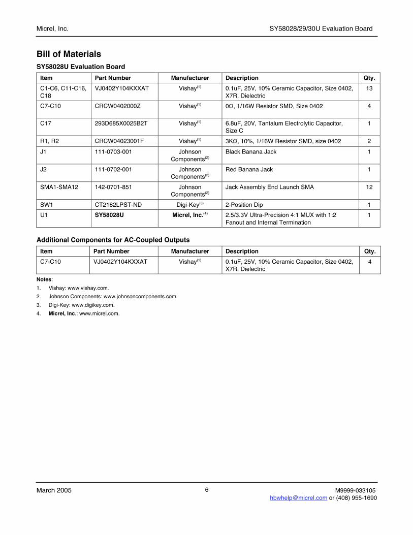
Bill of MaterialsSY58028U Evaluation Board
Item Part Number Manufacturer Description Qty.
C1-C6, C11-C16,C18
VJ0402Y104KXXAT Vishay(1) 0.1uF, 25V, 10% Ceramic Capacitor, Size 0402,X7R, Dielectric
13
C7-C10 CRCW0402000Z Vishay(1) 0 , 1/16W Resistor SMD, Size 0402 4
C17 293D685X0025B2T Vishay(1) 6.8uF, 20V, Tantalum Electrolytic Capacitor,Size C
1
R1, R2 CRCW04023001F Vishay(1) 3K , 10%, 1/16W Resistor SMD, size 0402 2
J1 111-0703-001 JohnsonComponents(2)
Black Banana Jack 1
J2 111-0702-001 JohnsonComponents(2)
Red Banana Jack 1
SMA1-SMA12 142-0701-851 JohnsonComponents(2)
Jack Assembly End Launch SMA 12
SW1 CT2182LPST-ND Digi-Key(3) 2-Position Dip 1
U1 SY58028U Micrel, Inc.(4) 2.5/3.3V Ultra-Precision 4:1 MUX with 1:2Fanout and Internal Termination
1
Additional Components for AC-Coupled Outputs
Item Part Number Manufacturer Description Qty.
C7-C10 VJ0402Y104KXXAT Vishay(1) 0.1uF, 25V, 10% Ceramic Capacitor, Size 0402,X7R, Dielectric
4
Notes:
1. Vishay: www.vishay.com.
2. Johnson Components: www.johnsoncomponents.com.
3. Digi-Key: www.digikey.com.
4. Micrel, Inc.: www.micrel.com.

Micrel, Inc. SY58028/29/30U Evaluation Board
March 2005 [email protected] or (408) 955-1690
7
SY58029/30U Evaluation BoardItem Part Number Manufacturer Description Qty.
C17-C19 293D685X0025B2T Vishay(1) 6.8uF, 20V, Tantalum Electrolytic Capacitor,Size C
2
C2-C6, C11-C16C18, C20
VJ0402Y104KXXAT Vishay(1) 0.1uF, 25V, 10% Ceramic Capacitor, Size0402, X7R, Dielectric
13
C7-C10 CRCW0402000Z Vishay(1) 0 , 1/16W Resistor SMD, Size 0402 4
R1, R2 CRCW04023001F Vishay(1) 3K , 10%, 1/16W Resistor SMD, size 0402 2
J1 111-0703-001 JohnsonComponents(2)
Black Banana Jack 1
J2, J3 111-0702-001 JohnsonComponents(2)
Red Banana Jack 2
SMA1-SMA12 142-0701-851 JohnsonComponents(2)
Jack Assembly End Launch SMA 12
SW1 CT2182LPST-ND Digi-Key(3) 2-Position Dip 1
U1 SY58029/30U Micrel, Inc.(4) 2.5/3.3V Ultra-Precision 4:1 MUX with 1:2Fanout and Internal Termination
1
Additional Components for AC-Coupled Outputs
Item Part Number Manufacturer Description Qty.
C7-C10 VJ0402Y104KXXAT Vishay(1) 0.1_F, 25V, 10% Ceramic Capacitor, Size0402, X7R, Dielectric
4
R3-R6 CRCW040249R9F
CRCW04021000F
Vishay(1) 10% 1/16W Resistor SMD, size 0402, Note 5 4
Notes:
1. Vishay: www.vishay.com.
2. Johnson Components: www.johnsoncomponents.com.
3. Digi-Key: www.digikey.com.
4. Micrel, Inc.: www.micrel.com.
5. For 2.5V operation: R1-R6 are 50 resistors: For 3.3V operation: R1-R6 are 100 resistors.

Micrel, Inc. SY58028/29/30U Evaluation Board
March 2005 [email protected] or (408) 955-1690
8
Micrel Cross ReferenceTo find an equivalent Micrel part, go to Micrel’swebsite at: http://www.micrel.com and follow thesteps below:
1. Click on Dynamic Cross Reference.
2. Enter competitor’s part number in theDynamic Cross Reference field.
3. To download a PDF version of thisinformation, click on the Cross ReferencePDF tab.
HBW SupportHotline: 408-955-1690
Email Support: [email protected]
Application Hints and NotesFor application notes on high speed termination onPECL and LVPECL products, clock synthesizerproducts, SONET jitter measurement, and other HighBandwidth products go to Micrel’s website athttp://www.micrel.com/. Once in Micrel’s website,follow the steps below:
1. Click on “Product Info.”2. In the Applications Information Box, choose
“Application Hints and Application Notes.”
MICREL, INC. 1849 FORTUNE DRIVE SAN JOSE, CA 95131 USATEL +1 (408) 944-0800 FAX +1 (408) 474-1000 WEB http:/www.micrel.com
The information furnished by Micrel in this data sheet is believed to be accurate and reliable. However, no responsibility is assumed by Micrel forits use. Micrel reserves the right to change circuitry and specifications at any time without notification to the customer.
Micrel Products are not designed or authorized for use as components in life support appliances, devices or systems where malfunction of aproduct can reasonably be expected to result in personal injury. Life support devices or systems are devices or systems that (a) are intended forsurgical implant into the body or (b) support or sustain life, and whose failure to perform can be reasonably expected to result in a significantinjury to the user. A Purchaser’s use or sale of Micrel Products for use in life support appliances, devices or systems is a Purchaser’s own riskand Purchaser agrees to fully indemnify Micrel for any damages resulting from such use or sale.