2532773 suitcase-powercycle v2
13
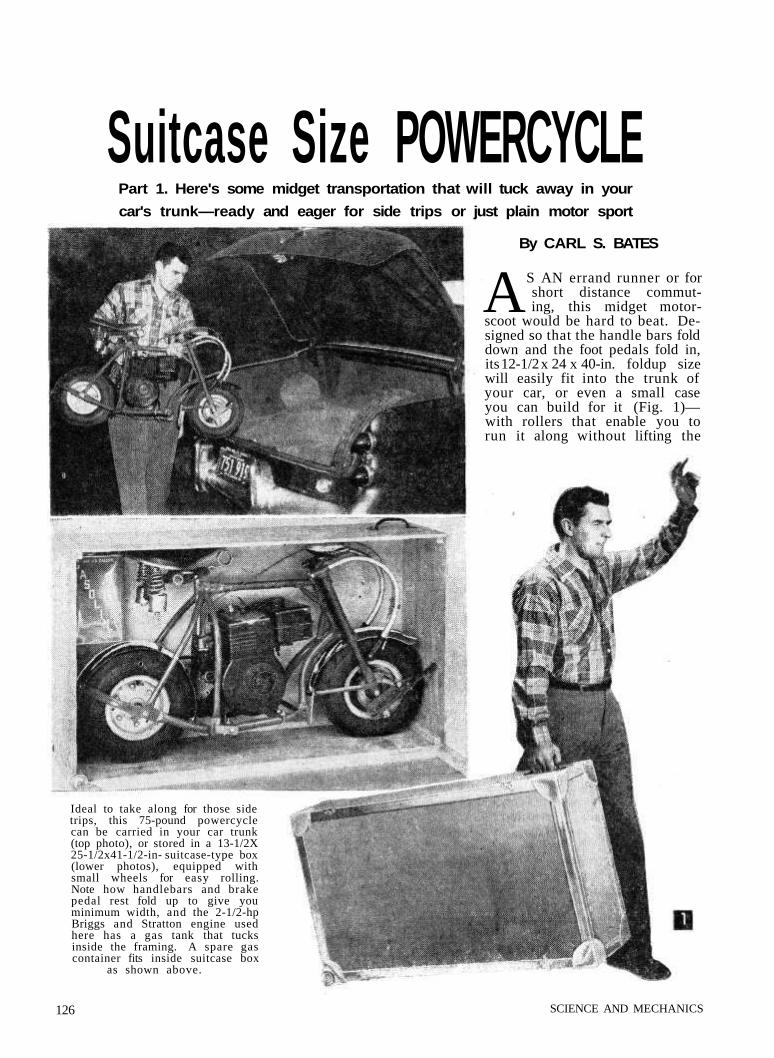
Suitcase Size POWERCYCLE Part 1. Here's some midget transportation that will tuck away in your car's trunk—ready and eager for side trips or just plain motor sport By CARL S. BATES A S AN errand runner or for short distance commut- ing, this midget motor- scoot would be hard to beat. De- signed so that the handle bars fold down and the foot pedals fold in, its 12-1/2 x 24 x 40-in. foldup size will easily fit into the trunk of your car, or even a small case you can build for it (Fig. 1)— with rollers that enable you to run it along without lifting the Ideal to take along for those side trips, this 75-pound powercycle can be carried in your car trunk (top photo), or stored in a 13-1/2X 25-1/2x41-1/2-in- suitcase-type box (lower photos), equipped with small wheels for easy rolling. Note how handlebars and brake pedal rest fold up to give you minimum width, and the 2-1/2-hp Briggs and Stratton engine used here has a gas tank that tucks inside the framing. A spare gas container fits inside suitcase box as shown above. 126 SCIENCE AND MECHANICS
-
Upload
zebratwo -
Category
Automotive
-
view
51 -
download
0
Transcript of 2532773 suitcase-powercycle v2
Suitcase Size POWERCYCLEPart 1. Here's some midget transportation that will tuck away in your
car's trunk—ready and eager for side trips or just plain motor sport
By CARL S. BATES
AS AN errand runner or forshort distance commut-ing, this midget motor-
scoot would be hard to beat. De-signed so that the handle bars folddown and the foot pedals fold in,its 12-1/2 x 24 x 40-in. foldup sizewill easily fit into the trunk ofyour car, or even a small caseyou can build for it (Fig. 1)—with rollers that enable you torun it along without lifting the
Ideal to take along for those sidetrips, this 75-pound powercyclecan be carried in your car trunk(top photo), or stored in a 13-1/2X25-1/2x41-1/2-in- suitcase-type box(lower photos), equipped withsmall wheels for easy rolling.Note how handlebars and brakepedal rest fold up to give youminimum width, and the 2-1/2-hpBriggs and Stratton engine usedhere has a gas tank that tucksinside the framing. A spare gascontainer fits inside suitcase box
as shown above.
126 SCIENCE AND MECHANICS

Craft Print ProjectNo. 215
FEBRUARY, 1955
Pretty 5 foot, 7 inch model tries out the midget power scoot. Highschoolers may find this an ideal form of transportation to-and-fromschool or for errand running. It requires a regular motor vehicle license.
127

Note clutch and rear wheel drive, and folded-up frontfoot rest. In Part 2, we will show you how to add ahand-operated rear wheel brake (not shown here) inaddition to the foot-powered front wheel brake, forthose states that require a brake on each wheel.
entire weight. Best news about this pint- sizepowercycle is its cost—about $100 for materials,and $10 to $15 for welding if you don't do thispart of the assembly yourself. Commercialpowercycles regularly sell for over $200 to $400,and we don't know of any domestic commercialmodel that folds up the way this fellow does.
The model shown here is powered by a 2-1/2 hpBriggs and Stratton engine and, to keep downcost and space displacement, uses an automaticclutch pulley (acting like a fluid drive) and nogear shift. The speed you will get out of thiscombination of course won't be sensational, noris any unit designed with such a low horse-power engine intended for winning hill climbs.But it should get you there and back with ease.
For compactness, a retrievable pull starter isrecommended, as opposed to either the ropetype (that's hard work, son) or the kick type(which would stick out too far for drivingcomfort).
Make the frame (Fig. 3) first. Thin-walledelectrical conduit (T.W.C.) is used for all frameparts. Start by laying out the frame membersfull-size on heavy paper or cardboard from thedimensions given in Fig. 2, or use the craftprints which show these frame pieces full size.Cut the straight piece (A in Fig. 2) and fit the
128 SCIENCE AND MECHANICS

129FEBRUARY, 1955
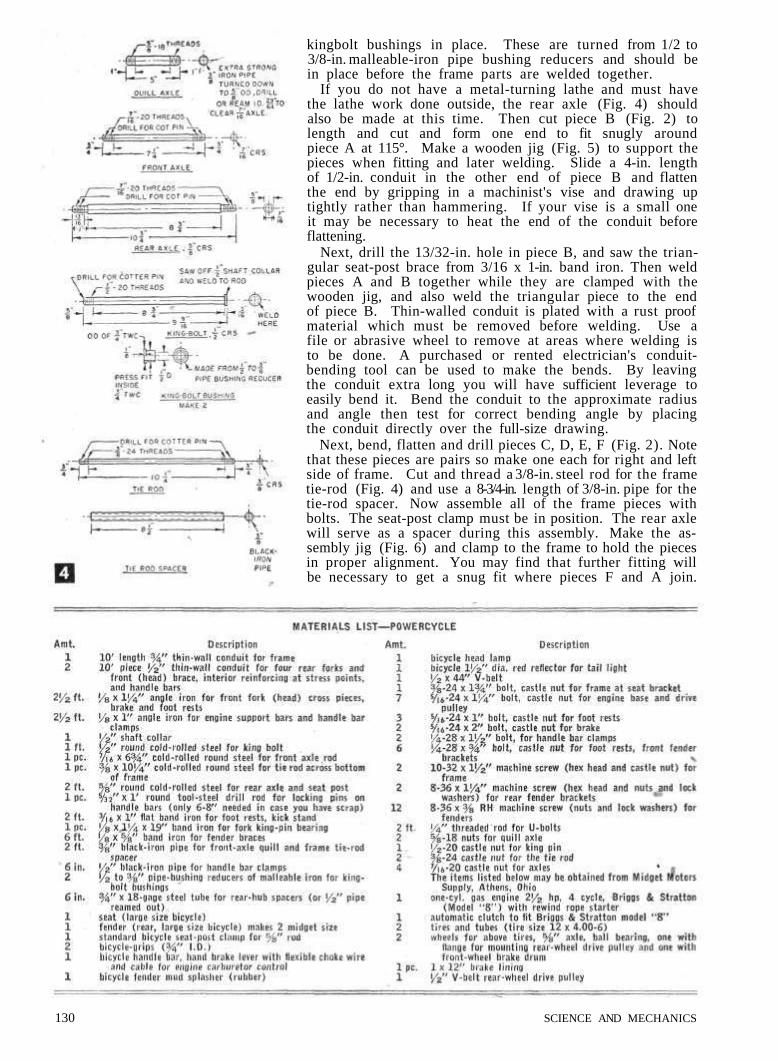
kingbolt bushings in place. These are turned from 1/2 to3/8-in. malleable-iron pipe bushing reducers and should bein place before the frame parts are welded together.
If you do not have a metal-turning lathe and must havethe lathe work done outside, the rear axle (Fig. 4) shouldalso be made at this time. Then cut piece B (Fig. 2) tolength and cut and form one end to fit snugly aroundpiece A at 115°. Make a wooden jig (Fig. 5) to support thepieces when fitting and later welding. Slide a 4-in. lengthof 1/2-in. conduit in the other end of piece B and flattenthe end by gripping in a machinist's vise and drawing uptightly rather than hammering. If your vise is a small oneit may be necessary to heat the end of the conduit beforeflattening.
Next, drill the 13/32-in. hole in piece B, and saw the trian-gular seat-post brace from 3/16 x 1-in. band iron. Then weldpieces A and B together while they are clamped with thewooden jig, and also weld the triangular piece to the endof piece B. Thin-walled conduit is plated with a rust proofmaterial which must be removed before welding. Use afile or abrasive wheel to remove at areas where welding isto be done. A purchased or rented electrician's conduit-bending tool can be used to make the bends. By leavingthe conduit extra long you will have sufficient leverage toeasily bend it. Bend the conduit to the approximate radiusand angle then test for correct bending angle by placingthe conduit directly over the full-size drawing.
Next, bend, flatten and drill pieces C, D, E, F (Fig. 2). Notethat these pieces are pairs so make one each for right and leftside of frame. Cut and thread a 3/8-in. steel rod for the frametie-rod (Fig. 4) and use a 8-3/4-in. length of 3/8-in. pipe for thetie-rod spacer. Now assemble all of the frame pieces withbolts. The seat-post clamp must be in position. The rear axlewill serve as a spacer during this assembly. Make the as-sembly jig (Fig. 6) and clamp to the frame to hold the piecesin proper alignment. You may find that further fitting willbe necessary to get a snug fit where pieces F and A join.
130 SCIENCE AND MECHANICS

Use a C-clamp to hold this joint together whenwelding. Cut, bend and fit brace G (Fig. 2) tothe assembled frame, and then weld in position.Also weld the conduit where pieces E and Fjoin, but do not weld to, the tie-rod or spacer.
If you do not have a welding outfit and musthave the welding done at your local job shop,make up the fork pieces (Figs. 2 and 7) beforehaving the frame welded so that all parts canbe welded at once. Cut two 19-1/2in. lengths of3/4-in. TWC ( H in Fig. 2) and two 8-in. lengthsof 1/2-in. TWC. Slide the 1/2-in. TWC into the3/4-in. TWC and flatten to 1/2 in for a distance of6 in. from one end. Lay out, drill and tap all theholes in pieces H. If possible, clamp the twopieces together when drilling so that the holesline up perfectly. Make the front axle andquill axle (Fig. 4) at this time so that they canbe used to clamp the fork parts together duringwelding. Cut the two angle-iron' pieces (J inFig. 7). Clamp both angle-iron pieces togetherwhen drilling so that the 15/16-in. holes will beequally spaced in both pieces. Unless you havea metal-turning lathe, have this drilling done atyour local machine shop. Also have two 2-in.lengths of 1/2-in. standard pipe bored or drilledout to take 1/2-in. TWC for handlebar clamps (Kin Fig. 3). Then cut the clamps lengthwise with ahacksaw. File a semi-circle in the top ends ofpieces H to take the handlebar clamps (Fig. 2).Make pieces L in Fig. 3 from 1 x 1-in. angle iron.Cut, bend and drill pieces M in Fig. 3 and bolt topieces J before welding . Then assemble pieces Hand J using C-clamps and fit it temporarily to theframe with the kingbolt to assure a closeand smooth turning action. Be sure that pieces
H and J are at right angles to each other beforewelding. Clamp and weld pieces K to each Hpiece and upper J piece with saw cuts to thecenter of the fork facing each other as shownin Fig. 3. Then position and weld pieces L. topieces K only. They are not welded to upper Jpiece. Drill 9/32-in. holes through pieces L and tapupper K piece 1/4-28 for 1/4-28 handle-bar clampbolts.
Now cut and bend the handle bars (N in Fig.2) and insert into clamps K. Tighten the 1/4-in. bolts until the handle bars can just forciblybe swung down or up. Do not drill the holesthrough pieces K and N for the locking pins Ountil the powercycle is completed because theexact driving position will vary somewhat de-pending upon the height of the rider.
Make and install the engine support bars (Pin Fig. 7) after the frame is welded. The U-bolts allow the engine to be moved forward orbackward for belt tension adjustment. Do notdrill the holes for mounting the engine untilthe drive pulley on the rear wheel is installed.Cut and bend the kick stand pieces Q and R asin Fig. 7. Tighten the 5/16-in. bolt and use a nutto lock and adjust the bolt tension so that pieceR will stay in the up or down position by fric-tion. Use a lock washer between pieces Q andR if necessary. Then bolt the kick stand unitto the frame with the rear right-hand, engine-support-bar U-bolt. Make the two frame fenderbrackets (Fig. 7) and bolt to the frame for therear fender, which will be installed later.
Part 2, appearing in the next issue, will showyou how to assemble the engine, drive belts,brakes, throttle controls and accessories.
FEBRUARY, 1955 131

Suitcase SizePOWERCYCLE
Believed to be thes m a l l e s t powercyclethat will comfortablycarry an adult, thisvehicle can be foldedup to lit into most car
trunks.
By CARL S. BATES
, PART 2
Craft Print Project No. 215
WHEN the powercycle frame is com-pletely assembled (part 1, S&M Feb-ruary, 1955), your next step is to in-
stall the rear-wheel assembly. Inasmuch asthis is a trial assembly for cutting and fittingthe parts to proper size, leave the rear fenderinstallation until later after the frame ispainted. The rear wheel mentioned in thematerials list, part 1, comes complete withflange and threaded lugs for mounting thedriven pulley and rear brake drum. Twodriven pulleys are available. A 9-in. dia. one which will givethe powercycle maximum pulling power for hilly streets andan 8-in. dia. pulley which "will give the powercycle the maxi-mum speed. In either case drill through the heads of the threepulley-mounting cap screws and wire as in Fig. 9 to preventtheir loosening and falling out. Cut the two rear-axle spacers(S in Fig. 9-A) from 3/4-in. O.D. x 18-gage steel tubing slightlyoversize and file ends until tubing spacers can just be turnedby hand when assembled with the rear wheel in the frameand axle nuts drawn up tight. The spacers merely keep the
. V.
A—Lever stop plate. B—Hand-brake lever. C—Drive pulley. D—Engine belt-guidebracket. E—Cable brackets. F—Clutch-control wire. G—Foot pedal. H—Spring.
J—Movable idle-pulley arm. K—Idle pulley. L—Driven pulley.
Left side of powercycle showing rear-wheel hand brake and foot-pedal operated idle-pulley type of clutch.
APRIL, 1955
wheel in position and must not put aload on the rear-wheel bearings. Itwill be necessary to remove the boltholding one side of the frame fender-bracket to spread part C of frame(Fig. 3, part 1) over the ends of therear axle. Place the drive belt on thedriven pulley before installing therear axle assembly in the frame. Usea 45-in. long 1/2-in. V-belt with a 9-in.dia. pulley and a 43-in. long 1/2-in.V-belt with an 8-in. dia. pulley.
Place the powercycle on a box andclamp down (Fig. 10) to facilitate
119

working on the machine. Then place the engineon the engine support bars. At this point youwill have to decide whether you are going to usethe automatic clutch and drive pulley or the foot-controlled belt-tightener type of drive clutch(Fig. 8). In either case place the pulley on theengine shaft as close to the engine as possibleand line up the drive pulley on the engine shaftwith the driven pulley on the rear wheel with ayardstick or straightedge (Fig. 11). Then markthe location of the four engine mounting boltholes on the engine support bars. Remove theengine and support bars and drill the 3/8-in. holesin the bars. Reassemble the support bar to theframe but do not tighten the U-bolt nuts becausethe position of the bars are determined by thelength and tension of the drive V-belt. The en-gine, however, can be mounted on the bars and
permanently bolted to the bars with 5/16-in. capscrews drilled for cotter pins.
If you decide upon the foot-controlled, belt-tightener type of clutch, weld a 1/8x1-1/2x1-1/2in.band-iron pad on the outside of both sides of thefork (H in Fig. 2, part 1) and drill and tap5/16-24 through the pad and fork tubing. Maketwo foot pedals (Fig. 12), one right and one left,and bolt in place on the fork. Use castle nuts
120 SCIENCE AND MECHANICS

and drill the cap screws for cotter pins. Tightenthe cap screws just enough to allow the footpedals to be moved up and down without anyplay. Grease the bearing surfaces.
To support the movable idle-pulley arm, layout, saw and bend the idle-pulley bracket (Fig.9-B) and fasten to the left side of the front en-gine support bar with the U-bolt (Fig. 9). Ifthe rear-wheel hand brake is to be included (re-quired by some states), you will save yourselfsome time by making the hand-brake bracket(Fig. 9-B) and installing it at the same time youbolt the idle-pulley bracket in place.
When working on front and rear wheel assemblies,place powercycle on a box and secure to top with
a C-clamp.
To make the movable idle-pulley arm, heat a3/8-in. dia. steel rod to make good sharp bends(Fig. 9-B). It may be necessary to file the bear-ing surfaces of the rod slightly as indicated, toseat the washers at right angles to the rod. Drillthe 3/32-in. hole for the control wire. Use two3/8-in. I.D. ball bearings (see materials list) forthe idle pulley and assemble with washers andcotter pins.
Make the two cable brackets (Fig. 9-B) andbolt in position. The cable control wire is alength of automobile choke wire cut to length sothat it will reach from the left foot pedal to themovable arm (Fig. 9). Allow enough slack sothat the control wire will not interfere with
APRIL, 1955 121

steering the front wheel. Be sure to bolt a belt-guide bracket to engine (Fig. 8) if the idle-pulley type of drive is used. This bracket willprevent the belt from being thrown off the en-gine pulley. Adjust the belt tension by sliding theengine support bars on the frame; then tightenthe U-bolts.
If the rear-wheel hand brake is to be included,make the parts de-tailed in Fig. 9-Band temporarilyinstall them (Fig.9) at this time. Besure to counter-sink the brake-band rivets. If youdo not have thetools to do this,have your localmotorcycle - repairshop mount thebrake-band lining.One addit ionalh o l e m u s t b edrilled throughthe rear enginesupport bar forthe brake anchorstrip. This can bemerely marked att h i s t i m e a n ddrilled later whenthe parts are dis-a s s e m b l e d forpainting. The rear-wheel b r a k e iscontrolled w i t hthe hand lever(Fig. 14). Use a straightedge to line up drive pulley
The front wheel on engine with driven pulley on rear axle.
mentioned in the materials list of Part 1 has thebrake drum welded on. Cut two spacers (Fig.12-A) 1 in. long from the 3/4-in. O.D. x 18-gagesteel tubing for the rear-axle spacers and file andfit so the total length of both spacers and wheelhub are exactly equal to or slightly less than thelength of the front quill axle previously made.This is important because the spacers must not
122 SCIENCE AND MECHANICS

bear against the ends of the front-wheel bearingbut only keep the wheel centered with the mini-mum amount of play.
Place the wheel, quill axle and spacers be-tween the fork (Fig. 12) and slide the front axlethrough the fork and quill and tighten. Makethe front brake band (Fig. 12-A), insert the5/16-in. bolts and assemble to the brake pedaland fork as shown in Figs. 12 and 13. Use aspring as indicated to keep the brake pedal inthe off position.
Now with the powercycle on the floor and theseat clamped in place, prop up the frame withblocks of wood to prevent it from falling over.Then mount the powercycle and assume a normalriding position with your feet on the front pedals.Move the handle bars up and down until theyare at the most comfortable driving position.Turn the front wheel from side to side as youwould when steering to make sure the handlebars clear your knees. When the handle barsare in the correct position for you, drill a 5/32-in.hole through the handle-bar clamps (N in Fig. 3,part 1) and the handle bars. Make two locking pins (Fig. 8)and insert in the drilled holes. To prevent the locking pinsfrom getting lost when the handle bars are in the folded-down position, tie the locking pins to the frame with a strongcord.
The carburetor-control assembly is next. Use an ordinarybicycle hand-brake lever on the right handle bar and anautomobile flexible choke cable and wire from the hand leverto the carburetor-valve lever (Fig. 14). A stronger springmust be used on the carburetor lever to assure smooth, en-gine-speed control.
With everything in working order, take the powercycle outfor a test run and make any minor adjustments necessary.When you are satisfied that everything is in good working
Right side of front wheel showing front-wheel brakeassembly.
A—Hand lever. B—Rear-wheel hand-brake lever. C—Carburetor-control wire.
Speed is controlled with hand-operated gas throttle level on theright handle bar.
APRIL, 1955 123
•«sfc»*^

order disassemble the powercycle and paint theframe, wheels, brackets and pedals. Use a metalundercoater first followed by two coats of auto-mobile enamel. The original powercycle frameis painted bright red, the wheels yellow and thehandle bars and hand-brake lever left the rust-proof metal finish.
While the paint is drying, make the front andrear fender brackets (Fig. 15). Both the frontand rear fenders are cut from one large-size,chrome-plated rear bicycle fender. After cutting,the fenders can be easily flattened somewhat tomake them wide enough for the powercyclewheels. Drill and bolt the fenders to the frame,using lock washers on all bolts to prevent loosen-ing due to vibration. Fasten a rubber bicyclemud splasher to the front fender and an 1-1/2-in.dia. red reflector on the rear fender for a taillight. If the powercycle is to be used at night,a battery-powered bicycle head lamp should befastened to the fork as shown. Although notnecessary, a sheet aluminum oval-shaped discwith the owner's initials painted on can be boltedto the front fork to give it that custom-built look.
You are now ready to make the final assembly.Carefully fit each part together to avoid scratch-ing the paint and be sure to use castle nuts andcotter pins on all of the cap screws. Use twonuts locked together on the engine support barU-bolts. Plans for the powercycle suitcase areshown in Fig. 16. Although the suitcase is notnecessary when carrying the powercycle in yourcar, it will come in handy for storage or trans-porting the powercycle by truck or train.—END
Whistling Car Motor• A whistling tea kettle may have a cheerfulsound, but a whistling car motor is just plainannoying. In such a case, check the bolts holdingintake manifold to the engine. Tightening thesebolts will stop the whistling sound and improveengine performance.—CHARLES PATTI.
Rotating Seed Treating Machine
WELD at the points of contact a lengthof 3/4 inch pipe extending through holes
tapped diagonally in each head of an oil drum.Two sections of 3/4 inch shafting, 6 and 4-inches long, are welded into the pipe.
A door fits over a 14-inch by 12-inch open-ing, with butt hinges and a 2-inch bolt weld-ed on opposite sides. Door is made dust-tightby welding on the drum a piece of angle iron,1 by 1 by 1/4 inches, with a gap cut in oneside. Frame is of 1 inch pipe, welded. Legsare 3 feet long and are braced with 3/4 inchpipe welded to the legs.
All welding was accomplished with 1/8 inchmild steel shielded arc electrode with themachine set at 120 amperes. A 12-inch V-pulley is attached to the shaft, and a 1/3horsepower electric motor is mounted on afloating base. With the fitting of belts, themachine is ready for operation. (Data andillustrations are from award paper by JamesD. Carter in The James F. Lincoln Arc Weld-ing Foundation's Agriculture and ScholarshipProgram).
124 SCIENCE AND MECHANICS

Fun In the ParkThe enclosed picture shows your powercycle
(Craft print 215) with my 7-year-old son Tomastride. He and other children sure do enjoy
Cont.
riding the cycle, which they do in a park. Itis also a must with the adults and I sure hada lot of fun building it.32 May Street ANTHONY ROGERSFall River, Massachusetts
It's hard not to have fun with that cycle, Tony.
Worth an "A" GradeDecided to use your
plans for building a suit-case size powercycle(Craft Print 215) for aForging and Weldingcourse in which I am en-rolled at Bowling GreenState University, Bowl-ing Green, Ohio. I start-ed production on thechallenging project Feb-ruary 10,1958 and had itcompleted by April 14,1958. It only took menine weeks of class time!
I used a 2-3/4 hp Briggsand Stratton engine witha 2-in. centrifugal clutchpulley on the motor anda 9-in. pulley on the rearwheel. This combinationgives me a top speed of33 mph. The pick-up isgood, and it climbsgrades exceptionallywell, and attracts moreattention here than aCadillac convertible. Thelights are powered by agenerator which oper-ates off the rear wheel. Imounted both the foot-
operated front wheel brake and the hand-operat-ed rear wheel brake. Great job on your cycle.
SCIENCE AND MECHANICS
Jack-Shaft for Those HillsHere's a power-
cycle that I builtfrom your CraftPrint 215. I fol-lowed the plans,but I also added ajack-shaft to geardown the motorso it has power toclimb the hi l lswhere I live. Ihave an automat-ic clutch with abelt to the jack-shaft, and fromthe jack-shaft tothe wheel I useda chain drive. Thisprevents a max-
imum of slippage. I am very pleased with itsperformance, and I have only you folks to thank.243 Hamilton Road BART CAKLSON
Chappaqua, New YorkA nice job of adapting the plans to fit your
needs, Bart. Of course, where there's no hillproblem, leaving off the jack-shaft, chain-drivearrangement will permit more speed.