2532771 power cycle-with-sidecar
7
23 POWERCYCLE with detachable carrying cart By JOE McBRIDE T HIS animated short snorter will barrel you along at 35 mph. When the fun's over, you can tuck it into your car or boat with ease. Lifting is no problem; it weighs only 55 pounds. When equipped with the detachable side cart (Fig. 2), the scooter b e c o m e s a practical package car- rier for shopping or special delivery serv- ice, or a tool carrier for farm and field servicemen. With some alteration in size and shape the same meth- od of building and at- taching this cart can be applied to adding a side cart to any power scooter. Although we used a 2-stroke cycle Clinton A400 engine, almost any 2- or 4-stroke cycle engine having a maximum of 2-1/2 hp could be used. The lightweight, vertical cylinder, horizontal shaft, 4-cycle engines, such as the Clinton A2100 or Briggs and Stratton 6B or 6B-5, offer some advantages over the 2-cycles in that they can be throttled down to run smoothly at slow speeds, are easier to start and do not require mixing of oil with the gas. Do not, however, use any of the heavy cast iron engines since their additional weight located off center on this small powercycle tend to make steering difficult and erratic. So then, you'll have transportation for your- self (Fig. 1) plus load carrying capacity with this little side-cart equipped powercycle, and the cart (Fig. 2) can be detached in the time it takes you to loosen three bolts. Since the shape and size of the frame mem- bers must be determined by the size of other matching parts, have on hand all of the parts given in the Materials List before starting actual construction. Making the Cycle Frame. Begin by hacksaw- Speeding along on the powercycle at 35 miles per hour, side cart not attached. ing the Chevrolet propellor shaft to length as given in Fig. 5A. Chuck, or tack-weld a block on the tube end of the shaft for a center, and mount the prop shaft in a metal- turning lathe. The lathe will have to have a 3-ft. between-centers capacity. If you do not have a lathe to do the work yourself, it will pay you to have the front fork (Fig. 6A) ready for machining, too, so that you can have all of the lathe work needed to build this cycle done at one time. The front fork is made from a Mercury sway bar which is heat-treated spring steel and may be a little too hard for sawing and machining without first annealing. To an- neal the bar, heat it to a dull red and allow it to cool slowly. You can do this with an acetylene torch or, better still, if there is an automobile spring shop or heat treating firm in your area, have them heat the entire bar in their furnace. After machining the front and rear axles, assemble the wheels on them to make cer- tain everything fits well. Then lay out and cut the two bending templates from sheet
-
Upload
zebratwo -
Category
Automotive
-
view
34 -
download
3
Transcript of 2532771 power cycle-with-sidecar

23
POWERCYCLEwith detachablecarrying cartBy JOE McBRIDE
THIS animated shortsnorter wil l barrelyou along at 35
mph. When the fun'sover, you can tuck itinto your car or boatwith ease. Lifting is noproblem; it weighsonly 55 pounds.
When equipped withthe detachable sidecart (Fig. 2), thescooter b e c o m e s apractical package car-rier for shopping orspecial delivery serv-ice, or a tool carrierfor farm and fieldservicemen. With somealteration in size andshape the same meth-od of building and at-taching this cart canbe applied to adding aside cart to any powerscooter.
Although we used a 2-stroke cycle ClintonA400 engine, almost any 2- or 4-stroke cycleengine having a maximum of 2-1/2 hp couldbe used. The lightweight, vertical cylinder,horizontal shaft, 4-cycle engines, such as theClinton A2100 or Briggs and Stratton 6B or6B-5, offer some advantages over the 2-cyclesin that they can be throttled down to runsmoothly at slow speeds, are easier to startand do not require mixing of oil with the gas.Do not, however, use any of the heavy castiron engines since their additional weightlocated off center on this small powercycletend to make steering difficult and erratic.
So then, you'll have transportation for your-self (Fig. 1) plus load carrying capacity withthis little side-cart equipped powercycle, andthe cart (Fig. 2) can be detached in the timeit takes you to loosen three bolts.
Since the shape and size of the frame mem-bers must be determined by the size of othermatching parts, have on hand all of the partsgiven in the Materials List before startingactual construction.
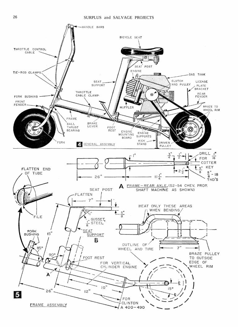
Making the Cycle Frame. Begin by hacksaw-
Speeding along on the powercycle at 35 miles per hour, side cart not attached.
ing the Chevrolet propellor shaft to lengthas given in Fig. 5A. Chuck, or tack-weld ablock on the tube end of the shaft for acenter, and mount the prop shaft in a metal-turning lathe. The lathe wil l have to have a3-ft. between-centers capacity.
If you do not have a lathe to do the workyourself, it wil l pay you to have the frontfork (Fig. 6A) ready for machining, too, sothat you can have all of the lathe workneeded to build this cycle done at one time.
The front fork is made from a Mercurysway bar which is heat-treated spring steeland may be a little too hard for sawing andmachining without first annealing. To an-neal the bar, heat it to a dull red and allowit to cool slowly. You can do this with anacetylene torch or, better still, if there is anautomobile spring shop or heat treating firmin your area, have them heat the entire barin their furnace.
After machining the front and rear axles,assemble the wheels on them to make cer-tain everything fits well. Then lay out andcut the two bending templates from sheet

24 SURPLUS and SALVAGE PROJECTS
metal as in Fig. 5. When bending the rearaxle and front fork, grip the stock in a viseand use an acetylene torch to heat just thoseareas of the stock that you are bending. Heatto a bright red and do not hold the torch toolong or too close at one spot. If the metalstarts to sparkle, it indicates it is burning andis too hot. Do not quench wi th water to coolbut allow to cool slowly to room temperature.
An 18-in. length of 1//2-in. black iron pipewi th one end dri l led out to 5/8 in. (so that itcan be slipped over the ends turned down forthe axles) w i l l protect the machined surfacesand give you the leverage needed for bend-ing. Use the bending templates to check theamount and angle of the bends occasionally.Final accuracy of bend must be checked bymounting the wheels w i th tires. Wheelcenters must be in line wi th centerlines ofshafts and have clearance for tires. A l lowspace for installation of fender on front fork.Note that the front fork has a secondarybend, other than those shown on the template,of 2 in. forward for wheel caster effect. Therear axle arm is bent 15° from centerline oftube as in frame assembly drawing Fig. 5.
Cut the fork bushing (Fig. 6B) from 1/2-in.pipe and run a 5/8-in. dr i l l through it to clean
up the inside so that the bushing w i l l slideon the turned portion of the front fork.
Then flatten the end of the frame tube ( A ) ,and file the top and bottom edges of the tubehalf-round to take the fork bushing at 85°as in the frame assembly drawing Fig. 5.After welding the bushing to the frame, againdr i l l it out because the heat of welding mayhave distorted it somewhat.
Use the cut-off piece of prop shaft tubingfor the seat support (Fig. 5B). Grind or filethe end of the support to fit t ightly againstthe frame tube. This operation, which is com-monly called "fishmouthing" the end of atube, w i l l make welding a lot easier becauseyou w i l l not have gaps to fill. If you aregoing to use a Clinton engine as we did, weldthe seat support to frame A, locating its cen-ter 12 in. from the rear end of the frame tubeas in the frame assembly, Fig. 5. If you aregoing to use a Briggs and Stratton aluminumvertical cylinder engine, locate the seat sup-port 10 in. from the rear end of the frametube. Then heat and bend the foot rest (C inFig. 6), and weld it to the frame tube right inback of the seat support.
To determine the angle at which the re-maining parts are welded to the frame, tern-

SURPLUS and SALVAGE PROJECTS
Small passengers only; and give them a cautious ride.
porarily assemble the front and rear wheelson their axles. Then slide the ball thrustbearing on the front fork and insert the forkthrough the fork bushing on the frame. Placeone tie-rod clamp at the top of the fork bush-ing over the saw slot and another clampabove it on front fork shaft (Fig. 4).
To support the cycle and keep it in an up-right position while you work on it, make upa wooden stand from scrap 1 x 4-in. stockas in Fig. 2A. Place the stand under the footrest, and weld the seat post to the top of theseat support so that it is parallel with thefloor. Hacksaw the gusset from a piece of1/8 x 1-in. strip steel and weld it to the cornerwhere the seat post joins the seat support asin the frame assembly Fig. 5. If you are us-ing the vertical cylinder engine with the seatsupport located closer to the rear, you wil lnot need the gusset and wil l need a seat postonly 5 in. long.
Engine Installation. While you are at the autowrecking yards have the yard man cut youthe two engine supports (Fig. 7A) with anacetylene torch. To save time at the yards,make up paper patterns of the engine sup-ports and have them ready so that you canplace them on an old car frame channel anddraw around them with chalk. Have the yardman cut off a 2 x 2-1/2-in. piece of 1/8-in. thicksteel for the brake, too. Grind smooth therough-cut edges of the engine supports and
weld them to the frame as in Figs. 4 and 7A.Reinforce the rear engine support with 1/4-in.steel rods welded in place.
The best V-belt pulley to use for the rearwheel is a 7-in. dia. water pump pulley froma Chevy, Olds, or Buick because it has anoffset center which provides clearance forthe tire. Cut out the center of the pulley andbraze it to the rim of the rear wheel at fourplaces as in Fig 4. Then reassemble the wheeland mount it on rear axle with nut and pin.
Now, with a V-Plex automatic clutch onthe engine drive shaft, place the plywood andengine on the engine supports as in Fig. 4.Line up the V-belt pulley on the engine withthe one on the rear wheel and measure thesize V-belt needed. After purchasing the belt,place it on the pulleys and mark the locationof the engine mounting holes on the enginesupports. Dri l l these holes 3/8-in. and bolt theengine in place. To take up belt stretch later,a piece of plywood 1/4 to 3/4-in. thick may beplaced under the engine base as in Fig. 4.
The performance of the Clinton A400 en-gine can be improved by opening up thebaffle plates inside the muffler (A in Fig. 9).Weld the exhaust holes closed and for a newexhaust opening, weld a 3-in. length of 3/4-in.conduit to the muffler. If you are going touse the side car on the cycle, weld another3-in. length of conduit to the exhaust openingas in the side view Fig. 9 to direct the hot
26 SURPLUS and SALVAGE PROJECTS

gasses away f rom the side of the car.Handle Bars. Make the handle bars f r om a
'48 Ford t ie rod, bending and weld ing themas in Fig. 7B. Weld a 3/8 x 2-1/2-in. cap screwto the r ighthand side of the handle bar formount ing the throt t le control handle (madef rom 3/4-in. conduit as in Fig. 7B) . Weld thethrott le-cable support to the underside of thehandle bar and slide the cable through it .Thread or spot braze the end of the cable tothe support ing 3/8-in. nut . The w i re inside thecontrol cable is fastened to the swivel clampbolted to the conduit handle. Run the cableback along the cycle frame and connect it tothe carburetor throt t le lever. Disconnect andremove the engine governor l inkage, andchange the lever (B in Fig. 9) .
Fenders are required by law in some statesfor licensed scooters. We made ours f rom
pieces of car body sheet metal wh ich is softand can be easily cut and bent to the shapesshown in Fig. 8.
Brake. Be sure to use 1/2-in. round, waterhardening tool steel for the brake lever be-cause ordinary cold-rol led m i l d steel maybend out of shape and leave you w i thou tbrakes. Make the brake as detailed in Fig.7C and mount it on a 1/2 x 3-in. cap screwwelded to underside of the frame as in brakeassembly Fig. 6. D r i l l the threads out of the1/2-in. hex nut welded to the foot brake sothat the nut w i l l slide on the cap screw. Thenr u n a 1/2-in. hex nut on the cap screw to re-ta in the brake lever. This same nu t is usedfor the k ick stand, too. Be sure the nu t ison the cap screw before weld ing the k ickstand (Fig. 6D) to i t because i t wou ld beimpossible to instal l the k ick stand other-
SURPLUS and SALVAGE PROJECTS 27

28 SURPLUS and SALVAGE PROJECTS
wise. The nut must also have enough threaddrag or fr ict ion to hold the kick stand inthe up position. If the nut is too loose, col-lapse it slightly by squeezing in a vise beforeinstalling it.
With the exception of lights and a horn,required by some states before you can geta scooter license, your powercycle should becomplete and ready for a test run. The horncan be the rubber bulb type available at autoparts and dime stores. The lights (head lightand tai l l ight) can be operated by a #6 drycell battery or the type used for bicycles.
Side Cart. The best procedure to follow inmaking and assembling the side cart to thepowercycle you have bui l t is to cut and fitthe four cart frame pieces (Fig. 2) individu-ally. Start by making the axle extensionfrom a 20-1/2-in. length of 1/2-in. i ron pipe.Weld a 5/8 x 2-1/2-in. cap screw on one end,and heat and flatten the other end. Make upthree cart attachment lugs as in Fig. 2B andbolt one to the flattened end of the axle ex-tension. Then, w i th the wheel mounted onthe axle extension and the cycle blocked inthe upright position on the floor, place thelug end of the axle extension against the
rear axle arm of the cycle as in Fig. 2. Cuta couple of 2 x 2 in. blocks to hold the axleextension level wi th the floor and at r ightangles to the cycle frame. If you are doingyour own welding, tack-weld the lug to therear axle arm of the cycle. Otherwise, clampor wire the lug to the arm.
Caution: Welding near a gasoline tank canbe dangerous business. Be sure to drain gaso-line from engine gas tank and carburetor andblow out tank before welding, or better stil l,remove the engine from the cycle.
Next, make cart frame part X in Fig. 2.Bend and fit the end that is fastened to theaxle extension first. Then bend, cut and flat-ten the end to be attached to the cycle framewi th a lug as in Fig. 2C. Use blocks to holdpart X level wi th the floor and tack-weld ortemporarily wire the lug to the cycle frame.
Now cut and fit part Y in position, tack-welding or taping it wi th plastic electrician'stape to hold it in place. Follow by fittingpart Z in place, fastening the end to the cycleseat support wi th a lug. Cut the triangularshaped pieces, which reinforce the cart frameand provide mounting-bolt holes for the cartbox, and weld them to the frame members.

SURPLUS and SALVAGE PROJECTS 29
Also complete al l the other welding of thelugs and cart frame joints whi le i t is s t i l lattached to the cycle to avoid d istor t ion ofthe parts due to heat of welding.
The cart box is made of 1/4-in exter ior p ly-wood reinforced w i t h cleats at al l inside cor-ners as detailed in F ig. 2D. Bol t i t to theframe w i t h three 1/4-in. fh bolts. Make thecart fender (F ig . 8) f rom sheet metal as you
did the cycle fenders, and bolt i t to the cartbox. Use Shake-proof nuts on the three boltsthat fasten the side cart to the cycle to pre-vent the nuts v ibrat ing loose.
Sets of plans for bu i ld ing the powercycleand side cart are available f rom the designerfor $2, ppd. Send check or money order, noC.O.D.'s or stamps, to Joe McBr ide, 2631Kensington Way, Stockton 4, Calif.