252 Programmable Controllers -...
16
251 Programmable Controllers C200H-TM001 CS1W-SF200 P207 Basic I/O Units Special I/O Units 96 pts Output Unit: CS1W-OD29@ 96 pts Input Unit: CS1W-ID291 16 pts Output Unit: CS1W-OD21@ 32 pts Output Unit: CS1W-OD23@ 64 pts Output Unit: CS1W-OD26@ 16 pts Input Unit: CS1W-ID211 32 pts Input Unit: CS1W-ID231 64 pts Input Unit: CS1W-ID261 32 inputs/32 outputs I/O Unit: CS1W-MD26@ 32 inputs/32 outputs TTL I/O Unit: CS1W-MD561 (available soon) 48 inputs/48 outputs I/O Unit: CS1W-MD29@/561 16 pts AC Input Unit: CS1W-IA111/211 8 pts Triac Output Unit: CS1W-OA201 16 pts Triac Output Unit: CS1W-OA211 8 pts (independent) Relay Output Unit: CS1W-OC201 16 pts Relay Output Unit: CS1W-OC211 Note: C200H Basic I/O Units and High-density I/O (Group-2) Units can also be used. Interrupt function supported on CPU Rack only. (Two Units mountable on CPU Rack.) 16 pts CS1W-INT01 16 pts C200H-B7AI1/O1 Group-2 Unit C200H-B7A 02/12/21/22 16 pts CS1W-IDP01 Process I/O Unit CS1W-P@@@(-V1) Temperature Sensor Units C200H-TS@@@ Temperature Control Units C200H-TC@@@ C200H-TV@@@ PID Control Units C200H-PID0@ Position Control Units* C200HW-NC@@@ CAN(open) Unit C200HW- CORT21-V1 PROFIBUS-DP Master Unit C200HW-PRM21 PROFIBUS-DP I/O Link Unit C200HW-PRT21 Position Control Unit CS1W-NC@@@ 2-axis Motion Control Unit* C200H-MC221 4-axis Motion Control Unit* C200H-MC402E Cam Positioner Unit* C200H-CP114 ID Sensor Units* C200H-IDS@@ ASCII Units* C200H-ASC@@ GP-IB Interface Unit CS1W-GPI01 DeviceNet I/O Link Unit C200HW-DRT21 CompoBus/S Master Unit C200HW-SRM21-V1 High-speed Counter Units* C200H-CT@@@ Analog Input Unit CS1W-AD041-V1 /081-V1 Analog Output Unit CS1W-DA041/ 08V/08C Analog I/O Unit CS1W-MAD44 Motion Control Unit CS1W-MC221/421 High-speed Counter Unit CS1W-CT021/041 SSI input unit CS1W-CTS21 Customizable Counter Units CS1W-HCP22-V1/ HCA22-V1/ HCA12-V1/ HIO01-V1 The following restrictions exist in data transfers with the CPU Unit for bit and DM Area specifications for the C200H Special I/O Units marked with asterisks, as well as in data transfers programmed from these Units. Refer to CS-series PLC Operation manuals for details. • Converting data for the CPU Unit using bit and DM Area specifications (source/destination area type and addresss designation). • Exchanging data with the CPU Unit using instructions (PC READ, PC WRITE, etc.) in the C200H Special I/O Unit program. Note: HMC-172/372/672 Memory Cards cannot be used with CS1G-CPU@@H, CS1H-CPU@@H, CJ1G-CPU@@H, or CJ1H-CPU@@H CPU Units prior to Lot No. 02108 (manufactured prior to January 8, 2002, nor with NS-7-series PTs prior to Lot. No. 0852 (manufactured prior to May 8, 2002). Check lot numbers before ordering. CS1 Special I/O Unit C200H Basic I/O Unit Interrupt Input Unit Analog Timer Unit B7A Interface Units High-speed Input Unit Safety Relay Unit C200H Special I/O Unit ID Sensor Units* CS1W-V600C11/ -V600C12
Transcript of 252 Programmable Controllers -...

251
Pro
gra
mm
able
C
on
tro
llers
C200H-TM001 CS1W-SF200
P207Basic I/O Units
Special I/O Units
96 ptsOutput Unit:CS1W-OD29@
96 ptsInput Unit:CS1W-ID291
16 ptsOutput Unit:CS1W-OD21@
32 ptsOutput Unit:CS1W-OD23@
64 ptsOutput Unit:CS1W-OD26@
16 ptsInput Unit:CS1W-ID211
32 ptsInput Unit:CS1W-ID231
64 ptsInput Unit:CS1W-ID261
32 inputs/32 outputsI/O Unit:CS1W-MD26@
32 inputs/32 outputsTTL I/O Unit:CS1W-MD561(available soon)
48 inputs/48 outputsI/O Unit:CS1W-MD29@/561
16 ptsAC Input Unit:CS1W-IA111/211
8 ptsTriac Output Unit:CS1W-OA201
16 ptsTriac Output Unit:CS1W-OA211
8 pts (independent)Relay Output Unit:CS1W-OC201
16 ptsRelay Output Unit:CS1W-OC211
Note: C200H Basic I/O Units and High-density I/O (Group-2) Units can also be used.
Interrupt functionsupported on CPURack only.(Two Unitsmountable onCPU Rack.)
16 ptsCS1W-INT01
16 ptsC200H-B7AI1/O1
Group-2 UnitC200H-B7A02/12/21/22
16 ptsCS1W-IDP01
Process I/O UnitCS1W-P@@@(-V1)
TemperatureSensor UnitsC200H-TS@@@
TemperatureControl UnitsC200H-TC@@@C200H-TV@@@
PID Control UnitsC200H-PID0@
Position Control Units*C200HW-NC@@@
CAN(open) UnitC200HW-CORT21-V1
PROFIBUS-DPMaster UnitC200HW-PRM21
PROFIBUS-DP I/O Link UnitC200HW-PRT21
Position Control UnitCS1W-NC@@@
2-axis Motion Control Unit*C200H-MC221
4-axis Motion Control Unit*C200H-MC402E
Cam Positioner Unit*C200H-CP114
ID Sensor Units*C200H-IDS@@
ASCII Units*C200H-ASC@@
GP-IB Interface UnitCS1W-GPI01
DeviceNet I/O Link UnitC200HW-DRT21
CompoBus/SMaster UnitC200HW-SRM21-V1
High-speedCounter Units*C200H-CT@@@
Analog Input UnitCS1W-AD041-V1/081-V1
Analog Output UnitCS1W-DA041/08V/08C
Analog I/O UnitCS1W-MAD44
Motion Control UnitCS1W-MC221/421
High-speed CounterUnitCS1W-CT021/041
SSI input unitCS1W-CTS21
CustomizableCounter UnitsCS1W-HCP22-V1/ HCA22-V1/ HCA12-V1/ HIO01-V1
The following restrictions exist in data transfers with the CPU Unit for bit and DM Area specifications for the C200H Special I/O Units marked with asterisks, as well as in data transfers programmed from these Units. Refer to CS-series PLC Operation manuals for details.
• Converting data for the CPU Unit using bit and DM Area specifications (source/destination area type and addresss designation).• Exchanging data with the CPU Unit using instructions (PC READ, PC WRITE, etc.) in the C200H Special I/O Unit program.
Note: HMC-172/372/672 Memory Cards cannot be used with CS1G-CPU@@H, CS1H-CPU@@H, CJ1G-CPU@@H, or CJ1H-CPU@@H CPU Units prior to Lot No. 02108 (manufactured priorto January 8, 2002, nor with NS-7-series PTs prior to Lot. No. 0852 (manufactured prior to May 8, 2002). Check lot numbers before ordering.
CS1 Special I/O Unit
C200H Basic I/O Unit
Interrupt Input Unit Analog Timer Unit B7A Interface Units High-speed Input Unit
Safety Relay Unit
C200H Special I/O Unit
ID Sensor Units*CS1W-V600C11/-V600C12

252 Programmable Controllers

253CS1-series
Pro
gra
mm
able
C
on
tro
llers
CS1H/G-CPU@@H
CS1-series
With the CS1 PLCs, Memory Cards and specified ranges of the EM Area can be used as file memory. File memory can be used to store the entire user program, I/O memory contents, and/or parameter area contents.
Note: Memory Card Adapter: HMC-AP001 (The Memory Card Adapter can be used to mount Memory Cards in PC card slots to use the Cards on a personal computer.)
Inner Board CompartmentAn Inner Board can be mounted here.
Peripheral Port
RS-232C Port
Indicators
Memory Card Indicators
Memory Card Power Supply Switch
Memory Card Eject Button
Memory Card Connector
Memory Card (See note.)
The MCPWR indicator lights green when power is being supplied. The BUSY indicator lights orange when the Memory Card is being accessed.
The Memory Card power supply switch is pressed to turn OFF power before removing the Memory Card.
Press the Memory Card eject button to remove the Memory Card.
The RS-232C port connects Peripheral Devices other than Programming Consoles, such as host computers, general-purpose external devices, and Program-mable Terminals.
The peripheral port connects Programming Devices, such as a Programming Console or host computer.
File memory Memory type Capacity ModelFlash memory 15 MB HMC-EF172
30 MB HMC-EF372
64 MB HMC-EF672
RAM EM Area capacity of CPU Unit (Max. capacity for CS1H-CPU67: 832 KB).
From the specified bank in the EM area of I/O memory to the last bank (specified in PC Setup).
Memory Cards
EM File Memory
EM areaBank 0Bank n
Bank C
EM File Memory

254 Programmable Controllers
Specifications
CPU Units
Note: The available data memory capacity is the sum of the Data Memory (DM) and the Extended Data Memory (EM).
Common Specifications
Note: A max. of 10 or 16 C200H Special I/O Units can be used depending on the CPU Unit. Some I/O Units are Special I/O Units.
Model I/O bits Program ca-pacity
Data memory ca-pacity (See Note.)
LD instruction pro-cessing speed
Built-in ports Options
CS1H-CPU67H 5,120 bits (Up to 7 Expansion Racks)
250 kSteps 448 kWords 0.02 µs Peripheral port and RS-232C port.
Memory CardsInner Board such as Serial Communications Board
CS1H-CPU66H 120 kSteps 256 kWordsCS1H-CPU65H 60 kSteps 128 kWordsCS1H-CPU64H 30 kSteps 64 kWordsCS1H-CPU63H 20 kStepsCS1G-CPU45H 5,120 bits
(Up to 7 Expansion Racks)60 kSteps 128 kWords 0.04 µs
CS1G-CPU44H 1,280 bits (Up to 3 Expansion Racks)
30 kSteps 64 kWords
CS1G-CPU43H 960 bits (Up to 2 Expansion Racks)
20 kStepsCS1G-CPU42H 10 kStepsCS1D-CPU65H 5,120 bits
(Up to 7 Expansion Racks)60 kSteps 128 kWords 0.02 µs
CS1D-CPU67H 250 kSteps 448 kWordsCS1D-CPU65D 5,120 bits
(Up to 7 Expansion Racks)60 kSteps 128 kWords Memory Cards
Duplex CPU with integrat-ed LCB05 Loop Control Board.
CS1D-CPU67D 250 kSteps 448 kWords
Item SpecificationControl method Stored programI/O control method Cyclic scan and immediate processingProgramming Ladder diagramInstruction length 1 to 7 steps per instructionLadder instructions Approx. 400 (3-digit function codes)Execution time Basic instructions: 0.02 µs min., Special instructions: 0.04 µs min.Number of tasks 288 (256 of which are also used as interrupt tasks)
Cyclic tasks are executed each cycle and are controlled with TKON(820) and TKOF(821) instructions.The following 4 types of interrupt tasks are supported: Power OFF tasks:1 max., Scheduled interrupt tasks: 2 max., I/O interrupt tasks: 32 max., External interrupt tasks: 256 max.
Interrupt types Scheduled Interrupts:Interrupts generated at a time scheduled by CPU Unit’s built-in timer.I/O Interrupts:Interrupts from Interrupt Input Units.Power OFF Interrupts:Interrupts executed when CPU Unit’s power is turned OFF.External I/O Interrupts:Interrupts from Special I/O Units, CS1 Special Units, or Inner Board.
CIO (Core I/O) Area(The CIO Area can be used as work bits if not used as shown here.)
I/O Area 5,120: CIO 000000 to CIO 031915 (320 words from CIO 0000 to CIO 0319)Setting of first rack words can be changed from default (CIO 0000) so that CIO 0000 to CIO 0999 can be used. I/O bits are allocated to Basic I/O Units, such as CS1 Basic I/O Units, C200H Basic I/O Units, and C200H Group-2 High-density I/O Units.
Link Area 3,200 (200 words): CIO 10000 to CIO 119915 (words CIO 1000 to CIO 1199)Link bits are used for data links and are allocated to Units in Controller Link Systems and PC Link Systems.
CS1 CPU Bus Unit Area
6,400 (400 words): CIO 150000 to CIO 189915 (words CIO 1500 to CIO 1899)CS1 CPU Bus Unit bits store operating status of CS1 CPU Bus Units. (25 words per Unit, 16 Units max.)
Special I/O Unit Area 15,360 (960 words): CIO 200000 to CIO 295915 (words CIO 2000 to CIO 2959)Special I/O Unit bits are allocated to CS1 Special I/O Units and C200H Special I/O Units. (See Note.)(10 words per Unit, 96 Units max.) The maximum number of slots, however, is limited to 80 including expansion slots, so maximum number of Units is actually 80.)Note: Some I/O Units are classified as Special I/O Units.
Inner Board Area 1,600 (100 words): CIO 190000 to CIO 199915 (words CIO 1900 to CIO 1999)Inner Board bits are allocated to Inner Boards. (100 I/O words max.)
SYSMAC BUS Area 800 (50 words): CIO 300000 to CIO 304915 (words CIO 3000 to CIO 3049)SYSMAC BUS bits are allocated to Slave Racks connected to SYSMAC BUS Remote I/O Master Units. (10 words per Rack, 5 Racks max.)
CS1-series 255
Pro
gra
mm
able
C
on
tro
llersItem Specification
CIO (Core I/O) Ar-ea, contd.(The CIO Area can be used as work bits if not used as shown here.)
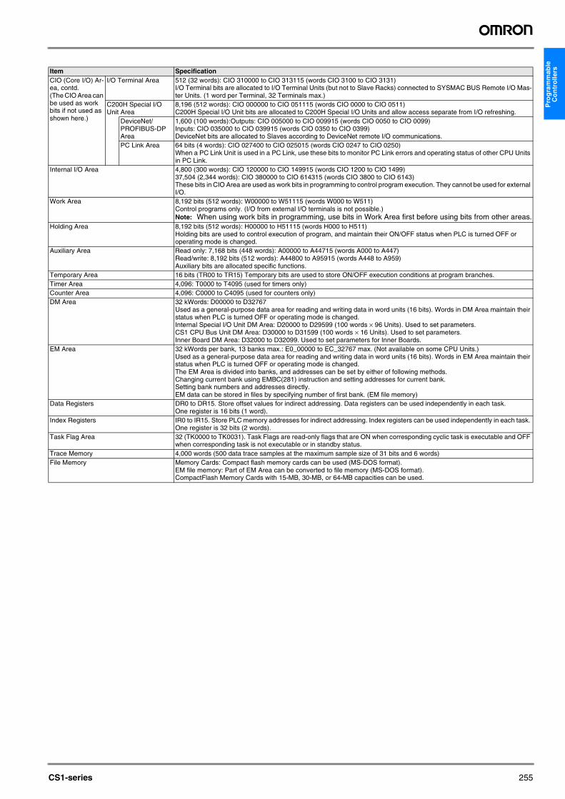
I/O Terminal Area 512 (32 words): CIO 310000 to CIO 313115 (words CIO 3100 to CIO 3131)I/O Terminal bits are allocated to I/O Terminal Units (but not to Slave Racks) connected to SYSMAC BUS Remote I/O Mas-ter Units. (1 word per Terminal, 32 Terminals max.)
C200H Special I/O Unit Area
8,196 (512 words): CIO 000000 to CIO 051115 (words CIO 0000 to CIO 0511)C200H Special I/O Unit bits are allocated to C200H Special I/O Units and allow access separate from I/O refreshing.
DeviceNet/PROFIBUS-DP Area
1,600 (100 words):Outputs: CIO 005000 to CIO 009915 (words CIO 0050 to CIO 0099)Inputs: CIO 035000 to CIO 039915 (words CIO 0350 to CIO 0399)DeviceNet bits are allocated to Slaves according to DeviceNet remote I/O communications.
PC Link Area 64 bits (4 words): CIO 027400 to CIO 025015 (words CIO 0247 to CIO 0250)When a PC Link Unit is used in a PC Link, use these bits to monitor PC Link errors and operating status of other CPU Units in PC Link.
Internal I/O Area 4,800 (300 words): CIO 120000 to CIO 149915 (words CIO 1200 to CIO 1499)37,504 (2,344 words): CIO 380000 to CIO 614315 (words CIO 3800 to CIO 6143)These bits in CIO Area are used as work bits in programming to control program execution. They cannot be used for external I/O.
Work Area 8,192 bits (512 words): W00000 to W51115 (words W000 to W511)Control programs only. (I/O from external I/O terminals is not possible.)Note: When using work bits in programming, use bits in Work Area first before using bits from other areas.
Holding Area 8,192 bits (512 words): H00000 to H51115 (words H000 to H511)Holding bits are used to control execution of program, and maintain their ON/OFF status when PLC is turned OFF or operating mode is changed.
Auxiliary Area Read only: 7,168 bits (448 words): A00000 to A44715 (words A000 to A447)Read/write: 8,192 bits (512 words): A44800 to A95915 (words A448 to A959)Auxiliary bits are allocated specific functions.
Temporary Area 16 bits (TR00 to TR15) Temporary bits are used to store ON/OFF execution conditions at program branches.Timer Area 4,096: T0000 to T4095 (used for timers only)Counter Area 4,096: C0000 to C4095 (used for counters only)DM Area 32 kWords: D00000 to D32767
Used as a general-purpose data area for reading and writing data in word units (16 bits). Words in DM Area maintain their status when PLC is turned OFF or operating mode is changed.Internal Special I/O Unit DM Area: D20000 to D29599 (100 words × 96 Units). Used to set parameters.CS1 CPU Bus Unit DM Area: D30000 to D31599 (100 words × 16 Units). Used to set parameters.Inner Board DM Area: D32000 to D32099. Used to set parameters for Inner Boards.
EM Area 32 kWords per bank, 13 banks max.: E0_00000 to EC_32767 max. (Not available on some CPU Units.)Used as a general-purpose data area for reading and writing data in word units (16 bits). Words in EM Area maintain their status when PLC is turned OFF or operating mode is changed.The EM Area is divided into banks, and addresses can be set by either of following methods.Changing current bank using EMBC(281) instruction and setting addresses for current bank.Setting bank numbers and addresses directly.EM data can be stored in files by specifying number of first bank. (EM file memory)
Data Registers DR0 to DR15. Store offset values for indirect addressing. Data registers can be used independently in each task. One register is 16 bits (1 word).
Index Registers IR0 to IR15. Store PLC memory addresses for indirect addressing. Index registers can be used independently in each task. One register is 32 bits (2 words).
Task Flag Area 32 (TK0000 to TK0031). Task Flags are read-only flags that are ON when corresponding cyclic task is executable and OFF when corresponding task is not executable or in standby status.
Trace Memory 4,000 words (500 data trace samples at the maximum sample size of 31 bits and 6 words)File Memory Memory Cards: Compact flash memory cards can be used (MS-DOS format).
EM file memory: Part of EM Area can be converted to file memory (MS-DOS format).CompactFlash Memory Cards with 15-MB, 30-MB, or 64-MB capacities can be used.

256 Programmable Controllers
Function Specifications
Item SpecificationParallel Processing Mode The program can be executed simultaneously with peripheral servicing (CS1G/CS1H only).Battery-free operation Flash memory is provided as a standard feature and automatically backs up the user program and system parameters.Constant cycle time 1 to 32,000 ms (Unit: 1 ms)Cycle time monitoring Possible (Unit stops operating if cycle is too long): 1 to 40,000 ms (Unit: 10 ms)I/O refreshing Cyclic refreshing, immediate refreshing, refreshing by IORF(097).I/O memory holding when changing oper-ating modes
Possible (Depends on ON/OFF status of IOM Hold Bit in Auxiliary Area.)
Load OFF All outputs on Output Units can be turned OFF.Input time constant setting Time constants can be set for inputs from CS1 Basic I/O Units. The time constant can be increased to reduce influence of
noise and chattering or it can be decreased to detect shorter pulses on inputs. (CS1 Basic I/O Units only)Mode setting at power-up PossibleMemory Card functions Automatic reading programs from Memory Card (autoboot).
Memory Card Storage DataUser program: Program file format (binary)PC System Setup: Data file format (binary)I/O Memory: Data file format (binary), text format, CSV formatMemory Card Read/WriteUser program instructions, Peripheral Devices (such as Programming Console), Host Link computer.
Filing Memory Card data and EM (Extended Data Memory) Area can be handled as files.Debugging Force-set/reset, differential monitoring, data tracing (scheduled, each cycle, or when instruction is executed), instruction error
tracing. Online editing One or more program blocks in user programs can be overwritten when CPU Unit is in PROGRAM or MONITOR mode.
This function is not available for block programming areas.Program protection Overwrite protection:Set using DIP switch.
Copy protection: Password set using Peripheral Device.Error check User-defined errors (i.e., user can define fatal errors and non-fatal errors)
The FPD(269) instruction can be used to check execution time and logic of each programming block.Error log Up to 20 errors are stored in error log. Information includes error code, error details, and time error occurred.Serial communications Built-in peripheral port: Peripheral Device (including Programming Console), Host Links, NT Links
Built-in RS-232C port: Peripheral Device (excluding Programming Console), Host Links, no-protocol communications, NT LinksCommunications Board (sold separately): Protocol macros, Host Links, NT Links
Clock Provided on all models.Note: Used to store time when power is turned ON and when errors occur.
Power OFF detection time 10 to 25 ms (not fixed)Power OFF detection delay time 0 to 10 ms (user-defined, default: 0 ms)Memory protection Held Areas: Holding bits, contents of Data Memory and Extended Data Memory, and status of counter Completion Flags and
present values.Note: If IOM Hold Bit in Auxiliary Area is turned ON, and PC Setup is set to maintain IOM Hold Bit status when power to
PLC is turnedl ON, contents of CIO Area, Work Area, part of Auxiliary Area, timer Completion Flag and PVs, Index Registers, and Data Registers will be saved.
Sending commands to a Host Link computer
FINS commands can be sent to a computer connected via Host Link System by executing Network Communications Instructions from PLC.
Remote programming and monitoring Host Link communications can be used for remote programming and remote monitoring through a Controller Link System or Ethernet network.
Three-level communications Host Link communications can be used for remote programming and remote monitoring from devices on networks up to two levels away (Controller Link Network, Ethernet Network, or other network).
Storing comments in CPU Unit I/O comments can be stored in CPU Unit in Memory Cards or EM file memory.Program check Program checks are performed at beginning of operation for items such as no END instruction and instruction errors.
A Peripheral Device (excluding Programming Console) can also be used to check programs.Control output signals RUN output: The contacts will turn ON (close) while CPU Unit is operating. These terminals are provided only on C200HW-
PA204R and C200HW-PA209R Power Supply Units.Battery life 5 years at 25°C (Depending on the ambient operating temperature and communications conditions, 1.1 years min. Battery
Set: CS1W-BAT01) Note: Use a replacement battery that is no more than 2 years old from the date of manufacture.
Self-diagnostics CPU errors (watchdog timer), I/O verification errors, I/O bus errors, memory errors, and battery errors.Other functions Storage of number of times power has been interrupted, the times of the interrupts, and system operation time (in Auxiliary
Area).
CS1-series 257
Pro
gra
mm
able
C
on
tro
llers
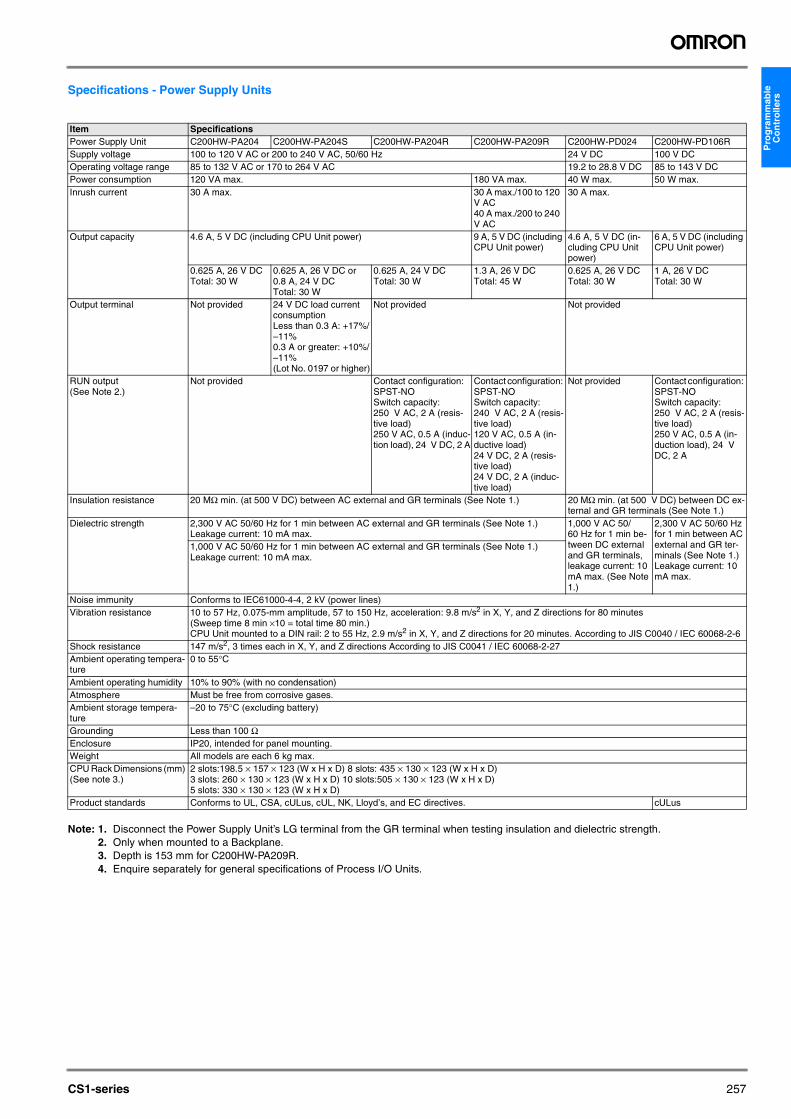
Specifications - Power Supply Units
Note: 1. Disconnect the Power Supply Unit’s LG terminal from the GR terminal when testing insulation and dielectric strength.2. Only when mounted to a Backplane.3. Depth is 153 mm for C200HW-PA209R.4. Enquire separately for general specifications of Process I/O Units.
Item SpecificationsPower Supply Unit C200HW-PA204 C200HW-PA204S C200HW-PA204R C200HW-PA209R C200HW-PD024 C200HW-PD106RSupply voltage 100 to 120 V AC or 200 to 240 V AC, 50/60 Hz 24 V DC 100 V DCOperating voltage range 85 to 132 V AC or 170 to 264 V AC 19.2 to 28.8 V DC 85 to 143 V DCPower consumption 120 VA max. 180 VA max. 40 W max. 50 W max.Inrush current 30 A max. 30 A max./100 to 120
V AC40 A max./200 to 240 V AC
30 A max.
Output capacity 4.6 A, 5 V DC (including CPU Unit power) 9 A, 5 V DC (including CPU Unit power)
4.6 A, 5 V DC (in-cluding CPU Unit power)
6 A, 5 V DC (including CPU Unit power)
0.625 A, 26 V DCTotal: 30 W
0.625 A, 26 V DC or 0.8 A, 24 V DCTotal: 30 W
0.625 A, 24 V DCTotal: 30 W
1.3 A, 26 V DCTotal: 45 W
0.625 A, 26 V DCTotal: 30 W
1 A, 26 V DCTotal: 30 W
Output terminal Not provided 24 V DC load current consumptionLess than 0.3 A: +17%/–11%0.3 A or greater: +10%/–11%(Lot No. 0197 or higher)
Not provided Not provided
RUN output (See Note 2.)
Not provided Contact configuration: SPST-NOSwitch capacity: 250 V AC, 2 A (resis-tive load)250 V AC, 0.5 A (induc-tion load), 24 V DC, 2 A
Contact configuration: SPST-NOSwitch capacity: 240 V AC, 2 A (resis-tive load)120 V AC, 0.5 A (in-ductive load)24 V DC, 2 A (resis-tive load)24 V DC, 2 A (induc-tive load)
Not provided Contact configuration: SPST-NOSwitch capacity: 250 V AC, 2 A (resis-tive load)250 V AC, 0.5 A (in-duction load), 24 V DC, 2 A
Insulation resistance 20 MΩ min. (at 500 V DC) between AC external and GR terminals (See Note 1.) 20 MΩ min. (at 500 V DC) between DC ex-ternal and GR terminals (See Note 1.)
Dielectric strength 2,300 V AC 50/60 Hz for 1 min between AC external and GR terminals (See Note 1.)Leakage current: 10 mA max.
1,000 V AC 50/60 Hz for 1 min be-tween DC external and GR terminals, leakage current: 10 mA max. (See Note 1.)
2,300 V AC 50/60 Hz for 1 min between AC external and GR ter-minals (See Note 1.)Leakage current: 10 mA max.
1,000 V AC 50/60 Hz for 1 min between AC external and GR terminals (See Note 1.)Leakage current: 10 mA max.
Noise immunity Conforms to IEC61000-4-4, 2 kV (power lines)Vibration resistance 10 to 57 Hz, 0.075-mm amplitude, 57 to 150 Hz, acceleration: 9.8 m/s2 in X, Y, and Z directions for 80 minutes
(Sweep time 8 min ×10 = total time 80 min.)CPU Unit mounted to a DIN rail: 2 to 55 Hz, 2.9 m/s2 in X, Y, and Z directions for 20 minutes. According to JIS C0040 / IEC 60068-2-6
Shock resistance 147 m/s2, 3 times each in X, Y, and Z directions According to JIS C0041 / IEC 60068-2-27Ambient operating tempera-ture
0 to 55°C
Ambient operating humidity 10% to 90% (with no condensation)Atmosphere Must be free from corrosive gases.Ambient storage tempera-ture
–20 to 75°C (excluding battery)
Grounding Less than 100 ΩEnclosure IP20, intended for panel mounting.Weight All models are each 6 kg max.CPU Rack Dimensions (mm) (See note 3.)
2 slots:198.5 × 157 × 123 (W x H x D) 8 slots: 435 × 130 × 123 (W x H x D) 3 slots: 260 × 130 × 123 (W x H x D) 10 slots:505 × 130 × 123 (W x H x D) 5 slots: 330 × 130 × 123 (W x H x D)
Product standards Conforms to UL, CSA, cULus, cUL, NK, Lloyd’s, and EC directives. cULus

258 Programmable Controllers
Specifications - Duplex Power Supply Units
Item SpecificationsPower Supply Unit CS1D-PA207R CS1D-PD024Supply voltage 100 to 120 V AC or 200 to 240 V AC, 50/60 Hz 24 V DCOperating voltage range 85 to 132 V AC or 170 to 264 V AC 19.2 to 28.8 V DCPower consumption 150 VA max. 40 W max.Inrush current 30 A max./100 to 120 V AC
40 A max./200 to 240 V AC30 A max.
Output capacity 7 A, 5 V DC (including CPU Unit power) 4.3 A, 5 V DC (including CPU Unit power)1.3 A, 26 V DCTotal: 35 W
0.56 A, 26 V DCTotal: 28 W
Output terminal Not provided Not providedRUN output (See Note 2.)
Contact configuration: SPST-NOSwitch capacity: 240 V AC, 2 A (resistive load)120 V AC, 0.5 A (inductive load)24 V DC, 2 A (resistive load)24 V DC, 2 A (inductive load)
Not provided
Insulation resistance 20 MΩ min. (at 500 V DC) between AC external and GR terminals (See Note 2.)
20 MΩ min. (at 500 V DC) between DC external and GR terminals (See Note 2.)
Dielectric strength 2,300 V AC 50/60 Hz for 1 min between AC external and GR ter-minals (See Note 2.)Leakage current: 10 mA max.
1,000 V AC 50/60 Hz for 1 min between DC external and GR termi-nals, leakage current: 10 mA max. (See Note 2.)
1,000 V AC 50/60 Hz for 1 min between AC external and GR ter-minals (See Note 1.)Leakage current: 10 mA max.
Noise immunity Conforms to IEC61000-4-4, 2 kV (power lines)Vibration resistance 10 to 57 Hz, 0.075-mm amplitude, 57 to 150 Hz, acceleration: 9.8 m/s2 in X, Y, and Z directions for 80 minutes
(Sweep time 8 min ×10 = total time 80 min.)CPU Unit mounted to a DIN rail: 2 to 55 Hz, 2.9 m/s2 in X, Y, and Z directions for 20 minutes. According to JIS C0040 / IEC 60068-2-6
Shock resistance 147 m/s2, 3 times each in X, Y, and Z directions According to JIS C0041 / IEC 60068-2-27Ambient operating tempera-ture
0 to 55°C
Ambient operating humidity 10% to 90% (with no condensation)Atmosphere Must be free from corrosive gases.Ambient storage tempera-ture
–20 to 75°C (excluding battery)
Grounding Less than 100 ΩEnclosure Mounted in a panel.Weight All models are each 6 kg max.

CS1-series 259
Pro
gra
mm
able
C
on
tro
llersBasic System Configuration
CPU RackA CPU Rack consists of a CPU Unit, Power Supply Unit, CPU Back-plane, Basic I/O Units, Special I/O Units, and CPU Bus Units. The Serial Communications Board and Memory Cards are optional.Note: The Backplane depends on the type of CPU Rack, Expansion I/
O Racks, and Slave Racks that are used.
Expansion RacksBoth C200H and CS1 Expansion Racks can be used.• C200H Expansion I/O Racks can be connected to CPU Racks, CS1
Expansion Racks, or other C200H Expansion I/O Racks.• CS1 Expansion Racks can be connected to CPU Racks or other
CS1 Expansion Racks. An Expansion Rack consists of a Power Supply Unit, a CS1 or C200H Expansion I/O Backplane, Basic I/O Units, Special I/O Units, and a CS1 CPU Bus Units.
Long-distance Expansion RacksAn I/O Control Unit and I/O Interface Units can be used to extend the normal limit of 12 m to 50 m for each of two series of CS1 Expansion Racks. The following Units can be mounted to Long-distance Expan-sion Racks: CS1 Basic I/O Units, CS1 Special I/O Units, and CS1 CPU Bus Units. (C200H Units cannot be mounted to Long-distance Expan-sion Racks.)
CPU Rack
Configuration
Products Used in CPU Racks
CPU RackCPU Backplane
Memory Card
I/O Connecting Cable
Expansion Rack
I/O Backplane
Remote I/O Master Unit
I/O UnitsSpecial I/O UnitsCS1 CPU Bus Units
Serial Communications Board
I/O UnitsSpecial I/O UnitsCS1 CPU Bus Units
Power SupplyUnit
Power SupplyUnit
Name Configuration RemarksCPU Backplane One of each Unit required for every CPU Rack.
Refer to the following table for model number.CPU UnitPower Supply UnitMemory Card Install as required.
Refer to the following table for model number.Serial Communications Board
Name Model SpecificationsCS1H-CPU67H I/O bits: 5,120, Program capacity: 250 kSteps
Data Memory: 448 kWords (DM: 32 kWords, EM: 32 kWords x 13 banks)CS1H-CPU66H I/O bits: 5,120, Program capacity: 120 kSteps
Data Memory: 256 kWords (DM: 32 kWords, EM: 32 kWords x 7 banks)CS1H-CPU65H I/O bits: 5,120, Program capacity: 60 kSteps
Data Memory: 128 kWords (DM: 32 kWords, EM: 32 kWords x 3 banks)CS1H-CPU64H I/O bits: 5,120, Program capacity: 30 kSteps
Data Memory: 64 kWords (DM: 32 kWords, EM: 32 kWords x 1 bank)CS1H-CPU63H I/O bits: 5,120, Program capacity: 20 kSteps
Data Memory: 32 kWords (DM: 32 kWords, EM: 32 kWords x 1 bank)CS1G-CPU45H I/O bits: 5,120, Program capacity: 60 kSteps
Data Memory: 128 kWords (DM: 32 kWords, EM: 32 kWords x 3 banks)CS1G-CPU44H I/O bits: 1,280, Program capacity: 30 kSteps
Data Memory: 64 kWords (DM: 32 kWords, EM: 32 kWords x 1 banks)CS1G-CPU43H I/O bits: 960, Program capacity: 20 kSteps
Data Memory: 64 kWords (DM: 32 kWords, EM: 32 kWords x 1 bank)CS1G-CPU42H I/O bits: 960, Program capacity: 10 kSteps
Data Memory: 64 kWords (DM: 32 kWords, EM: 32 kWords x 1 bank)CS1W-BC022 2 slots (Connection to Expansion Back-
plane is not possible.)These Backplanes are for CS1 Units only. Use CS1W-BC@@3 Backplanes if C200H Units are to be installed.CS1W-BC032 3 slots
CS1W-BC052 5 slotsCS1W-BC082 8 slotsCS1W-BC102 10 slots
CPU Rack
CPU Units
CPU Backplanes

260 Programmable Controllers
Expansion Racks
Expansion Rack Configuration
C200HW-PA204 100 to 120 V AC or 200 to 240 V AC, Output capacity: 4.6 A, 5 V DCC200HW-PA204S 100 to 120 V AC or 200 to 240 V AC (0.8 A 24 V DC service power)
Output capacity: 4.6 A, 5 V DCC200HW-PA204R 100 to 120 V AC or 200 to 240 V AC (with RUN output) Output capacity: 4.6 A, 5 V DCC200HW-PD024 24 V DC, Output capacity: 4.6 A, 5 V DCC200HW-PA209R 100 to 120 V AC or 200 to 240 V AC (with RUN output) Output capacity:
9 A, 5 V DC
I/O Control Unit CS1W-IC102 Connects to CS1 Expansion Racks (two Terminating Resistors included). Must be used together with I/O Interface Units to connect Long-distance Expansion Racks (50 m max.). Not required to connect CS1 Expansion Racks within 12 m.
HMC-EF172 Flash memory, 15 MBHMC-EF372 Flash memory, 30 MBHMC-EF672 Flash memory, 64 MBHMC-AP001 Memory Card adapter
Serial Communications Boards CS1W-SCB21 2 x RS-232C ports, protocol macro functionCS1W-SCB41 1 x RS-232C port + 1 x RS-422/485 port, protocol macro function
Programming Consoles CQM1-PRO01-E An English Keyboard Sheet (CS1W-KS001-E) is required.C200H-PRO27-E
Programming Console Connection Cables
CS1W-CN114 Connects the CQM1-PRO01-E Programming Console. (Length: 0.05 m)CS1W-CN224 Connects the C200H-PRO27-E Programming Console. (Length: 2.0 m)CS1W-CN624 Connects the C200H-PRO27-E Programming Console. (Length: 6.0 m)
CX-Programmer WS02-CXPC1-E-V## Windows-based Support Software for Windows 95/98/Me or Windows NT/2000/XP (check all occurrances of CX-software!9Note: Can connect through peripheral port or through RS-232C port on CPU Unit or
Serial Communications Board.
WS02-CXPC1-E-V##L03(For 3 licenses)WS02-CXPC1-E-V##L10(For 10 licenses)
Programming Device Connecting Cables (for peripheral port)
CS1W-CN118 Connects DOS computer, D-Sub 9-pin receptacle (Length: 0.1 m)CS1W-CN226 Connects DOS computer, D-Sub 9-pin (Length: 2.0 m)CS1W-CN626 Connects DOS computer, D-Sub 9-pin (Length: 6.0 m)XW2Z-200S-CV Connects DOS computer, D-Sub 9-pin (Length: 2.0 m)XW2Z-500S-CV Connects DOS computer, D-Sub 9-pin (Length: 5.0 m)
Programming Device Connecting Cable (for RS-232C port)
XW2Z-200S-V Connects DOS computer, D-Sub 9-pin (Length: 2.0 m) (For Host Link connection)XW2Z-500S-V Connects DOS computer, D-Sub 9-pin (Length: 5.0 m) (For Host Link connection)
CX-Simulator WS02-SIMC1-E Windows-based Support Software for Windows 95, 98, Me, 2000, NT, or XPNote: Simulates operation for CS1 CS1H/CS1G-CPU@@ CPU Units without “V1” at the
end of the model number.CX-Protocol WS02-PSTC1-E Windows-based Support Software for Windows 95, 98, Me, 2000 or NT
Used to create and manage protocol macros.Battery Set CS1W-BAT01 For CS1 Series only.
Note: Use a replacement battery that is no more than 2 years old from the date of manufacture.
Rack Configuration RemarksCS1 Expansion Rack CS1 Expansion I/O Backplane One of each Unit is required.
Power Supply UnitFor connection to a CPU Backplane or CS1 Expansion I/O Backplane: CS1 I/O Connecting CableFor connection to a C200H Expansion I/O Backplane: CS1 to C200H I/O Con-necting Cable
C200H Expansion I/O Rack C200H Expansion I/O Backplane One of each Unit is required.A CS1 Expansion Rack cannot be connected after a C200H Expansion I/O Rack.
Power Supply UnitFor connection to a CPU Backplane or CS1 Expansion I/O Backplane: CS1 to C200H I/O Connecting CableFor connection to a C200H Expansion I/O Backplane: C200H I/O Connecting Ca-ble
Name Model Specifications
Power Supply Units
Memory Cards

CS1-series 261
Pro
gra
mm
able
C
on
tro
llers
Products Used in Expansion Racks
Name Model Specifications Cable LengthCS1 Expansion I/O Back-planes
CS1W-BI032 3 slots These Backplanes are for CS1 Units only. Use CS1W-BI@@3 Backplanes if C200H Units are to be installed.
---CS1W-BI052 5 slotsCS1W-BI082 8 slotsCS1W-BI102 10 slots
C200H Expansion I/O Back-planes
C200HW-BI031 3 slotsC200HW-BI051 5 slotsC200HW-BI081-V1 8 slotsC200HW-BI101-V1 10 slots
Power Supply Units C200HW-PA204 100 to 120 V AC or 200 to 240 V ACOutput capacity: 4.6 A, 5 V DC
C200HW-PA204S 100 to 120 V AC or 200 to 240 V AC (with power output terminal: 0.8 A, 24 V DC)Output capacity: 4.6 A, 5 V DC
C200HW-PA204R 100 to 120 V AC or 200 to 240 V AC (with RUN output)Output capacity: 4.6 A, 5 V DC
C200HW-PA209R 100 to 120 V AC or 200 to 240 V AC (with RUN output)Output capacity: 9 A, 5 V DC
C200HW-PD024 24 V DCI/O Interface Unit CS1W-II102 Connects CS1 Expansion Racks. Must be used together with I/O Control
Unit to connect Long-distance Expansion Racks (50 m max.). Not required to connect CS1 Expansion Racks within 12 m.
---
CS1 I/O Connecting Cables
CS1W-CN313 0.3 m
CS1W-CN713 0.7 m
CS1W-CN223 2 m
CS1W-CN323 3 m
CS1W-CN523 5 m
CS1W-CN133 10 m
CS1W-CN133-B2 12 m
Long-distance Connecting Cables
CV500-CN312 For Long-distance Expansion RacksConnects the I/O Control Unit to I/O Interface Units or connects one I/O In-terface Unit to the next I/O Interface Unit.
0.3 mCV500-CN612 0.6 mCV500-CN122 1 mCV500-CN222 2 mCV500-CN322 3 mCV500-CN522 5 mCV500-CN132 10 mCV500-CN232 20 mCV500-CN332 30 mCV500-CN432 40 mCV500-CN532 50 m
CS1-C200H I/O Connecting Cables
CS1W-CN311 Connects C200H Expansion I/O Backplanes to CPU Backplanes or CS1 Ex-pansion I/O Backplanes.
0.3 mCS1W-CN711 0.7 mCS1W-CN221 2 mCS1W-CN321 3 mCS1W-CN521 5 mCS1W-CN131 10 mCS1W-CN131-B2 12 m
C200H I/O Connecting Cables
C200H-CN311 Connects C200H Expansion I/O Backplanes to other C200H Expansion I/O Backplanes.
0.3 mC200H-CN711 0.7 mC200H-CN221 2 mC200H-CN521 5 mC200H-CN131 10 m
@ @ @ @Reading the production number
Year (e.g., 1997=7)
Day (01 to 31)
Month (1 to 9, X (10), Y (11), Z (12))
Connects CS1 Expansion I/O Backplanes to CPU Backplanes or other CS1 Expansion I/O Backplanes.
When using a CS1W-CN313 or CS1W-CN713 I/O Connecting Cable with a CS1@-CPU@@H CPU Unit, use only Cables produced on or after September 20, 2001 (production number 2091). Cables with no production number, a 6-digit production number, or produced before September 20, 2001, cannot be used.

262 Programmable Controllers
Expansion Rack PatternsThe following diagrams show the 5 possible patterns of Expansion Racks.
12 m 12 m
CPU Rack with CS1 Expansion RacksCPU Rack
CS1 Expansion Rack
CS1 Expansion Rack
CS1 Expansion Rack
CPU Rack with CS1 Expansion Racks and C200H Expansion I/O Racks
CS1 Expansion Rack
CPU Rack
CS1 I/O ConnectingCable
CS1 I/O ConnectingCable
CS1 I/O ConnectingCable
7 Racks max.
CS1 to C200H I/O ConnectingCable
C200H I/O ConnectingCable
C200H I/O ConnectingCable
C200H Expansion I/O Rack
C200H Expansion I/O Rack
CS1 I/O ConnectingCable
7 Racks max. (Three C200H Expansion I/O Racks max.)
50 m
50 m
CPU Rack with CS1 Long-Distance Expansion Racks
CPU Rack
CS1 Expansion Rack
CS1 Expansion Rack
CS1 Expansion Rack
CS1 Expansion Rack
CS1 Expansion Rack
CS1 Expansion Rack
CS1 Expansion Rack
I/O Control Unit
I/O Interface Unit
I/O Interface Unit
I/O Interface Unit
I/O Interface Unit
I/O Interface Unit
I/O Interface Unit
I/O Interface Unit
Terminating Resistor
Terminating Resistor
Long-distance Connecting Cables
Long-distance Connecting Cable
Long-distance Connecting Cable
Long-distance Connecting Cable
Long-distance Connecting Cable
Long-distance Connecting Cable
Up to 7 Racks in 2 series
Note: C200H Units cannot be mounted to Long-distance Expansion Racks.

CS1-series 263
Pro
gra
mm
able
C
on
tro
llers
12 m
CPU Rack with C200H Expansion I/O Racks
CPU Rack
3 Racks max.
CS1 to C200H I/O ConnectingCable
C200H I/O ConnectingCable
C200H I/O ConnectingCable
C200H Expansion I/O Rack
C200H Expansion I/O Rack
C200H Expansion I/O Rack

264 Programmable Controllers
Note:
0.7 m
50 m
50 m
CPU Rack with CS1 Expansion Rack and CS1 Long-Distance Expansion Racks
CPU Rack
CS1 Expansion Rack
CS1 Expansion Rack
CS1 Expansion Rack
CS1 Expansion Rack
Note:
CS1 Expansion Rack
CS1 Expansion Rack
CS1 Expansion Rack
I/O Control Unit
I/O Interface Unit
Terminating Resistor
Long-distance Connecting Cables
Terminating Resistor
I/O Interface Unit
I/O Interface Unit
I/O Interface Unit
I/O Interface Unit
I/O Interface UnitLong-distance Connecting Cable
Long-distance Connecting Cable
Long-distance Connecting Cable
Long-distance Connecting Cable
CS1 I/O Connecting Cables
Up to 6 Racks in 2 series
Note: C200H Units cannot be mounted to Long-distance Expansion Racks. (They can be mounted to the CS1 Expansion Rack with the I/O Control Unit mounted.)

CS1-series 265
Pro
gra
mm
able
C
on
tro
llers
CPU RackA Duplex CPU Rack consists of the CPU Units, Power Supply Units, Duplex CPU Backplane, Duplex Unit, CS1 Basic I/O Units, CS1 Special I/O Units, and CS1 CPU Bus Units. Inner Boards and Memory Cards to mount in the CPU Units are optional.
The CPU Units, Power Supply Units, Duplex CPU Backplane, and Duplex Unit are all specially designed for CS1D PLCs.Note: The Backplanes used for the CPU Rack are different from thoses
used for Expansion Racks.
Expansion RacksAn Expansion Rack consists of a Power Supply Unit, Expansion Back-plane, CS1 Basic I/O Units, CS1 Special I/O Units, and CS1 CPU Bus Units.The Power Supply Units and Expansion Backplane are all specially designed for CS1D PLCs.An I/O Control Unit and an I/O Interface Unit can be used to connect a Rack that is up to 50 m away.The following Units can be mounted to Long-distance Expansion Racks:CS1 Basic I/O UnitsCS1 Special I/O Units
CS1 CPU Bus UnitsThe CS1D PLC uses two CPU Units on the CPU Rack to increase system redundancy in Duplex Mode. Only one CPU Unit can also be mounted for Simplex Mode operation.Two Power Supply Units can also be mounted to any Rack to increase redundancy (but operation is possible with only one Power Supply Unit per Rack). Either way, restrictions in the system configuration do not change for the CPU Rack or for Expansion Racks.Note: C200H Basic I/O Units, C200H Special I/O Units, and C200H
CPU Bus Units cannot be mounted to Duplex CPU Racks or Duplex Expansion Racks.
System Configuration (Duplex Systems)
PORT
BUSY
RUN
ERR/ALM
INH
PRPHL
MCPWR
BKUP
COMM
SYSMACCS1D-CPU67HPROGRAMMABLE CONTROLLER
PORT
BUSY
RUN
ERR/ALM
INH
PRPHL
MCPWR
BKUP
COMM
SYSMACCS1D-CPU67HPROGRAMMABLE CONTROLLER
OPENOPEN
PERIPHERALPERIPHERAL
DPL01DPL STATUS
CPU STATUS
CPU STATUS
ACTIVE
ACTIVE
L
R
LEFT CPU
RIGHT CPU
DPL SW
USE
NO USE
USE
NO USE
ON
ON
INIT.
SPLACT.LEFT
PRPHLCOMMA39512RSV
ACT.RIGHT
DPLOFF
ON
SW
DUPLEX
CS1D-DPL01Duplex Unit
CS1D-CPU65H/67HCPU Units
CS1D-PA207R Power Supply Units
CS1D-BC052Duplex CPU Backplane (See note.)
A maximum of 5 Units can be mounted.• CS-series Basic I/O Units• CS-series Special I/O Units and CPU
Bus UnitsNote: C200H Units cannot be mounted.
Duplex CPU Units Duplex Power Supply Units
CS1D CPU Rack
266 Programmable Controllers
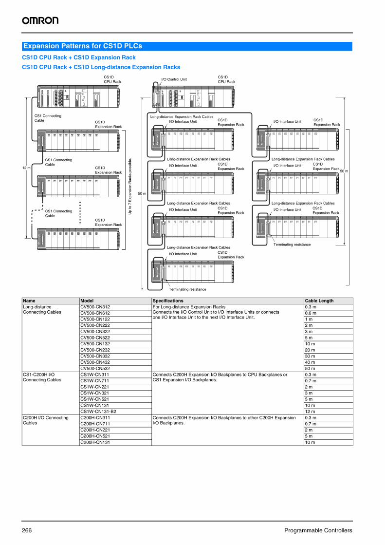
CS1D CPU Rack + CS1D Expansion Rack
CS1D CPU Rack + CS1D Long-distance Expansion Racks
Expansion Patterns for CS1D PLCs
Name Model Specifications Cable LengthLong-distance Connecting Cables
CV500-CN312 For Long-distance Expansion RacksConnects the I/O Control Unit to I/O Interface Units or connects one I/O Interface Unit to the next I/O Interface Unit.
0.3 mCV500-CN612 0.6 mCV500-CN122 1 mCV500-CN222 2 mCV500-CN322 3 mCV500-CN522 5 mCV500-CN132 10 mCV500-CN232 20 mCV500-CN332 30 mCV500-CN432 40 mCV500-CN532 50 m
CS1-C200H I/O Connecting Cables
CS1W-CN311 Connects C200H Expansion I/O Backplanes to CPU Backplanes or CS1 Expansion I/O Backplanes.
0.3 mCS1W-CN711 0.7 mCS1W-CN221 2 mCS1W-CN321 3 mCS1W-CN521 5 mCS1W-CN131 10 mCS1W-CN131-B2 12 m
C200H I/O Connecting Cables
C200H-CN311 Connects C200H Expansion I/O Backplanes to other C200H Expansion I/O Backplanes.
0.3 mC200H-CN711 0.7 mC200H-CN221 2 mC200H-CN521 5 mC200H-CN131 10 m
CSRDYTER ERR
IC102 CSRDYTER ERR
IC102
CSRDYTER ERR
IC102CSRDYTER ERR
IC102
CSRDYTER ERR
IC102 CSRDYTER ERR
IC102
CSRDYTER ERR
IC102
LEFT CPU
RIGHT CPU
DPL SW
ON
INIT.
ON
SW
DUPLEX
CSRDYTER ERR
IC102
50 m
50 m
LEFT CPU
RIGHT CPU
DPL SW
ON
INIT.
ON
SW
DUPLEXDUPLEX
12 m
CS1DCPU Rack
I/O Control Unit
I/O Interface Unit CS1DExpansion Rack
CS1DExpansion Rack
CS1DExpansion Rack
CS1DExpansion Rack
Long-distance Expansion Rack Cables
I/O Interface Unit
Long-distance Expansion Rack Cables
I/O Interface Unit
Long-distance Expansion Rack Cables
I/O Interface Unit
Long-distance Expansion Rack Cables
I/O Interface Unit CS1DExpansion Rack
CS1DExpansion Rack
CS1DExpansion Rack
I/O Interface Unit
Long-distance Expansion Rack Cables
I/O Interface Unit
Long-distance Expansion Rack Cables
Terminating resistance
Terminating resistance
CS1DCPU Rack
CS1DExpansion Rack
CS1DExpansion Rack
CS1DExpansion Rack
CS1 Connecting Cable
CS1 Connecting Cable
CS1 Connecting Cable
Up
to 7
Exp
ansi
on R
acks
pos
sibl
e.