2505 VIBRATION SENSOR INTERFACE MODULE INSTALLATION AND OPERATION … · 2019-04-09 · 2505...
62
2505 VIBRATION SENSOR INTERFACE MODULE INSTALLATION AND OPERATION GUIDE Version 1.2 CTI Part # 062-00353-012 062-00353-012 2505IOG 120105 $25
Transcript of 2505 VIBRATION SENSOR INTERFACE MODULE INSTALLATION AND OPERATION … · 2019-04-09 · 2505...

2505 VIBRATION SENSOR INTERFACE MODULE INSTALLATION AND OPERATION GUIDE
Version 1.2
CTI Part # 062-00353-012
*062-00353-012*
2505IOG 120105 $25
CTI 2505 Installation and Operation Guide ii
Copyright © 2005 Control Technology Inc.
All rights reserved. This manual is published by Control Technology Inc., 5734 Middlebrook Pike, Knoxville, TN 37921. This manual contains references to brand and product names which are tradenames, trademarks, and/or registered trademarks of Control Technology Inc. Siemens® and SIMATIC® are registered trademarks of Siemens AG. Other references to brand and product names are tradenames, trademarks, and/or registered trademarks of their respective holders. DOCUMENT DISCLAIMER STATEMENT Every effort has been made to ensure the accuracy of this document; however, errors do occasionally occur. CTI provides this document on an “as is” basis and assumes no responsibility for direct or consequential damages resulting from the use of this document. This document is provided without express or implied warranty of any kind, including but not limited to the warranties of merchantability or fitness for a particular purpose. This document and the products it references are subject to change without notice. If you have a comment or discover an error, please call us toll-free at 1-800-537-8398 or email us at [email protected].
REVISION HISTORY Version 1.0 12/5/03 Original Release Version 1.1 8/12/04 Incorporated SPQ393 (velocity probe leakage current) and SPQ396 (displacement probe used as tach source) into Board Rev D. Version 1.2 12/1/05
CTI 2505 Installation and Operation Guide iii
PREFACE
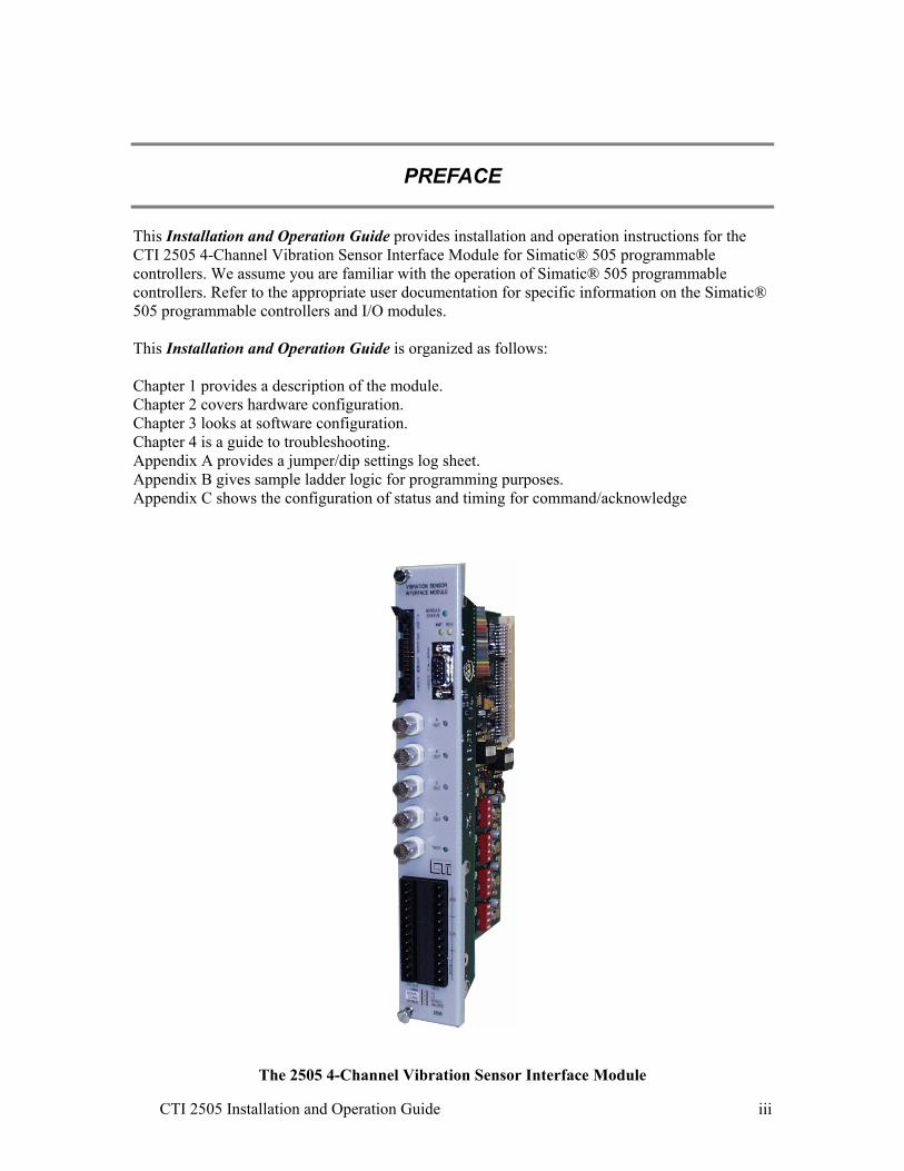
This Installation and Operation Guide provides installation and operation instructions for the CTI 2505 4-Channel Vibration Sensor Interface Module for Simatic® 505 programmable controllers. We assume you are familiar with the operation of Simatic® 505 programmable controllers. Refer to the appropriate user documentation for specific information on the Simatic® 505 programmable controllers and I/O modules. This Installation and Operation Guide is organized as follows: Chapter 1 provides a description of the module. Chapter 2 covers hardware configuration. Chapter 3 looks at software configuration. Chapter 4 is a guide to troubleshooting. Appendix A provides a jumper/dip settings log sheet. Appendix B gives sample ladder logic for programming purposes. Appendix C shows the configuration of status and timing for command/acknowledge
The 2505 4-Channel Vibration Sensor Interface Module

CTI 2505 Installation and Operation Guide iv
USAGE CONVENTIONS
NOTE: Notes alert the user to special features or procedures.
CAUTION: Cautions alert the user to procedures that could damage equipment.
WARNING: Warnings alert the user to procedures that could damage equipment and endanger the user.
CTI 2505 Installation and Operation Guide v
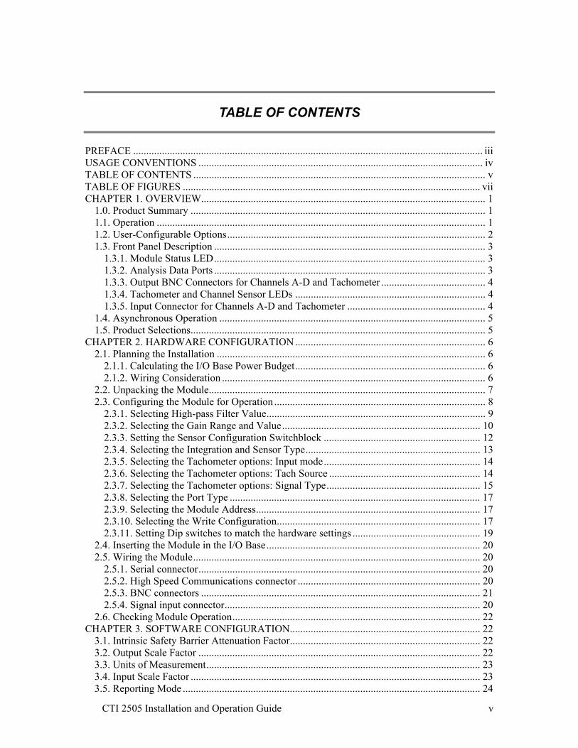
TABLE OF CONTENTS
PREFACE ...................................................................................................................................... iii USAGE CONVENTIONS ............................................................................................................. iv TABLE OF CONTENTS ................................................................................................................ v TABLE OF FIGURES .................................................................................................................. vii CHAPTER 1. OVERVIEW............................................................................................................. 1
1.0. Product Summary ................................................................................................................. 1 1.1. Operation .............................................................................................................................. 1 1.2. User-Configurable Options................................................................................................... 2 1.3. Front Panel Description ........................................................................................................ 3
1.3.1. Module Status LED........................................................................................................ 3 1.3.2. Analysis Data Ports ........................................................................................................ 3 1.3.3. Output BNC Connectors for Channels A-D and Tachometer ........................................ 4 1.3.4. Tachometer and Channel Sensor LEDs ......................................................................... 4 1.3.5. Input Connector for Channels A-D and Tachometer ..................................................... 4
1.4. Asynchronous Operation ...................................................................................................... 5 1.5. Product Selections................................................................................................................. 5
CHAPTER 2. HARDWARE CONFIGURATION......................................................................... 6 2.1. Planning the Installation ....................................................................................................... 6
2.1.1. Calculating the I/O Base Power Budget......................................................................... 6 2.1.2. Wiring Consideration ..................................................................................................... 6
2.2. Unpacking the Module.......................................................................................................... 7 2.3. Configuring the Module for Operation ................................................................................. 8
2.3.1. Selecting High-pass Filter Value.................................................................................... 9 2.3.2. Selecting the Gain Range and Value............................................................................ 10 2.3.3. Setting the Sensor Configuration Switchblock ............................................................ 12 2.3.4. Selecting the Integration and Sensor Type................................................................... 13 2.3.5. Selecting the Tachometer options: Input mode............................................................ 14 2.3.6. Selecting the Tachometer options: Tach Source .......................................................... 14 2.3.7. Selecting the Tachometer options: Signal Type........................................................... 15 2.3.8. Selecting the Port Type ................................................................................................ 17 2.3.9. Selecting the Module Address...................................................................................... 17 2.3.10. Selecting the Write Configuration.............................................................................. 17 2.3.11. Setting Dip switches to match the hardware settings ................................................. 19
2.4. Inserting the Module in the I/O Base.................................................................................. 20 2.5. Wiring the Module.............................................................................................................. 20
2.5.1. Serial connector............................................................................................................ 20 2.5.2. High Speed Communications connector ...................................................................... 20 2.5.3. BNC connectors ........................................................................................................... 21 2.5.4. Signal input connector.................................................................................................. 20
2.6. Checking Module Operation............................................................................................... 22 CHAPTER 3. SOFTWARE CONFIGURATION......................................................................... 22
3.1. Intrinsic Safety Barrier Attenuation Factor......................................................................... 22 3.2. Output Scale Factor ............................................................................................................ 22 3.3. Units of Measurement......................................................................................................... 23 3.4. Input Scale Factor ............................................................................................................... 23 3.5. Reporting Mode .................................................................................................................. 24
CTI 2505 Installation and Operation Guide vi
3.6. Trip Multiply Value ............................................................................................................ 24 3.7. Probe Sensitivity ................................................................................................................. 26 3.8. Alert / Danger Setpoints and Time Delays ......................................................................... 26 3.9. Displacement Probe Response Curve ................................................................................. 28 3.10. Gap Over/Under and Bias High/Low Alarm Setpoints .................................................... 29 3.11. Parameters that apply to All Channels.............................................................................. 29
CHAPTER 4. TROUBLESHOOTING ......................................................................................... 33 SPECIFICATIONS ....................................................................................................................... 35 APPENDIX A. JUMPER/DIP SETTINGS LOG SHEET ............................................................ 37 APPENDIX B. SAMPLE LADDER LOGIC................................................................................ 39 APPENDIX C. CONFIGURATION: STATUS AND TIMING FOR COMMAND/ACKNOWLEDGE.................................................................................................. 51 LIMITED PRODUCT WARRANTY........................................................................................... 54 REPAIR POLICY ......................................................................................................................... 55

CTI 2505 Installation and Operation Guide vii
TABLE OF FIGURES
Figure 1.1 CTI 2505 Front Panel...........................................................................................................3 Figure 1.1.a CTI 2505 Wiring Connector…………………………………………………………….4 Figure 1.2. Relation of Update Time Change in Signal Input ...............................................................5 Figure 2.1. Jumper and Switch locations...............................................................................................8 Figure 2.3. Selecting High-Pass Filter Value ........................................................................................9 Figure 2.4. Selecting the Gain Range and Value.................................................................................11 Figure 2.5. Selecting the Integration and Sensor Type........................................................................13 Figure 2.6. Bipolar gear tooth example ...............................................................................................15 Figure 2.7. Selecting Tachometer Options ..........................................................................................16 Figure 2.8. Selecting the Port Type, Module Address, and Write Configuration ...............................18 Figure 2.9. Jumper Settings for Future Reference...............................................................................19 Figure 2.10. I/O signal connectors ......................................................................................................20 Figure 2.11. I/O Configuration Chart .................................................................................................22 Figure 3.1. Alarm & Danger levels, Time Delay example chart .........................................................26 Figure 3.2. Displacement probe example chart ...................................................................................28 Figure 3.3. Time to Sample Correlation Chart ....................................................................................30 Figure 3.4. WX/WY Summary Chart..................................................................................................31 Figure 4.1 Troubleshooting Matrix ....................................................................................................33

CTI 2505 Installation and Operation Guide viii

CTI 2505 Installation and Operation Guide 1
CHAPTER 1. OVERVIEW
1.0. Product Summary The CTI 2505 Four Channel Vibration Sensor Interface Module is a member of Control Technology's family of I/O modules compatible with Simatic® 505 programmable controllers. The 2505 is designed to translate millivolt-level analog signals from velocity, accelerometer, and/or proximity sensors into digital words for a Simatic® 505 programmable controller (PLC). 1.1. Operation The 2505 Vibration Sensor Interface Module is a double-wide module. It logs in as 18WX and 22WY words. In operation the 2505 converts the signal coming from a vibration sensor into three pieces of information: the overall RMS vibration, the maximum reading (True Peak-to-Peak), and the DC bias of the probe circuit. There are four vibration input channels which are individually configurable for either an accelerometer, velocity sensor, or displacement probe. An additional input channel interfaces to a speed sensor; this can be either single or multiple-pulses per revolution. The first step in using the 2505 is to configure the hardware. Several jumpers and switches must be set for each channel to select the type of probe, the gain, the high-pass filter setting, and whether the hardware integration will be enabled. Jumpers must also be set to select the type of electrical interface for the tachometer circuitry. The next step is software configuration. The WY output words contain the parameters for each channel’s configuration. These are downloaded to the 2505 module one channel at a time using handshake bits to select the channel. Care should be taken to ensure the software parameters agree with the hardware settings; the module can check syntax on several of these. Parameters that can be specified include probe sensitivity, input and output scale factors, Alert and Danger setpoints and time delays, and the low-pass filter setting. All of these parameters are downloaded from the controller to the module via the WY output words. Once the 2505 hardware and software has been configured, the WX input words can be monitored for RMS, Peak-to-Peak, and DC bias on each vibration channel, and the speed from the tachometer (tach). Status bits offer quick identification of alarm levels (Alert, Danger, Probe Circuit status), tach status, Analog-Digital Converter (ADC) over-range conditions, and out-of-range for reported values. Note: Throughout this manual WX and WY are referenced as starting at a PLC log-in value of address 1; this is portrayed as WX(1) where the parentheses are used to indicate this is for reference only. These addresses must be changed to agree with the actual I/O addressing for each installation.

CTI 2505 Installation and Operation Guide 2
1.2. User-Configurable Options The following is a summary of user-configurable options: Probe type - accelerometer, velocity, or displacement Gain - interacts with maximum expected signal (full-scale reading) and probe sensitivity; sets resolution for channel Integration - accelerometer reports ips, or velocity reports mils Tachometer - single or multiple pulses per revolution, wide range of electrical pickups High-pass filter - seven steps between 1Hz to 100Hz Low-pass filter - sixteen steps between 1.5Hz to 50kHz; interacts with Number of Samples (lines of resolution) to determine how long it takes to sample the input channels I.S. barrier factor - compensates for attenuation introduced by external Intrinsic Safety barrier Units of measurement - either English or Metric Input and Output Scale factor - multipliers to achieve higher resolution Report mode - either mV or engineering units (g, ips, mils) Trip Multiply value - factor to multiply alarm levels Alert and Danger alarms - setpoints and time delays Bias alarms - upper and lower setpoints on the probe’s DC bias Displacement response curve - specification enables module to report displacement in mils or mV Port options - serial or parallel ports to access raw waveform data for analysis
CTI 2505 Installation and Operation Guide 3
1.3. Front Panel Description
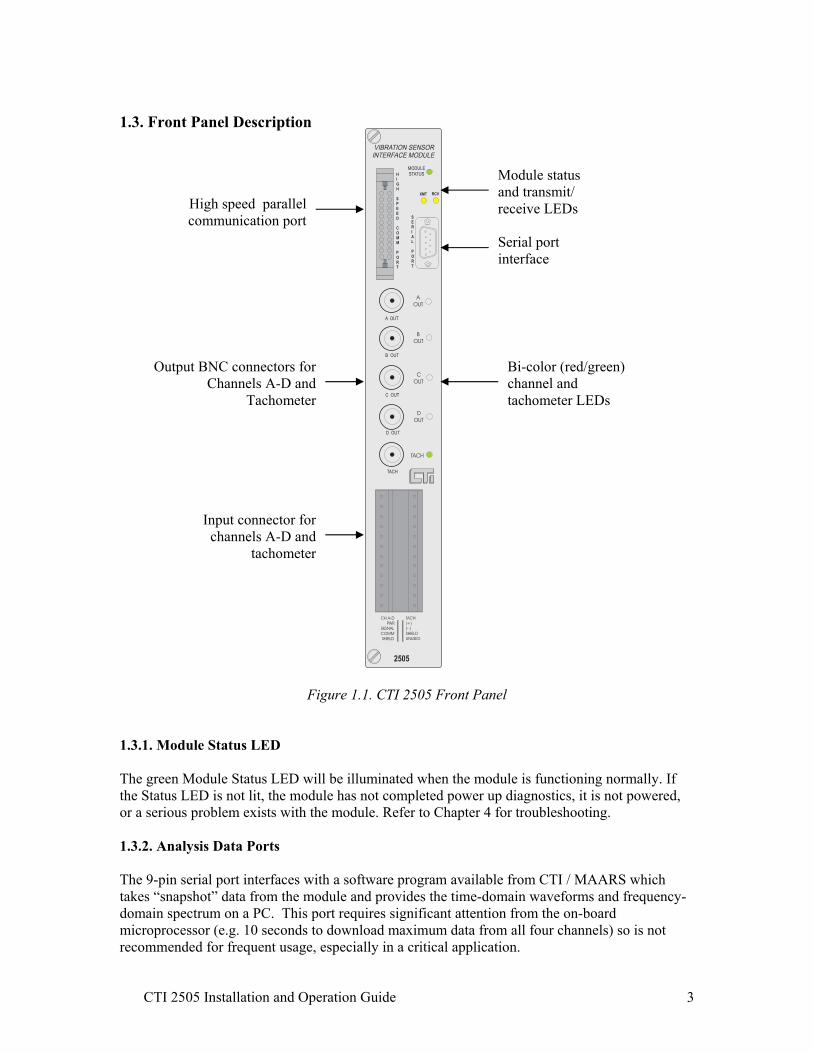
Figure 1.1. CTI 2505 Front Panel 1.3.1. Module Status LED The green Module Status LED will be illuminated when the module is functioning normally. If the Status LED is not lit, the module has not completed power up diagnostics, it is not powered, or a serious problem exists with the module. Refer to Chapter 4 for troubleshooting. 1.3.2. Analysis Data Ports The 9-pin serial port interfaces with a software program available from CTI / MAARS which takes “snapshot” data from the module and provides the time-domain waveforms and frequency-domain spectrum on a PC. This port requires significant attention from the on-board microprocessor (e.g. 10 seconds to download maximum data from all four channels) so is not recommended for frequent usage, especially in a critical application.
High speed parallel communication port
Output BNC connectors for Channels A-D and
Tachometer
Input connector for channels A-D and
tachometer
Module status and transmit/ receive LEDs
Serial port interface
Bi-color (red/green) channel and tachometer LEDs

CTI 2505 Installation and Operation Guide 4
The parallel port is provided for future use with a high-speed data interface. This port is much faster than the serial port and will not interfere with the normal scanning of the inputs. 1.3.3. Output BNC Connectors for Channels A-D and Tachometer Five individual BNC connectors for channels A-D and the tachometer signal are available for use with external analysis equipment. These are buffered but the signal output is not filtered.
1.3.4. Tachometer and Channel Sensor LEDs The bi-color (green and red) channel LEDs show the following operating modes: Solid green = channel configured and operating within limits Not lit = channel not configured or bad configuration Flashing green = Alert setpoint and time delay exceeded Flashing red = Danger setpoint and time delay exceeded Solid red = probe circuit fault (takes precedence over Alert or Danger indications) The single color (green) tachometer LED flashes in relation to speed of input signal. 1.3.5. Input Connector for Channels A-D and Tachometer This connector provides wiring terminals for channels A-D and for a tachometer signal. The wiring connector accepts 14-26 AWG wire.
Accelerometer Proximity probe
Velocity transducer
Figure 1.1.a. CTI 2505 Wiring Connector
PWR
SIGNAL
COMM
SHIELD
PWR
SIGNAL
COMM
SHIELD
PWR
SIGNAL
COMM
SHIELD
PWR
SIGNAL
COMM
SHIELD
( + )
( - )
SHIELD
NOT USED
NOT USED
NOT USED
NOT USED
NOT USED
CH A
CH B
CH C
CH D
TACH
CTI 2505 Installation and Operation Guide 5
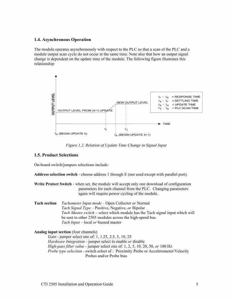
1.4. Asynchronous Operation The module operates asynchronously with respect to the PLC so that a scan of the PLC and a module output scan cycle do not occur at the same time. Note also that how an output signal change is dependent on the update time of the module. The following figure illustrates this relationship:
Figure 1.2. Relation of Update Time Change in Signal Input
1.5. Product Selections On-board switch/jumpers selections include: Address selection switch - choose address 1 through E (not used except with parallel port). Write Protect Switch - when set, the module will accept only one download of configuration
parameters for each channel from the PLC. Changing parameters again will require power cycling of the module.
Tach section Tachometer Input mode – Open Collector or Normal Tach Signal Type – Positive, Negative, or Bipolar
Tach Master switch – select which module has the Tach signal input which will be sent to other 2505 modules across the high-speed bus. Tach Input – local or bussed master
Analog input section (four channels)
Gain - jumper select one of: 1, 1.25, 2.5, 5, 10, 25 Hardware Integration - jumper select to enable or disable High-pass filter value - jumper select one of: 1, 2, 5, 10, 20, 50, or 100 Hz Probe type selection - switch select of : Proximity Probe or Accelerometer/Velocity
Probes and/or Probe bias

CTI 2505 Installation and Operation Guide 6
CHAPTER 2. HARDWARE CONFIGURATION
The installation of the Vibration Sensor Interface Module involves the following steps: 1. Planning the installation 2. Unpacking the module 3. Configuring the module 4. Wiring the module 5. Checking module operation The steps listed above are explained in detail in the following pages. 2.1. Planning the Installation Planning is the first step in the installation of the module. This involves calculating the I/O base power budget and routing the input signal wiring to minimize noise. The following sections discuss these important considerations. 2.1.1. Calculating the I/O Base Power Budget The 2505 requires 14 watts of +5 VDC power from the I/O base. Before inserting the module into the I/O base, ensure that the I/O base power supply capacity is not exceeded. The power supply should be a single voltage, 20-28 VDC nominal 2.0 amp, UL Class 2 device. The drive voltage and current are specified at 24 VDC. 2.1.2. Wiring Consideration Power, communication, and signal wiring must be separated to prevent noise in the signal wiring. Input signal wiring must be shielded, twisted-pair cable, with 14 to 26 gauge stranded conductors. The cable shield should always be terminated to earth ground at the I/O base. It should not be terminated at the output connector. Use the following guidelines when wiring the module: • Always use the shortest possible cables • Avoid placing power supply wires and signal wires near sources of high energy • Avoid placing low voltage wire parallel to high energy wire (if the two wires must meet,
cross them at a right angle) • Avoid bending the wires into sharp angles • Use wireways for wire routing • Be sure to provide a proper earth ground for the cable shield at the I/O base • Avoid placing wires on any vibrating surfaces

CTI 2505 Installation and Operation Guide 7
2.2. Unpacking the Module Open the shipping carton and remove the special anti-static bag which contains the module.
CAUTION: HANDLING STATIC SENSITIVE DEVICES
The components on the 2505 module printed circuit card can be damaged by static electricity discharge. To prevent this damage, the module is shipped in a special anti-static
bag. Static control precautions should be followed when removing the module from the bag, when opening the module, and when handling the printed circuit card during
configuration. After discharging any static build-up, remove the module from the static bag. Do not discard the static bag. Always use this bag for protection against static damage when the module is not inserted into the I/O backplane.
WARNING: Ensure that the power supply is turned OFF before connecting the wires to the I/O base.
CTI 2505 Installation and Operation Guide 8
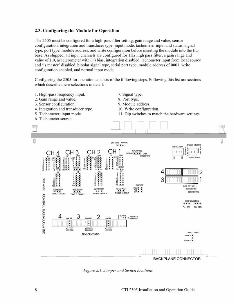
2.3. Configuring the Module for Operation The 2505 must be configured for a high-pass filter setting, gain range and value, sensor configuration, integration and transducer type, input mode, tachometer input and status, signal type, port type, module address, and write configuration before inserting the module into the I/O base. As shipped, all input channels are configured for 1Hz high pass filter, a gain range and value of 1.0, accelerometer with (+) bias, integration disabled, tachometer input from local source and ‘is master’ disabled, bipolar signal type, serial port type, module address of 0001, write configuration enabled, and normal input mode. Configuring the 2505 for operation consists of the following steps. Following this list are sections which describe these selections in detail. 1. High-pass frequency input. 7. Signal type. 2. Gain range and value. 8. Port type. 3. Sensor configuration. 9. Module address. 4. Integration and transducer type. 10. Write configuration. 5. Tachometer: input mode. 11. Dip switches to match the hardware settings. 6. Tachometer source.
Figure 2.1. Jumper and Switch locations

CTI 2505 Installation and Operation Guide 9
2.3.1. Selecting High-pass Filter Value The 2505 allows high-pass filter values to be set for each of the four channels. This value must match the WY configuration in the PLC. For each channel, the high-pass filter must be set in three places: two hardware jumpers and a switch bank. The jumpers are on the field side of the circuitry and the switch bank is on the digital logic side of the isolation barrier. As shipped, the 1 Hz filter value is selected. Refer to the diagram below for the correct settings for a 5Hz example.
Figure 2.3. Selecting High-Pass Filter Value
WY(20)
nibble 1 nibble 2 nibble 3 nibble 4
Transducer Type & Integration
Gain
High-pass Filter
Not Defined 0, 1, 2, 3, 4, 5, 6

CTI 2505 Installation and Operation Guide 10
2.3.2. Selecting the Gain Range and Value The Gain settings of ‘Range’ and ‘Value’ must be set in three places for each channel of the module: two jumpers and a switch bank. The corresponding value must also be entered in the WY(20) nibble 2 configuration word. Use the table below to correlate these two values and choose a gain setting for the channel. When the module is operating, status bits WX(15.13) through WX(15.16) can be monitored to check for an Analog-Digital Converter (ADC) over-range condition. If the bit is ON, that indicates the gain setting is set too high for that channel, i.e. the ADC is getting too much voltage from the vibration sensor. A graphical picture would show the input signal clipping. Move the gain to a lower setting if this occurs.
Probe Sensitivity (specified by manufacturer) ADC max
WY(20) nibble 2
Resolution in mV
Gain 50mV 100mV 200mV 500mV
5V 0 2.441 1 100 50 25 10 4V 1 1.953 1.25 80 40 20 8 2V 2 0.976 2.5 40 20 10 4 1V 3 0.488 5 20 10 5 2
500mV 4 0.244 10 10 5 2.5 1 200mV 5 .0976 25 4 2 1 0.4
Full Scale Range

CTI 2505 Installation and Operation Guide 11
Figure 2.4. Selecting the Gain Range and Value
WY(20)
nibble 1 nibble 2 nibble 3 nibble 4
Transducer Type & Integration
High-pass Filter
Gain
Not Defined 0, 1, 2, 3, 4, 5
CTI 2505 Installation and Operation Guide 12
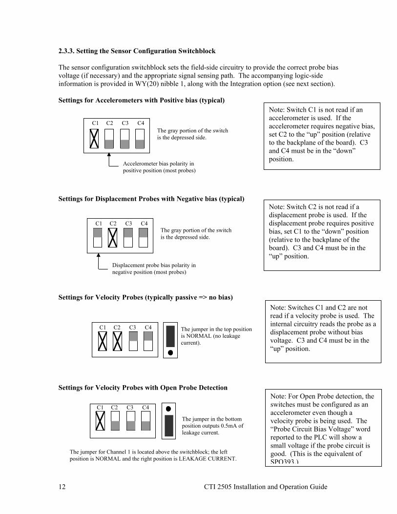
2.3.3. Setting the Sensor Configuration Switchblock The sensor configuration switchblock sets the field-side circuitry to provide the correct probe bias voltage (if necessary) and the appropriate signal sensing path. The accompanying logic-side information is provided in WY(20) nibble 1, along with the Integration option (see next section). Settings for Accelerometers with Positive bias (typical) Settings for Displacement Probes with Negative bias (typical) Settings for Velocity Probes (typically passive => no bias) Settings for Velocity Probes with Open Probe Detection
Accelerometer bias polarity in positive position (most probes)
The gray portion of the switch is the depressed side.
C1 C2 C3 C4
Note: Switch C1 is not read if an accelerometer is used. If the accelerometer requires negative bias, set C2 to the “up” position (relative to the backplane of the board). C3 and C4 must be in the “down” position.
Note: Switch C2 is not read if a displacement probe is used. If the displacement probe requires positive bias, set C1 to the “down” position (relative to the backplane of the board). C3 and C4 must be in the “up” position.
C1 C2 C3 C4
Note: Switches C1 and C2 are not read if a velocity probe is used. The internal circuitry reads the probe as a displacement probe without bias voltage. C3 and C4 must be in the “up” position.
Displacement probe bias polarity in negative position (most probes)
The gray portion of the switch is the depressed side.
C1 C2 C3 C4
The jumper in the top position is NORMAL (no leakage current).
C1 C2 C3 C4
Note: For Open Probe detection, the switches must be configured as an accelerometer even though a velocity probe is being used. The “Probe Circuit Bias Voltage” word reported to the PLC will show a small voltage if the probe circuit is good. (This is the equivalent of SPQ393.)
The jumper in the bottom position outputs 0.5mA of leakage current.
C1 C2 C3 C4
The jumper for Channel 1 is located above the switchblock; the left position is NORMAL and the right position is LEAKAGE CURRENT.
CTI 2505 Installation and Operation Guide 13
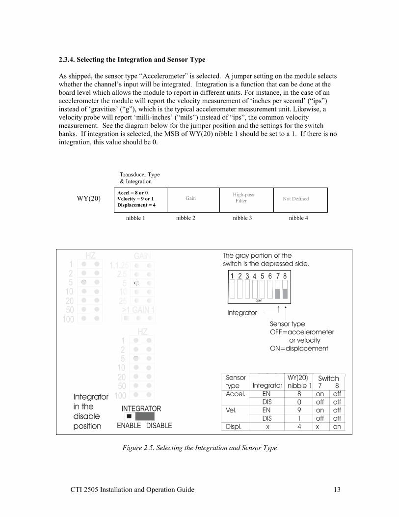
2.3.4. Selecting the Integration and Sensor Type As shipped, the sensor type “Accelerometer” is selected. A jumper setting on the module selects whether the channel’s input will be integrated. Integration is a function that can be done at the board level which allows the module to report in different units. For instance, in the case of an accelerometer the module will report the velocity measurement of ‘inches per second’ (“ips”) instead of ‘gravities’ (“g”), which is the typical accelerometer measurement unit. Likewise, a velocity probe will report ‘milli-inches’ (“mils”) instead of “ips”, the common velocity measurement. See the diagram below for the jumper position and the settings for the switch banks. If integration is selected, the MSB of WY(20) nibble 1 should be set to a 1. If there is no integration, this value should be 0.
Figure 2.5. Selecting the Integration and Sensor Type
WY(20)
nibble 1 nibble 2 nibble 3 nibble 4
Transducer Type & Integration
Gain
High-pass Filter Not Defined
Accel = 8 or 0 Velocity = 9 or 1 Displacement = 4
CTI 2505 Installation and Operation Guide 14
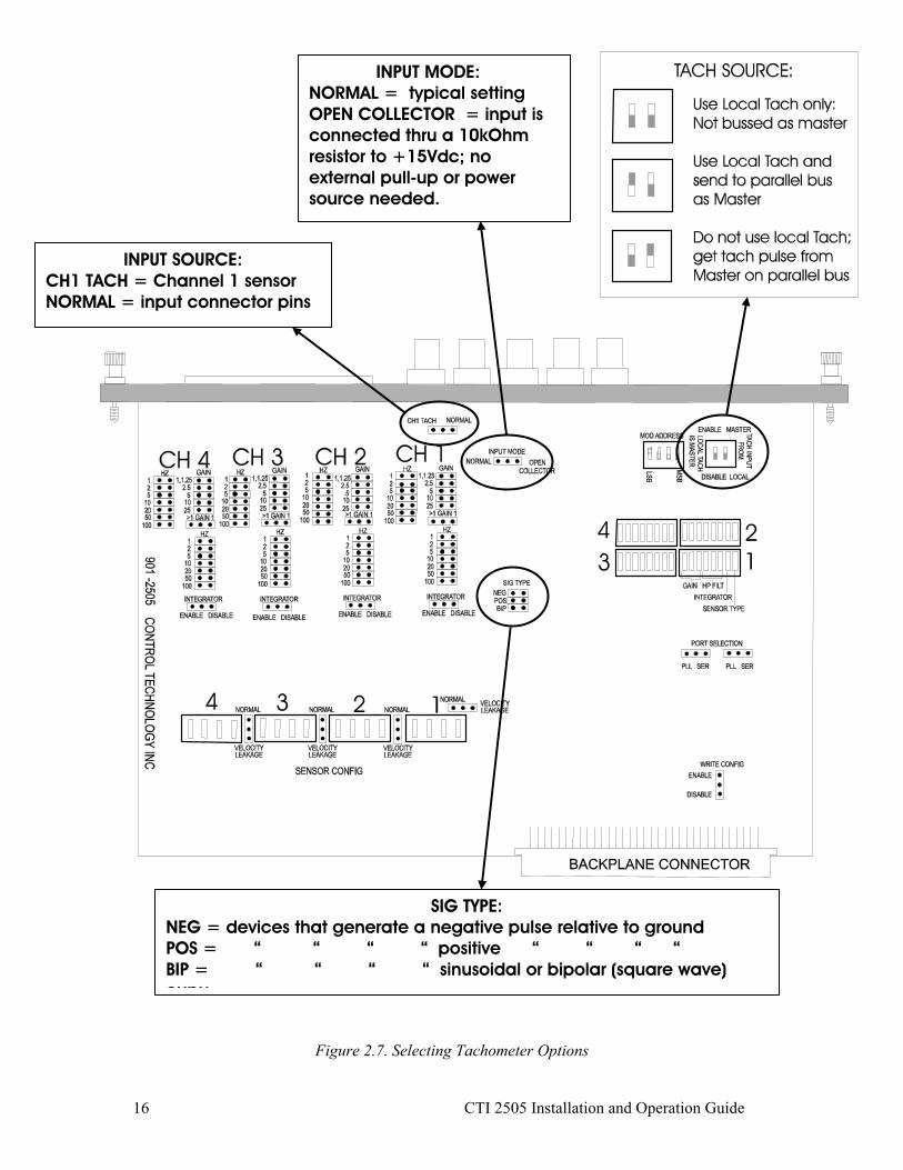
2.3.5. Selecting the Tachometer options: Input mode The input signal for the 2505 tachometer circuit can come from either the input connector or from Channel 1 (Channel A on the input connector). If the tach source is from a mag pickup or other such device, the input connector should be wired directly to the device. Alternatively, the input source could be a displacement transducer which is sensing a keyslot or a drilled hole in a shaft. In this case the source will come from the Channel 1 input circuit. The advantage of using a displacement transducer is that it can be monitored for probe circuit status since it is a powered probe. A mag pickup is a passive device therefore the difference between an open circuit or a non-moving object cannot be detected; both report a 0 input. Jumper JP95 selects whether the tach circuit will receive its signal from Channel 1 or from the input connector. If Channel 1 is selected, the input voltage threshhold is raised by an order of magnitude to remove the “noise” of the vibration signal. The actual tach pulse is a comparatively high voltage level so the gain for Channel 1 should be set to its lowest value of 1. The Channel 1 input circuit removes the DC bias from the sensor’s input signal before sending it over to the tach circuit. (Note: This was first implemented as SPQ396 which used Channel 4 for the input.) The connector input can be a single pulse per revolution, multiple pulses per revolution such as blades on a fan or teeth on a gear, or a TTL pulse train (either + or -). The tach circuitry can sense voltages from 140mV to 50V from normal or open collector circuits, with a frequency resolution of 1Hz (maximum 65kHz). If the tach is a single pulse per revolution, this signal can be used as a synchronization mark in analyzing the vibration waveforms since all channels on a single 2505 are obtained synchronously. In addition, the tach signal can be bussed across the high speed parallel port interface between multiple 2505 modules to provide a common reference. The type of tach input (normal or open collector) is set by jumper JP17. Normal is the default setting. Open Collector input is connected internally through a 10kΩ resistor to +15Vdc; no external pull-up resistor or power supply is needed. The status of the tachometer circuitry is available in WX(15). Bit 2 indicates a tach overrange condition; this means the pulses are exceeding 65535 counts. This could occur if a toothed gear is used at a high speed. Bit 3 is the tach underrange status bit; this means the speed is less than 2Hz. After 10 seconds without pulses, the No Tach (bit 4) will be set. 2.3.6. Selecting the Tachometer options: Tach Source If multiple 2505 modules are connected using the high speed parallel port interface, the tach signal can be sourced from any 2505 and bussed to the other modules. The selection of whether the tach is used locally only or as the master tach is made using switch block SW5. The options are: Local tach only – tach source is connected to this 2505 and is not bussed to other modules Local tach is Master – tach source is connected to this 2505 and is bussed to other modules Use Master tach – tach source is on another 2505 and is bussed to this module

CTI 2505 Installation and Operation Guide 15
2.3.7. Selecting the Tachometer options: Signal Type Signal type (positive, negative, or bipolar) is set by jumpers J1, J2, or J3. A negative signal type is used when devices generate a negative pulse relative to ground, a positive setting is for devices that generate a positive pulse relative to ground, and bipolar is used for devices that generate a sinusoidal or bipolar (square wave) output. A gear tooth or blade pass waveform uses the bipolar setting. See figure below for correct signal polarity.
Figure 2.6. Bipolar gear tooth example
Configuration word WY(40) determines whether the tach pulses coming from the hardware circuitry are counted as once per revolution or as multiple pulses per revolution. If WY(40) is set to 0, the speed as sensed from the tach is reported to the PLC WX(14) in Hertz; an RPM selection is not possible. If WY(40) is set to 1, that equates to a single pulse per revolution. The choice of speed reporting is made by setting WY(19.6) to 1 for Hertz or 0 for RPM. For teeth on a gear or blade passes, set WY(40) equal to the number of teeth on the gear (or vanes on the fan).
Magnetic pickup
Teeth on gear
Output waveform
approaching departing
parallel to pickup
CTI 2505 Installation and Operation Guide 16
Figure 2.7. Selecting Tachometer Options
INPUT MODE: NORMAL = typical setting OPEN COLLECTOR = input is connected thru a 10kOhm resistor to +15Vdc; no external pull-up or power source needed.
SIG TYPE: NEG = devices that generate a negative pulse relative to ground POS = “ “ “ “ positive “ “ “ “ BIP = “ “ “ “ sinusoidal or bipolar (square wave) oupu
INPUT SOURCE: CH1 TACH = Channel 1 sensor NORMAL = input connector pins

CTI 2505 Installation and Operation Guide 17
2.3.8. Selecting the Port Type The port type can either be parallel or serial and is selected on jumpers JP88 and JP89 (see Figure 2.8. on next page). If the 2505 is not paired with a 2506 Vibration Sensor Analysis Module (available mid-2004), then the serial port should be selected. This enables the DB9 serial port on the front of the module. A software package is available from CTI / MAARS which is capable of downloading waveform data from the serial port in a “snapshot” mode. This data can be portrayed as a time domain waveform or as a frequency domain spectrum. The historical trending and analysis features of the 2506 Vibration Sensor Analysis Module are not available in this mode. The 2505 stops processing vibration input data during this download process so it is recommended that this capability not be used frequently if the module is monitoring critical machinery for shutdown purposes. The purpose of the parallel port interface is to connect the 2505(s) to the 2506 Vibration Sensor Analysis Module. This bus transfers waveform data at a speed which does not interfere with the ability of the 2505 to continuously monitor the vibration signals. The status of the port activity is available in WX(15). Bit 11 indicates if the processor on the 2505 has been halted due to activity on either the serial or parallel port. Bit 12 indicates a timeout condition due to a failure of the 2506 to respond to a signal from the 2505. 2.3.9. Selecting the Module Address The module address is set via switchblock SW10 (see Figure 2.8. on next page). It is only used when the 2506 Vibration Sensor Analysis Module (available mid-2004) is in the system. Two addresses are reserved: address 0 is always the 2506, and an address of F (hex) is used for the 2506 to broadcast to all 2505s. The 2505 can therefore be address 1 through E (hex) and is shipped with the 0001 address. 2.3.10. Selecting the Write Configuration The Write Configuration is set via jumper JP20 (see Figure 2.8. on next page). In the Enable position, the 2505 can be dynamically configured from the PLC at any time. In this mode, changes can be made to one channel’s parameters, e.g. Alarm Delay Time, without affecting the operation of any other channel. If the application is sensitive or perhaps subject to agency regulation, the jumper can be set to Disable. In this mode, only one set of configuration parameters can be downloaded to each channel. Dynamic changes are not accepted by the 2505. To effect a change, the module must be power cycled, then another set of parameters will be accepted.

CTI 2505 Installation and Operation Guide 18
Figure 2.8. Selecting the Port Type, Module Address, and Write Configuration

CTI 2505 Installation and Operation Guide 19
2.3.11. Setting Dip switches to match the hardware settings Once the hardware jumpers are selected this information needs to be reported to the microcomputer. The information is reported via DIP switches SW6, 7, 11, and 12. Each channel uses 8 rocker switches with a BCD code to indicate the state of the hardware jumpers. The 2505 compares the state of these switches to the configuration word WY(20) which comes from the user’s program in the PLC. Because of the need to isolate the field-side circuitry from the logic-side, there is no physical check to make sure the module is configured the same as the PLC “thinks” it is. These switches are simply a step to help ensure there are no setup mis-matches.
Channel Dip Position(s)
BCD code Corresponding Value
1-3 000 Gain = 1.0 1-3 100 Gain = 1.25 1-3 010 Gain = 2.50 1-3 110 Gain = 5 1-3 001 Gain = 10 1-3 101 Gain = 25 1-3 110 N/A 1-3 111 N/A 4-6 000 High Pass Filter = 1Hz 4-6 100 High Pass Filter = 2 Hz 4-6 010 High Pass Filter = 5 Hz 4-6 110 High Pass Filter = 10 Hz 4-6 001 High Pass Filter = 20 Hz 4-6 101 High Pass Filter = 50 Hz 4-6 011 High Pass Filter = 100 Hz 4-6 111 N/A 7 0 Integrator Value = Disabled 7 1 Integrator Value = Enabled 8 0 Sensor type =
Accelerometer or Velocity Probe
8 1 Sensor type = Displacement Probe
Figure 2.9. Jumper Settings for Future Reference
See “Appendix A. Jumper Settings Log Sheet” to document individual channel settings after making copies for each of the four channels.
CTI 2505 Installation and Operation Guide 20
2.4. Inserting the Module in the I/O Base Insert the module into the I/O base by carefully pushing the module into the slot. When the module is fully seated in the slot and backplane connector, tighten the captive screws at the top and bottom to hold the module in place. To remove the module from the I/O base loosen the captive screws then remove the module from the I/O base. 2.5. Wiring the Module Input and output signals travel through a variety of connectors accessible on the front panel of the module: a 9-pin serial connector, a high speed 24-pin communications connector with latches, a group of five BNC connectors, and a dual row 24-pin connector. Each connector type and its function is described below. 2.5.1. Serial connector The 9-pin D-SUB serial connector interfaces with a software program available from CTI/MAARS which takes “snapshot “ data from the module and provides the time-domain waveforms and frequency-domain spectrum on a PC. This port requires significant attention from the on-board microprocessor (e.g. 10 seconds to download maximum data from all four channels) so is not recommended for frequent usage, especially in a critical application. 2.5.2. High Speed Communications connector The 24-pin connector acts as a high speed communication connector to transfer signals between the 2505 and a vibration data analysis program. This port is much faster than the serial port and will not interfere with the normal scanning of the inputs. 2.5.3. BNC connectors Five individual BNC connectors for channels A-D and the tachometer signal are available for use with external analysis equipment. These are buffered but the signal output is not filtered. 2.5.4. Signal input connector This connector provides wiring terminals for channels A-D and for a tachometer signal. The wiring connector accepts 14-26 AWG solid or stranded wire.
CTI 2505 Installation and Operation Guide 21
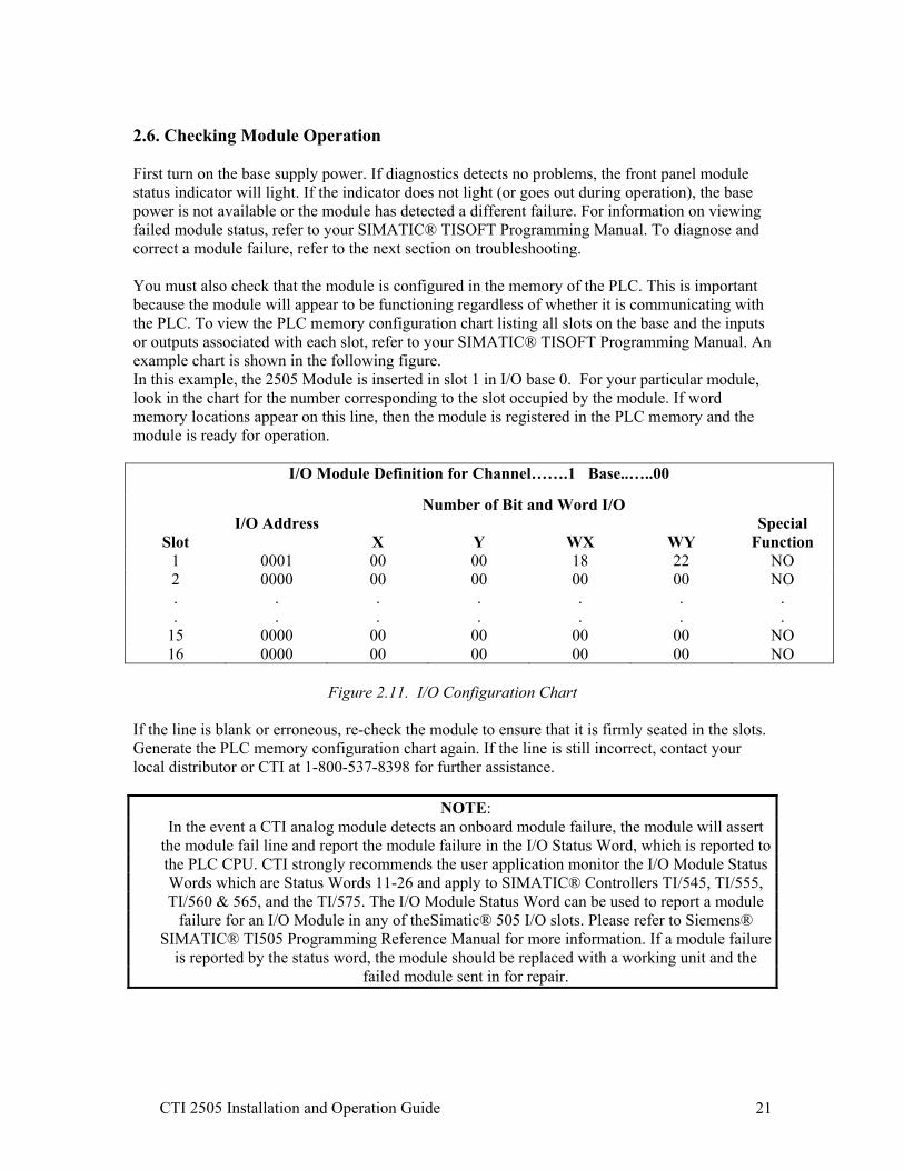
2.6. Checking Module Operation First turn on the base supply power. If diagnostics detects no problems, the front panel module status indicator will light. If the indicator does not light (or goes out during operation), the base power is not available or the module has detected a different failure. For information on viewing failed module status, refer to your SIMATIC® TISOFT Programming Manual. To diagnose and correct a module failure, refer to the next section on troubleshooting. You must also check that the module is configured in the memory of the PLC. This is important because the module will appear to be functioning regardless of whether it is communicating with the PLC. To view the PLC memory configuration chart listing all slots on the base and the inputs or outputs associated with each slot, refer to your SIMATIC® TISOFT Programming Manual. An example chart is shown in the following figure. In this example, the 2505 Module is inserted in slot 1 in I/O base 0. For your particular module, look in the chart for the number corresponding to the slot occupied by the module. If word memory locations appear on this line, then the module is registered in the PLC memory and the module is ready for operation.
I/O Module Definition for Channel…….1 Base..…..00
Number of Bit and Word I/O
Slot I/O Address
X
Y
WX
WY Special
Function 1 0001 00 00 18 22 NO 2 0000 00 00 00 00 NO . .
.
. . .
.
. . .
.
. . .
15 0000 00 00 00 00 NO 16 0000 00 00 00 00 NO
Figure 2.11. I/O Configuration Chart
If the line is blank or erroneous, re-check the module to ensure that it is firmly seated in the slots. Generate the PLC memory configuration chart again. If the line is still incorrect, contact your local distributor or CTI at 1-800-537-8398 for further assistance.
NOTE: In the event a CTI analog module detects an onboard module failure, the module will assert
the module fail line and report the module failure in the I/O Status Word, which is reported to the PLC CPU. CTI strongly recommends the user application monitor the I/O Module Status Words which are Status Words 11-26 and apply to SIMATIC® Controllers TI/545, TI/555, TI/560 & 565, and the TI/575. The I/O Module Status Word can be used to report a module
failure for an I/O Module in any of theSimatic® 505 I/O slots. Please refer to Siemens® SIMATIC® TI505 Programming Reference Manual for more information. If a module failure
is reported by the status word, the module should be replaced with a working unit and the failed module sent in for repair.
CTI 2505 Installation and Operation Guide 22
CHAPTER 3. SOFTWARE CONFIGURATION
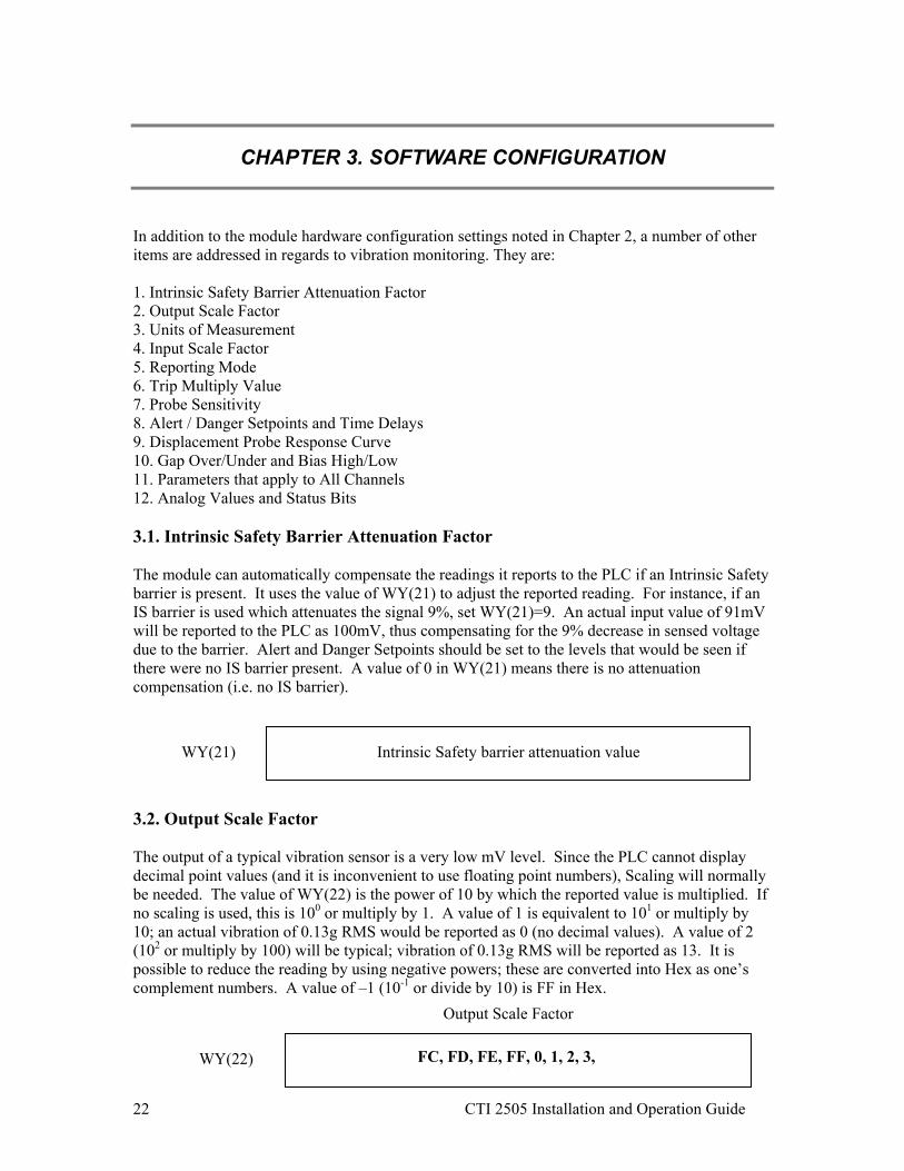
In addition to the module hardware configuration settings noted in Chapter 2, a number of other items are addressed in regards to vibration monitoring. They are: 1. Intrinsic Safety Barrier Attenuation Factor 2. Output Scale Factor 3. Units of Measurement 4. Input Scale Factor 5. Reporting Mode 6. Trip Multiply Value 7. Probe Sensitivity 8. Alert / Danger Setpoints and Time Delays 9. Displacement Probe Response Curve 10. Gap Over/Under and Bias High/Low 11. Parameters that apply to All Channels 12. Analog Values and Status Bits 3.1. Intrinsic Safety Barrier Attenuation Factor The module can automatically compensate the readings it reports to the PLC if an Intrinsic Safety barrier is present. It uses the value of WY(21) to adjust the reported reading. For instance, if an IS barrier is used which attenuates the signal 9%, set WY(21)=9. An actual input value of 91mV will be reported to the PLC as 100mV, thus compensating for the 9% decrease in sensed voltage due to the barrier. Alert and Danger Setpoints should be set to the levels that would be seen if there were no IS barrier present. A value of 0 in WY(21) means there is no attenuation compensation (i.e. no IS barrier). 3.2. Output Scale Factor The output of a typical vibration sensor is a very low mV level. Since the PLC cannot display decimal point values (and it is inconvenient to use floating point numbers), Scaling will normally be needed. The value of WY(22) is the power of 10 by which the reported value is multiplied. If no scaling is used, this is 100 or multiply by 1. A value of 1 is equivalent to 101 or multiply by 10; an actual vibration of 0.13g RMS would be reported as 0 (no decimal values). A value of 2 (102 or multiply by 100) will be typical; vibration of 0.13g RMS will be reported as 13. It is possible to reduce the reading by using negative powers; these are converted into Hex as one’s complement numbers. A value of –1 (10-1 or divide by 10) is FF in Hex.
WY(21) Intrinsic Safety barrier attenuation value
WY(22)
Output Scale Factor
FC, FD, FE, FF, 0, 1, 2, 3, 4
CTI 2505 Installation and Operation Guide 23
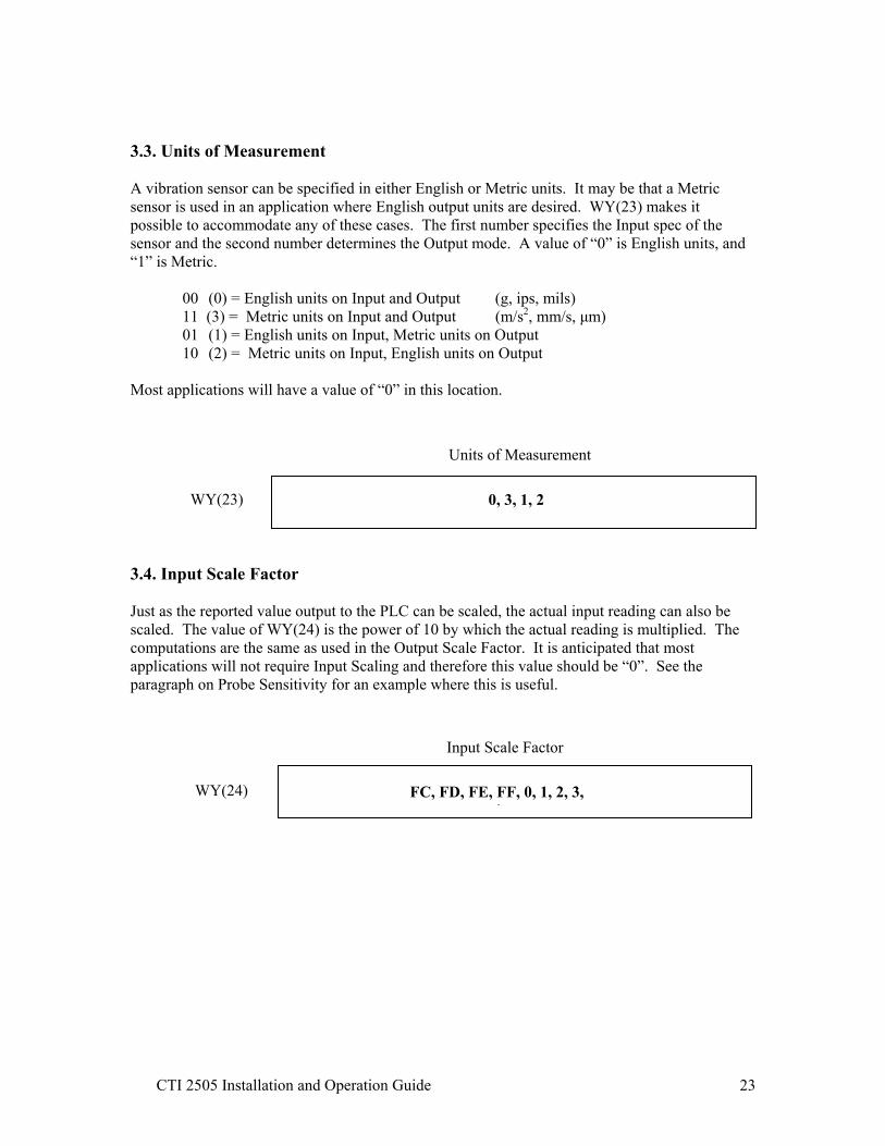
3.3. Units of Measurement A vibration sensor can be specified in either English or Metric units. It may be that a Metric sensor is used in an application where English output units are desired. WY(23) makes it possible to accommodate any of these cases. The first number specifies the Input spec of the sensor and the second number determines the Output mode. A value of “0” is English units, and “1” is Metric.
00 (0) = English units on Input and Output (g, ips, mils) 11 (3) = Metric units on Input and Output (m/s2, mm/s, µm) 01 (1) = English units on Input, Metric units on Output 10 (2) = Metric units on Input, English units on Output
Most applications will have a value of “0” in this location. 3.4. Input Scale Factor Just as the reported value output to the PLC can be scaled, the actual input reading can also be scaled. The value of WY(24) is the power of 10 by which the actual reading is multiplied. The computations are the same as used in the Output Scale Factor. It is anticipated that most applications will not require Input Scaling and therefore this value should be “0”. See the paragraph on Probe Sensitivity for an example where this is useful.
WY(23)
Units of Measurement
0, 3, 1, 2
WY(24)
Input Scale Factor
FC, FD, FE, FF, 0, 1, 2, 3, 4

CTI 2505 Installation and Operation Guide 24
3.5. Reporting Mode The module receives a mV signal input from the vibration sensor and translates this into the equivalent vibration reading based on the sensor specifications and other variables. In some cases it may be desired to know the actual voltage reading instead of the vibration value. WY(25) chooses whether the reported value is in Engineering Units or the raw mV. There is also a choice of type of output: RMS is normally used and is an “average” of the input readings.
Peak is a computed value equal to the RMS value times 1.4. Peak-Peak is a computed value equal to the Peak value times 2. Do not confuse this with the True Peak-to-Peak value which the module also reports.
0 = RMS raw mV 1 = RMS engineering units 2 = peak raw mV 3 = peak engineering units 4 = p-p raw mV 5 = p-p engineering units It is possible to select a mode that exceeds the range of a signed integer data type (-32765 to 32767), yet have an actual vibration level that is OK. For example: Output Scale of 100 reporting in RMS engineering units gives an acceptable reading. Changing the Scale factor or the Report Mode may cause the reported value to exceed +32767. Always check the WX(15.10) Math Overflow status bit to ensure the reported value is legitimate. 3.6. Trip Multiply Value If the module is calculating the Alarm and Danger Setpoints, then it can go into Trip Multiply mode where the setpoints are raised by the factor specified in WY(26). This Trip Multiply Value can be set on a per-channel basis and is activated when the module receives the WY(19.8) command bit from the PLC. Trip Multiply mode is maintained until the command bit is lowered. For instance, an alarm setpoint of 2 g’s can be raised to 3 g’s during startup or coastdown to avoid harmonic regions and spurious alarms. The value of WY(26) would be set to “1” indicating a 50% increase in setpoint. The possible values for WY(26) are: 0 = no change in Setpoint 1 = 50% increase in Setpoint 2 = 100% increase 4 = 150% increase 8 = 200% increase
WY(25)
Reporting Mode
0, 1, 2, 3, 4, 5
WY(26) Trip Multiply Value

CTI 2505 Installation and Operation Guide 25
3.7. Probe Sensitivity The sensitivity of a vibration probe is specified by the manufacturer and is typically a nominal value such as 100mV/g (accelerometer) or 200mV/mil (displacement probe). The 2505 expects this parameter to be expressed in terms of RMS. This is normal for accelerometers however velocity transducers are often specified as 145mV/ips peak. This value needs to be converted to RMS (by dividing by 1.414) which yields 102.6mv/ips RMS. This can in most instances be approximated as a sensitivity of 100. The module can go a step further and accept the more accurate calibrated value if it is known. It can also accept Metric inputs with decimal values; the WY(24) Input Scale Factor is used. For example: 200mV/mil prox probe WY(27) = 200 WY(24) = 0 7.87mV/µm prox probe WY(27) = 787 WY(24) = FE (10-2) 10.2mV/m/s2 accelerometer WY(27) = 102 WY(24) = FF (10-1) 102mV/g calibrated accel WY(27) = 102 WY(24) = 0 3.8. Alert / Danger Setpoints and Time Delays The next four configuration words (WY(28) through WY(31)) specify the Alarm and Danger levels, and Time Delays. If the module is not calculating alarms (control bit WY(19.5) is ON) then no values need to be entered. Note: If setpoints are not entered and Alarm Control = 1, then the front panel LEDs will always remain at solid green. For applications where alarm calculations are desired, refer to the following figure for assistance in determining appropriate values.
Figure 3.1. Alarm & Danger levels, Time Delay example chart
WY(27) Probe Sensitivity
Time
Vol
tage
Nominal DC bias voltage
Gap Over or Bias High
Gap Under or Bias Low
Danger Setpoint
Alert Setpoint
True Peak-to-Peak

CTI 2505 Installation and Operation Guide 26
The 2505 allows several options in how vibration levels are alarmed. The first choice is whether to alarm on a level that is calculated or on the True Peak-to-Peak. As a vibration signal comes into the 2505, it is transformed by the analog-to-digital (ADC) converter into a digital representation. A math process converts the raw data points into an RMS (Root Mean Square) value. This is often called the Overall Vibration value and is very roughly analogous to the average of all the data values. Since the math process is an averaging function, the effect of a single peak on the overall value is reduced. From this RMS value, two other representations are possible: the calculated Peak (1.4 x RMS) and the calculated Peak-to-Peak (1.4 x RMS x 2). It is important to distinguish that these are calculated values. If the vibration waveform is a true sine wave, then the calculated values would correlate exactly with the actual peak and peak-to-peak measurements. Since vibration is never a perfect sine wave, these are therefore approximations based on calculated values. The 2505 does give the option of alarming on the True Peak-to-Peak. This is demonstrated graphically in Figure 3.1, and is obtained by adding the maximum positive value out of the ADC to the absolute value of the maximum negative value. These maximum values are not necessarily caused by the same physical condition. In other words, the maximum positive value could be caused by misalignment whereas the maximum negative value is due to oil whirl. Whether or not that is possible, the point is that there may not be any correlation in the timing of the max positive peak and the max negative peak. This value is the maximum vibration (physical movement) experienced and therefore is often monitored on proximity probes. The RMS value is a more accurate representation of the overall vibration and is often used as a trend variable to detect increasing vibration levels over time. Alert and Danger setpoints are specified in engineering units and are subject to the Output Scale Factor. Reference WY(19.13~15) for data source (calculated or true p-p), WY(25) for calculated mode (RMS, peak, p-p), and WY(25) for units (English = g, ips, mils; Metric = m/s2, mm/s, µm). Input signals that exceed these setpoints are subject to the specified Time Delays and are reported as Status Bits, e.g. WX(1.5) and WX(1.6). For example: Accelerometer input, Alarm level of 0.4g RMS with Output Scale Factor of 2 WY(28)=40 Same input and Alarm level, but Output Scale Factor of 1 WY(28) = 4 Time Delays require the input to be above the Alarm / Danger Setpoint for the specified time before the Alarm or Danger status bit is triggered. If the input level dips below the Setpoint during the Time Delay, the count is reset. Time Delays are specified in seconds x 10. For a delay of 3 seconds, WY(29) = 30.
WY(28) Alert Setpoint
WY(29) Alert Time Delay
WY(30) Danger Setpoint
WY(31) Danger Time Delay

CTI 2505 Installation and Operation Guide 27
Once an alarm has been triggered, it remains on until the input signal returns to a level below the Setpoint. It is therefore possible for an alarm to be triggered for only one scan and then to reset. Logic in the PLC should be used to capture the alarms.

CTI 2505 Installation and Operation Guide 28
3.9. Displacement Probe Response Curve The next four configuration parameters (WY(32) through WY(35)) are used only for displacement probes. They specify the slope of the response curve for the probe. Accurately filling in these values allow the module to report displacement probe vibration values in mils. Without this information, the module can only report the mV signal levels it gets from the probe. These parameters are also useful when calibrating the probe during installation (gapping the probe) on the machine to be monitored. If any of these values are zero, the module will report mV. Refer to the following figure for an example of WY(32) through WY(35) parameters.
Figure 3.2. Displacement probe (200mV/mil) chart example At point A, the DC output voltage equals –3.98V and gap distance is 20 mils. At point B, the DC output voltage equals –18V and gap distance is 90 mils. WY32 is the gap voltage specified as V x 100 WY(32) = -398, and WY(34) = -1800. The gap distance values are specified in mils WY(33) = 20 and WY(35) = 90.
Out
put (
volts
)
Gap (mils)
-6
-8
-10
-12
-14
-16
-18
-20
-22
-24
0
-4
-2
0 10 20 30 40 50 60 70 80 90 100
A
B
WY(32) Gap Voltage at Point A
Gap Distance at Point A
Gap Distance at Point B
WY(33)
Gap Voltage at Point B WY(34)
WY(35)
CTI 2505 Installation and Operation Guide 29
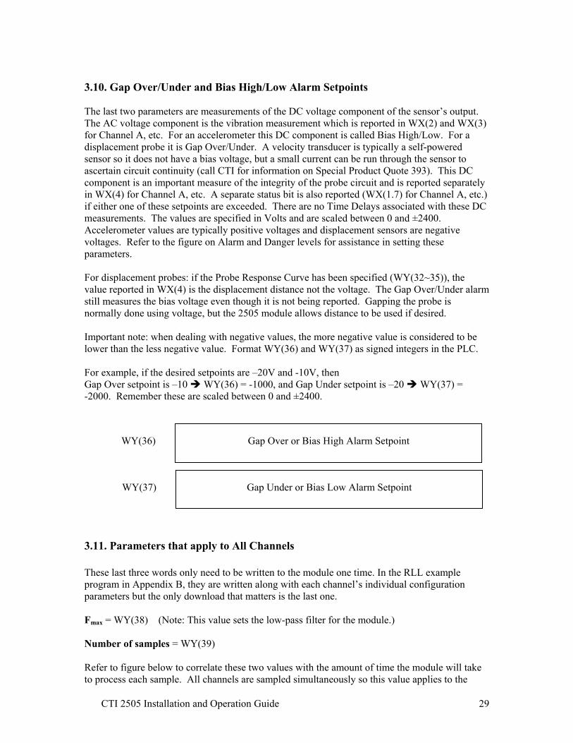
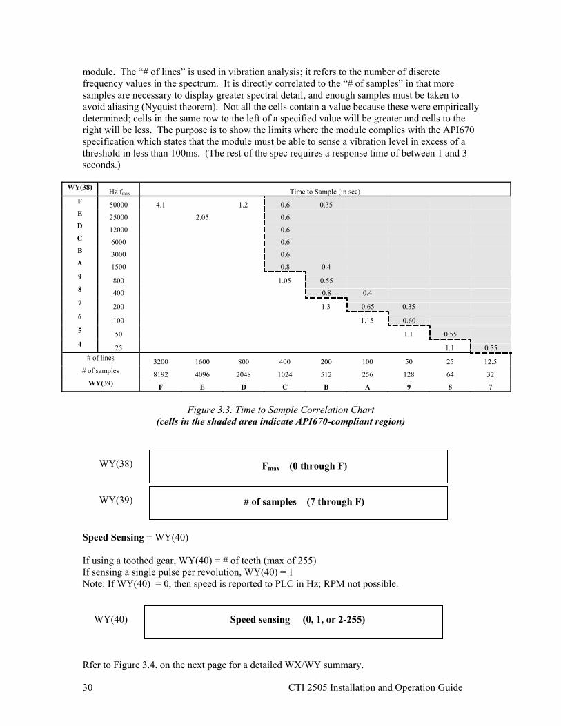
3.10. Gap Over/Under and Bias High/Low Alarm Setpoints The last two parameters are measurements of the DC voltage component of the sensor’s output. The AC voltage component is the vibration measurement which is reported in WX(2) and WX(3) for Channel A, etc. For an accelerometer this DC component is called Bias High/Low. For a displacement probe it is Gap Over/Under. A velocity transducer is typically a self-powered sensor so it does not have a bias voltage, but a small current can be run through the sensor to ascertain circuit continuity (call CTI for information on Special Product Quote 393). This DC component is an important measure of the integrity of the probe circuit and is reported separately in WX(4) for Channel A, etc. A separate status bit is also reported (WX(1.7) for Channel A, etc.) if either one of these setpoints are exceeded. There are no Time Delays associated with these DC measurements. The values are specified in Volts and are scaled between 0 and ±2400. Accelerometer values are typically positive voltages and displacement sensors are negative voltages. Refer to the figure on Alarm and Danger levels for assistance in setting these parameters. For displacement probes: if the Probe Response Curve has been specified (WY(32~35)), the value reported in WX(4) is the displacement distance not the voltage. The Gap Over/Under alarm still measures the bias voltage even though it is not being reported. Gapping the probe is normally done using voltage, but the 2505 module allows distance to be used if desired. Important note: when dealing with negative values, the more negative value is considered to be lower than the less negative value. Format WY(36) and WY(37) as signed integers in the PLC. For example, if the desired setpoints are –20V and -10V, then Gap Over setpoint is –10 WY(36) = -1000, and Gap Under setpoint is –20 WY(37) = -2000. Remember these are scaled between 0 and ±2400. 3.11. Parameters that apply to All Channels These last three words only need to be written to the module one time. In the RLL example program in Appendix B, they are written along with each channel’s individual configuration parameters but the only download that matters is the last one. Fmax = WY(38) (Note: This value sets the low-pass filter for the module.) Number of samples = WY(39) Refer to figure below to correlate these two values with the amount of time the module will take to process each sample. All channels are sampled simultaneously so this value applies to the
WY(37) Gap Under or Bias Low Alarm Setpoint
WY(36) Gap Over or Bias High Alarm Setpoint
CTI 2505 Installation and Operation Guide 30
module. The “# of lines” is used in vibration analysis; it refers to the number of discrete frequency values in the spectrum. It is directly correlated to the “# of samples” in that more samples are necessary to display greater spectral detail, and enough samples must be taken to avoid aliasing (Nyquist theorem). Not all the cells contain a value because these were empirically determined; cells in the same row to the left of a specified value will be greater and cells to the right will be less. The purpose is to show the limits where the module complies with the API670 specification which states that the module must be able to sense a vibration level in excess of a threshold in less than 100ms. (The rest of the spec requires a response time of between 1 and 3 seconds.)
WY(38) Hz fmax Time to Sample (in sec) F 50000 4.1 1.2 0.6 0.35 E 25000 2.05 0.6 D 12000 0.6 C 6000 0.6 B 3000 0.6 A 1500 0.8 0.4 9 800 1.05 0.55 8 400 0.8 0.4 7 200 1.3 0.65 0.35 6 100 1.15 0.60 5 50 1.1 0.55 4 25 1.1 0.55
# of lines 3200 1600 800 400 200 100 50 25 12.5 # of samples 8192 4096 2048 1024 512 256 128 64 32
WY(39) F E D C B A 9 8 7
Figure 3.3. Time to Sample Correlation Chart (cells in the shaded area indicate API670-compliant region)
Speed Sensing = WY(40) If using a toothed gear, WY(40) = # of teeth (max of 255) If sensing a single pulse per revolution, WY(40) = 1 Note: If WY(40) = 0, then speed is reported to PLC in Hz; RPM not possible.
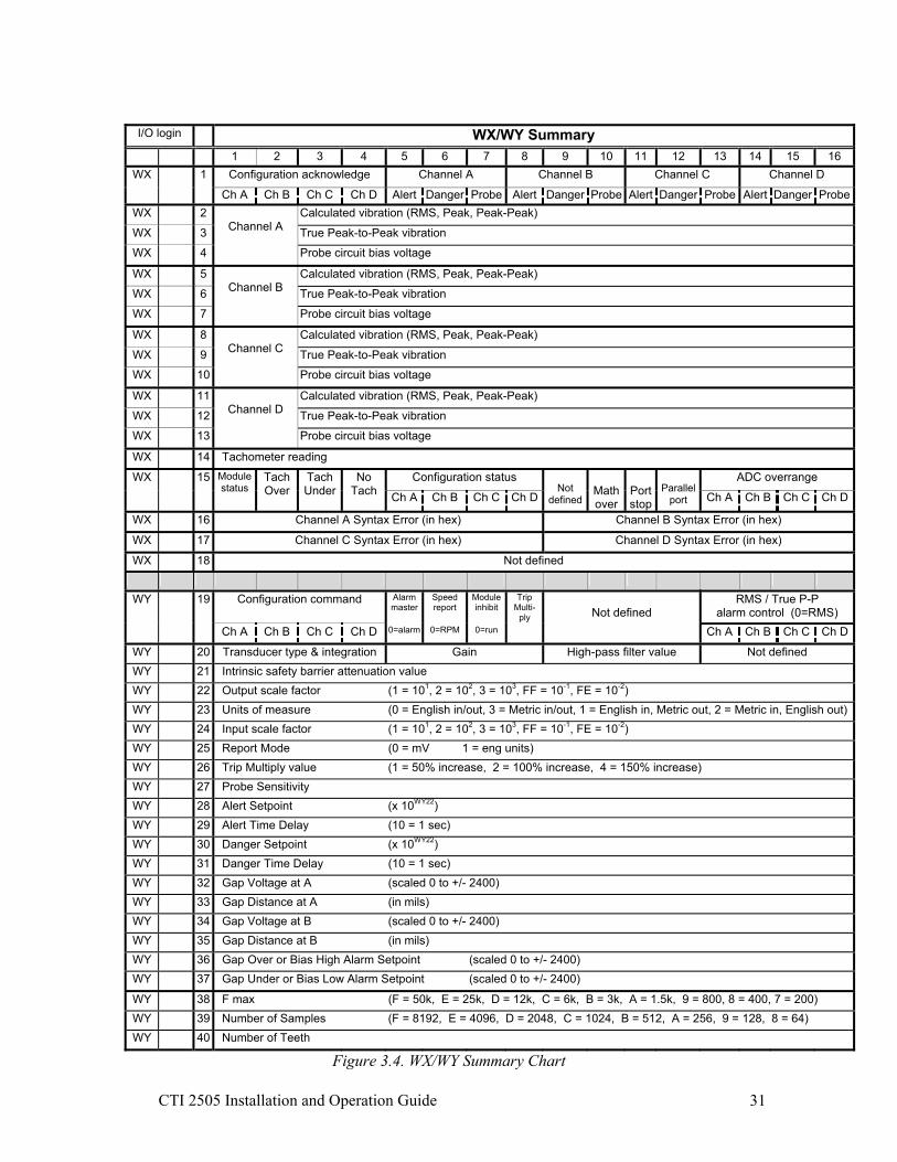
Rfer to Figure 3.4. on the next page for a detailed WX/WY summary.
Fmax (0 through F)
# of samples (7 through F)
WY(38)
WY(39)
Speed sensing (0, 1, or 2-255) WY(40)
CTI 2505 Installation and Operation Guide 31
I/O login 1 WX/WY Summary 1 2 3 4 5 6 7 8 9 10 11 12 13 14 15 16
WX 1 Configuration acknowledge Channel A Channel B Channel C Channel D
Ch A Ch B Ch C Ch D Alert Danger Probe Alert Danger Probe Alert Danger Probe Alert Danger ProbeWX 2 Calculated vibration (RMS, Peak, Peak-Peak)
WX 3 True Peak-to-Peak vibration
WX 4
Channel A
Probe circuit bias voltage
WX 5 Calculated vibration (RMS, Peak, Peak-Peak)
WX 6 True Peak-to-Peak vibration
WX 7
Channel B
Probe circuit bias voltage
WX 8 Calculated vibration (RMS, Peak, Peak-Peak)
WX 9 True Peak-to-Peak vibration
WX 10
Channel C
Probe circuit bias voltage
WX 11 Calculated vibration (RMS, Peak, Peak-Peak)
WX 12 True Peak-to-Peak vibration
WX 13
Channel D
Probe circuit bias voltage
WX 14 Tachometer reading
WX Configuration status ADC overrange
15 Module status
Tach Over
Tach Under
No Tach Ch A Ch B Ch C Ch D
Not
defined
Math over
Port stop
Parallel
port Ch A Ch B Ch C Ch D
WX 16 Channel A Syntax Error (in hex) Channel B Syntax Error (in hex)
WX 17 Channel C Syntax Error (in hex) Channel D Syntax Error (in hex)
WX 18 Not defined
WY 19 Configuration command Alarm master
Speed report
Module inhibit
Trip Multi-
ply
RMS / True P-P alarm control (0=RMS)
Ch A Ch B Ch C Ch D 0=alarm 0=RPM 0=run
Not defined
Ch A Ch B Ch C Ch D
WY 20 Transducer type & integration Gain High-pass filter value Not defined WY 21 Intrinsic safety barrier attenuation value WY 22 Output scale factor (1 = 101, 2 = 102, 3 = 103, FF = 10-1, FE = 10-2) WY 23 Units of measure (0 = English in/out, 3 = Metric in/out, 1 = English in, Metric out, 2 = Metric in, English out)WY 24 Input scale factor (1 = 101, 2 = 102, 3 = 103, FF = 10-1, FE = 10-2) WY 25 Report Mode (0 = mV 1 = eng units) WY 26 Trip Multiply value (1 = 50% increase, 2 = 100% increase, 4 = 150% increase) WY 27 Probe Sensitivity WY 28 Alert Setpoint (x 10WY22) WY 29 Alert Time Delay (10 = 1 sec) WY 30 Danger Setpoint (x 10WY22) WY 31 Danger Time Delay (10 = 1 sec) WY 32 Gap Voltage at A (scaled 0 to +/- 2400) WY 33 Gap Distance at A (in mils) WY 34 Gap Voltage at B (scaled 0 to +/- 2400) WY 35 Gap Distance at B (in mils) WY 36 Gap Over or Bias High Alarm Setpoint (scaled 0 to +/- 2400) WY 37 Gap Under or Bias Low Alarm Setpoint (scaled 0 to +/- 2400)
WY 38 F max (F = 50k, E = 25k, D = 12k, C = 6k, B = 3k, A = 1.5k, 9 = 800, 8 = 400, 7 = 200) WY 39 Number of Samples (F = 8192, E = 4096, D = 2048, C = 1024, B = 512, A = 256, 9 = 128, 8 = 64) WY 40 Number of Teeth
Figure 3.4. WX/WY Summary Chart

CTI 2505 Installation and Operation Guide 32
CTI 2505 Installation and Operation Guide 33
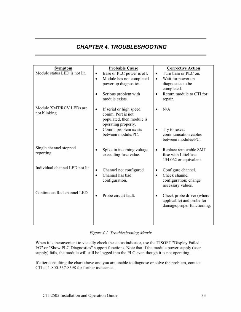
CHAPTER 4. TROUBLESHOOTING
Symptom
Module status LED is not lit. Module XMT/RCV LEDs are not blinking Single channel stopped reporting Individual channel LED not lit Continuous Red channel LED
Probable Cause • Base or PLC power is off. • Module has not completed
power up diagnostics. • Serious problem with
module exists. • If serial or high speed
comm. Port is not populated, then module is operating properly.
• Comm. problem exists between module/PC.
• Spike in incoming voltage
exceeding fuse value. • Channel not configured. • Channel has bad
configuration. • Probe circuit fault.
Corrective Action • Turn base or PLC on. • Wait for power up
diagnostics to be completed.
• Return module to CTI for repair.
• N/A • Try to reseat
communication cables between modules/PC.
• Replace removable SMT
fuse with Littelfuse 154.062 or equivalent.
• Configure channel. • Check channel
configuration; change necessary values.
• Check probe driver (where
applicable) and probe for damage/proper functioning.
Figure 4.1 Troubleshooting Matrix
When it is inconvenient to visually check the status indicator, use the TISOFT "Display Failed I/O" or "Show PLC Diagnostics" support functions. Note that if the module power supply (user supply) fails, the module will still be logged into the PLC even though it is not operating. If after consulting the chart above and you are unable to diagnose or solve the problem, contact CTI at 1-800-537-8398 for further assistance.

CTI 2505 Installation and Operation Guide 34

CTI 2505 Installation and Operation Guide 35
SPECIFICATIONS
Input Channels: 4 input channels plus tachometer Sensor Types: Accelerometer, Velocity, and Proximity Response Time: 4 mSec total module (includes settling time) Gain settings: 1, 1.25, 2.5, 5, 10, 25 High-pass filter values: 1, 2, 5, 10, 20, 50, 100 Hz PLC Reporting of: Overall RMS vibration level Peak-to-Peak value DC bias voltage of probe circuit Speed (in RPM or Hz) Probe Circuit Fault status bit Alarm/Danger status bits
Module status word Reporting units: mils, i.p.s., g’s, meters, m/s, m/s2 Isolation: 1500 VDC channel-to-PLC Backplane Power Consumption: up to 14.0 Watts Module Size: Double-wide Module (Packed) Weight: 2.0 lbs (0.9 kg) Operating Temperature: 0° to 60°C (32° to 140°F) Storage Temperature: -40° to 85°C (-40° to 185°F) Humidity, Relative: 5% to 95% non-condensing Agency Approvals Pending: UL, UL-C, FM (Class 1, Div 2), CE
Specifications subject to change without notice.

CTI 2505 Installation and Operation Guide 36

CTI 2505 Installation and Operation Guide 37
APPENDIX A. CONFIGURATION LOG SHEET
These two pages are provided for an easy record of each channel’s configuration setup. Make copies for each channel that is configured differently. Channel ___ Sensor type (accelerometer velocity displacement) Integrated (Yes No) Sensitivity __________________ Gain (1 1.25 2 5 10 25) High-pass filter setting (1 2 5 10 20 50 100) Report (RMS Peak Peak-Peak True P-P) Alarm on (none RMS True P-P) Parameters stored in V-memory at V________ Parameters stored in K-memory at K________ WY__ Hex __________________ Transducer Type & Integ. / Gain / HP Filter WY__ Sint __________________ Intrinsic Barrier Attenuation Factor WY__ Sint __________________ Output Scale Factor WY__ Sint __________________ Units of Measurement WY__ Sint __________________ Input Scale Factor WY__ Sint __________________ Reporting Mode WY__ Sint __________________ Trip Multiply Value WY__ Sint __________________ Probe Sensitivity WY__ Sint __________________ Alert Setpoint WY__ Sint __________________ Alert Time Delay WY__ Sint __________________ Danger Setpoint WY__ Sint __________________ Danger Time Delay WY__ Sint __________________ Gap Voltage at A WY__ Sint __________________ Gap Distance at A WY__ Sint __________________ Gap Voltage at B WY__ Sint __________________ Gap Distance at B WY__ Sint __________________ Gap Over or Bias High Alarm Setpoint WY__ Sint __________________ Gap Under or Bias Low Alarm Setpoint WY__ Hex __________________ Fmax WY__ Hex __________________ # of samples WY__ Sint __________________ # of gear teeth

CTI 2505 Installation and Operation Guide 38
CTI 2505 Installation and Operation Guide 39
APPENDIX B. SAMPLE LADDER LOGIC
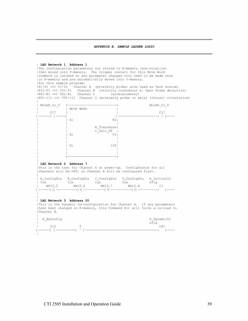
| LAD Network 1 Address 1 |The configuration parameters are stored in K-memory (non-volatile) |then moved into V-memory. The trigger contact for this Move Word |command is latched so any parameter changes only need to be made once |in K-memory and are automatically moved into V-memory. |For this sample program: |K1-21 ==> V1-21 Channel A (proximity probe; also used as Tach source) |K31-51 ==> V31-51 Channel B (velocity transducer w. Open Probe detection) |K61-81 ==> V61-81 Channel C (accelerometer) |K91-111 ==> V91-111 Channel D (proximity probe in axial (thrust) orientation) | | MoveK_to_V +-------------------------+ MoveK_to_V | | MOVE WORD | | C17 | | C17 [------] [-----] [--------------------( / )---- | | A: K1| | | | | | A_Transduce| | | r_Gain_HP | | | B: V1| | | | | | | | | N: 120| | | | | | | | +-------------------------+ | | LAD Network 2 Address 7 |This is the test for Channel A at power-up. ConfigStatus for all |channels will be OFF, so Channel A will be configured first. | | A_ConfigSta B_ConfigSta C_ConfigSta D_ConfigSta A_InitialCo | tus tus tus tus nfig | WX15.5 WX15.6 WX15.7 WX15.8 C1 [------]/[-----------]/[-----------]/[-----------]/[----------( )---- | | | LAD Network 3 Address 20 |This is the Dynamic re-configuration for Channel A. If any parameters |have been changed in K-memory, this Command Bit will force a re-load to |Channel A. | | A_ReConfig A_DynamicCo | nfig | C13 5 C81 [------] [----------] ^ [-------------------------------------( )---- |

CTI 2505 Installation and Operation Guide 40
| | LAD Network 4 Address 23 |This Move Word takes configuration parameters for Channel A from |V-memory to WY, then sets the Channel A configuration command bit (WY19.1). |Either the initial power-up or the dynamic reconfiguration can trigger this |command. The Configuration Acknowledge bit (WX1.1) is tested to keep the |command from executing more than once per download operation. | | A_InitialCo A_Config_X +-------------------------+ A_Config_Y | nfig | MOVE WORD | | C1 WX1.1 | A_Transduce| WY19.1 [------] [----+------]/[-----] r_Gain_HP [------( )---- | | | A: V1| | A_DynamicCo | | | | nfig | | Transducer_| | C81 | | Gain_HP | [------] [----] | B: WY20| | | | | | A_Config_Y | | | | | | N: 21| | WY19.1 | | | [------] [----+ | | | +-------------------------+ | | LAD Network 5 Address 38 |This is the test for Channel B at power-up. ConfigStatus for Channel A |will be ON, but Channel B, C, and D will still be OFF. | | A_ConfigSta B_ConfigSta C_ConfigSta D_ConfigSta B_InitialCo | tus tus tus tus nfig | WX15.5 WX15.6 WX15.7 WX15.8 C2 [------] [-----------]/[-----------]/[-----------]/[----------( )---- | | | LAD Network 6 Address 51 |This is the Dynamic re-configuration for Channel B. If any parameters |have been changed in K-memory, this Command Bit will force a re-load to |Channel B. | | B_ReConfig B_DynamicCo | nfig | C14 6 C82 [------] [----------] ^ [-------------------------------------( )---- | | | LAD Network 7 Address 54 |This Move Word takes configuration parameters for Channel B from V-memory |to WY, then sets the Channel B configuration command bit (WY19.2). Either |the initial power-up or the dynamic reconfiguration can trigger this command. |The Configuration Acknowledge bit (WX1.2) is tested to keep the command |from executing more than once per download operation. | B_InitialCo B_Config_X +-------------------------+ B_Config_Y | nfig | MOVE WORD | | C2 WX1.2 | B_Transduce| WY19.2 [------] [----+------]/[-----] r_Gain_HP [------( )---- | | | A: V31| | B_DynamicCo | | | | nfig | | Transducer_| | C82 | | Gain_HP | [------] [----] | B: WY20| | | | | | B_Config_Y | | | | | | N: 21| | WY19.2 | | | [------] [----+ | | | +-------------------------+

CTI 2505 Installation and Operation Guide 41
| | LAD Network 8 Address 69 |This is the test for Channel C at power-up. ConfigStatus for Channel A |and B will be ON, but Channel D will still be OFF. | | A_ConfigSta B_ConfigSta C_ConfigSta D_ConfigSta C_InitialCo | tus tus tus tus nfig | WX15.5 WX15.6 WX15.7 WX15.8 C3 [------] [-----------] [-----------]/[-----------]/[----------( )---- | | | LAD Network 9 Address 82 |This is the Dynamic re-configuration for Channel C. If any parameters |have been changed in K-memory, this Command Bit will force a re-load to |Channel C. | | C_ReConfig C_DynamicCo | nfig | C15 7 C83 [------] [----------] ^ [-------------------------------------( )---- | | | LAD Network 10 Address 85 |This Move Word takes configuration parameters for Channel C from V-memory to |WY, then sets the Channel C configuration command bit (WY19.3). Either the |initial power-up or the dynamic reconfiguration can trigger this command. |The Configuration Acknowledge bit (WX1.3) is tested to keep the command |from executing more than once per download operation. | | C_InitialCo C_Config_X +-------------------------+ C_Config_Y | nfig | MOVE WORD | | C3 WX1.3 | C_Transduce| WY19.3 [------] [----+------]/[-----] r_Gain_HP [------( )---- | | | A: V61| | C_DynamicCo | | | | nfig | | Transducer_| | C83 | | Gain_HP | [------] [----] | B: WY20| | | | | | C_Config_Y | | | | | | N: 21| | WY19.3 | | | [------] [----+ | | | +-------------------------+ | | LAD Network 11 Address 100 |This is the test for Channel D at power-up. ConfigStatus for all other |channels will be ON, but Channel D will still be OFF. | | A_ConfigSta B_ConfigSta C_ConfigSta D_ConfigSta D_InitialCo | tus tus tus tus nfig | WX15.5 WX15.6 WX15.7 WX15.8 C4 [------] [-----------] [-----------] [-----------]/[----------( )---- | | | LAD Network 12 Address 113 |This is the Dynamic re-configuration for Channel D. If any parameters |have been changed in K-memory, this Command Bit will force a re-load to |Channel D. | | D_ReConfig D_DynamicCo | nfig | C16 8 C84 [------] [----------] ^ [-------------------------------------( )---- |

CTI 2505 Installation and Operation Guide 42
| | LAD Network 13 Address 116 |This Move Word takes configuration parameters for Channel D from V-memory |to WY, then sets the Channel D configuration command bit (WY19.4). Either |the initial power-up or the dynamic reconfiguration can trigger this command. |The Configuration Acknowledge bit (WX1.4) is tested to keep the command |from executing more than once per download operation. | | D_InitialCo D_Config_X +-------------------------+ D_Config_Y | nfig | MOVE WORD | | C4 WX1.4 | D_Transduce| WY19.4 [------] [----+------]/[-----] r_Gain_HP [------( )---- | | | A: V91| | D_DynamicCo | | | | nfig | | Transducer_| | C84 | | Gain_HP | [------] [----] | B: WY20| | | | | | D_Config_Y | | | | | | N: 21| | WY19.4 | | | [------] [----+ | | | +-------------------------+ | | LAD Network 14 Address 131 |This AlarmMode command bit chooses whether the module performs the alarm tests. |The default value of 0 tells the module to test the channels for alarm levels |and set the appropriate status bits in WX1. If AlarmControl is set to 1, |the module ignores any alarm settings; status bits remain at 0 and the |front panel LEDs do not indicate alarm status. | | AlarmMode AlarmContro | lBit | C5 WY19.5 [------] [----------------------------------------------------( )---- | | | LAD Network 15 Address 135 |SpeedReport command bit chooses whether the Tach value reported in WX14 |is in Hz or RPM. Default of 0 is RPM; 1 chooses Hz (RPM / 60). The |notted contact in this sample program is indicating Hz. | | SpeedReport TachReportM | ode | C6 WY19.6 [------]/[----------------------------------------------------( )---- | | | LAD Network 16 Address 139 |The ModuleInhibit bit (WY19.7) forces the module to cease all processing; |WX data words will be held at last value. This rung is conditioning the |ModuleInhibit by Module Status, e.g. the module must be functioning to be |inhibited. The default of 0 is the Run condition. | | ModuleInhib ModuleStatu Inhibit | it s | C7 WX15.1 WY19.7 [------] [-----------] [--------------------------------------( )---- | | | LAD Network 17 Address 146 |The TripMultiply command bit from the PLC / operator tells the module |to take each channel’s alarm levels to the Trip Multiply settings |specified in the channel’s configuration parameters. When TripMultiply |is released (back to 0 value) then each channel reverts to normal alarm levels. | | TripMultipl TripMultipl | yCtrl y | C8 WY19.8 [------] [----------------------------------------------------( )---- |

CTI 2505 Installation and Operation Guide 43
| | LAD Network 18 Address 150 |This command bit for Channel A chooses whether processing of the alarm |values for Alert and Danger specified in the configuration parameters |is done on the RMS value (reported in WX2) or the True Peak-Peak value |(reported in WX3). Default of 0 is RMS. | | A_PeakPeak A_AlarmChoi | ce | C9 WY19.13 [------] [----------------------------------------------------( )---- | | | LAD Network 19 Address 154 |This command bit for Channel B chooses whether processing of the alarm |values for Alert and Danger specified in the configuration parameters |is done on the RMS value (reported in WX5) or the True Peak-Peak value |(reported in WX6). Default of 0 is RMS. | | B_PeakPeak B_AlarmChoi | ce | C10 WY19.14 [------] [----------------------------------------------------( )---- | | LAD Network 20 Address 158 |This command bit for Channel C chooses whether processing of the alarm |values for Alert and Danger specified in the configuration parameters |is done on the RMS value (reported in WX8) or the True Peak-Peak value |(reported in WX9). Default of 0 is RMS. | | C_PeakPeak C_AlarmChoi | ce | C11 WY19.15 [------] [----------------------------------------------------( )---- | | | LAD Network 21 Address 162 |This command bit for Channel D chooses whether processing of the alarm |values for Alert and Danger specified in the configuration parameters |is done on the RMS value (reported in WX11) or the True Peak-Peak value |(reported in WX12). Default of 0 is RMS. |This example program has a proximity probe in an axial orientation to |measure the shaft movement due to thrust. The AC component of vibration |is not as critical as the true movement, so the True Peak-to-Peak value |is selected for alarming. | | D_PeakPeak D_AlarmChoi | ce | C12 WY19.16 [------]/[----------------------------------------------------( )---- | | | LAD Network 22 Address 166 |This rung is continually testing for axial shaft movement due to thrust. |Assume the shaft at rest was gapped to -10V with a 200mV/mil proximity probe. |Test the DC Probe bias voltage for Channel D (WX13) for movement of 20mils |(4V change) in positive direction and 10mils (2V change) in negative direction. | | +--A > B------------------+ AxialThrust | |D_ProbeCirc | Alarm | C25 |uitVoltage | C26 [------]/[---+-] A: WX13 B: -14[-+-------------------( )---- | | +-------------------------+ | | | | | | +--A < B------------------+ | | | |D_ProbeCirc | | | | |uitVoltage | | | +-] A: WX13 B: -8[-+ | +-------------------------+ | | +-------------+ [---------------------------+ PROGRAM END +---------------------------- | +-------------+

CTI 2505 Installation and Operation Guide 44
REGISTERS V REGISTERS: V1 - V50120 Address Value Tag Address Value Tag V1 00768 A_Transduce V26 00000 r_Gain_HP V2 00000 A_IS_Barrie V27 00000 r V3 00000 A_OutputSca V28 00000 leFactor V4 00000 A_UnitsOfMe V29 00000 asure V5 00000 A_InputScal V30 00000 eFactor V6 00000 A_ReportMod V31 00768 B_Transduce e r_Gain_HP V7 00000 A_TripMulti V32 00000 B_IS_Barrie plyValue r V8 00100 A_ProbeSens V33 00000 B_OutputSca itivity leFactor V9 00030 A_AlertSetp V34 00000 B_UnitsOfMe oint asure V10 00030 A_AlertTime V35 00000 B_InputScal Delay eFactor V11 00040 A_DangerSet V36 00000 B_ReportMod point e V12 00040 A_DangerTim V37 00000 B_TripMulti eDelay plyValue V13 00000 A_GapVoltag V38 00100 B_ProbeSens eA itivity V14 00000 A_GapDistan V39 00030 B_AlertSetp ceA oint V15 00000 A_GapVoltag V40 00030 B_AlertTime eB Delay V16 00000 A_GapDistan V41 00040 B_DangerSet ceB point V17 01500 A_GapOver_B V42 00040 B_DangerTim iasHigh_Ala eDelay V18 00800 A_GapUnder_ V43 00000 B_GapVoltag BiasLow_Ala eA V19 00004 A_Fmax V44 00000 B_GapDistan ceA V20 00007 A_NumberOfS V45 00000 B_GapVoltag amples eB V21 00025 A_NumberOfT V46 00000 B_GapDistan eeth ceB V22 00000 V47 01500 B_GapOver_B iasHigh_Ala V23 00000 V48 00800 B_GapUnder_ BiasLow_Ala V24 00000 V49 00010 B_Fmax V25 00000 V50 00013 B_NumberOfS amples
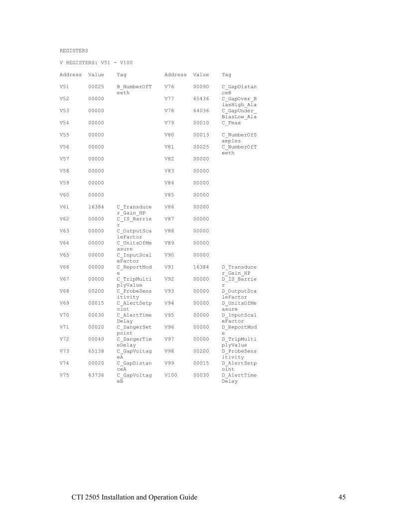
CTI 2505 Installation and Operation Guide 45
REGISTERS V REGISTERS: V51 - V100 Address Value Tag Address Value Tag V51 00025 B_NumberOfT V76 00090 C_GapDistan eeth ceB V52 00000 V77 65436 C_GapOver_B iasHigh_Ala V53 00000 V78 64036 C_GapUnder_ BiasLow_Ala V54 00000 V79 00010 C_Fmax V55 00000 V80 00013 C_NumberOfS amples V56 00000 V81 00025 C_NumberOfT eeth V57 00000 V82 00000 V58 00000 V83 00000 V59 00000 V84 00000 V60 00000 V85 00000 V61 16384 C_Transduce V86 00000 r_Gain_HP V62 00000 C_IS_Barrie V87 00000 r V63 00000 C_OutputSca V88 00000 leFactor V64 00000 C_UnitsOfMe V89 00000 asure V65 00000 C_InputScal V90 00000 eFactor V66 00000 C_ReportMod V91 16384 D_Transduce e r_Gain_HP V67 00000 C_TripMulti V92 00000 D_IS_Barrie plyValue r V68 00200 C_ProbeSens V93 00000 D_OutputSca itivity leFactor V69 00015 C_AlertSetp V94 00000 D_UnitsOfMe oint asure V70 00030 C_AlertTime V95 00000 D_InputScal Delay eFactor V71 00020 C_DangerSet V96 00000 D_ReportMod point e V72 00040 C_DangerTim V97 00000 D_TripMulti eDelay plyValue V73 65138 C_GapVoltag V98 00200 D_ProbeSens eA itivity V74 00020 C_GapDistan V99 00015 D_AlertSetp ceA oint V75 63736 C_GapVoltag V100 00030 D_AlertTime eB Delay

CTI 2505 Installation and Operation Guide 46
REGISTERS V REGISTERS: V101 - V120 Address Value Tag V101 00020 D_DangerSet point V102 00040 D_DangerTim eDelay V103 65138 D_GapVoltag eA V104 00020 D_GapDistan ceA V105 63736 D_GapVoltag eB V106 00090 D_GapDistan ceB V107 65436 D_GapOver_B iasHigh_Ala V108 64036 D_GapUnder_ BiasLow_Ala V109 00008 D_Fmax V110 00008 D_NumberOfS amples V111 00025 D_NumberOfT eeth V112 00000 V113 00000 V114 00000 V115 00000 V116 00000 V117 00000 V118 00000 V119 00000 V120 00000

CTI 2505 Installation and Operation Guide 47
DOCUMENTATION Addr Tag Addr Tag Addr Tag C1 A_InitialCo WX1.5 A_Alert WX12 D_TruePeak_ nfig peak WX1.6 A_Danger C2 B_InitialCo WX13 D_ProbeCirc nfig WX1.7 A_ProbeFaul uitVoltage t C3 C_InitialCo WX14 TachData nfig WX1.8 B_Alert WX15 Module_stat C4 D_InitialCo WX1.9 B_Danger us_word nfig WX1.10 B_ProbeFaul WX15.1 ModuleStatu C5 AlarmMode t s C6 SpeedReport WX1.11 C_Alert WX15.2 TachOverran ge C7 ModuleInhib WX1.12 C_Danger it WX15.3 TachUnderra WX1.13 C_ProbeFaul nge C8 TripMultipl t yCtrl WX15.4 NoTach WX1.14 D_Alert C9 A_PeakPeak WX15.5 A_ConfigSta WX1.15 D_Danger tus C10 B_PeakPeak WX1.16 D_ProbeFaul WX15.6 B_ConfigSta C11 C_PeakPeak t tus C12 D_PeakPeak WX2 A_RMS WX15.7 C_ConfigSta tus C13 A_ReConfig WX3 A_TruePeak_ peak WX15.8 D_ConfigSta C14 B_ReConfig tus WX4 A_ProbeCirc C15 C_ReConfig uitVoltage WX15.10 MathOverflo w C16 D_ReConfig WX5 B_RMS WX15.11 PortStop C17 MoveK_to_V WX6 B_TruePeak_ peak WX15.12 ParallelPor C26 AxialThrust tTimeout Alarm WX7 B_ProbeCirc uitVoltage WX15.13 A_ADC_Overr WX1 ConfigAcks_ ange AlarmBits WX8 C_RMS WX15.14 B_ADC_Overr WX1.1 A_Config_X WX9 C_TruePeak_ ange peak WX1.2 B_Config_X WX15.15 C_ADC_Overr WX10 C_ProbeCirc ange WX1.3 C_Config_X uitVoltage WX15.16 D_ADC_Overr WX1.4 D_Config_X WX11 D_RMS ange

CTI 2505 Installation and Operation Guide 48
DOCUMENTATION Addr Tag Addr Tag Addr Tag WX16 A_B_SyntaxE WY20 Transducer_ WY39 NumberOfSam rror Gain_HP ples WX17 C_D_SyntaxE WY21 IS_Barrier WY40 NumberOfTee rror th WY22 OutputScale WX19.5 AlarmContro Factor l WY23 UnitsOfMeas WX19.6 SpeedReport ure Mode WY24 InputScaleF WX19.7 RunMode actor WX19.8 TripMultipl WY25 ReportMode yMode WY26 TripMultipl WY19 ConfigCmd_M yValue oduleContro l WY27 ProbeSensit ivity WY19.1 A_Config_Y WY28 AlertSetpoi WY19.2 B_Config_Y nt WY19.3 C_Config_Y WY29 AlertTimeDe lay WY19.4 D_Config_Y WY30 DangerSetpo WY19.5 AlarmContro int lBit WY31 DangerTimeD WY19.6 TachReportM elay ode WY32 GapVoltageA WY19.7 Inhibit WY33 GapDistance WY19.8 TripMultipl A y WY34 GapVoltageB WY19.13 A_AlarmChoi ce WY35 GapDistance B WY19.14 B_AlarmChoi ce WY36 GapOver_Bia sHigh_Alarm WY19.15 C_AlarmChoi ce WY37 GapUnder_Bi asLow_Alarm WY19.16 D_AlarmChoi ce WY38 F_max

CTI 2505 Installation and Operation Guide 49
APPENDIX C. CONFIGURATION: STATUS AND TIMING FOR COMMAND/ACKNOWLEDGE
A: Power up self diagnostics passed; channel configuration status = 0 indicates no
parameters loaded for that channel. PLC program sets configuration command control bit (WY19.1=1) which initiates transfer of parameters (WY20~40) to module.
B: Module responds by setting configuration acknowledge (WX1.1=1) when data has been checked for valid syntax and database successfully updated. If syntax check fails, the acknowledge bit is not set and the word that caused the error is reported in Syntax Error (WX16 high byte for Ch A).
C: PLC program resets configuration command bit (WX19.1=0). D: Module responds by resetting configuration acknowledge bit (WX1.1=0) and setting
configuration status (WX15.5=1) to indicate successful configuration. Note that the parameters can be reloaded at anytime even though configuration status is set.
WX15.5 Ch A Configuration Status WY19.1 Configuration Command WX1.1 Configuration Acknowledge WX15.6 Ch B Configuration Status WY19.2 Configuration Command WX1.2 Configuration Acknowledge
WX15.7 Ch C Configuration Status WY19.3 Configuration Command WX1.3 Configuration Acknowledge WX15.8 Ch D Configuration Status WY19.4 Configuration Command WX1.4 Configuration Acknowledge
WX1.1
WY19.1
Configuration status: Ch A not configured
Config acknowledge
Config command
WX15.5 Configuration successful
Power up self diags
A B C D

CTI 2505 Installation and Operation Guide 50
Status Words WX1 bits 1~4 Configuration acknowledge for Channels A~D bits 5~7 Alarm status bits for Channel A bits 8~10 Alarm status bits for Channel B bits 11~13 Alarm status bits for Channel C bits 14~16 Alarm status bits for Channel D WX15 bit 1 Module status bit 1 = passed self-diags [Module LED solid Green] 0 = failed self-diags [Module LED off] bit 2 Tachometer Overrange 1 = tach input signal > 65535 Hz bit 3 Tachometer Underrange 1 = tach input < 2Hz
bit 4 No Tach 1 = no input pulses within 10 seconds
bit 5 Channel A configuration status bit 1 = configuration downloaded & syntax OK [Channel LED solid Green] 0 = not configured or configuration bad [Channel LED off]
bit 6 Channel B bit 7 Channel C bit 8 Channel D bit 9 Not defined
bit 10 Math Overflow 1 = a reported value is outside the signed integer range bit 11 Port Stop 1 = either Serial or Parallel port stopped the data acquisition process bit 12 Parallel Port Timeout 1 = 2506 failed to respond to STROBE or a BUS_BUSY signal bit 13 Channel A Analog-Digital Converter overrange bit 1 = set when input reading saturates ADC => Gain setting too high bit 14 Channel B
bit 15 Channel C bit 16 Channel D
WX16 high byte Channel A syntax error; displays (in hex) WY word that caused syntax error
e.g. 20xx = error in WY20 … first configuration Word Note: These are referenced to WY20 even though I/O login may be different.
low byte Channel B syntax error WX17 high byte Channel C syntax error low byte Channel D syntax error

CTI 2505 Installation and Operation Guide 51
Control Bits WY19 bit 1 Channel A configuration command bit
1 = initiate download of parameters from PLC to module bit 2 Channel B bit 3 Channel C bit 4 Channel D
bit 5 Alarm Master 0 = module calculates Alert / Danger; provides analog values and status to PLC
1 = module provides analog values only bit 6 Speed Report
1 = report speed in Hz (max of 65k) 0 = report speed in RPM bit 7 Module Inhibit 1 = do not process input signals & freeze outputs at current levels bit 8 Trip Multiply 1 = process alarms at Setpoint value x Trip Multiply value bit 9 Not defined bit 10 Not defined bit 11 Not defined bit 12 Not defined bit 13 Channel A RMS or True P-P alarm choice 1 = process alarms on value contained in WX3 (True Peak-to-Peak) 0 = process alarms on value contained in WX2 (Calculated RMS) bit 14 Channel B bit 15 Channel C bit 16 Channel D Analog Values WX2 Channel A calculated vibration
* in mVolts or eng units (dependent on value in WY25)
WX3 Channel A True Peak-to-Peak vibration * in mVolts or eng units (dependent on value in WY25) WX4 Channel A Probe circuit bias voltage
* DC voltage of probe circuit (scaled from 0 to ±2400) * if Displacement probe and WY32~35 are non-zero: displacement in mils or um
(Scaled to WY22) (Note: Probe Bias Alarm still operates on bias voltage.)
WX5 ~ 7 Channel B WX8 ~ 10 Channel C WX11 ~ 13 Channel D WX14 tachometer input in RPM or Hz (dependent on WY19.6)

CTI 2505 Installation and Operation Guide 52
LIMITED PRODUCT WARRANTY
CTI warrants that this CTI Industrial Product shall be free from defects in material and workmanship for a period of one (1) year after purchase from CTI or from an authorized CTI Industrial Distributor. This CTI Industrial Product will be newly manufactured from new and/or serviceable used parts which are equal to new in the Product. Should this CTI Industrial Product fail to be free from defects in material and workmanship at any time during this (1) year warranty period, CTI will repair or replace (at its option) parts or Products found to be defective and shipped prepaid by the customer to a designated CTI service location along with proof of purchase date and associated serial number. Repair parts and replacement Product furnished under this warranty will be on an exchange basis and will be either reconditioned or new. All exchanged parts or Products become the property of CTI. Should any Product or part returned to CTI hereunder be found by CTI to be without defect, CTI will return such Product or part to the customer. This warranty does not include repair of damage to a part or Product resulting from: failure to provide a suitable environment as specified in applicable Product specifications, or damage caused by an accident, disaster, acts of God, neglect, abuse, misuse, transportation, alterations, attachments, accessories, supplies, non-CTI parts, non-CTI repairs or activities, or to any damage whose proximate cause was utilities or utility like services, or faulty installation or maintenance done by someone other than CTI. Control Technology Inc. reserves the right to make changes to the Product in order to improve reliability, function, or design in the pursuit of providing the best possible Product. CTI assumes no responsibility for indirect or consequential damages resulting from the use or application of this equipment. THE WARRANTY SET FORTH ABOVE IN THIS ARTICLE IS THE ONLY WARRANTY CTI GRANTS AND IT IS IN LIEU OF ANY OTHER IMPLIED OR EXPRESSED GUARANTY OR WARRANTY ON CTI PRODUCTS, INCLUDING WITHOUT LIMITATION, ANY WARRANTY OF MERCHANTABILITY OR OF FITNESS FOR A PARTICULAR PURPOSE AND IS IN LIEU OF ALL OBLIGATIONS OR LIABILITY OF CTI FOR DAMAGES IN CONNECTION WITH LOSS, DELIVERY, USE OR PERFORMANCE OF CTI PRODUCTS OR INTERRUPTION OF BUSINESS, LOSS OF USE, REVENUE OR PROFIT. IN NO EVENT WILL CTI BE LIABLE FOR SPECIAL, INCIDENTAL, OR CONSEQUENTIAL DAMAGES. SOME STATES DO NOT ALLOW THE EXCLUSION OR LIMITATION OF INCIDENTAL OR CONSEQUENTIAL DAMAGES FOR CONSUMER PRODUCTS, SO THE ABOVE LIMITATIONS OR EXCLUSIONS MAY NOT APPLY TO YOU. THIS WARRANTY GIVES YOU SPECIFIC LEGAL RIGHTS, AND YOU MAY ALSO HAVE OTHER RIGHTS WHICH MAY VARY FROM STATE TO STATE.

CTI 2505 Installation and Operation Guide 53
REPAIR POLICY
In the event that the Product should fail during or after the warranty period, a Return Material Authorization (RMA) number can be requested orally or in writing from CTI main offices. Whether this equipment is in or out of warranty, a Purchase Order number provided to CTI when requesting the RMA number will aid in expediting the repair process. The RMA number that is issued and your Purchase Order number should be referenced on the returning equipment's shipping documentation. Additionally, if the product is under warranty, proof of purchase date and serial number must accompany the returned equipment. The current repair and/or exchange rates can be obtained by contacting CTI's office at 1-800-537-8398. When returning any module to CTI, follow proper static control precautions. Keep the module away from polyethylene products, polystyrene products and all other static producing materials. Packing the module in its original conductive bag is the preferred way to control static problems during shipment. Failure to observe static control precautions may void the warranty. For additional information on static control precautions, contact CTI's office at 1-800-537-8398.

CTI 2505 Installation and Operation Guide 54