25 Kv ac ELECTRIFICATION PROJECT ASSESSMENT OF …mly/Caltrain-Electrification/rolling.pdf · 25 Kv...
55
25 Kv ac ELECTRIFICATION PROJECT ASSESSMENT OF ELECTRIC MULTIPLE UNITS PASSENGER RAIL CARS
Transcript of 25 Kv ac ELECTRIFICATION PROJECT ASSESSMENT OF …mly/Caltrain-Electrification/rolling.pdf · 25 Kv...

25 Kv ac ELECTRIFICATION PROJECT
ASSESSMENT OF ELECTRIC MULTIPLE UNITS
PASSENGER RAIL CARS

TABLE OF CONTENTS
EXECUTIVE SUMMARY
1. BACKGROUND AND INTRODUCTION
2. ASSUMPTIONS AND APPROACH
3. REFERENCE SOURCES
4. JAPANESE TECHNOLOGY
4.1 Japanese Double Deck EMU
4.1.1 Mechanical Characteristics
4.1.2 Propulsion System
4.1.3 Traction Transformer
4.1.4 Converters
4.1.5 Inverters
4.1.6 Controls
4.1.7 Traction Motor
4.1.8 Suppliers
5. EUROPEAN TECHNOLOGY
5.1 European Bi-level EMUs
5.1.1 Mechanical Characteristics
5.1.2 Propulsion Systems
5.1.3 Interior Arrangements and Passenger Comfort and Amenities
5.2 TER 2N
5.3 TAF
5.4 Siemens
5.5 Adtranz

6. U.S. TECHNOLOGY
6.1 M-7 Long Island Railroad System
6.1.1 Train Description
6.1.2 Car Propulsion System Configuration
6.1.3 Inverter
6.1.4 Propulsion Controller
6.1.5 Traction Motor
6.1.6 Gear Unit
6.1.7 Circuit Protection Box
6.1.8 Brake Resistor
6.1.9 Passenger Accommodations and Amenities
6.2 NICTD System
7. U.S. RULES AND REGULATIONS AND RECOMMENDED INDUSTRY PRACTICES
8. CONCLUSIONS AND RECOMMENDATIONS

JPBEMUReport 1 December 2000
EXECUTIVE SUMMARY
The Peninsula Corridor Joint Powers Board (PCJPB) has determined to electrify the rail line
utilized by its commuter rail operations. This particular document reports on the results of a
research and evaluation of Electric Multiple Unit (EMU) passenger rail cars and is prepared for
the purpose of augmenting a previous evaluation of rolling stock equipment focusing on
electrically powered locomotive technology.
Two major assumptions were defined early in the process in order to focus on realistic
alternatives. The assumptions were: a) that the cars should be of multi-level design, taking full
advantage of existing railroad clearances and increasing system capacity; and b) that the
equipment must be designed and built in accordance with all current U.S. Rules and
Regulations and Recommended Industry Practices.
Japanese and European equipment were identified and evaluated. While European countries
have adopted multi-level EMU cars for commuter services, the Japanese have concentrated on
applying the technology to intercity services, meaning higher operating speeds and more
comfortable accommodations, such as fully reclining seats and food service equipment, among
others. For that reason, this report presents the assessment of these two vehicle technologies
from a slightly different point of view, although both are oriented toward the same goals and
objectives. More specifically the evaluation of these technologies is intended to determine the
applicability of these vehicle and components and/or systems in the technical and regulatory
railroad environment in force in the United States.
With regard to European Technologies the report focuses primarily on three modern vehicle
technologies in operation or under development, namely the French TER 2N, by Alstom and
Bombardier for the French National Railways; the Italian TAF, by Ansaldo-Breda for the newly
formed TrenItalia (formerly the Italian National Railways); and the Swiss IC2000 by Adtranz, for
the Regional Commuter Rail Authority in Zurich. These three technologies were selected among
many others, as the most modern and representative in Europe and most likely to be adapted to
the Caltrain services. Also, because they offer the most modern facilities for passenger comfort
and safety, with wide entrance doors, low boarding floors, optimum passenger flow through
doors, aisleways and stairways, excellent lighting and comfortable 2+2 seats.
All three technologies are basically arranged in the same form, including power, cab and trailer
cars. The power equipment occupies the “mezzanine” level of the floor over the trucks, at one
end of the car. Passenger seating accommodations are arranged in the low floor section,
between the trucks; on the upper floor and in the “mezzanine” level at the opposite end of the
car. The control cab for push-pull operations is arranged at one end of the non-powered car. A

JPBEMUReport 2 December 2000
third car design, a trailer, is available to be coupled between a powered and a cab car, but this
consist is rarely used in typical European formations due to acceleration and braking
requirements.
The arrangement of the power equipment, floor and stairway layouts, side door location and
size and overall dimensions of the cars are features that should be further evaluated for
application to the future Caltrain equipment.
With regard to Japanese equipment, the most recent bi-level passenger cars in operation are
oriented toward intercity services. Japanese Railway clearances are more generous than those
found in the general system of railroads in the U.S., allowing for car bodies six to twelve inches
wider. In addition, the structure of the car body is not designed in accordance with U.S.
requirements; therefore it is not appropriate to consider these mechanical systems for
application in the Caltrain services. As with European equipment, however, a number of other
systems, components and equipment offer significant technical and economic potential benefits
and should be evaluated in more detail.
We also evaluated technologies recently or currently being implemented in the U.S. While these
technologies are not of U.S. origin, they are being adapted to the overall railroad environment,
rules and regulations. Two recent EMU procurements are discussed, including the M7 cars for
the Long Island Railroad and the Nippon-Sharyo cars for NICTD. Both cars are single level.
The conclusions are that indeed both European and Japanese manufacturers are highly
capable and qualified to supply rolling stock equipment to the U.S. market, in accordance with
all applicable rules, regulations and recommended practices
However, a word of caution must be expressed, with regard to new developments. For it to be
successfully implemented, the following must occur:
• the problem to be solved must be correctly identified. A common occurrence is to find a
solution, not knowing what the problem really is;
• correct definition of system performance;
• clearly and reasonably written performance specifications and contractual terms and
conditions;
• realistic schedules that allow for development, testing and commissioning;
• a true partnership relationship between the customer and the contractor.
Recent problems with the implementation of high-speed services in the Northeast corridor must
be used as a constructive experience and not repeat them.
JPBEMUReport 3 December 2000
In addition, it must be remembered that vehicle prices will depend on the total number of cars
ordered. Prices of cars in Europe and Japan are usually lower than similar vehicles in the
United States. The primary reason is that the number of vehicles ordered is often in lots of 200
to 300 and more. This is generally achieved due to the involvement of large customers, or
multiple customers ordering the same vehicle. METRA in Chicago recently placed an order for
300 Gallery style commuter rail cars at a price averaging $ 1.3 million per car, as opposed to
the last procurement of 20 Gallery cars by the PCJPB, at an average price of $ 1.65 million
each.
With regard to the acquisition of electric locomotives or EMU cars, the decision must be made
on the basis of life cycle costs. Unfortunately the economic data, especially maintenance and
overhaul costs, does not exist in the format needed in the United States. While energy
consumption costs can be simulated in a reasonable accurate manner, other costs will have to
be adjusted or assumed and the results will likely be uncertain to permit a clear decision.
For this reason, it is recommended that the bidding process be open to both electric
locomotives and EMUs. Under this scenario the most suitable option would include supply and
maintenance of the vehicles. The proposals would include initial vehicle prices and maintenance
and operating costs. Labor costs would be proposed in terms of man-hours to complete
maintenance tasks in order to avoid currency rate differences. Under the locomotive scenario
the PCJPB could either ask for prices including new passenger cars or discount the price of the
existing level of Gallery cars.
The cost information submitted by the vendor will become binding under the contract and will be
the basis for penalties and incentives to the contractor.
There are several factors affecting the decision on procurement strategies. Therefore the
above-described process should be considered a concept and further discussions are
necessary with the PCJPB, before a final approach is adopted.
JPBEMUReport 4 December 2000
1 BACKGROUND AND INTRODUCTION
The Peninsula Corridor Joint Powers Board (PCJPB) has determined to electrify the rail line
utilized by its commuter rail operations between San Francisco and Gilroy. This particular
Report, prepared as part of the preliminary engineering phase of the 25 kV, 60 Hz ac
Electrification Program, addresses electrically powered passenger rail car equipment,
specifically Electric Multiple Units (EMU). This evaluation identifies equipment in operation in
Europe and Japan, assesses its technical characteristics and explores its potential application
in the operating and regulatory environment that prevails in the United States.
2 ASSUMPTIONS AND APPROACH
As discussed in our previous Assessment of Electrically Powered Rolling Stock Equipment, it is
assumed that the passenger rail cars to be utilized in the Caltrain services should be multilevel
equipment, regardless of power mode. This assumption is based on the fact that railroad
clearance conditions permit the use of the largest possible vehicle, within the weight and
infrastructure limitations. These allowances permit the overall system capacity to be optimized,
within the same length and width dimensions that would apply to single level cars.
With regard to foreign technologies, while European countries have adopted multilevel EMU rail
cars for commuter services, the Japanese have concentrated on applying the technology to
intercity services, typically operating at higher speeds than those of commuter systems. For that
reason, this report addresses European and Japanese technologies from a slightly different
point of view, although both are oriented toward the same goals and objectives. This knowledge
will allow preparation of sound recommendations to PCJPB and the development of
specifications for the most suitable equipment. The purpose of the study is to evaluate the
applicability of the Japanese and European double deck EMU technology with respect to North
American standards.
3 REFERENCE SOURCES
The sources of information for the preparation of this report were:
• Library reference material;
• Replies to requests for information from Japanese and European Railway operators;
• Replies to requests for information from car and propulsion system manufacturers;
• Internet searches.

JPBEMUReport 5 December 2000
4. JAPANESE TECHNOLOGY
The approach to the development of new technology for subsystems and trains in Japan is quite
different from that in North America. In North America, technology is often developed on a
competitive basis and is owned by the manufacturers. Technology development in Japan
occurs on a cooperative basis. The transit operators own the design rights, and the train and
subsystem manufacturers have a free license to use these designs. On new technology
developments, such as the linear motor mini-subway, it is typical that a group of railways,
manufacturers, consultants, and university specialists form a task force that participates in the
complete development process for a new train. It is the responsibility of the task force to
prepare the actual requirements and technical specifications for the new equipment. Generally,
all railway cars, propulsion, and other suppliers will participate in the program. For instance,
during the design phase, Kawasaki (KHI), Nippon Sharyo, Kinki Sharyo, and Tokyu Car will all
work jointly on the design as a subcommittee of the task force. Following approval of the
design, the manufacturing of the prototype trains is shared among the manufacturers. As an
example, the linear motor Variable Voltage Variable Frequency (VVVF) inverter main propulsion
systems for the mini-subway in Japan had prototype equipment on it from Toshiba, Mitsubishi
Electric Company (MELCO), Hitachi, and Toyo Denki. This approach provides the railways with
a number of manufacturers that are able to compete for contract awards for commercial supply
of the equipment and car designs.
In the particular case of the propulsion equipment, a number of manufacturers have supplied
equipment for the EMU bi-level cars, including Hitachi, Toshiba, and MELCO. The equipment
they supply is identical in form, fit and function and the mechanical and electrical interfaces offer
total compatibility. Given the high level of quality required and produced for the Japanese
railways, the manufacturers compete on the basis of after-sale service, price, and delivery
schedule.
There is a general trend within Japan’s railway and transit industry to use VVVF inverter and
induction motor drives. The current technology of choice is Insulated Gate Bi-polar Transistors
(IGBTs). Within the next few years there is a possibility of evolving to Enhanced Gate Bi-polar
Transistors (EGBTs). All the manufacturers use the basic control technology, Vector Field
Control, as an effective means of accurately and efficiently controlling both the speed and
tractive effort of these drives. While the rating, size, and packaging differ among subway,
commuter and high-speed Shinkansen applications, the devices, their configuration, control
systems and control methodology are all identical.
A comparison of four Japanese double deck EMUs is presented in Appendix A. The
comparison includes information about the following components:
JPBEMUReport 6 December 2000
• Electrical system
• Trainset
• Performance
• Car body
• Bogie
• Gear Ratio
• Principle Equipment
• Control
In regard to the utilization of this type of propulsion system for bi-level EMUs in North America,
the rating, size, and functionality required for the Caltrain system are all well within the range of
those parameters that have been supplied for transit and railway trains in Japan.
The issue the ability of these technologies and products to conform to North American
Standards is addressed in Section 6.
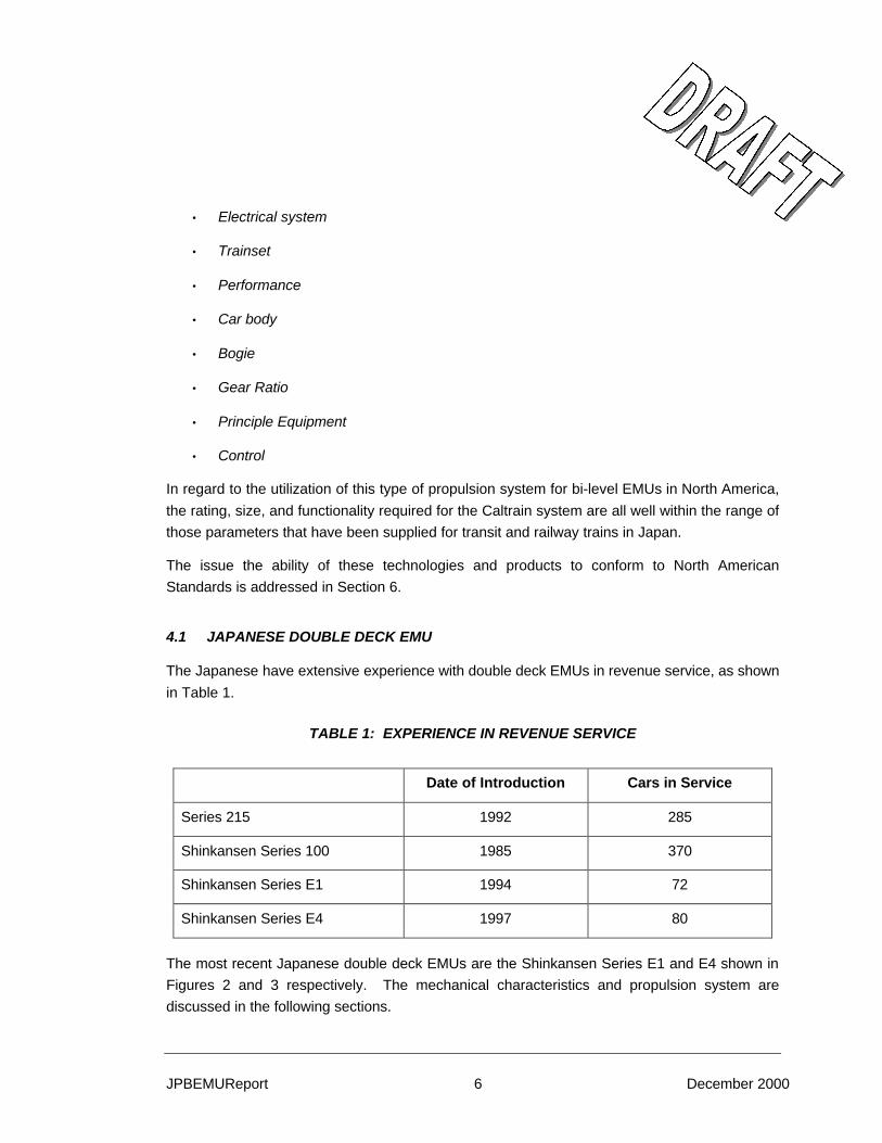
4.1 JAPANESE DOUBLE DECK EMU
The Japanese have extensive experience with double deck EMUs in revenue service, as shown
in Table 1.
TABLE 1: EXPERIENCE IN REVENUE SERVICE
Date of Introduction Cars in Service
Series 215 1992 285
Shinkansen Series 100 1985 370
Shinkansen Series E1 1994 72
Shinkansen Series E4 1997 80
The most recent Japanese double deck EMUs are the Shinkansen Series E1 and E4 shown in
Figures 2 and 3 respectively. The mechanical characteristics and propulsion system are
discussed in the following sections.

JPBEMUReport 7 December 2000
4.1.1 MECHANICAL CHARACTERISTICS
The mechanical characteristics of the Shinkansen Series E1 and E4 bi-level electric multiple
unit cars are almost identical, with a top speed of 240 kph (150 mph). The design of these cars
is governed by matching the structure gauge and the track quality standards that have been
established for Shinkansen cars. The rate of change of horizontal and vertical curves, minimum
vertical and horizontal radii, and levels of super elevation were all determined for the initial
series of cars. Consequently, the dynamic characteristics and bogie designs have been
constrained to conform to these characteristics. Japanese track characteristics are generally
better than typical railroad track quality in North America. Consequently, changes in the design
of the cars would be needed to accommodate the North American track quality standards.
Japanese National Railways has been divided into six different companies. The East, Central,
and West Japan Railway companies have adopted a design operating philosophy that there will
be no crashes. As a result of this they have not incorporated the energy absorption
characteristics that are required by the new FRA Standard CFR 238-403. For this reason we
have concentrated our evaluation on the merits of the electrical characteristics of these cars, as
these are more readily transferable to the North American railway environment.
East Japan Railways Series E4 represents the most modern evolution of the propulsion system
design. It has been proven by two years of revenue service.
4.1.2 PROPULSION SYSTEM
The East Japan Railway has designed a propulsion system that has 50 percent of all axles
powered. As shown in Table 2, Series E4 Car Configuration, the four-motored cars of the total
of eight cars have traction power driving the axles.

JPBEMUReport 8 December 2000
TABLE 2: SERIES E4 CAR CONFIGURATION
Car No. 1 2 3 4 5 6 7 8 Item Tc1 M1 M2 T T Mp Mc Tc
Cab 3 3
Pantograph 1 1 Transformer 1 1 Converter 2 2 2 2 Inverter 2 2 2 2 Traction Motors 4 4 4 4 Auxiliary Inverter 1 1
The transformer, converter and inverter change the 25 kV, 50 Hz power supply from the
overhead catenary to a VVVF supply. This VVVF is the power source for the induction motors,
which have a rated condition of 1850 Vac at 130 Hz. The converter transforms the 25 kV, 50
Hz signal into a fixed dc voltage.
The converter is a fully controlled bridge using IGBTs. This provides an additional element of
control allowing the system to respond to fluctuation in the supply voltage. This also provides
more options in the control strategy for maximizing the electromagnetic compatibility of the
propulsion system with other subsystems in the car and ground facilities.
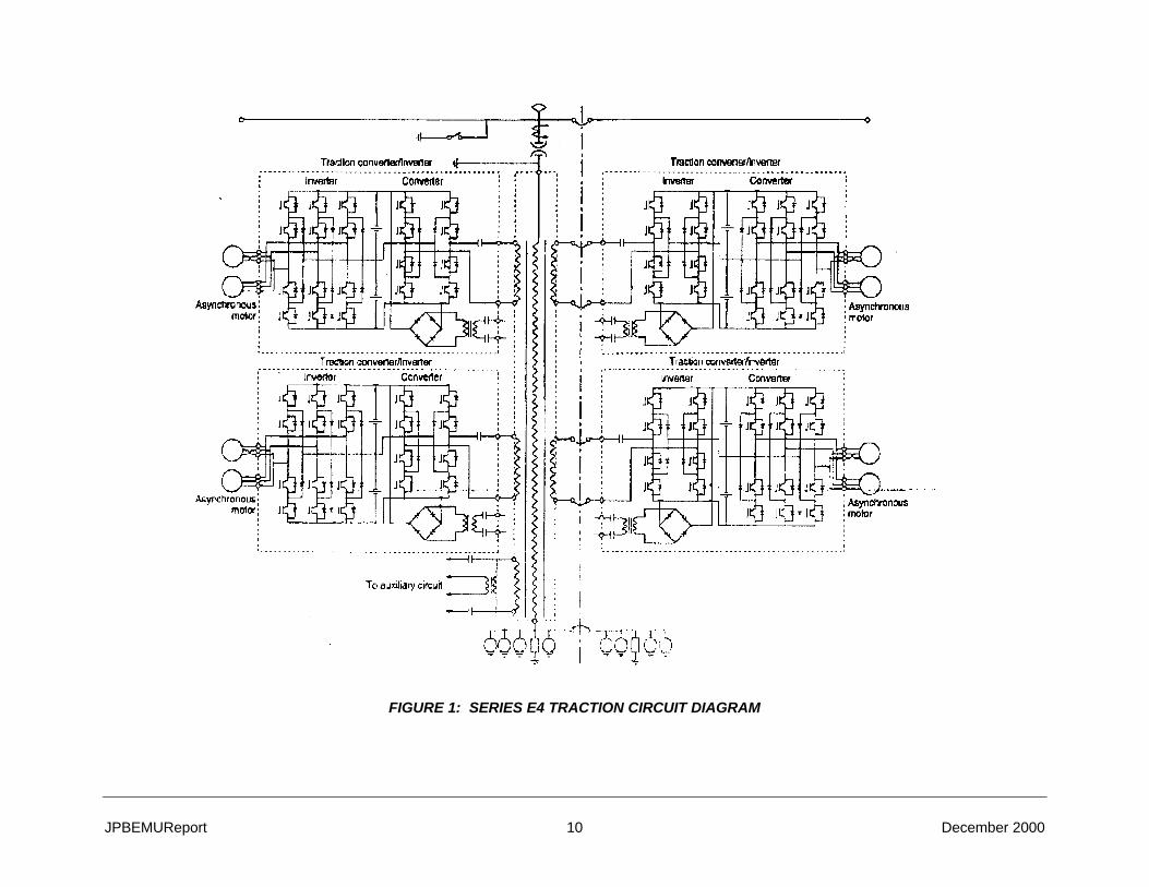
Figure 1 shows the schematic for the traction and propulsion system for a pair of motorcars.
One transformer supplies the power for the propulsion system on a pair of motorcars. As
shown in Table 1, each motorcar has two converters and two inverters. Each inverter provides
the power of a VVVF nature to the induction motors that drive the two axles of a single bogie.
The inverter and converter are packaged into one unit, providing more flexibility for the
mechanical designer in achieving weight balance on the car. The drive torque from the
induction motors is transmitted to the axles by a parallel Cardan drive with a gear coupling.
There are two auxiliary inverters installed in each 8-car train.
Further details of the major propulsion system components are discussed in Appendix B, where
a tabular comparison of four Japanese propulsion systems is also presented:
• Supply • Protection
• Inverter • Traction Motor
• Drive Method • Braking System
• Control System
JPBEMUReport 10 December 2000
FIGURE 1: SERIES E4 TRACTION CIRCUIT DIAGRAM

JPBEMUReport 11 December 2000
4.1.3 TRACTION TRANSFORMER
Traction transformers are mounted on the floor. The main converters controlling the traction
motors are installed in the left and right side machine rooms provided on both sides of the
center aisle in the rear vestibule of all M cars. The converter and inverter sections for the two
main converter sets are integrated together and housed in the same machine rooms. This is
advantageous because the wiring running along the center aisle can be omitted and the weight
of the right and left side machine rooms can be balanced. This integration makes the system
more compact and lightweight.
A single traction transformer provides the electrical power to the four main converters for two
cars. It consists of four secondary coils and one tertiary coil for an auxiliary circuit. A polyamide
film and an aluminum coil are used to insulate the element wires of the primary and secondary
coils, keeping them compact and lightweight. These features minimize total weight.
4.1.4 CONVERTER
The converter is a phase control, full wave bridge. As such, it is one element of a three-level
converter/inverter control system that reduces the higher harmonics of the primary current and
the ripple effect on motor current. The converter solved the problem of higher harmonics
affecting ground facilities, and greatly reduced the audible noise emitted from the traction
transformers and motors. An IGBT with a self-protective function increases the reliability of the
main circuit elements.
For cooling, two redundant fan sets are used for the converter.
4.1.5 INVERTERS
The inverters change the dc power produced by the converters to ac power. They produce a
VVVF output that provides the means to control both speed and traction torque efficiently. One
inverter provides power to two induction motors that drive the two axles of a truck.
Three sets of inverters are used to ensure optimum cooling and high availability for operation.
4.1.6 CONTROLS
The inverter is controlled by a 32-bit microprocessor based traction control unit. The traction
control unit has the following functions:
• Decoding the driving commands from the cab
• Acceleration / deceleration control

JPBEMUReport 12 December 2000
• Forward and reverse control
• Rollback protection
• Load compensation
• Jerk control
• Slip/slide control
• Controlling braking chopper for regenerative/rheostatic blended brake
• Interface with friction brake
Since a 32-bit Large Scale Integration (LSI) digitally controls the inverter frequency, there is no
temperature drift. The operating frequency of the LSI is 32 MHz.
The motor torque and speed are controlled by the Vector Field Control method. This achieves
smooth acceleration and enhances the ride quality for the passenger.
The Vector Field Control also achieves quick and precise control of motor torque when the
wheels slip in motoring or skid in dynamic braking. This slip/slide correction with the Vector
Field Control is applied to each inverter, which thereby corrects the spin or slide on the two
axles of a bogie. It maximizes the adhesion between wheels and rails to stabilize the train
acceleration and braking, and avoids the damage to wheels and rails in slipping or locked
wheels.
The logic control unit is provided with a fault logging function. A fault in the traction inverter
system triggers fault data logging. The fault annunciation and the detailed logged data are
transmitted to a vehicle monitoring system.
4.1.7 TRACTION MOTOR
Insulated bearings, allowing operation of 900,000 km or more without an overhaul, are used in
the traction motor. They are compact in size, lightweight, and maintenance free. The design of
the bearing structure allows lubrication without requiring disassembly of the traction motor.

JPBEMUReport 13 December 2000
TABLE 3: SUPPLY RECORD OF PROPULSION INVERTER
No Country Transit Name Contact Name / Tel Performance Record Supply
Quantity
1. USA Northern Indiana Commuter Transportation District Mr. Daniel J. Gorstein +1 219 874 4221
Under the running test / manufacturing 54*
2. USA Port Authority of New York and New Jersey +1 212 435 7000 Under manufacture 64*
3. Canada British Columbia Rapid Transit Company Ltd. Mr. Christopher B. Morris +1 604 520 3641
Under manufacture 120*
TABLE 4: SUPPLY RECORD OF AC TRACTION MOTOR
No Country Transit Name Contact Name / Tel Performance Record Supply Quantity
1. USA Northern Indiana Commuter Transportation District Mr. Daniel J. Gorstein +1 219 874 4221 Testing 8
TABLE 5: EVIDENCE OF AUXILIARY ELECTRIC SYSTEM IN-SERVICE PERFORMANCE
Item Transit Name Contact Name / Tel Car Series System Voltage
No. of Units (GTO)
No. of Units (IGBT)
Year of Supply Performance Record
1. Chicago Transit Authority Mr. Walter R. Keevil +1 312 664 7200
EMU DC 600V 1 1996 Approx. 100,000 miles
2. Metro North +1 212 340 3000 Subway Car DC800V, AC13800V
70 1 1996 Approx. 200,000 miles
3. New York City Transit Authority
Mr. Leonard Chimelewski +1 718 694 4506
Subway Car DC 600V 346 1999 -* Under manufacture and testing
4. New York City Transit Authority
+1 718 330 3000 Subway Car DC 600V 638 1985 Approx. 800,000 miles
5. Northern Indiana Commuter Transportation District
Mr. D. Gorstein +1 219 874 4221 EMU DC 1500V 14
2000-2001* Under manufacture
Total 708 362
Remarks: * = Under Manufacture

JPBEMUReport 14
4.2 JAPANESE EMU SUPPLIERS
There are a total of four Japanese rolling stock companies currently manufacturing bi-level or
Gallery style EMUs.
• Kawasaki Heavy Industries
• Kinki Sharyo
• Nippon Sharyo
• Tokyu Car Corporation
In addition, four companies are currently manufacturing electric propulsion systems for bi-level
EMUs.
• Hitachi Limited
• Mitsubishi Electric Corporation
• Toshiba Corporation
• Toyo Denki
With many manufacturers capable of producing equivalent products, North American authorities
can be assured of receiving competitive bids from a number of suppliers. Appendix D provides
some background on each of the above suppliers.
5 EUROPEAN TECHNOLOGIES
European countries have embraced both the electrification of railways and the adoption of multi-
level passenger rail cars almost unanimously. Trains comprising passenger cars hauled by
electric locomotives or electric multiple units, are common approaches to solve transportation
problems in most major cities.
Rolling stock and equipment suppliers have responded aggressively to the demand for new,
modern and safe technologies.
The approach to the development of new technology for subsystems and trains in Europe is
quite different from that in the U.S. Here technology is often developed on a competitive basis
and is owned by the manufacturers. In Europe the technologies are developed for national
railways and to suit particular national requirements and environment. It occurs on a
cooperative basis between the transit operators and the train manufacturers. The ownership of
the design resides usually with the particular manufacturer. Thus, the design and certainly the
JPBEMUReport 15
manufacturing rights are proprietary and when a particular design is reproduced by a different
manufacturer, such as the case with the Gallery cars, the new contractor must undertake new
engineering work.
This approach precludes the railways from having a number of manufacturers that are able to
compete for contract awards for commercial supply of the car designs. To large extent, this was
not an issue as the manufacturers were selected to support the national interest in having a
viable manufacturing industry. There are now, however, trends within the European Community
to completely open the award of contracts to competition among the European manufacturers
and to discourage national purchasing preferences.
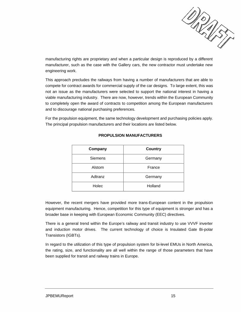
For the propulsion equipment, the same technology development and purchasing policies apply.
The principal propulsion manufacturers and their locations are listed below.
PROPULSION MANUFACTURERS
Company Country
Siemens Germany
Alstom France
Adtranz Germany
Holec Holland
However, the recent mergers have provided more trans-European content in the propulsion
equipment manufacturing. Hence, competition for this type of equipment is stronger and has a
broader base in keeping with European Economic Community (EEC) directives.
There is a general trend within the Europe’s railway and transit industry to use VVVF inverter
and induction motor drives. The current technology of choice is Insulated Gate Bi-polar
Transistors (IGBTs).
In regard to the utilization of this type of propulsion system for bi-level EMUs in North America,
the rating, size, and functionality are all well within the range of those parameters that have
been supplied for transit and railway trains in Europe.

JPBEMUReport 16
5.1 EUROPEAN BI-LEVEL EMUS
The Europeans have significant experience with EMUs in revenue service. A few examples are
shown below.
EXPERIENCE IN REVENUE SERVICE
Model Country Date of
Introduction Cars in Service
M12N France 1992 210
TER 2N France 1995 152
BR 445 Germany
1996 1 preseries 3-car
trainset
TAF Italy 2000
In November 2000, it was announced that a consortium comprised of Bombardier
Transportation and Alstom Transport has received a firm order from the French National
Railways, Societé Nationale des Chemins de fer Français (SNCF) for 72 TER 2N NG (New
Generation) electric multiple unit trainsets. The contract has options for an additional 426
vehicles. First deliveries are scheduled to begin December 2003.
5.1.1 MECHANICAL CHARACTERISTICS
The mechanical characteristics of these European bi-level cars are driven by the commuter rail
application. The trains will operate at speeds of 90 mph. on lines generally dedicated to
passenger traffic. This dedicated operation permits the maintenance of high track standards.
Consequently, changes in the design of the suspension systems would be needed to
accommodate the North American track quality standards.
The EEC directives require the incorporation of energy absorving design features. The railways,
in cooperation with the manufacturers, have undertaken an ambitious program, including
simulations and actual tests, to understand the dynamics of accidents. The results will be
incorporated on standards that will apply to new rolling stock equipment. It is important to note
that the outcome is not expected to create significant changes on the general philosophies, but
will likely allow to produce better and safer vehicle designs. The requirements are different from
those of the new FRA Rules, CFR 49, Part 238-403, which is governed by the mixed passenger
and freight usage.
JPBEMUReport 17
5.1.2 PROPULSION SYSTEM
The overhead catenary has a variety of supply conditions:
• 1,500 Vdc
• 15 kV, 16 2/3 Hz ac
• 25 kV, 50 Hz ac
• 50 kV, 50 Hz ac
This VVVF is the power source for the induction motors. The converter transforms the 25 kV,
50 Hz signal into a fixed dc voltage.
The converter is a fully controlled bridge using IGBTs. This provides an additional element of
control allowing the system to respond to fluctuation in the supply voltage. This also provides
more options in the control strategy for maximizing the electromagnetic compatibility of the
propulsion system with other subsystems in the car and ground facilities.
5.1.3 INTERIOR ARRANGEMENTS, PASSENGER COMFORT AND AMENITIES
The European cars described in this report offer modern and attractive interiors and boarding
accessibility. All cars evaluated for instance, have two large 50” to 52” wide doors per side and
boarding is at the low floor, in the range of 25 to 27” from top of rail; the 2+2 seating, allowing
for clear and safe aisleways; accommodations for the handicapped; large windows and
excellent lighting. These features offer safe and comfortable access to the on-board facilities
and amenities. With regard to the height of the low floor of the car, it is technically feasible to
bring it down to 17” from top of rail, improving the access to the car in a safe manner, and
helping to reduce dwell times at stations.
Following is a more detailed description of the most relevant bi-level EMUs:
5.2 TER 2N
This is the newest order for 72 bilevel EMU trainsets in Europe, placed by SNCF in France in
November, 2000. The price of the initial order is 420 million Euros (US$ 385.5 million or US$
5.345 million per unit or married-pair) and SNCF would award an option for additional 426
vehicles. These prices should not be compared to those encountered in the U.S. market, since
there are usually a variety of other conditions, such as warranties, spare parts and contractual
terms and conditions, affecting the price of each car.
The cars are being built by a joint venture formed by Bombardier and Alstom.

JPBEMUReport 18
This is the fourth generation of electric traction equipment for bilevel vehicles for SNCF. It has
been developed for regional transportation (local or express trains) for distances ranging from
100 to 200 km. It features a modular design, which allows the formation of trainsets of 2 to 5
units, while maintaining traction/braking performance. Each unit is a married pair of 2 cars.
Passenger capacity according to SNCF’s seating arrangement specifications is 210 for a single
married pair, including 19 in first class, 175 in second class and 16 on flip-up seats. The total
capacity is 388, including seated and standing passengers.
A similar model called the MI 2N is more specifically adapted to higher capacity requirements
for services around Paris. Each train consist is formed by 5 cars and each car has 3 doors per
side, for greater and faster flow of passengers.
Following a typical arrangement for SNCF, the propulsion equipment is installed in one of the
married pairs, while the second is a trailer. Both cars are equipped with control cabs. Each car
has two 51.2” wide doors per side. The entrance is at approximately 28 to 30” above top of rail
(TOR). Only the trailer is equipped with accommodations for the handicapped, including a toilet
and seating space.
Each Married Pair is 172’ long, 14’ high and 9.2’ wide. The total weight for the Married Pair is
274,000 lbs.; the power car weight is 159,000 lbs. and the trailer 115,000 lbs.
The electrical equipment is designed to work under systems supplying 1500 Vdc and 25 kV, 50
Hz ac. There is also the possibility of working under 3000 Vdc or 15 Kv 16 2/3Hz ac. Maximum
speed is 90 mph, the acceleration rate is 0.9m/s2 and the brake rate is also 0.9 m/s2.
5.3 TRENO AD ALTA FREQUENTAZIONE (TAF) EMU
TrenItalia, the operating company created in June 2000 by the Italian State Railways, is also
procuring a fleet of 104 modern bilevel EMUs. The Italian contractors Ansaldo-Breda and
Firema are supplying the trains. Adtranz supplies the electrical equipment. The first of these
trains was introduced two years ago in commuter service in Rome.
A typical train consist is formed by four cars, including a power car, two trailers and a power car.
Both power cars are equipped with control cabs at one end. Overall dimensions are:
Ø Length: 85’
Ø Width: 9.2’
Ø Height: 14.1’

JPBEMUReport 19
Ø Weight: 136,400 lbs.
With clearances more restrictive than in the United States, the side walls/windows at the upper
level taper-in quickly, reducing the interior space.
The four car consist has total passenger capacity of 841, with 469 seated and 372 standing.
The seating arrangement is typically European, of 2+2, face-to-face. Each car has two large 70”
wide bi-parting entrance doors per side, at 25.5 inches from top-of-rail. Each power car is
equipped with one toilet room and each trailer car is equipped with one accessible toilet.
The interior of the car is very attractive, offering modern amenities and passenger comfort.
The vehicles are designed to operate at a maximum speed of 90 mph at an operating voltage
range of 2000 to 4000 Vcc. The peak traction effort is 214 kN and the continuous traction effort
is 147 kN. One truck per power car is equipped with traction motors, all other trucks are
unpowered.
The static power system uses GTO impressed voltage inverters to feed the traction motors (two
per truck). The traction drive semiconductors are cooled by a water based system which is
environmentally friendly. The microprocessor control system provides redundant common
vehicle functions and provides support for resident diagnostics. The low voltage command and
control circuits are fed at the nominal battery voltage of 24V. A low voltage trainline provides
power car battery charger redundancy.
The brake system incorporates regenerative, rheostatic, electro-dynamic braking and automatic
electro-pneumatic braking.
5.4 SIEMENS
Siemens has extensive experience in the development and supply of electric traction equipment
and power conditioning systems throughout the world. Siemens has not built an integrated bi-
level EMU, however it has built non-powered bi-level cars for commuter services in the city of
Vienna, Austria, as well as numerous single-level EMU’s. Siemens has assembly plants in the
United States (Sacramento, Long Beach, Ca.) and has delivered several orders of electrically
propelled LRV and Metro type cars. Siemens is therefore, very familiar with FRA Rules and
Regulations and related Recommended Industry Practices.
Siemens also has extensive experience in turn-key type projects, including vehicles,
maintenance services and power supply and distribution systems. Siemens should be
considered a serious competitor in the PCJPB Electrification project.

JPBEMUReport 20
5.5 ADTRANZ
In cooperation with Alusuisse of Switzerland, Adtranz built the IC2000 bi-level electrically
powered trains for use in commuter and intercity passenger services in Switzerland. The trains
are typically formed by power and trailer cars, with the power equipment installed at one end of
the car, over the trucks and immediately behind the control cab.
As with Siemens, Adtranz has extensive experience in the development and supply of electric
propulsion and traction equipment for both locomotives and passenger cars. Adtranz also
supplies rolling stock equipment and provide maintenance services. Adtranz has facilities in the
U.S. and should be considered a serious competitor.
6 U.S. TECHNOLOGY
The only multi-level EMU ever built in the United States was the Gallery style car for the Illinois
Central Gulf Railroad (ICG), whose commuter passenger rail services are now under the control
of METRA. The first order was built by St. Louis Car in 1972 and the second by Bombardier in
1979, utilizing the same design. Both contractors built a total of 165 cars. The cars operate on
1500 Vdc supplied by overhead wires and the power control is through a motor driven cam. All
cars and all axles are powered.
Given the latest developments in electronics and related systems, the propulsion technology
used in the mid-to-late seventies can be considered obsolete.
There are however several transit authorities utilizing single level EMUs, where more modern
technologies are being applied. The more recent procurements include the Bombardier M-7
cars for the Long Island Railroad, currently under construction; the Nippon-Sharyo cars built for
the Northern Indiana Transportation District (NICTD), the Morrison-Knudsen M-6 cars for Metro
North, and the Bombardier built Deux-Montagne cars for Montreal, among others. In addition,
modern propulsion and traction technologies were also applied to cars remanufactured by
Adtranz for New Jersey Transit.
In any case, it is important to note that all propulsion technology being employed in the U.S.
market is of foreign origin. Mitsubishi for instance, is supplying the electrical equipment to
Bombardier for the Long Island cars and Toshiba is supplying the equipment to Nippon-Sharyo.
Other suppliers of electrical equipment in the United States are Alstom, Adtranz and Siemens,
among the most active in the market.

JPBEMUReport 21
6.1 M-7 LONG ISLAND RAILROAD CARS
Following is a description of the single level EMUs being constructed by Bombardier for the
Long Island Railroad.
6.1.1 TRAIN DESCRIPTION
The train cars are configured for normal operation as two-car units (married pairs). Each
married pair consists of two cars of different types, designated A Cars and B Cars. Train
consist length under normal operating conditions can include as many as 14 cars and may be
operated in consists up to 28 cars in length, but at reduced speed and performance.
The LIRR M-7 car propulsion system provides the performance required under all conditions on
the electrified portions of the present Long Island Railroad and future service to Grand Central
Terminal (GCT) and the Hudson and Harlem Lines of the Metro-North Railroad.
The cars are to provide commuter service up to 80 mph. In addition, each car is capable of
operating in commuter service at sustained speeds of up to 100 mph.
6.1.2 CAR PROPULSION SYSTEM CONFIGURATION
The A and B cars each have four powered axles. There are two independent inverters on each
car.
The propulsion system truck mounted products consist of the following:
Ø Traction Motors with speed sensor
Ø Gear Unit with ground brush
The carbody-mounted products consist of the following:
Ø Inverter Box
Ø Circuit Protection Box
Ø Brake Resistor

JPBEMUReport 22
A schematic representation of two truck sets of propulsion equipment is shown in Figure 1.
FIGURE 2: CAR PROPULSION SYSTEM EQUIPMENT
The major propulsion system components are described in the following sections.
6.1.3 INVERTER
Each inverter controls and powers two motors on a truck and has a separate and independent
propulsion controller. The inverter power section consists of IGBTs. The inverter is
characterized by the following ratings.
650 Vdc
Inverter #2
Circuit Protection Box
BrakeResistor
Inverter #1
TractionMotors
GearUnits
Carbody Mounted Truck Mounted

JPBEMUReport 23
Input: 650 Vdc
Output Voltage: Variable 0 to 480 Vac, 3-phase, line voltage
Output Current: 320 amps
Rated Frequency: 70 Hz
Load: Traction Motors, two parallel connected, each approximately 260 hp(shaft)
Each inverter equipment box includes the following items of equipment:
• Inverter Module
• Line Contactor
• Charging Contactor
• Filter Inductor
• Filter Capacitor
• Propulsion Controller
.
6.1.4 PROPULSION CONTROLLER
The Propulsion Controller provides the logic and control functions required to operate the
inverter. It transforms the trainline signals for accelerating, cruising, coasting and braking
modes from the Master Controller to the necessary frequency and voltage output from the
inverter.
The Propulsion Controller is the repository for the fault and operational data collected by and for
the propulsion system. It also interfaces with the Central Diagnostic System and the Portable
Interface Unit to provide operational, fault and maintenance information to the train or
operations or maintenance staff.
6.1.5 TRACTION MOTOR
Each car will be electrically propelled by alternating current (ac) propulsion technology. The
motors are three-phase, ac induction motors with squirrel cage rotors. They are powered by a
variable-voltage, variable-frequency (VVVF) supply that is created by the inverter from the
650 Vdc third rail supply. By means of the VVVF supply, the torque and speed of the traction
motors are independently controllable for all operation conditions of input voltage, car loading
and gradients.

JPBEMUReport 24
The configuration is one traction motor per axle, and one inverter and an associated Propulsion
Controller for each truck.
Table 6 - LIRR ac traction motor ratings and characteristics.
Type 3 phase squirrel cage rotor induction motor, self-ventilated
4 poles
Rating Category Continuous
Output 260 hp (approx.)
Voltage 480 V
Current 320 A
Max Revolution Approx. 6500 r/min
Frequency 70 Hz
Insulation class Class 200
6.1.6 GEAR UNIT
The gear unit that transmits the tractive effort from the motor to the axle of the car is a parallel,
single reduction type with helical type gears.
The Gear unit also comprises a flexible coupling that connects the gearbox to the output shaft of
the traction motor. This is a double, internal and external, self-aligning type of coupling.
6.1.7 CIRCUIT PROTECTION BOX
The purpose of the Circuit Protection Box is to connect and isolate the propulsion system from
the third rail supply and to monitor the current drawn and voltage supplied. The Circuit
Protection Box includes a High Speed Circuit Breaker.
6.1.8 BRAKE RESISTOR
Electric braking is provided in which power generated by traction motors, when configured as
generators, is dissipated as heat by dynamic brake resistor grids and/or is supplied to power the
auxiliary loads on the train.

JPBEMUReport 25
6.1.9 PASSENGER ACCOMODATIONS AND AMENITIES
The M-7 car is a high capacity single level car, accommodating 93 seated passengers on the
typical 2+3 Northeast seating arrangement and there are two wheelchair locations. The cars
have two 50” sliding doors per side with boarding from high level platforms. No steps are
required. Half of the fleet (113 cars) is equipped with toilets accessible to the handicapped.
No dedicated space for bicycles is provided.
The customer and the contractor claim that the interior of the car was designed with input from
passengers and employees, and offer cellular phone connections and other amenities.
The fabricated trucks and coil/pneumatic suspension system is designed to provide high quality
ride to the passengers.
6.2 NICTD PROPULSION SYSTEM
The new NICTD car propulsion system incorporates state-of-the-art technology in its major
systems components, which consist of four traction motors, four gear units, one inverter, one
input circuit protection and one brake resistor box. The propulsion system configuration is
shown in Figure 4. The minimum train formation is 3M1T (M-M-T-M).
The inverter utilizes a configuration of IGBT power semiconductors to achieve a variable-
voltage variable-frequency output. The precise control over the motoring and braking thrust is
achieved using the vector control method to generate a pattern of IGBT gate signals in
response to a thrust command signal. Vector control is an algorithm that controls the motor
torque by the independent control of two derived or equivalent currents, namely the torque
current component and the magnetic flux current component.
The vector control is part of the propulsion controller that provides the logic and control
functions required to operate the inverter. The propulsion controller also translates the trainline
signals for accelerating, cruising, coasting and braking modes from the Master Controller to
request the necessary frequency and voltage output from the inverter.
The cars are propelled by alternating current (ac) technology. The traction motors are three-
phase, ac induction motors with squirrel cage rotors. Utilization of high temperature insulation,
quality magnetic materials and optimal design techniques result in low weights and volumes for
the traction motors.
The single reduction gear unit includes a flexible coupling that connects the gearbox to the
output shaft of the traction motor

JPBEMUReport 26
Input circuit protection and isolation is accomplished with a high-speed circuit breaker.
Monitoring of the current drawn and the supply voltage is also provided.
General characteristics of the propulsion system are presented in Table 1.
TABLE 6: NICTD PROPULSION SYSTEM GENERAL CHARACTERISTICS
1. Inverter VVVF with vector field control, IGBT, 1100 kVA, 0 to 1100 V, 0 to 130 Hz, natural convection cooling
2. Traction Motor Three-phase, squirrel cage induction motor, 150 kW, 1100 V, 102 A, 1755 rpm, 4 poles
3. Motor speed, maximum safe Typically 6000 rpm
4. Motor cooling Forced air
5. Dynamic brake resistor design Edge wound, ribbon steel element
6. Resistor cooling type Natural convection
7. Gear Box Single reduction gear, approx. 4:1

JPBEMUReport 27 January 2001
FIGURE 4: NICTD PROPULSION SYSTEM EQUIPMENT
With regard to passenger accommodations and amenities, this single level, stainless steel car
offers the typical U.S. commuter vehicle arrangement, as follows: two 36” entrance doors per
side at the end vestibules, with steps for boarding from low level platform; 2+3 seating
arrangements to accommodate 94 seated passengers and 2 wheelchairs. There is no space
allocated for bicycles.
1500 VdcCircuit Protection Box
BrakeResistor
InverterTractionMotors
GearUnits
Carbody Mounted Truck Mounted

JPBEMUReport 28 January 2001
7 U.S MANDATORY REQUIREMENTS AND INDUSTRY STANDARDS
On May 12, 1999, the Federal Railroad Administration (FRA) issued comprehensive Rules
addressing the design, construction and maintenance of rail passenger cars, CFR 49 Parts 238
and 239. Tier I of the Rules apply to “…railroad passenger equipment operating at speeds not
exceeding 125 mph…”. Further, the Rules establish the effectivity of the requirements as
follows: “Unless otherwise specified, these requirements only apply to passenger equipment
ordered on or after September 8, 2000 or placed in service for the first time on or after
September 9, 2002.
The Rule also states that: “The structural standards of this subpart…do not apply to passenger
equipment if used exclusively on a rail line:
(i) with no public highway-rail grade crossings;
(ii) on which no freight operations occur at any time;
(iii) on which only passenger equipment of compatible design is utilized;
(iv) on which trains operate at speeds not exceeding 79 mph.
The Rule provides for alternative compliance by demonstrating “…at least an equivalent of
safety in such environment with respect to the protection of its occupants from serious injury in
the case of a derailment or collision”
Given the likelihood that JPB’s equipment:
a) will or could operate in the future on the same lines as other freight and passenger
trains; and…
b) that it will likely operate at speeds higher that 79 mph in the foreseeable future,
it is therefore reasonable to assume that any new rolling stock equipment, electrically powered
or not, will be subject to the FRA Rules, Part 238, as currently written. The likelihood of
obtaining any waivers or offering alternative solutions is very low.
In addition to mandatory requirements (FRA Rules and Regulations) the commuter rail industry
is also guided by Recommended Industry Standards and Practices developed by the American
Public Transportation Association (APTA) under full participation and consensus of commuter
rail operators and agencies. These Recommendations are a modern version of the old
Association of American Railroads (AAR) Recommended Practices for the design and
construction of rail passenger cars. The Recommendations are consistent with the FRA Rules
and although do not have the mandatory force of the Rules, commuter rail operators are
committed to comply with

JPBEMUReport 29 December 2000
With regard to electrical equipment, more specifically propulsion inverters, traction motors, and
auxiliary electric systems of European and Japanese origin, state-of-the-art technologies have
already been implemented in the U.S., adapted to meet all industry practices and standards.
Appendix C provides further detail on the typical requirements and standards that would have to
be met by a propulsion system. The following requirements have been addressed:
• Noise, Vibration, Ride Quality
• Electromagnetic Interference and Compatibility
• Reliability
• System Safety Program
• AC Power Supply
• Low Voltage Power System
• Equipment Ventilation
• System Components
• Component Qualification Tests
• System Conformance Tests
Typical standards associated with the requirements are also included in Appendix C.
Foreign manufacturers have experience with IEEE and NEMA motor standards. Also many IEC
standards are used in NA for the detailed specification of traction equipment. As a result only
minor changes in design would be required to meet U.S. requirements.
The electromagnetic compatibility issues expressed in the U.S. Standards are more specific to
our operating environment and practices, therefore some equipment design changes would be
required.
Only minor design changes would be required for the converter/inverter equipment. Most of
those would be associated with the input supply voltage and frequency, and the inverter output
voltage and frequency.
All standards requirements are manageable and achievable through the design process.

JPBEMUReport 30 December 2000
8 CONCLUSIONS AND RECOMMENDATIONS
With the development of electrical and electronic technologies, propulsion and traction
equipment in Europe and Japan have made a dramatic advance over the past 5 to 7 years.
These developments have resulted in more reliable and powerful packages, easier to maintain
and to operate. It also has allowed assembling the equipment in a more efficient package,
especially when applied to bi-level passenger rail cars.
Both European and Japanese electrical propulsion technologies can be easily adapted to the
particular demands and requirements of the North American railroad environment.
With regard to the mechanical components of the car, especially car body structures and size, it
will need to be adapted or designed in compliance with the Rules and Regulations currently in
effect in the United States. While the PCJPB will be able to learn from a variety of modern
interior arrangements and amenities, door location and size and floor and stairway layouts, and
adopt the layout most suitable to the specific levels of safety and comfort to the passengers, the
final design of the vehicle must be in compliance with mandatory rules and regulations in force
in the United States. As discussed before, it is highly unlikely that foreign car body designs will
be allowed to operate as is.
With specific regard to the electrical characteristics of the double deck EMU units that are in
revenue service in Japan, the Japan Railway Companies have standardized on the use of a
VVVF inverter system with an induction motor drive as a means of achieving high levels of
torque and low weight. In addition, the VVVF system gives them the advantage of lower
maintenance costs over the life of the car.
The characteristics of supply and power levels mentioned in the particular example of the Series
E4 Shinkansen are different and much larger respectively than would be needed for this
particular application in California. Nevertheless, it is stressed that the technology is both
transferable and scalable. Therefore the characteristics found in the inverter induction motor
system for Shinkansens are readily applicable to EMUs and subway cars. The front end
section, whether it is a transformer/rectifier or converter, will have to be selected on the basis of
the type of power supply that is available. Since it is anticipated that the power will be 25 kV 60
Hz ac, the existing propulsion equipment for the E4 and similar Shinkansens can be readily
adapted to the particular requirements for the US bi-level EMU.
The propulsion and auxiliary power systems used by the various Japan railway companies
represent the state of the art with proven revenue service.
With regard to European technologies for rail passenger services, the industry has made
significant progress over the last few years. Given the increasing demand, bi-level cars have

JPBEMUReport 31 December 2000
now been adopted in most European countries, and because of the fact that most of those
railroads are electrified, the rolling stock is powered by electricity. The arrangement of the
power equipment is typically found in one or two cars in the train consist, formed by one or more
trailer cars.
With regard to the location and power of the propulsion equipment and the formation of each
unit (consisting of one or more cars, powered or trailer), the modularity of the components, a
concept truly optimized by European and Japanese manufacturers, permits a variety of options.
The arrangement and size will depend on the physical characteristics of the infrastructure
(vertical and horizontal geometries), the number of stops along the route, the capacity of the
trains (length and trailing loads) and the trip time requirements (acceleration and deceleration
rates, maximum speed).
The strategic arrangement and size of the power equipment will also permit the formation of
different size consists, addressing peak and non-peak or regular/express services in an efficient
manner.
It is not prudent at this time to attempt to determine the type of unit and train formation most
appropriate for the Caltrain services. The power arrangement should be determined through
simulation of a variety of reasonable options, once all elements and requirements of the service
and the corresponding duty cycle of the equipment are properly and correctly defined. At this
time one can only assume that certain power arrangement would be better than the other,
based on the experience of the European and Japanese users. But this would be speculative
and non productive.
A critical part in reaching an intelligent solution is, for instance, energy consumption. Through
simulations one can adopt optimum acceleration and deceleration rates, consistent with the
geometries of the infrastructure, or perhaps delay the trip 2 or 3 minutes, and obtain significant
benefits on consumption of energy and cost.
Alstom, Siemens, Adtranz and Ansaldo-Breda have all developed state-of-the-art propulsion
and traction equipment. Bombardier and CAF, among others have ample experience in
integrating electrical equipment to mechanical components, including bi-level passenger cars.
In summary, both European and Japanese manufacturers are highly capable and qualified to
produce rolling stock equipment adapted to the U.S. technical and regulatory railroad
environment.
It is important however to express a cautionary note at this time. If the decision is made to adopt
EMU rolling stock for the Caltrain electrified system, the eventual bi-level EMU suitable for the
services will likely be a new vehicle, formed by certain major existing components described in
this report. Under this scenario, the process of integrating all major systems and components

JPBEMUReport 32 December 2000
will be a critical aspect of the project. The ultimate long-term performance of the vehicles will
depend heavily on how well this process is approached and managed.
Unfortunately, history is not on our side in the United States. The most recent example of
attempting to match certain foreign rolling stock technologies with the U.S. rail infrastructure,
namely the Acela high-speed trains for the Amtrak Northeast Corridor service, is finding severe
difficulties. Ultimately, there is no doubt that most if not all technical problems will be solved, as
demonstrated by European and Japanese operators, but proper time for development, testing
and commissioning must be allowed. While European and Japanese manufacturers have
indeed demonstrated their capabilities in their own countries, it must be remembered that they
work closely with the railways during the development of specifications and development of the
vehicles. In the United States the environment is different, where a variety of technical and legal
factors contribute, right or wrong, to a more distant relationship between the customer and the
contractor.
It should also be remembered that carbuilders are good engineers but have little experience on
operations, and only recently are getting involved in maintenance contracts. The lack of solid
operating experience contributes to designs that do not perform as efficiently during revenue
services. The best approach to address these problems is to enter into a contractual
relationship that is truly a partnership. If one wins, the partner wins as well. If one looses, the
other one looses as well. This is not a common approach in the United States.
Procurement of the equipment is also a related issue affecting the results. European
manufacturers have gained experience in offering supply, maintenance and even operation of
the services in some cases. This procurement approach has advantages and disadvantages,
depending on the structure and mandate of the customer, labor issues, how the project is
funded and the strings attached to the funding.
Once those issues have been resolved and clarified, then the specification of the equipment can
be undertaken. This is extremely important because the scope of the procurement will drive the
type of specification to be prepared. For instance, if the procurement involves both supply and
maintenance of equipment, then the customer can enhance and enforce performance
guarantees by the contractor, including penalties and incentive payments. Under this scenario
the specification can and should be written by defining performance requirements only. If on the
other hand the scope of the procurement involves only the supply of the equipment and it is
limited to a low-bid process, then the specification should define design issues with more clarity.
As discussed before, procurement laws and policies affecting the PCJPB would drive the
process.

JPBEMUReport 33 December 2000
Based on the technical evaluation of locomotives and EMU type rolling stock equipment, the
decision to use either should be based on financial considerations and economic results. The
economic decision should be based on life cycle cost analysis, determining the overall initial
and operating cost of the equipment over the life of it. However, while this may be the most
appropriate approach, the available data or assumptions may not permit an accurate
assessment and determination. This is due to the availability of true maintenance and operating
costs reflecting the conditions in the United States, therefore data from foreign sources will need
to be modified and mixed with local assumptions.
A more reasonable alternative is to prepare Performance Specifications and allow the bidders to
offer either locomotive hauled train sets or EMU’s. This process must be carefully laid out and
properly managed in order to ensure optimum selection.
With regard to car interior arrangements, amenities, colors and materials, the Europeans have
generally done a better job in addressing passenger needs and comfort.. We must therefore
learn from that experience and use it in the best interest of Caltrain users. This can be achieved
through the Performance Specification process, clearly establishing the performance
parameters. Other critical aspects of this process are as follows:
• clear definition of the evaluation process and selection criteria of the bids;
• clear definition of the terms and conditions of the contract;
• realistic development and testing schedules, to avoid false expectations and unreliable
services;
• serious consideration of vehicle prices, as affected by volume. For instance, METRA in
Chicago recently awarded a contract to Nippon-Sharyo for 300 Gallery style cars at a
price of $ 1,329 million average, each. The last purchase of 20 Gallery cars by PCJPB
resulted on a unit price of $ 1.6 million for trailers and $ 1,734 million each for a cab car.
RVB+A
January 2001

JPBEMUReport 34 December 2000
APPENDIX A: COMPARISON OF JAPANESE DOUBLE DECK CAR EMUS
Model Double Deck
Electric Railcar Series 215
Shinkansen EMU Series 100
Shinkansen Double Deck EMU Series
E1
Shinkansen Double Deck EMU Series
E4 Electric System 1.5 kVdc 25 kVac, 60 Hz 25 kVac 50 Hz
Consist 12 motored cars and 4 trailers
4 motored cars and 6 trailers
6 motored cars and 6 trailers
4 motored cars and 4 trailers
Seating capacity 1319 1010 1235 819
Train set
Tare Weight (tons) 851 368.5 692.5 428 Maximum service speed 230 km/h
142.9 mi/h 120 km/h 74.5 mi/h
240 km/h 150 mi/h
Acceleration at starting 1.6 km/h/s 1.6 km/h/s 1.65 km/h/s
Performance
Rated traction motor output
185 kW 410 kW 420 kW
Structure Steel, with under floor suspended
equipment
Stainless steel, except for leading
car and part of under frame
Steel with airtight design
Aluminum alloy
Length (mm) M – 25,800 T – 24,500
M - 20,000 T - 20,500
M -26,050 T -25,000
M - 25,700 T - 25,000
Width (mm) 3380 2,900 3430 3,380 Height with pantograph
raised (mm) 4070
Height with pantograph folded
M - 4,000 T - 4,490
3980 Car 1 & 12: 4485 Cars 2 – 11: 4493
4485
Car body
Distance between bogie centers (mm)
17,500 M - 14,000 T - 14,150
17,500
Structure Air suspension type 2-axle bogie with
gear coupling device
Bolster less
Rigid wheel base (mm) 2,500 2,100 2,500
Bogie
Wheel Diameter (mm) 910 860 910

JPBEMUReport 35 December 2000
Model Double Deck
Electric Railcar Series 215
Shinkansen EMU Series 100
Shinkansen Double Deck EMU Series
E1
Shinkansen Double Deck EMU Series
E4 Gear Ratio 16:83 = 1:5.19 27:65 = 1:2.41 69:19 = 3.63:1 94:26 = 3.62:1
Pantograph 6 pantographs with slightly movable
contact strips 3 pantographs when
a bus is installed between 2
pantographs
PS21 2 per consist
Main Transformer 2,510 kVA 6 sets per consist
Not Applicable 3,700 kVA 3 sets per consist
4,105 kVA 2 sets per consist
Main Rectifier Not Applicable Converter controls one inverter 6 per consist
Converter (Gifts) controls one inverter
4 per consist
Traction Motor 230 kW 3 per car
Series dc motor 3-phase asynchronous motor
410 kW
3-phase squirrel cage asynchronous motor, continuous
rating 420 kW, forced air ventilation
Power Source Phase controlled rectifier
Cam controller Inverter (controls 4 motors)
Inverter (Gifts)
Principle Equipment
Air Conditioner Semi-concentrated heat pump
2 units per car
2 units/car, 20,000 kcal/h, sheathed resistance heater
Roof mounted centralized air-
conditioning equipment 37,500
kcal/h x 2, heater 30 kW x2
Integrated air conditioner cooling
system: 37,500 kcal/h, heating
capacity: 30 kW

JPBEMUReport 36 December 2000
Model Double Deck
Electric Railcar Series 215
Shinkansen EMU Series 100
Shinkansen Double Deck EMU Series
E1
Shinkansen Double Deck EMU Series
E4 Powering Continuous phase
control by thrusters Series/parallel switching with
resistance
VVVF vector field control Parallel Card an drive system
Braking Electric command dynamic brake, eddy
current brake and disc brake
Electric command air brake with regenerative
braking, straight air reserve braking, holding braking,
preventative snow braking
Electric command airbrake with regenerative brake
Control
Auxiliary Power Supply System
Static inverter 3-phase, 440 V, 190 kVA static inverter
Static inverter 12 kVA: Type 1 - dc/constant voltage ac, 100V, 50 Hz Type 2 – unregulated ac 100 V, 50 Hz 3 units per consist
Static inverter 16 kVA Type 1 - dc/constant voltage ac, 100V, 50 Hz Type 2 – unregulated ac 100 V, 50 Hz 2 units per consist

JPBEMUReport 37 December 2000
APPENDIX B: COMPARISON OF JAPANESE ELECTRIC PROPULSION SYSTEMS
Model Double Deck
Electric Railcar Series 215
Shinkansen EMU Series 100
Shinkansen Double Deck EMU
Series E1
Shinkansen Double Deck EMU
Series E4 Propulsion System
Voltage 25 kV 1.5 V 25 kV Frequency 60 Hz Dc 50 Hz
Supply
Current Collector Configuration Pantograph Protection High Speed Circuit Breaker Vacuum Vacuum
Continuous Power Rating N/A Power Semiconductor Type Thruster N/A IGBT Traction Motors Per Inverter N/A 4 2
Inverter
# Of Inverters Per Car 1 2 Type MT61
Dc motor 3-phase squirrel cage asynchronous motor
Number of Poles 4 Output Continuous Power Rating 410 kW 420 kW Voltage (max) 1,500 V 1850 V Current (max) 166 A Frequency (max) N/A 130 Hz Cooling System Forced ventilation
Traction Motor
Traction Motors per Car 4 4 Description Parallel Cardan
drive with gear coupling
Parallel Cardan drive with flexible
gear coupling
Drive Method
Gear Ratio 1:2.41 1:5.19 1:3.63 1:3.62

JPBEMUReport 38 December 2000
Model Double Deck
Electric Railcar Series 215
Shinkansen EMU Series 100
Shinkansen Double Deck EMU
Series E1
Shinkansen Double Deck EMU
Series E4 Propulsion System
Braking System Description Electric command dynamic brake,
eddy current brake and disc brake
Electric command air brake with regenerative
braking, straight air reserve braking, holding braking,
preventative snow braking
Electric command airbrake with regenerative brake
Control System Type Continuous phase control by thyristor
Series parallel connection
rheostatic control, superposed field excitation control (with regenerative
braking and constant speed
control)
VVVF inverter system 3-step PWM control Vector field control

JPBEMUReport 39 December 2000
APPENDIX C: TYPICAL US REQUIREMENTS AND STANDARDS
Requirement Equipment Affected Standard Noise, Vibration, Ride Quality
Equipment Noise Prior to Installation on Vehicle Traction motors IEC 349-2 Vibration and Impact Loads All vehicle equipment IEC 61373
Electromagnetic Interference and Compatibility Radiated Emission Limits All vehicle equipment FTA-MA-06-0153-85-11, MIL-STD-
461A, and SAE Recommended Practice ARP 1393, 5/3/76
Conductive Emission Limits All vehicle equipment FTA-MA-06-0153-85-6, Method RT/CE02A
Inductive Emission Limits All vehicle equipment FTA-MA-06-0153-85-8, method RT/IEO1A
Reliability Reliability and Failure Analyses System hardware and software
design MIL-HDBK-217 or certified field
failure data System Safety Program
General All vehicle equipment MIL-STD-882C Applicability of MIL-STD-882C All vehicle equipment MIL-STD-882C
AC Power Supply General Requirements Inverters IEEE 11
AC power supplies IEEE P1476 Low Voltage Power System
General LVPS and battery IEEE P1476 Storage Battery
Emergency Battery Cut-Out Switch Battery Circuit NFPA 130 Chapter 5-3.9 Equipment Ventilation
Ventilation Blowers Equipment and traction motor ventilation blowers
IEEE 11
NEMA MG-12.06 IEEE 11 System Components

JPBEMUReport 40 December 2000
Requirement Equipment Affected Standard Traction Motors Traction Motor IEC 349-2
IEEE 11 ANSI/AFBMA
NFPA 130 Gear Drive Gear Units ANSI/AFBMA
Dynamic Brake Resistors Brake Resistors NFPA 130 Component Qualification Tests
Motors AC Traction Motors Traction Motor IEEE 11 & IEEE 112
IEC 349 AC Auxiliary Motors AC Auxiliary Motors IEC Publication 349 or IEEE
Standard 112 DC Auxiliary Motors DC Auxiliary Motors IEEE Standard 11 or IEC Publication
349 System Conformance Tests
Motors All Motors IEC Publication 349, IEEE Standard 11, or IEEE 112, NEMA MG 1-12.06

JPBEMUReport 41 December 2000
PASSENGER ACCOMMODATIONS IN THE DOUBLE DECK SHINKANSEN EMU E4
CAR TYPE Tc M1 M2 T 1. Mp Ms Tpsc M – motor car
T – trailer car
CAPACITY 817 passengers for 8 car consist; 1634 for 16 car consist
2ND floor 40 64 64 55 55 55 36 18
Flat 14 14 12
1st floor 35 55 55 55 55 55 55 25
Total 75 133 119 124 110 122 91 43
EMPTY WEIGHT 53.3 52.3 56.9 50.3 51.2 52.9 56.9 54.2 428 (t)
LENGTH (ft’ ins’’) 84’ 4’’ 82’ .25’’ 84’ 4’’
WIDTH 11’ 1’’
HEIGHT 14’ 8’’
CLASS 2 2 2 2 2 2 1 2
DOORS 4 4 4 4 4 4 4 4
FACILITIES T;
Vending m/c.
Ph Ph Vending m/c
Ph; WhC T Ph; WhC Wh C lift;
Wh C T T – toilet; Ph phone;
WhC wheel chair
EXT CAR INFO Car No.; Destination, train name; reserved seats
INT CAR INFO Car No.; Departure/arrival times; station stops; facilities info; announcements; news
ALL CARS ARE AIR-CONDITIONED

JPBEMUReport 42 December 2000
PASSENGER ACCOMMODATIONS IN THE DOUBLE DECK SHINKANSEN EMU E1
CAR TYPE Tc1 M1 M2 T1 T2 M1 M2 Tpk Tps M1s M2s Tc2
CAR NO. 1 2 3 4 5 6 7 8 9 10 11 12
CAPACITY 86 121 121 135 124 110 110 91 75 91 91 80
EMPTY WEIGHT 56.2 59.2 61.2 53.7 53.6 59.2 61.7 55.2 54.6 59.4 62 56.5
LENGTH 85’ 6’’ 82’ .25’’ 85’ 6’’
WIDTH 11’ 3’’
HEIGHT 14’ 9’’
CLASS 2 2 2 2 2 2 1&2 2 1&2 1&2 1&2 2
DOORS 4 4 4 4 4 4 4 4 4 4 4 4
FACILITIES T; Vending m/c Ph T: V
m/c T; Ph; Vending m/c
Res. T; Wh C
lift; Wh C-T
T; WhC V m/c T
EXT CAR INFO Car No.; Destination, train name; reserved seats
INT CAR INFO Car No.; Departure/arrival times; station stops; facilities info; announcements; news
All cars are air-conditioned
SEATING CAPACITY 1235 FOR A 12 CAR CONSIST

JPBEMUReport 43 December 2000
PASSENGER FACILITIES IN THE DOUBLE DECK EMU 215
CAR TYPE Mc1 M’1 T T’ T’ Ts T’s T M’ Mc
CAR NO. 1 2 3 4 5 6 7 8 9 10
CAPACITY 64 120 111 120 120 90 90 111 120 64
Empty weight 56.2 59.2 61.2 53.7 53.6 59.2 61.7 55.2 54.6 59.4
Length M cars 65’ 7’’; T cars 67’ 3’’
Width 9’ 6’’
Height 13’ 4’’
DOORS 4 4 4 4 4 4 4 4 4 4
FACILITIES Ph T T Ph T Ph
INT CAR INFO station stops; facilities info; announcements; emergency instructions
All cars are air-conditioned
Seating capacity 1010 for a 10 car consist; 1522 for a 15 car consist

JPBEMUReport 44 December 2000
APPENDIX D: PHOTOGRAPHS
FIGURE 3: SHINKANSEN DOUBLE DECK SERIES E1

JPBEMUReport 45 December 2000
FIGURE 4: SHINKANSEN DOUBLE DECK EMU SERIES E4

JPBEMUReport 46 January 2001
APPENDIX E: COMPARISON OF DOUBLE-DECK CAR EMUS
Model Double-deck EMU TER 2N
Double-deck EMU M12N (SNCF)
Double-deck EMU BR 445
Electric System 25 kV, 50 Hz AC 25 kV, 50 Hz 15 kV, 16 2/3 Hz Consist
(minimum or basic unit) 1 motored car
1 trailer car 5 car consist 1 motored car (MC1)
1 center coach (CC) 1 motored car (MC2)
Seating capacity 338 Total consist - 550 320/car
Trainset
Tare Weight (tons) M – 72.3 T – 52.2
Total consist - 305.34 Total consist - 197.3
Maximum service speed 230 km/h (142.9 mi/h)
140 km/h (87 mi/h)
140 km/h (87 mi/h)
Acceleration at starting 0.9 m/s2 1.0 m/s2
(3.3 ft/s2)
Performance
Rated traction motor output 3,500 kW 1,800 kW Structure Light-weight aluminum
Length – m (ft.in.) 52.5 (172’ 3”) 112 m (367’ 5”) 82.27 (269’ 11”) Width – m (ft.in.) 2.82 2.9 (9’ 6”) 2.77 (9’ 1.25”)
Height with pantograph raised Height with pantograph folded – m (ft.in.) 4.32 600
Carbody
Distance between bogie centers (mm) 17,500 Structure
Rigid wheel base (mm) Bogie
Wheel Diameter (mm) Gear Ratio
Pantograph 1 pantograph per consist 1 pantograph per consist Main Transformer
Main Rectifier Traction Motor Power Source
Principle Equipment
Air Conditioner Powering Braking
Control
Auxiliary Power Supply System

JPBEMUReport 47 January 2001
APPENDIX F: TYPICAL US REQUIREMENTS AND STANDARDS
Requirement Equipment Affected Standard Noise, Vibration, Ride Quality
Equipment Noise Prior to Installation on Vehicle Traction motors IEC 349-2 Vibration and Impact Loads All vehicle equipment IEC 61373
Electromagnetic Interference and Compatibility Radiated Emission Limits All vehicle equipment UMTA-MA-06-0153-85-11, MIL-STD-
461A, and SAE Recommended Practice ARP 1393, 5/3/76
Conductive Emission Limits All vehicle equipment UMTA-MA-06-0153-85-6, Method RT/CE02A
Inductive Emission Limits All vehicle equipment UMTA-MA-06-0153-85-8, method RT/IEO1A
Reliability Reliability and Failure Analyses System hardware and software
design MIL-HDBK-217 or certified field
failure data System Safety Program
General All vehicle equipment MIL-STD-882C Applicability of MIL-STD-882C All vehicle equipment MIL-STD-882C
AC Power Supply General Requirements Inverters IEEE 11
AC power supplies IEEE P1476 Low Voltage Power System
General LVPS and battery IEEE P1476 Storage Battery
Emergency Battery Cut-Out Switch Battery Circuit NFPA 130 Chapter 5-3.9 Equipment Ventilation
Ventilation Blowers Equipment and traction motor ventilation blowers
IEEE 11
NEMA MG-12.06 IEEE 11 System Components

JPBEMUReport 48 January 2001
Requirement Equipment Affected Standard Traction Motors Traction Motor IEC 349-2
IEEE 11 ANSI/AFBMA
NFPA 130 Gear Drive Gear Units ANSI/AFBMA
Dynamic Brake Resistors Brake Resistors NFPA 130 Component Qualification Tests
Motors AC Traction Motors Traction Motor IEEE 11 & IEEE 112
IEC 349 AC Auxiliary Motors AC Auxiliary Motors IEC Publication 349 or IEEE
Standard 112 DC Auxiliary Motors DC Auxiliary Motors IEEE Standard 11 or IEC Publication
349 System Conformance Tests
Motors All Motors IEC Publication 349, IEEE Standard 11, or IEEE 112, NEMA MG 1-12.06

JPBEMUReport 49 January 2001
APPENDIX G: TER 2N DOUBLE-DECK EMU

JPBEMUReport 50 December 2000
APPENDIX H: SUPPLIER OVERVIEW
1. Bombardier Transportation
Bombardier Transportation is a world leader in the manufacturing of passenger rail cars, is
responsible for all of Bombardier’s operations in the field of rail transportation equipment. With
a workforce of over 16,000 employees, Bombardier Transportation operates 24 manufacturing
facilities in Austria, Belgium, Canada, China, Czech Republic, France, Germany, Mexico,
Russia, Switzerland, United Kingdom and United States.
Bombardier Transportation offers a complete range of urban, suburban and intercity/high-speed
vehicles, as well as integrated transit systems for turnkey projects; locomotives for passenger
trains; bogies; components; and freight wagons. Bombardier also provides services such as
operations and maintenance of rolling stock and refurbishment.
Bombardier is well established in the U.S. Market and with its access to European technologies,
the company is a serious and competitive candidate.
2. Alstom Transport
Alstom Transport is a manufacturer of trams, metros, light rail vehicles and regional and intercity
trainsets for all types of passenger transport.
In addition, Alstom manufacturers diesel, electric and diesel-electric locomotives for applications
ranging from TGV power cars to freight or shunting locomotives, and provides a full rail
transport network signaling systems, sub-systems and equipment components.
Over 550 of Alstom’s Very High Speed TGV type trainsets are in operation in seven countries.
In addition, they have more than 1,600 Light Rail Vehicles, 30,000 electric and diesel-electric
locomotives, 26,000 EMUs and DMUs and 4,500 double-deck trainsets in operation worldwide.
With the acquisition of Morrison-Knudsen, Alstom has now a more visible presence in the
United States, although the company has a long history of supplying the market. Alstom is
currently supplying bi-level cars to Amtrak is rehabilitating electric cars and locomotives for
WMATA, in Washington, D.C. and Amtrak respectively. Alstom is thoroughly familiar with all
U.S. Rules, Regulations and industry practices.
3. Siemens
Siemens is a large supplier of rolling stock equipment and electrical components. Siemens
produces people-movers, LRVs, Metros and mainline cars and locomotives. Siemens is also a
large supplier of power supply systems for railroads and is involved in several turnkey type
projects. In addition, it provides equipment and systems maintenance and operations.

JPBEMUReport 51 December 2000
Siemens has two plants assembling rolling stock equipment in the United States. As with
Alstom, Siemens is very familiar with U.S. Rules and Regulations and industry practices,
therefore it will likely be a strong competitor on the JPB electrification project.
4. Adtranz
As with Siemens and Alstom, Adtranz is also a worldwide supplier of rolling stock equipment,
railroad electrification systems and equipment and maintenance and operation services.
Adtranz has plants in the United States, however it has disposed of an assembly plant in Elmira,
NY.
Adtranz has supplied electrically powered rolling stock equipment to the U.S. market, including
passenger cars and locomotives. Adtranz is currently filling an order for 10 electric locomotives
for New Jersey transit Corp.
The effects of a recent announcement by Bombardier to acquire Adtranz can not be fully
measured at this time. If the acquisition is approved by the European authorities, Bombardier
will then be the beneficiary of all the technologies available to Adtranz.
5. Ansaldo-Breda
Ansaldo-Breda is the result of the recent merging of two of the Italian firms developing and
manufacturing rail rolling stock and electrical systems. While Breda continues to be an active
participant in the U.S. rail vehicle market, Ansaldo has dedicated its resources to the supply of
electrical power equipment and signaling and train control systems. The combination makes it a
strong competitor in the U.S. market. The new firm has state-of-the-art technologies to offer to
the rail industry.
Ansaldo-Breda does not have rolling stock assembly facilities in the United States.
6. Hitachi Limited
Hitachi, Ltd. was founded in 1910. The company is a leading electronic/electrical equipment
manufacturer with a global network.
Hitachi is a developer and manufacturer of mass transit rapid and railway systems for the
international rail transportation industry, including high-speed Shinkansen electric cars,
straddle-type monorails and linear motor-driven railcars for subway applications. The company
has also developed its own IGBT Inverter product for rail propulsion.
7. Kawasaki Heavy Industries, Inc.

JPBEMUReport 52 December 2000
Over the years, Kawasaki Heavy Industries, Inc. (KHI) has expanded from its origins in
shipbuilding to become a global leader in building rolling stock. It also builds aircraft,
machinery, plants and equipment, bridges, motorcycles and more.
KHI manufactures rolling stock including electric and diesel locomotives, electric cars,
passenger coaches, diesel rail cars (DMU’s), automated guideway transit systems, monorail
cars, light rail vehicles, freight cars and tank cars at their Hyogo Works, near Tokyo. KHI’s
subsidiary company, Kawasaki Rail Car, has a plant in Yonkers, New York.
8. Kinki Sharyo Co., Ltd.
Kinki Sharyo Co., Ltd. was established as Tanaka Sharyo in 1920. The company is one of the
leading manufacturers of rolling stock in Japan. It also makes metal doors and sashes for
buildings and various types of industrial equipment. Manufacture of rolling stock and its parts
and maintenance services accounted for 57% of fiscal 1999 revenues. The company has one
consolidated subsidiary in the United States. The company is a subsidiary of Kinki Nippon
Railway Co., Ltd., which holds 50.17% of issued stock.
9. Mitsubishi Electric Corporation
Mitsubishi Electric Corporation (MELCO) was established in 1921 with the separation of the
electrical machinery division from Mitsubishi Shipbuilding's Kobe shipyard. The company
develops, manufactures and market a broad range of electrical equipment in fields as diverse
as home appliances and space electronics.
Propulsion equipment for railways and transit systems is included with industrial products and
automation equipment, which constitutes 16% of its total revenue.
10. Nippon Sharyo Ltd.
For over 90 years, Nippon Sharyo Ltd. has been manufacturing railroad vehicles. The company
has three main segments; its largest manufactures trains, including cars for the Shinkansen, the
world-famous Japanese high-speed bullet trains. Nippon Sharyo also manufactures other
transportation equipment such as railway cars and subway trains. More than 90% of the
company's sales occur within Japan.
11. Toshiba Corporation
Toshiba Corporation was founded in 1875. It is engaged in research and development,
manufacture, and sale of a range of electrical products for railways and transit systems.

JPBEMUReport 53 December 2000
The power and industrial systems which has 10% of Toshiba’s total revenues, designs and
manufactures rail products. The Fuchu complex near Tokyo and the Houston plant are the
centers for propulsion systems.
12. Tokyu Car Corporation
Tokyu Car Corporation was established in 1946. The company manufactures railway rolling
stock for Tokyu Corporation, Japan Railway and other railway operators. Tokyu Car
Corporation also manufactures special-duty vehicles including trailers, tank lorries and dump
trucks. Rolling stock generates 38% of its total sales revenue.
13. Toyo Denki
Toyo Denki Seizo K.K. was established in 1918 to manufacture electrical equipment including
generators and control equipment for railway operations. The company now manufactures
electrical switchboards and controls, generators and motors for general industrial use; electrical
equipment for rolling stock, railway ticket vending machines and other equipment for railway
use. Electrical equipment for railway operations accounted for 60% of fiscal 1999
unconsolidated revenues. The company has eight consolidated subsidiaries that are engaged
in the manufacture, maintenance services, repairs and supplies of electrical equipment and
rolling stock in Japan.