Muscle Invasive Bladder Cancer : Bladder conservation protocols
DATA SHEET
One Stanton Street / Marinette, WI 54143-2542, USA / +1-715-735-7411 / www.ansul.comCopyright © 2017 Tyco Fire Products LP. All rights reserved. / Form No. F-2017007-02
Featuresn UL Listed and FM Approved for use with various ANSUL®
proportioners and foam concentrates
n Large, removable cap for easy filling
n Choice of Standard or Corrosion-Resistant Epoxy exterior paint, available in a variety of colors
n Standard high-build epoxy internal coating suitable for use with fresh or seawater
ApplicationThe ANSUL 25 & 36 Gallon Bladder Tanks are one component of a balanced pressure proportioning system. These small systems could include backup generator fuel storage in high rise buildings and hospitals or other small flammable liquid storage areas.
ANSUL 25 & 36 Gallons Bladder Tanks require only a pressur-ized water supply for operation. No other external power is required
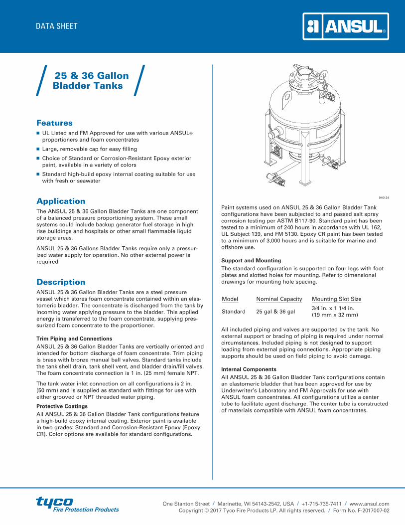
DescriptionANSUL 25 & 36 Gallon Bladder Tanks are a steel pressure vessel which stores foam concentrate contained within an elas-tomeric bladder. The concentrate is discharged from the tank by incoming water applying pressure to the bladder. This applied energy is transferred to the foam concentrate, supplying pres-surized foam concentrate to the proportioner.
Trim Piping and ConnectionsANSUL 25 & 36 Gallon Bladder Tanks are vertically oriented and intended for bottom discharge of foam concentrate. Trim piping is brass with bronze manual ball valves. Standard tanks include the tank shell drain, tank shell vent, and bladder drain/fill valves. The foam concentrate connection is 1 in. (25 mm) female NPT.
The tank water inlet connection on all configurations is 2 in. (50 mm) and is supplied as standard with fittings for use with either grooved or NPT threaded water piping.
Protective CoatingsAll ANSUL 25 & 36 Gallon Bladder Tank configurations feature a high-build epoxy internal coating. Exterior paint is available in two grades: Standard and Corrosion-Resistant Epoxy (Epoxy CR). Color options are available for standard configurations.
010124
Paint systems used on ANSUL 25 & 36 Gallon Bladder Tank configurations have been subjected to and passed salt spray corrosion testing per ASTM B117-90. Standard paint has been tested to a minimum of 240 hours in accordance with UL 162, UL Subject 139, and FM 5130. Epoxy CR paint has been tested to a minimum of 3,000 hours and is suitable for marine and offshore use.
Support and MountingThe standard configuration is supported on four legs with foot plates and slotted holes for mounting. Refer to dimensional drawings for mounting hole spacing.
Model Nominal Capacity Mounting Slot Size
Standard 25 gal & 36 gal3/4 in. x 1 1/4 in. (19 mm x 32 mm)
All included piping and valves are supported by the tank. No external support or bracing of piping is required under normal circumstances. Included piping is not designed to support loading from external piping connections. Appropriate piping supports should be used on field piping to avoid damage.
Internal ComponentsAll ANSUL 25 & 36 Gallon Bladder Tank configurations contain an elastomeric bladder that has been approved for use by Underwriter’s Laboratory and FM Approvals for use with ANSUL foam concentrates. All configurations utilize a center tube to facilitate agent discharge. The center tube is constructed of materials compatible with ANSUL foam concentrates.
25 & 36 Gallon Bladder Tanks
Description (Continued)
Thermal Relief ValveA thermal relief valve is available as an option for ANSUL bladder tanks. A thermal relief valve should be used when the bladder tank will be stored in an isolated/hydraulically locked condition in order to relieve pressure due to thermal expansion. This valve is factory set to 175 psi (12.1 bar) and it is recom-mended that the design pressure of the system be maintained at least 5 psi (0.3 bar) or 10% below the set pressure of the valve to avoid seat leakage and early valve maintenance. This valve is NOT a substitute for a properly sized ASME pressure relief valve to protect the entire system from overpressure.
ASME InformationAll ANSUL 25 & 36 Gallon Bladder Tank configurations are designed and constructed in accordance with the latest revi-sions to ASME Code Section VIII, Division 1 for unfired pressure vessels with a maximum allowable working pressure (MAWP) of 175 psi (12.1 bar) and tested to the pressure specified by the applicable codes and standards. Per ASME code, tanks with a 175 psi (12.1 bar) MAWP are tested to at least 230 psi (15.9 bar). All ANSUL bladder tanks are constructed of steel complying with ASME specifications. Tank heads are 2:1 elliptical unless otherwise specified.
All ANSUL 25 & 36 Gallon Bladder Tank configurations include a permanently affixed stainless steel ASME data plate. At a minimum, the data plate includes the following information: year of manufacture, maximum allowable working pressure (MAWP), nominal volume, part number, National Board number, minimum material thickness, minimum design metal tempera-ture (MDMT), and type of head used.
Approvals and CertificationsAll ANSUL 25 & 36 Gallon Bladder Tank configurations are UL Listed and FM Approved for use with various ANSUL foam concentrates. The UL mark and FM Approval diamond are applied at the factory along with a label identifying the ANSUL foam concentrate for use in the tank.
Every tank bears a permanently affixed ASME data plate showing the National Board number which identifies the tank as compliant with ASME code Section VIII, Division 1 for unfired pressure vessels.
ANSUL 25 & 36 Gallon Bladder Tank configurations are not CE marked. Under European Pressure Equipment Directive 2014/68/EU, tanks smaller than 200 gallons are acceptable based on sound engineering practices of ASME code and cannot be CE marked.
Operation & MaintenanceRefer to the ANSUL 25 & 36 Gallon Bladder Tanks / Hose Reel Station Operation & Maintenance Manual for detailed proce-dures on installation, operation, inspection, and maintenance. A printed copy of this manual is included with every tank.
Valve Position InformationValve Description* Normal Valve Position
Valve* No.
DescriptionManual System
Automatic System
1Manual Foam Concentrate Shutoff (Not Shown)
N.C. N.O.
2Water Supply Shut-Off (Not Shown)
N.C. N.O.
3 Tank Shell Vent Valve N.C. N.C.
4 Tank Shell Drain Valve N.C. N.C.
5 Bladder Drain Valve N.C. N.C.
6Automatic Foam Concentrate Isolation Valve (Not Shown)
– N.C.
N.C. – Normally Closed N.O. – Normally Open
In this arrangement, valves listed as (Not Shown) are either supplied as loose items or supplied by others.
*Not all valves supplied with all configurations
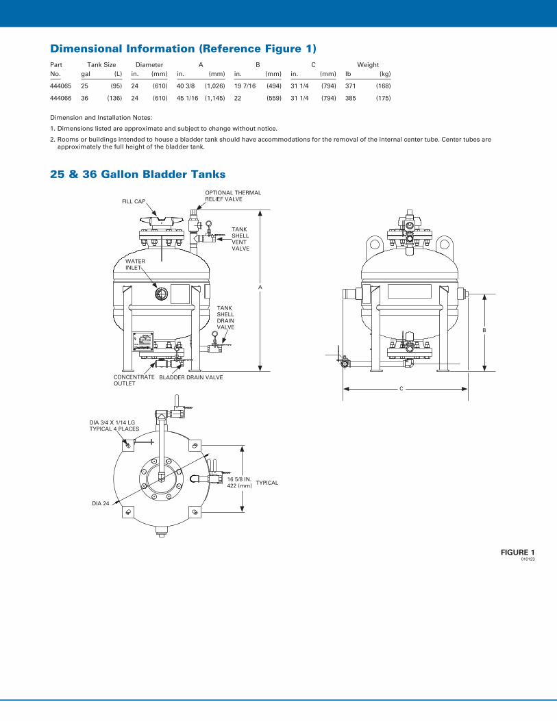
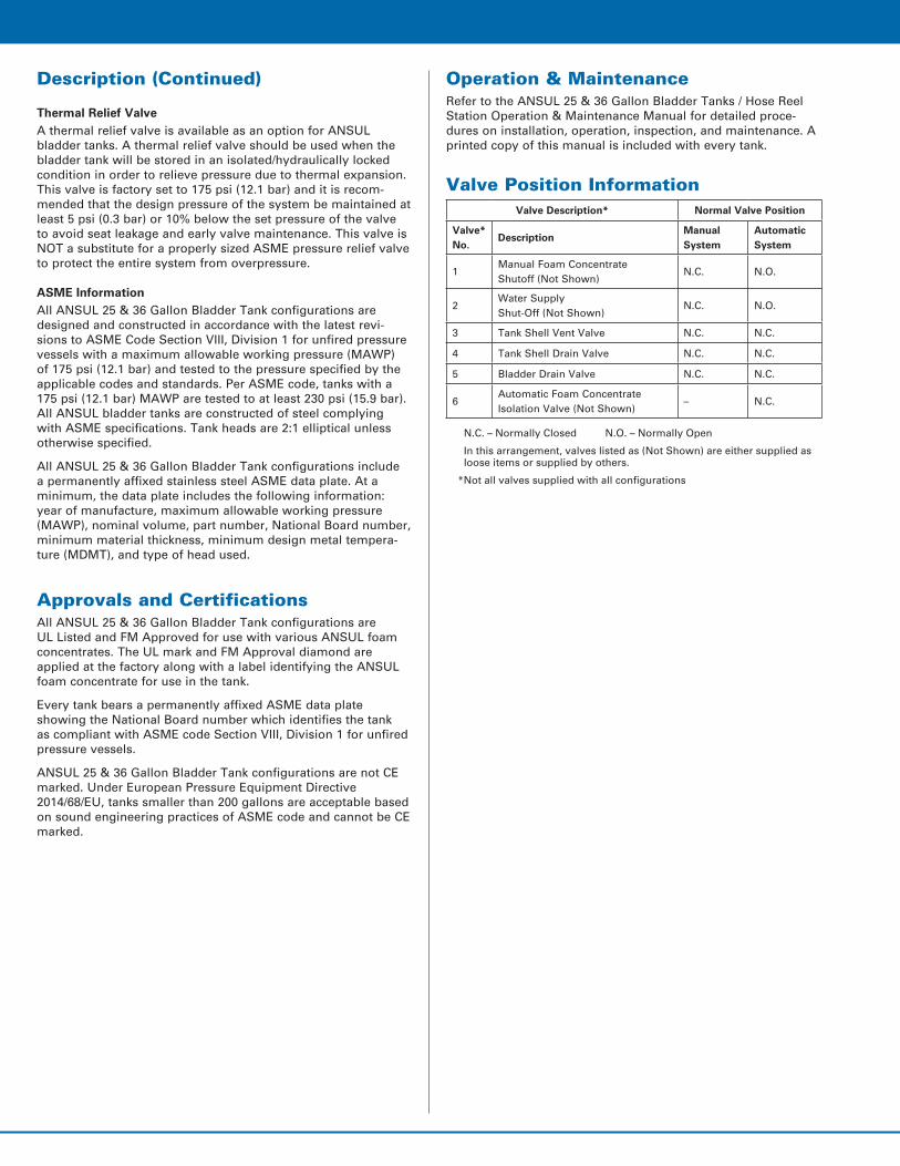
Dimensional Information (Reference Figure 1)Part No.
Tank Size gal (L)
Diameter in. (mm)
A in. (mm)
B in. (mm)
C in. (mm)
Weight lb (kg)
444065 25 (95) 24 (610) 40 3/8 (1,026) 19 7/16 (494) 31 1/4 (794) 371 (168)
444066 36 (136) 24 (610) 45 1/16 (1,145) 22 (559) 31 1/4 (794) 385 (175)
Dimension and Installation Notes:
1. Dimensions listed are approximate and subject to change without notice.
2. Rooms or buildings intended to house a bladder tank should have accommodations for the removal of the internal center tube. Center tubes are approximately the full height of the bladder tank.
25 & 36 Gallon Bladder Tanks
CONCENTRATE OUTLET
BLADDER DRAIN VALVE
A
B
C
TANK SHELL VENT VALVE
TANK SHELL DRAIN VALVE
OPTIONAL THERMAL RELIEF VALVEFILL CAP
DIA 3/4 X 1/14 LG TYPICAL 4 PLACES
WATER INLET
DIA 24
16 5/8 IN. 422 (mm) TYPICAL
FIGURE 1010123
Ordering InformationPlease specify the following when ordering:n Part Number for required 25 gal or 36 gal configurations
n Foam concentrate type to be used 1
n One option from each of the following categories 2:
Exterior PaintOption 1: Standard Option 2: CR Epoxy
Exterior Paint Color 3
Option 1: Red (RAL 3001)Option 2: Blue (RAL 5019)Option 3: Yellow (RAL 1021)Option 4: Other 4
Thermal Relief Valve 5
Option 1: No Thermal Relief ValveOption 2: Thermal Relief Valve Included
PackagingOption 1: Domestic PackagingOption 2: Export Crating
Ordering Notes:1. Tanks will be marked as UL Listed and/or FM Approved based on the
foam concentrate type specified. If foam concentrate type is not specified, the tank will not be marked as UL Listed or FM Approved.
2. For all other options categories, if an option is not specified, Option 1 will be used as the default.
3. UL Listing of paint systems is color-specific. The Red, Blue, and Yellow color shade options shown above are UL Listed. Contact TFPP Technical Services to determine if other color shades are UL Listed.
4. If “Other” is selected, the specific paint shade required must be supplied. Availability of the paint shade selected may impact lead time.
5. Set pressure is 175 psi (12.1 bar). Set pressure cannot exceed the design pressure of the tank per ASME code.
Expediting ServiceANSUL 36 Gallon Bladder Tanks, including most of the configu-rations and standard options listed, are available for optional expediting service. These tanks can be shipped in two to three weeks (depending on configuration selected) after order confir-mation. Contact Tyco Fire Protect Products Technical Services or an ANSUL Regional Sales Manager for additional information and limitations on this service.
Bladder Tank Ordering Part Numbers
Part NumberModel Description
Expediting Available
44406525 Gallon Bladder Tank
–
44406636 Gallon Bladder Tank
2 Weeks
Touch Up PaintTouch up paint for Red (RAL 3001) equipment is available in a convenient 7 ounce spray can. Touch up paint for other colors is not available in spray cans. Contact Tyco Fire Protect Products Technical Services for touch up paint in other colors.
Red (RAL 3001) Touch Up Paint – Part Number: 405581.
Custom EngineeringANSUL 25 & 36 Gallon Bladder Tanks can be customized to accommodate a variety of special requirements, including but not limited to alternate materials of construction, higher design pressures, space constraints, and seismic rated tanks. Contact Tyco Fire Protection Products Technical Services or an ANSUL Regional Sales Manager for additional information or to obtain a quote.
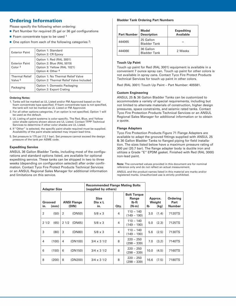
Flange AdaptersTyco Fire Protection Products Figure 71 Flange Adapters are available to adapt the grooved fittings supplied with ANSUL 25 & 36 Gallon Bladder Tanks to flanged piping for field installa-tion. The sizes listed below have a maximum pressure rating of 300 psi (20.7 bar). The flange adapter body is ductile iron and utilizes a Grade “E” EPDM gasket. Finished with Red (RAL 3000) non-lead paint. Note: The converted values provided in this document are for nominal reference only and do not reflect an actual measurement.
ANSUL and the product names listed in this material are marks and/or registered marks. Unauthorized use is strictly prohibited.
Adapter SizeRecommended Flange Mating Bolts (supplied by others)
Grooved in. (mm)
ANSI Flange (DIN)
Size Dia x L
in. Qty.
Bolt Torque Range lb-ft
(N·m)
Approx. Weight
lb (kg)
Ordering Part
Number
2 (50) 2 (DN50) 5/8 x 3 4110 – 140
(149 – 190) 3.0 (1.4) 7120TS
2 1/2 (65) 2 1/2 (DN65) 5/8 x 3 4110 – 140
(149 – 190) 5.0 (2.3) 7125TS
3 (80) 3 (DN80) 5/8 x 3 4110 – 140
(149 – 190) 5.6 (2.5) 7130TS
4 (100) 4 (DN100) 3/4 x 3 1/2 8220 – 250
(298 – 339) 7.0 (3.2) 7140TS
6 (150) 6 (DN150) 3/4 x 3 1/2 8220 – 250
(298 – 339) 10.0 (4.5) 7160TS
8 (200) 8 (DN200) 3/4 x 3 1/2 8220 – 250
(298 – 339) 16.6 (7.5) 7180TS