2450 SourceMeter SMU Instrument - tek.com · Datasheet 6 TEK.COM Free Instrument Control Start-up...
14
The 2450 is Keithley’s next-generation SourceMeter source measure unit (SMU) instrument that truly brings Ohm’s law (current, voltage, and resistance) testing right to your fingertips. Its innovative graphical user interface (GUI) and advanced, capacitive touchscreen technology allow intuitive usage and minimize the learning curve to enable engineers and scientists to learn faster, work smarter, and invent easier. The 2450 is the SMU for everyone: a versatile instrument, particularly well-suited for characterizing modern scaled semiconductors, nano-scale devices and materials, organic semiconductors, printed electronics, and other small-geometry and low-power devices. All this combined with Keithley SMU precision and accuracy allows users to Touch, Test, Invent ® with the new favorite go-to instrument in the lab for years to come. 2450 SourceMeter ® SMU Instrument Datasheet A Tektronix Company Key Features • Capabilities of analyzers, curve tracers, and I-V systems at a fraction of their cost • Five-inch, high resolution capacitive touchscreen GUI • 0.012% basic measure accuracy with 6½-digit resolution • Enhanced sensitivity with new 20mV and 10nA source/measure ranges • Source and sink (four-quadrant) operation • Four “Quickset” modes for fast setup and measurements • Built-in, context-sensitive front panel help • Front panel input banana jacks; rear panel input triaxial connections • 2450 SCPI and TSP ® scripting programming modes • 2400 SCPI-compatible programming mode • Front panel USB memory port for data/programming/ configuration I/Ole capacitance effects 2450 main home screen.
Transcript of 2450 SourceMeter SMU Instrument - tek.com · Datasheet 6 TEK.COM Free Instrument Control Start-up...
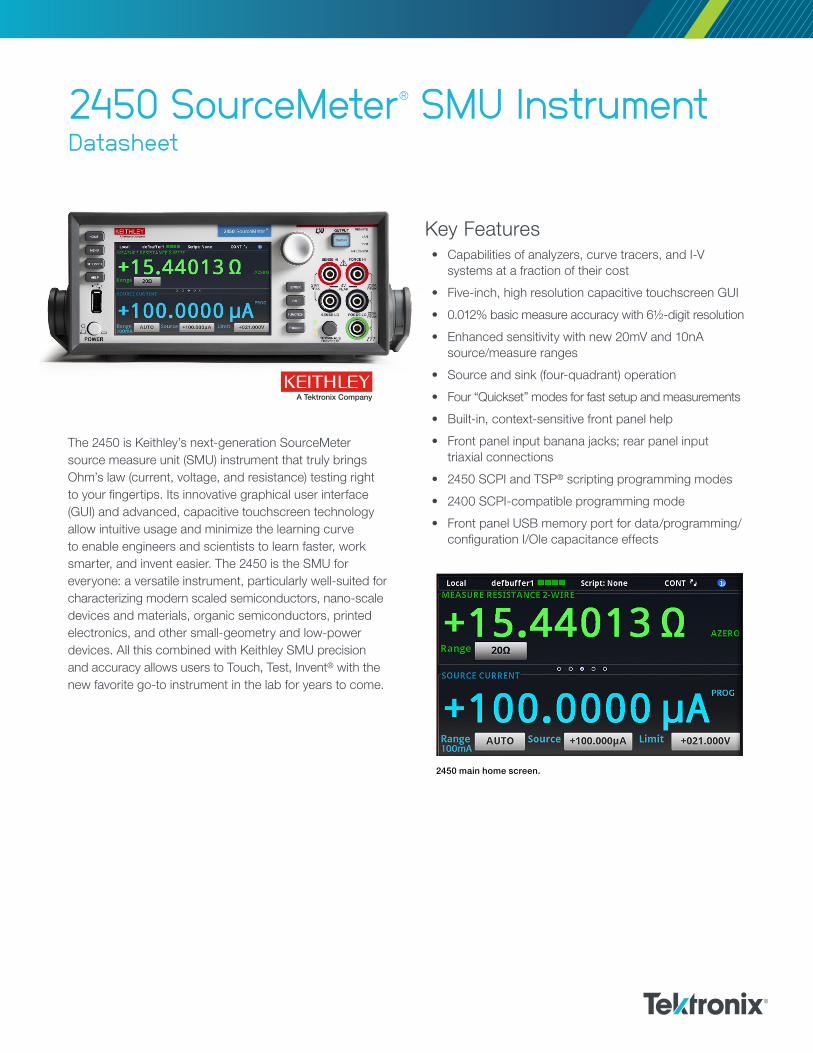
The 2450 is Keithley’s next-generation SourceMeter source measure unit (SMU) instrument that truly brings Ohm’s law (current, voltage, and resistance) testing right to your fingertips. Its innovative graphical user interface (GUI) and advanced, capacitive touchscreen technology allow intuitive usage and minimize the learning curve to enable engineers and scientists to learn faster, work smarter, and invent easier. The 2450 is the SMU for everyone: a versatile instrument, particularly well-suited for characterizing modern scaled semiconductors, nano-scale devices and materials, organic semiconductors, printed electronics, and other small-geometry and low-power devices. All this combined with Keithley SMU precision and accuracy allows users to Touch, Test, Invent® with the new favorite go-to instrument in the lab for years to come.
2450 SourceMeter ® SMU InstrumentDatasheet
A Tektronix Company
Key Features• Capabilities of analyzers, curve tracers, and I-V
systems at a fraction of their cost
• Five-inch, high resolution capacitive touchscreen GUI
• 0.012% basic measure accuracy with 6½-digit resolution
• Enhanced sensitivity with new 20mV and 10nA source/measure ranges
• Source and sink (four-quadrant) operation
• Four “Quickset” modes for fast setup and measurements
• Built-in, context-sensitive front panel help
• Front panel input banana jacks; rear panel input triaxial connections
• 2450 SCPI and TSP® scripting programming modes
• 2400 SCPI-compatible programming mode
• Front panel USB memory port for data/programming/configuration I/Ole capacitance effects
2450 main home screen.
Datasheet
TEK.COM2
Learn Faster, Work Smarter, and Invent EasierUnlike conventional instruments with dedicated push-button technology and small, obscure, limited-character displays, the 2450 features a five-inch, full-color, high-resolution touchscreen that facilitates ease of use, learning, and optimizes overall speed and productivity. A simple icon-based menu structure reduces configuration steps by as much as 50 percent and eliminates the cumbersome multi-layer menu structures typically used on soft-key instruments. Built-in, context-sensitive help enables intuitive operation and minimizes the need to review a separate manual. These capabilities combined with its application versatility make the 2450 the SMU instrument inherently easy to use for basic and advanced measurement applications, regardless of your experience level with SMU instruments.
2450 icon-based menu.
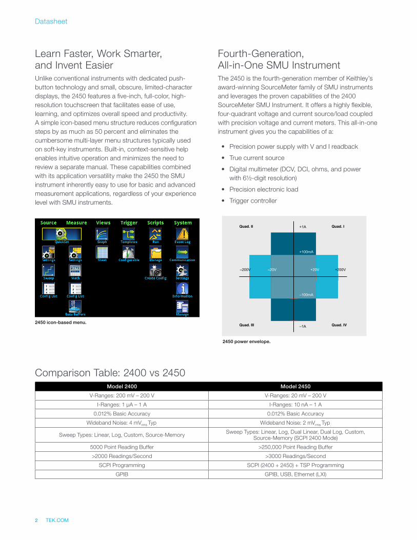
Fourth-Generation, All-in-One SMU InstrumentThe 2450 is the fourth- generation member of Keithley’s award-winning SourceMeter family of SMU instruments and leverages the proven capabilities of the 2400 SourceMeter SMU Instrument. It offers a highly flexible, four-quadrant voltage and current source/load coupled with precision voltage and current meters. This all-in-one instrument gives you the capabilities of a:
• Precision power supply with V and I readback
• True current source
• Digital multimeter (DCV, DCI, ohms, and power with 6½-digit resolution)
• Precision electronic load
• Trigger controller
+20V–20V–200V +200V
+100mA
+1A
–100mA
–1A
Quad. II Quad. I
Quad. III Quad. IV
2450 power envelope.
Model 2400 Model 2450
V-Ranges: 200 mV – 200 V V-Ranges: 20 mV – 200 V
I-Ranges: 1 μA – 1 A I-Ranges: 10 nA – 1 A
0.012% Basic Accuracy 0.012% Basic Accuracy
Wideband Noise: 4 mVrms Typ. Wideband Noise: 2 mVrms Typ.
Sweep Types: Linear, Log, Custom, Source-Memory Sweep Types: Linear, Log, Dual Linear, Dual Log, Custom, Source-Memory (SCPI 2400 Mode)
5000 Point Reading Buffer >250,000 Point Reading Buffer
>2000 Readings/Second >3000 Readings/Second
SCPI Programming SCPI (2400 + 2450) + TSP Programming
GPIB GPIB, USB, Ethernet (LXI)
Comparison Table: 2400 vs 2450
TEK.COM 3
2450 SourceMeter® SMU Instrument
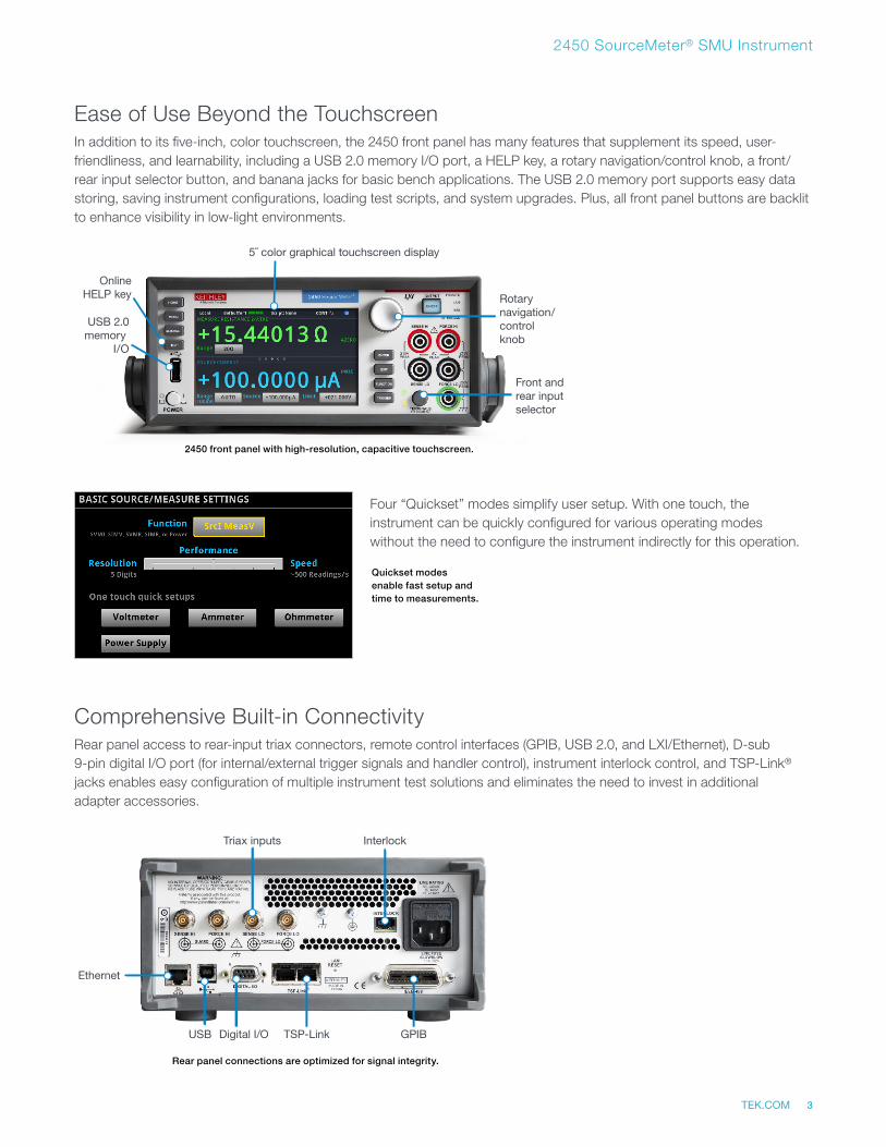
Quickset modes enable fast setup and time to measurements.
USB 2.0memory
I/O
Front andrear input selector
Rotarynavigation/control knob
5˝ color graphical touchscreen display
OnlineHELP key
2450 front panel with high-resolution, capacitive touchscreen.
Ease of Use Beyond the TouchscreenIn addition to its five-inch, color touchscreen, the 2450 front panel has many features that supplement its speed, user-friendliness, and learnability, including a USB 2.0 memory I/O port, a HELP key, a rotary navigation/control knob, a front/rear input selector button, and banana jacks for basic bench applications. The USB 2.0 memory port supports easy data storing, saving instrument configurations, loading test scripts, and system upgrades. Plus, all front panel buttons are backlit to enhance visibility in low-light environments.
Four “Quickset” modes simplify user setup. With one touch, the instrument can be quickly configured for various operating modes without the need to configure the instrument indirectly for this operation.
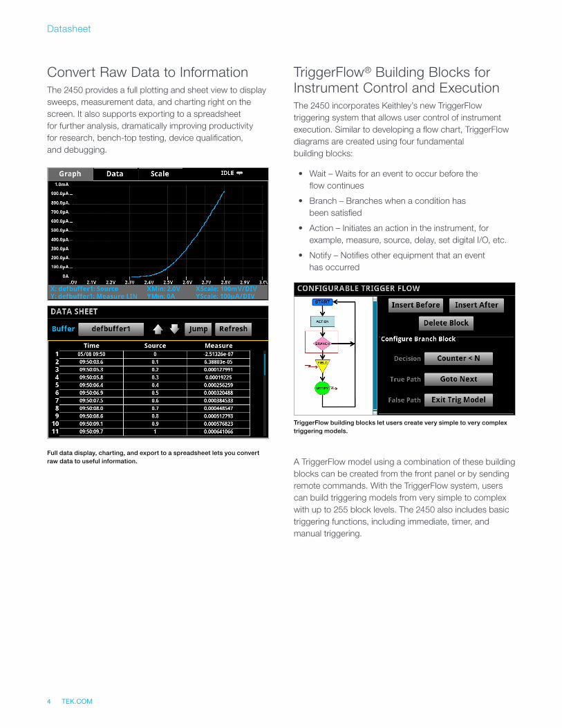
Comprehensive Built-in ConnectivityRear panel access to rear-input triax connectors, remote control interfaces (GPIB, USB 2.0, and LXI/Ethernet), D-sub 9-pin digital I/O port (for internal/external trigger signals and handler control), instrument interlock control, and TSP-Link® jacks enables easy configuration of multiple instrument test solutions and eliminates the need to invest in additional adapter accessories.
Ethernet
Triax inputs
Digital I/O TSP-Link GPIB
Interlock
USB
Rear panel connections are optimized for signal integrity.
Datasheet
TEK.COM4
Convert Raw Data to InformationThe 2450 provides a full plotting and sheet view to display sweeps, measurement data, and charting right on the screen. It also supports exporting to a spreadsheet for further analysis, dramatically improving productivity for research, bench-top testing, device qualification, and debugging.
TriggerFlow® Building Blocks for Instrument Control and ExecutionThe 2450 incorporates Keithley’s new TriggerFlow triggering system that allows user control of instrument execution. Similar to developing a flow chart, TriggerFlow diagrams are created using four fundamental building blocks:
• Wait – Waits for an event to occur before the flow continues
• Branch – Branches when a condition has been satisfied
• Action – Initiates an action in the instrument, for example, measure, source, delay, set digital I/O, etc.
• Notify – Notifies other equipment that an event has occurred
A TriggerFlow model using a combination of these building blocks can be created from the front panel or by sending remote commands. With the TriggerFlow system, users can build triggering models from very simple to complex with up to 255 block levels. The 2450 also includes basic triggering functions, including immediate, timer, and manual triggering.
TriggerFlow building blocks let users create very simple to very complex triggering models.
Full data display, charting, and export to a spreadsheet lets you convert raw data to useful information.
TEK.COM 5
2450 SourceMeter® SMU Instrument
Unmatched System Integration and Programming FlexibilityWhen the 2450 is integrated as part of a multi-channel I-V test system, the Test Script Processor (TSP®) embedded scripting capability allows test scripts to be run by the instrument, enabling the user to create powerful measurement applications with significantly reduced development times. TSP technology also offers channel expansion without a mainframe. Keithley’s TSP-Link® channel expansion bus, which uses a 100 Base T Ethernet cable, connects multiple 2450 instruments and other TSP instruments such as Keithley’s Series 2600B SourceMeter SMU instruments and Series 3700A Switch/Multimeter systems in a master-slave configuration that behaves as one integrated system. The TSP-Link expansion bus supports up to 32 units per GPIB or IP address, making it easy to scale a system to fit an application’s particular requirements.
The 2450 also includes a SCPI programming mode that optimizes the instrument’s new features, as well as a SCPI 2400 mode that provides backwards compatibility with the existing 2400 SourceMeter instrument. Not only does this preserve your 2400 investment but it also eliminates re-work normally associated with upgrading to a new instrument with new capabilities.
Parallel Test CapabilityWith the TSP technology in the 2450, multiple devices can be tested in parallel to meet the needs of device research, advanced semiconductor lab applications, and even high throughput production test. This parallel testing capability enables each instrument in the system to run its own complete test sequence, creating a fully multi-threaded test environment. The number of tests that can be run in parallel on a 2450 can be as high as the number of instruments in the system.
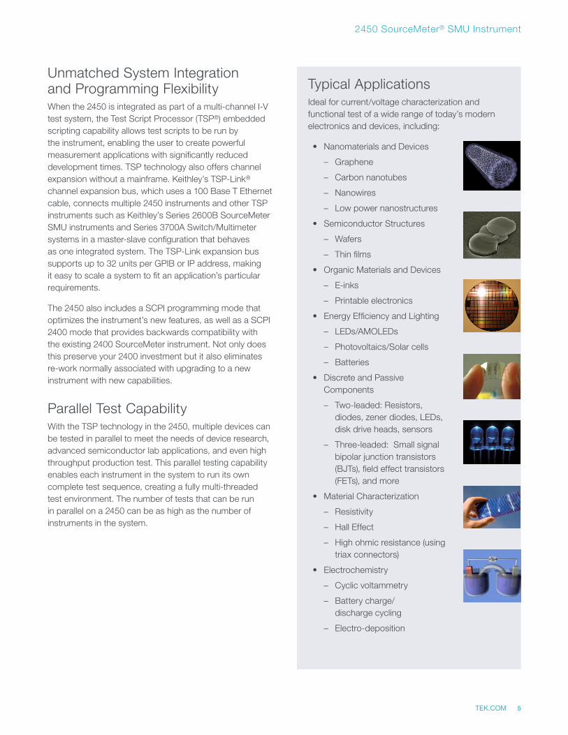
Typical ApplicationsIdeal for current/voltage characterization and functional test of a wide range of today’s modern electronics and devices, including:
• Nanomaterials and Devices
– Graphene
– Carbon nanotubes
– Nanowires
– Low power nanostructures
• Semiconductor Structures
– Wafers
– Thin films
• Organic Materials and Devices
– E-inks
– Printable electronics
• Energy Efficiency and Lighting
– LEDs/AMOLEDs
– Photovoltaics/Solar cells
– Batteries
• Discrete and Passive Components
– Two-leaded: Resistors, diodes, zener diodes, LEDs, disk drive heads, sensors
– Three-leaded: Small signal bipolar junction transistors (BJTs), field effect transistors (FETs), and more
• Material Characterization
– Resistivity
– Hall Effect
– High ohmic resistance (using triax connectors)
• Electrochemistry
– Cyclic voltammetry
– Battery charge/discharge cycling
– Electro-deposition
Datasheet
TEK.COM6
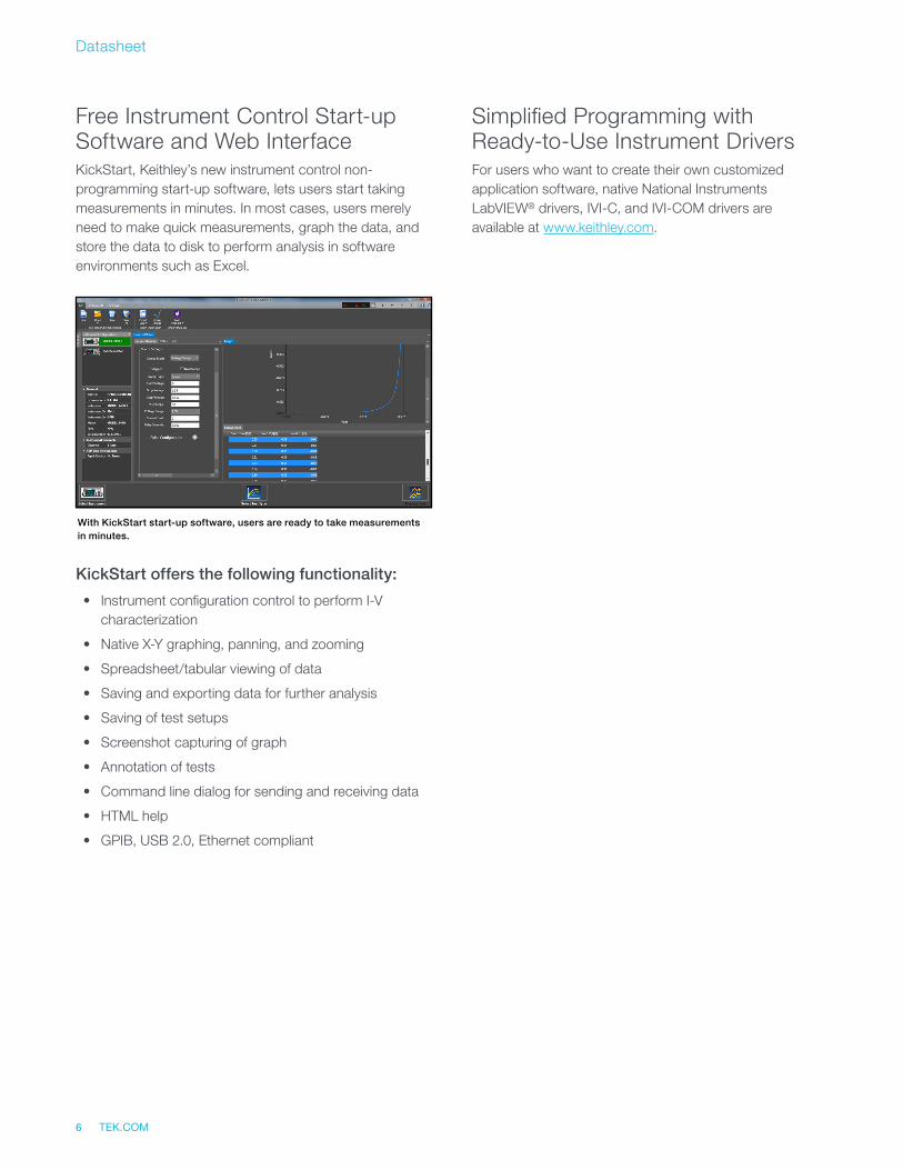
Free Instrument Control Start-up Software and Web InterfaceKickStart, Keithley’s new instrument control non-programming start-up software, lets users start taking measurements in minutes. In most cases, users merely need to make quick measurements, graph the data, and store the data to disk to perform analysis in software environments such as Excel.
KickStart offers the following functionality:
• Instrument configuration control to perform I-V characterization
• Native X-Y graphing, panning, and zooming
• Spreadsheet/tabular viewing of data
• Saving and exporting data for further analysis
• Saving of test setups
• Screenshot capturing of graph
• Annotation of tests
• Command line dialog for sending and receiving data
• HTML help
• GPIB, USB 2.0, Ethernet compliant
With KickStart start-up software, users are ready to take measurements in minutes.
Simplified Programming with Ready-to-Use Instrument DriversFor users who want to create their own customized application software, native National Instruments LabVIEW® drivers, IVI-C, and IVI-COM drivers are available at www.keithley.com.
TEK.COM 7
2450 SourceMeter® SMU Instrument
Specifications
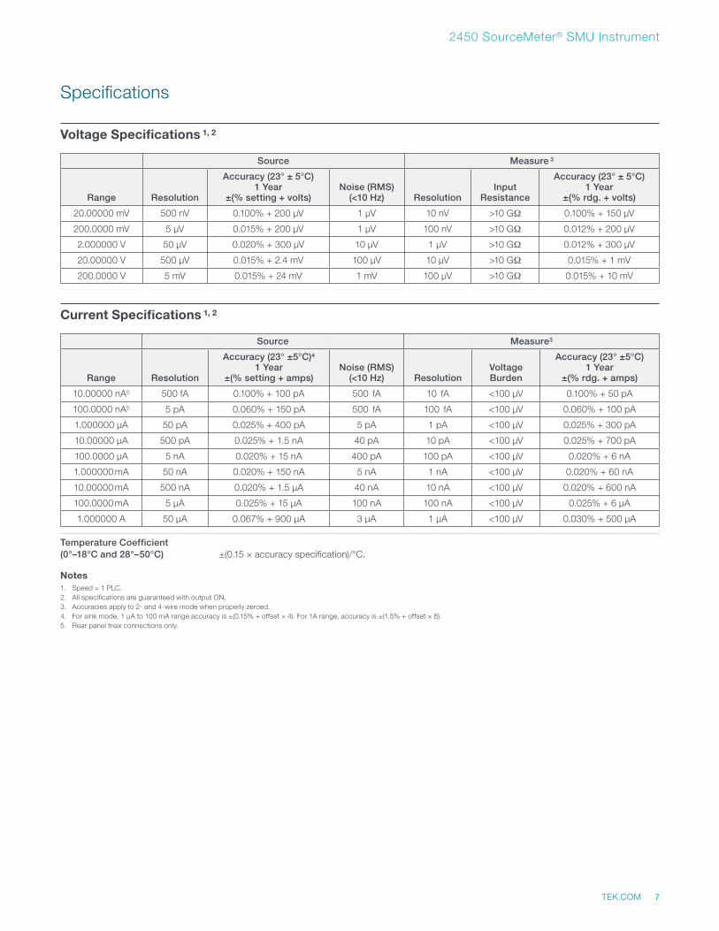
Voltage Specifications 1, 2
Source Measure 3
Range Resolution
Accuracy (23° ± 5°C) 1 Year
±(% setting + volts)Noise (RMS)
(<10 Hz) ResolutionInput
Resistance
Accuracy (23° ± 5°C) 1 Year
±(% rdg. + volts)
20.00000 mV 500 nV 0.100% + 200 μV 1 μV 10 nV >10 GΩ 0.100% + 150 μV
200.0000 mV 5 μV 0.015% + 200 μV 1 μV 100 nV >10 GΩ 0.012% + 200 μV
2.000000 V 50 μV 0.020% + 300 μV 10 μV 1 μV >10 GΩ 0.012% + 300 μV
20.00000 V 500 μV 0.015% + 2.4 mV 100 μV 10 μV >10 GΩ 0.015% + 1 mV
200.0000 V 5 mV 0.015% + 24 mV 1 mV 100 μV >10 GΩ 0.015% + 10 mV
Current Specifications 1, 2
Source Measure3
Range Resolution
Accuracy (23° ±5°C)4 1 Year
±(% setting + amps)Noise (RMS)
(<10 Hz) ResolutionVoltage Burden
Accuracy (23° ±5°C) 1 Year
±(% rdg. + amps)
10.00000 nA5 500 fA 0.100% + 100 pA 500 fA 10 fA <100 μV 0.100% + 50 pA
100.0000 nA5 5 pA 0.060% + 150 pA 500 fA 100 fA <100 μV 0.060% + 100 pA
1.000000 μA 50 pA 0.025% + 400 pA 5 pA 1 pA <100 μV 0.025% + 300 pA
10.00000 μA 500 pA 0.025% + 1.5 nA 40 pA 10 pA <100 μV 0.025% + 700 pA
100.0000 μA 5 nA 0.020% + 15 nA 400 pA 100 pA <100 μV 0.020% + 6 nA
1.000000 mA 50 nA 0.020% + 150 nA 5 nA 1 nA <100 μV 0.020% + 60 nA
10.00000 mA 500 nA 0.020% + 1.5 μA 40 nA 10 nA <100 μV 0.020% + 600 nA
100.0000 mA 5 μA 0.025% + 15 μA 100 nA 100 nA <100 μV 0.025% + 6 μA
1.000000 A 50 μA 0.067% + 900 μA 3 μA 1 μA <100 μV 0.030% + 500 μA
Temperature Coefficient(0°–18°C and 28°–50°C) ±(0.15 × accuracy specification)/°C.
Notes1. Speed = 1 PLC.2. All specifications are guaranteed with output ON.3. Accuracies apply to 2- and 4-wire mode when properly zeroed.4. For sink mode, 1 μA to 100 mA range accuracy is ±(0.15% + offset × 4). For 1A range, accuracy is ±(1.5% + offset × 8).5. Rear panel triax connections only.
Datasheet
TEK.COM8
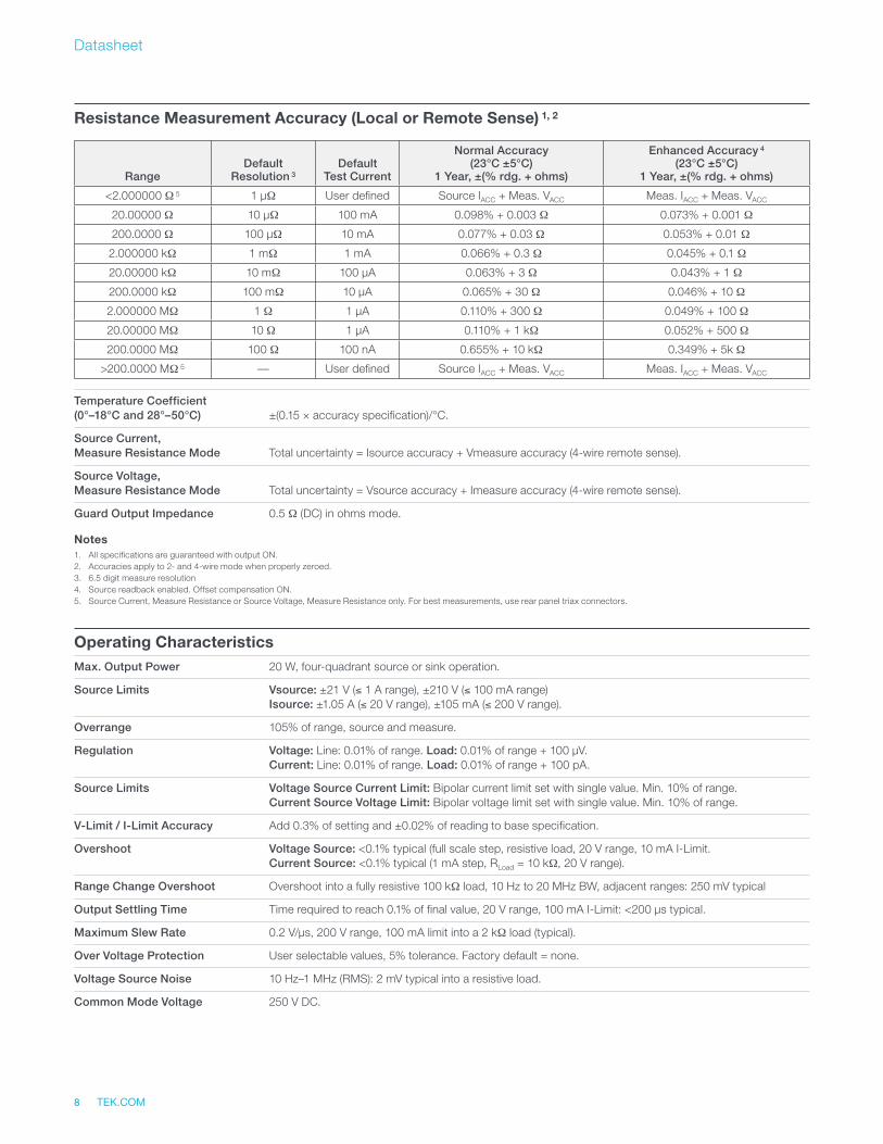
Resistance Measurement Accuracy (Local or Remote Sense) 1, 2
RangeDefault
Resolution 3Default
Test Current
Normal Accuracy (23°C ±5°C)
1 Year, ±(% rdg. + ohms)
Enhanced Accuracy 4 (23°C ±5°C)
1 Year, ±(% rdg. + ohms)
<2.000000 Ω 5 1 μΩ User defined Source IACC + Meas. VACC Meas. IACC + Meas. VACC
20.00000 Ω 10 μΩ 100 mA 0.098% + 0.003 Ω 0.073% + 0.001 Ω
200.0000 Ω 100 μΩ 10 mA 0.077% + 0.03 Ω 0.053% + 0.01 Ω
2.000000 kΩ 1 mΩ 1 mA 0.066% + 0.3 Ω 0.045% + 0.1 Ω
20.00000 kΩ 10 mΩ 100 μA 0.063% + 3 Ω 0.043% + 1 Ω
200.0000 kΩ 100 mΩ 10 μA 0.065% + 30 Ω 0.046% + 10 Ω
2.000000 MΩ 1 Ω 1 μA 0.110% + 300 Ω 0.049% + 100 Ω
20.00000 MΩ 10 Ω 1 μA 0.110% + 1 kΩ 0.052% + 500 Ω
200.0000 MΩ 100 Ω 100 nA 0.655% + 10 kΩ 0.349% + 5k Ω
>200.0000 MΩ 5 — User defined Source IACC + Meas. VACC Meas. IACC + Meas. VACC
Temperature Coefficient(0°–18°C and 28°–50°C) ±(0.15 × accuracy specification)/°C.
Source Current,Measure Resistance Mode Total uncertainty = Isource accuracy + Vmeasure accuracy (4-wire remote sense).
Source Voltage,Measure Resistance Mode Total uncertainty = Vsource accuracy + Imeasure accuracy (4-wire remote sense).
Guard Output Impedance 0.5 Ω (DC) in ohms mode.
Notes1. All specifications are guaranteed with output ON.2. Accuracies apply to 2- and 4-wire mode when properly zeroed.3. 6.5 digit measure resolution4. Source readback enabled. Offset compensation ON.5. Source Current, Measure Resistance or Source Voltage, Measure Resistance only. For best measurements, use rear panel triax connectors.
Operating CharacteristicsMax. Output Power 20 W, four-quadrant source or sink operation.
Source Limits Vsource: ±21 V (≤ 1 A range), ±210 V (≤ 100 mA range) Isource: ±1.05 A (≤ 20 V range), ±105 mA (≤ 200 V range).
Overrange 105% of range, source and measure.
Regulation Voltage: Line: 0.01% of range. Load: 0.01% of range + 100 μV. Current: Line: 0.01% of range. Load: 0.01% of range + 100 pA.
Source Limits Voltage Source Current Limit: Bipolar current limit set with single value. Min. 10% of range. Current Source Voltage Limit: Bipolar voltage limit set with single value. Min. 10% of range.
V-Limit / I-Limit Accuracy Add 0.3% of setting and ±0.02% of reading to base specification.
Overshoot Voltage Source: <0.1% typical (full scale step, resistive load, 20 V range, 10 mA I-Limit. Current Source: <0.1% typical (1 mA step, RLoad = 10 kΩ, 20 V range).
Range Change Overshoot Overshoot into a fully resistive 100 kΩ load, 10 Hz to 20 MHz BW, adjacent ranges: 250 mV typical
Output Settling Time Time required to reach 0.1% of final value, 20 V range, 100 mA I-Limit: <200 μs typical.
Maximum Slew Rate 0.2 V/μs, 200 V range, 100 mA limit into a 2 kΩ load (typical).
Over Voltage Protection User selectable values, 5% tolerance. Factory default = none.
Voltage Source Noise 10 Hz–1 MHz (RMS): 2 mV typical into a resistive load.
Common Mode Voltage 250 V DC.
TEK.COM 9
2450 SourceMeter® SMU Instrument
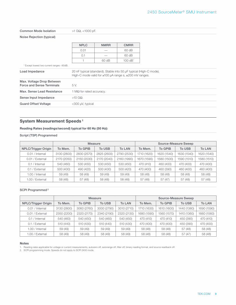
Common Mode Isolation >1 GΩ, <1000 pF.
Noise Rejection (typical)
NPLC NMRR CMRR
0.01 — 60 dB
0.1 — 60 dB
1 60 dB 100 dB*
* Except lowest two current ranges ~90dB.
Load Impedance 20 nF typical (standard). Stable into 50 μF typical (High-C mode). High-C mode valid for ≥100 μA range s, ≥200 mV ranges.
Max. Voltage Drop BetweenForce and Sense Terminals 5 V.
Max. Sense Lead Resistance 1 MΩ for rated accuracy.
Sense Input Impedance >10 GΩ.
Guard Offset Voltage <300 μV, typical
System Measurement Speeds 1
Reading Rates (readings/second) typical for 60 Hz (50 Hz):
Script (TSP) Programmed
Measure Source-Measure Sweep
NPLC/Trigger Origin To Mem. To GPIB To USB To LAN To Mem. To GPIB To USB To LAN
0.01 / Internal 3130 (2800) 2830 (2570) 2825 (2600) 2790 (2530) 1710 (1620) 1620 (1540) 1630 (1540) 1620 (1540)
0.01 / External 2170 (2050) 2150 (2030) 2170 (2040) 2160 (1990) 1670 (1590) 1580 (1500) 1590 (1510) 1580 (1510)
0.1 / Internal 540 (460) 530 (450) 530 (450) 530 (450) 470 (410) 460 (400) 470 (400) 470 (400)
0.1 / External 500 (430) 490 (420) 500 (430) 500 (420) 470 (400) 460 (390) 460 (400) 460 (400)
1.00 / Internal 59 (49) 58 (49) 59 (49) 59 (49) 58 (48) 58 (48) 58 (48) 58 (48)
1.00 / External 58 (48) 57 (48) 58 (48) 58 (48) 57 (48) 57 (47) 57 (48) 57 (48)
SCPI Programmed 2
Measure Source-Measure Sweep
NPLC/Trigger Origin To Mem. To GPIB To USB To LAN To Mem. To GPIB To USB To LAN
0.01 / Internal 3130 (2800) 3060 (2760) 3000 (2790) 3010 (2710) 1710 (1630) 1610 (1600) 1440 (1380) 1690 (1590)
0.01 / External 2350 (2200) 2320 (2170) 2340 (2190) 2320 (2130) 1680 (1590) 1560 (1570) 1410 (1360) 1660 (1560)
0.1 / Internal 540 (460) 540 (450) 540 (460) 540 (450) 470 (410) 470 (410) 450 (390) 470 (410)
0.1 / External 510 (440) 510 (430) 510 (440) 510 (430) 470 (400) 470 (400) 450 (390) 470 (400)
1.00 / Internal 59 (49) 59 (49) 59 (49) 59 (49) 58 (48) 58 (48) 57 (48) 58 (48)
1.00 / External 58 (49) 58 (49) 58 (49) 58 (49) 58 (48) 58 (48) 57 (47) 58 (48)
Notes1. Reading rates applicable for voltage or current measurements, autozero off, autorange off, filter off, binary reading format, and source readback off.2. SCPI programming mode. Speeds do not apply to SCPI 2400 mode.
Datasheet
TEK.COM10
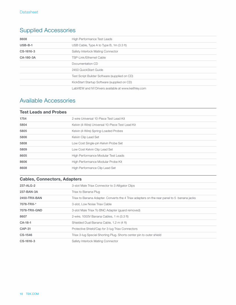
Supplied Accessories8608 High Performance Test Leads
USB-B-1 USB Cable, Type A to Type B, 1m (3.3 ft)
CS-1616-3 Safety Interlock Mating Connector
CA-180-3A TSP-Link/Ethernet Cable
Documentation CD
2450 QuickStart Guide
Test Script Builder Software (supplied on CD)
KickStart Startup Software (supplied on CD)
LabVIEW and IVI Drivers available at www.keithley.com
Available Accessories
Test Leads and Probes1754 2-wire Universal 10-Piece Test Lead Kit
5804 Kelvin (4-Wire) Universal 10-Piece Test Lead Kit
5805 Kelvin (4-Wire) Spring-Loaded Probes
5806 Kelvin Clip Lead Set
5808 Low Cost Single-pin Kelvin Probe Set
5809 Low Cost Kelvin Clip Lead Set
8605 High Performance Modular Test Leads
8606 High Performance Modular Probe Kit
8608 High Performance Clip Lead Set
Cables, Connectors, Adapters237-ALG-2 3-slot Male Triax Connector to 3 Alligator Clips
237-BAN-3A Triax to Banana Plug
2450-TRX-BAN Triax to Banana Adapter. Converts the 4 Triax adapters on the rear panel to 5 banana jacks
7078-TRX-* 3-slot, Low Noise Triax Cable
7078-TRX-GND 3-slot Male Triax To BNC Adapter (guard removed)
8607 2-wire, 1000V Banana Cables, 1 m (3.3 ft)
CA-18-1 Shielded Dual Banana Cable, 1.2 m (4 ft)
CAP-31 Protective Shield/Cap for 3-lug Triax Connectors
CS-1546 Triax 3-lug Special Shorting Plug. Shorts center pin to outer shield
CS-1616-3 Safety Interlock Mating Connector
TEK.COM 11
2450 SourceMeter® SMU Instrument
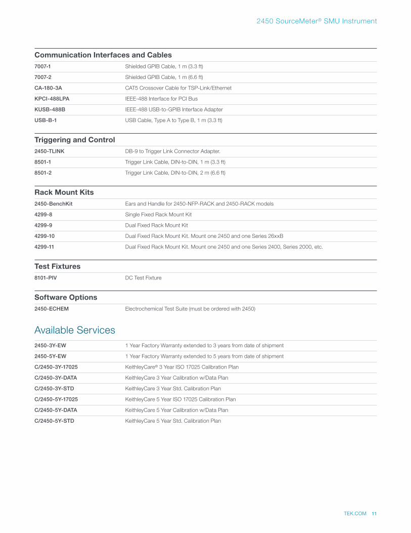
Communication Interfaces and Cables7007-1 Shielded GPIB Cable, 1 m (3.3 ft)
7007-2 Shielded GPIB Cable, 1 m (6.6 ft)
CA-180-3A CAT5 Crossover Cable for TSP-Link/Ethernet
KPCI-488LPA IEEE-488 Interface for PCI Bus
KUSB-488B IEEE-488 USB-to-GPIB Interface Adapter
USB-B-1 USB Cable, Type A to Type B, 1 m (3.3 ft)
Triggering and Control2450-TLINK DB-9 to Trigger Link Connector Adapter.
8501-1 Trigger Link Cable, DIN-to-DIN, 1 m (3.3 ft)
8501-2 Trigger Link Cable, DIN-to-DIN, 2 m (6.6 ft)
Rack Mount Kits2450-BenchKit Ears and Handle for 2450-NFP-RACK and 2450-RACK models
4299-8 Single Fixed Rack Mount Kit
4299-9 Dual Fixed Rack Mount Kit
4299-10 Dual Fixed Rack Mount Kit. Mount one 2450 and one Series 26xxB
4299-11 Dual Fixed Rack Mount Kit. Mount one 2450 and one Series 2400, Series 2000, etc.
Test Fixtures8101-PIV DC Test Fixture
Software Options2450-ECHEM Electrochemical Test Suite (must be ordered with 2450)
Available Services2450-3Y-EW 1 Year Factory Warranty extended to 3 years from date of shipment
2450-5Y-EW 1 Year Factory Warranty extended to 5 years from date of shipment
C/2450-3Y-17025 KeithleyCare® 3 Year ISO 17025 Calibration Plan
C/2450-3Y-DATA KeithleyCare 3 Year Calibration w/Data Plan
C/2450-3Y-STD KeithleyCare 3 Year Std. Calibration Plan
C/2450-5Y-17025 KeithleyCare 5 Year ISO 17025 Calibration Plan
C/2450-5Y-DATA KeithleyCare 5 Year Calibration w/Data Plan
C/2450-5Y-STD KeithleyCare 5 Year Std. Calibration Plan
Datasheet
TEK.COM12
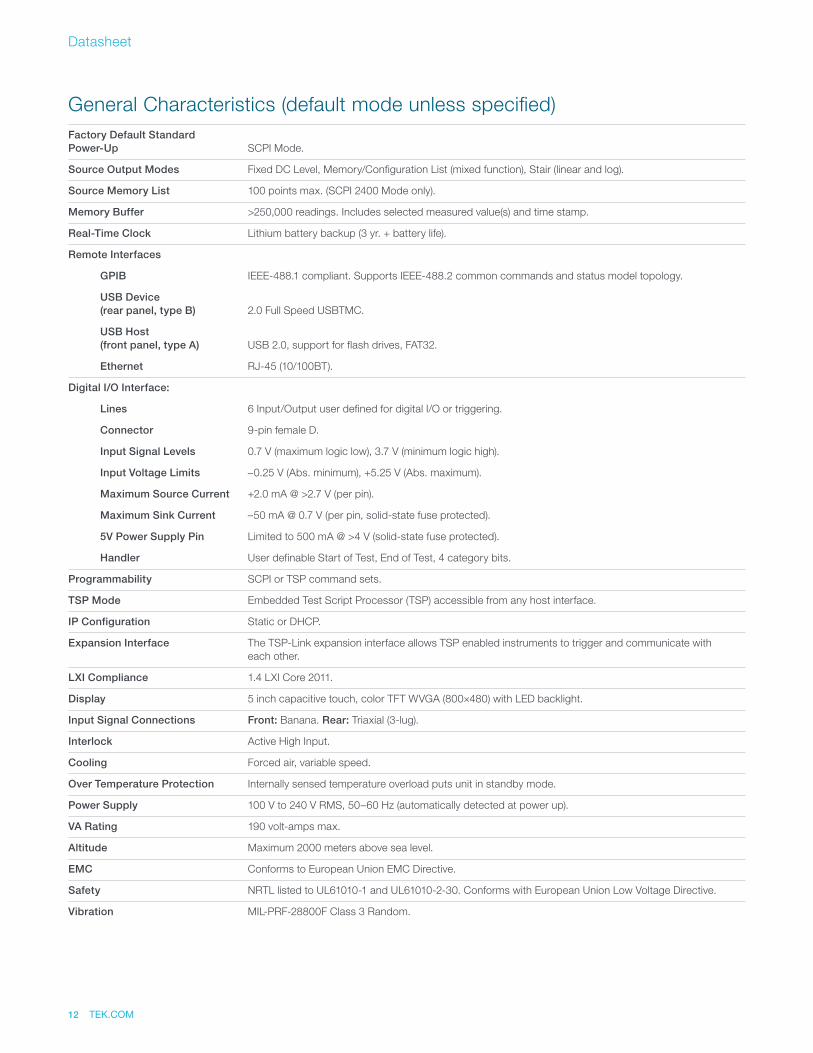
General Characteristics (default mode unless specified)Factory Default StandardPower-Up SCPI Mode.
Source Output Modes Fixed DC Level, Memory/Configuration List (mixed function), Stair (linear and log).
Source Memory List 100 points max. (SCPI 2400 Mode only).
Memory Buffer >250,000 readings. Includes selected measured value(s) and time stamp.
Real-Time Clock Lithium battery backup (3 yr. + battery life).
Remote Interfaces
GPIB IEEE-488.1 compliant. Supports IEEE-488.2 common commands and status model topology.
USB Device(rear panel, type B) 2.0 Full Speed USBTMC.
USB Host(front panel, type A) USB 2.0, support for flash drives, FAT32.
Ethernet RJ-45 (10/100BT).
Digital I/O Interface:
Lines 6 Input/Output user defined for digital I/O or triggering.
Connector 9-pin female D.
Input Signal Levels 0.7 V (maximum logic low), 3.7 V (minimum logic high).
Input Voltage Limits –0.25 V (Abs. minimum), +5.25 V (Abs. maximum).
Maximum Source Current +2.0 mA @ >2.7 V (per pin).
Maximum Sink Current –50 mA @ 0.7 V (per pin, solid-state fuse protected).
5V Power Supply Pin Limited to 500 mA @ >4 V (solid-state fuse protected).
Handler User definable Start of Test, End of Test, 4 category bits.
Programmability SCPI or TSP command sets.
TSP Mode Embedded Test Script Processor (TSP) accessible from any host interface.
IP Configuration Static or DHCP.
Expansion Interface The TSP-Link expansion interface allows TSP enabled instruments to trigger and communicate with each other.
LXI Compliance 1.4 LXI Core 2011.
Display 5 inch capacitive touch, color TFT WVGA (800×480) with LED backlight.
Input Signal Connections Front: Banana. Rear: Triaxial (3-lug).
Interlock Active High Input.
Cooling Forced air, variable speed.
Over Temperature Protection Internally sensed temperature overload puts unit in standby mode.
Power Supply 100 V to 240 V RMS, 50–60 Hz (automatically detected at power up).
VA Rating 190 volt-amps max.
Altitude Maximum 2000 meters above sea level.
EMC Conforms to European Union EMC Directive.
Safety NRTL listed to UL61010-1 and UL61010-2-30. Conforms with European Union Low Voltage Directive.
Vibration MIL-PRF-28800F Class 3 Random.
TEK.COM 13
2450 SourceMeter® SMU Instrument
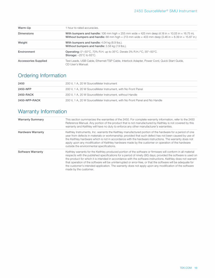
Warm-Up 1 hour to rated accuracies.
Dimensions With bumpers and handle: 106 mm high × 255 mm wide × 425 mm deep (4.18 in × 10.05 in × 16.75 in). Without bumpers and handle: 88 mm high × 213 mm wide × 403 mm deep (3.46 in × 8.39 in × 15.87 in.)
Weight With bumpers and handle: 4.04 kg (8.9 lbs.). Without bumpers and handle: 3.58 kg (7.9 lbs.).
Environment Operating: 0°–50°C, 70% R.H. up to 35°C. Derate 3% R.H./°C, 35°–50°C. Storage: –25°C to 65°C.
Accessories Supplied Test Leads, USB Cable, Ethernet/TSP Cable, Interlock Adapter, Power Cord, Quick Start Guide, CD User’s Manual.
Ordering Information2450 200 V, 1 A, 20 W SourceMeter Instrument
2450-NFP 200 V, 1 A, 20 W SourceMeter Instrument, with No Front Panel
2450-RACK 200 V, 1 A, 20 W SourceMeter Instrument, without Handle
2450-NFP-RACK 200 V, 1 A, 20 W SourceMeter Instrument, with No Front Panel and No Handle
Warranty InformationWarranty Summary This section summarizes the warranties of the 2450. For complete warranty information, refer to the 2450
Reference Manual. Any portion of the product that is not manufactured by Keithley is not covered by this warranty and Keithley will have no duty to enforce any other manufacturer’s warranties.
Hardware Warranty Keithley Instruments, Inc. warrants the Keithley manufactured portion of the hardware for a period of one year from defects in materials or workmanship; provided that such defect has not been caused by use of the Keithley hardware which is not in accordance with the hardware instructions. The warranty does not apply upon any modification of Keithley hardware made by the customer or operation of the hardware outside the environmental specifications.
Software Warranty Keithley warrants for the Keithley produced portion of the software or firmware will conform in all material respects with the published specifications for a period of ninety (90) days; provided the software is used on the product for which it is intended in accordance with the software instructions. Keithley does not warrant that operation of the software will be uninterrupted or error-free, or that the software will be adequate for the customer’s intended application. The warranty does not apply upon any modification of the software made by the customer.
Contact Information: Australia* 1 800 709 465
Austria 00800 2255 4835
Balkans, Israel, South Africa and other ISE Countries +41 52 675 3777
Belgium* 00800 2255 4835
Brazil +55 (11) 3759 7627
Canada 1 800 833 9200
Central East Europe / Baltics +41 52 675 3777
Central Europe / Greece +41 52 675 3777
Denmark +45 80 88 1401
Finland +41 52 675 3777
France* 00800 2255 4835
Germany* 00800 2255 4835
Hong Kong 400 820 5835
India 000 800 650 1835
Indonesia 007 803 601 5249
Italy 00800 2255 4835
Japan 81 (3) 6714 3010
Luxembourg +41 52 675 3777
Malaysia 1 800 22 55835
Mexico, Central/South America and Caribbean 52 (55) 56 04 50 90
Middle East, Asia, and North Africa +41 52 675 3777
The Netherlands* 00800 2255 4835
New Zealand 0800 800 238
Norway 800 16098
People’s Republic of China 400 820 5835
Philippines 1 800 1601 0077
Poland +41 52 675 3777
Portugal 80 08 12370
Republic of Korea +82 2 6917 5000
Russia / CIS +7 (495) 6647564
Singapore 800 6011 473
South Africa +41 52 675 3777
Spain* 00800 2255 4835
Sweden* 00800 2255 4835
Switzerland* 00800 2255 4835
Taiwan 886 (2) 2656 6688
Thailand 1 800 011 931
United Kingdom / Ireland* 00800 2255 4835
USA 1 800 833 9200
Vietnam 12060128
* European toll-free number. If not accessible, call: +41 52 675 3777
Find more valuable resources at TEK.COM
Copyright © Tektronix. All rights reserved. Tektronix products are covered by U.S. and foreign patents, issued and pending. Information in this publication supersedes that in all previously published material. Specification and price change privileges reserved. TEKTRONIX and TEK are registered trademarks of Tektronix, Inc. All other trade names referenced are the service marks, trademarks or registered trademarks of their respective companies. 100316. AH 1KW-60904-0