2440
16
Schweitzer Engineering Laboratories, Inc. SEL-2440 DPAC Data Sheet SEL-2440 Discrete Programmable Automation Controller Complete System for Control and Monitoring Major Features and Benefits Fast and Powerful I/O ➤ Utilize an exceptional and compact combination of inputs, outputs, and communications. ➤ Analyze system events with inputs and other events timed to the microsecond. ➤ Synchronize control with outputs that are synchronized to IRIG-B time. ➤ Perform actions quickly with a processing interval of 2 ms and an input to output interval of 7 ms. ➤ Program new features with logic, latches, timers, counters, edge-triggers, and math functions. ➤ Ensure safe operation by using an input with logic programmed for local/remote control. Convenient Maintenance and Support ➤ LEDs provide status for every I/O point and communications port. ➤ Removable terminal blocks make installation and replacement quick and efficient. ➤ Positive retention connectors ensure that connections are not lost due to sagging cables. ➤ Front-panel management port makes device management convenient. Flexible Communications and Integration ➤ Communicate with DNP3, Modbus, and IEC 61850 protocols over Ethernet and serial connections. Direct and select-before-operate (SBO) outputs are supported. ➤ Automate systems with flexible communication options that provide easy integration with SCADA. ➤ Configure easily with preprogrammed register or object maps and front-panel DIP switches. ➤ Alternatively, configure with ACSELERATOR QuickSet ® SEL-5030 Software. SEL Quality, Standards, and Global Support ➤ Designed and tested for harsh physical and electrical environments. ➤ Designed and tested to operate with dc grounded batteries and capacitive loads, and to trip breakers and interrupt inductive loads. ➤ Superior specification compliance, high reliability, low price, and worldwide, ten-year warranty. Rack Panel Surface DIN Rail 32 Inputs 16 Outputs 4 Ports (Standard) SEL-2411 SEL-2411 SEL-2411 . . . . . . . . . RTAC DPAC PAC SEL-2440 SEL-2440 SEL-2440 SEL-2440 Serial or Ethernet Communications SEL-3530
-
Upload
highcom-mectel-ingenieria -
Category
Documents
-
view
238 -
download
0
description
SEL Quality, Standards, and Global Support ➤ Designed and tested for harsh physical and electrical environments. ➤ Designed and tested to operate with dc grounded batteries and capacitive loads, and to trip breakers and interrupt inductive loads. ➤ Superior specification compliance, high reliability, low price, and worldwide, ten-year warranty. 32 Inputs 16 Outputs 4 Ports (Standard) DPAC RTAC PAC SEL-2440 DPAC Data Sheet Schweitzer Engineering Laboratories, Inc. SEL-3530 . . . . . .
Transcript of 2440
Schweitzer Engineering Laboratories, Inc. SEL-2440 DPAC Data Sheet
SEL-2440 Discrete Programmable Automation Controller
Complete System for Control and Monitoring
Major Features and BenefitsFast and Powerful I/O
➤ Utilize an exceptional and compact combination of inputs, outputs, and communications.
➤ Analyze system events with inputs and other events timed to the microsecond.
➤ Synchronize control with outputs that are synchronized to IRIG-B time.
➤ Perform actions quickly with a processing interval of 2 ms and an input to output interval of 7 ms.
➤ Program new features with logic, latches, timers, counters, edge-triggers, and math functions.
➤ Ensure safe operation by using an input with logic programmed for local/remote control.
Convenient Maintenance and Support➤ LEDs provide status for every I/O point and
communications port.➤ Removable terminal blocks make installation and
replacement quick and efficient.➤ Positive retention connectors ensure that
connections are not lost due to sagging cables.➤ Front-panel management port makes device
management convenient.
Flexible Communications and Integration➤ Communicate with DNP3, Modbus, and IEC
61850 protocols over Ethernet and serial connections. Direct and select-before-operate (SBO) outputs are supported.
➤ Automate systems with flexible communication options that provide easy integration with SCADA.
➤ Configure easily with preprogrammed register or object maps and front-panel DIP switches.
➤ Alternatively, configure with ACSELERATOR QuickSet® SEL-5030 Software.
SEL Quality, Standards, and Global Support➤ Designed and tested for harsh physical and
electrical environments. ➤ Designed and tested to operate with dc grounded
batteries and capacitive loads, and to trip breakers and interrupt inductive loads.
➤ Superior specification compliance, high reliability, low price, and worldwide, ten-year warranty.
Rack Panel Surface DIN Rail
32 Inputs16 Outputs4 Ports(Standard)
SEL-2411 SEL-2411 SEL-2411
. . .
. . .
. . .
RTAC
DPAC
PAC
SEL-2440 SEL-2440
SEL-2440 SEL-2440
Serial or Ethernet Communications
SEL-3530
SEL-2440 DPAC Data Sheet Schweitzer Engineering Laboratories, Inc.
2
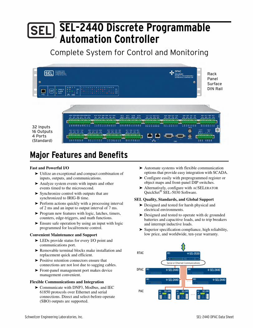
Product SummaryThe SEL-2440 Discrete Programmable Automation Controller (DPAC) withstands harsh physical and electricalenvironments and is built and tested to meet mission-critical IEEE and IEC protective relay standards. Apply the DPACto satisfy stand-alone or distributed input, output, and communications needs. Figure 1 shows the DPAC functionality.
Functional Diagram
Figure 1 Functional Diagram
Configuration➤ Easy Mode. Set address and communications
parameters with DIP switches.➤ Flexible Mode. Access additional flexibility using
ACSELERATOR QuickSet software, shown in the following figure.
Figure 2 ACSELERATOR QuickSet Launchpad
Inputs/OutputsDPAC devices can be ordered with different I/O andinput voltage ratings as shown in the following tables.
I/O Quantity Options
I/O Input Voltage Options
Communications and TimeMany communications ports and protocols are provided.
Figure 3 Rear-Panel Communications and IRIG-B Ports
Protocol Processing
Security
ProgrammableAutomation
Engine(2 ms processing)
Sequential Events Recorder
SerialEthernet
Switch
MAC
EthernetIRIG-BOUT
IRIG-BIN
Inpu
t Pro
cess
or (1
ms)
Mic
rose
cond
Tim
er
Outp
ut R
elay
s (4
ms)
32DiscreteInputs
(typical)
16DiscreteOutputs(typical)
7 ms Delay
2
Inputs Outputs
Standard
Option 1
Option 2
Option 3
32
16
48
16
16
32
0
32 (16 Standard and16 High-Current Interruption)
Digital Input Rating
24 Vac/Vdc
48 Vac/Vdc
125 Vac/Vdc
Port Port Interface
PORT F USB 2.0 physical interface, serial port (e.g., COM1) software interface
PORT 1 Ethernet with switch/failover (copper or fiber)
PORT 2 Serial (EIA-232, EIA-485, V-pin fiber, or ST fiber)
PORT 3 Serial (EIA-232)
Serial Ethernet
DNP3 Yes Yes
Modbus® Yes Yes
IEC 61850 Yes
MIRRORED BITS® Yes
SEL Fast Message Yes
Schweitzer Engineering Laboratories, Inc. SEL-2440 DPAC Data Sheet
3
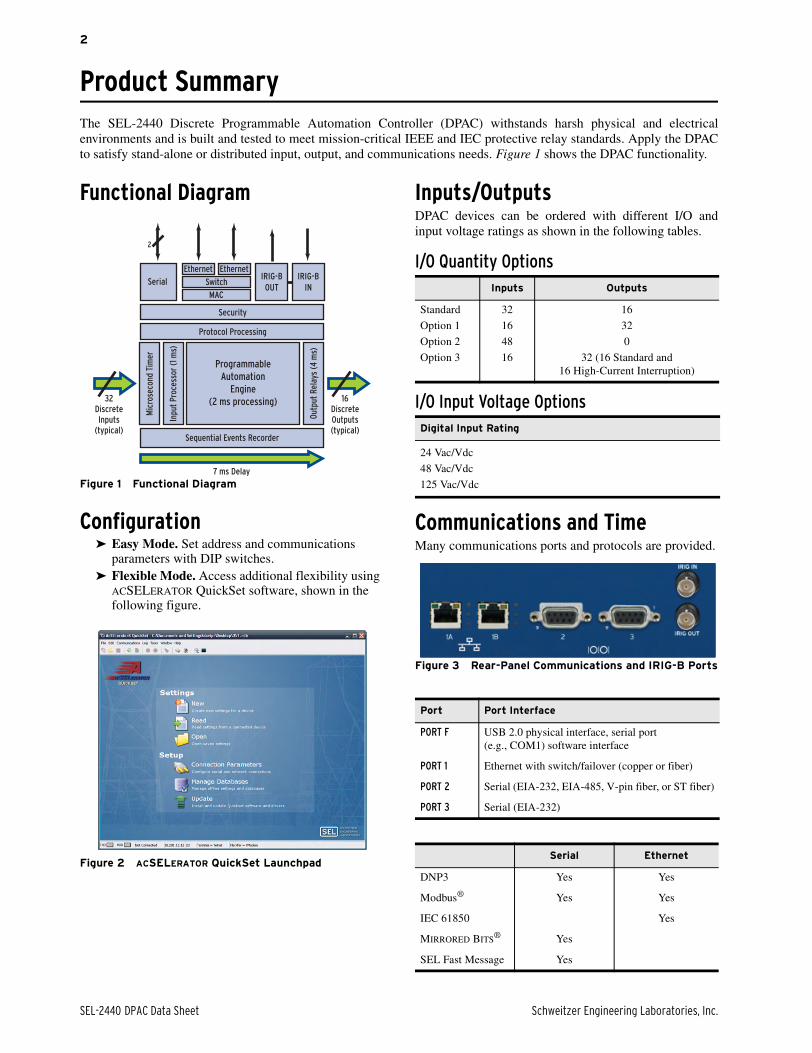
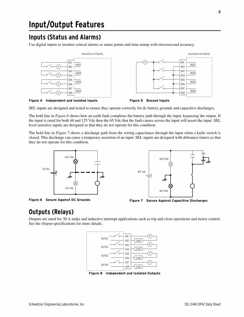
Input/Output FeaturesInputs (Status and Alarms)Use digital inputs to monitor critical alarms or status points and time-stamp with microsecond accuracy.
Figure 4 Independent and Isolated Inputs Figure 5 Bussed Inputs
SEL inputs are designed and tested to ensure they operate correctly for dc battery grounds and capacitive discharges.
The bold line in Figure 6 shows how an earth fault completes the battery path through the input, bypassing the output. Ifthe input is rated for both 48 and 125 Vdc then the 65 Vdc that the fault causes across the input will assert the input. SELlevel-sensitive inputs are designed so that they do not operate for this condition.
The bold line in Figure 7 shows a discharge path from the wiring capacitance through the input when a knife switch isclosed. This discharge can cause a temporary assertion of an input. SEL inputs are designed with debounce timers so thatthey do not operate for this condition.
Figure 6 Secure Against DC Grounds Figure 7 Secure Against Capacitive Discharges
Outputs (Relays)Outputs are rated for 30 A make and inductive interrupt applications such as trip and close operations and motor control.See the Output specifications for more details.
Figure 8 Independent and Isolated Outputs
V B02
B01IN201
V B04
B03IN202
V B06
B05IN203
V B08
B07IN204
Insensitive to Polarity
VIN201
IN202
IN203
IN204
Insensitive to Polarity
B02
B01
B04
B03
B06
B05
B08
B07
+62.5 Vdc
125 Vdc
-62.5 Vdc
125 Vdc
+62.5 Vdc
-62.5 Vdc
V
V
V
V
OUT101
OUT102
OUT103
OUT104
A02
A01
A04
A03
A06
A05
A08
A07
Load
Load
Load
Load
SEL-2440 DPAC Data Sheet Schweitzer Engineering Laboratories, Inc.
4
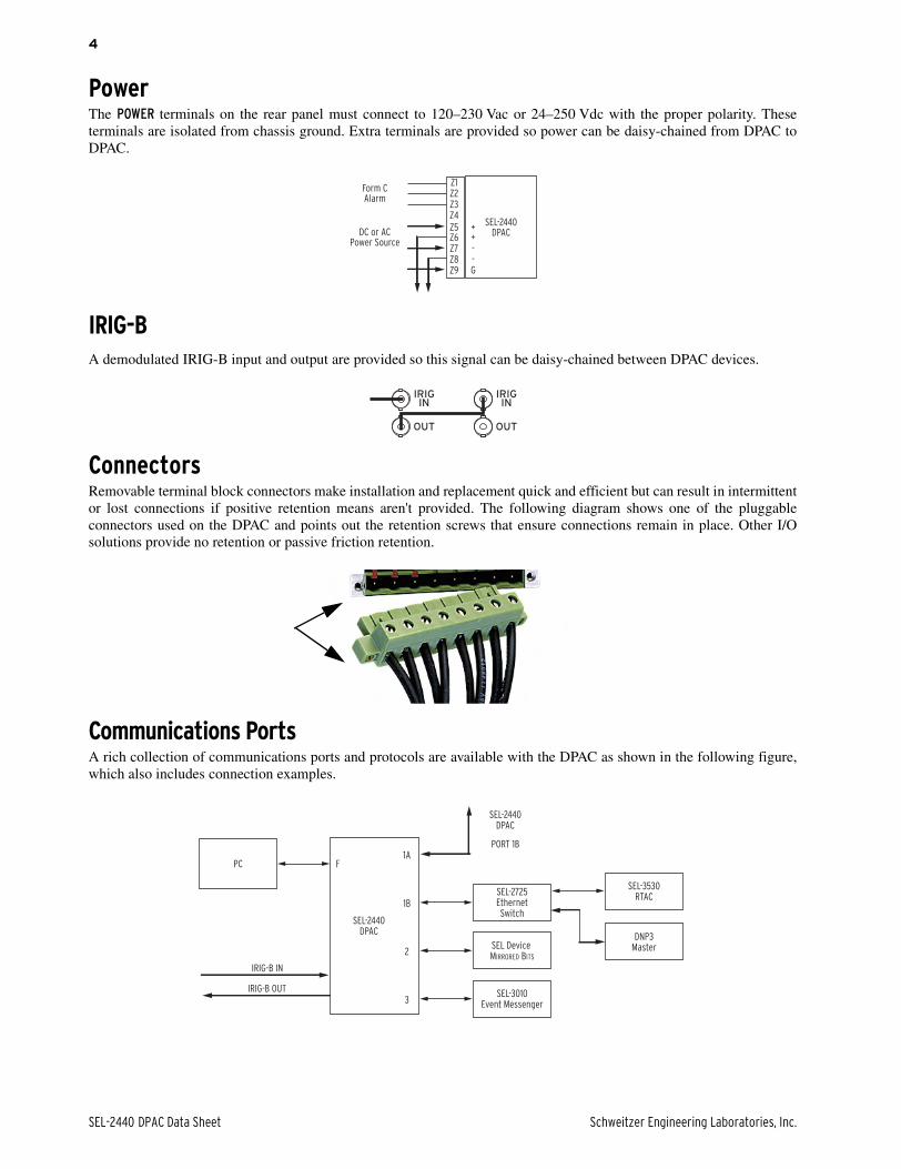
PowerThe POWER terminals on the rear panel must connect to 120–230 Vac or 24–250 Vdc with the proper polarity. Theseterminals are isolated from chassis ground. Extra terminals are provided so power can be daisy-chained from DPAC toDPAC.
IRIG-BA demodulated IRIG-B input and output are provided so this signal can be daisy-chained between DPAC devices.
ConnectorsRemovable terminal block connectors make installation and replacement quick and efficient but can result in intermittentor lost connections if positive retention means aren't provided. The following diagram shows one of the pluggableconnectors used on the DPAC and points out the retention screws that ensure connections remain in place. Other I/Osolutions provide no retention or passive friction retention.
Communications PortsA rich collection of communications ports and protocols are available with the DPAC as shown in the following figure,which also includes connection examples.
Form CAlarm
DC or ACPower Source
Z1
SEL-2440DPAC
Z2Z3Z4
Z5Z6Z7Z8Z9
++--G
OUT
INIRIG
OUT
INIRIG
PC
SEL-2440DPAC
SEL-2725EthernetSwitch
SEL Device MIRRORED BITS
SEL-3010Event Messenger3
2
1B
1AF
SEL-2440DPAC
PORT 1B
SEL-3530RTAC
DNP3Master
IRIG-B OUT
IRIG-B IN
Schweitzer Engineering Laboratories, Inc. SEL-2440 DPAC Data Sheet
5
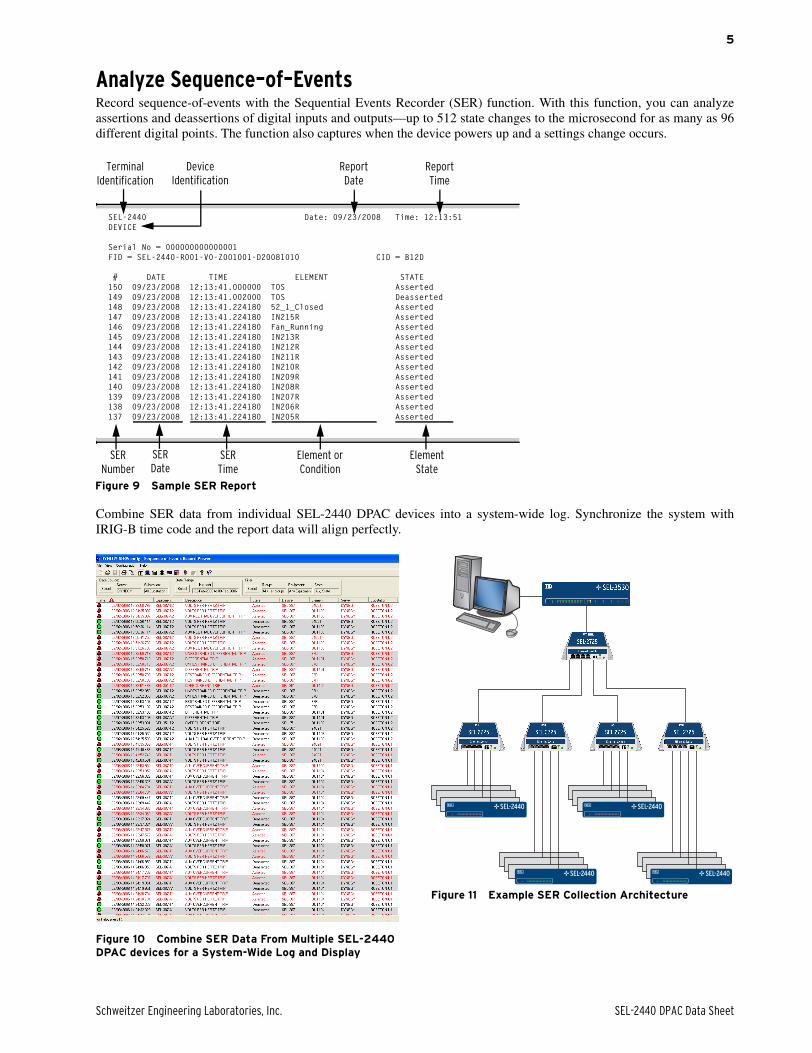
Analyze Sequence–of–EventsRecord sequence-of-events with the Sequential Events Recorder (SER) function. With this function, you can analyzeassertions and deassertions of digital inputs and outputs—up to 512 state changes to the microsecond for as many as 96different digital points. The function also captures when the device powers up and a settings change occurs.
Combine SER data from individual SEL-2440 DPAC devices into a system-wide log. Synchronize the system withIRIG-B time code and the report data will align perfectly.
Figure 10 Combine SER Data From Multiple SEL-2440 DPAC devices for a System-Wide Log and Display
Figure 11 Example SER Collection Architecture
Figure 9 Sample SER Report
SEL-2440 Date: 09/23/2008 Time: 12:13:51DEVICE
Serial No = 000000000000001FID = SEL-2440-R001-V0-Z001001-D20081010 CID = B12D
# DATE TIME ELEMENT STATE150 09/23/2008 12:13:41.000000 TOS Asserted149 09/23/2008 12:13:41.002000 TOS Deasserted148 09/23/2008 12:13:41.224180 52_1_Closed Asserted147 09/23/2008 12:13:41.224180 IN215R Asserted146 09/23/2008 12:13:41.224180 Fan_Running Asserted145 09/23/2008 12:13:41.224180 IN213R Asserted144 09/23/2008 12:13:41.224180 IN212R Asserted143 09/23/2008 12:13:41.224180 IN211R Asserted142 09/23/2008 12:13:41.224180 IN210R Asserted141 09/23/2008 12:13:41.224180 IN209R Asserted140 09/23/2008 12:13:41.224180 IN208R Asserted139 09/23/2008 12:13:41.224180 IN207R Asserted138 09/23/2008 12:13:41.224180 IN206R Asserted137 09/23/2008 12:13:41.224180 IN205R Asserted
SERNumber
Element or Condition
Element State
SERDate
SERTime
Report Date
Report Time
Device Identification
Terminal Identification
SEL-2440SEL-2440
SEL-2440SEL-2440
SEL-2440 DPAC Data Sheet Schweitzer Engineering Laboratories, Inc.
6
Automation FeaturesFlexible Control Logic and Integration FeaturesEases ConfigurationThe DPAC does not require special communicationssoftware. Use any system that emulates a standard termi-nal system for engineering access to the device.
Simplifies CommunicationsThe SEL-2440 is equipped with three independentlyoperated serial ports. Establish communication by con-necting computers, modems, protocol converters, print-ers, an SEL Communications Processor, SCADA serialport, and an RTU for local or remote communication.Apply an SEL communications processor as the hub of astar network, with point-to-point fiber or copper connec-tion between the hub and the SEL-2440.
Supports Standard ProtocolsAs with most SEL devices, the DPAC comes standardwith the communications protocols listed below.
➤ DNP3➤ Modbus➤ SEL ASCII➤ SEL Compressed ASCII➤ SEL Fast Meter➤ SEL Fast Operate➤ SEL Fast SER➤ SEL Fast Message➤ SEL MIRRORED BITS
Simplifies SCADASEL devices provide propriety but open, binary “fast”protocols. These protocols are self-describing and areinterleaved with ASCII protocols on the same port. Sim-plify configuration, minimize communications wiring,and improve performance between the DPAC and otherdevices (e.g., communications processors) and with theseprotocols.
Performs Logic and MathEliminate PLCs with Boolean logic, rising/falling edgetriggers, and math (+, -, *, /).
Replaces Traditional Latching RelaysReplace up to 32 traditional latching relays for suchfunctions as “remote control enable” with latches. Pro-gram latch set and latch reset conditions with SELOGIC
control equations. Set or reset the nonvolatile latchesusing optoisolated inputs, Remote Bits, latches, or anyprogrammable logic condition. The latches retain theirstate when the device loses power.
Eliminates External TimersEliminate external timers for custom protection or con-trol schemes with 32 general purpose SELOGIC controlequation timers. Each timer has independent time-delaypickup and dropout settings. Program each timer inputwith any desired element. Assign the timer output to triplogic, transfer trip communications, or other controlscheme logic.
Eliminates External CountersEliminate external counters for custom control schemeswith 32 counters, updated every 2 ms processing interval.Each counter element consists of five inputs (presetvalue; load preset value, count up, count down, and resetto zero) and three outputs (counter value; count up topreset reached, count down to zero reached).
Eliminates RTU-to-Device Wiring Eliminate RTU-to-Device wiring with 32 Remote Bits.Set, clear, or pulse Remote Bits using serial port com-mands. Program the Remote Bits into your controlscheme with SELOGIC control equations. Use RemoteBits for SCADA-type control operations such as trip,close, and settings group selection.
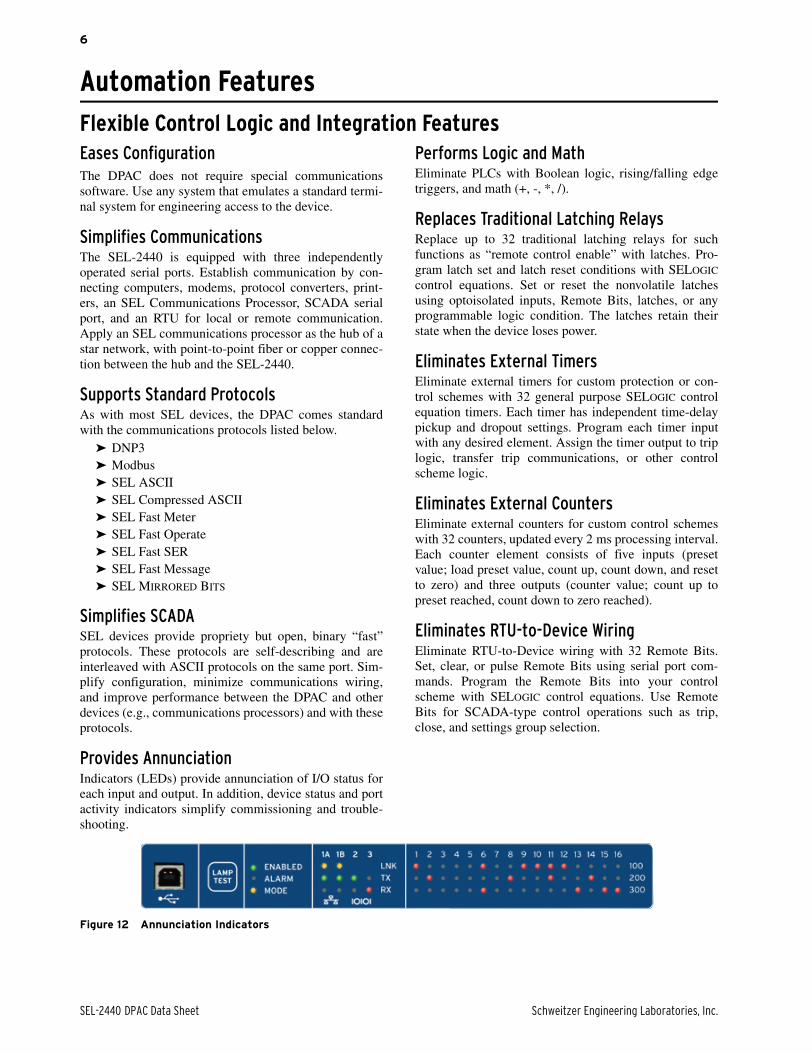
Provides AnnunciationIndicators (LEDs) provide annunciation of I/O status foreach input and output. In addition, device status and portactivity indicators simplify commissioning and trouble-shooting.
Figure 12 Annunciation Indicators
Schweitzer Engineering Laboratories, Inc. SEL-2440 DPAC Data Sheet
7
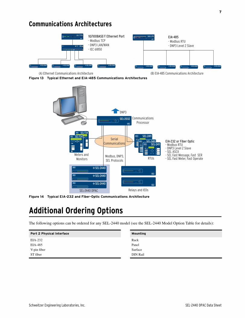
Communications Architectures
Figure 13 Typical Ethernet and EIA-485 Communications Architectures
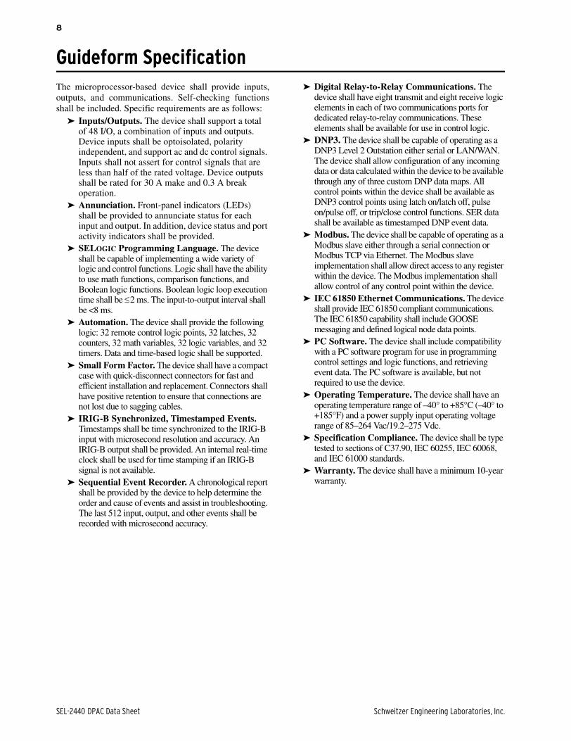
Figure 14 Typical EIA-232 and Fiber-Optic Communications Architecture
Additional Ordering OptionsThe following options can be ordered for any SEL-2440 model (see the SEL-2440 Model Option Table for details):
10/100BASE-T Ethernet Port- Modbus TCP
- DNP3 LAN/WAN
- IEC 61850
EIA-485- Modbus RTU
- DNP3 Level 2 Slave
(A) Ethernet Communications Architecture (B) EIA-485 Communications Architecture
SEL-2440 SEL-2440 SEL-2440 SEL-2440 SEL-2440 SEL-2440 SEL-2440 SEL-2440
SEL-734
SEL-734 SEL-2411
SEL-2411
SEL-2032
SEL-2411
RTUsMeters and
Monitors
SEL-2440 DPAC Relays and IEDs
Communications
Processor
Modbus, DNP3,
SEL Protocols
DNP3
Serial
Communications
SEL-2440
SEL-2440
SEL-2440
EIA-232 or Fiber Optic- Modbus RTU- DNP3 Level 2 Slave- SEL ASCII- SEL Fast Message, Fast SER- SEL Fast Meter, Fast Operate
Port 2 Physical Interface
EIA-232
EIA-485
V-pin fiber
ST fiber
Mounting
Rack
Panel
Surface
DIN Rail
SEL-2440 DPAC Data Sheet Schweitzer Engineering Laboratories, Inc.
8
Guideform SpecificationThe microprocessor-based device shall provide inputs,outputs, and communications. Self-checking functionsshall be included. Specific requirements are as follows:
➤ Inputs/Outputs. The device shall support a total of 48 I/O, a combination of inputs and outputs. Device inputs shall be optoisolated, polarity independent, and support ac and dc control signals. Inputs shall not assert for control signals that are less than half of the rated voltage. Device outputs shall be rated for 30 A make and 0.3 A break operation.
➤ Annunciation. Front-panel indicators (LEDs) shall be provided to annunciate status for each input and output. In addition, device status and port activity indicators shall be provided.
➤ SELOGIC Programming Language. The device shall be capable of implementing a wide variety of logic and control functions. Logic shall have the ability to use math functions, comparison functions, and Boolean logic functions. Boolean logic loop execution time shall be 2 ms. The input-to-output interval shall be <8 ms.
➤ Automation. The device shall provide the following logic: 32 remote control logic points, 32 latches, 32 counters, 32 math variables, 32 logic variables, and 32 timers. Data and time-based logic shall be supported.
➤ Small Form Factor. The device shall have a compact case with quick-disconnect connectors for fast and efficient installation and replacement. Connectors shall have positive retention to ensure that connections are not lost due to sagging cables.
➤ IRIG-B Synchronized, Timestamped Events. Timestamps shall be time synchronized to the IRIG-B input with microsecond resolution and accuracy. An IRIG-B output shall be provided. An internal real-time clock shall be used for time stamping if an IRIG-B signal is not available.
➤ Sequential Event Recorder. A chronological report shall be provided by the device to help determine the order and cause of events and assist in troubleshooting. The last 512 input, output, and other events shall be recorded with microsecond accuracy.
➤ Digital Relay-to-Relay Communications. The device shall have eight transmit and eight receive logic elements in each of two communications ports for dedicated relay-to-relay communications. These elements shall be available for use in control logic.
➤ DNP3. The device shall be capable of operating as a DNP3 Level 2 Outstation either serial or LAN/WAN. The device shall allow configuration of any incoming data or data calculated within the device to be available through any of three custom DNP data maps. All control points within the device shall be available as DNP3 control points using latch on/latch off, pulse on/pulse off, or trip/close control functions. SER data shall be available as timestamped DNP event data.
➤ Modbus. The device shall be capable of operating as a Modbus slave either through a serial connection or Modbus TCP via Ethernet. The Modbus slave implementation shall allow direct access to any register within the device. The Modbus implementation shall allow control of any control point within the device.
➤ IEC 61850 Ethernet Communications. The device shall provide IEC 61850 compliant communications. The IEC 61850 capability shall include GOOSE messaging and defined logical node data points.
➤ PC Software. The device shall include compatibility with a PC software program for use in programming control settings and logic functions, and retrieving event data. The PC software is available, but not required to use the device.
➤ Operating Temperature. The device shall have an operating temperature range of –40° to +85°C (–40° to +185°F) and a power supply input operating voltage range of 85–264 Vac/19.2–275 Vdc.
➤ Specification Compliance. The device shall be type tested to sections of C37.90, IEC 60255, IEC 60068, and IEC 61000 standards.
➤ Warranty. The device shall have a minimum 10-year warranty.
Schweitzer Engineering Laboratories, Inc. SEL-2440 DPAC Data Sheet
9
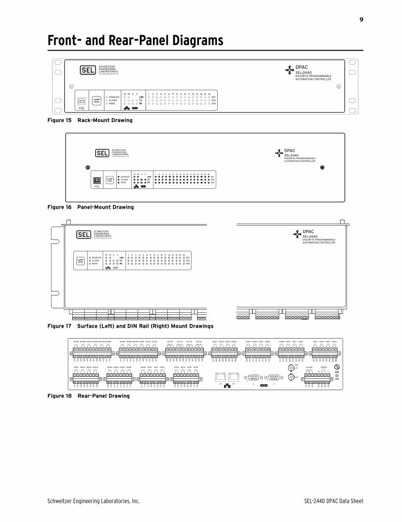
Front- and Rear-Panel Diagrams
Figure 15 Rack-Mount Drawing
Figure 16 Panel-Mount Drawing
Figure 17 Surface (Left) and DIN Rail (Right) Mount Drawings
Figure 18 Rear-Panel Drawing
+ + ——
A09
GND
POWERALARM
Z0
1
Z0
2
Z0
3
Z0
5
Z0
6
Z0
7
Z0
8
A09
GND
OUT
321A 1B
IN
IRIG
C3
1
C3
2
OUT101 OUT102 OUT103 OUT104
IN301 IN302 IN303 IN304 IN305 IN306 IN307 IN308 IN309 IN310 IN311 IN312 IN313 IN314 IN315 IN316
IN201 IN202 IN203 IN204 IN205 IN206 IN207 IN208 IN209 IN210 IN211 IN212 IN213 IN214 IN215 IN216
A0
1
A0
2
A0
3
A0
4
A0
5
A0
6
A0
7
A0
8
A0
9
A10
A1
1
A12
A13
A14
A15
A16
A17
A18
A19
A2
0
A2
1
A2
2
A2
3
A2
4
A2
5
A2
6
A2
7
A2
8
A2
9
A3
0
A3
1
A3
2
A3
3
A3
4
B0
1
B0
2
B0
3
B0
4
B0
5
B0
6
B0
7
B0
8
B0
9
B10
B1
1
B12
B13
B14
B15
B16
B17
B18
B19
B2
0
B2
1
B2
2
B2
3
B2
4
B2
5
B2
6
B2
7
B2
8
B2
9
B3
0
B3
1
B3
2
A3
5
A3
6
OUT105 OUT106 OUT113 OUT114 OUT115 OUT116OUT107 OUT108 OUT109 OUT110 OUT111 OUT112
C0
1
C0
2
C0
3
C0
4
C0
5
C0
6
C0
7
C0
8
C0
9
C10
C1
1
C12
C13
C14
C15
C16
C17
C18
C19
C2
0
C2
1
C2
2
C2
3
C2
4
C2
5
C2
6
C2
7
C2
8
C2
9
C3
0
C3
1
C3
2
SEL-2440 DPAC Data Sheet Schweitzer Engineering Laboratories, Inc.
10
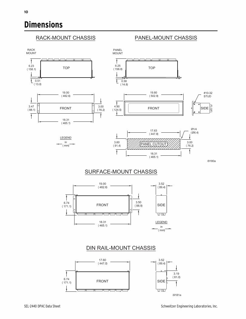
Dimensions
Schweitzer Engineering Laboratories, Inc. SEL-2440 DPAC Data Sheet
11
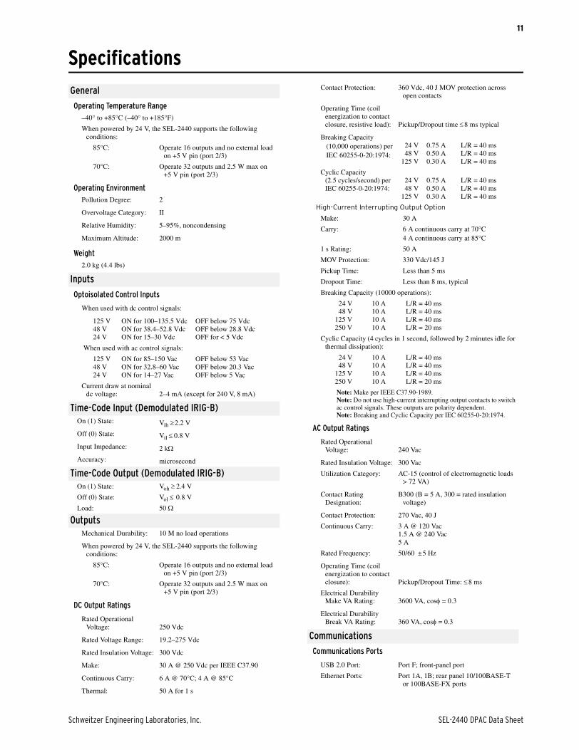
Specifications
General
Operating Temperature Range–40° to +85°C (–40° to +185°F)
When powered by 24 V, the SEL-2440 supports the following conditions:
85°C: Operate 16 outputs and no external load on +5 V pin (port 2/3)
70°C: Operate 32 outputs and 2.5 W max on +5 V pin (port 2/3)
Operating EnvironmentPollution Degree: 2
Overvoltage Category: II
Relative Humidity: 5–95%, noncondensing
Maximum Altitude: 2000 m
Weight2.0 kg (4.4 lbs)
Inputs
Optoisolated Control Inputs
When used with dc control signals:
125 V ON for 100–135.5 Vdc OFF below 75 Vdc48 V ON for 38.4–52.8 Vdc OFF below 28.8 Vdc24 V ON for 15–30 Vdc OFF for < 5 Vdc
When used with ac control signals:
125 V ON for 85–150 Vac OFF below 53 Vac48 V ON for 32.8–60 Vac OFF below 20.3 Vac24 V ON for 14–27 Vac OFF below 5 Vac
Current draw at nominal dc voltage: 2–4 mA (except for 240 V, 8 mA)
Time-Code Input (Demodulated IRIG-B)On (1) State: Vih 2.2 V
Off (0) State: Vil 0.8 V
Input Impedance: 2 k
Accuracy: microsecond
Time-Code Output (Demodulated IRIG-B)On (1) State: Voh 2.4 V
Off (0) State: Vol 0.8 V
Load: 50
OutputsMechanical Durability: 10 M no load operations
When powered by 24 V, the SEL-2440 supports the following conditions:
85°C: Operate 16 outputs and no external load on +5 V pin (port 2/3)
70°C: Operate 32 outputs and 2.5 W max on +5 V pin (port 2/3)
DC Output Ratings
Rated Operational Voltage: 250 Vdc
Rated Voltage Range: 19.2–275 Vdc
Rated Insulation Voltage: 300 Vdc
Make: 30 A @ 250 Vdc per IEEE C37.90
Continuous Carry: 6 A @ 70°C; 4 A @ 85°C
Thermal: 50 A for 1 s
Contact Protection: 360 Vdc, 40 J MOV protection across open contacts
Operating Time (coil energization to contact closure, resistive load): Pickup/Dropout time 8 ms typical
Breaking Capacity(10,000 operations) perIEC 60255-0-20:1974:
24 V 0.75 A L/R = 40 ms48 V 0.50 A L/R = 40 ms
125 V 0.30 A L/R = 40 ms
Cyclic Capacity (2.5 cycles/second) per IEC 60255-0-20:1974:
24 V 0.75 A L/R = 40 ms48 V 0.50 A L/R = 40 ms
125 V 0.30 A L/R = 40 ms
High-Current Interrupting Output Option
Make: 30 A
Carry: 6 A continuous carry at 70°C4 A continuous carry at 85°C
1 s Rating: 50 A
MOV Protection: 330 Vdc/145 J
Pickup Time: Less than 5 ms
Dropout Time: Less than 8 ms, typical
Breaking Capacity (10000 operations):
24 V 10 A L/R = 40 ms48 V 10 A L/R = 40 ms
125 V 10 A L/R = 40 ms250 V 10 A L/R = 20 ms
Cyclic Capacity (4 cycles in 1 second, followed by 2 minutes idle for thermal dissipation):
24 V 10 A L/R = 40 ms48 V 10 A L/R = 40 ms
125 V 10 A L/R = 40 ms250 V 10 A L/R = 20 ms
Note: Make per IEEE C37.90-1989.Note: Do not use high-current interrupting output contacts to switch ac control signals. These outputs are polarity dependent.Note: Breaking and Cyclic Capacity per IEC 60255-0-20:1974.
AC Output Ratings
Rated Operational Voltage: 240 Vac
Rated Insulation Voltage: 300 Vac
Utilization Category: AC-15 (control of electromagnetic loads > 72 VA)
Contact Rating Designation:
B300 (B = 5 A, 300 = rated insulation voltage)
Contact Protection: 270 Vac, 40 J
Continuous Carry: 3 A @ 120 Vac1.5 A @ 240 Vac5 A
Rated Frequency: 50/60 ±5 Hz
Operating Time (coil energization to contact closure): Pickup/Dropout Time: 8 ms
Electrical Durability Make VA Rating: 3600 VA, cos = 0.3
Electrical Durability Break VA Rating: 360 VA, cos = 0.3
Communications
Communications Ports
USB 2.0 Port: Port F; front-panel port
Ethernet Ports: Port 1A, 1B; rear panel 10/100BASE-T or 100BASE-FX ports
SEL-2440 DPAC Data Sheet Schweitzer Engineering Laboratories, Inc.
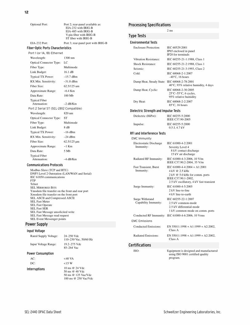
12
Optional Port: Port 2; rear-panel available as:EIA-232 with IRIG-BEIA-485 with IRIG-BV-pin fiber with IRIG-BST fiber with IRIG-B
EIA-232 Port: Port 3; rear-panel port with IRIG-B
Fiber-Optic Ports CharacteristicsPort 1 (or 1A, 1B) Ethernet
Wavelength: 1300 nm
Optical Connector Type: LC
Fiber Type: Multimode
Link Budget: 16.1 dB
Typical TX Power: –15.7 dBm
RX Min. Sensitivity: –31.8 dBm
Fiber Size: 62.5/125 um
Approximate Range: ~6.4 Km
Data Rate: 100 Mb
Typical Fiber Attenuation: –2 dB/Km
Port 2 Serial ST (SEL-2812 Compatible)
Wavelength: 820 nm
Optical Connector Type: ST
Fiber Type: Multimode
Link Budget: 8 dB
Typical TX Power: –16 dBm
RX Min. Sensitivity: –24 dBm
Fiber Size: 62.5/125 µm
Approximate Range: ~1 Km
Data Rate: 5 Mb
Typical Fiber Attenuation: –4 dB/Km
Communications ProtocolsModbus Slave (TCP and RTU)DNP3 Level 2 Outstation (LAN/WAN and Serial)IEC 61850 communicationsFTPTelnetSEL MIRRORED BITS
Ymodem file transfer on the front and rear portXmodem file transfer on the front portSEL ASCII and Compressed ASCIISEL Fast MeterSEL Fast OperateSEL Fast SERSEL Fast Message unsolicited writeSEL Fast Message read requestSEL Event Messenger points
Power Supply
Input VoltageRated Supply Voltage: 24–250 Vdc
110–230 Vac, 50/60 Hz
Input Voltage Range: 19.2–275 Vdc85–264 Vac
Power ConsumptionAC: <40 VA
DC: <15 W
Interruptions 10 ms @ 24 Vdc50 ms @ 48 Vdc50 ms @ 125 Vac/Vdc100 ms @ 250 Vac/Vdc
Processing Specifications2 ms
Type Tests
Environmental TestsEnclosure Protection: IEC 60529:2001
IP65 enclosed in panelIP20 for terminals
Vibration Resistance: IEC 60255-21-1:1988, Class 1
Shock Resistance: IEC 60255-21-2:1988, Class 1
Seismic: IEC 60255-21-3:1993, Class 2
Cold: IEC 60068-2-1:2007–40°C, 16 hours
Damp Heat, Steady State: IEC 60068-2-78:200140°C, 93% relative humidity, 4 days
Damp Heat, Cyclic: IEC 60068-2-30:200525°C–55°C, 6 cycles, 95% relative humidity
Dry Heat: IEC 60068-2-2:200785°C, 16 hours
Dielectric Strength and Impulse TestsDielectric (HiPot): IEC 60255-5:2000
IEEE C37.90-2005
Impulse: IEC 60255-5:20000.5 J, 4.7 kV
RFI and Interference TestsEMC Immunity
Electrostatic Discharge Immunity:
IEC 61000-4-2:2001Severity Level 4
8 kV contact discharge15 kV air discharge
Radiated RF Immunity: IEC 61000-4-3:2006, 10 V/mIEEE C37.90.2-2004, 35 V/m
Fast Transient, Burst Immunity:
IEC 61000-4-4:2004 + A1:20014 kV @ 2.5 kHz2 kV @ 5.0 kHz for comm. ports
IEEE C37.90.1-2002, 2.5 kV oscillatory, 4 kV fast transient
Surge Immunity: IEC 61000-4-5:20052 kV line-to-line4 kV line-to-earth
Surge Withstand Capability Immunity:
IEC 60255-22-1:20072.5 kV common-mode2.5 kV differential-mode1 kV common-mode on comm. ports
Conducted RF Immunity: IEC 61000-4-6:2006, 10 Vrms
EMC Emissions
Conducted Emissions: EN 55011:1998 + A1:1999 + A2:2002, Class A
Radiated Emissions: EN 55011:1998 + A1:1999 + A2:2002, Class A
CertificationsISO: Equipment is designed and manufactured
using ISO 9001 certified quality program.

Schweitzer Engineering Laboratories, Inc. SEL-2440 DPAC Data Sheet
13
Notes

SEL-2440 DPAC Data Sheet Schweitzer Engineering Laboratories, Inc.
14
Notes

Schweitzer Engineering Laboratories, Inc. SEL-2440 DPAC Data Sheet
15
Notes

16
© 2008–2009 by Schweitzer Engineering Laboratories, Inc. All rights reserved.
All brand or product names appearing in this document are the trademark or registered trade-mark of their respective holders. No SEL trademarks may be used without written permission.SEL products appearing in this document may be covered by US and Foreign patents.
Schweitzer Engineering Laboratories, Inc. reserves all rights and benefits afforded under fed-eral and international copyright and patent laws in its products, including without limitationsoftware, firmware, and documentation.
The information in this document is provided for informational use only and is subject tochange without notice. Schweitzer Engineering Laboratories, Inc. has approved only theEnglish language document.
This product is covered by the standard SEL 10-year warranty. For warranty details, visitwww.selinc.com or contact your customer service representative. *PDS2440-01*
SCHWEITZER ENGINEERING LABORATORIES2350 NE Hopkins Court • Pullman, WA 99163-5603 USA
Phone: +1.509.332.1890 • Fax: +1.509.332.7990
Internet: www.selinc.com • E-mail: [email protected]
SEL-2440 DPAC Data Sheet Date Code 20091116