24 MW HFO Plant-Containerized-MT0120 - WikiLeaks MW HFO Plan.pdf · 24 MW MAN POWER PLANT...
13
24 MW MAN POWER PLANT (Containerized), 50 Hz, 11kV Consisting of Six (6) units of MAN 18V28/32S, 4 MW each Benefits to Modular Design 24 MW containerized HFO Power Plant. Uses straight forward foundations for Generator sets. Balance of the plant has been desig ned and inst alled into standard shipping containers for easy transport. The modular design minimizes set up time and cost on site. Can be put into operation 4 months from arrival to site. Basic Description MAN Diesel (HFO) 18V28/32 Containerized Generator Sets Siemens Control and Instrumentation Alfa Laval fuel processing equipment Chubb fire protection
Transcript of 24 MW HFO Plant-Containerized-MT0120 - WikiLeaks MW HFO Plan.pdf · 24 MW MAN POWER PLANT...

24 MW MAN POWER PLANT (Containerized), 50 Hz, 11kV Consisting of Six (6) units of MAN 18V28/32S, 4 MW each
Benefits to Modular Design 24 MW containerized HFO Power Plant. Uses straight forward foundations for Generator sets. Balance of the plant has been designed and inst alled into standard shipping containers for easy
transport. The modular design minimizes set up time and cost on site. Can be put into operation 4 months from arrival to site.
Basic Description MAN Diesel (HFO) 18V28/32 Containerized Generator Sets Siemens Control and Instrumentation Alfa Laval fuel processing equipment Chubb fire protection
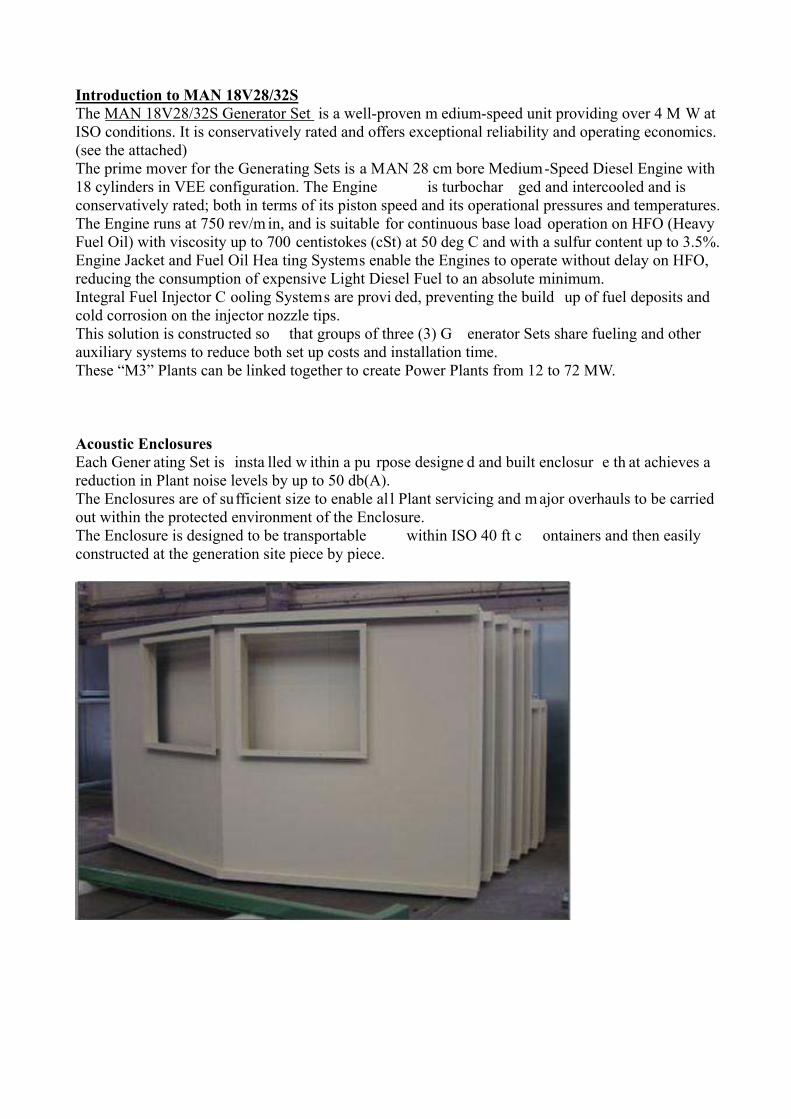
Introduction to MAN 18V28/32S The MAN 18V28/32S Generator Set is a well-proven m edium-speed unit providing over 4 M W at ISO conditions. It is conservatively rated and offers exceptional reliability and operating economics. (see the attached) The prime mover for the Generating Sets is a MAN 28 cm bore Medium-Speed Diesel Engine with 18 cylinders in VEE configuration. The Engine is turbochar ged and intercooled and is conservatively rated; both in terms of its piston speed and its operational pressures and temperatures. The Engine runs at 750 rev/m in, and is suitable for continuous base load operation on HFO (Heavy Fuel Oil) with viscosity up to 700 centistokes (cSt) at 50 deg C and with a sulfur content up to 3.5%. Engine Jacket and Fuel Oil Hea ting Systems enable the Engines to operate without delay on HFO, reducing the consumption of expensive Light Diesel Fuel to an absolute minimum. Integral Fuel Injector C ooling Systems are provi ded, preventing the build up of fuel deposits and cold corrosion on the injector nozzle tips. This solution is constructed so that groups of three (3) G enerator Sets share fueling and other auxiliary systems to reduce both set up costs and installation time. These “M3” Plants can be linked together to create Power Plants from 12 to 72 MW. Acoustic Enclosures Each Gener ating Set is insta lled w ithin a pu rpose designe d and built enclosur e th at achieves a reduction in Plant noise levels by up to 50 db(A). The Enclosures are of sufficient size to enable al l Plant servicing and m ajor overhauls to be carried out within the protected environment of the Enclosure. The Enclosure is designed to be transportable within ISO 40 ft c ontainers and then easily constructed at the generation site piece by piece.
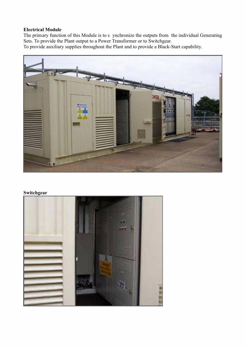
Electrical Module The primary function of this Module is to s ynchronize the outputs from the individual Generating Sets. To provide the Plant output to a Power Transformer or to Switchgear. To provide auxiliary supplies throughout the Plant and to provide a Black-Start capability.
Switchgear
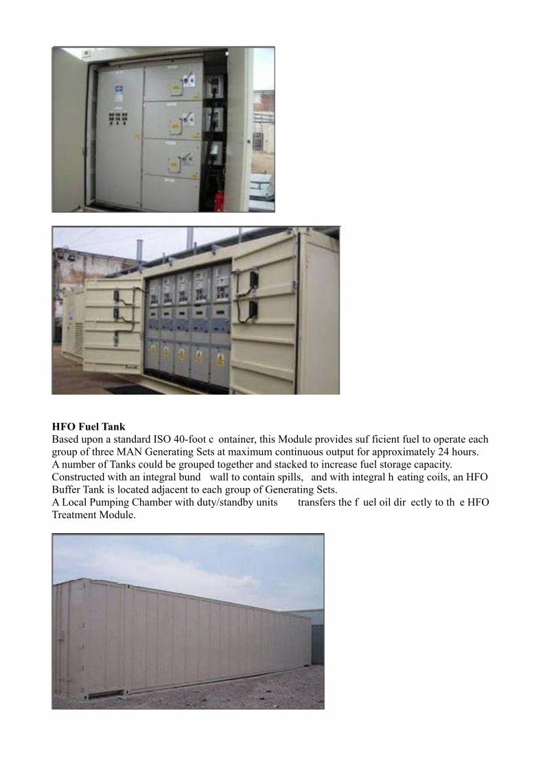
HFO Fuel Tank Based upon a standard ISO 40-foot c ontainer, this Module provides suf ficient fuel to operate each group of three MAN Generating Sets at maximum continuous output for approximately 24 hours. A number of Tanks could be grouped together and stacked to increase fuel storage capacity. Constructed with an integral bund wall to contain spills, and with integral h eating coils, an HFO Buffer Tank is located adjacent to each group of Generating Sets. A Local Pumping Chamber with duty/standby units transfers the f uel oil dir ectly to th e HFO Treatment Module.
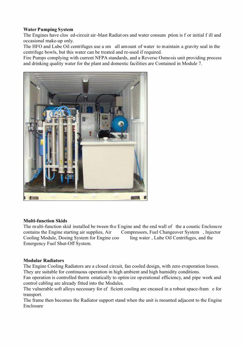
Water Pumping System The Engines have clos ed-circuit air -blast Radiat ors and water consum ption is f or initial f ill and occasional make-up only. The HFO and Lube Oil centrifuges use a sm all amount of water to maintain a gravity seal in the centrifuge bowls, but this water can be treated and re-used if required. Fire Pumps complying with current NFPA standards, and a Reverse Osmosis unit providing process and drinking quality water for the plant and domestic facilities are Contained in Module 7.
Multi-function Skids The multi-function skid installed be tween the Engine and the end wall of the a coustic Enclosu re contains the Engine starting air supplies, Air Compressors, Fuel Changeover System , Injector Cooling Module, Dosing System for Engine coo ling water , Lube Oil Centrifuges, and the Emergency Fuel Shut-Off System. Modular Radiators The Engine Cooling Radiators are a closed circuit, fan cooled design, with zero evaporation losses. They are suitable for continuous operation in high ambient and high humidity conditions. Fan operation is controlled therm ostatically to optim ize operational efficiency, and pipe work and control cabling are already fitted into the Modules. The vulnerable soft alloys necessary for ef ficient cooling are encased in a robust space-fram e for transport. The frame then becomes the Radiator support stand when the unit is mounted adjacent to the Engine Enclosure

HFO Module Based upon a standard ISO 40-foot container , th is Module will continuously treat HFO with viscosities ranging up to 380 cen tistokes at 50 deg C, and supply it to each group of three MAN Generating Sets. The Module Equipm ent com prises the latest fuel treatm ent technology , including Alfa Laval duty/standby centrifuge filters and fuel forwarding units. Conservatively rated transfer a nd circulating Pumps, pre and pos t centrifuge Treatment Tanks, and Fuel Oil Heating Units are an integral part of this Module. The Module design is adequate for the treatment of HFO at ambient temperatures down to 10 deg C using either electric heaters or high temperature hot water produced by Exhaust Gas Economizers. Individually pumped ring mains supply the treated HFO to the MAN Generating Sets. An individual Generating Set can be taken out of service for scheduled m aintenance without impacting upon the security or reliability of the remaining running units.
Alfa Laval Centrifuges
Fuel conditioning module
Module HFO Pump
ISO 40 ft Container
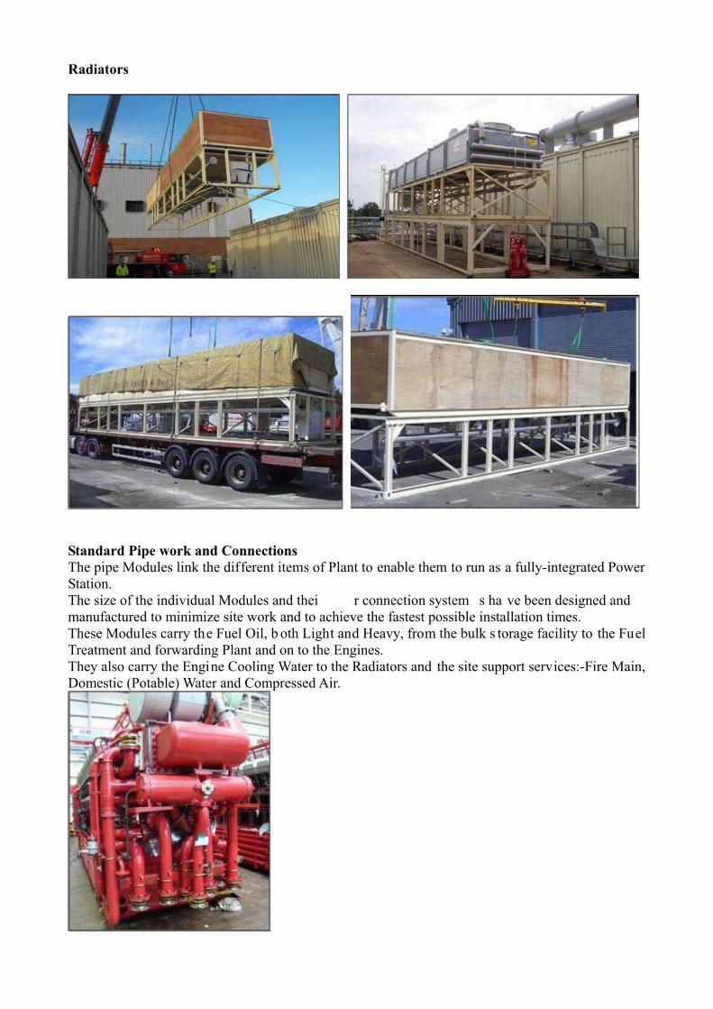
Radiators
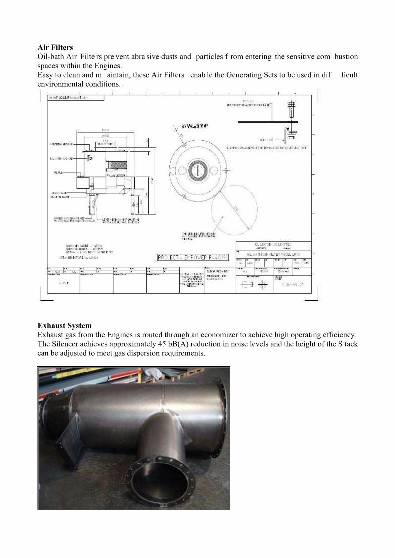
Standard Pipe work and Connections The pipe Modules link the different items of Plant to enable them to run as a fully-integrated Power Station. The size of the individual Modules and thei r connection system s ha ve been designed and manufactured to minimize site work and to achieve the fastest possible installation times. These Modules carry the Fuel Oil, b oth Light and Heavy, from the bulk s torage facility to the Fuel Treatment and forwarding Plant and on to the Engines. They also carry the Engine Cooling Water to the Radiators and the site support services:-Fire Main, Domestic (Potable) Water and Compressed Air.
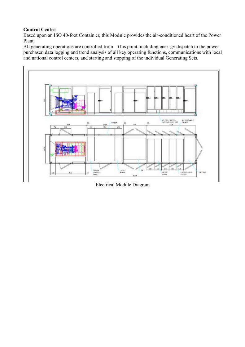
Air Filters Oil-bath Air Filte rs pre vent abra sive dusts and particles f rom entering the sensitive com bustion spaces within the Engines. Easy to clean and m aintain, these Air Filters enab le the Generating Sets to be used in dif ficult environmental conditions.
Exhaust System Exhaust gas from the Engines is routed through an economizer to achieve high operating efficiency. The Silencer achieves approximately 45 bB(A) reduction in noise levels and the height of the S tack can be adjusted to meet gas dispersion requirements.
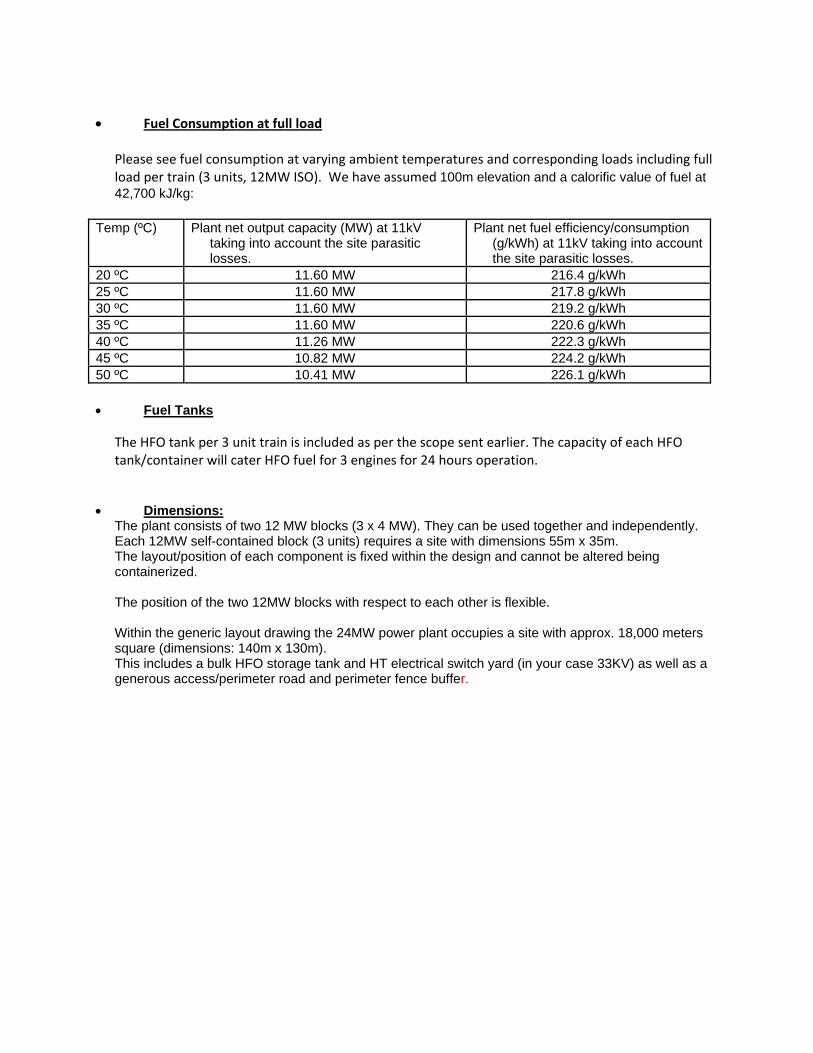
Control Centre Based upon an ISO 40-foot Contain er, this Module provides the air-conditioned heart of the Power Plant. All generating operations are controlled from t his point, including ener gy dispatch to the power purchaser, data logging and trend analysis of all key operating functions, communications with local and national control centers, and starting and stopping of the individual Generating Sets.
Electrical Module Diagram

Other Technical Information The offered Six (6) units of MAN 18V28/32S are brand new and manufactured in year 2009. All units were never used for any commercial operation and are with full OEM warranty. Type and make of Control and Instrumentation.
Control system was designed by Regulateurs Europa and set of Siemens make SCADA control equipment.
Type and make of the components of the switchgear and circuit breakers
Siemens Simoprime 11KV Switchgear and Circuit Breakers. Output Voltage of the plant
Generator voltage is 11KV Step-up transformers voltage is 11/33KV.
Transformers and output power
Two 11/33KV step-up Transformers. Each Transformer rating is 16MVA Make of Step-up Transformers is Winder Electricals.
One Containerized 33KV Switchgear with two incoming feeders (each 1250A) from two 11/33KV Transformers and 6 outgoing feeders of 1250A each. All 6 circuit breakers will have Copper bus. Besides that it will also include 2 Transformer Protection Panels, Grid Protection Panel, Synchronizing Panel, Instrumentation and HT Cabling (Copper). We have considered 10 meters length each between Transformers and 33KV Switchgear.
Scope of Supply plus engineering and supervision.
The plant to be supplied is complete and containerized. It will be supplied with the complete design and engineering together with the execution drawings for installation. A local contractor will take care of the civil work, installation and commissioning, as per the design and engineering provided.
Warranty All six units are under full warranty (1 year) from MAN.
Year of Manufacture
The year of manufacture of 6 MAN engines and Balance of Plant is 2008/2009.
Fuel Consumption at full load
Please see fuel consumption at varying ambient temperatures and corresponding loads including full load per train (3 units, 12MW ISO). We have assumed 100m elevation and a calorific value of fuel at 42,700 kJ/kg:
Temp (ºC) Plant net output capacity (MW) at 11kV
taking into account the site parasitic losses.
Plant net fuel efficiency/consumption (g/kWh) at 11kV taking into account the site parasitic losses.
20 ºC 11.60 MW 216.4 g/kWh 25 ºC 11.60 MW 217.8 g/kWh 30 ºC 11.60 MW 219.2 g/kWh 35 ºC 11.60 MW 220.6 g/kWh 40 ºC 11.26 MW 222.3 g/kWh 45 ºC 10.82 MW 224.2 g/kWh 50 ºC 10.41 MW 226.1 g/kWh Fuel Tanks
The HFO tank per 3 unit train is included as per the scope sent earlier. The capacity of each HFO tank/container will cater HFO fuel for 3 engines for 24 hours operation.
Dimensions:
The plant consists of two 12 MW blocks (3 x 4 MW). They can be used together and independently. Each 12MW self-contained block (3 units) requires a site with dimensions 55m x 35m. The layout/position of each component is fixed within the design and cannot be altered being containerized.
The position of the two 12MW blocks with respect to each other is flexible.
Within the generic layout drawing the 24MW power plant occupies a site with approx. 18,000 meters square (dimensions: 140m x 130m). This includes a bulk HFO storage tank and HT electrical switch yard (in your case 33KV) as well as a generous access/perimeter road and perimeter fence buffer.

ERECTION & COMMISSIONING
Technical Description of Erection All items and systems indicated below including piping, cabling and accessories (containerized) will be erected and prepared for commissioning.
6 units of MAN 18V28/32S HFO based Containerized Gensets Siemens Controls and Instrumentation Alfa Laval Fuel processing equipment Chubb Fire protection Tank Farm house including HFP and Diesel Tanks Water Pumping Station Modular Radiators HFO Modules Pipe work and connections Control center Control panels Step-up Transformers (11/33 kV) 33kV HT Switchyard Cables, wiring, etc. If required, Flushing of oil, water, fuel lines Workers of erection team will take all safety precautions during their work (safety belts, glass,
handgloves, barret, etc.) Engineering team will support engineering work for any change or modifications.
Technical Description of Commissioning All commissioning work will be done by erection team and their qualified engineers.
Checking of all power plant equipment, piping, cabling Checking of main engines, generators, etc. Valve clearance adjustments Alignment check Adjustment of speed governors, voltage regulators, transformers, synchronizing, load shedding,
etc. Short running of electrical motors, pumps for correct running Simulation of all alarm points Simulation of all shut-down points Re-adjustment or re-calibration of sensing elements Inspection of HFO, Lube oil, compressed air, water, etc. lines Flushing of pipes, if required Turbochargers inspection Getting into operation of all auxiliaries Running-in process for engines Booster module viscosity/temperature/pressure adjustment Getting into operation separators, filters, pumps, preheating modules, compressors, etc. Getting into operation of complete power plant and delivery to owner Civil work (whatever required), ground leveling, etc. will be carried out by erection team
Responsibilities of Owner for Erection and Commissioning
Supply of compressed air

Supply of power and lighting Supply of HFO, Diesel, Lube oil Supply of oxygen/acetilen for welding Supply of available crane facility during all erection time Accommodation and food for all erection and commissioning workers/engineers at site Supply of security, in case of any danger providing fastest and safest way to leave the site Preheater for engine oil by steam or electricity Treated water supply for engine cooling water, separators Cleaning of equipments and engines, engine components, etc. All statutory clearances, permits, licenses, etc.