2.4 GHz WIRELESS COLOR SECURITY SYSTEM WITH · PDF file2.4 GHz WIRELESS COLOR SECURITY SYSTEM...
17
MODEL: SG6352 2.4 GHz WIRELESS COLOR SECURITY SYSTEM WITH WEATHER RESISTANT* CAMERA Instruction Manual www.lorexcctv.com Copyright © 2005 Strategic Vista International Inc English Version 1.0 Before operating the system, please read this manual thoroughly and retain it for future reference. This product broadcasts over public airwaves and its video and audio signals may be intercepted without your consent. * IP44 rated for Indoor and Outdoor use. Not recommended for direct exposure to water, rain or snow.
-
Upload
dinhkhuong -
Category
Documents
-
view
220 -
download
4
Transcript of 2.4 GHz WIRELESS COLOR SECURITY SYSTEM WITH · PDF file2.4 GHz WIRELESS COLOR SECURITY SYSTEM...

MODEL: SG6352
2.4 GHz WIRELESS COLOR SECURITY SYSTEM WITH
WEATHER RESISTANT* CAMERA
Instruction Manual
www.lorexcctv.comCopyright © 2005 Strategic Vista International Inc
English Version 1.0
Before operating the system, please read this manualthoroughly and retain it for future reference.
This product broadcasts over public airwaves and its video and audio signals may be intercepted without your consent.
* IP44 rated for Indoor and Outdoor use. Not recommended for direct exposure to water, rain or snow.
Explanation of two SymbolsThe lightning flash with arrowhead symbol, within anequilateral triangle, is intended to alert the user to thepresence of uninsulated "dangerous voltage“ within theproduct's enclosure that may be of sufficient magnitude toconstitute a risk of electric shock to persons.
The exclamation point within an equilateral triangle isintended to alert the user to the presence of importantoperating and maintenance(servicing) instructions inthe literature accompanying the appliance.
THE GRAPHIC SYMBOLS WITH SUPPLEMENTAL MARKING ARE ONTHE BOTTOM OF THE SYSTEM.
!
WARNING: To prevent fire or shock hazard, do not expose this unit torain, water, or wet locations. Do not insert any metallic object through the ventilation grills.
FCC CLASS B NOTICENote:This equipment has been tested and found to comply with the limits For a Class B digital device, pursuant to Part 15 of the FCC Rules. These limits are designed to provide reasonable protection against harmful interference in a residential installation. This equipment generates, uses and can radiate radio frequency energy and, if not installed and used in accordance with the instruction, may cause harmful interference to radio communications. However, there is no guarantee that interference will not occur in a particular installation. If this equipment does cause harmful interference to radio or television reception, (which can be determined by turning the equipment off and on), the user is encouraged to try to correct the interference by one or more of the following measures:
CAUTIONRISK OF ELECTRIC SHOCK. DO NOT OPEN.
CAUTION: TO REDUCE THE RISK OF ELECTRIC SHOCK, DO NOT REMOVE COVER (OR BACK). NO USER-SERVICEABLE PARTS INSIDE. REFER
SERVICING TO QUALIFIED SERVICE PERSONNEL.
!
• Reorient or relocate the receiving antenna• Connect the equipment into an outlet on a circuit different from that to whichother devices may be connected.
• Consult the dealer or an experienced radio or television technician for help.
i

SAFETY INSTRUCTIONSIMPORTANT SAFEGUARDSAll the safety and operating instructions should be read before the system is operated, and retained for future reference.
1. HEED WARNINGS - All warnings on the appliance and in the operatinginstructions should be adhered to.
2. FOLLOW INSTRUCTIONS - All operating instructions should befollowed.
3. WATER AND MOISTURE - Do not use this video product near water –for example, a bath tub, wash bowl, kitchen sink, laundry tub orswimming pool, or in a wet basement.
4. POWER SOURCES - This product should be operated only from the typeof power source indicated on the marking label.
5. OVERLOADING - Do not overload outlets and extension cords, whichcan result in a risk of fire or electric shock.
6. SERVICING - Do not attempt to service this product yourself. Opening orremoving covers may expose you to dangerous voltage or other hazards.Refer all servicing or repairs to qualified service personnel.
7. DAMAGE REQUIRING SERVICE - Unplug this product from the walloutlet and refer servicing or repairs to qualified service personnel underthe following conditions:
a. When the power supply cord or plug is damaged.b. If liquid has been spilled or objects have fallen into the product.c. If the product has been exposed to rain or water.d. If the product does not operate normally by following the operating
instructions. Adjust only those controls that are covered by theoperating instructions.
e. If the product has been dropped or the cabinet has been damaged.f. When the product exhibits a distinct change in performance.
8. REPLACEMENT PARTS - When replacement parts are required, besure the service technician has used replacement parts that arespecified by the manufacturer or have the same characteristics as theoriginal part. Unauthorized substitutions may result in fire, electricshock, or other hazards.
9. SAFETY CHECK - Upon completion of any service or repairs to thisvideo product, ask the service technician to perform safety checks todetermine if the video product is in proper operating condition.
10. An appliance and cart combination should be moved with care.Do not place this equipment on an unstable cart, stand, or table.The
equipment may fall, causing serious injury to a child or adult, andserious damage to the equipment. Wall or shelf mounting shouldfollow the manufacturer's instructions and should be done with a mounting kit approved by the manufacturer.
ii

TABLE OF CONTENTS PAGE
iii
INTRODUCTION & FEATURES………………………………………
SYSTEM INCLUDES…………………………………………………..
CONTROLS AND FUNCTIONSWireless Camera….......…….......….……………………..……...Wireless Receiver...……..............................……….……...……
INSTALLATION OF WIRELESS CAMERA………………………….
INSTALLATION OF WIRELESS RECEIVEROperation with TV (Using RCA Cables)......……………….….... Operation with TV (Using Coaxial Cable) ..............…..……......
SYSTEM OPERATIONMultiple Cameras / Auto Scanning…………………………………Auto/Manual Options / Selectable Settings………………………
TROUBLE SHOOTING ..............................................………..…...
TECHNICAL SPECIFICATIONS ....................................................
CARE & MAINTENANCE……………………………..……………….
1
2
34
5
67
89
10
11
12
INTRODUCTION:
Thank you for purchasing the 2.4 GHz Wireless Color Camera & Receiver System. This system turns your TV into a Video Security System, providing instant protection in your home or office. Avoid the hassle of running wires. This system is easy to install and operate for immediate applications.
The system is capable of connecting up to 4 cameras (additional cameras sold separately) with the option to automatically scan between locations.
To learn more about this 2.4GHz Wireless Camera & Receiver System and our complete range of CCTV products, please visit our website at:
www.lorexcctv.com
FEATURES:• Turns your TV into a Video Security System• Camera rated IP44* for Indoor and Outdoor use• Listen-in audio• 300 ft Wireless Transmission (open space)• 2.4 GHz Wireless Transmission• Crystal clear Video and Stereo audio• 4 Channel Wireless System • Record picture to any standard VCR• Automatic IR illumination provides B&W video images in low light conditions**• Bonus clip-on stand included for quick mounting application
1
* IP44 rated for Indoor and Outdoor use. Not recommended for direct exposure to water, rain or snow.** IR illumination range of 6ft. under ideal conditions. Objects at or beyond this range may be partially or completely obscured, depending on the camera application.

SYSTEM INCLUDES:
1 - 2.4 GHz Color Wireless Camera
Owner’s Manual
Also includes:2 – 9V DC Adapters1 – RCA Audio/Video Cable1 – Coaxial Cable
2
1 - 2.4 GHz Wireless Receiver
1 - Clip-on Stand 1 - Wall Mounting Bracket

CONTROLS & FUNCTIONS
1. Microphone – Built-in condenser microphone provides listen-in audiocapability from camera to monitor
2. Lens – B&W CMOS Image Sensor
3. 6 Infrared LED’s – Enhances the picture quality in low light conditions*
4. Channel Selector/Power Button – Selects channels 1-4. Holding this button for 3 seconds turns the power ON/OFF (by default the camera is ON).
5. Bracket – Plastic bracket connects to camera for mounting to walls,ceilings or table
6. DC IN Jack – Connects to the 9V DC adapter.
7. Sunshade Visor – Protects camera from the elements and blocks the camera from the direct glare of the sun.
8. LED Channel Indicator – Shows the channel (1-4) that the camera is set to.
Front/Side View
3
* IR illumination range of 6ft. under ideal conditions. Objects at or beyond this range may be partially or completely obscured, depending on the camera application.
23
4
5
7
6
1
6
8
WIRELESS CAMERA
WIRELESS RECEIVERREAR VIEW
BOTTOM VIEW
9 10
5 6 7 8
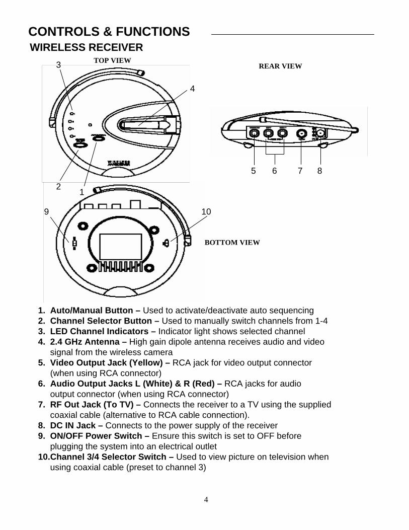
1. Auto/Manual Button – Used to activate/deactivate auto sequencing2. Channel Selector Button – Used to manually switch channels from 1-43. LED Channel Indicators – Indicator light shows selected channel4. 2.4 GHz Antenna – High gain dipole antenna receives audio and video
signal from the wireless camera 5. Video Output Jack (Yellow) – RCA jack for video output connector
(when using RCA connector)6. Audio Output Jacks L (White) & R (Red) – RCA jacks for audio
output connector (when using RCA connector)7. RF Out Jack (To TV) – Connects the receiver to a TV using the supplied
coaxial cable (alternative to RCA cable connection).8. DC IN Jack – Connects to the power supply of the receiver9. ON/OFF Power Switch – Ensure this switch is set to OFF before
plugging the system into an electrical outlet10.Channel 3/4 Selector Switch – Used to view picture on television when
using coaxial cable (preset to channel 3)
CONTROLS & FUNCTIONS
TOP VIEW3
2
4
1
4
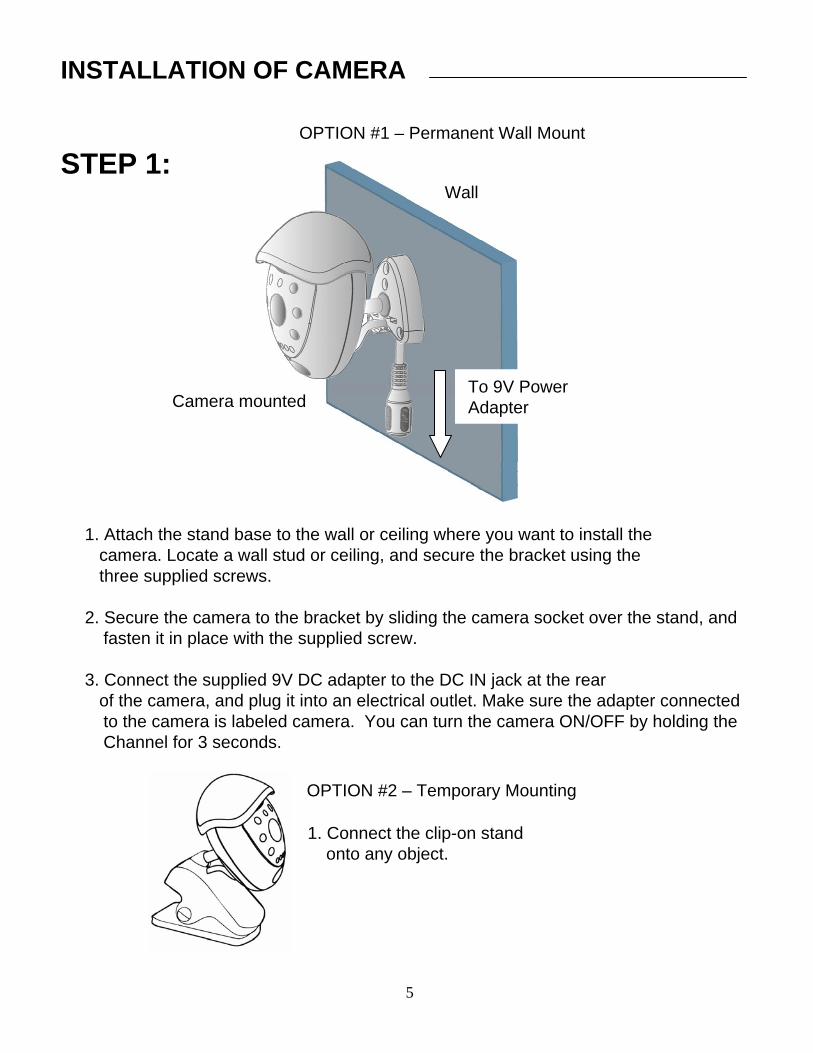
1. Attach the stand base to the wall or ceiling where you want to install thecamera. Locate a wall stud or ceiling, and secure the bracket using thethree supplied screws.
2. Secure the camera to the bracket by sliding the camera socket over the stand, and fasten it in place with the supplied screw.
3. Connect the supplied 9V DC adapter to the DC IN jack at the rearof the camera, and plug it into an electrical outlet. Make sure the adapter connected to the camera is labeled camera. You can turn the camera ON/OFF by holding the Channel for 3 seconds.
5
To 9V Power AdapterCamera mounted
Wall
OPTION #1 – Permanent Wall Mount
OPTION #2 – Temporary Mounting
1. Connect the clip-on stand onto any object.
STEP 1:
INSTALLATION OF CAMERA
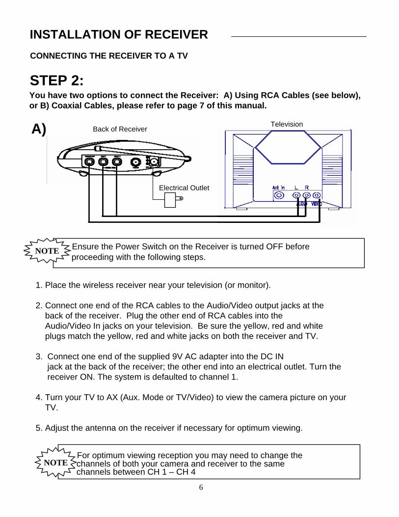
CONNECTING THE RECEIVER TO A TV
INSTALLATION OF RECEIVER
STEP 2:
Ensure the Power Switch on the Receiver is turned OFF before proceeding with the following steps.
NOTE
1. Place the wireless receiver near your television (or monitor).
2. Connect one end of the RCA cables to the Audio/Video output jacks at theback of the receiver. Plug the other end of RCA cables into theAudio/Video In jacks on your television. Be sure the yellow, red and whiteplugs match the yellow, red and white jacks on both the receiver and TV.
3. Connect one end of the supplied 9V AC adapter into the DC IN jack at the back of the receiver; the other end into an electrical outlet. Turn the receiver ON. The system is defaulted to channel 1.
4. Turn your TV to AX (Aux. Mode or TV/Video) to view the camera picture on yourTV.
5. Adjust the antenna on the receiver if necessary for optimum viewing.
For optimum viewing reception you may need to change the channels of both your camera and receiver to the same channels between CH 1 – CH 4
NOTE
You have two options to connect the Receiver: A) Using RCA Cables (see below), or B) Coaxial Cables, please refer to page 7 of this manual.
Back of ReceiverTelevision
Electrical Outlet
A)
6
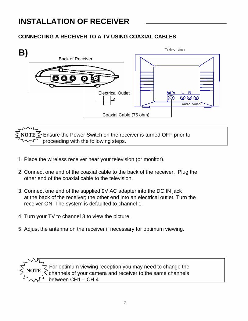
CONNECTING A RECEIVER TO A TV USING COAXIAL CABLES
INSTALLATION OF RECEIVER
B)Back of Receiver
Television
Electrical Outlet
Coaxial Cable (75 ohm)
Ensure the Power Switch on the receiver is turned OFF prior to proceeding with the following steps.
NOTE
1. Place the wireless receiver near your television (or monitor).
2. Connect one end of the coaxial cable to the back of the receiver. Plug theother end of the coaxial cable to the television.
3. Connect one end of the supplied 9V AC adapter into the DC IN jackat the back of the receiver; the other end into an electrical outlet. Turn thereceiver ON. The system is defaulted to channel 1.
4. Turn your TV to channel 3 to view the picture.
5. Adjust the antenna on the receiver if necessary for optimum viewing.
For optimum viewing reception you may need to change thechannels of your camera and receiver to the same channelsbetween CH1 – CH 4
NOTE
Audio Video
7
SYSTEM OPERATION
CONNECTING MORE CAMERAS TO YOUR SYSTEM (MAX. OF 4)
When connecting additional cameras to this system, ensure the camera is set to a different channel. Use the Channel Selector button to navigate between channels.
AUTO SCANNING - WHEN UTILIZING MORE THAN 1 CAMERA
The video security system provides you with the option to automatically scan/switch between four camera locations. If you are utilizing less than four cameras, you can also set the system to scan only within two or three locations.
Setting Auto Scan to 2 or 3 camera locations:
1. Press and hold the Auto/Manual button for more than 2 seconds. All four LED lights on the front of the receiver will turn ON. Releasing the Auto/Manual button to remain in the four channel switching option.
2. Continue to press and hold the Auto/Manual button. The Channel 4 LEDbutton will turn off. The system is now set to scan between three cameralocations (Channel 1-3).
3. Continue to press and hold the Auto/Manual button. The Channel 3 LEDbutton will now be turned off. The system is now set to scan between twocamera locations (Channel 1-2).
4. Continue to press and hold the Auto/Manual button to return to the fourcamera viewing option (all four LED lights will be illuminated).
8
The receiver will automatically do a self diagnostic when it is powered up todetermine how many cameras are connected. It will detect which channels are receiving a video signal. To purchase additional wireless cameras, please visitwww.lorexcctv.com

SYSTEM OPERATIONAUTO AND MANUAL VIEWING OPTIONS
This system is preset to the Manual mode. In Auto mode, the LED light will turn ON.
To manually view a specific camera location, set the system to Manual and press the Ch. Select key to view the desired camera location. Auto Mode is used when more than 1 camera is connected to the system.
Set the Auto/Manual button to Auto Mode in order to have the system automatically rotate between camera locations.
SELECTABLE DWELL SETTINGDwell Setting is the time duration between each camera view in the auto sequence mode
This system provides you with three selectable dwell options (2, 5 and 10seconds) when the system is set to Auto Mode. This system is preset to a 2second selection.
Changing Dwell Time
1. Press and hold the CH Select button. The LED button will turn on toindicate that it is set to 2 seconds.
2. Continue to press and hold the CH Select button. The LED button will flashat a one second interval to indicate that it is now set to the 5 second setting.
3. Continue to press and hold the CH Select button. The LED button will flashthree times to indicate it is set to the 10 second setting.
9

FOR MORE INFORMATION, VISIT OUR WEBSITE AT:www.lorexcctv.com
TROUBLESHOOTINGIf the system does not function properly, check the following points before contacting the service center.
10
Causes & RemediesProblems
- Adjust antenna directionPicture rolls and jumps or scrambled picture
- Adjust brightness control on TV/monitor
- Strong spot light in the field of view
- Lighting source in the field of view
Picture flickering
Picture too brightor too dark
- Adjust antenna direction- Improper channel
- AC adapter not plugged inPoor Reception
- AC adapter not plugged in- Power switch not turned on- TV or Monitor not turned on- Improper A/V or coaxial cable connection
- AC adapter not plugged in- Power not turned ON (press and hold the Channel button for 3 seconds)
No power(no picture/sound)
Receiver/TransmitterCamera
OPTIONAL ACCESSORIESThe following optional accessories are available to add to your existing system:
Accessory Camera - Used to view other camera locations
Compatible models: SG6228, SG6217, SG6115X
Time Lapse VCR - Used to record key events. Available in 40 or 1280 Hour Time Lapse recording modes.
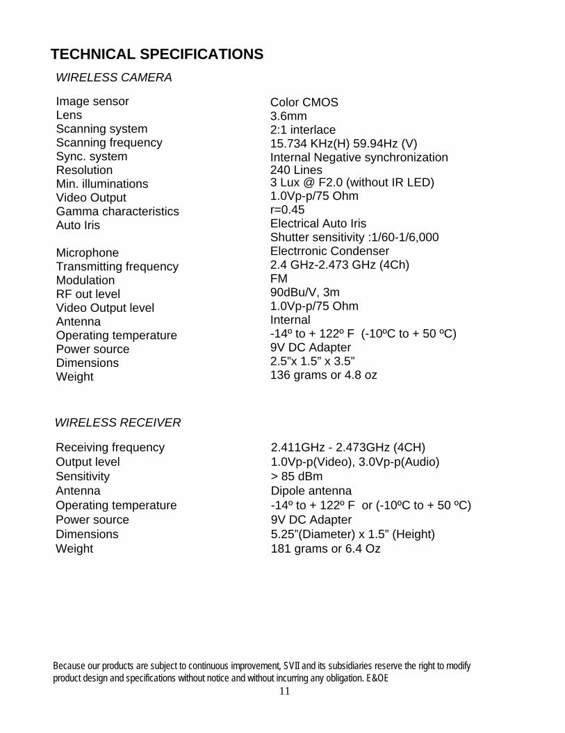
TECHNICAL SPECIFICATIONS
Because our products are subject to continuous improvement, SVII and its subsidiaries reserve the right to modifyproduct design and specifications without notice and without incurring any obligation. E&OE
11
WIRELESS CAMERA
WIRELESS RECEIVER
Receiving frequencyOutput levelSensitivityAntennaOperating temperaturePower sourceDimensionsWeight
2.411GHz - 2.473GHz (4CH)1.0Vp-p(Video), 3.0Vp-p(Audio)> 85 dBmDipole antenna-14º to + 122º F or (-10ºC to + 50 ºC)9V DC Adapter5.25”(Diameter) x 1.5” (Height)181 grams or 6.4 Oz
Image sensorLens Scanning systemScanning frequencySync. systemResolutionMin. illuminationsVideo OutputGamma characteristicsAuto Iris
MicrophoneTransmitting frequencyModulationRF out levelVideo Output levelAntennaOperating temperaturePower sourceDimensionsWeight
Color CMOS 3.6mm2:1 interlace15.734 KHz(H) 59.94Hz (V)Internal Negative synchronization240 Lines 3 Lux @ F2.0 (without IR LED)1.0Vp-p/75 Ohmr=0.45Electrical Auto IrisShutter sensitivity :1/60-1/6,000Electrronic Condenser2.4 GHz-2.473 GHz (4Ch)FM90dBu/V, 3m1.0Vp-p/75 OhmInternal-14º to + 122º F (-10ºC to + 50 ºC)9V DC Adapter2.5”x 1.5” x 3.5”136 grams or 4.8 oz
CARE AND MAINTENANCE:Please follow these instructions to ensure proper care and maintenance of this system
Keep your monitor and camera dry. If it gets wet, wipe it dry immediately.
Use and store your unit in normal temperature environment. Extreme temperatures can shorten the life of the electronic devices.
Handle the monitor carefully. Dropping it can causeserious damage to the unit.
Occasionally clean the unit with a damp cloth to keepit looking new. Do not use harsh chemicals, cleaning solvents or strong detergents to clean the unit.
Keep the unit away from excessive dirt and dust. It can cause premature wear of parts.
12

It’s all on the web
w w w . l o r e x c c t v . c o m
Product Information
User Manuals
Quick Start Guides
Specification Sheets
Software Upgrades
Firmware Upgrades
V I S I T
Strategic Vista International Inc.
www.lorexcctv.com