23(5$7,1* ,16758&7,216 )25 73( 6(5,(6 (/(&75,& 72548 ... · 6&23( +L )RUFH 73( VHULHV HOHFWULF...
12
OPERATING INSTRUCTIONS FOR TPE SERIES ELECTRIC TORQUE PUMPS (DIGITAL GAUGE) TDS:- 1429 Prepared by:- Malcolm Macfie Approved by:- D Brookes Date: 26/11/18 REV NO:- 01 02 ECO:- 4481 5349 Page 1 of 12 1. SCOPE Hi-Force TPE series electric driven pumps are designed to operate high pressure hydraulic double acting torque wrenches with an operating pressure of 700Bar (10 000 psi). These instructions cover the following models: TPE15D - 110 volt supply 50 Hz TPE16D - 120 volt supply 60 Hz TPE25D - 230 volt supply 50 Hz TPE26D - 230 volt supply 60 Hz TPE45D - 400 volt supply 50 Hz TPE46D - 480 volt supply 60 Hz Refer to name plate on the pump for identification. 2. SAFETY READ ALL OF THIS MANUAL BEFORE OPERATING THE PUMP FAILURE TO OBSERVE THE FOLLOWING WARNINGS COULD RESULT IN SERIOUS BODILY INJURY ● Ensure that all equipment connected to the pump is in good condition and is all rated for 700 bar operating pressure. ● Always stand the pump on a stable level surface during operation. ● Never invert the pump or lay it on its side either in use, transport or in storage. ● Inspect hoses regularly for damage and wear. Do not use hoses that are frayed, kinked, abraded or leaking. ● Never move the pump or torque wrench by pulling the hoses. ● Do not work with hoses sharply bent or kinked. ● Do not handle hoses that are pressurised. Oil escaping under pressure can penetrate the skin causing serious injury. DANGER: If oil is injected under the skin see a doctor immediately. ● Never pressurise uncoupled hose couplers. ● Always use eye, ear and hand protective equipment when using this pump and associated equipment. ● Disconnect the pump from the power source when carrying out maintenance or adjustments (except pressure relief valve adjustments). 3. SPECIFICATIONS The pump is a three speed pump with the following pressure and flow ranges Pressure range (bar) Flow on 50 Hz supply (l/min) Flow on 60 Hz supply (l/min) 0-65 6.5 7.8 65-325 1.5 1.8 325-700 0.75 0.9 Weight 36 kg (including oil) Useable oil capacity 7 litres Max sound pressure level 88 dB(A) Maximum oil temperature 80 º C
Transcript of 23(5$7,1* ,16758&7,216 )25 73( 6(5,(6 (/(&75,& 72548 ... · 6&23( +L )RUFH 73( VHULHV HOHFWULF...

OPERATING INSTRUCTIONS FOR TPE SERIES ELECTRIC TORQUE PUMPS (DIGITAL GAUGE)
TDS:-
1429
Prepared by:- Malcolm Macfie Approved by:- D Brookes Date: 26/11/18 REV NO:- 01 02
ECO:- 4481 5349
Page 1 of 12
1. SCOPE Hi-Force TPE series electric driven pumps are designed to operate high pressure hydraulic double acting torque wrenches with an operating pressure of 700Bar (10 000 psi). These instructions cover the following models: TPE15D - 110 volt supply 50 Hz TPE16D - 120 volt supply 60 Hz TPE25D - 230 volt supply 50 Hz TPE26D - 230 volt supply 60 Hz TPE45D - 400 volt supply 50 Hz TPE46D - 480 volt supply 60 Hz
Refer to name plate on the pump for identification. 2. SAFETY
READ ALL OF THIS MANUAL BEFORE OPERATING THE PUMP
FAILURE TO OBSERVE THE FOLLOWING WARNINGS COULD RESULT IN SERIOUS BODILY INJURY
● Ensure that all equipment connected to the pump is in good condition and is all rated for 700 bar operating pressure.
● Always stand the pump on a stable level surface during operation. ● Never invert the pump or lay it on its side either in use, transport or in storage. ● Inspect hoses regularly for damage and wear. Do not use hoses that are frayed, kinked,
abraded or leaking. ● Never move the pump or torque wrench by pulling the hoses. ● Do not work with hoses sharply bent or kinked. ● Do not handle hoses that are pressurised. Oil escaping under pressure can penetrate the
skin causing serious injury. DANGER: If oil is injected under the skin see a doctor immediately.
● Never pressurise uncoupled hose couplers. ● Always use eye, ear and hand protective equipment when using this pump and
associated equipment. ● Disconnect the pump from the power source when carrying out maintenance or
adjustments (except pressure relief valve adjustments). 3. SPECIFICATIONS The pump is a three speed pump with the following pressure and flow ranges
Pressure range (bar) Flow on 50 Hz supply (l/min) Flow on 60 Hz supply (l/min) 0-65 6.5 7.8
65-325 1.5 1.8 325-700 0.75 0.9
Weight 36 kg (including oil)
Useable oil capacity 7 litres Max sound pressure level 88 dB(A) Maximum oil temperature 80 º C

OPERATING INSTRUCTIONS FOR TPE SERIES ELECTRIC TORQUE PUMPS (DIGITAL GAUGE)
TDS:-
1429
Prepared by:- Malcolm Macfie Approved by:- D Brookes Date: 26/11/18 REV NO:- 01 02
ECO:- 4481 5349
Page 2 of 12
4. IDENTIFICATION OF COMPONENTS Refer to diagrams on page 3.
1. Oil reservoir
2. Oil temperature/ level gauge
3. Oil filler/ breather cap
4. Motor
5. Oil pressure gauge
6. Adjustable pressure relief valve with locking wing nut.
7. Tool advance coupler (700Bar maximum)
8. Tool retract coupler (90Bar maximum)
9. Electrical control box
10. Oil cooling heat exchanger
11. Heat exchanger fan.
12. Solenoid valve manual override button
13. Control pendant
14. Advance button
15. Auto cycle button
16. Stop button
17. Additional tool ports fitted with blanking plugs.

OPERATING INSTRUCTIONS FOR TPE SERIES ELECTRIC TORQUE PUMPS (DIGITAL GAUGE)
TDS:-
1429
Prepared by:- Malcolm Macfie Approved by:- D Brookes Date: 26/11/18 REV NO:- 01 02
ECO:- 4481 5349
Page 3 of 12

OPERATING INSTRUCTIONS FOR TPE SERIES ELECTRIC TORQUE PUMPS (DIGITAL GAUGE)
TDS:-
1429
Prepared by:- Malcolm Macfie Approved by:- D Brookes Date: 26/11/18 REV NO:- 01 02
ECO:- 4481 5349
Page 4 of 12
5. PREPARATION OF THE PUMP Immediately after unpacking, examine the pump for signs of transit damage and if found contact the shipping company. Depending on the shipping method used, the pump may or may not be supplied already filled with oil. Check the oil level using the Temperature/level gauge (2). During transit the Oil filler/breather cap (3) will have been replaced with a black transit plug. This plug must be removed and the orange filler breather (packed separately) fitted. If the pump needs filling with oil proceed as below.
5.1. FILLING PUMP WITH OIL Stand the pump on a level surface and fill the tank with Hi-force HFO46 oil via the filler breather cap (3) until the oil level is at, or up to approximately 10mm above the upper marker as shown on the level gauge. The pump is self-priming, so is now ready for use.
5.2. POWER SUPPLY Check that the power supply matches the voltage shown on the motor data plate. N.B. Supply voltages vary from country to country. Hi-Force pumps will operate within normal voltage tolerances, but in extreme cases the motor may overheat. One common cause of failure is the use of long extension cables on the mains supply. The pump should be situated as close as possible to the wall outlet. 6. CONNECTION OF TORQUE WRENCH TO PUMP Connect the torque wrench to the pump using Hi-Force type HTWH hoses. All Hi-Force torque equipment is fitted with flat face quick release couplers. Ensure both halves of the couplers are clean before connecting. To connect, simply push the male and female halves together. To disconnect, turn the knurled collar in the direction of the arrow and then slide the collar back in the direction of the second arrow. Do not attempt to connect or disconnect while under pressure. Connect the female coupler on the red hose to the male advance coupler (7). Connect the male end of the black hose to the female tool retract coupler (8). Connect the other ends of the hoses to the torque wrench. N.B. If using torque wrenches other than Hi-Force or wrenches and hoses that have been modified, check that the wrench is connected correctly so that the male high pressure pump coupler (7) is connected to the advance port on the tool. Failure to do this may result in leakage, tool damage or personal injury. Caution: Refer also to torque wrench operating instructions for detailed information on the correct operation of these tools.

OPERATING INSTRUCTIONS FOR TPE SERIES ELECTRIC TORQUE PUMPS (DIGITAL GAUGE)
TDS:-
1429
Prepared by:- Malcolm Macfie Approved by:- D Brookes Date: 26/11/18 REV NO:- 01 02
ECO:- 4481 5349
Page 5 of 12
7. OPERATION
7.1. PENDANT BUTTON FUNCTIONS The control pendant (13) has three buttons which perform all functions of the torque pump. The advance button (14) is a dual function button. Pressing and releasing the button once will start the pump and set the pump to the torque wrench retract mode. Pressing the button a second time makes the torque wrench advance. The pump will continue in this mode until the button is released. The torque wrench will then automatically retract The Auto Cycle button (15) will switch the pump to auto mode. To prevent accidental operation the button must be pressed for a period of 3 seconds in order to switch to auto cycle mode. The torque wrench will then advance and retract automatically until the auto cycle button is pressed again to put the pump back into manual mode. Note that the tool will retract fully before it stops. Pressing the stop button in auto cycle mode will stop the pump immediately. The stop button (16) stops the pump motor and will not allow the pump to start again until the button is twisted to release it. It does not however remove power completely from the electrical control box.
7.2. USE OF THE DIGITAL GAUGE The digital display includes pressure/torque conversion charts for the range of standard Hi-Force tools and for up to five custom conversion charts which can be set by the end user using just the maximum operating pressure and the maximum torque at maximum pressure.
7.2.1. SYSTEM OPERATION The unit has 3 buttons, referred to as A, B and C as labelled bellow:
7.2.1.1. MAIN SCREEN The default screen displayed at power-up displays the pressure or torque for the selected tool.
- Button A switches the display to Metric mode (Bar/Nm) - Button B enters the configuration menu. For tool selection and review of
pressure/torque conversion charts - Button C switches the display to imperial mode (psi/lb.ft)

OPERATING INSTRUCTIONS FOR TPE SERIES ELECTRIC TORQUE PUMPS (DIGITAL GAUGE)
TDS:-
1429
Prepared by:- Malcolm Macfie Approved by:- D Brookes Date: 26/11/18 REV NO:- 01 02
ECO:- 4481 5349
Page 6 of 12
7.2.1.2. CONFIGURATION MENU There are various configuration options available for configuring the gauge
- Button A scrolls left through the menu - Button B selects the displayed menu option - Button C scrolls right through the menu
7.2.1.3. CHOOSE TOOL MODEL MENU
There are a number of standard tool models pre-programmed into the gauge. This menu allows you to select one of them. If the pressure tool is selected, the gauge displays pressure rather than torque. All of the tools can be switched between metric and imperial mode for the main menu.
- Button A scrolls left through the menu - Button B selects the displayed tool - Button C scrolls right through the menu
7.2.1.4. CONFIGURE CUSTOM TOOL (1-5) MENU
The gauge can store conversion charts for up to 5 custom tools. These tools can be configured in either metric or imperial units. However they are configured, they can be switched between metric and imperial display from the main menu.
- Button A allows you to set the tool conversion factor in Nm at 700 bar - Button B exits this menu - Button C allows you to set the tool conversion factor in lbf.ft at 10,000 psi
7.2.1.5. CONFIGURE CUSTOM TOOL IN Nm
The gauge needs to know how many Nm of torque the tool produces at 700 bar input pressure. - Button A decreases the torque value. You can pres and hold the button to change the
value rapidly - Button B saves the setting and exits the menu - Button C increases the torque value. You can press and hold the button to change
the valve rapidly
7.2.1.6. CONFIGURE CUSTOM TOOL IN lbf.ft The gauge needs to know how many lbf.ft of torque the tool produces at 10,000 psi input pressure.
- Button A decreases the torque value. You can pres and hold the button to change the value rapidly
- Button B saves the setting and exits the menu - Button C increases the torque value. You can press and hold the button to change
the valve rapidly
OPERATING INSTRUCTIONS FOR TPE SERIES ELECTRIC TORQUE PUMPS (DIGITAL GAUGE)
TDS:-
1429
Prepared by:- Malcolm Macfie Approved by:- D Brookes Date: 26/11/18 REV NO:- 01 02
ECO:- 4481 5349
Page 7 of 12
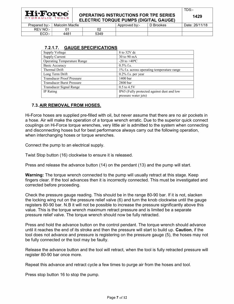
7.2.1.7. GAUGE SPECIFICATIONS
Supply Voltage 8 to 32V dc Supply Current 30 to 90 mA Operating Temperature Range -20 to +40⁰C Basic Accuracy 0.5% f.s. Thermal Drift 1% f.s. across operating temperature range Long Term Drift 0.2% f.s. per year Transducer Proof Pressure 1400 bar Transducer Burst Pressure 2800 bar Transducer Signal Range 0.5 to 4.5V IP Rating IP65 (Fully protected against dust and low
pressure water jets)
7.3. AIR REMOVAL FROM HOSES.
Hi-Force hoses are supplied pre-filled with oil, but never assume that there are no air pockets in a hose. Air will make the operation of a torque wrench erratic. Due to the superior quick connect couplings on Hi-Force torque wrenches, very little air is admitted to the system when connecting and disconnecting hoses but for best performance always carry out the following operation, when interchanging hoses or torque wrenches. Connect the pump to an electrical supply. Twist Stop button (16) clockwise to ensure it is released. Press and release the advance button (14) on the pendant (13) and the pump will start. Warning: The torque wrench connected to the pump will usually retract at this stage. Keep fingers clear. If the tool advances then it is incorrectly connected. This must be investigated and corrected before proceeding. Check the pressure gauge reading. This should be in the range 80-90 bar. If it is not, slacken the locking wing nut on the pressure relief valve (6) and turn the knob clockwise until the gauge registers 80-90 bar. N.B it will not be possible to increase the pressure significantly above this value. This is the torque wrench maximum retract pressure and is limited be a separate pressure relief valve. The torque wrench should now be fully retracted. Press and hold the advance button on the control pendant. The torque wrench should advance until it reaches the end of its stroke and then the pressure will start to build up. Caution, if the tool does not advance and pressure is registering on the pressure gauge (5), the hoses may not be fully connected or the tool may be faulty. Release the advance button and the tool will retract, when the tool is fully retracted pressure will register 80-90 bar once more. Repeat this advance and retract cycle a few times to purge air from the hoses and tool. Press stop button 16 to stop the pump.

OPERATING INSTRUCTIONS FOR TPE SERIES ELECTRIC TORQUE PUMPS (DIGITAL GAUGE)
TDS:-
1429
Prepared by:- Malcolm Macfie Approved by:- D Brookes Date: 26/11/18 REV NO:- 01 02
ECO:- 4481 5349
Page 8 of 12
NB if long hoses are employed (greater than 5 m) then this method will not be totally effective at removing air. Refer to section on pre-filling long hoses.
7.4. SETTING THE TORQUE WRENCH PRESSURE Refer to torque wrench operating instructions, or to conversion charts included in digital gauge, for the pressure setting to achieve the desired torque value. This pressure will vary depending on which torque wrench is being used. Caution: Carry out this pressure adjustment before fitting the wrench onto a bolt or nut. Twist Stop button (16) clockwise to release it. Press and release advance button (14) to start pump. Press and hold the advance button again and allow the torque wrench to fully advance. Keeping the button held down adjust the pressure relief valve (6) by turning the knob clockwise to increase pressure and anticlockwise to reduce pressure. Verify the pressure setting several times by releasing the start/advance button and re-pressing. The pressure setting can be locked at the desired value by tightening the wing nut under the adjusting knob clockwise. Do not use tools for this. To stop the pump, press the red button (16) on the pendant. The pump is now ready for use.
7.5. METHOD OF USE. Refer also to torque wrench operating instructions and bolt torque data. WARNING: It is strongly recommended that operation of the pump and torque wrench is carried out by a single person. This will reduce the possibility of finger trapping accidents due to the wrench being operated while it is still being positioned on the nut or bolt. Where this is not possible due to the relative positions of the pump and the wrench then a clear system of communication needs to be established between users. The pump should be used initially in manual mode until safe reaction points are established, and then it can be switched to auto cycle mode if desired. 8. ADDITIONAL OPERATION HINTS.
8.1. OIL TEMPERATURE CONTROL The pump is fitted with a heat exchanger(10). Oil is circulated through the heat exchanger to restrict temperature rise, while the pump is operating at pressures above 65 bar. A temperature sensor in the oil reservoir switches the cooling fan on when the temperature rises above 45° C to further assist cooling. The fan will switch off as the oil temperature falls back below 40ºC. As a further safeguard, the pump will switch off completely when the temperature rises above 80º C. It will not be possible to re-start it until the temperature falls below 80ºC. Note, that when the pump is stopped, the fan may keep on running until the oil cools to acceptable limits.

OPERATING INSTRUCTIONS FOR TPE SERIES ELECTRIC TORQUE PUMPS (DIGITAL GAUGE)
TDS:-
1429
Prepared by:- Malcolm Macfie Approved by:- D Brookes Date: 26/11/18 REV NO:- 01 02
ECO:- 4481 5349
Page 9 of 12
8.2. AUTO PRESSURE DUMP FEATURE. Always stop the pump by pressing the stop button (16) before connection or disconnection of hoses. Attempting to disconnect hoses while the pump is running is difficult and can cause leakage or injury. As the pump stops, the solenoid valve is operated briefly to release pressure trapped in the system, thereby making disconnection easier. In the event of a power failure, this feature will not function. The manual override button on the top of the valve (12) can be pressed briefly to dump trapped in oil and allow easy hose disconnection.
8.3. CONNECTION OF ADDITIONAL TORQUE WRENCHES The pump has the facility to drive up to 4 torque wrenches simultaneously. These will all operate at the same pressure. This feature can be useful for even tightening of large joints. However it must be borne in mind that multiple torque wrenches will operate more slowly than a single wrench, so it is not necessarily a time saving method. To use this feature, switch off the pump and disconnect from the mains. Remove blanking plugs (17) and fit the desired number of extra pairs of couplers. It is important to fit the male coupler to the top port and the female coupler to the bottom port to ensure correct torque wrench connection. Thread size in the ports is ¼” NPT. Suitable thread sealant or PTFE tampe must be used on the thread. Hi-Force can supply torque coupler sets as follows: TP-CS1 : torque coupler set to convert TPE pump from one outlet to two outlets TP-CS2 : torque coupler set to convert TPE pump from one outlet to three outlets TP-CS3 : torque coupler set to convert TPE pump from one outlet to four outlets 9. MAINTENANCE The oil level in the reservoir should not be allowed to fall below the lower marker on the level indicator (2) during use. (check oil level with torque wrench in advance position.) Keep the reservoir topped up with Hi-Force HFO46 oil. If the oil level does fall below the minimum level then air will be drawn into the pump causing erratic operation and possible damage.
Oil should be replaced after approximately 500 working hours, or more frequently in dusty conditions. To replace the oil, disconnect from electrical supply, remove the filler breather cap (3) and tip used oil out of tank. Dispose of oil in a responsible manner. Refill with Hi-Force HFO46 oil. Regularly inspect the electrical cables for damage. If any damage is evident, these must be replaced by a Hi-Force authorised repair centre or by a competent electrician. Pressure gauge should be calibrated at least every 12 months.

OPERATING INSTRUCTIONS FOR TPE SERIES ELECTRIC TORQUE PUMPS (DIGITAL GAUGE)
TDS:-
1429
Prepared by:- Malcolm Macfie Approved by:- D Brookes Date: 26/11/18 REV NO:- 01 02
ECO:- 4481 5349
Page 10 of 12
10. TROUBLE SHOOTING These pumps should be repaired only by authorised Hi-Force repair centres. The following table gives possible causes and remedies for common problems.
PROBLEM POSSIBLE CAUSE
Tool advances with no pendant buttons pressed.
Tool incorrectly connected. Swap hose connections at tool.
Tool will only reach 80-90 Bar in advance mode, but higher in retract mode.
Tool incorrectly connected. Swap hose connections at tool.
Motor stalls before 700Bar is reached. Low supply voltage. – check voltage.
Motor stops working after prolonged use Oil overheated - allow to cool.
Motor will not start Supply failure – check electrical supply. Electrical control failure - have the electrical system checked by suitably qualified technician.
Pump will not build up or maintain pressure. Leakage from pump or valve components – have the pump inspected by a Hi-Force repair centre
Slow torque wrench operation Leaking seals in torque wrench. Worn piston block elements, leaking relief valve, leaking unloading valve, worn directional valve – have the pump inspected by a Hi-Force repair centre.
11. FILLING OF LONG HOSES BEFORE USE. When long hoses are being used, it is difficult to remove all air in the hose simply by cycling the torque wrench back and forth as described in section 4. A quicker and more effective method is as follows. Connect the female end of one hose to the male coupler on the pump and connect the other end of the same hose to the remaining coupler of the pump. Switch the pump on and allow to run for a few seconds. Switch off and repeat the process with the other hose. After doing this remember to check the oil level in the reservoir.

OPERATING INSTRUCTIONS FOR TPE SERIES ELECTRIC TORQUE PUMPS (DIGITAL GAUGE)
TDS:-
1429
Prepared by:- Malcolm Macfie Approved by:- D Brookes Date: 26/11/18 REV NO:- 01 02
ECO:- 4481 5349
Page 11 of 12
12. PRESSURE CONVERSION CHART
BAR PSI kgf/cm² BAR PSI kgf/cm² 10 145 10.2 360 5221 367.2 20 290 20.4 370 5366 377.4 30 435 30.6 380 5512 387.6 40 580 40.8 390 5657 397.8 50 725 51 400 5802 408 60 870 61.2 410 5947 418.2 70 1015 71.4 420 6092 428.4 80 1160 81.6 430 6237 438.6 90 1305 91.8 440 6382 448.8
100 1450 102 450 6527 459 110 1595 112.2 460 6672 469.2 120 1740 122.4 470 6817 479.4 130 1886 132.6 480 6962 489.6 140 2031 142.8 490 7107 499.8 150 2176 153 500 7252 510 160 2321 163.2 510 7397 520.2 170 2466 173.4 520 7542 530.4 180 2611 183.6 530 7687 540.6 190 2756 193.8 540 7832 550.8 200 2901 204 550 7977 561 210 3046 214.2 560 8122 571.2 220 3191 224.4 570 8267 581.4 230 3336 234.6 580 8412 591.6 240 3481 244.8 590 8557 601.8 250 3626 255 600 8702 612 260 3771 265.2 610 8847 622.2 270 3916 275.4 620 8992 632.4 280 4061 285.6 630 9138 642.6 290 4206 295.8 640 9283 652.8 300 4351 306 650 9428 663 310 4496 316.2 660 9573 673.2 320 4641 326.4 670 9718 683.4 330 4786 336.6 680 9863 693.6 340 4931 346.8 690 10008 703.8 350 5076 357 700 10153 714
OPERATING INSTRUCTIONS FOR TPE SERIES ELECTRIC TORQUE PUMPS (DIGITAL GAUGE)
TDS:-
1429
Prepared by:- Malcolm Macfie Approved by:- D Brookes Date: 26/11/18 REV NO:- 01 02
ECO:- 4481 5349
Page 12 of 12
UK Head Office:
HI-Force Limited Prospect Way, Daventry, Northamptonshire
NN11 8PL United Kingdom
Tel: + 44 1327 301000 Fax: + 44 1327 706555
Email: [email protected]
HI-Force Regional Offices:
Hi-Force Caspian Baku
Azerbaijan Tel: + 994 12 447 4100 Tel: [email protected]
Hi-Force S.r.l. Milan Italy
Tel: + 39 0253 031 088 Email: [email protected]
Hi-Force Hydraulics (Asia) S.B
Selangor Malaysia
Tel: + 603 5525 4203 Email:[email protected]
Hi-Force Nederland By
Numansdorp Netherlands
Tel: + 31 85 902 8111 Email: [email protected]
Hi-Force Hydraulics (Pty) Ltd
Midrand South Africa
Tel: + 27 11 314 0555 Email: [email protected]
Hi-Force Saudi
Dammam Kingdom of Saudi Arabia Tel: + 966 13 802 1338
Email: [email protected]
Hi-Force Hydraulics Abu Dhabi
United Arab Emirates Tel: + 971 2 551 3100
Email: [email protected]
Hi-Force FZCO
Dubai United Arab Emirates Tel: + 971 4 815 0600
Email: [email protected] GLOBAL BRAND. LOCAL SERVICE.
www.hi-force.com