2.3 Gas hydrates - Treccani, il portale del sapere Introduction In general terms, hydrates are...
28
2.3.1 Introduction In general terms, hydrates are compounds which contain water molecules. A very common chemical class of hydrates are hydrated inorganic salts; an example is MgCl 2 6H 2 O, a crystalline form of magnesium chloride. The hydrates described in this chapter represent a different and less well-known family belonging to the clathrate, or inclusion, compounds. These are supramolecular structures in which molecules of one type surround, or cage (the name derives from the Latin clathratus, meaning caged) molecules of another type: the former are described as host molecules and the latter as guest molecules. In the case of natural gas hydrates, the host molecules are water molecules, and the guest molecules are natural gas molecules. This particular situation occurs in the solid phase; the water molecules form a crystalline lattice inside which cavities are generated, which are occupied by the gas molecules. From a macroscopic point of view, the most common form of solid water – ice – can be distinguished from hydrates by their stability even at temperatures significantly above 0°C. The chemical bonds composing the lattice structure formed by the water molecules are of the same type as those determining the structure of different forms of ice: hydrogen bonds. This type of intermolecular bond is characterized by strong directionality, which explains the lower density of ice as compared to liquid water. In the case of hydrates, though, there is a further interaction between the water molecules and the guest molecules, further stabilizing the crystalline phase of the water and raising the melting temperature; as will be seen in more detail below, these are mainly van der Waals bonds, whose energy is capable of overcoming the entropic effect of a highly-ordered structure. The formation of hydrates, unlike ice, depends heavily on pressure; the higher the partial pressure of the gas (in other words the greater the concentration of guest molecules), the higher the hydrate formation temperature. For example, at 0.5 MPa ethane hydrates form at 0.5 o C, whereas at 3.08 MPa they form at 14 o C. 2.3.2 The structure of hydrates The first gas hydrates were discovered by H. Davy in 1811; specifically, Davy noted that pure gaseous chlorine did not solidify at temperatures significantly below 0 o C, whereas in an aqueous solution it was able to induce the water to freeze at temperatures above 0 o C. During the following hundred years, other scientists devoted themselves to the search for molecules able to induce hydrate formation, and simultaneously attempted to estimate the ratio of guest molecules to water molecules; for example, in 1823 M. Faraday proposed the formula Cl 2 10H 2 O, modified to Cl 2 12H 2 O by H.W.B. Roozeboom in 1884. A. De La Rive found sulphur dioxide hydrates in 1829 and proposed the formula SO 2 7H 2 O, corrected to SO 2 11H 2 O by J. Pierre in 1848 and to SO 2 14H 2 O by F. Schoenfeld in 1855. The search for precise stoicheiometric ratios (such as those present in the hydrates of inorganic salts) – the most famous of which is Villard’s rule (1897) postulating a hydration number of 6 – which characterized 19th century research, gradually diminished in the early 20th century, when the absence of a stoicheiometric ratio between the constituents of these substances became clear. At the same time, it was discovered that hydrates did not have an effect on polarized light, unlike the commonest form of ice (hexagonal ice Ih), from which they could thus be easily distinguished. As will be seen below, an important incentive for research on gas hydrates was the discovery in the 85 VOLUME III / NEW DEVELOPMENTS: ENERGY, TRANSPORT, SUSTAINABILITY 2.3 Gas hydrates
Transcript of 2.3 Gas hydrates - Treccani, il portale del sapere Introduction In general terms, hydrates are...

2.3.1 Introduction
In general terms, hydrates are compounds whichcontain water molecules. A very common chemicalclass of hydrates are hydrated inorganic salts; anexample is MgCl2�6H2O, a crystalline form ofmagnesium chloride. The hydrates described in thischapter represent a different and less well-knownfamily belonging to the clathrate, or inclusion,compounds. These are supramolecular structures inwhich molecules of one type surround, or cage (thename derives from the Latin clathratus, meaning caged)molecules of another type: the former are described ashost molecules and the latter as guest molecules. In thecase of natural gas hydrates, the host molecules arewater molecules, and the guest molecules are naturalgas molecules. This particular situation occurs in thesolid phase; the water molecules form a crystallinelattice inside which cavities are generated, which areoccupied by the gas molecules. From a macroscopicpoint of view, the most common form of solid water – ice – can be distinguished from hydrates by theirstability even at temperatures significantly above 0°C.
The chemical bonds composing the latticestructure formed by the water molecules are of thesame type as those determining the structure ofdifferent forms of ice: hydrogen bonds. This type ofintermolecular bond is characterized by strongdirectionality, which explains the lower density of iceas compared to liquid water. In the case of hydrates,though, there is a further interaction between the watermolecules and the guest molecules, further stabilizingthe crystalline phase of the water and raising themelting temperature; as will be seen in more detailbelow, these are mainly van der Waals bonds, whoseenergy is capable of overcoming the entropic effect ofa highly-ordered structure. The formation of hydrates,unlike ice, depends heavily on pressure; the higher the
partial pressure of the gas (in other words the greaterthe concentration of guest molecules), the higher thehydrate formation temperature. For example, at 0.5 MPa ethane hydrates form at 0.5oC, whereas at 3.08 MPa they form at 14oC.
2.3.2 The structure of hydrates
The first gas hydrates were discovered by H. Davy in1811; specifically, Davy noted that pure gaseouschlorine did not solidify at temperatures significantlybelow 0oC, whereas in an aqueous solution it was ableto induce the water to freeze at temperatures above0oC. During the following hundred years, otherscientists devoted themselves to the search formolecules able to induce hydrate formation, andsimultaneously attempted to estimate the ratio of guestmolecules to water molecules; for example, in 1823M. Faraday proposed the formula Cl2�10H2O,modified to Cl2�12H2O by H.W.B. Roozeboom in1884. A. De La Rive found sulphur dioxide hydrates in1829 and proposed the formula SO2�7H2O, correctedto SO2�11H2O by J. Pierre in 1848 and to SO2�14H2Oby F. Schoenfeld in 1855. The search for precisestoicheiometric ratios (such as those present in thehydrates of inorganic salts) – the most famous ofwhich is Villard’s rule (1897) postulating a hydrationnumber of 6 – which characterized 19th centuryresearch, gradually diminished in the early 20thcentury, when the absence of a stoicheiometric ratiobetween the constituents of these substances becameclear. At the same time, it was discovered that hydratesdid not have an effect on polarized light, unlike thecommonest form of ice (hexagonal ice Ih), from whichthey could thus be easily distinguished.
As will be seen below, an important incentive forresearch on gas hydrates was the discovery in the
85VOLUME III / NEW DEVELOPMENTS: ENERGY, TRANSPORT, SUSTAINABILITY
2.3
Gas hydrates

1930s that their formation was capable of blocking thepipeline transportation of natural gas. The search forstructure-properties correlations thus accelerated, andby 1949 an enormous amount of experimental datahad been collected (mainly by D.L. Katz andcolleagues) on the formation conditions for the mainnatural gas hydrates, and M. von Stackelberg proposedthe most important correlation between the size ofguest molecules and the hydration number (Fig. 1). It isinteresting to note that von Stackelberg correctlyobserved both a minimum and maximum limit forhydrate formation. However, Fig. 1 also showsinconsistencies such as the superimposition of the sizeof some ‘formers’ and some ‘non-formers’ derivingfrom a lack of understanding of the crystallinestructure; there are also inaccuracies due to the lack ofexperimental data (such as the classification ofmolecules which do form hydrates as non-formers;examples are oxygen and carbon tetrachloride).
A milestone in the understanding of the propertiesof hydrates was the discovery, a few years later(between 1951 and 1953), by von Stackelberg himselfand W.F.Claussen, L. Pauling, R.E. Marsh andcolleagues, that gas hydrates are clathrate compounds,and the identification of the two main crystallinestructures, named structure I and structure II. Fig. 2shows the unit cells of the two structures, obtained bydirect measurement with X-ray diffraction by G.A.Jeffrey and R.K. McMullan’s research group in the1960s.
86 ENCYCLOPAEDIA OF HYDROCARBONS
HYDROCARBONS FROM NON-CONVENTIONAL AND ALTERNATIVE FOSSIL RESOURCES
Ar
6 H2O
8 H2O
15 H2O
Ne
O2
4
3
5
6
7
8
C6H6
I2CS2
CH2Br2
C2H5I
trans-CH2ClCH2Cl
cis
cis
trans-C3H7Cl
(CCl4)
Kr
Xe
CH4,H2S
CH3Cl, ClO2
CH2Cl2, CHCl3
CH3CHCl2C2H5Cl
C3H8, iso-C4H9C2H5Br
CH3Br, CH3SHBr2
C2H6
CO2
SO2Cl2
PH3
CH3
not h
ydra
te f
orm
ers
hydr
ate
form
ers
no clathratehydrates
no clathratehydrates
max
leng
th o
f th
e m
olec
ule
(Å)
Fig. 1. Von Stackelberg correlation between molecule size and the hydration number (Ripmeester, 2000).
Fig. 2. Crystalline structures of hydrates obtained with X-ray diffraction. A, structure I (McMullan and Jeffrey, 1965); B, structure II (Mak and McMullan, 1965).
A B
Structure IStructure I hydrates are characterized by a cubic
symmetry lattice (space group Pm3m) with the unitcell having sides measuring 1.20 nm. The cavitiesgenerated by the lattice of water molecules are of twotypes: small cavities with a mean radius of 0.395 nmand large cavities with a mean radius of 0.433 nm. Todescribe the structure of the polyhedrons forming thecavities, a nomenclature of XNYM type wasintroduced, where X and Y describe the polygonforming the face and N and M the number of faces.The small cavities are thus described with the symbol512 (twelve pentagonal faces); the large cavities aredescribed with the symbol 51262 (twelve pentagonaland two hexagonal faces). The unit cell consists of 2small cavities and 6 large cavities; a total of 46 watermolecules generates 8 cavities. In the event of totaloccupation, this gives a hydration number of46/8�5.75.
Structure IIStructure II hydrates are characterized by a cubic
symmetry lattice with centred faces (space groupFd3m) with the sides of the unit cell measuring1.70 nm. The cavities generated by the lattice of watermolecules are again of two types: the same type ofsmall cavities (512) with a mean radius equal to orslightly less than 0.391 nm, and large cavities of a newtype (51264, twelve pentagonal and four hexagonalfaces) with a mean radius equal to or greater than0.473 nm. The unit cell is composed of 16 smallcavities and 8 large cavities; a total of 136 watermolecules generate 24 cavities. If all the cavities areoccupied, the hydration number is therefore136/24�5.67.
Hydrates of a single componentIt is interesting to note that the maximum hydration
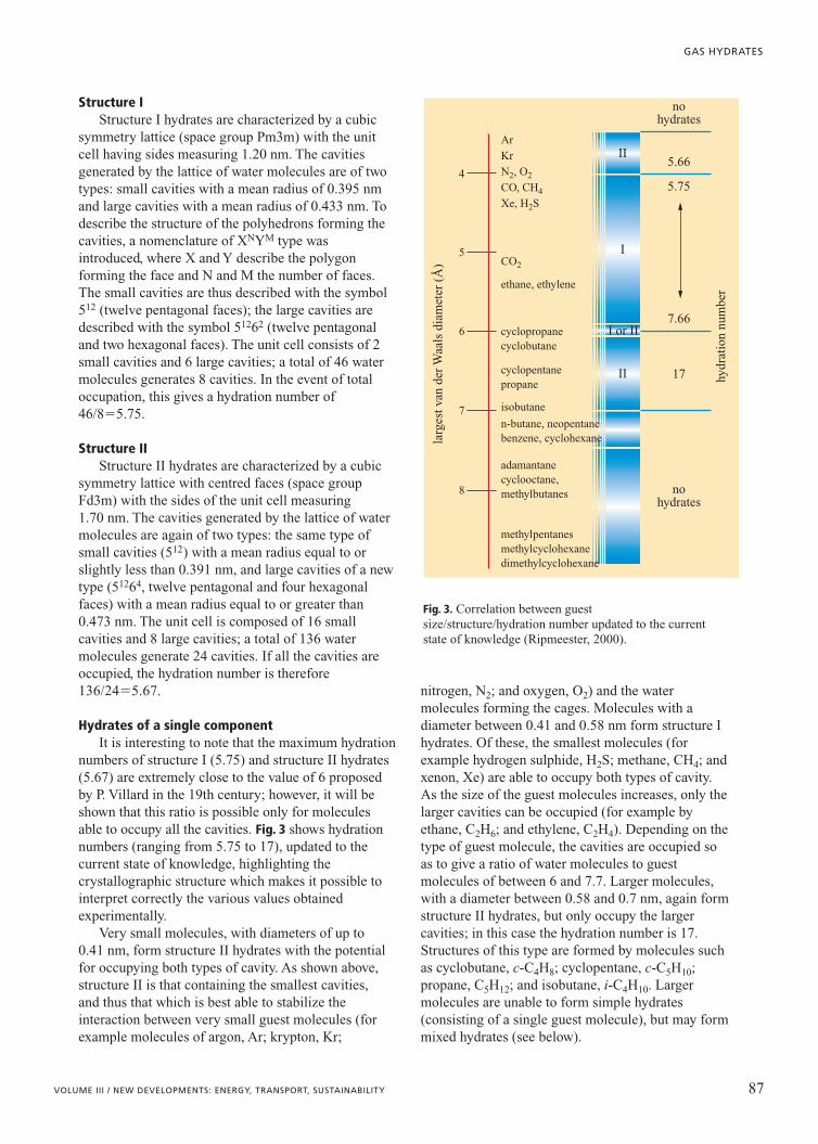
numbers of structure I (5.75) and structure II hydrates(5.67) are extremely close to the value of 6 proposedby P. Villard in the 19th century; however, it will beshown that this ratio is possible only for moleculesable to occupy all the cavities. Fig. 3 shows hydrationnumbers (ranging from 5.75 to 17), updated to thecurrent state of knowledge, highlighting thecrystallographic structure which makes it possible tointerpret correctly the various values obtainedexperimentally.
Very small molecules, with diameters of up to0.41 nm, form structure II hydrates with the potentialfor occupying both types of cavity. As shown above,structure II is that containing the smallest cavities,and thus that which is best able to stabilize theinteraction between very small guest molecules (forexample molecules of argon, Ar; krypton, Kr;
nitrogen, N2; and oxygen, O2) and the watermolecules forming the cages. Molecules with adiameter between 0.41 and 0.58 nm form structure Ihydrates. Of these, the smallest molecules (forexample hydrogen sulphide, H2S; methane, CH4; andxenon, Xe) are able to occupy both types of cavity.As the size of the guest molecules increases, only thelarger cavities can be occupied (for example byethane, C2H6; and ethylene, C2H4). Depending on thetype of guest molecule, the cavities are occupied soas to give a ratio of water molecules to guestmolecules of between 6 and 7.7. Larger molecules,with a diameter between 0.58 and 0.7 nm, again formstructure II hydrates, but only occupy the largercavities; in this case the hydration number is 17.Structures of this type are formed by molecules suchas cyclobutane, c-C4H8; cyclopentane, c-C5H10;propane, C5H12; and isobutane, i-C4H10. Largermolecules are unable to form simple hydrates(consisting of a single guest molecule), but may formmixed hydrates (see below).
87VOLUME III / NEW DEVELOPMENTS: ENERGY, TRANSPORT, SUSTAINABILITY
GAS HYDRATES
4
5
6
7
8
nohydrates
5.66II
II
I
I or II
5.75
7.66
17
nohydrates
larg
est v
an d
er W
aals
dia
met
er (
Å)
Ar
Kr
N2, O2
CO, CH4
Xe, H2S
CO2
ethane, ethylene
cyclopropanecyclobutane
cyclopentanepropane
isobutane
n-butane, neopentanebenzene, cyclohexane
adamantanecyclooctane,methylbutanes
methylpentanes methylcyclohexanedimethylcyclohexane
hydr
atio
n nu
mbe
r
Fig. 3. Correlation between guest size/structure/hydration number updated to the current state of knowledge (Ripmeester, 2000).

The second discovery which revolutionized theworld of hydrates came about in 1959; J.M. van derWaals and J.C. Platteeuw developed a statisticalthermodynamic theory to interpret the properties ofgas hydrates (Waals and Platteeuw, 1959). This isprobably the most important example of the industrialapplication of statistical thermodynamics. Thisdiscipline makes it possible to predict macroscopicthermodynamic properties (such as temperature,pressure, volume, enthalpy, etc) by statisticallyprocessing the microscopic parameters defining thesystem. Specifically, van der Waals and Platteeuwdeveloped a theory (indicated below as VdWP)starting from the ideal solid solution model with thefollowing hypotheses: a) each cavity contains at mostone guest molecule; b) the guest molecules behave likeideal gases; c) quantum mechanical effects are notrequired; d ) the cavities are considered perfectlyspherical and the interactions between guest moleculesand water molecules are described by a sphericallysymmetric potential function; e) there are nointeractions between the guest molecules in thevarious cavities; f ) the effect on stability supplied bythe water molecules is independent of the occupationof the cavities by guest molecules since theircontribution is determined by the energy differentialbetween a completely empty hydrate lattice and an icelattice.
One of the fundamental equations in this theory isthe following:
kT[1] �m �13�
ini ln(1�qi)N
where �m, the difference in free energy between ahypothetical empty hydrate lattice and ice, iscorrelated with the hydration number N and withoccupation of cavities qi . This makes it possible todetermine the composition of the hydrates startingfrom �m and the occupation ratio qi �qj. The modelonly requires the interaction potential between guestmolecules and water molecules, which can be obtainedfrom experimental equilibrium measurements; for thispurpose, the most frequently used potentials are thoseof Lennard-Jones type (with two parameters) andKihara type (with three parameters).
Not only does this theory make it possible topredict the structure of hydrates correctly (I or II,depending on the size of the guest molecules), but alsotheir thermodynamic stability conditions, with errorsof less than 1°C.
Mixed hydratesWhen we have a mixture with more than one
component able to form hydrates, we speak of mixedhydrates. Even if there are several guest molecules, the
VdWP theory is able to interpret the mainthermodynamic properties of hydrates. Specifically,the authors themselves, van der Waals and Platteeuw,have demonstrated and explained the presence of anazeotrope in the propane-hydrogen sulphide system(later the presence of azeotropes was also observed forthe pairs methane-ethylene, methane-ethane,methane-propane and methane-tetrafluoromethane).Azeotropes are often present in liquid-vapourequilibria; these mixtures have the same compositionin both phases. They are therefore difficult mixtures topurify, since distillation techniques cannot be used; inthe transitions between the liquid and vapour phasethere is no change in the concentration of eithercomponent of the mixture. The ability to predict thissituation is therefore important proof of the VdWPtheory’s validity.
In the case of an azeotrope in the solid(hydrate)-vapour equilibrium, the invariability ofcomposition in the two phases is due to the differentpreference of the two compounds for the two types ofcavity. Specifically, for the example H2S-C3H8 shownin Fig. 4, the mixture’s structure II is more stable(hydrates form at lower pressures) than the hydrates ofindividual components, since hydrogen sulphideadapts especially well to the structure’s small cavities,whilst the large propane molecule can only fill thelarger cavities. Later, in 1982, G.D. Holder andD.J. Manganiello showed analytically that azeotropescan only exist for ternary systems (in other words fordouble hydrates, with water as the third component).
Another more recent example of the validity andpower of the VdWP theory concerns the discovery of
88 ENCYCLOPAEDIA OF HYDROCARBONS
HYDROCARBONS FROM NON-CONVENTIONAL AND ALTERNATIVE FOSSIL RESOURCES
pres
sure
(kP
a)
0
150
100
50
hydrogen sulphide (mole fraction)
hydrogen sulphide-propaneazeotrope at 270 K
ice-hydrate
vapour-ice
azeotrope
0.0 0.2 0.4 0.6 0.8 1.0
Fig. 4. Azeotrope for the propane-hydrogen sulphide-water system.

the existence of thermodynamic conditions underwhich the methane-ethane mixture is stable instructure II, although both pure molecules formstructure I hydrates. This hydrate I-hydrate II phasetransition was identified using Raman spectroscopyand nuclear magnetic resonance (Subramanian et al.,2000). Fig. 5 shows the Raman spectra which clearlyindicate the phase transition from structure I tostructure II in the methane concentration interval(mole fraction) between 0.722-0.750.
Raman spectroscopy has shown itself to be anessential tool for studying the properties, boththermodynamic and kinetic, of gas hydrates. This typeof spectroscopy, using laser sources, works withenergy values able to interfere with the vibrations ofthe molecules, situated roughly in the infrared zone ofthe spectrum of electromagnetic waves. Specifically,vibrations are induced which generate variations inpolarizability (unlike more conventional IRspectroscopy techniques which generate variations inthe dipoles). Considering, for example, thesymmetrical stretching vibrations between the C�Hbonds in methane, Fig. 6 shows that these valueschange depending on whether the methane is free ortrapped in hydrate cages. In the latter instance, thisvibration is influenced by the presence of van derWaals interactions between the hydrogen atoms in themethane and the water molecules in the crystallinelattice (the interactions underlying hydrate stability).Studying these vibrations in greater detail, we canobserve that two wavenumbers, and thus two differentfrequencies, are present; each peak represents one ofthe two cavities forming the hydrates. Assuming that
the intensity of the signal is identical for both cavities,analysing the areas beneath the two peaks makes itpossible to determine their occupancy (this is ofparticular importance in kinetic studies where theformation of the two types of cavity may occur atdifferent velocities).
New structuresInclusion compounds formed by associations of
polyhedrons may have a wide range of possible
89VOLUME III / NEW DEVELOPMENTS: ENERGY, TRANSPORT, SUSTAINABILITY
GAS HYDRATES
inte
nsit
y
2,840
xCH4= 0.921
C–H region
xCH4= 0.851
xCH4= 0.750
xCH4= 0.722
xCH4= 0.676
xCH4= 0.628
2,860 2,880
2,887.3C2H6 (II)
2,891.2C2H6 (I) CH4
largeCH4small
2,945.2C2H6 (I)
2,942.3C2H6 (II)
2,900 2,920 2,940 2,960
II
II
II
I
I
I
2,980
Fig. 5. Raman spectraof the C–H region for six differenthydrates of CH4 andC2H6 obtained at 274.2K (Subramanian et al.,2000). The x-axis showsthe wavenumber (equal to the inverse of the wavelength).
inte
nsit
y
2,880 2,890 2,900 2,910 2,920 2,930
C–H region of methane
2,915
2,913.72,903.7
2,904.8
2,917.9
CH4 vapour
pure CH4 hydrate
CH4/THF hydrate CH4largecavity
CH4smallcavity
(structure II)
(structure I)
Fig. 6. Raman spectra of the symmetrical stretching of methane in the vapour phase (2.07 MPa, 298 K), ofmethane in a structure I hydrate (2.97 MPa, 274.2 K) and of methane in the presence of THF in a structure IIhydrate (2.07 MPa, 273.2 K) (Subramanian et al., 2000).

structures; in 1984, Jeffrey proposed seven types.Until 1987, however, no hydrates other than those ofcubic structures I and II had been identified. In thatyear, another structure was discovered, no longer cubicbut hexagonal (like the most common form of ice),and therefore described with the symbol H(Ripmeester et al., 1987).
H hydrates are characterized by a hexagonal lattice(space group P6/mmm), with the unit cell havinga�1.21 nm and c�1.01 nm. The cavities formed areof three types: 512 (also present in structures I and II),51268 (twelve pentagonal and eight hexagonal faces)and 435663 (three square, six pentagonal and threehexagonal faces). The unit cell comprises one cavity oftype 51268, two cavities of type 512 and three cavitiesof type 435663, for a total of 34 water molecules.
For H hydrates to be stable, both the small andlarge cavities must be occupied. The fundamentalcharacteristic distinguishing H hydrates from those oftypes I and II is therefore that H hydrates always occuras mixed hydrates. In other words, they require thepresence of at least two different types of guestmolecules, since the molecules able to stabilize thelarger cavities are unable to enter the smaller cavities.H hydrates are formed by molecules with a van derWaals diameter of between 0.72 and 0.86 nm.Examples of possible molecules are: adamantane,(CH)4(CH2)6; cyclooctane, c-C8H16; methylbutane,CH3�C4H9; and the methylpentanes, CH3�C5H11.The smaller molecules, which allow this structure toexist by occupying the smallest cavities, may be:xenon, Xe; hydrogen sulphide, H2S; methane, CH4;and nitrogen, N2.
The reasons for the interest in H hydrates are notpurely scientific, but are also explained by the fact thatthese structures can form from molecules typicallyfound in oil reservoirs and gas condensate reservoirs.To tackle the hydrates problem (see Section 2.3.3) it istherefore necessary to consider this crystalline phaseas well. Thanks to constant updates in theexperimental data, commercial simulators have begunto supply models for H hydrates as well, excludedfrom van der Waals and Platteeuw’s original theory.
More recently, other structures have beenidentified; in particular, it has been found thatdimethylether molecules form a hydrate with atrigonal structure (indicated by the letter T).The structure belongs to space group P321 and thedimensions of the unit cell are a�3.50 nm andc�1.24 nm. Four types of cavity are formed; startingfrom the smallest these are: 425861 (two square andeight pentagonal faces and one hexagonal face), 51263
(twelve pentagonal and three hexagonal faces), 51262 (twelve pentagonal and two hexagonal faces; thelargest cavity in structure I) and 4151063 (one square,
ten pentagonal and six hexagonal faces) for a total of348 water molecules (Udachin et al., 2001).
To complete the overview of crystalline structures,clearly identified using diffraction techniques (bothneutron and X-ray), it is interesting to note that, atextremely high pressures, methane hydrates undergovarious phase transitions towards new structures, firstof hexagonal type named MH-II (at 1.1 GPa) and then of body-centred orthorhombic type MH-III(between 2 and 10 GPa). These studies (Koh, 2002)are driven by research on the composition of thecosmos; it is thought that hydrates exist on severalplanets, including Mars, Saturn, Uranus and Neptune.
Other molecules in mixed hydratesThe presence of several chemical components in
the gas mixture in contact with water allows for theformation of hydrates not only with differentstructures (like structure H), but also with‘conventional’ structures (cubic structures I and II),containing, however, molecules unable to form simplehydrates. This occurs in the presence of moleculeswhich strongly stabilize the crystalline lattice(sometimes known as ‘help gases’); for example,hydrocarbon molecules with a diameter between 0.70and 0.72 nm (benzene, C6H6; normal butane, n-C4H10;cyclohexane, c-C6H12; and neopentane, (CH3)4C) formII hydrates in the presence of nitrogen or oxygen.
An important molecule unable to form‘conventional’ gas hydrates on its own is hydrogen.Until 2002, no scientist had managed to synthesizepure hydrogen hydrates and it was believed that itssmall size prevented formation; in that year, however,a group of American scientists managed to synthesizemultiple hydrogen hydrates by working at extremelyhigh pressures (220 MPa, 249 K; Mao et al., 2002).Multiple hydrates are systems in which there is amultiple occupation of the cavities of the lattice; this iscommon under extremely high pressures. These typesof hydrates have been studied mainly by Russianresearchers (Dyadin et al., 2002), whose work may beimportant for the understanding of hydrates on otherplanets. A few years earlier, however, a group ofChinese scientists had synthesized ‘conventional’hydrogen hydrates in mixtures with hydrocarbons(Zhang et al., 2000). This type of research thenaccelerated, given the importance of creating safesystems with low energy requirements for the storageof an energy vector which may revolutionizetransportation in the near future, and the fact thathydrates may have suitable properties. The sameChinese researchers, and some Western scientists, latershowed that in the presence of tetrahydrofuran (THF; aliquid completely miscible in water which formshydrates at ambient pressure) the formation pressures
90 ENCYCLOPAEDIA OF HYDROCARBONS
HYDROCARBONS FROM NON-CONVENTIONAL AND ALTERNATIVE FOSSIL RESOURCES

for mixed THF and H2 hydrates may be significantlylower than those required to generate hydrates of purehydrogen (below 10 MPa; Florusse et al., 2004; Zhanget al., 2005).
2.3.3 Hydrates as a problemin the oil industry
In 1934, E.G. Hammerschmidt realized that the plugsobstructing natural gas pipelines in the winter monthsconsisted of hydrates. The conditions which occur innatural gas pipelines, onshore in cold regions andoffshore on the sea floor, fall within the hydrate stabilityzone. As early as the 1940s-50s, the correlations needed
to predict hydrate formation conditions on the basis ofthe density and composition of the gas were developed;this information is necessary to evaluate the severity ofthe problem and possible solutions.
Until very recently (the early 1990s), all strategiesbelonged to the family of ‘thermodynamic’ inhibition;in other words, all the solutions aimed to modify theconditions of the whole transported fluids/pipelinesystem, so that it remained constantly in a state ofthermodynamic instability for hydrates. Today,‘kinetic’ inhibition technologies are also beingdeveloped (see Section 2.3.5). There are four possiblethermodynamic strategies, of which three are actuallyused. Fig. 7 shows the thermodynamic hydrateformation conditions for all possible hydrocarbongases. The curves reported in the figure derive fromthe correlation proposed by Katz and colleagues,based on the relative density g
Cl �C2lnP �C3lng �C4(lnP)2��C5lnPlng �C6(lng)2�C7(lnP)3�
[2] T ���C8(lnP)2 (lng) �C9(lnP)(lng)2� �–1
�C10(lng)3�C11(lnP)4��C12(lnP)3(lng) �C13(lnP)2 (lng)2��C14(lnP)(lng)3�C15(lng)4
where T is the temperature in °F and P is the pressurein psi. Table 1. reports the values of the constants C.
It is important to note that hydrates are stable athigh pressures and low temperatures (top left-handcorner of Fig. 7). To move operating conditionsoutside this area, it is possible to: a) lower the workingpressure of the pipeline; b) raise the workingtemperature of the pipeline; c) move the stability curveby changing the composition of the transported fluidswith the reduction of one or more chemicalcomponents; d ) move the stability curve by changingthe composition of the transported fluids with theaddition of one or more chemical components.
91VOLUME III / NEW DEVELOPMENTS: ENERGY, TRANSPORT, SUSTAINABILITY
GAS HYDRATES
pres
sure
(ps
ia)
50
500
1,000
100
4,000
temperature (°F)30 40
methane
0.6 gasdensity
0.70.80.91.0
50 60 70 80
Fig. 7. Correlation proposed by Katz et al. (1959) between gas density (expressed as the density relative to air) and thermodynamic hydrate formation conditions (hydrates form if the pressure and temperature are above the relevant line).
Table 1. Values of the C constants of the correlation obtained in the temperature range 34-62°F (1.11-16.7°C) andthe pressure range 65-1,500 psi (0.45-10.3 Mpa) (Kobayashi et al., 1992)
C1 C2 C3 C4 C5
2.7707715·10�3 �2.782238·10�3 �5.649288·10�4 �1.298593·10�3 1.407119·10�3
C6 C7 C8 C9 C10
1.785744·10�4 1.130284·10�3 5.9728235·10�4 �2.3279181·10�4 �2.6840785·10�5
C11 C12 C13 C14 C15
4.6610555·10�3 5.5542412·10�4 �1.4727765·10�5 1.3938082·10�5 1.4885010·10�6

For obvious reasons, the only strategy not adoptedis the first (reduction of pressure) since this wouldmean reducing flow rates and therefore the mainparameter determining the economic viability oftransportation. The other strategies, with their possiblevariants, are defined on the basis of the individualproperties of each line. Dehydration (the third strategylisted), when possible, is certainly the cheapest andsafest procedure; all large gas transportation linesapply this process.
DehydrationUnderstanding their chemical structure has made it
possible to solve the operational problem of hydrateformation in natural gas pipelines very effectively.Having determined that hydrates are composed ofwater and the transported gas, it became clear that onesolution was to dehydrate the gas stream (since thecomposition of the gas could not be altered). Theproblem was thus reduced to the determination andattainment of the maximum water vapour content inthe gas stream needed to avoid hydrate formation.Over the years, various technologies have beendeveloped for this purpose, the most important ofwhich are glycol dehydration, the use of molecularsieves and cooling.
Before briefly describing these processes, it isimportant to calculate the maximum waterconcentration which is unable to form hydrates.Despite a commonly held notion, even among thoseworking in the sector, hydrates may form even in theabsence of a liquid aqueous phase. If hydrates didnot form in the absence of liquid water, the dew
point would make it possible to identify themaximum concentration of water which can betransported without the danger of hydrate formation.However, this assumption is not thermodynamicallyvalid, as shown in Fig. 8 (methane-water system at4.8 MPa) which makes it clear that for gas systems(zone at the top indicated by the letter V) withcompositions to the right of the dashed line (lowwater concentrations), as temperature decreases,equilibrium with the hydrate phase (indicated withH-V) is reached without the condensation of liquidwater. On the other hand, for higher waterconcentrations (to the left of the dashed line), thecondensation of liquid water (area indicated byV-Lw) takes place before hydrate formation (in theareas H-Lw and H-V). The commonplace notedabove probably has two origins; the first concernsthe data available in the literature. The correlationsused to determine the maximum water content forgaseous hydrocarbon streams, obtained fromexperiments carried out during the first half of the20th century and which reach temperatures of�50°C (Fig. 9), are well known, but unfortunatelyonly consider dew points. Only a few authors havecorrectly stressed that for the lowest temperaturesthese curves do not represent stable values, sinceunder these conditions there is no gas-liquidequilibrium (dew point), but rather a gas-solid(hydrate) equilibrium. On the other hand, these areparticularly difficult measurements to make andvery few studies have been undertaken; there aretherefore no correlations similar to those for dewpoints. There is only a single algorithm in theliterature (Kobayashi et al., 1992) based on only twosets of measurements. It is true that VdWP theoryalso correctly predicts the existence of a hydrate-vapour equilibrium and a minimum water vapourconcentration for the phase transition to occur.However, these are extrapolations obtained on thebasis of interaction potentials constructed fromexperimental measurements in very differentconcentration intervals (gas/solid/liquid equilibria);the results available from thermodynamic simulatorsmay, therefore, have a very low level of accuracy.
The second origin of the idea that hydrates cannotform without free water is of operational type; hydrateproblems in ‘anhydrous’ gas transportation lines arenot reported in the literature. Since evaluations ofwater content are presumably carried out on the basisof dew points, it would appear that the latter correctlyrepresent the maximum concentration of water whichcan be transported. The rarity of problems during theoperation of these pipelines might be due to reasonswhich are not thermodynamic but kinetic and fluiddynamic. The formation of a solid from a gas phase
92 ENCYCLOPAEDIA OF HYDROCARBONS
HYDROCARBONS FROM NON-CONVENTIONAL AND ALTERNATIVE FOSSIL RESOURCES
tem
pera
ture
concentration
V
V-LW
H-LW
H-I
LW-I
LW
H-V
M-H M-LM
LM-H LM-V
CH4H2O
Fig. 8. Temperature-composition plot for the methane-water system at a pressure of 4.8 MPa (Kobayashi and Katz, 1949). The concentration axis is not linear to facilitate reading.

alone is generally a slow process, and the smallquantities of hydrate which may form under theseconditions can certainly be transported by theturbulent gas flow which occurs in transportation lineswithout obstructing them.
Returning to the problem of dehydrationspecifications, there are various guidelines; forexample, many American states require a maximumhumidity of 7 lb/MMscf (112 ppm), whereas in otherregions a dew point of �10°C is commonly required(a specification which is unclear for the reasons notedabove).
We will now briefly describe the technologies usedto obtain these specifications. The most widely usedprocess is certainly glycol dehydration. In this process,the wet gas is contacted with glycol; beinghygroscopic it reduces the quantity of water vapour inthe gas. Glycols (triethylene glycol, TEG; diethyleneglycol, DEG; and monoethylene glycol, MEG areused), as well as having a strong affinity with water,
present low solubility for hydrocarbon gases and areeasy to regenerate (elimination of water). This is atwo-stage process: in the first stage dehydration occursin an absorber where wet gas and glycol flowcountercurrently at high pressure (4.0-8.5 MPa);subsequently, the glycol is regenerated by heating atlow pressure (this is a water/glycol separation processby fractionated distillation).
Another dehydration method is based on the use ofmolecular sieves. In this case, there is no absorptionprocess, but rather a process of adsorption onto solidsurfaces. This technology is used when very highlevels of dehydration are required (in the order of1 ppm) and, therefore, is often positioned downstreamof glycol dehydration. The process is semi-continuousin that, after a certain time, the adsorption bed throughwhich the wet gas passes is regenerated by heating.Consequently, two beds are often used alternately.
The third industrial process for dehydrating gasstreams is chilling. The water content decreases as thetemperature is lowered. This technology has theadvantage of recovering condensable gases as well asremoving water. The process involves several coolingstages and the addition of glycol, needed to avoidhydrates forming during the process itself.
The addition of antifreezesWhilst dehydration is therefore the major strategy
for gas transportation lines, the same is not true for theproduction lines linking wells on the sea floor or inarctic regions with the initial gas or oil treatmentfacilities on platforms (whether anchored to the seafloor or floating) or onshore, since the presence ofdehydration facilities on each well head iseconomically unjustifiable. In this case, theconventional strategy is the addition of antifreezes (inoffshore locations, flowlines known as umbilicals areused; these transport various types of additives neededto control production, such as inhibitors to preventhydrate formation, corrosion, the formation ofinorganic scales, wax deposits etc.). As with theformation of ice, it is enough to add a sufficientquantity of antifreeze to the mixture to prevent hydrateformation.
Antifreezes consist of molecules which have a highaffinity with liquid water and low affinity with solidwater; the two most commonly used families arealcohols (or glycols) and inorganic salts. Thethermodynamic inhibitors used in the oil industry forproduction operations are methanol and some ethyleneglycols (mono-, di- or triethylene glycol); for drillingactivities, some inorganic salts are used (NaCl, KCl,CaCl2 and HCOOK) which cannot be used duringproduction since they significantly increase corrosionproblems.
93VOLUME III / NEW DEVELOPMENTS: ENERGY, TRANSPORT, SUSTAINABILITY
GAS HYDRATES
0 1 2 3 4
100200
300
150250
50°F
10,000
20,000
1.0
0.9
0.8
0.70.6 0.8
20 25 30 35molecular weight
total solids in brine
hydrateformation line
corr
ecti
on
correction for gas gravity
correction for salinity
gas gravity
40 45 501.0 1.2 1.4 1.6 1.8
0.900.920.940.96
1.000.98
40,000
60,00080,000
6,0008,000
4,000
2,000
100
200
400
600800
1,000
10 40 80 120 160 200 280
2
4
10
20
40
6080
86
temperature (°F)
Dashed lines aremeta-stable equilibrium.
Actual equilibrium is lowerwater content. Angle is a function
of composition
lb o
f w
ater
/106
ft3 o
f w
et g
as (
at 6
0°F
and
14.
7 ps
ia)
14.7
psi
a25
5010
020
030
0
400
500 80
015
0020
00
3000
10,0
005,00
0
Position of this line isa function of gas composition.
H2O
fro
m b
rin
e
H2O
fro
m w
ater
Fig. 9. Water content in hydrocarbon gases which generates condensation as a function of temperature and pressure (Sloan, 2000).

The performance of thermodynamic inhibitors isgenerally expressed in terms of ‘subcooling’, i.e. thedecrease of the hydrate formation temperature atconstant pressure. The first empirical correlation onthe effect of adding alcohols and glycols was proposedby Hammerschmidt (Fig. 10) and is as follows:
KHW[3] DT �11112244
M(100 �W )
where DT is the subcooling in oC, W is theconcentration of inhibitor expressed as the weightpercentage of the aqueous phase, M is the molecularweight of the inhibitor and KH is the Hammerschmidtconstant; originally the value of the constant was 1,297independent of the inhibitor, but it was later observedthat the equation’s accuracy improved if this constantwas varied for inhibitors other than methanol andethanol. This equation, valid for low concentrations ofadditives (30% for methanol and 20% for glycols) waslater joined by other empirical equations (for examplethat of R.B. Nielsen and R.W. Bucklin).
The result of this correlation should obviously beaccompanied by the definition of the thermodynamicformation conditions (to which subcooling is thenapplied); to this end Fig. 7 shows the formationconditions for hydrocarbon hydrates on the basis ofmeasurements carried out in the 1930s and 1940s onnumerous hydrocarbon gases. It should beremembered that petroleum engineers now havevarious other predictive methods at their disposal, bothof correlative type (such as the K factors method,where K is the ratio of molar fractions of the i-th
component in the vapour phase to the hydrate phase,also proposed by Katz and colleagues during the1940s) and of the type exploiting the theory of van derWaals and Platteuw (commercial simulators). With thelatter, for non-inhibited systems which also containnon-hydrocarbon gases such as carbon dioxide andhydrogen sulphide, the maximum error range is about�2°C.
However, today’s flow assurance engineers cannotbase their work exclusively on this type of information(how much additive to add to the aqueous phase toavoid hydrate formation), since other problems linkedto the use of additives are becoming increasinglyimportant (on new LDHI low dosage additives, seeSection 2.3.5). The problems resulting from the use ofthermodynamic inhibitors during offshore productionare linked to the high environmental impact of usingmethanol (due both to its toxicity and its flammability)and the lower value of the oil sold to refineries whenstrongly contaminated with methanol. To give someidea of the economic impact of using methanol duringoffshore production, it should be remembered that thecosts of supplying methanol alone worldwide amountto around 200 million dollars a year; for methanolcontamination above 100 ppm the penalties applied byrefineries treating the oils produced range from 1 to 5dollars a barrel.
Engineers, who need to evaluate and managehydrate problems, cannot therefore base their workexclusively on equations such as that ofHammerschmidt, which do not take account of thedistribution of the inhibitor between the gas and liquid
94 ENCYCLOPAEDIA OF HYDROCARBONS
HYDROCARBONS FROM NON-CONVENTIONAL AND ALTERNATIVE FOSSIL RESOURCES
pres
sure
(M
Pa)
0
4
2
6
8
10
12
14
16
18
20
temperature (°C)
subcooling
methane
methane�5% MeOH
methane�10% MeOH
methane�15% MeOH
methane�20% MeOH
methane�30% MeOH
�50 �40 �30 �20 �10 0 2010
Fig. 10. Methane hydrateformation conditions as the concentration of methanol varies,according to theHammerschmidtmethod.

phases (oil and water). Even commercial simulators donot present high levels of accuracy in this field(prediction of the composition of the various phases),since the data in the literature on phase compositionare still extremely limited (at least in the publicdomain).
As a consequence, oil companies, or thecontractors to which the design of productioninfrastructure is entrusted on their behalf, often useexperimental measurements. The rigs normally used todetermine the equilibrium conditions for hydrates arevery similar to the conventional PVT (Pressure,Volume, Temperature) cells used for thethermodynamic measurement of reservoir fluids.These are thermostated cells (the most frequently usedmethod involves air baths, but temperature controlsystems with liquids can also be used) equipped withwindows, to measure and vary the volume of the fluids(by determining the position of the gas-liquidmeniscus) and agitate the contents (by rocking the cellitself or with agitation systems inside it). In the past,PVT cells were very simple systems, since mercury(insoluble in hydrocarbons and a poor solvent for thehydrocarbons themselves) was used both as adisplacement fluid (to vary the volume) and as anagitation system (by rocking the cell, mercury’s highdensity made it possible to mix even very heavyhydrocarbon systems). Today, for environmentalreasons, PVT cells without mercury are used; these aretherefore more complex appliances which have pistonsinside the chamber and agitation systems. To carry outmeasurements with hydrates, the PVT cells must becooled to the relevant temperature (conventionalhydrocarbon fluids exist at temperatures which arealways above 50°C); in this case it is unnecessary touse cells with windows (for details of procedureswhich do not require a direct view of the inside of thecell, see below) but it is preferable to do so.
Three procedures can be used, depending on thethermodynamic variable which is kept constant:
isochore (constant volume), isobar (constant pressure)and isotherm (constant temperature). However, somefeatures are common to all procedures: an agitationmethod is needed to allow the system to reachequilibrium states (stable or metastable, see below) ina reasonably short time; during the hydrate formationphase a condition of metastability is always present; tobegin the process of nucleation and growth of hydratecrystals a certain amount of activation energy isneeded, which must be supplied in the form ofoverpressure or subcooling. During the hydratedissolution phase, by contrast, if the process issufficiently slow, there is no metastability.
The isochore procedure was historically the first tobe proposed and is still the most widely used. Thisinvolves using a cell with an agitation and/or rockingsystem, with or without the possibility of seeing thecontents of the cell. First the hydrocarbon phase(s) andthe aqueous phase are loaded, the cell is then broughtto a given pressure and a temperature sufficiently highfor the system to remain stable without hydrateformation. The temperature is then gradually lowered;first, a linear decrease in pressure is observed withtemperature (due to the greater thermal dilation of thegas phase in accordance with Gay-Lussac’s law) andthen a significant drop in pressure indicating theformation of hydrate crystals under metastableconditions. At this point the process is reversed and thetemperature raised; the point at which the P(T ) curveduring heating intersects that obtained during coolingis the (stable) hydrate formation point for thatthermodynamic system. Fig. 11 shows an example ofthe application of this procedure to a gas/water system.
In the isobar procedure the volume must be variedso as to maintain constant pressure. In this procedure,too, the thermodynamic variable controlled istemperature; decreasing the temperature causes alinear reduction of the volume (according toGay-Lussac’s law) until a significant decrease involume indicates the formation of hydrate crystals
95VOLUME III / NEW DEVELOPMENTS: ENERGY, TRANSPORT, SUSTAINABILITY
GAS HYDRATES
pres
sure
(ba
r)
40
41
42
43
44
45
46
47
48
temperature (°C)
hydrate formation onsetunder metastable conditions
equilibrium pointfor hydrate formation
2220181614121086420�2
Fig. 11. Isochoredetermination of hydrateformation conditions in a system containing a natural gas withhigh-speed cooling (1°C/h) and slower heating (0.3°C/h) to ensure stable equilibrium states.
under metastable conditions. Once the hydrates haveformed, the temperature is increased to determine thepoint of thermodynamic equilibrium, which is alwaysdetermined during dissolution to eliminatemetastability. As in the isochore procedure, thehydrocarbon/hydrate/water equilibrium point isdetermined by the intersection of the V(T ) curveobtained during heating with that obtained duringcooling.
In the third procedure (isotherm), thedetermination is made by maintaining a constanttemperature and varying the pressure. In this case, too,the equilibrium point is determined during thedissolution of the hydrates from the intersection of theV(P) curve obtained during depressurization with thatobtained during pressurization.
In principle, laboratories can choose any one of thethree procedures. The isotherm procedure has theundoubted advantage of allowing the experimenter todecide at what temperature to determine equilibriumconditions. In the other two procedures, thetemperature sought is the result of experimentation;moreover, in the isochore procedure the experimenterinitially does not know the equilibrium pressure either.However, the isotherm procedure causes the greatestuncertainty in the determination of the equilibriumvalue since this involves finding the intersection oftwo curves, which generally are not straight lines. Inthis case, the support of visual determination(dissolution of the last crystal) is crucial. Since the useof the PVT cell is normally needed to characterizeoils, for which visual evaluation is not used, thisuncertainty means that this methodology is rarelyused.
In the case of the isobar procedure, the fact thatthese tests involve an automatic variation in volume(needed to maintain constant pressure) makes thisprocedure more subject to safety-related risks; since thereaction kinetics may be varied and unpredictable, the pressure gauge may lose control, generatingvariations in pressure which could result in damagedparts (the windows) of the cell rather than causing theintervention of overpressure rupture systems. In theisochore procedure, by contrast, since there are novariations in volume, there are no moving parts insidethe cell (agitation and/or the rocking of the cell itselfare obviously present in all the procedures) and noautomatic control is required. It is thus easy toconclude that, in its simplicity, the isochore procedureallows for the best safety conditions without loss ofaccuracy (its accuracy is best, alongside that of theisobar procedure). These simple considerations explainwhy this type of procedure is the oldest, but remainsthe most widely used in research andchemico-physical analysis laboratories; moreover, the
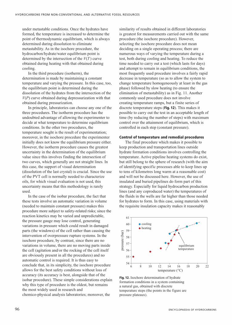
similarity of results obtained in different laboratoriesis greatest for measurements carried out with the sameprocedure (the isochore procedure). However,selecting the isochore procedure does not meandeciding on a single operating process; there arenumerous ways of varying the temperature during atest, both during cooling and heating. To reduce thetime needed to carry out a test (which lasts for days)and attempt to remain in equilibrium conditions, themost frequently used procedure involves a fairly rapiddecrease in temperature (so as to allow the system tochange temperature homogeneously at least in the gasphase) followed by slow heating (to ensure theelimination of metastability) as in Fig. 11. Anothercommonly used procedure does not involve creating temperature ramps, but a finite series ofdiscrete temperature steps (Fig. 12). This makes itpossible to carry out the test in an acceptable length oftime (by reducing the number of steps) with maximumcontrol over the attainment of equilibrium, which iscontrolled in each step (constant pressure).
Control of temperature and remedial proceduresThe final procedure which makes it possible to
keep production and transportation lines outsidehydrate formation conditions involves controlling thetemperature. Active pipeline heating systems do exist,but still belong to the sphere of research (with the aimof identifying specific processes able to keep lines upto tens of kilometres long warm at a reasonable cost)and will not be discussed here. However, the use ofinsulated and buried pipelines do form part of thisstrategy. Especially for liquid hydrocarbon productionlines (and any coproduced water) the temperatures ofthe fluids in the wells are far higher than those neededfor hydrates to form. In this case, using materials withthe requisite insulation capacity makes it reasonably
96 ENCYCLOPAEDIA OF HYDROCARBONS
HYDROCARBONS FROM NON-CONVENTIONAL AND ALTERNATIVE FOSSIL RESOURCES
pres
sure
(ba
r)
54
55
56
57
58
59
60
61
temperature (°C)
equilibriumtemperature
coolingheating
6 8 10 12 14 16 18 20 22
Fig. 12. Isochore determination of hydrate formation conditions in a system containing a natural gas, obtained with discrete temperature steps (the points in the figure are pressure plateaux).

certain that hydrates will not present a problem duringproduction.
Nevertheless, if production is interrupted, after amore or less extended interval (a few hours to severaldays) the temperature of the pipelines falls to criticallevels (especially in deep waters where the seatemperature always falls within the range 3-5oC). Inthis case, the flow assurance engineer must designprocedures to avoid hydrate formation. There arevarious options, and the choice must be made partlyon the basis of other flow assurance problems (mainlylinked to the precipitation of waxes). The mostcommon procedures are: line depressurization, theinjection of methanol, and line displacement with afluid not subject to hydrate formation (gas oil).
This issue is also closely linked to that of‘remedial’ procedures in the event that hydrateformation does occur. Heating, although apparently animmediate way of dissolving hydrate plugs, must beapplied with extreme caution, since the dissolution ofthe hydrates produces an enormous volume of gas (seeSection 2.3.4) able to generate such high pressures asto rupture the pipelines (Fig. 13 A). Such instances arereported in the literature (Sloan, 2000). Hydrate plugsmust therefore only be heated from the sides, anddoing so requires precise knowledge of their positionand the potential for heating in a localized way(extremely difficult for offshore pipelines).
Depressurization also entails significant safetyproblems. In order to dissolve, hydrates need heat (thisis an endothermic process) and duringdepressurization this occurs not in a longitudinaldirection, but radially from the outside towards thecentre (the necessary heat is supplied by theenvironment outside the pipeline). If the overpressureabove the plug is high, it may become detached fromthe pipeline and move like a projectile, rupturingvalves or bends (Fig. 13 B). This type of situation isalso reported in the experience of offshore operations(Sloan, 2000). When dissolving a plug bydepressurization, it is therefore important to workfrom both sides of the plug itself (if it is known thatthere is only one plug) or, in general, to work veryslowly.
To have an effect, the injection of methanol mustbe carried out near the plug; this therefore requires theability to reach the plug with systems such as coiledtubing which, in addition to their high cost, also havesignificant limitations as concerns the maximumdistances reachable (currently 5 km). Dissolution isthen determined by the rate of diffusion of themethanol inside the plug.
Whatever technique is used, remedial operationsfor the presence of hydrate plugs may last weeks. Theeconomic costs (due to delayed production and the
remedial operations) are therefore significant, andjustify the importance attached to hydrate preventiontechnologies, since hydrates often represent the crucialproblem in deciding the type of development for deepoffshore fields.
Gas hydrates and drilling operationsDuring drilling operations in environments
potentially able to form gas hydrates, namely deepwaters and arctic regions (Fig. 14), two types ofproblems may arise: the first are linked to hydrateformation in the event of gas kicks (gas at higherlevels and higher pressures than those of the targetzone); the second are linked to drilling through naturalhydrate deposits present in the subsurface (see Section2.3.4).
During drilling, the accidental formation ofhydrates leads to the muds losing their rheologicalproperties (due both to the formation of further solids– hydrates – and the decrease of the aqueous liquidphase), which may have extremely seriousrepercussions, such as the blockage of the Blow Out
97VOLUME III / NEW DEVELOPMENTS: ENERGY, TRANSPORT, SUSTAINABILITY
GAS HYDRATES
heat addition
pipeline rupture
gashydrate plug
gashydrate plug
where the pipe bends, the hydrate plug canrupture the flowline through projectile impact
if the velocity is high enough, the momentum of the plug can cause pressures
large enough to rupture the flowline
closed valve
Fig. 13. A, rupture of a pipeline due to the heating of a hydrate plug; B, rupture of bends and valves due to the excessive velocity of hydrate plugs (Sloan, 2000).
B
A

Preventer (BOP), the seizure of the drill string or theblockage of the kill line. Fortunately, these types ofincident are described very rarely in the literature.
Problems related to drilling through hydrateformations also seem to be relatively insignificant ifevaluated in terms of the number of references in theliterature in the public domain. A collection of datafrom 2002 (Collett and Dallimore, 2002) suggests thatthe greatest evidence of problems linked to thepresence of hydrates refers to drilling in arctic regions.Specifically, the dissociation of the hydrates oncontact with the drilling mud or casing causes theuncontrolled release of gas (which may causeblow-outs) and the collapse of the casing itself.
The procedures adopted to avoid these situationsmainly involve using precooled drilling muds(between 5 and 20°C) which are made heavier so as tostabilize the hydrates with pressure.
2.3.4 Hydrates as a future energyresource
Considering a methane hydrate with a maximumoccupation of cavities, each unit cell with sides of1.20 nm (volume 1.728 nm3) contains 8 moleculeswhose molecular weight is 16.043 g/mol; it is thuseasy to calculate a methane density of 123 kg/m3.If this density is compared with that of methane understandard conditions (0.1013 MPa and 15°C) of0.68 kg/m3, a 180-fold compression can be calculated.
At low pressures, methane and other gases able to formhydrates are therefore far more compressed within thehydrate structure than in the free gas phase. This factis of scientific importance, since it shows that in thehydrate the water molecules and gas molecules arevery close together (even more so than is usual in thegases themselves), although they are very differentmolecules and have weak bonds such as those of vander Waals. The possible industrial implications areobvious, since hydrates are methane ‘concentrators’.This property has suggested, for example, the use ofhydrates for gas transportation (see Section 2.3.5).
Since hydrate stability conditions (pressure andtemperature) are found in many parts of the Earth, itwas easy to hypothesize that natural deposits of gashydrates might exist in the presence of methanesources. The first announcement of the evidence formethane hydrates being present in natural deposits wasin 1965, when Y. Makogon observed the first hydratesamples in the Siberian permafrost, that part of Russiawhere the superficial layers of the ground arepermanently frozen. Later, in the 1970s, the firstevidence that gas hydrates were also present in themarine sediments of many oceans emerged; asdiscoveries increased, it became clear that thecontinental margins present in the oceans may containenormous quantities of natural gas in the form ofhydrates. A simple thermodynamic analysis, togetherwith data on geothermal gradients, shows that methanehydrates are stable in the permafrost at depths of lessthan 2,000 m, and in the sediments of the ocean floorat depths above about 500 m (Fig. 15).
Natural deposits of gas hydrates are of interest forvarious reasons, since they: a) represent a fossil fuelresource which has not yet been exploited; b) representa carbon reserve to be included in the global carboncycle; c) are a possible cause of instability in subseaslopes; d ) are the natural habitat of communities ofbacteria.
These themes are of importance both for coreresearch in sciences such as geology, geophysics,biology and microbiology, and in the search for energysources for the future of mankind; they are alsoessential to understand the climate variations whichtook place in the past and which may occur again inthe future (a theme directly linked to the emission ofgreenhouse gases into the atmosphere and theresulting rise in the earth’s temperature) or issues to betackled during the production of conventionalhydrocarbons in offshore reservoirs (the mechanicalproperties of the sediments represent a variable ofcrucial importance for the planning of drillingoperations and production facilities).
Finally, it is worth briefly mentioning the latestfascinating scientific discovery: extremophile
98 ENCYCLOPAEDIA OF HYDROCARBONS
HYDROCARBONS FROM NON-CONVENTIONAL AND ALTERNATIVE FOSSIL RESOURCES
120° 80° 40°
140° 100° 60°
continuous permafrostsub-sea permafrost
Fig. 14. Arctic regions where permafrost is present (Collett and Dallimore, 2002).

organisms able to live within hydrate deposits on thesea floor have been found (McDonald and Joye, 1997).
The natural abundance of hydratesAuthoritative sources suggest that the methane
present in hydrates may represent the Earth’s largestsource of carbon (Kvenvolden, 1999). This makes itimportant to understand how much methane is actuallytrapped in the subsurface in the form of hydrates(assuming that in the near future technologies willexist allowing for its economic exploitation).
Most of the methane present in natural hydrates isbelieved to be of biogenic origin (generated bybacteria); this gas derives from the biodegradation of
organic material accumulated on the sea floor.Hydrates of this type, studied by coring, are essentiallypure methane (structure I hydrates). However, thereare also natural hydrates of thermogenic gas,containing significant amounts of ethane and propane(structure II hydrates), generated by the gases presentin conventional reservoirs at greater depths which havethen migrated to the surface.
The seismic surveys showing the presence of aBottom Simulating Reflector (BSR) anomaly, and thedrilling operations carried out in the Nankai trough,during some ODP legs (Ocean Drilling Program, themost important international geological programme)and in other offshore locations (Fig. 16), have
99VOLUME III / NEW DEVELOPMENTS: ENERGY, TRANSPORT, SUSTAINABILITY
GAS HYDRATES
A B
dept
h (m
)
1,600
1,400
1,200
1,000
800
600
400
200
0
temperature (K)
geothermalgradient
in permafrost
geothermalgradient
hydrothermalgradient
depth ofpermafrost
sediment water
methanehydrate
methanehydrate
zoneof gas
hydrate
phaseboundary
phaseboundary
geothermal
gradient
base ofgas hydrate
base ofgas hydrate
watersediment
253 263 273 283 293 3031,600
1,400
1,200
1,000
800
600
400
200
0
temperature (K)253 263 273 283 293 303
Fig. 15. Examples of the depth of thehydrate stability zonein possible reservoirs inthe permafrost (A) and in subseaformations (B),calculated on the basisof pressures and thegeothermal gradientsexpected for the area(Kvenvolden andGrantz, 1990).
Fig. 16. Presence of hydrates in the world: black dots indicate the evidence from BSR; white dots indicate coring.
A B

confirmed that hydrates are extremely widespreadalong the continental margins, where thethermodynamic conditions for hydrate formation (seeFig. 15 again) coexist with bacterial methanegeneration processes. This fact, together with theawareness that, unlike conventional oil and gasdeposits, there is no need for the presence of animpermeable layer above the structure to guarantee theexistence of a hydrate reservoir, since the hydratesthemselves are able to fill the pore spaces of marinesediments completely (so that hydrate accumulationscan exist up to a few metres below the sea floor) would
seem to confirm the presence of gigantic quantities ofhydrates on Earth.
This qualitative estimate has not been confirmedby accurate quantitative evaluations. In fact, an in-depth analysis of the available data shows that, despiteefforts to calculate the natural abundance of hydrates,accurate estimates are scarce (Lerche, 2000). Fewindependent estimates made in the period from 1973to 2003 specify clearly the assumptions used in thecalculations (Milkov, 2004). All these measurements,together with A.V. Milkov’s estimate and anotherestimate published subsequently (Klauda and Sandler,
100 ENCYCLOPAEDIA OF HYDROCARBONS
HYDROCARBONS FROM NON-CONVENTIONAL AND ALTERNATIVE FOSSIL RESOURCES
Table 2. Estimates of the abundance of hydrates in offshore conditions(Lerche, 2000; Milkov, 2004; Klauda and Sandler, 2005)
Source Author Year volume (1015 Nm3)
Lerche
A.A. Trofimuk et al. 1977 15
R.F. Meyer 1981 3.1
V.M. Dobrynin et al. 1981 7,600
K.A. Kvenvolden 1988 20
K.A. Kvenvolden e G.E. Caypool 1988 40
G.T. McDonald 1990 21
G.D. Ginsburg e V.A. Soloviev 1998 1
T.S. Collett 2000 0.3
Milkov
A.A. Trofimuk et al. 1973 3,053
A.A. Trofimuk et al. 1975 1,135
N.V. Cherskiy e V.P. Tsarev 1977 1,573
A.A. Trofimuk et al. 1979 120
R.D. McIver 1981 3.1
K.A. Kvenvolden 1988 20
K.A. Kvenvolden e G.E. Caypool 1988 40
G.J. McDonald 1990 20
V. Gornitz e I. Fung 1994 26.4
L.D.D. Harvey e Z. Huang 1995 45.4
G.D. Ginsburg e V.A. Soloviev 1995 1
W.S. Holbrook et al. 1996 6.8
V.A. Soloviev 2002 0.2
A.V. Milkov et al. 2003 4
A.V. Milkov 2004 2.5
Klauda and Sandler J.B. Klauda e S.I. Sandler 2005 120

2005) are reported in Table 2 and Fig. 17. It should bestressed that these measurements refer to offshoreconditions since, according to all the authors cited,onshore conditions represent a tiny part, less than theerror margin in the estimates under consideration.
Milkov’s analysis proposes a subdivision into threeperiods: from 1970 to the early 1980s, from the secondhalf of the 1980s to the early 1990s and from thesecond half of the 1990s until today. Estimates fromthe first period (almost all made by Soviet researchers)are based on very little seismic data, some hydratesamples and extremely rough calculations (simpleproducts of the estimated areas involved, the depth ofthe deposits, the concentration of the hydrates, etc.).These estimates cover a range of three orders ofmagnitude, although most fall into the upper range ofpredictions (1017-1018 Nm3 of methane).
The estimates of the second period (including themost cited estimate by Kvenvolden, often considered aconsensus value, of 21�1015 Nm3) are based, bycontrast, on the assumption that hydrates are not foundin all or almost all the offshore zones with the rightthermodynamic conditions, but almost exclusivelyalong the continental margins. This hypothesis derivesfrom the first evidence for the presence of hydrates:the first seismic campaigns and the discoveries fromBSR readings generated during seismic surveys in thepresence of hydrates in contact with free gas (seeFig. 16 again). A BSR reading is a reflection of seismicwaves occurring at the interface between the hydratelayer (where the propagation rate of the waves is high)and the underlying layer containing gas (where thepropagation rate is much lower). These BSR readingssimulate the sea floor, hence their name. The fact thatonly the continental margins show the presence of
hydrates (unlike other parts of the deep sea floor) isinterpreted to mean that most of the methane is ofbiological origin.
However, the BSR is only a qualitative indicator ofthe presence of hydrates (above free gas) and does notprovide information on their concentration. Theestimates of this second period are thus characterizedby sweeping assumptions for which real evidence islacking (such as the concentration of the hydrates andthe depth of the mineralized levels containinghydrates); however, since the regions of the earthpotentially involved are small, the estimates aregenerally lower than those of the first period.
The most recent estimates (the third period inMilkov’s classification) are based both on BSR mapsand on the first coring campaigns, mainly carried outduring the ODP legs devoted to hydrate reservoirs.These studies have shown two important properties ofhydrate deposits. The first is that hydrates normally donot reach the sea floor, as was believed in the past (seeFig. 15 again), since both the presence ofsulphate-reducing bacteria able to metabolize methanein the presence of sulphates dissolved in sea water, andthe presence of free water in contact with the sea (andtherefore the need for an equilibrium not only betweenthe methane and the water in the sediments, but withthe sea itself) make this impossible; the depth of themineralized layers is therefore shallower than waspreviously thought.
The second property relates to the actualconcentration of hydrates in the deposits, also revealedto be lower than earlier estimates (saturations in therange of 0.4-2% in volume, compared to the 20% involume previously thought). For both these reasons,the estimates have been further reduced; Milkov giveshis own estimate of 1-5�1015 Nm3, one of the lowestvalues reported in Fig. 17.
It certainly cannot be said that this decrease in theestimates is widely accepted. For example, a recentstudy by Klauda and Sandler (2005) again proposes avery high value, similar to the first estimates carriedout (1.2�1017 Nm3). It is also known that manyhydrate deposits cannot be detected withconventional seismic analyses (the only instance ofBSR found in the absence of free gas relates to theCascadia margin, offshore Oregon). Knownexamples of situations where gas hydrates existwithout the presence of BSR include the Gulf ofMexico. The era of resource evaluation makingexclusive use of global mapping by BSR can thus beconsidered definitively over.
New seismic analyses which are more sensitivethan the conventional techniques used for petroleumexploration are being developed. One such techniqueis based on the use of seismometers placed on the sea
101VOLUME III / NEW DEVELOPMENTS: ENERGY, TRANSPORT, SUSTAINABILITY
GAS HYDRATES
1015
Nm
3
0.1
10
100
1,000
10,000
year1970 1980 1990 2000 2010
1
Fig. 17. Estimates of the abundance of hydrates in the offshore areas of the planet. The diamonds represent the values reported by Lerche (2000), squares the values reported by Milkov (2004) and thetriangle the most recent estimate not included in the two earlier sources (Klauda and Sandler, 2005).

floor (OBS, Ocean Bottom Seismometer), and anotheron the deep towed high frequency array (DTAGS,Deep Towed Acoustic Geophysical System; Fig. 18).The advantages of this system, developed specificallyto analyse the first kilometre of marine sediments inwaters up to 6 km deep, offer the potential for workingat great depths and using a high frequency source.Other techniques may be developed in the future,considering that hydrate deposits are never found morethan a few hundred metres below the sea floor. Assuch, these techniques are completely different fromthe conventional seismic surveys aimed at thediscovery of hydrocarbon reservoirs which may belocated thousands of metres below the sea bed,normally carried out using sensors positioned at thesea surface.
Determining the quantity of hydrates from seismicmeasurements is a complex multi-stage process(Carcione and Tinivella, 2000): first, the velocity fieldmust be constructed by inverting the seismic data, thenthe reference state must be known (this can beobtained from seismic measurements of similarlithologies in the absence of gas, or constructed on thebasis of geological knowledge); this makes it possibleto assume that differences between the two velocityfields (anomalies) are due to the presence of hydrates(higher velocities, positive anomalies) and of free gas(lower velocities, negative anomalies). Until now,studies have remained on the qualitative level, makingit possible to distinguish the gas phase and the positionof the base of the hydrate phase (in other words theBSR); to estimate the quantity of hydrates, a model ofpore cementation is also needed. Sensitivity analysesshow that this is the most important factor governingthe accuracy of estimates.
Finally, it is worth mentioning that the coringscarried out in recent years (for example at HydrateRidge on the Cascadia margin or discoveries near mudvolcanoes) have uncovered peculiar situations,characterized by deposits containing large quantities ofmethane (concentrations of up to 43% in volume)which reach the sea floor. It has been discovered thatsuch conditions may exist in the presence of highseepage of thermogenic methane from underlyinglayers, through channels or faults (these are systemswhich continuously release methane into the sea). Thisevidence does not alter the overall estimates, since forthe time being these are isolated instances which aredifficult to predict. However, since the interest inhydrate deposits has mainly economic motivations,these will almost certainly be the deposits selected forproduction.
It is generally agreed that the first hydrates to beexploited economically will probably be those presentin the permafrost; although their actual abundance isunknown, these volumes are nevertheless severalorders of magnitude smaller than those of offshoredeposits (for this reason, no detailed analysis of theirestimates has been reported).
Major projects to characterize natural depositsA complete list of studies aiming to characterize
the world’s hydrate deposits is almost impossible tocompile, since these activities are not always in thepublic domain. For example, two large Asian countries(India and China) place great expectations on thepotential for exploiting their gas hydrate resources.The Indian government has participated actively in amajor international project to study and produce gashydrates in the Canadian permafrost (Mallik project,
102 ENCYCLOPAEDIA OF HYDROCARBONS
HYDROCARBONS FROM NON-CONVENTIONAL AND ALTERNATIVE FOSSIL RESOURCES
conventional surface-tow (e.g. 2 km streamer, 10-80 Hz)
48 channel arrayhydrophone spacing
nominally 15 m
Helmholtzresonator source(250-1,000 Hz)
diameterof 1st
Fresnel zone:63 m
344 m~45°
~45°
500 m
Fig. 18. Diagram of a DTAGS (Deep Towed AcousticGeophysical System).

see below); through various government bodies, Indiais accumulating theoretical and laboratory knowledgeon possible resources present in the Indian Oceanwithin national projects (the first was started in 1996).The public results are scarce, since India has alreadymade the strategic decision to develop its naturaldeposits commercially, and therefore is extremelycautious in divulging its results to potentialcompetitors (Lai, 2004).
In China, research on natural gas hydrates began inthe late 1980s; in 1990, after the first hydrateformation tests at the Lanzhou centre, somegovernment bodies and universities began to studythem. Research covers almost all relevant sectors(Wang, 2004): core research (thermodynamics andkinetics); natural resources surveys (in the SouthChina Sea, the East China Sea and the permafrost ofthe Qinghai-Tibet plateau); the development ofhydrate-based technologies for the oil industry, forwater treatment, separation processes, the foodindustry, bioengineering and the storage of fuel forwarships.
Certainly, however, the country which is investingmost in hydrates is Japan, which, like India, is poor inconventional hydrocarbon resources. The most studiedsite is the Nankai trough, a geological systemgenerated by the collision of two tectonic plates, thatof the Philippine Sea and that of the Eurasiancontinent (Fig. 19), also studied for its repercussions onearthquakes. In the early 1990s, BSR readings werecarried out in this area, leading to estimates of amethane content of 0.4-4�1012 Nm3. Seismic analyseshave multiplied over the years, both in terms of theareas investigated and the technologies adopted.
Drilling campaigns began in 1999, with the objectiveof beginning commercial production in 2016 (the firstproduction test is scheduled for 2007). Japan’s nationaloil companies JAPEX and JNOC (now JOGMEC)have also contributed significantly to the Mallikproject, in the Mackenzie River delta (Canada).
The first phase of such project was conducted alsoby the Geological Survey of Canada (GSC), leading tothe drilling of a second well in the Mackenzie Riverdelta. The Mallik 2L-38 well was completed in 1998,in the vicinity of the first well L-38, which hadidentified gas hydrates during the drilling phasecarried out in 1972 by the Canadian oil company,Imperial Oil, searching for conventional resources.Numerous chemico-physical analyses have beenundertaken, both inside the formation near the well(through logs), and by collecting 37 m of cores insidethe layer containing hydrates (at a depth of between897 and 1,110 m, whereas the layer of permafrost wasidentified up to a depth of 640 m). These analyses(hitherto the most detailed on natural deposits) haveconfirmed that Mallik probably represents one of thesituations with the highest concentration of hydrates inthe world (saturations of up to 80%). According toestimates, it may contain 2.9-4.1�109 Nm3 of gas.
In 2002, the second phase of the project wascarried out with the collaboration, alongside the initialsponsors, of others from the United States, India andEurope. At a cost of around 17 million dollars, adrilling campaign was undertaken in the same area,with the first natural gas hydrate production test. Threewells were drilled: two observation wells 1,160 m deep(Mallik 3L-38 and 4L-38 wells) each at a distance of42.5 m from the central production well, 1,188 m deep
103VOLUME III / NEW DEVELOPMENTS: ENERGY, TRANSPORT, SUSTAINABILITY
GAS HYDRATES
30° N
35° N
130° E 135° E 140° E
Paci
fic
plat
e
BSR distribution area
Nankai trough
Eurasia plate
Philippine Sea plate
400 km
MITI Nankai trough
Tokyo
Kyoto
North America plate
Fig. 19. Location of the Nankai trough.The geological mapshows both the faultsbetween the plates, and the BSR indicatingthe presence of hydrates (JOGMEC-TRC).

(Mallik 5L-38 well). The two observation wells servedto carry out interwell seismics, in order to identifymodifications taking place in the reservoir around thecentral well during and after production tests. Thesame three wells were also equipped with permanentfibre optic temperature sensors, placed inside thecement isolating the well bore. These systems,developed very recently in the field of conventional oiland gas production, are less accurate than normal welllogs (maximum accuracy �0.3°C), but allow for thecontinuous acquisition of temperature curves. Thesensors were used not only during the drilling andproduction phases in March 2002, but also later, afterthe abandonment of the wells, in October 2002 andSeptember 2003. Of particular interest was the factthat the drilling and well completion operations alteredthe temperature of both the permafrost layer and thehydrate layer. The reestablishment of the initialtemperatures (in equilibrium with the formation) tookas long as 21 months (January 2002-September 2003;Fig. 20). The analysis of the geothermal gradientshowed that the hydrates present in the pores have aminimal effect on the thermal conductivity of the rockwith respect to variations in lithology.
During the two production tests (one by simpledepressurization and the other with the injection of hotwater) a maximum flow rate of 350 Nm3/d wasreached. This is obviously not a flow rate of economicvalue, but the tests did not set themselves thisambitious objective (Moridis et al., 2004).
As far as hydrate deposits on sea floors areconcerned, the most studied formation is the Cascadia
margin Hydrate Ridge offshore Oregon (UnitedStates). This is a tectonically active zone where theoceanic Juan de Fuca plate meets the North Americancontinental plate. This site has been the object of twoODP legs, no. 146 in 1994 and no. 204 in 2002. It ischaracterized by the presence of high concentrationsof hydrates, which reach the surface of the sea floordue to substantial methane flows from the underlyinglayers (gas bubbling has been identified and reportedin the literature). Leg 204 was the greatest effort tocharacterize deposits present on the sea floor (the costof the project was 11 million dollars); it lasted abouttwo months and involved the drilling/coring of ninewells in water between 788 and 1,228 m deep, with wells between 9.5 and 540 m deep. Eight of the nine wells were monitored using Logging WhileDrilling (LWD) technologies (electrical resistivity,nuclear magnetic resonance and density). About3,000 m of cores were recovered from 33 holes, from atotal of 3,675 m of cored sediment, exploiting differentsampling systems developed specifically for hydrates.
Finally, it is worth mentioning three projectsfunded by the United States Department of Energy(US-DOE), which started core research in the period1982-92 (with a budget of 8 million dollars). After theinitial phase of the Mallik project and the first fearsabout possible shortfalls in domestic gas reserves after2020, the topic was taken up again in 2000 with amulti-year project costing several tens of millions ofdollars, aiming to begin the commercial production ofgas from hydrates in 2015. The two most importantprojects involve the characterization and evaluation
104 ENCYCLOPAEDIA OF HYDROCARBONS
HYDROCARBONS FROM NON-CONVENTIONAL AND ALTERNATIVE FOSSIL RESOURCES
0
2008 5/8"
5 1/2"
800
850
900
950
1,000
1,050
1,100
1,150
400
600
800
1,000
temperature (°C)
dT/dz (K/km) GR(API) Sh (m3/m3)
casing
dept
h (m
)
DT
S -
loop
con
f igu
rati
on
0 5 10 15
800 0 0 0.5 1.050 10020 40 60
detail of temperature gradient in zoneof gas hydrate occurrences
base of gas hydrateoccurrences
4 d6 d12 d64 d273 d622 d
Fig. 20. Temperature profile in the Mallik 3L-38 observation well. The detail shows the mean temperature gradients (dT/dz), gamma ray logs (GR), and the saturation in hydrates as a fraction of porosity (Sh) in the hydrate occurrence zone (Hennings et al., 2003).

of hydrate reserves in Alaska (project coordinated by BP) and in the Gulf of Mexico (project coordinated by Chevron, with the collaboration ofConocoPhillips, Total, JOGMEC, Schlumberger andHalliburton). Hitherto, significant results have notbeen made public, although expectations are high. Thethird, smaller, project with the collaboration of theAnadarko oil company and the Maurer engineeringfirm, has already provided some interesting answers.This project, which began in 2003 and ended in 2004,had two aims: to test the potential of a new lowenvironmental impact drilling platform, and to drill thefirst well (Hot Ice 1) specifically searching forhydrates on American territory. The site was thought tocontain gas hydrates, both on the basis of a USGS(United States Geological Survey) geological study,and because a well 8 km away had previouslyindicated the presence of hydrates. Drilling confirmedthe existence of the right thermodynamic conditions(pressure and temperature) for hydrate stability (seeFig. 15 again), and the presence of water and gaswhich, however, was found in the free form and not ashydrates. The reasons for this have not yet beenexplained; in the meantime, this unexpected resultmakes the estimates of hydrates present in naturaldeposits even more uncertain.
Production mechanismsThe knowledge of possible production mechanisms
is still in an initial stage; the largest investments in thissector have hitherto been devoted to an understandingof the properties and quantities of natural sediments,rather than possible production technologies. An initialthermodynamic calculation (Sloan, 1998) shows thatthe energy contained in the methane released from anatural hydrate deposit (combustion energy) is aboutfifteen times greater than that needed to dissolve it(sum of the specific heat required to heat the depositto the melting temperature and the hydrate’s latent heatof melting). Having shown that it isthermodynamically advantageous to recover hydrates(the data mentioned was obtained by assuming anideal yield of 100%), possible production mechanismsmay be as follows:• Depressurizing the reservoir by producing the free
gas present inside. This approach has thesignificant advantage of exploiting many of thetechnologies developed in the conventional oilindustry. However, it can be applied only when thehydrate reservoir is in contact with an areasaturated with free gas; in addition, the stronglyendothermic nature of the process may lead to theformation of ice and/or the cooling of otherportions of the reservoir containing hydrates, witha consequent reduction in dissociation.
• Heating by injecting steam or hot water. In thiscase, a heat source is needed, which mayincrease costs. Possible synergies may derivefrom the in loco presence of hot water, such asassociated water from conventional oilreservoirs.
• Injecting antifreezes, such as methanol or glycols.This method is obviously compromised by the highcosts required for the injection of large volumes ofsolvents, but may be exploited during the wellstart-up phase.
• Injecting carbon dioxide. This is the most recentoption; in this case there are some possiblesynergies which might considerably increase itsappeal. The first reason for its attraction lies in thepotential to dispose of carbon dioxide produced byindustrial processes (CO2 sequestration). Thesecond is that this mechanism, unlike the threeoutlined above, does not damage the naturaldeposits by dissolving the hydrates (with theresulting problems of well stability, subsidence,etc.), but turns the methane hydrates into CO2
hydrates. In this case, knowledge is far lessadvanced, and research will be needed to determinethe exchange mechanism. So far, the few studiespresent in the literature have demonstrated thethermodynamic feasibility of the process, sincecarbon dioxide hydrates are more stable than thoseof methane.
• Conventional mining. This approach is the leastattractive, both economically and in terms of environmental impact. In addition to theenvironmental damage caused by such practices,this process is unlikely to avoid the emission intothe atmosphere of methane (a gas with significantgreenhouse effects, which are about twenty timesthose of carbon dioxide).In evaluating the technologies and processes for
developing these resources, there is increasingconsensus for the concept of gas hydrate petroleumsystems, which considers the production of hydrates aspart of the broader issue of conventional oil and gasproduction, thus exploiting the knowledge alreadygained in the production of hydrocarbons. The use ofnumerical modelling of the behaviour of fluids androcks in the sediments, fundamental for the recoveryof conventional resources (so-called reservoirmodelling), is taking its first steps for gas hydratesystems as well (Sawyer et al., 2000). At the sametime, there is an awareness that the processes neededto produce the methane must be tailored to thedifferent types of deposit (hydrates in zones coveredby permafrost, biogenic hydrates present in thecontinental margins or thermogenic hydrates present inthe deep sea floor).
105VOLUME III / NEW DEVELOPMENTS: ENERGY, TRANSPORT, SUSTAINABILITY
GAS HYDRATES

Sea floor stabilityThe presence of hydrates significantly increases
the stability of the sea floor. In fact, the high resolutionseismic measurements used to characterize hydratedeposits have shown that, for example, resistance toshear stresses increases significantly in sedimentscontaining hydrates as compared to those withouthydrates. On the other hand, the conductive faultspresent in numerous sea floors containing hydrates ofthermogenic origin, where there are large methaneflows, are obvious symptoms of the possible fragilityof these deposits. The destabilization of the hydrates,caused by an increase in sea temperature or a decreasein pressure (resulting from a variation in sea-level)may therefore have devastating effects on the stabilityof the sea floor itself.
Knowledge of this subject, however, is extremelylimited (and it is certainly the least familiar topic),both because it requires an in-depth study of theproperties of the deposits, which has begun onlyrecently, and because very little information has beencollected during the long experience of drillingthrough hydrate deposits in the search for conventionalhydrocarbon resources. As already mentioned, there isno evidence for serious destabilization problems inmarine sediments during drilling in zones with aprobable high incidence of hydrates, such as the Gulfof Mexico. This can easily be explained by the factthat these deposits are very shallow and that they weretherefore crossed rapidly with very wide drill-bits, orthat they were simply avoided (drilling in nearby areaswhere the probability that hydrates were present waslower) since the number of wells in deep water
developments is always very small, and moderntechnologies allow for very large deviations in wellgeometry.
The instruments currently available are unable toidentify the presence of hydrates; the large drillingdiameters necessary over the first few metres make theLWDs developed for measuring formation propertiesduring drilling relatively insensitive (the logs areoptimized for the conventional oil and gas zone, wherethe well diameter is much smaller).
Interestingly, most studies on this theme comefrom research on a gigantic subsea slide (the Storeggalandslide) which occurred about 85,000-90,000 yearsago and involved an estimated area of 30,000 km2
(Fig. 21). A giant gas reservoir was found near the slide(Ormen Lange reservoir offshore Norway); for itsdevelopment, it was necessary to evaluate thepossibility of this event reoccurring and damaging theproduction and transportation facilities.
Some of the conclusions of the recent study carriedout by Sultan et al. (2004) are reported below; thisstudy supplies well-founded reasons for thinking thatthe Storegga slide was caused by hydrates melting.The other theory suggested in the past linked it to agigantic earthquake. Sultan and colleagues remind usthat these issues cannot be tackled using simplemodels based exclusively on energy conservation, bothbecause they are unable to calculate the boundaries ofthe hydrate zone correctly (they always predict thepresence of hydrates up to the sea floor, as in Fig. 15,although it is now known that this is an exception dueto extremely high methane flows), and because they donot provide tools for determining the pressure
106 ENCYCLOPAEDIA OF HYDROCARBONS
HYDROCARBONS FROM NON-CONVENTIONAL AND ALTERNATIVE FOSSIL RESOURCES
OrmenLange
Iceland
Faeroes
Shetland
Storegga slide
Traenadjupet
slide
Fig. 21. Location of the Storegga slideoffshore Norway.

generated by the dissociation of hydrates. It is theoverpressure resulting from the released gas whichleads to a decrease in the mechanical resistance of thesediments and thus the potential for causing slides insubsea slopes. To calculate this overpressure it isnecessary to know the concentration of the hydrates,the solubility of the gas and the compressibility of theporous medium containing the hydrates. By analysingthe variations in the solubility of methane withtemperature and pressure, it is observed that hydratesmay dissociate even within the stability zone(pressure-temperature curve). For this reason, slidesmay occur from below, caused by an increase intemperature or pressure; as seen in Fig. 22 A, the lowconcentration of methane in the first metres does notallow hydrates to form even though the slope underconsideration is within the hydrate stability zone; inFig. 22 B, due to an increase in temperature andpressure, the Top of the Gas Hydrate Stability zone(TGHS) moves downwards, some of the hydratesdecompose generating an overpressure in the poresand weakening the sediments, with the subsidence firstoccurring at the base of the slope; in Fig. 22 C, after theinitial failure, gas exchange with the water columninduces further dissolution of the hydrates, giving riseto a second slide.
2.3.5 Research and developmentactivities in the gas hydratessector
Thermodynamic modellingThe statistical thermodynamic theory of van der
Waals and Platteeuw, and its later modifications byvarious research groups (both academic andindustrial), has provided significant results (seeSection 2.3.2), now available to a full range of usersthanks to commercial thermodynamic simulators.However, these models present two major limitations:the first is the need for experimental measurements todetermine the best host-guest chemical interactionpotential; the second derives from some of the theory’sassumptions, which have been revealed to be highlyapproximate.
Specifically, the hypotheses concerning theabsence of interaction between guest molecules andthe non-influence on the water molecule structureby the presence or otherwise of guest molecules inthe cavities make it impossible to explain thedistortions observed in the crystalline structureswhen the gas mixtures are varied. Empirically, thisdistortion of the lattice should be considered withan appropriate choice of interaction potentials,
which no longer represent the potentials measuredusing pure components but an average of all thepossible mixtures considered. This means thatincreasing the accuracy of predictions for mixedsystems tends to decrease those for pure systems,and that different commercial simulators may givedifferent responses, leading to inconsistencies; inany case, extrapolations to conditions dissimilar tothe calibration pressures, temperatures andcompositions of the interaction potentials may beunreliable. A well-founded theory has in fact beentransformed over time into an empirical fitting toolfor experimental data.
107VOLUME III / NEW DEVELOPMENTS: ENERGY, TRANSPORT, SUSTAINABILITY
GAS HYDRATES
A
B
C
TGHS: Top of Gas Hydrate Stability zone
low concentration of methanewhich prevents hydrate
formation over the first meters
hydrate occurrencezone
seafloor
gas
TGHS (for initial temperature and initial pressure)
TGHS (for final temperature and final pressure)
slopefailure
1 hydrate occurrencezone
hydrate zone
hydrate melting at the topof the gas hydrate zone
gas
TGHS (for initial temperature and initial pressure)
TGHS (for final temperature and final pressure)
retrogressive failuresurfaceCH4 exchange
with seawatercolumn
(liquid phase)
2
3
4
5
6 gas
Fig. 22. Diagram of the generation of the slide surfacecaused by the decomposition of hydrates by dissolution(Sultan et al., 2004).

Whereas for most applications of industrial ortechnological interest this tool is able to satisfy allneeds, this is not the case under frontier conditions,such as drilling or production in deep waters, wherepressures may easily exceed 20 MPa, the limit formost of the measurements carried out.
At the same time, the discovery of systems in whichthe cavities present multiple occupations requiresmodelling tools which exceed the capacities of theVdWP model. Theories have thus been developedwhich expressly take into consideration the distortionsof the lattice (particularly by Holder and colleagues atthe University of Pittsburgh; John and Holder, 1985),and guest-guest interactions (Klauda and Sandler of theUniversity of Delaware; Klauda and Sandler, 2002; andTester and colleagues at the Massachusetts Institute ofTechnology; Anderson et al., 2004). Specifically, theselatest models have introduced the use of ab initiocalculations to determine the interaction potential, nolonger obtained empirically from equilibriummeasurements. This approach may make it possible tolink thermodynamic theories to the dynamic aspects ofhydrate formation; there are thus great expectations ofthis research for the development of quantitative kineticmodels, required in all fields of technologicalinnovation relating to hydrates.
Kinetic modellingIn order for hydrates to form, thermodynamic
hydrate stability conditions are needed. However, thisis not sufficient; the system must be in the rightoperational conditions and there must be an adequatetime for the hydrates to form. The kinetic factor is ofcrucial importance to understand the behaviour ofthese compounds. Despite this, theoretical knowledgein this field is still extremely limited. Thisbackwardness, with respect to the evolution ofthermodynamic models, can be attributed to twofactors. The first, intrinsic to the process itself, is thatthe formation of hydrate crystals is complex (withmany stages and numerous potentially crucial factors)and difficult to analyse experimentally (microscopicphenomena in pressurized systems). The second factoris of operational type; only recently have the kineticeffects of hydrate formation attracted applicationalinterest. In the past, when hydrates only represented aproblem in the transportation of conventionalhydrocarbons, technologies relating to hydrates onlyconcerned the thermodynamic aspect, which thusattracted most research funding. The fundamentalissues relating to formation kinetics are:• How much time is needed for hydrate crystals to
begin to form starting from a given mixture undera given temperature and pressure conditions(induction time).
• What the growth rate of the crystals is.As regards the first issue, the process known as
nucleation must be analysed; in other words, theappearance of aggregates similar to hydrates (nuclei)of sufficiently large size (critical dimension) for thedisordered vibrations of the chemical species not todestroy them, but lead to the formation of crystals.Specifically, we speak of homogeneous nucleation ifthe nuclei consist only of the chemical species whichform hydrates (water and gas), and of heterogeneousnucleation if external factors are involved. Thepresence of reaction sites such as rough surfaces,inorganic deposits, rust etc., encourage heterogeneousnucleation and accelerate the formation of hydrates. Asecond important aspect of nucleation is that it occursat the interface between the gas phase and the liquidphase. This is because the formation of hydratecrystals requires large amounts of water (the molecularwater/gas ratio is about 6 water molecules per gasmolecule, see Section 2.3.2), which significantlyexceeds the saturation of water vapour in the gasphase. Equally, the solubility of hydrocarbons in theaqueous phase is far lower than the concentration ofgas in the hydrate phase. Agitation thus acceleratesformation by generating clean interfaces which arethus available to react. Another typical characteristicof hydrates is the so-called ‘memory effect’; thesuccessive formation of hydrates in the same gas andwater sample occurs with gradually decreasinginduction times. This behaviour appears to show that,even when true nucleation sites are lacking, waterretains a certain structure (water molecules formingpolyhedrons similar to those present in hydrates) ableto help the subsequent formation of hydrates. It hasbeen observed that the memory effect disappears if theaqueous solution is removed from hydrate formationconditions to temperatures above 30-35°C, when themotion induced by temperature is able to destroy thestructure of the water.
As far as the second phase of the formation ofhydrate deposits is concerned, in other words thegrowth of crystals, knowledge is still not at a stageable to develop quantitative predictive models. Whatemerges from the studies conducted is that agitationagain has a significant influence. This case, too, caneasily be explained by remembering that hydrates format the liquid-gas interface, and that they tend to remainthere since their density is intermediate to the othertwo phases (the density of hydrates is similar to that ofice). For growth to occur, the gas must thereforepermeate the hydrate phase and reach the water wherethe growth reaction continues. Agitating the systemfrees the interface of hydrate, increasing the diffusionrate of the gas in the water, which is the factordetermining the overall velocity of the process in one
108 ENCYCLOPAEDIA OF HYDROCARBONS
HYDROCARBONS FROM NON-CONVENTIONAL AND ALTERNATIVE FOSSIL RESOURCES

of the simplest and most commonly used models in theliterature (Skovborg and Rasmussen, 1994).
The experiments described in the literature alsoshow that growth depends on other factors; inparticular, the ability to absorb the high latentheat accompanying the formation of hydrates(DH°�54 kJ/mol for methane) may be the crucialaspect of the entire process in pilot-scale or largerplants. Heating the reaction mixture slows thecrystallization process. In addition, research in thisfield has shown that adding surfactants maysignificantly alter the reaction rate, increasing both thereaction sites and the transportation of reagentsbetween the different phases.
Some research groups have provided models whichinterpolate experiments conducted with laboratoryreactors equipped to measure the temperatures andpressures generated during the process. Hitherto,however, these models are still linked to the originaldata set, and cannot be transferred to different labsystems. It is therefore obvious that there are experimental parameters (differentiating the various experimental set-ups) able to influencekinetics and which have not yet been identified.
Only recently (from the 1990s onwards) havekinetic studies begun using more sophisticatedinstruments. An important improvement, which beganat the Toulouse École Polytechnique (France) andcontinued at the University of Calgary, involvesmeasuring the size of the hydrate particles withsystems based on light scattering. The surface of theparticles, during their growth or dissolution, iscertainly one of the crucial parameters, since it hasbeen observed that diffusion represents a major factor.Various research groups are transferring the potentialof Raman and NMR (Nuclear Magnetic Resonance)spectroscopy techniques from structural to kineticstudies. The interest in hydrates as an energy resourceis also encouraging the use of extremely expensive andspecialized spectroscopic techniques, such as neutrondiffraction or synchrotron light diffraction, in part forkinetic studies; it should be remembered thatcrystallographic structures are measured with X-raydiffraction techniques. The first tests carried out by agroup of researchers from the University of Göttingenshowed that these techniques are more accurate thatconventional techniques using autoclaves, and are ableto identify the presence of reaction intermediates ormetastable phases (Kuhs et al., 2004).
Low dosage inhibitionOne of the industrial sectors in which a greater
understanding of kinetic and superficial effects maylead to substantial modifications of currenttechnologies is the control of hydrate formation in
offshore pipelines. As already mentioned, usingmethanol as a hydrate inhibitor for deep waterreservoirs requires huge volumes of additive; forexample, a small offshore reservoir producing about6 Mm3/d of gas at a pressure of about 30 MPa requiresabout 20 t/d of methanol (Koh, 2002). To overcomethis environmental and safety problem, less toxic lowdosage additives have been developed, which do notrequire special treatments. Using these additives wouldmake it possible to modify the whole hydrate controlstrategy with significant economic effects (resultingboth from the increased value of the oil, notcontaminated with methanol, and the smallerinfrastructure needed).
Over the past 15 years, research and developmenthas been carried out on two families of low dosageinhibitors (LDHI, Low Dosage Hydrate Inhibitors).Neither are able to alter the thermodynamic formationconditions, so they are used under hydrate formationconditions. The first type of additive aims to slow theformation kinetics by acting on the induction time; ifthe residence time of the fluids in the pipelines islower than the induction time, no deposits will form.These are additives of kinetic type (Kinetic Inhibitor,KI). The second type also acts on the kinetics of thehydrates; the nucleation phase is not affected, butrather the subsequent crystal growth phase. The ideathis time is that if the hydrate crystals forming remainsmall and are sufficiently dispersed, no plug will form.These additives, which thus act as dispersants for thehydrate crystals which do form, are known as anti-agglomerants (AA).
However, no additives have hitherto beenidentified, either of kinetic or anti-agglomerant type,able to operate under the conditions typical ofdeepwater (subcooling over 20°C). In this case, too, inorder to create new and more effective additives,efforts are being made to understand their workingmechanism using molecular modelling (Anderson etal., 2005).
Self-preservation and monetization of stranded gasIn the early 1990s, two research groups, one in
Russia (Yakushev and Istimin, 1992) and the other inNorway (Gudmundsson et al., 1994), independentlydiscovered that under certain conditions hydrates arekinetically stable at ambient temperature. These resultswere later verified by other groups of researchers;Fig. 23 reports the half-life times (the time needed fortheir concentration to halve) measured by Stern et al.(2001). It is obvious that there is a temperatureinterval between 242 and 271 K in which the half-lifeis in the order of days whereas, for example, abovezero centigrade the half-life of hydrates is only a fewminutes. This behaviour, known as self-preservation or
109VOLUME III / NEW DEVELOPMENTS: ENERGY, TRANSPORT, SUSTAINABILITY
GAS HYDRATES
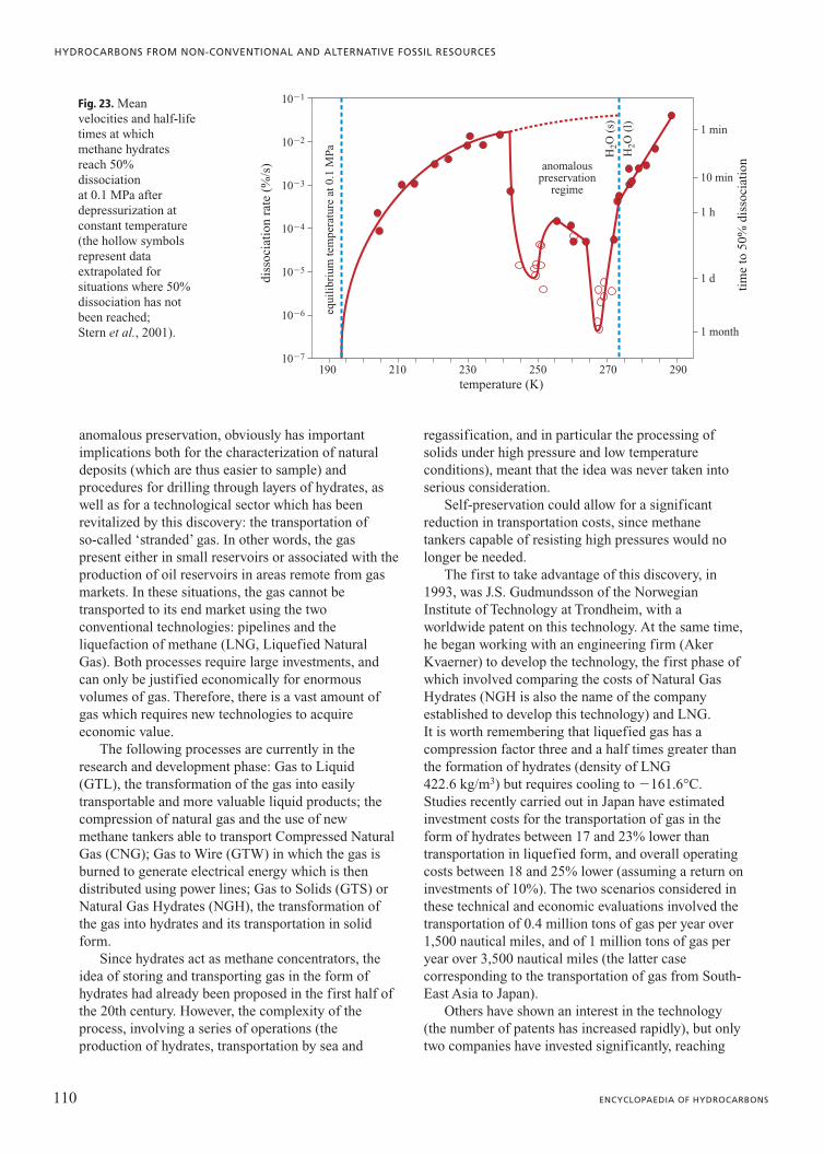
anomalous preservation, obviously has importantimplications both for the characterization of naturaldeposits (which are thus easier to sample) andprocedures for drilling through layers of hydrates, aswell as for a technological sector which has beenrevitalized by this discovery: the transportation ofso-called ‘stranded’ gas. In other words, the gaspresent either in small reservoirs or associated with theproduction of oil reservoirs in areas remote from gasmarkets. In these situations, the gas cannot betransported to its end market using the twoconventional technologies: pipelines and theliquefaction of methane (LNG, Liquefied NaturalGas). Both processes require large investments, andcan only be justified economically for enormousvolumes of gas. Therefore, there is a vast amount ofgas which requires new technologies to acquireeconomic value.
The following processes are currently in theresearch and development phase: Gas to Liquid(GTL), the transformation of the gas into easilytransportable and more valuable liquid products; thecompression of natural gas and the use of newmethane tankers able to transport Compressed NaturalGas (CNG); Gas to Wire (GTW) in which the gas isburned to generate electrical energy which is thendistributed using power lines; Gas to Solids (GTS) orNatural Gas Hydrates (NGH), the transformation ofthe gas into hydrates and its transportation in solidform.
Since hydrates act as methane concentrators, theidea of storing and transporting gas in the form ofhydrates had already been proposed in the first half ofthe 20th century. However, the complexity of theprocess, involving a series of operations (theproduction of hydrates, transportation by sea and
regassification, and in particular the processing ofsolids under high pressure and low temperatureconditions), meant that the idea was never taken intoserious consideration.
Self-preservation could allow for a significantreduction in transportation costs, since methanetankers capable of resisting high pressures would nolonger be needed.
The first to take advantage of this discovery, in1993, was J.S. Gudmundsson of the NorwegianInstitute of Technology at Trondheim, with aworldwide patent on this technology. At the same time,he began working with an engineering firm (AkerKvaerner) to develop the technology, the first phase ofwhich involved comparing the costs of Natural GasHydrates (NGH is also the name of the companyestablished to develop this technology) and LNG.It is worth remembering that liquefied gas has acompression factor three and a half times greater thanthe formation of hydrates (density of LNG422.6 kg/m3) but requires cooling to �161.6°C.Studies recently carried out in Japan have estimatedinvestment costs for the transportation of gas in theform of hydrates between 17 and 23% lower thantransportation in liquefied form, and overall operatingcosts between 18 and 25% lower (assuming a return oninvestments of 10%). The two scenarios considered inthese technical and economic evaluations involved thetransportation of 0.4 million tons of gas per year over1,500 nautical miles, and of 1 million tons of gas peryear over 3,500 nautical miles (the latter casecorresponding to the transportation of gas from South-East Asia to Japan).
Others have shown an interest in the technology(the number of patents has increased rapidly), but onlytwo companies have invested significantly, reaching
110 ENCYCLOPAEDIA OF HYDROCARBONS
HYDROCARBONS FROM NON-CONVENTIONAL AND ALTERNATIVE FOSSIL RESOURCES
diss
ocia
tion
rat
e (%
/s)
equi
libr
ium
tem
pera
ture
at 0
.1 M
Pa
anomalouspreservation
regime
H2O
(s)
H2O
(l)
tim
e to
50%
dis
soci
atio
n
10�1
10�2
10�3
10�4
10�5
10�6
10�7
1 month
1 d
1 h
10 min
1 min
temperature (K)190 210 230 250 270 290
Fig. 23. Meanvelocities and half-lifetimes at whichmethane hydratesreach 50%dissociation at 0.1 MPa afterdepressurization atconstant temperature(the hollow symbolsrepresent dataextrapolated forsituations where 50%dissociation has notbeen reached; Stern et al., 2001).

the stage of building pilot plants for the generation ofhydrates: the British BG and the Japanese MitsuiEngineering and Shipbuilding. However, there are asyet no examples of tests along the wholetransportation chain.
Climate changeAbout 55 million years ago, there was a significant
increase of about 4-8°C in the Earth’s temperature,described as the Late Palaeocene Thermal Maximum(LPTM), which had an enormous impact on life onEarth; new mammals appeared and many species ofmarine animals became extinct. This extraordinaryevent was accompanied by a significant decrease inthe 12C/13C ratio, which has been explained byscientists working on the evaluation of the carboncycle with a significant increase of isotopically lightcarbon dioxide in the seas. Recently, the hypothesishas been advanced that this should be attributed to therelease of methane by unstable hydrate deposits (seeSection 2.3.4); specifically, it has been calculated that1-2�1015 kg of methane would have been needed (Katzet al., 2002). Large amounts of methane enriched in12C, present on the sea floors in the form of hydratesin the first few hundred metres (this is also the currentsituation), began to be released into the sea due to thesea floor instability caused by the temperature increasewhich began in the Late Palaeocene. The gaseousmethane expelled from the sediments then reactedwith the oxygen dissolved in the seawater, producingnew carbon dioxide which thus entered the overallcarbon cycle. Higher temperatures and less oxygendissolved in far more acidic waters killed many of thespecies living in the deep oceans. On land, higherconcentrations of CO2, and therefore increasingtemperatures, led to large migrations of mammals.Over the next 140,000 years the carbon and oxygencycles returned to their original conditions, whilst thealterations in the ecosystem persisted.
Another study has suggested the same process ofrelease of large quantities of hydrates in relation to afar more recent period, the Late Quaternary (Kennet etal., 2003). In this case, the authors do not present suchstrong proof as for the LPTM but, considering theimpact that this scenario would have on climateresearch, this study should help stimulate further morein-depth work on a theory provocatively named the‘clathrate gun hypothesis’. It is clear, in fact, that thepossibility of large quantities of methane beingemitted and accumulated over short periods of time(the last cycle is thought to have occurred about15,000 years ago) would indicate not only that hydratedeposits respond to tiny climate variations, but thatthere is evidence, even in the recent past, of the effectof an increase in greenhouse gases on the climate;
current studies on carbon dioxide emissions caused bythe use of fossil fuels should take this into account.
Studies on the properties of hydrate deposits(stable systems rather than systems under stationaryconditions of continuous release and accumulation)and on their actual size are thus fundamental, not onlyto determine the potential for their exploitation, butalso to improve our knowledge of the climate.
References
Anderson B.J. et al. (2004) Accurate potentials for argon-water and methane-water interactions via ab initio methodsand their application to clathrate hydrates, «Journal ofPhysical Chemistry B», 108, 18705-18715.
Anderson B.J. et al. (2005) Properties of inhibitors of methanehydrate formation via molecular dynamics simulations,«Journal of the American Chemical Society», 127, 17852-17862.
Carcione J.M., Tinivella U. (2000) Bottom simulatingreflectors: seismic velocities and AVO effects, «Geophysics»,65, 54-67.
Collett T.S., Dallimore S.R. (2002) Detailed analysis ofgas hydrate induced drilling and production hazards, in:Proceedings of the 4th International conference on gashydrates, Yokohama, 19-23 May, 47-52.
Dyadin Y.A. et al. (2002) Gas hydrates at high pressure. Stateof the art, in: Proceedings of the 4th International conferenceon gas hydrates, Yokohama, 19-23 May, 590-594.
Florusse L.J. et al. (2004) Stable low-pressure hydrogenclusters stored in a binary clathrate hydrate, «Science»,306, 469-471.
Gudmundsson J. et al. (1994) Storing natural gas as frozenhydrate, «SPE Production and Facilites», February, 69-73.
Henninges J. et al. (2003) Fibre-optic temperaturemeasurements in boreholes, in: Bohrlochgeophysik undGesteinsphysik. Proceedings of the 7th FKPE-Workshop,Hannover, 23-24 October.
John V.T., Holder G.H. (1985) Langmuir constants forspherical and linear molecules in clathrate hydrates. Validityof the cell theory, «Journal of Physical Chemistry», 89,3279-3285.
Katz D.L. et al. (1959) Handbook of natural gas engineering,New York, McGraw-Hill.
Katz M.E. et al. (2002) The source and fate of massive carboninput during the latest Paleocene thermal maximum,«Science», 286, 1531-1533.
Kennet J.P. et al. (2003) Methane hydrates in Quaternaryclimate change. The clathrate gun hypothesis, Washington(D.C.), American Geophysical Union.
Klauda J.B., Sandler S.I. (2002) Ab initio intermolecularpotentials for gas hydrates and their prediction, «Journalof Physical Chemistry B», 106, 5722-5732.
Klauda J.B., Sandler S.I. (2005) Global distribution ofmethane hydrate in Ocean sediment, «Energy & Fuels»,19, 459-470.
Kobayashi R., Katz D.L. (1949) Methane hydrate at highpressure, «Journal of Petroleum Technology», 2579, 66-70.
Kobayashi R. et al. (1992) Phase behavior of water/hydrocarbonsystem, in: Bradley H.B. (editor in chief) Petroleumengineering handbook, Richardson (TX), SPE.
111VOLUME III / NEW DEVELOPMENTS: ENERGY, TRANSPORT, SUSTAINABILITY
GAS HYDRATES

Koh C.A. (2002) Towards a fundamental understanding ofnatural gas hydrates, «Chemical Society Review», 31, 157-167.
Kuhs W.F. et al. (2004) Structural information and kineticdata from diffraction experiments on gas hydrates: quality,assessment and cross-checking with other methods, in:Proceedings of the CODATA Workshop GHDTM04 (GasHydrates Data Task Meeting 2004), Potsdam, 5-6 November.
Kvenvolden K.A. (1999) Potential effects of gas hydrates onhuman welfare, in: «Proceedings of the National Academyof Science», 96, 3420-3426.
Kvenvolden K.A., Grantz A. (1990) Gas hydrates of theArctic Ocean Region, in: Grantz A. et al. (edited by) TheArctic Ocean Region, Boulder (CO), Geological Societyof America, 539- 550.
Lai K. (2004) Indian R&D activities on natural gas hydrates,in: Proceedings of the CODATA Workshop GHDTM04(Gas Hydrates Data Task Meeting 2004), Potsdam, 5-6November.
Lerche I. (2000) Estimates of worldwide gas hydrate resources,«Energy Exploration and Exploitation», 18, 329-337.
McDonald I., Joye S. (1997) Lair of the “ice worm”,«Quarterdeck Online», 5, 3.
McMullan R.K., Jeffrey G.A. (1965) Polyhedral clathratehydrates. IX: Structure of ethylene oxide hydrate, «Journalof Chemical Physics», 42, 2725-2732.
Mak T.C.W., McMullan R.K. (1965) Polyhedral clathratehydrates. X: Structure of double hydrate of tetrahydrofuranand hydrogen sulfide, «Journal of Chemical Physics», 42,2732-2740.
Mao W.L. et al. (2002) Hydrogen clusters in clathrate hydrate,«Science», 297, 2247-2249.
Milkov A.V. (2004) Global estimates of hydrate-bound gasin marine sediments: how much is really out there?, «EarthScience Review», 66, 183-197.
Moridis G.J. et al. (2004) Numerical studies of gas productionfrom several CH4 hydrate zones at the Mallik site, MackenzieDelta, Canada, «Journal of Petroleum Science andEngineering», 43, 219-238.
Ripmeester J.A. (2000) Hydrate research. From correlationsto a knowledge-based discipline: the importance of structure,«Annals of the New York Academy of Science», 912,1-16.
Ripmeester J.A. et al. (1987) A new clathrate hydrate structure,«Nature», 325, 135-136.
Sawyer W.K. et al. (2000) Comparative assessment of naturalgas hydrate production models, in: Proceedings of theSociety of Petroleum Engineers/CERI gas technologysymposium, Calgary (Alberta), 3-5 April, SPE 62513.
Skovborg P., Rasmussen P. (1994) A mass transport limitedmodel for the growth of methane and ethane gas hydrates,«Chemical Engineering Science», 49, 1131-1143.
Sloan E.D. Jr. (1998) Clathrate hydrates of natural gases,New York, Marcel Dekker.
Sloan E.D. Jr. (2000) Hydrate engineering, Richardson (TX),SPE.
Stern L.A. et al. (2001) Anomalous preservation of puremethane hydrate at 1 atm, «Journal of Physical ChemistryB», 105, 1756-1762.
Subramanian S. et al. (2000) Evidence of structure II hydrateformation from methane + ethane mixtures, «ChemicalEngineering Science», 55, 1981-1999.
Sultan N. et al. (2004) Effect of gas hydrates melting onseafloor slope instability, «Marine Geology», 213, 379-401.
Udachin K.A. et al. (2001) A dense and efficient clathratehydrate structure with unusual cages, «Angewandte ChemieInternational Edition», 40, 1303-1305.
Waals J.M. van der, Platteeuw J.C. (1959) Clathratesolutions, «Advances in Chemical Physics», 2, 1-57.
Wang J. (2004) Progress of gas hydrate studies in China, in:Proceedings of the CODATA Workshop GHDTM04 (GasHydrates Data Task Meeting 2004), Potsdam, 5-6 November.
Yakushev V., Istimin V. (1992) Gas hydrates self-preservationeffect, in: Physics and chemistry of ice. Proceedings of theInternational symposium, Sapporo, 1-6 September, 136-139.
Zhang Q. et al. (2005) Hydrate formation conditions of ahydrogen + methane gas mixture in tetrahydrofuran + water,«Journal of Chemical Engineering Data», 50, 234-236.
Zhang S.X. et al. (2000) Hydrate formation conditions ofhydrogen + hydrocarbons gas mixture, «Journal of ChemicalEngineering Data», 45, 908-911.
Gian Paolo BorghiEniTecnologie
San Donato Milanese, Milano, Italy
112 ENCYCLOPAEDIA OF HYDROCARBONS
HYDROCARBONS FROM NON-CONVENTIONAL AND ALTERNATIVE FOSSIL RESOURCES


![New Techniques in Corolling Gas Hydrates [Recovered] Techniques in Corolling Gas Hydrates... · New Techniques in Controlling Gas Hydrates ... Ethane Propane ... • When hydrates](https://static.fdocuments.in/doc/165x107/5b865c467f8b9a195a8ca7ef/new-techniques-in-corolling-gas-hydrates-recovered-techniques-in-corolling-gas.jpg)