2276 SOIL REM BRO FOR PDF - GSPgulfsouthpneumatics.com/wp-content/uploads/2015/05/ev.pdf · Shell...
15
1 IFC Blank
Transcript of 2276 SOIL REM BRO FOR PDF - GSPgulfsouthpneumatics.com/wp-content/uploads/2015/05/ev.pdf · Shell...

1
IFCBlank

2
SVE Blowers 2
Sparging Models 5
Accessories/Service Kits 1 0
Technical Information 1 2
Typical soil remediation systems shown here. Oneutilizes a Gast compressor for sparging and theother a soil vapor extraction blower incombination with a liquid separator and filtrationfor extracting contaminants from the soil.
BLOWER
LIQUIDSEPARATOR
COMPRESSOR
SOILSOIL
IN-LINEFILTER
GAUGE
RELIEFVALVE
GAUGE
INLET FILTER
OUT GASVAPOR
TREATMENT
(PRESSURE)GROUNDW ATER
SPARGING
(VACUUM)SOIL V APOREXTRACTION
W ATER TABLE
CONTAMINANTS
W ATER TABLE
CONTAMINANTS
The information presented in this catalog is based on technical data and test results of nominal units. It isbelieved to be accurate and is offered as an aid in the selection of Gast products. It is the user’sresponsibility to determine suitability of the product for his intended use and the user assumes all riskand liability whatsoever in connection therewith.

3
Gast Manufacturing has aworldwide reputation forquality and customersatisfaction. We supply airmoving products that haveset the industry standardfor excellence since 1921. Among these are quiet-operating,maintenance-freeRegenair ® regenerativeblowers for soil vaporextraction in a completerange of sizes from 1⁄ 3 to10 HP.
3
Practical Design Gast Regenair ® regenerative blowers for soil vaporextraction are rugged industrial grade blowers,engineered for continuous long-life operation.Maintenance free, their only contacting moving partsare the shaft seal and motor ball bearings. Sealed airstreams mean air and vapors passing through theblower do not become contaminated.
Rugged Construction Blower impeller, housing and cover are made of castaluminum which is inherently ductile and spark- andcorrosion-resistant. Exterior castings are vacuumimpregnated with a process conforming to Mil Spec.17563B to eliminate porosity. The fluorocarbonblower shaft seal is lubricated with chemicalresistant non-hydrocarbon grease for long life. Therotating mechanism of the blower and motor isdynamically balanced to prevent vibration. EveryGast Regenair ® blower is performance tested as wellas pressurized and leak-tested to less than 5cc/minute.
Dependable Electric Motors UL and CSA approved motors are multi voltage; mostare dual frequency. Conforming to NEMA frame sizes,
Gast motors on these SVE blowers are classified asEXPLOSION PROOF Division 1 and 2, Class 1, for Group hazardous atmospheres. They are rated for continuousduty and carry full rated load at temperatures belowclass B motor insulation limits. Class F motor insulatiois used in motors larger than 1 HP even though theyoperate at temperatures below class B insulation limits.All motors incorporate UL and CSA approved thermalprotection.
Motor ball bearings are double sealed, with a B10 lifeexceeding 20,000 hours of continuous operation at themaximum rated continuous blower load. This extendedbearing life is achieved by designing the blower andmotor so bearings run cool, avoiding problems associatedwith high temperature bearing operation. Shell DoliumR, a long-life grease with a wide operating- temperaturcapacity and superior resistance to both contaminantsand moisture, is the specified lubricant.
Pilot duty thermal overload protection is standard on all 1 HP and larger explosion proof motors. To conform tothe National Electric Code, motor starters suitable forprotecting motors with pilot duty thermal overloadsmust be used on these motors.
Gast Regenair ® SVE Blower Specifications
SOIL VAPOR EXTRACTION PUMPS– REGENERATIVE BLOWERS
R3105N-50
R4-R7 style

4
Product SpecificationsModel Motor Specifications Max Vac Max Pressure Max Flow Net. Wt.Number Phase Hz Voltages HP Full Load Amps "H 2O mbar "H 2O mbar cfm m 3h lbs kg
R3105N-50 Single 50 110/220-240 .33 4.8/2.4-2.2 28 70 31 77 43 73 52 2460 115/208-230 0.5 5.2/2.9-2.6 40 100 43 107 53 90
R4110N-50 Single 50 110/220-240 0.6 9.2/5.2-4.6 35 87 38 95 74 126 60 2860 115/208-230 1.0 11.4/6.2-5.6 48 120 51 127 92 156
R4310P-50 Three 50 220/380 0.6 3.2/1.6 35 87 38 95 74 126 58 2760 208-230/460 1.0 3.4-3.3/1.6 48 120 51 127 92 156
R4P115N-50 Single 50 110/220-240 1.0 15.2/7.6-8 40 100 45 112 112 190 79 3660 115/208-230 1.5 20.3/11.2-10.6 60 149 65 162 133 226
R5125Q-50 Single 60 115/230 2.0 25/12.5 60 149 55 137 160 272 77 35
R5325R-50 Three 50 190-220/380-415 1.5 5.0-4.4/2.5-2.6 47 117 50 125 133 226 75 3460 208-230/460 2.0 6.6-6.1/3.05 60 149 65 162 160 272
R6130Q-50 Single 50 220-240 2.5 14.7-13.5 65 162 75 187 182 309 129 5960 230 3.0 16.3 70 174 60 149 215 365
R6340R-50 Three 50 190-220/380-415 3.0 14.4-13.4/7.2-6.8 65 162 75 187 180 306 112 5160 208-230/460 4.0 13-12/6 80 199 100 249 215 365
R6P155Q-50 Single 50 220-240 4.0 20.8-19.1 65 162 80 199 235 399 243 11060 230 5.5 29.9 85 212 95 237 280 476
R6P355R-50 Three 50 190-220/380-415 4.5 14.9-11/7.45-5.8 65 162 80 199 232 394 233 10560 208-230/460 6.0 20-18/9 85 212 100 249 280 476
R7100R-50 Three 50 190-220/380-415 8.0 23.2-21.0/11.6-10.9 85 212 90 224 350 595 297 13460 208-230/460 10.0 26.5-24/12 110 274 100 249 420 714
NOTICE: Performance specifications subject to change without notice.
VACUUM
PRESSURE
SOIL VAPOR EXTRACTION PUMPS– REGENERATIVE BLOWERS

5
Product Dimensions (mm) (inches)Model A B C D E F G H I J K L M N OR3105N-50 131 35 310 83 80 281 324 49 99 205 206 238 258 - 13
5.17 1.37 12.20 3.25 3.03 11.06 12.75 1.94 3.88 8.06 8.12 9.38 10.15 - .53R4110N-50 157 43 389 95 72 316 313 50 101 225 227 254 293 175 11
6.18 1.68 15.30 3.75 2.85 12.44 12.31 1.98 3.96 8.86 8.93 10.00 11.73 6.88 .44R4310P-50 157 43 356 95 72 316 313 50 101 225 227 254 293 175 11
6.18 1.68 14.03 3.75 2.84 12.44 12.31 1.98 3.96 8.86 8.93 10.00 11.73 6.88 .44R4P115N-50 177 47 442 114 83 354 338 60 121 260 262 298 346 175 15
6.98 1.84 17.41 4.50 3.25 13.93 13.31 2.38 4.75 10.25 10.31 11.75 13.6 6.88 .60R5125Q-50 178 46 445 114 91 361 344 60 121 260 262 298 350 173 15
7.00 1.82 17.50 4.50 3.58 14.22 13.56 2.38 4.75 10.25 10.31 11.75 13.78 6.81 .59R5325R-50 178 46 423 114 91 361 344 60 121 260 262 298 350 183 15
7.00 1.82 16.66 4.50 3.58 14.22 13.56 2.38 4.75 10.25 10.31 11.75 13.78 7.19 .59R6130Q-50 197 49 511 140 98 404 389 62 125 289 290 329 391 217 13
7.75 1.94 20.13 5.50 3.85 15.89 15.30 2.46 4.92 11.38 11.42 12.96 15.38 8.56 .52R6340R-50 197 49 478 140 98 404 385 62 125 289 290 329 390 217 13
7.75 1.94 18.82 5.50 3.85 15.89 15.17 2.46 4.92 11.38 11.42 12.96 15.34 8.56 .52R6P155Q-50 248 80 602 140 137 438 428 64 127 - 290 325 463 257 13
9.77 3.15 23.7 5.51 5.39 17.25 16.87 2.50 5.00 - 11.42 12.80 18.21 10.12 .50R6P355R-50 248 80 554 140 137 438 428 64 127 - 290 325 463 257 13` 9.77 3.15 21.80 5.51 5.39 17.25 16.87 2.50 5.00 - 11.42 12.80 18.21 10.12 .50R7100R-50 274 92 577 216 212 545 457 100 200 - 375 410 509 257 14
10.79 3.64 22.72 8.50 8.33 21.46 18.00 3.94 7.88 - 14.76 16.14 20.02 10.12 .56Notice: Specifications subject to change without notice.
2" PIPE (2) (R6)1 1/2" PIPE (2)(R4, R4P, R5)
G
L
K
JI
O
B
A
3/4 NPT (R4, R6)1/2 NPT (R5, R4P)
H
C
M N
E DF
O.59 THRU (4)
J REF
K REF
FULL RADIUS (TYP.)
.59 (TYP.4)
C
E DF
M
G
L
I O
B
KH
N
A3/4 NPT
LIFTINGEYE BOL T
.59 DIA. THR U (4) (R6P)
.56 DIA. THR U (4) (R7)
2" PIPE (2) (R6P)2 1/2" PIPE (2) (R7)
Models R6P, R7
Models R4, R4P, R5, R6
Model R3
L
K
JI
OB
H
8.12 REF. 206
8.06 REF. 205
.03 REF. TYP. 1
4x .41THRU 10
4x Ø.41 THRU 10
M
G
A3/4PIPE
C
FD E
D
Ø9.722472.00
51
1 1/4" PIPE (2)
SOIL VAPOR EXTRACTION PUMPS– REGENERATIVE BLOWERS
6
Gast also offers manytypes of oilless RotaryVane compressors for soilsparging. Rated from 3⁄ 4
to 15 HP, with single-and three-phase options,Gast compressors featurea self-lubricating carbonvane, so no hazardousmaterial is introduced intothe completely oilless airstream. Gast rotary vanecompressors are designedto provide thousands ofhours of service-free life(depending onapplication). Choose from the variety of rugged and reliable styles shown here.
SPARGING– COMPRESSORS – ROTARY VANE
0823
20803080
20672567
6066
1290

7
100
140
180
220
0 5 10 15
PRESSURE (psig)
3080
2080
38
104
60
82
bar
0 ,70,35 1,05
°C
2080, 3080Air Temp. Rise over Ambient vs. Pressure
100
135
170
205
240
0 5 10 15 20
PRESSURE (psig)
38
115
57
96
bar
0 1,05,35 1,40,70
76
25672067
°C
2067, 2567Air Temp. Rise over Ambient vs. Pressure
Product SpecificationsMotor Specifications
Max. Pressure Max. FlowModel
Phase Hz Voltage HP@ 60Hz @ 60Hz Net Wt.
Number psig 1 bar cfm m 3h lbs kg
0823-P155-G608X* Single 50 100-110/220-240 0.75 10 (15 inter) 0,7 (1,0) 8 14 50 2360 100-115/208-230
2080-P124-T337 Three 60 230/460 2.0 15 1,0 25 42 135 612080-P124-T906X Single 60 115/230 3.0 15 1,0 25 42 135 613080-P124-T338 Three 60 208-230/460 3.0 15 1,0 35 59 160 723080-P124-T907X Single 60 208-230 5.0 15 1,0 35 59 160 722067-P118-G470X Single 60 115/230 1.5 20 1,4 17 29 84 38
2067-P118-G471* Three 50 220/380-415 1.0 20 1,4 17 29 84 3860 208-230/460 1.5
2567-P132-G475 Three 60 230/460 2.0 20 1,4 21 36 85 382567-P132-T908X Single 60 115/230 2.0 20 1,4 21 36 85 386066-P122-T339*** Three 60 208-230/460 5.0 15 1,0 55 93 205 926066-P122A-T905** Three 60 208-230/460 5.0 20 1,4 37 63 205 926066-P122A-T909 Three 60 208-230/460 7.5 20 1,4 55 93 205 921290-P110-T904*** Three 60 208-230/460 10 15 1,0 112 190 430 1941290-P110A-T910 Three 60 208-230/460 15 20 1,4 112 190 440 198*For 50Hz performance reduce air flow on grid by approximately 17%**6 pole motor; 1140 RPM***These models are capable of 15 psi max. performance, reference performance grid belowAlso available as separate drive, less the motor. To order as a separate drive version, specify the first two sets of digits only of this model number. Consult factory or distributor for the correctNema frame size motor to use. Customer supplied motor must have minimum service factor of 1.15.
100
125
150
175
200
0 2.5 5 7.5 10
PRESSURE (psig)
0823Air Temp. Rise over Ambient vs. Pressure
38
93
52
79
bar
°C
0 ,52,17 ,70,35
650823
100
160
220
280
340
0 5 10 15 20
PRESSURE (psig)
38
171
71
138
bar
0 1,05,35 1,40,70
104
6066-T905
6066-T909
1290
°C
1290, 6066-T909, 6066-T905Air Temp. Rise over Ambient vs. Pressure
SPARGING– COMPRESSORS – ROTARY VANE
8
20.63APPROX.
529
6.53166
5.85149
31.66804
3080(T907X)
3/4" NPT - 2080,3080
3.6994
30.16766
2080(T906X)
13.00APPROX.330
17.25438
3080(T338)
12APPROX
305
16.73425
3080(T907X)
11.692972080
(T337)
16.40208
(T90
27.96710
2080(T337)
28.65728
3080(T338)
MOTOR
MOTOR
CAPACITOR ONG470X, T908X
9.65245 3.72
942.8472
3/4" PIPE
7.09180
4.00102
4 x 0 .34 THRU
2.4462
2.4462
6.50165
VIEW SHOWNLESS MOTOR
16.17411
.4411
21.73552
G471
3.0076
2.6066
5.04128
23.24590
G470X
23.54598
T908X
21.52547
G475
27.94APPROX.
710
19.36APPROX.
492
1.2532
1" NPTEXHAUST
23.96APPROX.
609
1.5038
3.879853.10
1349
48.74123819.88
505
10.50267
1" NPT (EXHAUST)
1.5038
14.25362 16.83 APPROX.
427
31.00787
33.81859
27.94APPROX.
T905710
21.76 APPROX.553
2.5064
14.63 APPROX.372
13.04APPROX.
331
7.75197
LIFTING RINGON T905
MOTOR ONLY
32.62829
22.01 APPROX.T905 ONLY
559
27.18APPROX.
T339690
Models 1290
Models 6066
Models 2067, 2567
Models 2080, 30806.501652.00
512.0051
6.47APPROX.
164
6.75171
8.22209
10.26APPROX.
261
893.503.4788
REF.
.164
4.88124 6.50 REF.
165
14.99 APPROX.381
13.36339
3.0076 4.00 REF.
102
9.37.349
WIDE SLOT (4)
3/8 PIPE
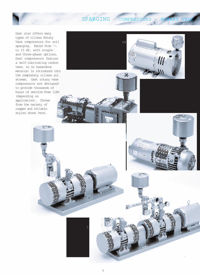
Model 0823
Top view
Side view
NOTICE: Overall length dimensions arereference only, due to optional motorsizes available
(mm) (inches)
SPARGING– COMPRESSORS – ROTARY VANE
9
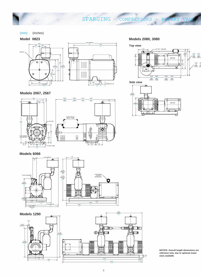
Gast Regenair ® regenerative high pressure blowersprovide an option to positive displacement pumps forsparging applications. These blowers developpressures comparable to rotary lobe-type pumpswhile delivering long life and maintenance-freeoperation.
*Reduce maximum duty ratings by approx. 0.5 psig when operating at 207-187 volts (60 Hz)
(mm) (inches)
0
2
4
6
8
10
12
0 20 40 60 80 100 120 140
FREE AIR FLOW (cfm)
60Hz
50Hz
mbar0
800
300
100
200
400
500
600
700
m3/h
120 2400 2001608040
PRESSURE R4H3060A, R4H3060B
0
50
100
150
200
0 1 2 3 4 5 6
PRESSURE (psig)
60Hz
50Hz
R4M3090AAir Temp. Rise over Ambient vs. Pressure
°C0
93
10
38
41
mbar
200 4000 300100
0
50
100
150
200
250
0 2 4 6 8 10 12
PRESSURE (psig)
60Hz
50Hz
R4H3060A, R4H3060BAir Temp. Rise over Ambient vs. Pressure
mbar
400 8000 600200
°C0
121
10
38
93
41
0
1
2
3
4
5
6
7
0 40 80 120 160 200 240 280
FREE AIR FLOW (cfm)
60Hz
50Hz
PRESSURE R4M3090A
mbar
0
450
50
200
100
150
250
300
400
350
500
m3/h450150 300 4000 35025020010050
Product SpecificationsModel Motor Specifications Max Pressure Max Flow Net. Wt.Number Phase Hz Voltages HP Full Load Amps psig mbar cfm m 3h lbs kg
R4H3060A Three 60 208-230/460 6 19.5-18.2/9.1 10.25 707 128 217 200 9150 190-220/380-440 5 16.8-16.0/8.4-8.0 10 690 107 182
R4H3060B Three 60 575 6 7.3 10.25 707 128 217 200 91
R4M3090A Three 60 208-230/460 9 24-22.2/11.1 6.1 421 252 428 198 9050 190-220/380-440 7 19.8-18.5/9.9-9.3 5.4 372 217 369
SPARGING– COMPRESSORS– REGENERATIVE BLOWERS

10
The separator removesliquids from the gasstream in a soil vaporextraction process, tohelp protect bothblower and vaportreatment system fromcorrosion and mineraldeposit buildup. Theseparator is locatedbetween the extractionwells and the blower. Anin-line filter isinstalled betweenseparator and blower.
RELIEF VALVESHIPPEDUNATTACHED
APPROX.
APPROX.
3/4" NPT
VALVE
NIPPLE & VALVESHIPPEDUNATTACHED
NPT
REF.
REF.
0
4
8
12
16
0 100 200 300 400
FLOW (cfm)
RMS 200
RMS 160
RMS 300
RMS 400
m3/h
0
40
8
24
mbar
32
16
0 680136 408 544272
RESTRICTION VS. FLOW
Cut away to show ball float. Abovemodel shows optional explosion
proof float switch AJ213
Part No. Liq. Cap. (gal.) A(dia.) Dim. B C(NPT) D(dia.) Dim. E Dim. FRMS160 10 14.8" 37.5" 2" 2" 7.5" 26.6"RMS200 19 19.7" 35" 2" 2" 7.5" 26.6"RMS300 19 19.7" 35" 2.5" 2.5" 7.5" 26.6"RMS400 40 24" 44" 3" 3" 9.7" 29"
Regenair ® Liquid Separator Specifications
Practical Design Engineered to remove and containmoisture ranging from a fine mist to slugs of waterfrom blower inlet air streams, Gast separatorsincorporate a cyclonic action which results in avery high degree of efficiency. A floating ball valve which closes when the liquidlevel becomes too high prevents collected liquidfrom overflowing back into the air stream. Whenthe float valve closes an integral vacuum reliefvalve opens, admitting air to cool the blower andprevent overheating.
Rugged Construction Gast separator drums are madefrom ribbed heavy gauge cold-rolled steel, withheavy steel inlet, drain and float switch ports weldedto the drum wall. Drum interiors are epoxy coated toresist abrasion, corrosion and chemicals, while thedrum exterior is coated with durable urethane. Forease of connection, the outlet port is female pipethreaded. The heavy-duty 304 stainless steel ballfloat resists chemicals; maximum rated vacuum is22 inches Hg (299 inches H 20).
Included is a pilot operated precision relief valvecapable of functioning over a wide duty range. Thisvacuum relief valve is designed and built to provenreliability and durability standards. Moving partsare nickelplated for corrosion resistance andsmooth operation. Explosion proof AJ213 floatswitch is optional; single pole double throw switch;electrical rating 5 amps at 125/250 VAC.
LIQUID SEPARATOR

11
RELIEF VALVESHIPPEDUNATTACHED
APPROX.
APPROX.
3/4" NPT
VALVE
NIPPLE & VALVESHIPPEDUNATTACHED
NPT
REF.
REF.
Part No. Liq. Cap. (gal.) A(dia.) Dim. B C(NPT) D(dia.) Dim. E Dim. FRMS160 10 14.8" 37.5" 2" 2" 7.5" 26.6"RMS200 19 19.7" 35" 2" 2" 7.5" 26.6"RMS300 19 19.7" 35" 2.5" 2.5" 7.5" 26.6"RMS400 40 24" 44" 3" 3" 9.7" 29"
Part No. Dim. A Dim. B Dim. C Dim. D Dim. EAJ151C 7.38" 6.81" 4.62" 1-1/4" FPT 1-1/4" FPTAJ151D 7.38" 6.81" 4.62" 1-1/2" FPT 1-1/2" FPTAJ151E 8.75" 10.25" 5.00" 2" FPT 2" FPTAJ151G 8.00" 10.25" 5.50" 2-1/2" FPT 2-1/2" FPTAJ151H 14.00" 26.50" 18.13" 3" MPT 3" MPTAJ151L 14.00" 27.13" 18.50" 4" MPT 4" MPT
Part No. Dim. A Dim. B Dim. CAJ126C 6.00" 7.12" 1-1/4" MPTAJ126D 7.70" 7.25" 1-1/2" MPTAJ126F 10.63" 4.81" 2" FPTAJ126G 10.00" 13.12" 2-1/2" MPTAJ126L 10.00" 14.62" 4" MPT
Liquid SeparatorsSeparators remove liquids from the gas stream in a vacuum process, helping protectthe blower from corrosion and a buildup of mineral deposits.
FiltersSince the blower impeller passes very close to the housing, it is always wise to havean in-line or inlet filter to ensure trouble free life.
In-line (for vacuum)
Inlet (for pressure units only) A
B
C
MPT = Male Pipe Thread FPT = Female Pipe Thread All are heavy-duty for high amounts of particulates.Inlet filters for REGENAIR® blowers are drip-proof when mounted as shown.
Part No. Product Type Description Used OnRMS160 Liquid separator 10 gallon liquid carrying capacity R3, R4, R4P, R5 BlowersRMS200 Liquid separator 19 gallon liquid carrying capacity R4, R4P, R5, R6 BlowersRMS300 Liquid separator 19 gallon liquid carrying capacity R5, R6, R6P BlowersRMS400 Liquid separator 40 gallon liquid carrying capacity R6P, R7 BlowersAJ213 Float switch SPDT switch, 5 amp 125/250 VAC, 1" NPT mounting RMS Series-Separators
For Vacuum ServiceAJ151C In-line filter 10 micron filter (replacement element AJ135E) R3 BlowerAJ151D In-line filter 10 micron filter (replacement element AJ135E) R4, R4PAJ151E In-line filter 10 micron filter (replacement element AJ135F) R5, R4H BlowersAJ151G In-line filter 10 micron filter (replacement element AJ135G) R6, R6P, R4M BlowersAJ151H In-line filter 10 micron filter (replacement element AJ135C) R7 Blower
For CompressorÐInletAJ126C Inlet filter 10 micron filter (replacement element AJ134C) R3 Blower, 2067, 2567AJ126D Inlet filter 10 micron filter (replacement element AJ134E) 80 Series, 6066, 1290, R4, R4H
R4P, R5 BlowersAJ126F Inlet filter 25 micron filter (replacement element AG340) R6, R6P, R4M BlowersAJ126G Inlet filter 10 micron filter (replacement element AJ135A) R7 BlowerAL355 Inlet filter 10 micron filter 0823
MPT = Male Pipe Thread FPT = Female Pipe Thread All are heavy-duty for high amounts of particulates.Inlet filters for REGENAIR® blowers are drip-proof when mounted as shown.
ACCESSORIES
12
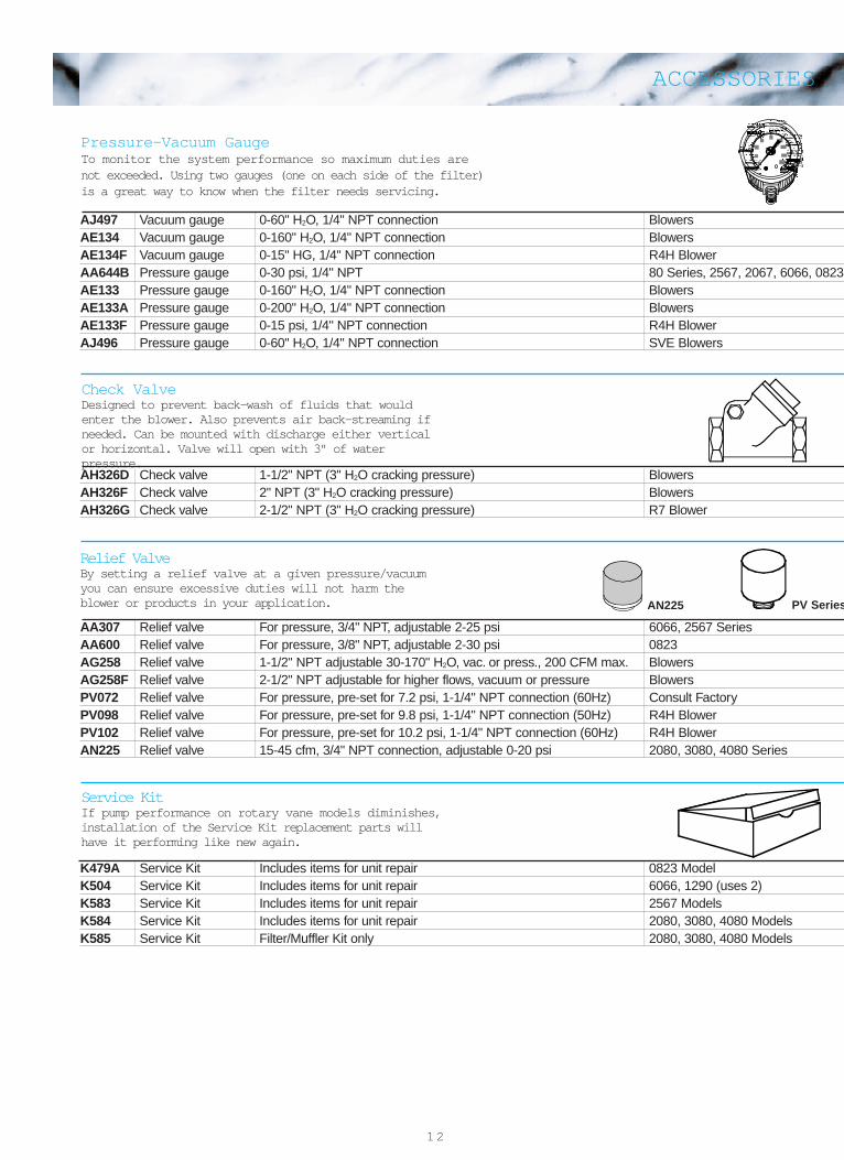
Pressure-Vacuum GaugeTo monitor the system performance so maximum duties arenot exceeded. Using two gauges (one on each side of the filter)is a great way to know when the filter needs servicing.
Relief ValveBy setting a relief valve at a given pressure/vacuumyou can ensure excessive duties will not harm theblower or products in your application.
Check ValveDesigned to prevent back-wash of fluids that wouldenter the blower. Also prevents air back-streaming ifneeded. Can be mounted with discharge either verticalor horizontal. Valve will open with 3" of waterpressure.
Service KitIf pump performance on rotary vane models diminishes,installation of the Service Kit replacement parts willhave it performing like new again.
AN225 PV Series
AJ497 Vacuum gauge 0-60" H2O, 1/4" NPT connection BlowersAE134 Vacuum gauge 0-160" H2O, 1/4" NPT connection BlowersAE134F Vacuum gauge 0-15" HG, 1/4" NPT connection R4H BlowerAA644B Pressure gauge 0-30 psi, 1/4" NPT 80 Series, 2567, 2067, 6066, 0823AE133 Pressure gauge 0-160" H2O, 1/4" NPT connection BlowersAE133A Pressure gauge 0-200" H2O, 1/4" NPT connection BlowersAE133F Pressure gauge 0-15 psi, 1/4" NPT connection R4H BlowerAJ496 Pressure gauge 0-60" H2O, 1/4" NPT connection SVE Blowers
AH326D Check valve 1-1/2" NPT (3" H2O cracking pressure) BlowersAH326F Check valve 2" NPT (3" H2O cracking pressure) BlowersAH326G Check valve 2-1/2" NPT (3" H2O cracking pressure) R7 Blower
K479A Service Kit Includes items for unit repair 0823 ModelK504 Service Kit Includes items for unit repair 6066, 1290 (uses 2)K583 Service Kit Includes items for unit repair 2567 ModelsK584 Service Kit Includes items for unit repair 2080, 3080, 4080 ModelsK585 Service Kit Filter/Muffler Kit only 2080, 3080, 4080 Models
AA307 Relief valve For pressure, 3/4" NPT, adjustable 2-25 psi 6066, 2567 SeriesAA600 Relief valve For pressure, 3/8" NPT, adjustable 2-30 psi 0823AG258 Relief valve 1-1/2" NPT adjustable 30-170" H2O, vac. or press., 200 CFM max. BlowersAG258F Relief valve 2-1/2" NPT adjustable for higher flows, vacuum or pressure BlowersPV072 Relief valve For pressure, pre-set for 7.2 psi, 1-1/4" NPT connection (60Hz) Consult FactoryPV098 Relief valve For pressure, pre-set for 9.8 psi, 1-1/4" NPT connection (50Hz) R4H BlowerPV102 Relief valve For pressure, pre-set for 10.2 psi, 1-1/4" NPT connection (60Hz) R4H BlowerAN225 Relief valve 15-45 cfm, 3/4" NPT connection, adjustable 0-20 psi 2080, 3080, 4080 Series
ACCESSORIES

13
Friction causes pressure loss in all systems. Plumbing design and length affect this loss in air flow.
1. Determine total straight pipe equivalent.List number of each fitting in system. Circle the column under the supply pipe size. Multiply the numberof each item by the pipe size conversion factor to find the equivalent amount of straight pipe. Addequivalent figures to actual straight pipe figures.
2. Determine total friction loss in pipe system.On bottom line of the pipe friction loss chart, mark the air flow needed. Using a ruler, scan verticallyfrom the CFM figure to the diagonal line for the proper pipe size. Mark the intersection and then scan tothe left (vertical) axis to find the friction loss figure.
3. Divide the Total straight pipe equivalent from step 1 by 10; multiply by friction loss figure justdetermined to get the total friction loss in the pipe system.
_________________ ÷ 10 x _________________ = _______________________
Friction loss in pipe fittings equivalent length of straight pipe
Fitting # 3/4" 1" 1-1/4" 1-1/2" 2" 2-1/2" 3" 4" Equivalent Feet
90° Elbows ___x 2.0 3.0 3.5 4.0 5.0 6.0 8.0 10.0 =_____
Std. through tees ___x 1.5 2.0 2.5 3.0 3.5 4.0 5.0 7.0 =_____
Std. branch tees ___x 4.0 5.0 7.0 8.0 10.5 12.5 15.5 20.0 =_____
Check valves ___x 7.0 9.0 11.5 13.5 17.0 20.5 25.5 34.0 =_____
Gate valves ___x 0.55 0.7 0.9 1.0 1.5 2.0 2.0 3.0 =_____
Total length of straight pipe =_____ft.
Total straight pipe equivalent =_____ft.
Total feet of pipein system
Friction loss factor Total friction lossin system in H 2O"
CALCULATING SYSTEM FRICTION LOSS

14
PRESSURE CONVERSION TABLELbs. Per Atmospheres Inches of Millimeters Inches of Meters of Milli KilopascalsSq. Inch Mercury of Mercury Water Water Bars
1 .0680 2.036 51.71 27.73 .7037 69.0 6.89514.70 1 29.92 760 407 10.33 1013.3 101.36.4912 .0334 1 25.4 13.6 .3452 33.86 3.387.0193 .001315 .03937 1 .5358 .0136 1.33 .13307.0361 .00246 .0735 1.868 1 .0254 2.49 .248911.422 .0967 2.895 73.55 39.37 1 97.98 9.804714.50 .0009869 .02953 .750 .4018 .01021 1 .09998.145 .00986 .29529 7.4996 4.0174 .10206 10.01 1
VOLUME FLOW CONVERSION TABLEcfm cfh gpm m 3h l/s
1 60 7.4805 1.6990 .471951/60 1 .12468 .02832 .007866.13368 8.0208 1 .22712 .06309.58858 35.315 4.4029 1 1/3.62.1189 127.13 15.850 3.6 1
Power and Heat Flow Conversion Tablehp(U.S.) ft.lb/min Btu/hr Btu/min W kcal/min
1 33000 2544.4 42.407 745.70 10.686.000030303 1 .07710 .001285 .02260 .0003238.0003930 12.969 1 1/60 .29307 .004200.02358 778.17 60 1 17.584 .25200.00134 44.254 3.4121 .05687 1 .01433.09358 3088.0 238.10 3.9683 69.780 1
Temperature Conversion Chart¡C = 5Ú9 (¡F -32) ¡F = (9Ú5¡C) +32 TABLE EXAMPLE:Absolute Kelvin = ¡C +273.15 Rankine ¡F = +459.67 To Convert 100 ¡C to ¡F look up 100 read left
To Convert 100 ¡F to ¡C look up to 100 read right
to ¡F From to ¡C-148.0 -100 -73.33-130.0 -90 -67.78-112.0 -80 -62.22-94.0 -70 -56.67-76.0 -60 -51.11-58.0 -50 -45.56-40.0 -40 -40.00-36.4 -38 -38.89-32.8 -36 -37.78-29.2 -34 -36.67-25.6 -32 -35.56-22.0 -30 -34.44-18.4 -28 -33.33-14.8 -26 -32.22-11.2 -24 -31.11-7.6 -22 -30.00-4.0 -20 -28.89-0.4 -18 -27.78+3.2 -16 -26.67+6.8 -14 -25.56
+10.4 -12 -24.44+14.0 -10 -23.33+17.6 -8 -22.22+21.2 -6 -21.11+24.8 -4 -20.00+28.4 -2 -18.89+32.0 0 -17.78+35.6 +2 -16.67+39.2 +4 -15.56+42.8 +6 -14.44+46.4 +8 -13.33
to ¡F From to ¡C+50.00 +10 -12.22+53.6 +12 -11.11+57.2 +14 -10.00+60.8 +16 -8.89+64.4 +18 -7.78+68.0 +20 -6.67+71.6 +22 -5.56+75.2 +24 -4.44+78.8 +26 -3.33+82.4 +28 -2.22+86.0 +30 -1.11+89.6 +32 0.00+93.2 +34 +1.11+96.8 +36 +2.22
+100.4 +38 +3.33+104.0 +40 +4.44107.6 42 5.56111.2 44 6.67114.2 46 7.78118.4 48 8.89122.0 50 10.00125.6 52 11.11129.2 54 12.22132.8 56 13.33136.4 58 14.44140.0 60 15.56143.6 62 16.67147.2 64 17.78150.8 66 18.89154.4 68 20.00158.0 70 21.11
to ¡F From to ¡C161.6 72 22.22165.2 74 23.33168.8 76 24.44172.4 78 25.56176.0 80 26.67179.6 82 27.78183.2 84 28.89186.8 86 30.00190.4 88 31.11194.0 90 32.22197.6 92 33.33201.2 94 34.44204.8 96 35.56208.4 98 36.67212.0 100 37.78230.0 110 43.33248.0 120 48.89266.0 130 54.44284.0 140 60.00302.0 150 65.56320.0 160 71.11338.0 170 76.67356.0 180 82.22374.0 190 87.78392.0 200 93.33410.0 210 98.89428.0 220 104.44446.0 230 110.00464.0 240 115.56482.0 250 121.11
CONVERSION CHARTS

15
Piston Compressors andVacuum PumpsOilless, motor-mounted,and separate-drivemodels. Pressures to125 psig; up to 11 cfmfree air. Vacuums to28.5" Hg; up to 10.5cfm free air.
Air PoweredGearmotorsIn-line and right-anglemodels. Up to 5200-lb.-inch gear ratios from10:1 to 60:1 single reduction reducers.
The Designer’s Air SourceRecognized around the world as a leader in the manufacture of fractional horsepower air-moving products, weproduce over 100 basic models of quality pumps designed and built to meet the changing needs of industry.
ISO 9001 & 14001 CERTIFIED
Piston Compressors andVacuum PumpsOilless, motor-mounted,and separate-drivemodels. Pressures to125 psig; up to 11 cfmfree air. Vacuums to28.5" Hg; up to 10.5cfm free air.
Air PoweredGearmotorsIn-line and right-anglemodels. Up to 5200-lb.-inch gear ratios from10:1 to 60:1 single reduction reducers.
VacuumGeneratorsOilless, single- or multi-stage designs in chemical and corrosion-resistantmaterial. Vacuums to27" Hg, flow rates from0.2 to 158 cfm. Vacuumcups available also.
Rocking PistonCompressors andVacuum PumpsOilless, motor-mounted,mini, standard, and twinmodels. Pressures to175 psig; up to 5.5 cfmfree air. Vacuums to 29" Hg.
Oilless LinearCompressors andVacuum PumpsPerformance rangesfrom 11 to 252 lpm (0.39 to 8.9 cfm), withpressures to 10.5 psig (0,72 bar) and vacuum levels to 12.1" Hg (603 mbar).
Rotary VaneCompressors and VacuumPumpsOilless or lubricated.Motor-mounted orseparate-drive models.Open flows to 55 cfmfree air. Pressures to 25 psig, vacuums to28" Hg. Dual functionmodels available also.
Air MotorsSeven basic models from0.22 hp to 9.5 hp; choiceof five mountings; hub,foot, face, NEMA C-flange,and metric D seriesinterface. Rotation optionsinclude clockwise, counter-clockwise and reversible.Four-vane and eight-vanemodels available. Non-lubricated series up to 3⁄4 hp available also.
RegenerativeBlowersOilless, motor-mounted,and separate-drivemodels. Twin-endedmodels available. Pressures to 284" H2Oand vacuums to 184"H2O; 1350 cfm free air.Special models availablefor soil vapor extraction applications.
DiaphragmCompressors andVacuum PumpsOilless, motor-mounted,mini, standard, and twin models. Pressuresto 60 psig; up to 3.8 cfmfree air. Vacuums to 29" Hg; up to 3.6 cfmfree air.
Smart Air ™
TechnologyConcepts and productsthat marry electronics to pneumatics to achieveperformance improve-ments in pneumatic systems.