
224R_90
80
+)))))))))))))))))))))))))))))))))))))))))))))))))))))))))))))))))))))), * MCP Application Notes: * * * * 1. Character(s) preceded & followed by these symbols (. -) or (+ ,) * * are super- or subscripted, respectively. * * EXAMPLES: 42m.3- = 42 cubic meters * * CO+2, = carbon dioxide * * * * 2. All table notes (letters and numbers) have been enclosed in square* * brackets in both the table and below the table. The same is * * true for footnotes. * .))))))))))))))))))))))))))))))))))))))))))))))))))))))))))))))))))))))-
-
Upload
michael-ryan -
Category
Documents
-
view
17 -
download
5
Transcript of 224R_90

+)))))))))))))))))))))))))))))))))))))))))))))))))))))))))))))))))))))), * MCP Application Notes: * * * * 1. Character(s) preceded & followed by these symbols (. -) or (+ ,) * * are super- or subscripted, respectively. * * EXAMPLES: 42m.3- = 42 cubic meters * * CO+2, = carbon dioxide * * * * 2. All table notes (letters and numbers) have been enclosed in square* * brackets in both the table and below the table. The same is * * true for footnotes. * .))))))))))))))))))))))))))))))))))))))))))))))))))))))))))))))))))))))-

ACI 224R-90
Control of Cracking in Concrete Structures
Reported by ACI Committee 224
The principal causes of cracking in concrete and recommendedcrack control procedures are presented. The current state ofknowledge in microcracking and fracture mechanics is discussed.The control of cracking due to drying shrinkage and crack controlfor flexural members, layered systems and mass concrete arecovered in detail. Long-term effects on cracking are considered,and crack control procedures used in construction are presented.Information is provided to assist the engineer and theconstructor in developing practical and effective crack controlprograms for concrete structures.
Keywords: adiabatic conditions; aggregates; air entrainment;anchorage (structural); beams (supports); bridge decks;cement-aggregate reactions; cement content; cement types;compressive strength; computers; concrete construction; concretepavements; concrete slabs; concretes; conductivity;consolidation; cooling; crack propagation; cracking (fracturing);crack width and spacing; creep properties; diffusivity; dryingshrinkage; end blocks; expansive cement concretes; extensibility;failure; fibers; heat of hydration; insulation; joints(junctions); machine bases; mass concrete; microcracking; mixproportioning; modulus of elasticity; moisture content; Poissonratio; polymer-portland cement concrete; pozzolans; prestressedconcrete; reinforced concrete; reinforcing steels; restraints;shrinkage; specifications; specific heat; strain gages; strains;stresses; structural design; temperature; temperature rise (inconcrete); tensile stress; tension; thermal expansion; volumechange.
This document has been approved for use by agencies of theDepartment of Defense and for listing in the DoD Index ofSpecifications and Standards.
This report was submitted to letter ballot of the committeewhich consists of 24 members; 21 were affirmative, 2 were notreturned, and 1 abstained. It has been processed in accordancewith the Institute procedure and is approved for publication anddiscussion.
Copyright (C) 1980 and 1985, American Concrete Institute.
All rights reserved including rights of reproduction and use inany form or by any means, including the making of copies by anyphoto process, or by any electronic or mechanical device, printedor written or oral, or recording for sound or visual reproductionor for use in any knowledge or retrieval system or device, unlesspermission in writing is obtained from the copyright proprietors.
ACI Committee Reports Guides Standard Practices and Commentaries

are intended for guidance in designing, planning, executing, orinspecting construction and in preparing specifications.Reference to these documents shall not be made in the ProjectDocuments. If items found in these documents are desired to bepart of the Project Documents, they should be phrased inmandatory language and incorporated into the Project Documents.
Contents
Chapter 1--Introduction
Chapter 2--Crack mechanisms in concrete
2.1--Introduction 2.2--Microcracking 2.3--Fracture
Chapter 3--Control of cracking due to drying shrinkage
3.1--Introduction 3.2--Crack formation 3.3--Drying shrinkage 3.4--Factors influencing drying shrinkage 3.5--Control of shrinkage cracking 3.6--Shrinkage-compensating concretes
Chapter 4--Control of cracking in flexural members
4.1--Introduction 4.2--Crack control equations for reinforced concrete beams 4.3--Crack control in two-way slabs and plates 4.4--Tolerable crack widths versus exposure conditions in reinforced concrete 4.5--Flexural cracking in prestressed concrete 4.6--Anchorage zone cracking in prestressed concrete 4.7--Tension cracking
Chapter 5--Long-term effects on cracking
5.1--Introduction 5.2--Effects of long-term loading 5.3--Environmental effects 5.4--Aggregate and other effects 5.5--Use of polymers in improving cracking characteristics Chapter 6--Control of cracking in concrete layered systems
6.1--Introduction 6.2--Fiber reinforced concrete (FRC) overlays 6.3--Latex modified concrete (LMC) overlays 6.4--Polymer impregnated concrete (PIC) systems
Chapter 7--Control of cracking in mass concrete
7.1--Introduction 7.2--Crack resistance 7.3--Determination of temperatures and tensile strains 7.4--Control of cracking 7.5--Testing methods and typical data

7.6--Artificial cooling by embedded pipe systems 7.7--Summary--Basic considerations for construction controls and specifications
Chapter 8--Control of cracking by correct construction practices
8.1--Introduction 8.2--Restraint 8.3--Shrinkage 8.4--Settlement 8.5--Construction 8.6--Specifications to minimize drying shrinkage 8.7--Conclusion
Chapter 9--References
9.1--Specified and/or recommended references 9.2--Cited references
CHAPTER 1--INTRODUCTION
Cracks in concrete structures can indicate major structuralproblems and can mar the appearance of monolithic construction.They can expose reinforcing steel to oxygen and moisture and makethe steel more susceptible to corrosion. While the specificcauses of cracking are manifold, cracks are normally caused bystresses that develop in concrete due to the restraint ofvolumetric change or to loads which are applied to the structure.Within each of these categories there are a number of factors atwork. A successful crack control program must recognize thesefactors and deal with each of them, in turn. This report presents the principal causes of cracking and adetailed discussion of crack control procedures. The body of thereport consists of seven chapters designed to help the engineerand the contractor in the development of effective crack controlmeasures.
This report is an update of a previous committee report, issuedin 1972.[1.1] The original report was supplemented by an ACIBibliography on cracking,[1.2] also issued by this committee. Inthe updating process, many portions of the report have undergonesizeable revision, and the entire document has been subjected toa detailed editorial review. Chapter 2, on crack mechanisms, hasbeen completely rewritten to take into account the experimentaland analytical work that has been done since the completion ofthe first committee report. Chapter 6, on crack control inconcrete layered systems, is new to the report and deals with aform of concrete construction that was in its infancy at the timethe first report was drafted. Individual chapters on crackcontrol in reinforced and prestressed concrete members have beencondensed into a single chapter, Chapter 4, on crack control inflexural members. The resulting presentation is more concise and,hopefully, more useful to the structural designer. Chapter 5, onlong-term effects, details some interesting findings on thechange of crack width with time. Chapters 3, 7, and 8, whichconsider drying shrinkage, mass concrete, and constructionpractices, respectively, have been expanded and updated to takeinto account the most recently developed procedures in these

areas. In addition, new sections have been added to Chapters 7and 8 which provide specific guidance for the development ofcrack control programs and specifications.
The committee hopes that this report will serve as a usefulreference to the causes of cracking and as a key tool in thedevelopment of practical crack control procedures in both thedesign and the construction of concrete structures.
References
[1.1] ACI Committee 224, "Control of Cracking in ConcreteStructures." ACI JOURNAL, Proceedings V. 69, No. 12, Dec. 1972,pp. 717-753.
[1.2] ACI Committee 224, "Causes, Mechanism, and Control ofCracking in Concrete," ACI Bibliography No. 9, American ConcreteInstitute, Detroit, 1971, 92 pp.
CHAPTER 2--CRACK MECHANISMS IN CONCRETE*
(* Principal author: David Darwin.)
2.1--Introduction
Beginning with the work at Cornell University in the early1960s,[2.1] a great deal has been learned about the crackmechanisms in concrete, both at the microscopic and themacroscopic level. Of special interest during the early work wasthe realization that the behavior of concrete, under compressiveas well as tensile loads, was closely related to the formation ofcracks. Under increasing compressive stress, microscopic cracks(or microcracks) form at the mortar-coarse aggregate boundary andpropagate through the surrounding mortar, as shown in Fig. 2.1.

* From S. P. Shah, and F. O. Slate, "Internal Microcracking, Mortar-Aggregate Bond and the Stress- Strain Curve of Concrete," Proceedings, International Conference on the Structure of Concrete (London, Sept. 1965), Cement and Concrete Association, London, 1968, pp. 82-92.], p. 3
During the first decade of research, a picture developed thatclosely linked formation and propagation of these microcracks tothe load-deformation behavior of concrete. Prior to load, volumechanges in cement paste cause interfacial cracks to form at themortar-coarse aggregate boundary.[2.2,2.3] Under short-termcompressive load, no additional cracks form until the loadreaches approximately 30 percent of the compressive strength ofthe concrete.[2.1] Above this value, additional bond cracksinitiate throughout the matrix. Bond cracking increases until theload reaches approximately 70 percent of the compressivestrength, at which time microcracks begin to propagate throughthe mortar. Mortar cracking continues at an accelerated rateuntil the material ultimately fails. For concrete in uniaxialtension, experimental work indicates that major microcrackingbegins at about 60 percent of the ultimate tensile strength.[2.4]
Studies of the stress-strain behavior and volume change ofconcrete[2.5] indicate that the initiation of major mortarcracking corresponds with an observed increase in the Poisson'sratio of concrete. The term "discontinuity stress" is used forthe stress at which this change in material behavior occurs.
In general, it has been agreed that the microcracking thatoccurs prior to loading has very little effect on the strength ofconcrete. However, work by Brooks and Neville[2.6] indicates thatthe effect of early volume change on microcracking of concretemay result in a reduction of both tensile and compressivestrength as concrete dries out. Their study shows that upondrying, the strength of test specimens first increases and thendecreases. They postulate that the initial increase is due to theincreased strength of the drier cement paste and that theultimate decrease in strength is due to the formation ofshrinkage induced microcracks.
Work by Meyers, Slate, and Winter[2.7] and Shah andChandra[2.8] demonstrates that microcracks increase under theeffect of sustained and cyclic loading. Their work indicates thatthe total amount of microcracking is a function of the totalcompressive strain in the concrete and is independent of themethod in which the strain is applied. Sturman, Shah, andWinter[2.9] found that the total degree of microcracking isdecreased and the total strain capacity in compression isincreased when concrete is subjected to a strain gradient.
At about the same time that the microcracking studies began,investigators began applying fracture mechanics to the studies ofconcrete under load. The field of fracture mechanics, originatedby Griffith[2.10] in 1920, serves as the primary tool for thestudy of brittle fracture and fatigue in metal structures. Sinceconcrete has for many years been considered a brittle material intension, fracture mechanics is considered to be a potentiallyuseful analysis tool for concrete by many investigators.[2.11-2.24]

The field of fracture mechanics was first applied to concreteby Kaplan[2.11] in 1961. The classical theory serves to predictthe rapid propagation of a macrocrack through a homogeneous,isotropic, elastic material. The theory makes use of the stressintensity factor, K+l,, which is a function of crack geometry andstress. Failure occurs when K+l, reaches a critical value, K+lc,,known as the critical stress-intensity factor under conditions ofplane strain. K+lc, is thus a measure of the fracture toughnessof the material. To properly measure K+lc, for a material, thetest specimen must be of sufficient size to insure maximumconstraint (plane strain) at the tip of the crack. For linearelastic fracture mechanics (LEFM) to be applicable, the value ofK+lc, must be a material constant, independent of the specimengeometry (as are other material constants such as yieldstrength).
The earliest experimental work utilized notched tension andbeam specimens of mortar and concrete.[2.11-2.14] The crackresistance was expressed in terms of the strain energy releaserate at the onset of rapid crack growth, G, which is directlyrelated to the fracture toughness of the material. Laterinvestigations evaluated the crack resistance of paste, mortarand concrete in terms of the fracture toughness, itself.[2.15]Work by Naus and Lott[2.16] indicated that the fracture toughnessof paste and mortar increased with decreasing water-cement ratio,but that the water-cement ratio had little effect on the fracturetoughness of concrete. They found that K+lc, increased with age,and decreased with increasing air content for paste, mortar, andconcrete. The effective fracture toughness of mortar increasedwith increasing sand content, and the fracture toughness ofconcrete increased with an increase in the maximum size of coarseaggregate.
Additional work by Naus,[2.17] presented just prior to theprevious committee report,[1.1] indicated that fracture toughnesswas not independent of specimen geometry for tensile specimens ofpaste, mortar and concrete and that fracture toughness was afunction of the crack length. These observations lead to thepossibly erroneous conclusion that fracture mechanics may not beapplicable to concrete. Because certain size requirements must bemet, before fracture mechanics is applicable, these results mayonly indicate that the test specimen did not satisfy all of theminimum size requirements of linear elastic fracture mechanics.
The balance of this chapter describes some of the more recentstudies of crack mechanisms in concrete and gives a somewhatdifferent picture from that presented in the previous committeereport.
2.2--Microcracking
Since the early work established the existence of bond andmortar cracks, it has been popular to attribute all of thenonlinearity of concrete to the formation of these microscopiccracks.[2.1,2.25,2.26] However, a cause and effect relationshiphas never been established.[2.27] Recent studies [2.28-2.32]indicate that the degree of microcracking might be better takenas an indication of the level of damage rather than as thecontrolling factor in the behavior of concrete.
While microcracks appear to have a dominant effect on the
volume change of concrete under load, the importance ofmicrocracking, at least as it has been discussed in the past,seems to be somewhat downgraded.
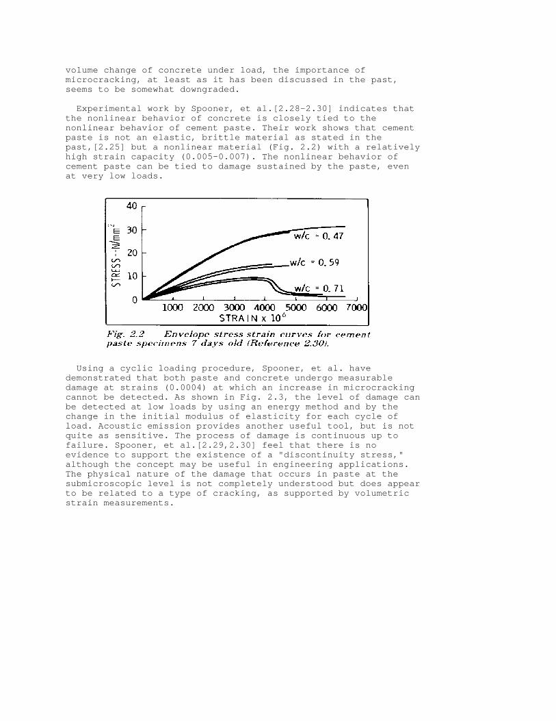
Experimental work by Spooner, et al.[2.28-2.30] indicates thatthe nonlinear behavior of concrete is closely tied to thenonlinear behavior of cement paste. Their work shows that cementpaste is not an elastic, brittle material as stated in thepast,[2.25] but a nonlinear material (Fig. 2.2) with a relativelyhigh strain capacity (0.005-0.007). The nonlinear behavior ofcement paste can be tied to damage sustained by the paste, evenat very low loads.
Using a cyclic loading procedure, Spooner, et al. havedemonstrated that both paste and concrete undergo measurabledamage at strains (0.0004) at which an increase in microcrackingcannot be detected. As shown in Fig. 2.3, the level of damage canbe detected at low loads by using an energy method and by thechange in the initial modulus of elasticity for each cycle ofload. Acoustic emission provides another useful tool, but is notquite as sensitive. The process of damage is continuous up tofailure. Spooner, et al.[2.29,2.30] feel that there is noevidence to support the existence of a "discontinuity stress,"although the concept may be useful in engineering applications.The physical nature of the damage that occurs in paste at thesubmicroscopic level is not completely understood but does appearto be related to a type of cracking, as supported by volumetricstrain measurements.

Studies of the stress-strain behavior of concrete under cycliccompressive load[2.8,2.33] indicate that concrete undergoes rapiddeterioration once the peak stress exceeds about 70 percent ofthe short-term ultimate strength of the concrete. Neville andHirst,[2.34] in their study of cyclic creep, found that even whenspecimens are cycled below this level, heat is given off. Theyattribute the heat to sliding at the interfacial boundary. Whencombined with the work of Spooner, however, in which he showsthat paste undergoes damage at very low loads, it may be possiblethat the heat measured is due to a submicroscopic sliding withinthe paste.
Several studies have attempted to establish the importance ofinterfacial bond strength on the behavior of concrete under load.Two studies[2.5,2.35] seemed to indicate a very large effect,thus emphasizing the importance of interfacial strength on thebehavior of concrete. These studies utilized relatively thick,soft coatings on the coarse aggregate to reduce the bondstrength. Since these soft coatings isolated the aggregate fromthe surrounding mortar, the effect was more like inducing a largenumber of voids in the concrete matrix.
Two other studies[2.36,2.37] which did not isolate the coarseaggregate from the mortar indicate that the interfacial strengthplays only a minor role in controlling the stress-strain behaviorand ultimate strength of concrete. Darwin and Slate[2.36] used athin coating of polystyrene on natural coarse aggregate. Theyfound that a large reduction in interfacial bond strength causesno change in the initial stiffness of concrete under short-termcompressive loads and results in approximately a 10 percentreduction in the compressive strength as compared to similarconcrete made with aggregate with normal interfacial strength(see Fig. 2.4). They also found that the lower interfacialstrength had no appreciable effect on the total amount ofmicrocracking. However, in every case, the average amount ofmortar cracking was slightly greater for the specimens made withcoated aggregate. This small yet consistent difference mayexplain the differences in the stress-strain curves.

Perry and Gillott[2.37] used glass spheres with differentdegrees of surface roughness as coarse aggregate. Their resultsindicate that reducing the interfacial strength of the aggregatedecreases the initiation stress by about 20 percent, but has verylittle effect on the discontinuity stress. They also observed a10 percent reduction in the compressive strength for specimenswith low mortar-aggregate bond strength.
Work by Carino,[2.38] using polymer impregnated concrete, seemsto corroborate these two studies. Carino found that polymerimpregnation did not increase the interfacial bond strength, butdid increase the compressive strength of concrete. He attributedthe increase in strength to the effect of the polymer on thestrength of mortar, thus downgrading the importance of theinterfacial bond.
The importance of mortar, and ultimately cement paste, incontrolling the stress-strain behavior of concrete is illustratedby the finite element work of Buyukozturk[2.39] and Maher andDarwin.[2.31,2.32] Using a linear finite element representationof a physical model of concrete, Buyukozturk was able to simulatethe overall crack patterns under uniaxial loading. However, hisfinite element model could not duplicate the nonlinearexperimental behavior of the physical model using the formationof interfacial bond cracks and mortar cracks as the onlynonlinear effect. Maher and Darwin[2.31,2.32] have shown that byusing a nonlinear representation for the mortar constituent ofthe physical model, a very close representation of the actualbehavior can be obtained. The results for Buyukozturk's model areshown in Fig. 2.5.

The inability of linear elastic models [2.25,2.26,2.39] toduplicate the nonlinear behavior of concrete utilizingmicrocracking alone has been explained as being due to the factthat concrete is really a "statistical material." When the properstatistical variation is selected, the nonlinear behavior ofconcrete can be duplicated.[2.25] While the statisticalvariations undoubtedly play a part, the major nonlinear behaviorcan also be matched by considering the nonlinearities of themortar constituent.[2.31,2.32] Fig. 2.6 illustrates the resultsobtained for a highly simplified model of concrete under uniaxialcompression using a nonlinear representation for mortar. Thestress-strain curve for the model without cracking differs verylittle from that of models that have a normal, or above normal,amount of microcracking. Microcracks have a relatively minoreffect on the primary stress-strain behavior of the models. Thedominant effect of microcracking is to increase the lateralstrain. In every case the failure of the model is governed by"crushing" of the mortar which occurs at an average strengthbelow that of the mortar alone.
Newman[2.5] and Tasuji, Slate, and Nilson[2.40] have observedthat the principal tensile strain in concrete at the"discontinuity stress" appears to be a function of the mean

normal stress, F+m, = (F+1, + F+2, + F+3,)/3. In their study ofthe biaxial strength of concrete, Tasuji, et al., observe thatthe final failure of their specimens consists of the formation ofmacroscopic tensile cracks. They also observe that the stress atdiscontinuity occurs at approximately 75 percent of the ultimatestrength in compression and at about 60 percent of the ultimatestrength for those cases involving tension, matching the levelsat which mortar cracking begins.[2.3,2.4] Their work seems topoint very strongly toward a "limiting tensile strain" as thegoverning factor in the strength of concrete.
Overall, the damage to cement paste seems to play an importantrole in controlling the primary stress-strain behavior ofconcrete under short-term axial load. In normal weight concrete,aggregate particles act as stress-raisers, increasing the initialstiffness and decreasing the strength of the paste. For cyclicand sustained loading, a great deal of the bond cracking resultsfrom load induced volume changes within the paste, but has nosignificant effect on strength. A number of investigators feelthat the onset of mortar cracking marks the "true" ultimatestrength of concrete.[2.6-2.8,2.33,2.34,2.41] Whether mortarcracking itself controls the strength of concrete or whether itonly signals intimate damage of the cement paste remains to beseen. Additional studies in this area are clearly warranted.
2.3--Fracture
Since the publication of the previous report, a number ofinvestigations have shed additional light on the applicability offracture mechanics to concrete and its constituent materials. Shah and McGarry utilized flexure specimens subjected tothree-point loading.[2.42] Their work indicates that while pasteis notch sensitive, neither mortar nor concrete are affected by anotch (Fig. 2.7). Shah and McGarry also ran a series of testsusing notched tensile specimens and determined that pastespecimens, and mortar specimens made with fine aggregate thatpassed the #30 sieve, are notch sensitive, but that mortarspecimens containing larger sizes of aggregate are not notchsensitive.

Brown utilized notched flexure specimens and double cantileverbeam specimens of paste and mortar.[2.18] His tests show that thefracture toughness of cement paste is independent of crack lengthand is therefore a material constant. The fracture toughness ofmortar, however, increases as the crack propagates, indicatingthat the addition of fine aggregate improves the toughness ofpaste. This behavior is similar to the behavior found instructural steels that exhibit a plane strain-plane stresstransition. Because the plane strain-plane stress transitionoccurs beyond the limits of LEFM, the analysis is more complex.To re-establish the applicability of LEFM, larger test specimensmust be used with tougher materials such as mortar.
Mindess and Nadeau investigated the effect of notch width onK+lc, for both mortar and concrete.[2.20] Utilizing notched beamspecimens of constant length and depth, with varying widths, theyfound that within the range studied, there was no dependence offracture toughness upon the length of crack front. Since theirwork utilized small specimens with a depth of only about 50 mm (2in.), there is some indication that rather than measuring thefracture toughness of the material, they were simply measuringthe modulus of rupture.
The applicability of these results, and much of the otherfracture mechanics work, has been brought into perspective basedon the experimental work by Walsh. In separate investigations ofnotched beam specimens[2.21] and beams with right anglere-entrant notches,[2.22] Walsh has demonstrated that specimensize has a marked influence on the applicability of linearelastic fracture mechanics to the failure of plain concretespecimens. As illustrated in Fig. 2.8, for specimens of similargeometry but below a certain critical size, the specimen capacityis governed by the modulus of rupture of concrete, calculatedfrom the linear stress distribution. For specimens above thissize, the strength is governed by the fracture toughness, whichhe approximated as a function of the square root of thecompressive strength of the concrete. Walsh concluded that, forvalid toughness testing of concrete, the depth of notched beamsmust be at least 230 mm (9 in.). This type of behavior is alsoobserved in metals, i.e., for valid fracture mechanics testresults, the test specimens must meet minimum size requirements(ASTM E 399). These size requirements are dependent upon thesquare of the toughness levels being measured. Thus a materialwhose toughness level is twice that of another material (allother properties being equal), must have specimen dimensions fourtimes that of the first material for the test results to beequally valid.

Gjorv, Sorensen and Arnesen[2.23] investigated the notchsensitivity of paste, mortar and concrete using three-point bendspecimens similar to those used by Shah and McGarry.[2.42] Asshown in Fig. 2.9, they determined that both mortar and concreteare notch sensitive, but less sensitive than cement paste. Theyconclude that the disagreement with the earlier results is due inpart to their improvement in the loading procedure. They feelthat linear elastic fracture mechanics is applicable to the smallspecimens of paste, but not to the small size specimens of mortarand concrete. Even the small specimens of mortar and concrete,however, have some degree of notch sensitivity since the failureis not consistent with the modulus of rupture based on the netcross section. Citing Walsh's earlier work,[2.21] they agree thatLEFM is applicable to large concrete specimens, but that it isnot applicable to small specimens.

Hillemeier and Hilsdorf[2.43] utilized wedge loaded, compacttension specimens to measure the fracture toughness of paste,aggregate and the paste-aggregate interface. They feel that,while the failure of concrete in tension and compression iscontrolled by many interacting cracks rather than by thepropagation of a single crack, fracture mechanics does offer animportant tool for evaluating the constituent materials ofconcrete. They found that paste is a notch sensitive material andthat the addition of entrained air or soft particles has only asmall affect on K+lc,. Their work indicates that the K+lc, valuesfor interfacial strength between paste and aggregate is onlyabout one-third of the K+lc, value for paste alone, and that thecharacteristic value of K+lc, for aggregate is approximately tentimes that of paste.
Swartz, Hu, and Jones[2.24] used compliance measurement tomonitor crack growth in notched concrete beams subjected tosinusoidal loading. They conclude that this procedure is usefulfor monitoring crack growth in concrete due to fatigue. Based onthe appearance of the fracture surface, which shows a combinationof both aggregate fracture and bond failure, they feel thatfracture toughness is not a pertinent material property. However,they state that an "effective" fracture toughness might be asignificant material property if related to specific material andspecimen variables such as aggregate size and gradation, andproportions of the mix, and if the calculation considers thenonlinear material response of concrete.
A number of investigators do not feel that the Griffith theoryof linear fracture mechanics is directly applicable to allconcretes[2.23,2.24,2.42] (ASTM E 399). Some like Swartz, etal.[2.24] feel that the theory has application when thelimitations and specific nonhomogeneous effects are taken intoaccount, Clearly, specimen size requirements must be given moreattention. Of key interest in future work are the observations byWalsh[2.21,2.22] that show that if the specimens are largeenough, the effects of heterogeneity are greatly reduced and thatconcrete may approximate a homogenous material to which theprinciples of fracture mechanics can be applied.
References
[2.1] Hsu, Thomas T. C.; Slate, Floyd O.; Sturman, Gerald M.;and Winter, George, "Microcracking of Plain Concrete and theShape of the Stress-Strain Curve," ACI JOURNAL, Proceedings V.60, No. 2, Feb. 1963, pp. 209-224.
[2.2] Hsu, Thomas, T. C., "Mathematical Analysis of ShrinkageStresses in a Model of Hardened Concrete," ACI JOURNAL,Proceedings V. 60, No. 3, Mar. 1963, pp. 371-390.
[2.3] Slate, Floyd O., and Matheus, Ramon E., "Volume Changeson Setting and Curing of Cement Paste and Concrete from Zero toSeven Days," ACI JOURNAL, Proceedings V. 64, No. 1, Jan. 1967,pp. 34-39.
[2.4] Evans, R. H., and Marathe, M. S., "Microcracking andStress-Strain Curves for Concrete in Tension," Materials andStructures, Research and Testing (Paris). V. 1, No. 1, Jan. 1968,pp. 61-64.

[2.5] Newman, Kenneth, "Criteria for the Behavior of PlainConcrete Under Complex States of Stress," Proceedings,International Conference on the Structure of Concrete (London,Sept. 1965), Cement and Concrete Association, London, 1968, pp.255-274.
[2.6] Brooks, J. J., and Neville, A. M., "A Comparison ofCreep, Elasticity and Strength of Concrete in Tension and inCompression," Magazine of Concrete Research (London), V. 29, No.100, Sept. 1977, pp. 131-141. [2.7] Meyers, Bernard L.; Slate, Floyd O.; and Winter, George,"Relationship Between Time-Dependent Deformation andMicrocracking of Plain Concrete," ACI JOURNAL, Proceedings V. 66,No. 1, Jan. 1969, pp. 60-68.
[2.8] Shah, Surendra P., and Chandra, Sushil, "Fracture ofConcrete Subjected to Cyclic and Sustained Loading," ACI JOURNAL,Proceedings V. 67, No. 10, Oct. 1970, pp. 816-824.
[2.9] Sturman, Gerald M.; Shah, Surendra P.; and Winter,George, "Effects of Flexural Strain Gradients on Microcrackingand Stress-Strain Behavior of Concrete," ACI JOURNAL, ProceedingsV. 62, No. 7, July 1965, pp. 805-822.
[2.10] Griffith, A. A., "The Phenomena of Rupture and Flow inSolids," Transactions, Royal Society of London, No. 221A, 1920,pp. 163-198.
[2.11] Kaplan, M. F., "Crack Propagation and the Fracture ofConcrete," ACI JOURNAL, Proceedings V. 58, No. 5, Nov. 1961, pp.591-610.
[2.12] Glucklich, Joseph, "Static and Fatigue Fractures ofPortland Cement Mortars in Flexure," Proceedings, FirstInternational Conference on Fracture, Sendai, Japan, V. 2, 1965,pp. 1343-1382.
[2.13] Romualdi, James P., and Batson, Gordon B., "Mechanics ofCrack Arrest in Concrete," Proceedings, ASCE, V. 89, EM3, June1963, pp. 147-168.
[2.14] Huang, T. S., "Crack Propagation Studies inMicroconcrete," MSc Thesis, Department of Civil Engineering,University of Colorado, Boulder, 1966.
[2.15] Lott, James L., and Kesler, Clyde E., "Crack Propagationin Plain Concrete," Symposium on Structure of Portland CementPaste and Concrete, Special Report No. 90, Highway ResearchBoard, Washington, D.C., 1966, pp. 204-218.
[2.16] Naus, Dan J., and Lott, James L., "Fracture Toughness ofPortland Cement Concretes," ACI JOURNAL, Proceedings V. 66, No.6, June 1969, pp. 481-489.
[2.17] Naus, Dan J., "Applicability of Linear-Elastic FractureMechanics to Portland Cement Concretes," PhD Thesis, Universityof Illinois, Urbana, Aug. 1971.
[2.18] Brown, J. H., "Measuring the Fracture Toughness ofCement Paste and Mortar," Magazine of Concrete Research (London),

V. 24, No. 81, Dec. 1972, pp. 185-196. [2.19] Evans, A. G.; Clifton, J. R.; and Anderson, E., "TheFracture Mechanics of Mortars," Cement and Concrete Research, V.6, No. 4. July 1976, pp. 535-547.
[2.20] Mindess, Sidney, and Nadeau, John S., "Effect of NotchWidth of K+lc, for Mortar and Concrete," Cement and ConcreteResearch, V. 6, No. 4, July 1976, pp. 529-534.
[2.21] Walsh, P. F., "Fracture of Plain Concrete," IndianConcrete Journal (Bombay), V. 46, No. 11, Nov. 1972, pp. 469-470,476.
[2.22] Walsh, P. F., "Crack Initiation in Plain Concrete,"Magazine of Concrete Research (London), V. 28, No. 94, Mar. 1976,pp. 37-41.
[2.23] Gjorv, O. E.; Sorensen, S. I.; and Arnesen, A., "NotchSensitivity and Fracture Toughness of Concrete," Cement andConcrete Research, V. 7, No. 3, May 1977, pp. 333-344.
[2.24] Swartz, Stuart E.; Hu, Kuo-Kuang; and Jones, Gary L.,"Compliance Monitoring of Crack Growth in Concrete," Proceedings,ASCE, V. 104, EM4, Aug. 1978, pp. 789-800.
[2.25] Shah, Surendra P., and Winter, George, "InelasticBehavior and Fracture of Concrete, ACI JOURNAL, Proceedings V.63, No. 9, Sept. 1966, pp. 925-930.
[2.26] Testa, Rene B., and Stubbs, Norris, "Bond Failure andInelastic Response of Concrete," Proceedings, ASCE, V. 103, EM2,Apr. 1977, pp. 296-310.
[2.27] Darwin, David, Discussion of "Bond Failure and InelasticResponse of Concrete," by Rene B. Testa and Norris Stubbs,Proceedings, ASCE, V. 104, EM2, Apr. 1978, pp. 507-509.
[2.28] Spooner, D. C., "The Stress-Strain Relationship forHardened Cement Pastes in Compression," Magazine of ConcreteResearch (London), V. 24, No. 79, June 1972, pp. 85-92.
[2.29] Spooner, D. C., and Dougill, J. W., "A QuantitativeAssessment of Damage Sustained in Concrete During CompressiveLoading," Magazine of Concrete Research (London), V. 27, No. 92,Sept. 1975, pp. 151-160.
[2.30] Spooner, D. C.; Pomeroy, C. D.; and Dougill, J. W.,"Damage and Energy Dissipation in Cement Pastes in Compression,"Magazine of Concrete Research (London), V. 28, No. 94, Mar. 1976,pp. 21-29.
[2.31] Maher, Ataullah, and Darwin, David, "A Finite ElementModel to Study the Microscopic Behavior of Plain Concrete," CRINCReport-SL-76-02, The University of Kansas Center for Research,Lawrence, Nov. 1976, 83 pp.
[2.32] Maher, Ataullah, and Darwin, David, "Microscopic FiniteElement Model of Concrete," Proceedings, First InternationalConference on Mathematical Modeling (St. Louis, Aug.-Sept. 1977),University of Missouri-Rolla, 1977, V. III, pp. 1705-1714.
[2.33] Karsan, I. Demir, and Jirsa, James O., "Behavior ofConcrete under Compressive Loadings," Proceedings, ASCE, V. 95,ST12, Dec. 1969, pp. 2543-2563.
[2.34] Neville, A. M., and Hirst, G. A., "Mechanism of CyclicCreep of Concrete," Douglas McHenry Symposium on Concrete andConcrete Structures, SP55, American Concrete Institute, Detroit,1978, pp. 83-101.
[2.35] Nepper-Christensen, Palle, and Nielsen, Tommy P. H.,"Modal Determination of the Effect of Bond Between CoarseAggregate and Mortar on the Compressive Strength of Concrete,"ACI JOURNAL, Proceedings V. 66, No. 1, Jan. 1969, pp. 69-72.
[2.36] Darwin, David, and Slate, F. O., "Effect ofPaste-Aggregate Bond Strength on Behavior Concrete, Journal ofMaterials, V. 5, No. 1, Mar. 1970, pp. 86-98.
[2.37] Perry, C., and Gillott, J. E., "The Influence ofMortar-Aggregate Bond Strength on the Behavior of Concrete inUniaxial Compression," Cement and Concrete Research, V. 7, No. 5,Sept. 1977, pp. 553-564.
[2.38] Carino, Nicholas J., "Effects of Polymer Impregnation onMortar-Aggregate Bond Strength," Cement and Concrete Research, V.7, No. 4, July 1977, pp. 439-447.
[2.39] Buyukozturk, Oral, "Stress-Strain Response and Fractureof a Model of Concrete in Biaxial Loading," PhD Thesis, CornellUniversity, Ithaca, June 1970.
[2.40] Tasuju, M. Ebrahim; Slate, Floyd O.; and Nilson, ArthurH., "Stress-Strain Response and Fracture of Concrete in BiaxialLoading," ACI JOURNAL, Proceedings V. 75, No. 7, July 1978, pp.306-312.
[2.41] Shah, Surendra P., and Chandra, Sushil, "CriticalStress, Volume Change, and Microcracking of Concrete," ACIJOURNAL, Proceedings V. 65, No. 9, Sept. 1968, pp. 770-781.
[2.42] Shah, Surendra P., and McGarry, Fred J., "GriffithFracture Criterion and Concrete," Proceedings, ASCE, V. 97, EM6,Dec. 1971, pp. 1663-1676. [2.43] Hillemeier, B., and Hilsdorf, H. K., "Fracture MechanicsStudies of Concrete Compounds," Cement and Concrete Research, V.7, No. 5, Sept. 1977, pp. 523-535.
CHAPTER 3--CONTROL OF CRACKING DUE TO DRYING SHRINKAGE*
(* Principal author: Milos Polivka.)
3.1--Introduction
Cracking of concrete due to drying shrinkage is a subject whichhas received more attention by architects, engineers, andcontractors than any other characteristic or property ofconcrete. It is one of the most serious problems encountered inconcrete construction. Good design and construction practice can

minimize the amount of cracking and eliminate the visible largecracks by the use of adequate reinforcement and contractionjoints.
Although drying shrinkage is one of the principal causes ofcracking, temperature stresses, chemical reactions, frost action,as well as excessive tensile stresses due to loads on thestructure, are frequently responsible for cracking of hardenedconcrete. Cracking may also develop in the concrete prior tohardening due to plastic shrinkage.
Information presented in this chapter concerns only thesubjects of cracking of hardened concrete due to dryingshrinkage; factors influencing shrinkage; control of cracking;and the use of expansive cements to minimize cracking.
The subject of construction practices and specifications tominimize drying shrinkage is covered in Chapter 8 (Sections 8.3and 8.6) of this report.
3.2--Crack formation
Why does concrete crack due to shrinkage? If the shrinkage ofconcrete caused by drying could take place without any restraint,the concrete would not crack. However, in a structure theconcrete is always subject to some degree of restraint by eitherthe foundation or another part of the structure or by thereinforcing steel embedded in the concrete. This combination ofshrinkage and restraint develops tensile stresses. When thistensile stress reaches the tensile strength, the concrete willcrack. This is illustrated in Fig. 3.1.
Another type of restraint is developed by the difference inshrinkage at the surface and in the interior of a concretemember, especially at early ages. Since the drying shrinkage isalways larger at the exposed surface, the interior portion of themember restrains the shrinkage of the surface concrete, thusdeveloping tensile stresses. This may cause surface cracking,which are cracks that do not penetrate deep into the concrete.These surface cracks may with time penetrate deeper into theconcrete member as the interior portion of the concrete issubject to additional drying.
The magnitude of tensile stress developed during dying of theconcrete is influenced by a combination of factors, such as (a)the amount of shrinkage, (b) the degree of restraint, (c) themodulus of elasticity of the concrete, and (d) the creep orrelaxation of the concrete. Thus, the amount of shrinkage is onlyone factor governing the cracking. As far as cracking isconcerned, a low modulus of elasticity and high creepcharacteristics of the concrete are desirable since they reducethe magnitude of tensile stresses. Thus, to minimize cracking,the concrete should have low drying shrinkage characteristics anda high degree of extensibility (low modulus and high creep) aswell as a high tensile strength. However, a large extensibilityof a concrete member subjected to bending will cause largerdeflections.
3.3--Drying shrinkage
When concrete dries, it contracts or shrinks, and when it iswetted again, it expands. These volume changes, with changes inmoisture content, are an inherent characteristic of hydrauliccement concretes. It is the change in moisture content of thecement paste that causes the shrinkage or swelling of concrete,while the aggregate provides an internal restraint whichsignificantly reduces the magnitude of these volume changes.
When cement is mixed with water, several chemical reactionstake place. These reactions, commonly called "hydration," producea hydration product consisting essentially of some crystallinematerials (principally calcium hydroxide) and a large amount ofhardened calcium silicate gel called "tobermorite gel." Thisrigid gel consists of colloidal size particles and has anextremely high surface area. In a hardened cement paste, some ofthe water is in the capillary pores of the paste, but asignificant amount is in the tobermorite gel. Shrinkage is due tothe loss of adsorbed water from the gel. On drying the firstwater lost is that which occupies the relatively large sizecapillaries in the cement paste. This loss of water causes verylittle, if any, shrinkage. It is the loss of the adsorbed andinter-layer water from the hydrated gel that causes the shrinkageof the paste. When a concrete is exposed to drying conditions,moisture slowly diffuses from the interior mass of the concreteto the surface where it is lost by evaporation. On wetting thisprocess is reversed, causing an expansion of the concrete.
In addition to drying shrinkage, the cement paste is alsosubject to carbonation shrinkage. The action of carbon dioxide,CO+2,, present in the atmosphere on the hydration products of thecement, principally calcium hydroxide, Ca(OH)+2,, results in theformation of calcium carbonate, CaCO+3,, which is accompanied bya decrease in volume. Since carbon dioxide does not penetrate

deep into the mass of concrete, shrinkage due to carbonation isof minor importance in the overall shrinkage of a concretestructure. However, carbonation does play an important role inthe shrinkage of small laboratory test specimens, particularlywhen subjected to long-term exposure to drying. Thus, the amountof shrinkage observed on a small laboratory specimen will begreater than the shrinkage of the concrete in the structure. Thesubject of shrinkage due to carbonation is discussed in detail byVerbeck.[3.1]
3.4--Factors influencing drying shrinkage
The major factors influencing shrinkage include the compositionof cement, type of aggregate, water content, and mix proportions.The rate of moisture loss or the shrinkage of a given concrete isgreatly influenced by the size and shape of the concrete member,the environment, and the time of drying exposure. These and otherfactors influencing magnitude and rate of shrinkage are hereindiscussed.
3.4.1 Effect of cement--Results of an extensive study made byBlaine, Arni, and Evans,[3.2] of the National Bureau of Standardson a large number of portland cements indicate that it is notpossible to say that a cement, because it conforms to therequirements of one of the standard types of cements, will havegreater or less shrinkage than a cement meeting requirements forsome other type of cement. Their results on neat cement pastesshowed a wide distribution of shrinkage values especially for theType I cements. The 6 Month drying shrinkage strain of the neatpastes ranged from about 0.0015 to more than 0.0060 with anaverage for the 182 cements tested of about 0.0030. They foundthat lower shrinkage of pastes was associated with: 1. lowerC+3,A/SO+3, ratios, 2. lower Na+2,O and K+2,O contents, and 3.higher C+4,AF contents of the cement. Tests by Brunauer, Skalny,and Yudenfreund[3.3] show that for short curing periods Type IIcement pastes exhibited considerably less shrinkage than Type Ipastes. However, the shrinkage of pastes cured for 28 days wasabout the same for the two types of cements.
Tests made by the California Division of Highways[3.4] onmortar or paste as a measure of behavior in concrete indicatethat Type II cements generally produce lower shrinkage than TypeI cements, and much lower than Type III cements. Tests byLerch[3.5] show that the proportion of gypsum in the cement has amajor effect on shrinkage. Cement producers moderate thedifferences in shrinkage due to cement composition by optimizingits gypsum content.
The fineness of a cement can have some influence on dryingshrinkage. Tests by Carlson[3.6] showed that finer cementsgenerally result in greater concrete shrinkage, but the increasein shrinkage with increasing fineness is not large. His resultsshow that the composition of the cement is a factor and thus forsome cements an increase in fineness may show little change andin some cases even a lower concrete shrinkage.
3.4.2 Influence of type of aggregate--Coarse and fineaggregates, which occupy between 65 and 75 percent of the totalconcrete volume, have a major influence on shrinkage. Concretemay be considered to consist of a framework of cement paste whoselarge potential shrinkage is being restrained by the aggregate.

The drying shrinkage of a concrete will be only a fraction (about1/4 to 1/6) of that of the cement paste. The factors whichinfluence the ability of the aggregate particles to restrainshrinkage include (a) the compressibility of aggregate and theextensibility of paste, (b) the bond between paste and aggregate,(c) the degree of cracking of cement paste, and (d) thecontraction of the aggregate particles due to drying. Of theseseveral factors, compressibility of the aggregate has thegreatest influence on the magnitude of drying shrinkage ofconcrete.
The higher the stiffness or modulus of elasticity of anaggregate, the more effective it is in reducing the shrinkage ofconcrete. The absorption of an aggregate, which is a measure ofporosity, influences its modulus or compressibility. A lowmodulus is usually associated with high absorption.
The large influence of type of aggregate on drying shrinkage ofconcrete was shown by Carlson.[3.6] As an example some of hisshrinkage data for concretes with identical cements and identicalwater-cement ratios are given in Table 3.1. TABLE 3.1--Effect of type of aggregate on shrinkage ofconcrete[3.6]6444444444444L444444444444L444444444444444L444444444444475 * * * 1-year 55 * Specific * Absorption, * shrinkage, 55 Aggregate * gravity * percent * percent 5K))))))))))))3))))))))))))3)))))))))))))))3)))))))))))))M5 Sandstone * 2.47 * 5.0 * 0.116 55 Slate * 2.75 * 1.3 * 0.068 55 Granite * 2.67 * 0.8 * 0.047 55 Limestone * 2.74 * 0.2 * 0.041 55 Quartz * 2.66 * 0.3 * 0.032 59444444444444N444444444444N444444444444444N44444444444448
Quartz, limestone, dolomite, granite, feldspar, and somebasalts can be generally classified as low-shrinkage producingtypes of aggregates. High-shrinkage concretes often containsandstone, slate, hornblende and some types of basalts. Since therigidity of certain aggregates, such as granite, limestone ordolomite, can vary over a wide range, their effectiveness inrestraining drying shrinkage will vary accordingly.
Although the compressibility is the most important singleproperty of aggregate governing concrete shrinkage, the aggregateitself may contract an appreciable amount upon drying. This istrue for sandstone and other aggregates of high absorptioncapacity. Thus, in general, aggregate of high modulus ofelasticity and low absorption will produce a low-shrinkageconcrete. However, some structural grade lightweight aggregates,such as expanded shales, clays, and slates which have highabsorptions, produced concretes exhibiting low shrinkagecharacteristics.[3.7]
Maximum size of aggregate has a significant effect on dryingshrinkage. Not only does a large aggregate size permit a lowerwater content of the concrete, but it is more effective inresisting the shrinkage of the cement paste. Aggregate gradationalso has some effect on shrinkage. The use of a poorly graded
fine or coarse aggregate may result in an oversanded mix, inorder to obtain desired workability, and thus prevent the use ofthe maximum amount of coarse aggregate resulting in increasedshrinkage.
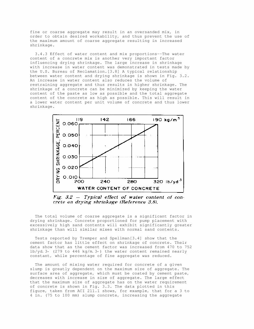
3.4.3 Effect of water content and mix proportions--The watercontent of a concrete mix is another very important factorinfluencing drying shrinkage. The large increase in shrinkagewith increase in water content was demonstrated in tests made bythe U.S. Bureau of Reclamation.[3.8] A typical relationshipbetween water content and drying shrinkage is shown in Fig. 3.2.An increase in water content also reduces the volume ofrestraining aggregate and thus results in higher shrinkage. Theshrinkage of a concrete can be minimized by keeping the watercontent of the paste as low as possible and the total aggregatecontent of the concrete as high as possible. This will result ina lower water content per unit volume of concrete and thus lowershrinkage.
The total volume of coarse aggregate is a significant factor indrying shrinkage. Concrete proportioned for pump placement withexcessively high sand contents will exhibit significantly greatershrinkage than will similar mixes with normal sand contents.
Tests reported by Tremper and Spellman[3.4] show that thecement factor has little effect on shrinkage of concrete. Theirdata show that as the cement factor was increased from 470 to 752lb/yd.3- (279 to 446 kg/m.3-) the water content remained nearlyconstant, while percentage of fine aggregate was reduced.
The amount of mixing water required for concrete of a givenslump is greatly dependent on the maximum size of aggregate. Thesurface area of aggregate, which must be coated by cement paste,decreases with increase in size of aggregate. The large effectthat the maximum size of aggregate has on the water requirementof concrete is shown in Fig. 3.3. The data plotted in thisfigure, taken from ACI 211.1 shows, for example, that for a 3 to4 in. (75 to 100 mm) slump concrete, increasing the aggregate
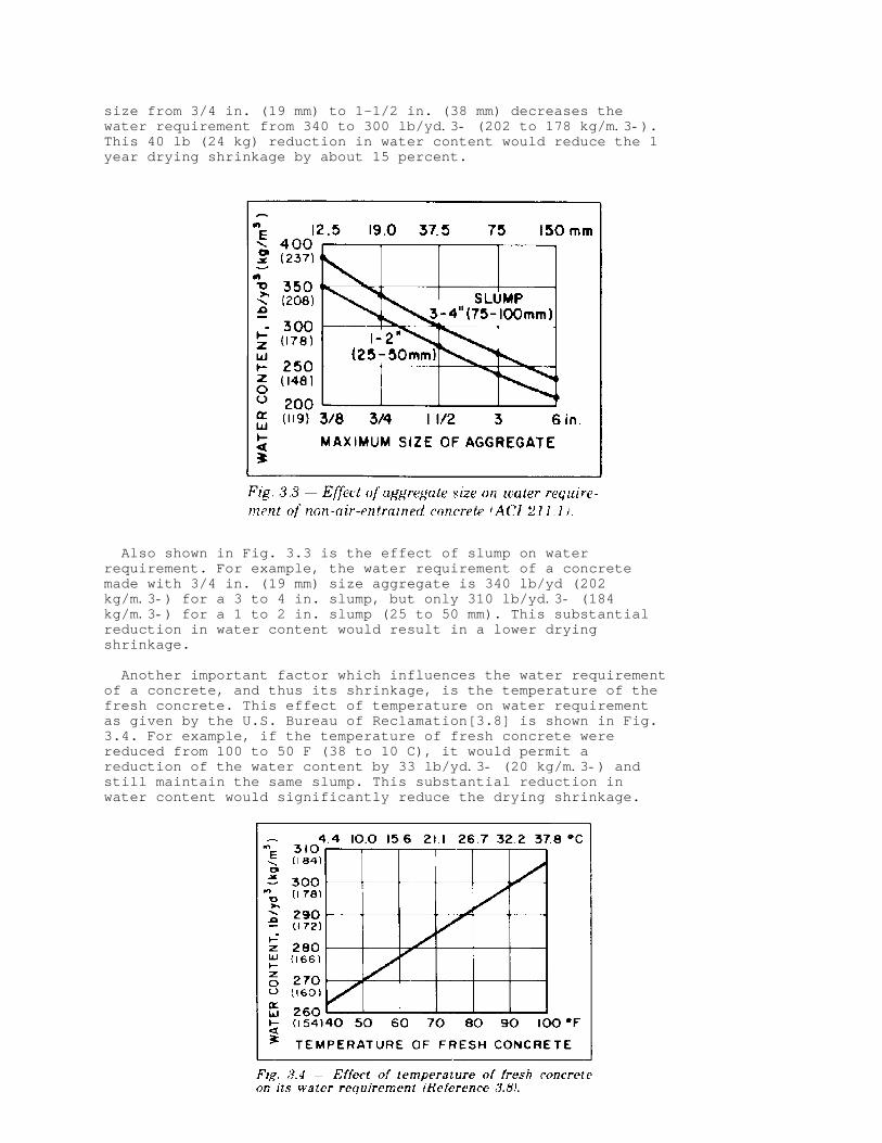
size from 3/4 in. (19 mm) to 1-1/2 in. (38 mm) decreases thewater requirement from 340 to 300 lb/yd.3- (202 to 178 kg/m.3-).This 40 lb (24 kg) reduction in water content would reduce the 1year drying shrinkage by about 15 percent.
Also shown in Fig. 3.3 is the effect of slump on waterrequirement. For example, the water requirement of a concretemade with 3/4 in. (19 mm) size aggregate is 340 lb/yd (202kg/m.3-) for a 3 to 4 in. slump, but only 310 lb/yd.3- (184kg/m.3-) for a 1 to 2 in. slump (25 to 50 mm). This substantialreduction in water content would result in a lower dryingshrinkage.
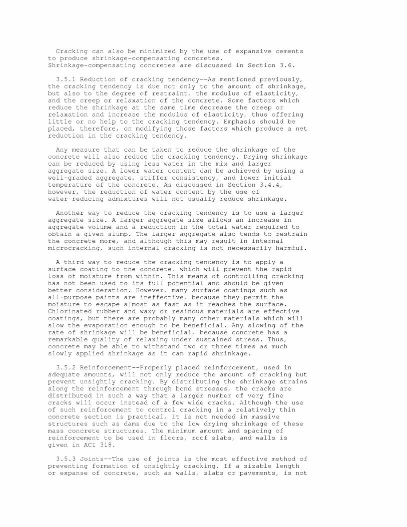
Another important factor which influences the water requirementof a concrete, and thus its shrinkage, is the temperature of thefresh concrete. This effect of temperature on water requirementas given by the U.S. Bureau of Reclamation[3.8] is shown in Fig.3.4. For example, if the temperature of fresh concrete werereduced from 100 to 50 F (38 to 10 C), it would permit areduction of the water content by 33 lb/yd.3- (20 kg/m.3-) andstill maintain the same slump. This substantial reduction inwater content would significantly reduce the drying shrinkage.

From the above discussion it must be concluded that, tominimize the drying shrinkage of concrete, the water content of amix should be kept to a minimum. Any practice that increases thewater requirement, such as the use of high slumps, hightemperatures of the fresh concrete or the use of smaller sizecoarse aggregate, will substantially increase shrinkage and thuscracking of the concrete.
3.4.4 Effect of chemical admixtures--Chemical admixtures areused to impart certain desirable properties to the concrete.Those most commonly used include air-entraining admixtures,water-reducing admixtures, set-retarding admixtures, andaccelerators.
It would be expected that when using an air-entrainingadmixture, the increase in the amount of air voids would increasedrying shrinkage. However, because entrainment of air permits areduction in water content with no reduction in slump, theshrinkage is not appreciably affected by air contents up to about5 percent.[3.8] Some air-entraining agents are strong retardersand contain accelerators which may increase drying shrinkage by 5to 10 percent.
Although the use of water-reducing and set-retarding admixtureswill permit a reduction in the water content of a concrete mix,it will usually not result in a decrease in drying shrinkage.Actually some of these admixtures may even increase the shrinkageat early ages of drying, although the later age shrinkage ofthese concretes will be about the same as that of correspondingmixes with no admixtures.
The use of calcium chloride, a common accelerator, will resultin a substantial increase in drying shrinkage, especially at theearly ages of drying. Tests made by the California Department ofTransportation[3.4] showed that the 7 day shrinkage of a concretecontaining 1.0 percent of calcium chloride was about double thatobtained for the control mix without admixture. However, after 28days of drying, the shrinkage of the concrete containing calciumchloride was only about 40 percent greater than that of thecontrol mix.
3.4.5 Effect of pozzolans--Fly ash and a number of naturalmaterials such as opaline cherts and shales, diatomaceous earth,tuffs and pumicites are pozzolans used in portland cementconcrete. The use of some natural pozzolans can increase thewater demand as well as the drying shrinkage of the concrete.Also, it was observed that the use of some of these pozzolansincreased drying shrinkage although they had little effect on thewater content of the concrete. Some fly ashes have little effecton drying shrinkage, while others may increase the shrinkage ofthe concrete. All of these observations are based on results oftests made on laboratory size specimens. However, as noted inSection 3.4.7 and Fig. 3.6, the larger the concrete member, thelower the shrinkage. This may explain the negligible differencein shrinkage cracking of field structures, with and withoutpozzolan, despite clearly greater shrinkage of the concretes withpozzolans in laboratory tests on small size specimens.
3.4.6 Effect of duration of moist curing--Carlson[3.6] reportedthat the duration of moist curing of concrete does not have mucheffect on drying shrinkage. This is substantiated by the test

results of the California Department of Transportation[3.4] whichshow substantially the same shrinkage in concrete that was moistcured for 7, 14, and 28 days before drying was started. As far asthe cracking tendency of the concrete is concerned, prolongedmoist curing may not necessarily be beneficial. Although thestrength increases with age, the modulus of elasticity alsoincreases by almost as large a percentage, and the net result isonly a slight increase in the tensile strain which the concretecan withstand.
Steam curing at atmospheric pressure, which is commonly used inthe manufacture of precast structural elements, will reducedrying shrinkage (ACI 517). Also, because stream curing willproduce a high early-age strength of the concrete, it will reduceits tendency to crack, since the precast members areunrestrained.
3.4.7 Influence of size of member--The size of a concretemember will influence the rate at which moisture moves from theconcrete and thus influence the rate of shrinkage. Carlson[3.9]has shown that for a concrete exposed to a relative humidity of50 percent, drying will penetrate only about 3 in. (75 mm) in 1month and about 2 ft (0.6 m) in 10 years. Fig. 3.5 shows histheoretical curves for the drying of slabs. Hansen andMattock[3.10] made an extensive investigation of the influence ofsize and shape of member on the shrinkage and creep of concrete.They found that both the rate and the final values of shrinkageand creep decrease as the member becomes larger.
This significant effect of size of member on drying shrinkageof concrete must be considered when evaluating the potentialshrinkage of concrete in structures based on the shrinkage ofconcrete specimens in the laboratory. The rate and magnitude ofshrinkage of a small laboratory specimen will be much greaterthan that of the concrete in the structures. Test results ofseveral studies carried out to compare the shrinkage of concrete

in walls and slabs in the field with the shrinkage of smalllaboratory specimens have shown, as expected, that the shrinkageof the concrete in a field structures only a fraction of thatobtained on the laboratory specimens. Even in laboratory teststhe size of the specimen used has a significant influence onshrinkage. As an example of the effect of specimen size onshrinkage is the data presented in Fig. 3.6, giving the resultsof shrinkage tests obtained on four different size concreteprisms. It will be noted that the shrinkage of the prisms havinga cross section of 3 x 3 in. (7.5 x 7.5 cm) was more than 50percent greater than that of the concrete prism having a crosssection of 5 x 6 in. (12.5 x 15 cm).
3.5--Control of shrinkage cracking
Concrete tends to shrink due to drying whenever its surfacesare exposed to air of low relative humidity. Since various kindsof restraint prevent the concrete from contracting freely, thepossibility of cracking must be expected unless the ambientrelative humidity is kept at 100 percent or the concrete surfacesare sealed to prevent loss of moisture. The control of crackingconsists of reducing the cracking tendency to a minimum, usingadequate and properly positioned reinforcement, and using controljoints. The CEB-FIP Code give quantitative recommendations on thecontrol of cracking due to shrinkage, listing variouscoefficients to determine the shrinkage levels that can beexpected. Control of cracking by correct construction practicesis covered in Chapter 8 of this report, which includesspecifications to minimize drying shrinkage (Section 8.6).
Cracking can also be minimized by the use of expansive cementsto produce shrinkage-compensating concretes.Shrinkage-compensating concretes are discussed in Section 3.6.
3.5.1 Reduction of cracking tendency--As mentioned previously,the cracking tendency is due not only to the amount of shrinkage,but also to the degree of restraint, the modulus of elasticity,and the creep or relaxation of the concrete. Some factors whichreduce the shrinkage at the same time decrease the creep orrelaxation and increase the modulus of elasticity, thus offeringlittle or no help to the cracking tendency. Emphasis should beplaced, therefore, on modifying those factors which produce a netreduction in the cracking tendency. Any measure that can be taken to reduce the shrinkage of theconcrete will also reduce the cracking tendency. Drying shrinkagecan be reduced by using less water in the mix and largeraggregate size. A lower water content can be achieved by using awell-graded aggregate, stiffer consistency, and lower initialtemperature of the concrete. As discussed in Section 3.4.4,however, the reduction of water content by the use ofwater-reducing admixtures will not usually reduce shrinkage.
Another way to reduce the cracking tendency is to use a largeraggregate size. A larger aggregate size allows an increase inaggregate volume and a reduction in the total water required toobtain a given slump. The larger aggregate also tends to restrainthe concrete more, and although this may result in internalmicrocracking, such internal cracking is not necessarily harmful.
A third way to reduce the cracking tendency is to apply asurface coating to the concrete, which will prevent the rapidloss of moisture from within. This means of controlling crackinghas not been used to its full potential and should be givenbetter consideration. However, many surface coatings such asall-purpose paints are ineffective, because they permit themoisture to escape almost as fast as it reaches the surface.Chlorinated rubber and waxy or resinous materials are effectivecoatings, but there are probably many other materials which willslow the evaporation enough to be beneficial. Any slowing of therate of shrinkage will be beneficial, because concrete has aremarkable quality of relaxing under sustained stress. Thus,concrete may be able to withstand two or three times as muchslowly applied shrinkage as it can rapid shrinkage.
3.5.2 Reinforcement--Properly placed reinforcement, used inadequate amounts, will not only reduce the amount of cracking butprevent unsightly cracking. By distributing the shrinkage strainsalong the reinforcement through bond stresses, the cracks aredistributed in such a way that a larger number of very finecracks will occur instead of a few wide cracks. Although the useof such reinforcement to control cracking in a relatively thinconcrete section is practical, it is not needed in massivestructures such as dams due to the low drying shrinkage of thesemass concrete structures. The minimum amount and spacing ofreinforcement to be used in floors, roof slabs, and walls isgiven in ACI 318.
3.5.3 Joints--The use of joints is the most effective method ofpreventing formation of unsightly cracking. If a sizable lengthor expanse of concrete, such as walls, slabs or pavements, is not

provided with adequate joints to accommodate shrinkage, it willmake its own "joints" by cracking.
Contraction joints in walls are made, for example, by fasteningto the forms wood or rubber strips which leave narrow verticalgrooves in the concrete on the inside and outside of the wall.Cracking of the wall due to shrinkage should occur at thegrooves, relieving the stress in the wall and thus preventingformation of unsightly cracks. These grooves should be sealed onthe outside of the wall to prevent penetration of moisture. Sawedjoints are commonly used in pavements, slabs and floors.
Joint location depends on the particulars of placement. Eachjob must be studied individually to determine where joints shouldbe placed.*
(* Guidance on joint sealants and control joint location inslabs is available in ACI 504 and in ACI 302, respectively.)
3.6--Shrinkage compensating concretes
Shrinkage-compensating concretes made with expansive cementscan be used to minimize or eliminate shrinkage cracking. Theproperties and use of expansive cement concretes is published innumerous papers and reports.[3.11,3.12] Of the several types ofexpansive cements produced, the Type K shrinkage-compensatingexpansive cement is most commonly used in the United States.
In a reinforced concrete, the expansion of the cement pasteduring the first few days of curing will develop a low level ofprestress inducing compressive stresses in the concrete andtensile stresses in the steel. The level of compressive stressesdeveloped in the shrinkage-compensating concretes ranges from 25to 100 psi (0.2 to 0.7 MPa). When subjected to drying shrinkage,the contraction of the concrete will result in a reduction orelimination of its precompression. The initial precompression ofthe concrete minimizes the magnitude of any tensile stress thatmay ultimately develop due to shrinkage, and thus reduce oreliminate the tendency to cracking. This basic concept of the useof expansive cement to produce a shrinkage-compensating concreteis illustrated in Fig. 3.7.
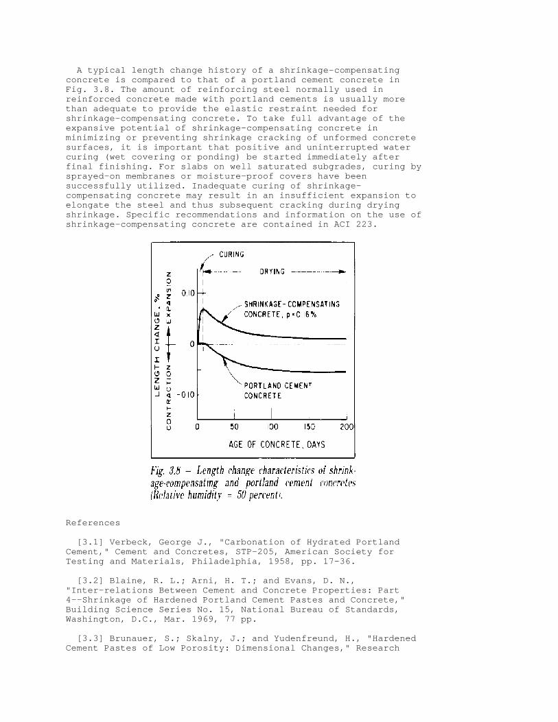
A typical length change history of a shrinkage-compensatingconcrete is compared to that of a portland cement concrete inFig. 3.8. The amount of reinforcing steel normally used inreinforced concrete made with portland cements is usually morethan adequate to provide the elastic restraint needed forshrinkage-compensating concrete. To take full advantage of theexpansive potential of shrinkage-compensating concrete inminimizing or preventing shrinkage cracking of unformed concretesurfaces, it is important that positive and uninterrupted watercuring (wet covering or ponding) be started immediately afterfinal finishing. For slabs on well saturated subgrades, curing bysprayed-on membranes or moisture-proof covers have beensuccessfully utilized. Inadequate curing of shrinkage-compensating concrete may result in an insufficient expansion toelongate the steel and thus subsequent cracking during dryingshrinkage. Specific recommendations and information on the use ofshrinkage-compensating concrete are contained in ACI 223.
References
[3.1] Verbeck, George J., "Carbonation of Hydrated PortlandCement," Cement and Concretes, STP-205, American Society forTesting and Materials, Philadelphia, 1958, pp. 17-36.
[3.2] Blaine, R. L.; Arni, H. T.; and Evans, D. N.,"Inter-relations Between Cement and Concrete Properties: Part4--Shrinkage of Hardened Portland Cement Pastes and Concrete,"Building Science Series No. 15, National Bureau of Standards,Washington, D.C., Mar. 1969, 77 pp.
[3.3] Brunauer, S.; Skalny, J.; and Yudenfreund, H., "HardenedCement Pastes of Low Porosity: Dimensional Changes," Research

Report No. 69-8, Engineering Research and Development Bureau, NewYork State Department of Transportation, Albany, Nov. 1969, 12pp.
[3.4] Tremper, Bailey, and Spellman, Donald L., "Shrinkage ofConcrete--Comparison of Laboratory and Field Performance,"Highway Research Record. Highway Research Board, No. 3, 1963, pp.30-61.
[3.5] Lerch, William, "The Influence of Gypsum on the Hydrationand Properties of Portland Cement Pastes," Proceedings, ASTM, V.46, 1946, pp. 1252-1297.
[3.6] Carlson, Roy W., "Drying Shrinkage of Concrete asAffected by Many Factors," Proceedings, ASTM, V. 38, Part II,1938, pp. 419-437.
[3.7] Reichard, T. W., "Creep and Drying Shrinkage ofLightweight and Normal Weight Concrete," Monograph 74, NationalBureau of Standards, Washington, D.C., 1964, 30 pp.
[3.8] Concrete Manual, 8th Edition, U.S. Bureau of Reclamation,Denver, 1975, 627 pp. [3.9] Carlson, Roy W., "Drying Shrinkage of Large ConcreteMembers," ACI JOURNAL, Proceedings V. 33, No. 3, Jan.-Feb. 1937,pp. 327-336.
[3.10] Hansen, Torben C., and Mattock, Alan H., "Influence ofSize and Shape of Member on the Shrinkage and Creep of Concrete,"ACI JOURNAL, Proceedings V. 63, No. 2, Feb. 1966, pp. 267-290.
[3.11] ACI Committee 223, "Expansive Cement Concretes--PresentState of Knowledge," ACI JOURNAL, Proceedings V. 67, No. 8, Aug.1970, pp. 583-610.
[3.12] Klein Symposium on Expansive Cement Concretes, SP-38,American Concrete Institute, Detroit, 1973, 491 pp.
CHAPTER 4--CONTROL OF CRACKING IN FLEXURAL MEMBERS*
(* Principal authors: Edward C. Nawy and Peter Gergely.)
4.1--Introduction
With the regular use of high strength reinforcing steel and thestrength design approach for reinforced concrete, and higherallowable stresses in prestressed concrete design, the control ofcracking may be as important as the control of deflection inflexural members. Internal cracking in concrete can start atstress levels as low as 3000 psi (20.7 MPa) in the reinforcement.Crack control is important to promote the aesthetic appearance ofstructures, and for many structures, crack control plays animportant role in the control of corrosion by limiting thepossibilities for entry of moisture and salts which, togetherwith oxygen, can set the stage for corrosion.
This chapter is concerned primarily with cracks caused byflexural and tensile stresses, but temperature, shrinkage, shearand torsion may also lead to cracking.[4.1] Cracking in certain
specialized structures, such as reinforced concrete tanks, binsand silos, is not covered in this report. For information oncracking concrete in these structures, see Reference 4.2 and ACI313.
Extensive research studies on the cracking behavior of beamshave been conducted over the last 50 years. Most of them arereported in ACI Bibliography No. 9 on crack control.[4.3] Othersare referenced in this chapter. Reference 4.1 contains anextensive review of cracking in reinforced concrete structures.Several of the most important crack prediction equations arereviewed in the previous committee report.[1.1] Additional workpresented in the CEB-FIP Model Code for Concrete Structure givesthe European approach to crack width evaluation and permissiblecrack widths.
Recently, fiber glass rods have been used as a reinforcingmaterial.[4.4] To date, experience is limited, and crack controlin structures reinforced with fiber glass rods is not addressedin this report. It is expected, however, that future committeedocuments will address crack control in structures using this andother new systems as they come into use.
4.2--Crack control equations for reinforced concrete beams
A number of equations have been proposed for the prediction ofcrack widths in flexural members; most of them are reviewed inthe previous committee report[1.1] and in key publications listedin the references. Most equations predict the probable maximumcrack width, which usually means that about 90 percent of thecrack widths in the member are below the calculated value.However, research has shown that isolated cracks in beams inexcess of twice the width of the computed maximum can sometimesoccur,[4.4] though generally the coefficient of variation ofcrack width is about 40 percent.[4.1] Evidence also existsindicating that this range in crack width randomness may increasewith the size of the member.[1.1] Besides limiting the computedmaximum crack width to a given value, the designer shouldestimate the percentage of cracks above this value which can betolerated.
Crack control equations recommended by ACI Committee 224 andthe Comite Euro-International du Beton (CEB) are presented below.
4.2.1 ACI Committee 224 recommendations--Requirements for crackcontrol in beams and thick one-way slabs in the ACI Building Code(ACI 318) are based on the statistical analysis[4.6] of maximumcrack width data from a number of sources. Based on the analysis,the following general conclusions were reached:
1. The steel stress is the most important variable.
2. The thickness of the concrete cover is an importantvariable, but not the only geometric consideration.
3. The area of concrete surrounding each reinforcing bar isalso an important geometric variable.
4. The bar diameter is not a major variable.

5. The size of the bottom crack width is influenced by theamount of strain gradient from the level of the steel to thetension face of the beam. The equations that were considered to best predict the mostprobable maximum bottom and side crack widths are:
w+b, = 0.091 .3-%t+b,A ß (f+s, - 5) x 10. -3- (4.1a)
0.091 3%t+s,A w+s, = ))))))))))))))) (f+s, - 5) x 10 . -3- (4.1b) 1 + t+s,/h+1,
where
w+b, = most probable maximum crack width at bottom of beam, in.
w+s, = most probable maximum crack width at level of reinforcement, in.
f+s, = reinforcing steel stress, ksi
A = area of concrete symmetric with reinforcing steel divided by number of bars, in.²
t+b, = bottom cover to center of bar, in.
t+s, = side cover to center of bar, in.
ß = ratio of distance between neutral axis and tension face to distance between neutral axis and centroid of reinforcing steel . 1.20 in beams
h+1, = distance from neutral axis to the reinforcing steel, in.
Simplification of Eq. (4.1a) yielded the following equation
w = 0.076ßf+s, .3-%d+c,A x 10. -3- (4.2)where
w = most probable maximum crack width, in.
d+c, = thickness of cover from tension fiber to center of bar closest thereto, in.
When the strain, ,+s,, in the steel reinforcement is usedinstead of stress, f+s,, Eq. (4.2) becomes w = 2.2 ß ,+s, .3-%d+c,A (4.3)where
,+s, = strain in the reinforcement

Eq. (4.3) is valid in any system of measurement.
The cracking behavior in thick one-way slabs is similar to thatin shallow beams. For one-way slabs having a clear concrete coverin excess of 1 in. (25.4 mm), Eq. (4.2) can be adequately appliedif ß = 1.25 to 1.35 is used.
ACI 318 Section 10.6 uses Eq. (4.2) with ß = 1.2 in thefollowing form
z = f+s, .3-%d+c,A (4.2a) Using the specified cover in ACI 318, maximum allowable z = 175kips per in. for interior exposure corresponds to a limitingcrack width of 0.016 in. (0.41 mm).
The Code allows a value of z = 145 kips per in. for exteriorexposure based on a crack width value of 0.013 in., (0.33 mm),which may be excessive based on Table 4.1. While application ofEq. (4.2a) [Eq. (10.4) of ACI 318-77] to beams gives adequatecrack control values, its application to one-way slabs withstandard 3/4 in. (19 mm) cover and reinforced with steel of 60ksi (414 MPa) or lower yield strength results in largereinforcement spacings. However, the provisions of Code Section7.6.5 indirectly limit the spacing of such reinforcement inone-way slabs.
TABLE 4.1--Tolerable crack widths, reinforced concrete644444444444444444444444444444444444444444444444444444444444475 Tolerable 55 Exposure condition crack width, in. (mm) 5K))))))))))))))))))))))))))))))))))))))))))))))))))))))))))))M5 Dry air or protective membrane 0.016 (0.41) 55 Humidity, moist air, soil 0.012 (0.30) 55 Deicing chemicals 0.007 (0.18) 55 Seawater and seawater spray; 55 wetting and drying 0.006 (0.15) 55 Water retaining structures* 0.004 (0.10) 594444444444444444444444444444444444444444444444444444444444448* Excluding nonpressure pipes
ACI 340.1R contains design aids for the application of Eq.(4.2a).
4.2.2 CEB recommendations--Crack control recommendationsproposed in the European Model Code for Concrete Structures applyto prestressed as well as reinforced concrete and can besummarized as follows:
The mean crack width, w+m,, in beams is expressed in terms ofthe mean crack spacing, s+rm,, such that where
w+m, = ,+sm, s+rm, (4.4)
where +) )), * +) ),²* f+s, * * f+sr, * * f+s,,+sm, = ))))))* 1 - < *))))))) * * # 0.4 )))))) (4.5) E+s, * * f+s, * * E+s, * .) )- *

.) ))- and represents the average strain in the steel.
f+s, = steel stress at the crack
f+sr, = steel stress at the crack due to forces causing cracking at the tensile strength of concrete
< = bond coefficient, 1.0 for ribbed bars, reflecting influence of load repetitions and load duration
The mean crack spacing is
+) ), * s * d+b, s+rm, = 2 * c + )))) * + <+2,<+3, )))))) (4.6) * 10 * â+R, .) )-
where
c = clear concrete cover
s = bar spacing, limited to 15d+b,
<+2, = 0.4 for ribbed bars
<+3, = depends on the shape of the stress diagram, 0.125 forbending
â+R, = A+s,/A+t, A+t, = effective area in tension, depending on arrangement ofbars and type of external forces; it is limited by a line c +7d+b, from the tension face for beams; in the case of slabs, notmore than halfway to the neutral axis
A simplified formula can be derived for the mean crack width inbeams with ribbed bars. +) ), f+s, * d+b,* w+m, = 0.7 ))))) * 3c + 0.05 )))))* (4.7) E+s, * â+R,* .) )-
A characteristic value of the crack width, presumablyequivalent to the probable maximum value, is given as 1.7 w+m,.
4.3--Crack control in two-way slabs and plates
Crack control equations for beams underestimate the crackwidths developed in two-way slabs and plates[4.7] and do not tellthe designer how to space the reinforcement. The crackingmechanism in two-way slabs and plates is controlled primarily bythe steel stress level and the spacing of the reinforcement inthe two perpendicular directions. In addition, the clear concretecover in two-way slabs and plates is nearly constant [3/4 in. (19

mm) for interior exposure], whereas it is a major variable in thecrack control equations for beams.
Analysis of data in the only major work on cracking in two-wayslabs and plates[4.7] has provided the following equation forpredicting the maximum crack width:
where the radical '+1, = d+b1, s+2,/â+t1, is termed the gridindex, and can be transformed into
+) ), * s+1,s+2,d+c, 8 * '+1, = *)))))))))))))) )))))* * d+b1, B * .) )-
k = fracture coefficient, having a value k = 2.8 x 10. -5- for uniformly loaded restrained two-way action square slabs and plates. For concentrated loads or reactions, or when the ratio of short to long span is less than 0.75 but larger than 0.5, a value of k = 2.1 x 10. -5- is applicable. For span aspect ratios 0.5, k = 1.6 x 10. -5-
ß = (as defined in Section 4.2.1) 1.25 (chosen to simplify c calculations though varies between 1.20 and 1.35)
f+s, = actual average service load stress level, or 40 percent of the design yield strength f+y,, ksi
d+b1, = diameter of the reinforcement in direction "1" closest to the concrete outer fibers, in.
s+1, = spacing of the reinforcement in direction "1", in.
s+2, = spacing of the reinforcement in perpendicular direction "2", in.
"1" = direction of reinforcement closest to the outer concrete fibers; this is the direction for which crack control check is to be made
â+t1, = active steel ratio
Area of steel A+s, per ft width = ))))))))))))))))))))))))))))))))) 12 (d+b1, + 2C+1,)
where C+1, is clear concrete cover measured from the tensile face of concrete to the nearest edge of the reinforcing bar in direction "1"

w = crack width at face of concrete, in., caused by flexural load
Subscripts 1 and 2 pertain to the directions of reinforcement.
For simply supported slabs, the value of k should be multipliedby 1.5. Interpolated k values apply for partial restraint at theboundaries. For zones of flat plates where transverse steel isnot used or when its spacing s+2, exceeds 12 in., use s+2, = 12in. in the equation.
If strain is used instead of stress, Eq. [4.8] becomes
where values of the k+1, = 29 x 10.3- times the k valuespreviously listed. References 4.8 and 340.1R contain design aids for theapplication of these recommendations.
4.4--Tolerable crack width versus exposure conditions inreinforced concrete
Table 4.1 is a general guide for tolerable crack widths at thetensile face of reinforced concrete structures for typicalconditions and is presented as an aid to be used during thedesign process.
The table is based primarily on Reference 4.9. It is important tonote that these values of crack width are not always a reliableindication of the corrosion and deterioration to be expected. Inparticular, a larger cover, even if it leads to a larger surfacecrack width, may sometimes be preferable for corrosion control incertain environments. Thus, the designer must exerciseengineering judgment on the extent of crack control to be used.When used in conjunction with the recommendations presented inSections 4.2.1 and 4.2.3 to limit crack width, it should beexpected that a portion of the cracks in the structure willexceed these values by a significant amount.
4.5--Flexural cracking in prestressed concrete
Partially prestressed members, in which cracks may appear underworking loads, are used extensively. Cracks form in these memberswhen the tensile stress exceeds the modulus of rupture of the(6%f'+c, to 9%f'+c, concrete under short-term conditions). Thecontrol of these cracks is necessary mainly for esthetic reasons.The residual crack width, after removal of the major portion ofthe live load, is small [about 0.001 in. to 0.003 in. (0.03 to

0.08 mm)] and therefore, crack control is usually not necessaryif the live load is transitory.
The prediction of crack widths in prestressed concrete membershas received far less attention than in reinforced concretemembers. The available experimental data are limited and, at thesame time, the number of variables is greater in prestressedmembers.
4.5.1 Crack prediction equations--One approach to crackprediction, which relates it to the nonprestressed case, has twosteps. First the decompression moment is calculated, at which thestress at the tension face is zero. Then the member is treated asa reinforced concrete member and the increase in stress in thesteel is calculated for the additional loading. The expressionsgiven for crack prediction in nonprestressed beams may be used toestimate the cracks for the load increase above the decompressionmoment. A multiplication factor of about 1.5 is needed whenstrands, rather than deformed bars, are used nearest to the beamsurface in the prestressed member to account for the differencesin bond properties.
The difficulty with this approach is the complexity ofcalculations. The determination of the decompression moment and,especially, the stress in the steel is complicated and unreliableunless elaborate methods are used.[4.10] For this reason,approximate methods for crack width prediction are attractive.These are not much less accurate than the more complicatedmethods, and the lack of sufficient data, covering largevariations in the variables, precludes further refinements atthis date.
The CEB Model Code has the same equation for the prediction ofthe crack width in prestressed members as in nonprestressedmembers (see Section 4.2.2). The increase in steel strain iscalculated from the decompression stage. Several other equationshave been proposed.[4.11-4.20]
Limited evidence seems to indicate that unbonded membersdevelop larger cracks than bonded members. Nonprestresseddeformed bars may be used to reduce the width of the cracks toacceptable levels. The cracks in bonded post-tensioned membersare not much different from cracks in pretensioned beams.
4.5.2 Allowable crack widths--Some authors state that corrosionis a greater problem in prestressed concrete members because ofthe smaller area of steel used. However, recent researchresults[4.21] indicate that there is no general relationshipbetween cracking and corrosion in most circumstances.Furthermore, cracks close upon removal of the load, and the useof crack width limits should depend on the fluctuation andmagnitude of the live load.
4.6--Anchorage zone cracking in prestressed concrete
Longitudinal cracks frequently occur in the anchorage zones ofprestressed concrete members due to transverse tensile stressesset up by the concentrated forces.[4.22,4.23] Such cracks maylead to (or in certain cases are equivalent to) the failure ofthe member. Transverse reinforcement (stirrups) must be designedto restrict these cracks.

Two types of cracks may develop: spalling cracks which begin atthe end face (loaded surface) and propagate parallel to theprestressing force, and bursting cracks which develop along theline of the force or forces, but away from the end face.
For many years stirrups were designed to take the entirecalculated tensile force based on the analysis of the uncrackedsection. Classical and finite-element analyses show similarstress distributions for which the stirrups are to be provided.However, since experimental evidence shows that higher stressescan result[4.23] than indicated by these analyses, and theconsequences of under-reinforcement can be serious, it isadvisable to provide more steel than required by this type ofanalysis.
More recently, designs have been based on cracked sectionanalyses. A design procedure for post-tensioned members using acracked section analysis[4.24] has found acceptance with manydesigners. For pretensioned members, an empirical equation hasproven to be quite useful.[4.25]
Spalling cracks form between anchorages and propagate parallelto the prestressing forces and may cause gradual failure,especially when the force acts near and parallel to a free edge.Since analyses show that the spalling stresses in an uncrackedmember are confined to near the end face, it is important toplace the first stirrup near the end surface, and to distributethe stirrups over a distance equal to at least the depth of themember to fully account for both spalling and bursting stresses.Precast blocks with helical reinforcement may be used when theprestressing forces are large.
4.7--Tension cracking
The cracking behavior of reinforced concrete members in tensionis similar to that of flexural members, except that the maximumcrack width is larger than that predicted by the expressions forflexural members.[4.26,4.27] The lack of strain gradient, andresultant restraint imposed by the compression zone of flexuralmembers, is probably the reason for the larger tensile crackwidth.
Data are limited but it appears that the maximum tensile crackwidth may be expressed approximately in a form similar to thatused for flexural crack width.
w = 0.10f+s, .3-%d+c,A x 10. -3- (4.10)
References
[4.1] Leonhardt, Fritz, "Crack Control in Concrete Structures,"IABSE Surveys No. S4/77, International Association for Bridge andStructural Engineering, Zurich, 1977, 26 pp. [4.2] Yerlici, V. A., "Minimum Wall Thickness of CircularConcrete Tanks," Publication No. 35-II, International Associationfor Bridge & Structural Engineering, Zurich, 1975, p. 237.
[4.3] ACI Committee 224, "Causes, Mechanism, and Control of

Cracking in Concrete," ACI Bibliography No. 9, American ConcreteInstitute, Detroit, 1971, 92 pp.
[4.4] Nawy, Edward C,., and Neuwerth, G. E., "Behavior ofConcrete Slabs, Plates and Beams with Fiber Glass as MainReinforcement," Proceedings, ASCE, V. 103, ST2, Feb. 1977, pp.421-440.
[4.5] Clark, Arthur P., "Cracking in Reinforced ConcreteFlexural Members, ACI JOURNAL, Proceedings V. 52, No. 8, Apr.1956, pp. 851-862.
[4.6] Gergely, Peter, and Lutz, Leroy A., "Maximum Crack Widthin Reinforced Concrete Flexural Members," Causes, Mechanism, andControl of Cracking in Concrete, SP-20, American ConcreteInstitute, Detroit, 1968, pp. 87-117.
[4.7] Nawy, Edward G., and Blair, Kenneth W., "Further Studieson Flexural Crack Control in Structural Slab Systems," Cracking,Deflection, and Ultimate Load of Concrete Slab Systems, SP-30,American Concrete Institute, Detroit, 1971, pp. 1-41.
[4.8] Nawy, Edward G., "Crack Control Through ReinforcementDistribution in Two-Way Acting Slabs and Plates," ACI JOURNAL,Proceedings V. 69, No. 4, Apr. 1972, pp. 217-219.
[4.9] Nawy, Edward G., "Crack Control in Reinforced ConcreteStructures, ACI JOURNAL, Proceedings V. 65, No. 10, Oct. 1968,pp. 825-836.
[4.10] Nilson, Arthur H., Design of Prestressed Concrete, JohnWiley and Sons, New York, 1978, 526 pp.
[4.11] Abeles, Paul W., "Cracks in Prestressed Concrete Beams,"Proceedings, Fifth IABSE Congress (Lisbon, 1956), InternationalAssociation for Bridge and Structural Engineering, Zurich, 1956,pp. 707-720.
[4.12] Bennett, E. W., and Dave, N. J., "Test Performances andDesign of Concrete Beams with Limited Prestress," The StructuralEngineer (London), V. 47, No. 12, Dec. 1969, pp. 487-496.
[4.13] Holmberg, Ake, and Lindgren, Sten, "Crack Spacing andCrack Widths Due to Normal Force and Bending Moment," DocumentD2:1970, National Swedish Council for Building Research,Stockholm, 1970, 57 pp. [4.14] Rao, A.S.P.; Grandotra, K.; and Ramaswamy, G. S.,"Flexural Tests on Beams Prestressed to Different Degrees ofPrestress," Journal, Institution of Engineers (Calcutta), V. 56,May 1976.
[4.15] Bate, Stephen C. C., "Relative Merits of Plain andDeformed Wires in Prestressed Concrete Beams Under Static andRepeated Loading," Proceedings, Institution of Civil Engineers(London), V. 10, Aug. 1958, pp. 473-502.
[4.16] Bennett, E. W., and Chandrasekhar, C. S., "Calculationof the Width of Cracks in Class 3 Prestressed Beams,"Proceedings, Institution of Civil Engineers (London), V. 49, July1971, pp. 333-346.

[4.17] Hutton, S. G., and Loov, R. E., "Flexural Behavior ofPrestressed, Partially Prestressed, and Reinforced ConcreteBeams," ACI JOURNAL, Proceedings, V. 63, No. 12, Dec. 1966, pp.1401-1410.
[4.18] Krishna, Raju N.; Basavarajuiah, B. S.; and AhamedKurty, U. C., "Flexural Behavior of Pretensioned Concrete Beamswith Limited Prestress," Building Science, V. 8, No. 2, June1973, pp. 179-185.
[4.19] Stevens, R. F., "Tests on Prestressed ReinforcedConcrete Beams," Concrete (London), V. 3, No. 11, Nov. 1969, pp.457-462.
[4.20] Nawy, E. G., and Huang, P. T., "Crack and DeflectionControl of Pretensioned Prestressed Beams," Journal, PrestressedConcrete Institute, V. 22, No. 3, May-June 1977, pp. 30-47.
[4.21] Beeby, A. W., "Corrosion of Reinforcing Steel inConcrete and Its Relation to Cracking," The Structural Engineer(London), V. 56A, No. 3, Mar. 1975, pp. 77-81.
[4.22] Gergely, Peter, "Anchorage Systems in PrestressedConcrete Pressure Vessels; Anchorage Zone Problems,"ORNL-TM-2378, Oak Ridge National Laboratory, U.S. Atomic EnergyCommission, Oak Ridge, Tenn., 1969, pp. 1-49.
[4.23] Zielinski, J. L., and Rowe, R. E., "An Investigation ofthe Stress Distribution in the Anchorage Zones of Post-TensionedConcrete Members," Technical Report No. 9, Cement and ConcreteAssociation, London, Sept. 1960, 32 pp.
[4.24] Gergely, P., and Sozen, M. A., "Design of Anchorage ZoneReinforcement in Prestressed Concrete Beams," Journal,Prestressed Concrete Institute, V. 12, No. 2, Mar.-Apr. 1967, pp.63-75. [4.25] Marshall, W. T., and Mattock, A. H., "Control ofHorizontal Cracking in the Ends of Pretensioned ConcreteGirders," Journal, Prestressed Concrete Institute, V. 7, No. 5,Aug.-Oct. 1962, pp. 56-74.
[4.26] Broms, Bengt B., "Crack Width and Crack Spacing inReinforced Concrete Members," ACI JOURNAL, Proceedings, V. 62,No. 10, Oct. 1965, pp. 1237-1256.
[4.27] Broms, Bengt B., and Lutz, Leroy A., "Effects ofArrangement of Reinforcement on Crack Width and Spacing ofReinforced Concrete Members," ACI JOURNAL, Proceedings V. 62, No.11, Nov. 1965, pp. 1395-1410.
CHAPTER 5--LONG-TERM EFFECTS ON CRACKING*
(*Principal authors: David Darwin and Ernest K. Schrader.)
5.1--Introduction
Cracking in concrete is affected by the long-term conditions towhich the concrete element is subjected. In most cases, long-termexposure and long-term loading extend the magnitude of cracks inboth reinforced and plain concrete. The discussion in thischapter summarizes the major long-term factors which affect thecrack control performance of concrete.
5.2--Effects of long-term loading
As discussed in Chapter 2, both sustained and cyclic loadingincrease the amount of microcracking in concrete. The totalamount of microcracking appears to be a function of the totalstrain and is largely independent of the method by which thestrain is induced. Microcracking due to long-term loading maywell be an effect, rather than a major cause, of creep, andmicrocracks formed at service load levels do not seem to have agreat affect on the strength or serviceability of concrete.
The effect of sustained or repetitive loading on macroscopiccracking, however, may be an important consideration in theserviceability of reinforced concrete members, especially interms of corrosion of reinforcing steel and appearance.
The increase in crack width due to long-term or repetitiveloading can vary between 10 percent and 1,000 percent over thespan of several years.[5.1-5.8] While there is a large scatter inthe data, information obtained from sustained loading tests of upto 2 years[5.7,5.8] and fatigue tests with up to one millioncycles[5.4,5.5,5.8,5.9] indicate that a doubling of crack widthwith time can be expected. Under most conditions, the spacing ofcracks does not change with time at constant levels ofstress.[5.4,5.7,5.8] An exception to this occurs at low loads orin beams with high percentages of reinforcement, in which casethe total number and width of cracks increase substantially afterthe loading has begun.[5.2,5.4,5.8] The largest percentageincrease in crack width is then expected in flexural memberssubject to low levels of load, since the cracks take more time todevelop.
For both prestressed and reinforced concrete flexural members,long-term loading and repetitive loading seem to give about thesame crack widths and spacing.[5.9] The rate of crackdevelopment, however, is considerably faster under repetitiveloading.[5.5,5.8-5.10]
As discussed in Chapter 4, crack width is a function of cover.For short-term static and fatigue loading, surface crack width isapproximately proportional to the steel strain.[5.7,5.8,5.10]Cracks grow in width under sustained loading at a decreasingrate. However, the rate of growth is faster than the averageobserved surface strain at the level of the steel. For long termloading, crack width is proportional to the steel strain(including the effects of creep), plus the strain induced in theconcrete due to shrinkage.[5.7]

Under initial loads, cracks adjacent to reinforcement arerestricted by the bond between the steel and the concrete,[5.7,5.11] and thus the width of surface cracks do not provide agood indication of the exposure of the reinforcing steel tocorrosive conditions. Over a period of time, however, theadhesion bond between the steel and the concrete undergoesbreakdown. After about 2 years, the crack width at thereinforcement is approximately equal to the crack width at thesurface.[5.7] At this stage, cracks in flexural members aretriangular in shape increasing in width from the neutral axis tothe soffit, and are approximately uniform across the width of thebeam. Therefore, after a few years, the width of a surface crackprovides a good estimate of the crack width at the level of thereinforcing steel.
Many questions remain as to the importance of crack width onthe serviceability of reinforced and prestressed concretemembers.[5.12,5.13,5.14] Added cover is generally acknowledged asa method of improving the corrosion protection for reinforcingsteel. Since additional cover also results in added surface crackwidth, and since this surface crack width appears to provide agood estimate of the crack width at the level of the steel, theentire question of the importance of crack width on corrosionprotection remains open. It does seem clear that crack widthspredicted on the basis of short term static tests do not providea precise guide to crack widths in structures actually inservice.
5.3--Environmental effects
The long-term effects of an adverse environment in bothproducing and in enlarging concrete cracks can[5.15,5.16] bedamaging to both concrete and reinforcement. If concrete is notresistant to freezing and thawing when critically saturated, itwill develop cracks when frozen. The lack of such resistance maybe due to either the use of non-frost-resistant coarse aggregateor the failure to produce a satisfactory air-void system orfailure to protect the concrete from freezing prior to thereduction of the freezable water content by maturity to atolerable range. The achievement of critical saturation innon-frost-resistant concrete may be facilitated by the presenceof preexisting cracks which allow entry of water more readilythan would be the case otherwise. The initiation of D-crackingnear joints or other cracks in pavements is a good example. Inmore extreme cases, it is not uncommon for cracks in the roadwaydeck of dams and navigation locks (caused either by thermalstress or shrinkage of the richer topping mix) to spall due towater which freezes in the cracks themselves (independent of thefrost resistance of the concrete). On the other hand, preexistingcracks may also function to allow concrete to dry below criticalsaturation before freezing, when this might not occur in theabsence of such cracks. Hence, the role of cracks as they effectthe deficiencies in frost resistance will vary with theenvironmental conditions (e.g., typical time of drying afterwetting before freezing), crack width, ability of cracks todrain, etc.
If the aggregate used in the concrete is durable underfreeze-thaw conditions and the strength of the concrete is high,the concrete durability will better. (ACI 201.2R). Field exposuretests of reinforced concrete beams[5.17] (subjected to freezing

and thawing and an ocean side environment) indicate that the useof air-entrained concrete made the beams more resistant toweathering than the use of non-air-entrained concrete. Beams withmodern deformed bars were found to be more durable than thoseusing old-style deformations. Maximum crack widths did notincrease with time when the steel stress was less than 30 ksi,(210 MPa) but did increase substantially (50 to 100 percent) overa 9 year period when the steel was 30 ksi (210 MPa) or more.
5.4--Aggregate and other effects
Concrete may crack as the result of expansive reactions betweenaggregate and alkalis derived from cement hydration, admixturesor external sources (e.g., curing water, ground water, alkalinesolutions stored or used in the finished structure).
Possible solutions to these problems include limitations onreactive constituents in the aggregate, limitations on the alkalicontent of cement, or addition of a satisfactory pozzolanicmaterial. The potential for some expansive reactions, e.g.,alkali-carbonate, is not reduced by pozzolanic admixtures. ACI201.2R and Reference 5.18 give details on identification andevaluation of aggregate reactivity.
Based on reports of ACI Committees 201 and 212[5.15,5.16] thepossible hazard of using calcium chloride in a water-soluble saltenvironment warrants a recommendation against its use under suchcircumstances. Also, the use of calcium chloride in reinforcedstructures exposed to unusually moist environments is to beavoided regardless of the presence or absence of water-solublesalts in adjacent waters and soils.
Detrimental conditions may also result from the application ofdeicing salts to the surface of hardened concrete. When suchapplications are necessary, calcium chloride or sodium chlorideshould be used and only within recommended application rates.Concrete subjected to water soluble salts should be air entrained[6.5 to 7.5 percent for normal 3/4 in. (19 mm) MSA concrete and4.5 to 5.5 percent for 1-1/2 in. (38 mm) MSA concrete], shouldhave adequate cover (about 2 in.), and should be made with ahigh-quality mix yielding low permeability.
5.5--Use of polymers in improving cracking characteristics
Extensive work is available on the use of polymers in modifyingthe characteristics of concrete.[5.19,5.20,5.21] Polymer-portlandcement concretes have a large deformation capacity, high tensileand compressive strengths and negligible permeability. Thetensile splitting strength can be as high as 1550 psi (10.7MPa).[5.22] Polymer impregnation is another method of introducingbeneficial polymer systems into concrete. This procedure createsa 'layer' of high quality material to the depth that has beenimpregnated. These materials are discussed in greater detail inChapter 6.
Because of these desirable characteristics, it is expected thatstructural elements made with polymer modified concrete willexhibit superior serviceability in cracking, deflection, creep,shrinkage, and permeability.

References
[5.1] Bate, Stephen C. C., "A Comparison Between PrestressedConcrete and Reinforced Concrete Beams Under Repeated Loading,"Proceedings, Institution of Civil Engineers (London), V. 24, Mar.1963, pp. 331-358.
[5.2] Brendel, G., and Ruhle, H., "Tests on Reinforced ConcreteBeams Under Long-Term Loads (Dauerstandversuche mitStahlbetonbalken)," Proceedings, Seventh IABSE Congress (Rio deJaneiro, 1964), International Association of Bridge andStructural Engineering, Zurich, 1964, pp. 916-922.
[5.3] Lutz, LeRoy A.; Sharma, Nand K.; and Gergely, Peter,"Increase in Crack Width in Reinforced Concrete Beams UnderSustained Loading," ACI JOURNAL, Proceedings, V. 64, No. 9, Sept.1968, pp. 538-546.
[5.4] Abeles, Paul W.; Brown, Earl L. II; and Morrow, Joe W.,"Development and Distribution of Cracks in RectangularPrestressed Beams During Static and Fatigue Loading," Journal,Prestressed Concrete Institute, V. 13, No. 5, Oct. 1968, pp.36-51.
[5.5] Bennett, E. W., and Dave, N. J., "Test Performances andDesign of Concrete Beams with Limited Prestress," The StructuralEngineer (London), V. 47, No. 12, Dec. 1969, pp. 487-496.
[5.6] Holmberg, A., and Lindgren, S., "Crack Spacing and CrackWidth Due to Normal Force or Bending Moment," Document D2,National Swedish Council for Building Research, Stockholm, 1970,57 pp.
[5.7] Illston, J. M., and Stevens, R. F., "Long-term Crackingin Reinforced Concrete Beams," Proceedings, Institution of CivilEngineers (London), Part 2, V. 53, Dec. 1972, pp. 445-459.
[5.8] Holmberg, Ake, "Crack Width Prediction and MinimumReinforcement for Crack Control," Dansk Selskab forByaningsstatik (Copenhagen), V. 44, No. 2, June 1973, pp. 41-50.
[5.9] Rehm, Gallus, and Eligehausen, Rolf, "Lapped Splices ofDeformed Bars Under Repeated Loadings (Ubergreifungssto BevonRippenstahlen unter nicht ruhender Belastung)," Beton UndStahlbetonbau (Berlin), No. 7, 1977, pp. 170-174.
[5.10] Stevens, R. F., "Tests on Prestressed ReinforcedConcrete Beams," Concrete (London), V. 3, No. 11, Nov. 1969, pp.457-462.
[5.11] Broms. Bengt B., "Technique for Investigation ofInternal Cracks in Reinforced Concrete Members," ACI JOURNAL,Proceedings, V. 62, No. 1, Jan. 1965, pp. 35-44. [5.12] Atimtay, Ergin, and Ferguson, Phil M., "Early ChlorideCorrosion of Reinforced Concrete--A Test Report," ACI JOURNAL,Proceedings V. 70, No. 9, Sept. 1973, pp. 606-611.
[5.13] Beeby, A. W., "Concrete in the Oceans--Cracking andCorrosion," Technical Report No. 1, Cement and ConcreteAssociation (London), 1978.

[5.14] Beeby, A. W., "Corrosion of Reinforcing Steel inConcrete and Its Relation to Cracking," The Structural Engineer(London), V. 56A, No. 3, Mar. 1978, pp. 77-81.
[5.15] Mather, Bryant, "Cracking Induced by EnvironmentalEffects," Causes, Mechanism, and Control of Cracking in Concrete,SP-20, American Concrete Institute, Detroit, 1968, pp. 67-72.
[5.16] Mather, Bryant, "Factors Affecting Durability ofConcrete in Coastal Structures," Technical Memorandum No. 96,Beach Erosion Board, Washington, D.C., June 1957.
[5.17] Roshore, Edwin C., "Field Exposure Tests of ReinforcedConcrete Beams," ACI JOURNAL, Proceedings V. 64, No. 5, May 1967,pp. 253-257.
[5.18] Woods, Hubert, Durability of Concrete Construction,Monograph No. 4, American Concrete Institute/Iowa StateUniversity, Detroit, 1968, 187 pp.
[5.19] Brookhaven National Laboratory, "Concrete PolymerMaterials," BNL Report 50134 (T-509), 1968.
[5.20] Polymers in Concrete, SP-40, American ConcreteInstitute, Detroit, 1973, 362 pp.
[5.21] Polymers in Concrete, SP-58, American ConcreteInstitute, Detroit, 1978, 420 pp.
[5.22] Nawy, Edward G.; Ukadike, Maurice M.; and Sauer, JohnA., "High Strength Field Polymer Modified Concretes,"Proceedings, ASCE, V. 103, ST12, Dec. 1977, pp. 2307-2322.
CHAPTER 6--CONTROL OF CRACKING IN CONCRETE LAYERED SYSTEMS*
(* Principal authors: Alfred G. Bishara and Ernest K.Schrader.)
6.1--Introduction
A "layered" concrete system can be created by a mortar orconcrete overlay (topping) placed on an existing concretesurface. The use of "layered" concrete systems has beenincreasing during the last 10 years in the renovation ofdeteriorating bridge decks, strengthening and/or renovation ofconcrete pavements, warehouse floors, walkways, etc., and in newtwo-course construction of decks and pavements. The overlay canbe portland cement low slump dense concrete (LSDC),polymer-portland cement concrete (PPCC), more commonly referredto as latex modified concrete (LMC), fiber reinforced concrete(FRC), or internally sealed concrete. A "layered" system can alsobe created by impregnating the upper portion [1/2 to 3 in. (10 to80 mm)] of existing concrete with a monomer system that requirespolymerization after soaking.
The major sources and types of cracking in these layeredconcrete systems are:
1. Differential shrinkage cracking

2. Reflective cracking (stress cracking)
3. Differential temperature cracking
4. Edge curling and delamination
5. Incorrect construction practices
Long term observations[6.1-6.3] of many "layered" concretesystems have shown that differential shrinkage cracks are by farthe most common and most likely to increase and widen with time.
6.2--Fiber reinforced concrete (FRC) overlays
When properly proportioned, mixed, and placed, a crackresistant topping layer of FRC can be the solution to certainfield problems. Fibrous concrete overlays of highways, airfields,warehouse floors, walkways, etc., have been used since the early1970s. Fibers are usually steel, with lengths between 10 and 60mm (1/2 to 2-1/2 in.). The effects of fibrous concrete oncracking in a "layered" system depend largely on the fieldconditions of each situation. Some typical observations forsimilar field or laboratory conditions are discussedbelow.[6.2-6.7]
6.2.1 Bond to underlying concrete--During early fibrousconcrete overlay work, it was thought that a "partially bonded"layer was the ideal system. The term "partially bonded" meansthat no deliberate attempt is made to bond or to debond thetopping layer to the underlying material through agents,fasteners, polyethylene sheet, etc. The surface to be overlaid iscleaned of all loose material, usually by hosing, and generallyleft in damp condition. After the evaluation of partially bondedprojects, this procedure has become the least desirable techniqueto use. Over a period of several years many partially bonded FRCoverlays have shown noticeable amounts of reflective cracking andedge curling. The curled edges are typical in thin overlays [lessthan about 3 in. (76 mm)] and can result in cracks if subjectedto long-term dynamic loading.
If the base slab is relatively crack free, or if the overlay isof sufficient thickness and strength to resist the extension ofcracks in the original slab, a bonded layer with matched jointsis generally the best approach. If the FRC layer is of sufficientthickness, a totally unbonded overlay is generally best wheresevere cracking is present or may develop in the base slab.Essentially unbonded systems have been constructed satisfactorilywhere FRC is placed over an asphalt layer. The asphalt itselfwill act as a debonding layer if it has a reasonably smoothsurface without potholes. This type of construction lends itselfparticularly well to deteriorated airfield slabs which have beenresurfaced with asphaltic concrete but require additional rigidpavement to take increased loads imposed by heavy aircraft.Another technique, which has been used when the base material tobe overlaid is reasonably smooth, consists of placing the FRCover a layer of polyethylene sheet. On irregular, spalled, orpotholed surfaces a thin leveling and debonding layer of sand orasphalt is desirable.
6.2.2 Fiber size and volume--The crack arresting mechanism onwhich the basic theory of FRC is founded depends on fiber

spacing.[6.8] Although fiber size and volume have little effecton the formation of the first crack they are major factorsinfluencing subsequent crack development. As fiber diameterincreases for any given volume percentage, the number of fibersdecreases and the spacing between fibers increases. Also, as thevolume percentage decreases, the spacing increases. If the fiberspacing becomes relatively large [more than about 5 mm (0.2in.)], the crack arresting mechanism is limited. Regardless ofthe reason, as the fiber spacing increases, the number of smallcracks decreases, but the number and width of larger cracksincrease. For concrete with 20 mm (3/4 in.) aggregate, about 0.9percent fibers by total volume will provide substantial crackresistance. For concrete with 10 mm (3/8 in.) aggregate about 1.2percent is normal, and for mortar, 1.4 to 1.8 percent isadequate. If fiber contents much greater than these are used, orif aggregate gradations are not suitable, high cement and waterrequirements result and the FRC layer is susceptible to shrinkagecracks.
6.2.3 Fiber type and shape--Because of their increasedresistance to pullout, deformed steel fibers have an advantageover smooth ones with regard to both pre- and post-crackingbehavior. However, the advantage is not always worth theadditional expense.
The basic crack theory is applicable to both glass and metallicfibers, but the two types do exhibit some difference in physicalcrack behavior. Tests[6.8] have shown that glass FRC has lessability to store energy after its failure in flexure than steelFRC. Also, microcracking in the general vicinity of a major crackis typically more prominent with steel than glass. The failure(crack) zone for glass is more localized.
6.2.4 Fibers in open cracks--There has been considerablediscussion about the condition and effectiveness of steel fibersthat bridge over or through a crack. At the time of cracking, thefibers lose their bond to the concrete but continue to provide a"mechanical resistance to pullout." This post-cracking strengthis one of the most important characteristics of FRC. The"obvious" problem is that after cracking, steel fibers willoxidize and provide no long-term benefit. However, the majorityof investigations[6.3,6.5,6.6] have shown, that if the cracks aretight [0.001-0.003 in. (0.03-0.08 mm)], the fibers will notoxidize, even after several years of exposure. Long-termevaluations are currently underway.[6.3]
6.2.5 Mix proportioning considerations--ACI 544.3R providesdetailed information on suitable mixture proportions for steelfiber reinforced concrete. The water requirement for fibrousconcretes is higher than that of normal concrete due to the highsurface area of the fibers. The high water content provides thebasic ingredient for shrinkage cracks. Through the use of waterreducing admixtures, the mix water can be held to reasonablelevels.[6.9,6.10] If possible, these admixtures should be used toadjust the mix proportioning for a bonded overlay so that thewater/cement ratio and cement factor approach the same values asused in the underlying material. If possible, the overlay shouldhave aggregates of similar physical properties unless theoriginal aggregates are unsuitable.
6.2.6 Joint overlays--Different methods of joint overlaying

have been tried; most have been unsuccessful.[6.7] As withconventional concrete overlays, if joints in a base slab areoverlayed with FRC without taking special design precautions toprevent reflective cracking, the overlay will crack at jointlocations.
6.3--Latex modified concrete (LMC) overlays
Latex modified mortar and concrete bonded overlays [3/4 to1-1/2 in. (20 to 40 mm)] have been used in the renovation ofdeteriorated bridge decks and in new two-course construction toeffectively resist the penetration of chloride ions from deicingsalts and prevent the subsequent corrosion of the reinforcingsteel and the spalling of the concrete deck.[6.11,6.12] Some ofthese decks have been in use for over 10 years. Inspections of a large number of bridge decks overlaid withLMC[6.1] have indicated that there is a high incidence of fine,random, shrinkage cracks in a large portion of the renovationjobs. This type of cracking is not as extensive in new two-courseconstruction. Transverse cracks, spaced 3 to 4 ft (0.9 to 1.2 m)apart, also appear on many of the bridges inspected. However,there may be a relationship between the degree of transversecracking and the intensity of heavy truck traffic duringreconstruction. To keep the bridges in service, traffic isnormally diverted to one lane, while renovation and applicationof the overlay proceed on an adjacent traffic lane. The qualityof the overlay may be affected by the movement of the deck,although extensive data do not exist linking the effect oftraffic-induced vibrations during reconstruction to deteriorationor cracking in bridge decks. If traffic must be maintained,consideration should be given to placing overlays when traffic islow and/or when vehicle speed is restricted.
To reduce the incidence of cracking and subsequent loss oflatex modified concrete overlays it is recommended[6.1] that:
1. The surface of the underlying concrete should be cleaned bysand blasting to assure adequate bonding with the overlay. Toreduce air pollution, particularly in urban areas, high pressurewater jet cleaning [5000 to 6000 psi (35-40 MPa) at the nozzle]may be used just prior to placement of the overlay, in lieu ofsand blasting;
2. The slump of latex modified concrete mixtures should bebetween 3 to 4 in. (75 to 100 mm) to reduce differentialshrinkage and the high incidence of random cracking;
3. The finishing equipment should have been proven to beeffective for adequately placing the concrete to the requireddensity;
4. A thin coating of the overlay mixture should be thoroughlyscrubbed into the surface of the underlying clean concreteimmediately before placing the overlay mix to increase thebonding between the layers; coarser particles of the mixturewhich cannot be scrubbed into immediate contact with the surfaceof the underlying concrete, should be removed;
5. In new two-course construction, the overlay should be placedafter removing the forms from the base concrete, so that stresses

caused by the weight of the overlay are born by the underlyingconcrete. If placed before the forms are removed, the overlaywill have to carry a portion of its own weight and may crack innegative moment regions;
6. Overlays should be placed only when the ambient weatherconditions are favorable, as defined in ACI 308 on curing, orwhen appropriate actions are taken for cold-weather concreting(ACI 306R) or hot-weather concreting (ACI 305R).
6.4--Polymer impregnated concrete (PIC) systems
Surface impregnation and polymerization of concrete in place isa relatively new process but has been used successfully in anumber of field projects.[6.13,6.15] There has been considerablediscussion about this procedure due to observations of cracksduring or immediately after the drying step of these projects. Inthe cases that have been evaluated,[6.14,6.15] the cracks weredetermined to either have been in the concrete prior to theimpregnation or they were caused by improperly controlled dryingduring initial stages of the impregnation procedure. Temperaturesduring drying are usually in the range of 120 C (240 F) to 150 C(310 F) for about 4 to 12 hr. To some extent, thermal expansionwill offset drying shrinkage until the concrete cools. Ideally,during the soak period and after cooling, the monomer will fillany cracks that have been created in the top surface of theconcrete due to drying. The cracks will be mended when themonomer is polymerized. If a crack is open and can drain (as isthe case with vertical surfaces and cracks through the full depthof a slab), the monomer can run out of the crack before it ispolymerized, and no mending will occur. If a more viscous monomeris used, so that it does not drain from the crack, the depth ofpenetration into the concrete will be adversely affected. Ifthere is a water source behind the material to be polymerized itis possible for moisture to re-enter the crack, after drying hasbeen completed, but before the monomer soak starts. In this case,the presence of moisture prevents the monomer from entering theconcrete adjacent to the crack, and the crack will not mend.
The engineer should thoroughly evaluate all effects of thedrying cycle in a PIC project and plan the drying temperaturesand duration, the cooling cycle, and the monomer system toprevent the occurrence of unmended cracks. The strain capacity,thermal expansion, and specific heat of the material should beconsidered. Restraints, preventing movement at the perimeter ofthe concrete to be polymerized, should be avoided.
The long-term influence of polymer impregnation on the behaviorof cracking in concrete is not known at this time but will beestablished by the evaluation of currently completed fieldprojects.
References
[6.1] Bishara, A. G., "Latex Modified Concrete Bridge DeckOverlays--Field Performance Analysis," Report No. FHWA/OH/79/004,Federal Highway Administration, Washington, D.C., Oct. 1979, 97pp.
[6.2] Gray, B. H., "Fiber Reinforced Concrete--A GeneralDiscussion of Field Problems and Applications," TechnicalManuscript M-12, U.S. Army Construction Engineering ResearchLaboratory, Champaign, Apr. 1972.
[6.3] Schrader, Ernest K., and Munch, Anthony V. "Deck SlabRepaired by Fibrous Concrete Overlay," Proceedings, ASCE V. 102,CO1, Mar. 1976, pp. 179-196.
[6.4] Gray, B. H.; Williamson, G. R.; and Batson, G. B.,"Fibrous Concrete--Construction Material for the Seventies,"Conference Proceedings M-28, U.S. Army Construction EngineeringResearch Laboratory, Champaign, May 1972, 238 pp.
[6.5] Hefner S., "Fibrous Concrete McCarran InternationalAirport," Las Vegas, Nevada, Dec. 1974.
[6.6] Rice, John L., "Fibrous Concrete Pavement Design Summary"Technical Report No. M-134, U.S. Army Construction EngineeringResearch Laboratory, Champaign, June 1975, 13 pp.
[6.7] Gray, B. H., and Rice, John L., "Fibrous Concrete forPavement Applications," Report No. M-13, U.S. Army ConstructionEngineering Research Laboratory, Champaign, Apr. 1972, 9 pp.
[6.8] Shah, S. P., and Naaman, A. E., "Mechanical Properties ofGlass and Steel Fiber Reinforced Mortar," Department of MaterialsEngineering, University of Illinois, Chicago, Aug. 1975.
[6.9] "Utilization of 'Wirand' Concrete in Bridge Decks,"Report by General Analytics, Monroeville, Pa., for BattelleMemorial Institute, May 1971.
[6.10] Walker, A. J., and Lankard, D. R., "Bridge DeckRehabilitation with Steel Fibrous Concrete," Presented at theThird International Exposition on Concrete Construction (NewOrleans, Jan. 1977), Battelle Columbus Laboratories, 1977.
[6.11] Bishara, A. G., and Tantayanondkul, P., "Use of Latex inConcrete Bridges Decks," Report No. EES 435 (ODOT-12-74) OhioDepartment of Transportation, The Ohio State University, 1974.
[6.12] Clear, K. C., "Time to Corrosion of Reinforcing Steel inConcrete Slabs," Transportation Research Record, No. 500,Transportation Research Board, 1974, pp. 16-24.
[6.13] Schrader, Ernest K.; Fowler, David W.; Kaden, RichardA., and Stebbins, Rodney J., "Polymer Impregnation Used inConcrete Repairs on Cavitation/Erosion Damage," Polymers inConcrete, SP-58, American Concrete Institute, Detroit, 1978, pp.225-248. [6.14] Depuy, G. W., "Recent Developments in Concrete-PolymerMaterials," Second International Symposium on Concrete Technology(Monterrey, Mexico, Mar. 1975), U.S. Bureau of Reclamation,Denver, 1975.
[6.15] Smoak, W. G., "Polymer Impregnation of New ConcreteBridge Deck Surfaces," Interim Report No. FHWA-RD-75-72, U.S.Bureau of Reclamation, Denver, Prepared for Federal HighwayAdministration, Washington, D.C., June 1975.

CHAPTER 7 CONTROL OF CRACKING IN MASS CONCRETE*
(* Principal authors: Donald L. Houghton and Roy W. Carlson.)
7.l--Introduction
Temperature induced cracking in a large mass of concrete can beprevented if proper measures are taken to reduce the amount andrate of temperature change. Measures commonly used includeprecooling, post-cooling or a combination of the two, and morerecently, thermal insulation has been used to protect exposedsurfaces. The degree of temperature control necessary to preventcracking varies greatly with such factors as the location, theheight and thickness of the structure, the character of theaggregate, the properties of the concrete and the externalrestraints. Although a large amount of the data for this chapterhas been obtained by experience gained from the use of massconcrete in dams, it applies equally well in mass concrete usedin other structures such as steam power plants, powerhouses,bridge and building foundations, navigation locks, etc. Tremieconcrete, a specialized type of mass concrete, has been amplycovered in Chapter 8 of ACI 304 and will not be discussed in thisreport.
The location of the structure affects the degree of temperaturecontrol which will be required. Generally at high altitudes thedaily variations in temperature are greater than at lowaltitudes. Often at high altitudes, the ambient temperaturevariation alone may be sufficient to cause cracks to form atexposed surfaces. These surface cracks continue inward with onlyapproximately half the stress which is necessary to causeinternal cracking. A similar condition is likely to be found whena structure is located at a high latitude; only in this case thetemperature variations are seasonal, rather than daily
In the case of a dam, the height affects the need for crackcontrol. If the dam is very high, the design stresses will behigh and more cement must be used to provide the stipulatedfactor of safety. This makes for more heat generation and aconsequent tendency toward higher internal temperatures. Also,the higher dam will have greater horizontal dimensions whichcause greater restraint and the need for still closer temperaturecontrol.
The properties of the concrete affect the problem of crackcontrol. Concretes differ widely in the amount of tensile strainthey can withstand before cracking. For strain which is appliedrapidly, the two factors which govern the strain capacity are themodulus of elasticity and the tensile strength. For strain whichis applied slowly, the creep (or relaxation) of the concrete isimportant. The factors affecting strain capacity and creep rateare discussed more fully in Section 7.2.
Another important property of concrete is the coefficient ofthermal expansion. The amount of strain which a temperaturechange will produce is directly proportional to the coefficientof thermal expansion of the concrete. The average coefficient ofthermal expansion of mass concrete is about 9 millionths per degC (5 millionths/F), but with some aggregates, the coefficient maybe as high as 15 millionths or as low as 7 millionths (4 to 8millionths/F). Thus, in the extreme case, where a concrete has a
low tensile strength, a high modulus of elasticity, a highcoefficient of thermal expansion, and is fully restrained, it maycrack when there is a quick drop in temperature of only 3 C (6F). On the other hand, some concretes can withstand a quick dropin temperature of as much as 10 C (20 F), even when fullyrestrained. More data on the thermal expansion of concrete may befound in the reports of ACI Committee 207 (ACI 207.1R and ACI207.2R).
From these considerations, it is apparent that the degree ofcrack control necessary for the safe elimination of joints mayvary from nothing at all, for a dam near the equator withfavorable aggregates, to very costly measures, in a locationwhere temperature variations are great and where the onlyeconomical aggregates have high elastic moduli and high thermalexpansion. In the latter case, present practice calls for bothprecooling and post-cooling, and for the application of thermalinsulation to exposed surfaces during cold weather. Theinsulation is left in place long enough to permit the concretetemperature at the surfaces to slowly approach the ambient, oruntil additional concrete is placed on or against the surfacebeing protected. Additional research into the most effective useof thermal insulation is needed particularly for regions havingsevere or sub-arctic climates.
There are two measures which can be taken to provide safetyagainst cracking. The first is to modify the materials and mixproportions to produce concrete having the best crackingresistance, or the greatest tensile strain capacity. This mayrequire careful aggregate selection, using the minimum cementcontent for interior concrete, restricting the maximum aggregatesize, or using other specialized procedures. The second measureto prevent cracking is to control the factors which producetensile strain. This may mean precooling, post-cooling,insulating (and possibly heating) the exposed surfaces of theconcrete during cold weather and designing to minimize strainsaround galleries and other openings.
7.2--Crack resistance
The tensile strain which concrete can withstand varies greatlywith the composition of the concrete and the strain rate. Whenstrain is applied slowly, the strain capacity is far greater thanwhen the action is rapid. Thus, concrete in the interior of alarge mass which must cool slowly, can undergo a large strainbefore failure. If concrete contains rough textured aggregate ofsmall maximum size, the strain capacity will be high. However,there is an optimum with respect to the aggregate size. Smalleraggregate requires more cement for a given strength which resultsin more heat, a higher maximum temperature, and greatersubsequent strain due to cooling. Thus, the gain through greaterstrain capacity of the richer concrete with smaller aggregate maybe more than offset by the greater strain that must be withstood,if the size is reduced too much.
As stated above, the two factors governing the tensile strainwhich a concrete can withstand are the tensile strength and themodulus of elasticity. Many tests on very lean concretes, such asare used for the interior of large dams, have shown that tensilefailure occurs without much "plastic" strain when loading isapplied rapidly. For such concrete, the tensile strain which the

concrete can withstand is approximately equal to the tensilestrength divided by the modulus of elasticity of the concrete.For many purposes, then, it is sufficiently accurate to assumethat the tensile strain capacity is inversely proportional to themodulus of elasticity of the concrete. It follows that themodulus of elasticity of the aggregate is important because ofits large effect on the deformability of the concrete. Tensilestrength is also important, and for this reason, crushedaggregates are apt to be superior to natural aggregates for crackprevention.
Strain capacity can be measured directly on cylindricalspecimens loaded in tension, or it can be determined on concretebeams located at the third points.[7.1]
A high creep rate of concrete is helpful in preventing crackingwhen the tensile strain is applied gradually. Since the tensilestrength of concrete is nearly independent of prior loading,creep tends to increase the strain capacity. In the case ofDworshak Dam, for example, the strain to failure was almost threetimes as great for strain applied over 2 months as for quicklyapplied strain.[7.1]
The creep of concrete under sustained stress is affected by thestiffness of the aggregate. When the modulus is high, the creepis low and vice versa. The importance of aggregate rigidity oncreep of concrete may be illustrated by two examples. First,assume that the aggregate and the cement paste have the samemodulus of elasticity. When compressive stress is applied, thestress and the corresponding strain will be the same in theaggregate as in the cement paste. The aggregate does not creepunder moderate stress but the paste does, and the paste which isbetween aggregate particles relaxes and loses stress. The loststress must be shifted to the aggregate to maintain equilibrium.This imposes an elastic strain on the aggregate which accountsfor a large part of the creep of the concrete. The amount of thiselastic strain is directly related to the modulus of elasticityof the aggregate; the more rigid the aggregate, the lower thecreep. Next, assume that the aggregate has a much higher modulusthan the cement paste. When compressive stress is applied, theaverage stress in the aggregate will be higher than that in thecement paste and the paste will creep less than it did when themoduli were equal. The elastic strain in the aggregate due to thecreep of the paste will then be less than it was when the moduliwere equal. Thus, an increase in the rigidity of the aggregateacts in two ways to reduce the creep of the concrete.
7.3--Determination of temperatures and tensile strains
Tensile strain in mass concrete results mainly from therestraint of thermal contraction, and to a lesser degree fromautogenous shrinkage. Drying shrinkage is important only becauseit may cause shallow cracks to occur at surfaces. Thus,temperature change is the main contributor to tensile strain inmass concrete. The prediction of probable strain requires theprediction of the temperature to be expected. This prediction canbe made quite reliably if the adiabatic temperature curve for theconcrete is known, as well as the thermal diffusivity, boundarytemperatures and dimensions. The finite element method can beused for the prediction of temperature distribution.[7.3,7.4] Themain problem is that of choosing the correct boundary

temperatures, which often depend upon the ambient temperatures.It is often satisfactory to use air temperatures found in weatherreports as the surface temperatures to be used in thecomputations. For information on other methods of predictingtemperatures in mass concrete, see the report ACI 207.1R.
After the predicted temperature history is known, thedetermination of probable tensile strain is the next step. Thiscan be accomplished using finite element computerprograms.[7.5,7.6] Even with the finite element method, athorough analysis is laborious because of the time-dependentvariables. The analysis must include many steps of time toproperly account for the creep (or relaxation) and the differentand changing properties of every lift of concrete. On the otherhand, strains near a boundary due to brief thermal shocks can becomputed quite readily because in such cases the concrete can beassured to be fully restrained. In this case, the strain issimply the temperature drop multiplied by the coefficient ofexpansion. This is important, because in many cases, the controlof boundary strain is sufficient to prevent cracking. Internalstrains usually develop slowly enough to be tolerable, even iflarge. Descriptions of test methods suitable for measuring thephysical properties necessary for the prediction of temperaturesand strains are given in Section 7.5.
7.4--Control of cracking
Given the probable temperatures and strains, the designer mustdetermine what measures are most practicable to provide amplesafety against cracking. The preventative measures will vary fromnothing where weather and materials are favorable, to veryexpensive measures, where conditions are unfavorable. Some of theconditions which facilitate crack prevention are:
1. Concrete with large tensile strain capacity.
2. Small daily and seasonal temperature variations.
3. Low cement content (permitted by low design stresses).
4. Cement of low heat generation.
5. Short blocks.
6. Slow rate of construction when no cooling is used.
7. Low degree of restraint, as with yielding foundation, or inportions of structure well removed from restraining foundation.
8. High yearly average temperature.
9. Absence of stress raisers, such as galleries.
10. Low casting temperature.
This list suggests many of the measures which can be taken toprevent cracking. First, an attempt should be made to produce aconcrete with large tensile strain capacity. This may meanlimiting the maximum aggregate size to a value somewhat belowthat which might be the most economical otherwise. Where severalsources of aggregate are available economically, preference

should be given to that which yields best crack resistance;usually this will be a crushed material of low thermal expansionand low modulus of elasticity.
The heat producing characteristics of cement play an importantrole in the amount of temperature rise. ASTM Type II (moderateheat) cement should be used for mass concrete construction (Note:Type IV, low heat cement is, also, recommended, but is notreadily available). Pozzolans can be used to replace a portion ofthe cement to reduce the peak temperature due to the heat ofhydration (207.2R). In some cases, up to 35 percent or more ofthe cement can be replaced by an equal volume of a suitablepozzolan and still produce the same strength at 90 days or 1year. Some of the more common pozzolans used in mass concreteinclude calcined clays, diatomaceous earth, volcanic tuffs andpumicites and fly ash. The actual type of pozzolan to be used andits appropriate replacement percentage are normally determined bytest, cost, and availability.
The lowest practical cement content permitted by the strengthand durability requirements should be used to reduce the heat ofhydration and the consequent thermal stresses and strains. Morethan the necessary amount of cement is a detriment rather than anadvantage.
In general, a reduction in the water content of concretepermits a corresponding reduction in the cement content. Theconcrete with less water and cement is superior in two importantways: it undergoes less temperature change and less dryingshrinkage. Minimum water content can be achieved by such measuresas specifying powerful vibrators which permit low slump, by usinga water-reducing agent, and by placing the concrete at a lowtemperature.
Precooling the concrete during its production and post-coolingit with embedded pipe systems after it is placed are especiallyeffective measures. Details on pipe cooling are given in Section7.6.
One measure which offers promise is that of placing crackresistant concrete at boundaries (sides and top of lifts). Eventhough the more crack resistant concrete may be too costly to beused throughout the structure, it can be used to this limitedextent without serious effect on economy. But thin layers ofconcrete next to the forms cannot be placed easily withpresent-day construction methods, which make use of very largebuckets. Therefore, it appears more promising to use precastconcrete panels for forms and to leave these panels as apermanent part of the structure. These panels should be of goodquality for durability, and preferably lightweight so as toprovide good thermal insulation. Since most cracks originate atboundaries, this partial measure may make the whole structurecrack free. More information on the use of precast panels forprotection of mass concrete can be found in ACI 347.1R.
Thermal insulation on exposed surfaces during cold weather canprotect concrete from cracking, if enough insulation is used andit is left in place long enough. If the insulation is sufficientto allow slow cooling, the tensile strain need never exceed thedangerpoint. The concrete can relax as rapidly as the tensilestress tends to develop, until finally, stable temperatures are

reached. However, if the concrete has a very slow relaxation rate(or creep rate) the amount of insulation and the long protectiontime required may make this measure impractical.
In extreme environments, where large amounts of insulation willbe required during severely cold months, it may be necessary toremove the insulation in stages as the warmer months approach.Temperatures within the concrete just below the insulation shouldbe allowed to slowly approach the environmental temperature. Thisis to prevent the occurrence of thermal shock which could inducecracking at the surface with possible, subsequent, deeperpropagation into the mass. Precautions must be taken againstusing too much insulation or leaving it in place too long, whichcould result in stopping the desired cooling of the interiormass, and, in some cases, cause the interior temperature to beginto increase again.
Insulation, as currently used for concrete, can be obtained ina variety of forms and materials having practical installedconductances ranging from 3.6 to 0.5 kg cal/m²/hr/C (0.75 to 0.10BTU/hr/sq ft/F). It can be obtained in semirigid board typepanels, roll-on flexible rubber type material, and foamedspray-on material which becomes semirigid in place. The semirigidpanels are usually installed on the inside face of the forms.Temporary anchors embedded in the newly placed lift of concreteretain the insulation on the concrete surface when the forms arelifted. The insulation is easily removed from the surface whendesired. Roll-on insulation is particularly applicable for use onhorizontal lift joints. It is easy to install and remove and canbe reused many times. Spray-on insulation can be used on eitherhorizontal or vertical surfaces. This type of insulation isparticularly useful for increasing the thickness andeffectiveness of insulation already in place and for insulatingforms. Experience has shown that insulation which permitstransmission of light rays should not be used because atemperature rise occurs between the insulation and the concretewhen the insulation is subjected to direct sunlight. Spray-oninsulation of timed longevity for frost protection ofagricultural plants and trees, also, appears to have potentialfor the insulation of concrete lift joints during the activeconstruction season. This insulation can be formulated todisintegrate at a given time after application. Thus, it can betimed to remain effective on the lift joints for approximatelythe period of time between successive placements and be easilyremoved by a final washing prior to placement of the new lift.Precast panels made of low conductance lightweight concrete orregular weight concrete cast with laminated or sandwich layers oflow conductance cellular concrete also are acceptable as a meansof insulating the interior concrete. The panels would then serveas both forms and face concrete.
7.5--Testing methods and typical data
7.5.1 Adiabatic temperature rise--The temperature rise whichwould occur if there were no heat loss is defined as adiabatictemperature rise. The reader is referred to ACI 207.1R formethods of test. That report gives data on adiabatic temperaturerise of concretes having a single cement content but havingdifferent types of portland cement. Fig. 7.1 gives typicaladiabatic curves for Type II cement and various quantities ofcement and pozzolan. Curves A and B in Fig. 7.1 represent data

from mixes containing equal volumes of cementitious materials(cement plus pozzolan) thereby showing the effect of pozzolanreplacement of cement on temperature reduction.
7.5.2 Thermal properties of concrete--Thermal diffusivity andthermal expansion are important in the control of cracking due totemperature change, and their determination is detailed inReferences ACI 207.1R and 7.8 through 7.10. The approximate rangeof thermal properties is shown in Table 7.1. TABLE 7.1--Illustrative range of thermal and elastic properties of mass concrete64444444444444444444444444444444444444444444444444444444444444444444444444444475 Thermal properties 5K)))))))))))))))))))))0))))))))))))))))))))))))))0))))))))))))))0)))))))))))))M 5Coefficient of linear* * * 55expansion, millionths* Conductivity * Diffusivity *Specific heat5K))))))))))0))))))))))3)))))))))))))0))))))))))))3)))))0))))))))3)))))))))))))M5 * * BTU * kg-Cal * ft² * m² * BTU/lb E F 55 * *)))))))))))))*))))))))))))* ))) *))) x 10* or 55 Per E F * Per E C *ft x hr x E F*m x hr x E C* hr * hr * cal/g E C 5K))))))))))3))))))))))3)))))))))))))3))))))))))))3)))))3))))))))3)))))))))))))M 5 4 * 7.2 * 1.35 * 2.00 *0.040* 0.037 * 5 5 to * to * to * to * to * to * 0.22 5 5 8 * 14.5 * 2.24 * 3.31 *0.067* 0.062 * 5

K))))))))))2))))))))))2)))))))))))))2))))))))))))2)))))2))))))))2)))))))))))))M
5 Elastic properties 5 K)))))))))))))))))))))))))))))))))))))))))))))))))))))))))))))))))))))))))))))M 5 Static modulus of elasticity (E) for age of test indicated 5 K))))))))))))0)))))))))))))0)))))))))))))0)))))))))))))0))))))))))))0)))))))))M 5 1 day * 3 days * 7 days * 28 days * 90 days * 5 K)))))0))))))3)))))0)))))))3)))))0)))))))3)))))0)))))))3)))))0))))))3)))))))))M 5 psi *kg/cm²* psi * kg/cm²* psi * kg/cm²* psi * kg/cm²* psi *kg/cm²*Poisson's5 5 x * x * x * x * x * x * x * x * x * x * Ratio 5510.6-*10.3- *10.6-* 10.3- *10.6-* 10.3- *10.6-* 10.3- *10.6-*10.3- * 5K)))))3))))))3)))))3)))))))3)))))3)))))))3)))))3)))))))3)))))3))))))3)))))))))M5 * * * * * * * * * * 0.15 550.66 * 46.4 *2.00 * 141 *2.56 * 180 *4.00 * 281 *5.00 * 352 * to 55 * * * * * * * * * * 0.25 5 944444N444444N44444N4444444N44444N4444444N44444N4444444N44444N444444N4444444448 7.5.3 Creep of concrete--Creep may be defined as the continueddeformation of concrete under sustained stress. A standard testfor creep of concrete in compression is detailed in ASTM C512-76.[7.15] Creep of concrete in tension is difficult tomeasure; thus, creep as measured in compression is assumed toapply to tension as well. Such an assumption can be considered asreasonable when the stress is low. When the stress exceeds about60 percent of the ultimate and microcracking occurs, not onlydoes the instantaneous deformation increase, but the rate ofcreep increases, also. However, since the measured strain in abeam which is gradually loaded from the age of 1 month, tofailure at about 3 months, is only about 10 percent more thanthat computed using creep data as obtained from similar concretein compression, it appears permissible to apply compression creepdata to concrete stressed in tension in cases where approximateresults will suffice. Creep of concrete is measured on carefully sealed specimensstored at a constant temperature and loaded to a constant stress.The measurement is usually made by means of embedded strainmeters, although any reliable method of measuring strain can beemployed. Butyl rubber is satisfactory for sealing the specimens,but neoprene should be avoided because it allows some moisture toescape. Specimens should be loaded at the same ages as specifiedfor the modulus of elasticity tests, but loading at the early ageof 1 day is not always practical. Again, the specimens should belarge enough to permit concrete very nearly like that to be usedin the structure. Cylinders of 9 x 18 in. (28 x 56 cm) size andwith 3 in. (76 mm) maximum sized aggregate or 6 x 16 in (15 x 40cm) cylinders with 1-1/2 in. (38 mm) maximum aggregate arefrequently used. The symposium on creep of concrete,[7.11] givesuseful coefficients for converting creep of smaller aggregateconcrete to creep for mass concrete. Fig. 7.2 shows typical creepdata obtained from laboratory investigations.[7.12] Table 7.2illustrates important computations that can be made using thedata in the Fig. 7.2. Shown in Table 7.2 are values for sustainedmodulus of elasticity E+s, which in turn are used to developtensile stress coefficients per degree temperature drop for thecondition of full restraint. For example, concrete 2 days of ageloaded at age 1 day would have a sustained modulus of elasticity(E+s,) of 1/1.5 = 0.66 psi x 10.6- (46.4 kg/cm² x 10.3-) (seeFig. 7.2 and Table 7.2A), and if fully restrained would bestressed 0.66 x 5.5 psi per F = 3.6 psi/F (0.46 kg/cm²/C) foreach degree drop in temperature (see Table 7.2B).

TABLE 7.2--Illustration of computation of sustained modulus of elasticity (E+s,) and stress coefficients644444444444444444444444444444444444444444444444444444444444444444444444444444444444475 A. Sustained modulus 5K))))))))))))))))))))))))))))))))))))))))))))))))))))))))))))))))))))))))))))))))))))M5 E+s, at age of concrete at time of loading, days 5
K))))))))))))0)))))))))))))))))0)))))))))))))))))0)))))))))))))))))0)))))))))))))))))M5 * 1 day * 3 days * 7 days * 28 days 5 5 /))))))))0))))))))3))))))))0))))))))3))))))))0))))))))3))))))))0))))))))M
5 Time after * psi * kg/cm²* psi * kg/cm²* psi * kg/cm²* psi * kg/cm²5 5loading days* x 10.6-* x 10.3-* x 10.6-* x 10.3-* x 10.6-* x 10.3-* x 10.6-* x 10.3-5 K))))))))))))3))))))))3))))))))3))))))))3))))))))3))))))))3))))))))3))))))))3))))))))M 5 0 * 0.68 * 47.6 * 1.92 * 134 * 2.61 * 183 * 4.33 * 303 55 1 * 0.66 * 46.2 * 1.76 * 123 * 2.46 * 172 * 3.76 * 263 55 3 * 0.64 * 44.8 * 1.62 * 113 * 2.15 * 151 * 3.34 * 234 55 7 * 0.63 * 44.1 * 1.35 * 95 * 1.98 * 139 * 2.99 * 210 5K))))))))))))2))))))))2))))))))2))))))))2))))))))2))))))))2))))))))2))))))))2))))))))M5(1) Sustained modulus of elasticity (E+s,) values are based on data given 55 in Fig. 7.2 55 55 1 55 E+s, = ))))))))))))))))))))))))))))))))))))))))))))))))))))))))))))))))) 55 unit elastic strain/psi + 1/2 specific creep for time of loading 55 5K))))))))))))))))))))))))))))))))))))))))))))))))))))))))))))))))))))))))))))))))))))M 5 B. Tensile stress coefficients for condition of 55 full restraint and decreasing temperature 5K))))))))))))))))))))))))))))))))))))))))))))))))))))))))))))))))))))))))))))))))))))M5 Age of concrete at time of loading 5K))))))))))))0)))))))))))))))))0)))))))))))))))))0)))))))))))))))))0)))))))))))))))))M5 * 1 day * 3 days * 7 days * 28 days 5 5 Time after /))))))))0))))))))3))))))))0))))))))3))))))))0))))))))3))))))))0))))))))M 5loading days*lb/in²/F*kg/cm²/C*lb/in²/F*kg/cm²/C*lb/in²/F*kg/cm²/C*lb/in²/F*kg/cm²/C5 K))))))))))))3))))))))3))))))))3))))))))3))))))))3))))))))3))))))))3))))))))3))))))))M 5 0 * 3.7 * 0.47 * 11.0 * 1.33 * 14 * 1.81 * 24 * 3.00 55 1 * 3.6 * 0.46 * 9.7 * 1.22 * 14 * 1.70 * 21 * 2.60 55 3 * 3.5 * 0.45 * 8.9 * 1.12 * 12 * 1.50 * 18 * 2.31 5
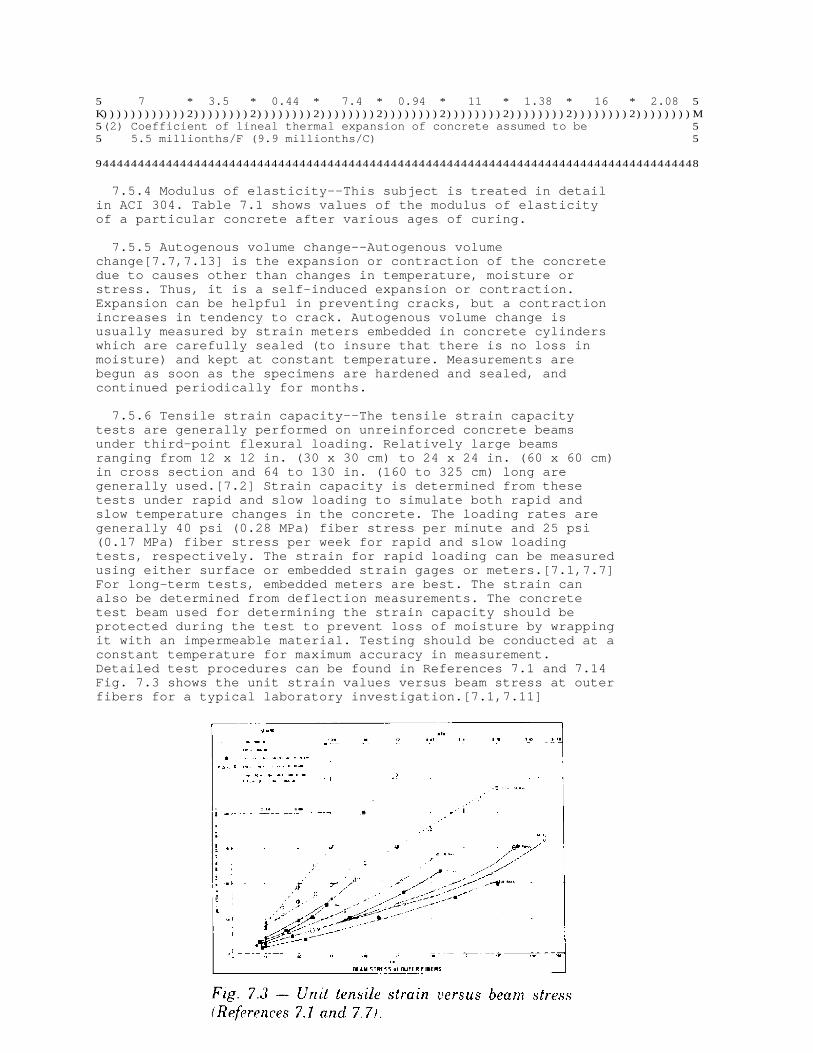
5 7 * 3.5 * 0.44 * 7.4 * 0.94 * 11 * 1.38 * 16 * 2.08 5K))))))))))))2))))))))2))))))))2))))))))2))))))))2))))))))2))))))))2))))))))2))))))))M 5(2) Coefficient of lineal thermal expansion of concrete assumed to be 5 5 5.5 millionths/F (9.9 millionths/C) 5 94444444444444444444444444444444444444444444444444444444444444444444444444444444444448
7.5.4 Modulus of elasticity--This subject is treated in detailin ACI 304. Table 7.1 shows values of the modulus of elasticityof a particular concrete after various ages of curing.
7.5.5 Autogenous volume change--Autogenous volumechange[7.7,7.13] is the expansion or contraction of the concretedue to causes other than changes in temperature, moisture orstress. Thus, it is a self-induced expansion or contraction.Expansion can be helpful in preventing cracks, but a contractionincreases in tendency to crack. Autogenous volume change isusually measured by strain meters embedded in concrete cylinderswhich are carefully sealed (to insure that there is no loss inmoisture) and kept at constant temperature. Measurements arebegun as soon as the specimens are hardened and sealed, andcontinued periodically for months.
7.5.6 Tensile strain capacity--The tensile strain capacitytests are generally performed on unreinforced concrete beamsunder third-point flexural loading. Relatively large beamsranging from 12 x 12 in. (30 x 30 cm) to 24 x 24 in. (60 x 60 cm)in cross section and 64 to 130 in. (160 to 325 cm) long aregenerally used.[7.2] Strain capacity is determined from thesetests under rapid and slow loading to simulate both rapid andslow temperature changes in the concrete. The loading rates aregenerally 40 psi (0.28 MPa) fiber stress per minute and 25 psi(0.17 MPa) fiber stress per week for rapid and slow loadingtests, respectively. The strain for rapid loading can be measuredusing either surface or embedded strain gages or meters.[7.1,7.7]For long-term tests, embedded meters are best. The strain canalso be determined from deflection measurements. The concretetest beam used for determining the strain capacity should beprotected during the test to prevent loss of moisture by wrappingit with an impermeable material. Testing should be conducted at aconstant temperature for maximum accuracy in measurement.Detailed test procedures can be found in References 7.1 and 7.14Fig. 7.3 shows the unit strain values versus beam stress at outerfibers for a typical laboratory investigation.[7.1,7.11]

In the preliminary studies of temperature and constructioncontrol plans for mass concrete projects, approximate methods forestimating tensile strain capacity under rapid and slow loadingsgiven in References 7.5 and 7.20 may be used.
7.6--Artificial cooling by embedded pipe systems
The overall program for cooling concrete, including importantfield control criteria, should be determined during the designstage. Precooling concrete prior to placement is accomplished bya variety of methods, including cooling all ingredients of themix and using small ice particles as a replacement of part of themixing water. Post-cooling of concrete is accomplished bycirculating cool liquids (usually water) through pipes embeddedin the concrete. Studies made during the design stage will establish such itemsas lift height, pipe spacing, water temperature and rate of flow,acceptable rate of temperature drop (for both rapid and slowdrops), and approximate duration of cooling.
In general, the duration of cooling and the heat removed by thepipe cooling should be sufficient to insure that a secondaryinternal temperature rise in the mass does not exceed the primaryrise. It is, however, important that steep cooling gradients,which can result in cracking the mass, be avoided. This isparticularly true in smaller masses where circulation of coolingwater should be stopped when the maximum temperature has beenreached and just begins to drop. A vulnerable location in pipecooling systems is centered at the cooling coils where sharpgradients and cracking can be induced if termination of coolingwater circulation is not timely.
Resistance thermometers should be used in sufficient numbers topermit adequate monitoring and control of the internal concretetemperatures.
Construction drawings should show basic pipe layout and spacingincluding minimum spacing, and the layout at dam faces,transverse construction joints, interior openings and in sloping,partial, and isolated concrete lifts. A pipe layout for a typicalconcrete lift is shown in Fig. 7.4.
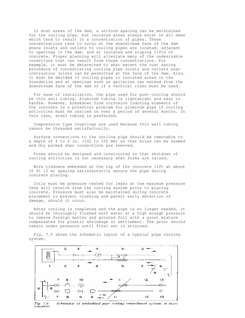
In most areas of the dam, a uniform spacing can be maintainedfor the cooling pipe, but isolated areas always exist in all damswhich tend to result in a concentration of pipes. Theseconcentrations tend to occur at the downstream face of the damwhere inlets and outlets to cooling pipes are located, adjacentto openings in the dam, and at isolated and sloping lifts ofconcrete. Proper planning will alleviate many of the undesirableconditions that can result from these concentrations. Forexample, it must be determined to what extent the cost savingprocedure of concentrating cooling pipe inlets and outlets nearcontraction joints can be permitted at the face of the dam. Also,it must be decided if cooling pipes to isolated areas in thefoundation and at openings such as galleries can extend from thedownstream face of the dam or if a vertical riser must be used.
For ease of installation, the pipe used for post-cooling shouldbe thin wall tubing. Aluminum tubing is lightweight and easy tohandle. However, breakdown from corrosion inducing elements ofthe concrete is a potential problem for aluminum pipe if coolingactivities must be carried on over a period of several months. Inthis case, steel tubing is preferred. Compression type couplings are used because thin wall tubingcannot be threaded satisfactorily.
Surface connections to the cooling pipe should be removable toa depth of 4 to 6 in. (102 to 152 mm) so that holes can be reamedand dry packed when connections are removed.
Forms should be designed and constructed so that shutdown ofcooling activities is not necessary when forms are raised.
Wire tiedowns embedded at the top of the concrete lift at about10 ft (3 m) spacing satisfactorily secure the pipe duringconcrete placing.
Coils must be pressure tested for leaks at the maximum pressurethey will receive from the cooling system prior to placingconcrete. Pressure must also be maintained during concreteplacement to prevent crushing and permit early detection ofdamage, should it occur.
After cooling is completed and the pipe is no longer needed, itshould be thoroughly flushed with water at a high enough pressureto remove foreign matter and grouted full with a grout mixturecompensated for plastic shrinkage or settlement. The grout shouldremain under pressure until final set is attained.
Fig. 7.5 shows the schematic layout of a typical pipe coolingsystem.

Sight flow indicators should be installed at the end of eachembedded pipe coil to permit ready observance of cooling waterflow. In addition to regular observance of flows, watertemperatures and pressures and concrete temperatures should beobserved and recorded at least once daily while the lift is beingcooled.
The refrigeration plant for cooling water may be centrallylocated, or several smaller complete portable plants may be usedto permit moving the refrigeration system as the dam progressesupward. Sufficient standby components, equal in capacity to thelargest individual refrigeration units should be provided.
7.7--Summary--Basic considerations for construction controls andspecifications
The construction controls and specifications for mass concretemust be such that the structures will be safe, economical,durable, and pleasing in appearance. Each of these requirementsin turn affects the crack resistance. Safety will be assured ifthe concrete has sufficient strength and continuity (absence ofcracks). Economy will depend upon such features as the bestchoice of aggregates, adequate but not excessive temperaturecontrol, low cement content, etc. Durability will depend upon thequality of the concrete, exposure conditions, and freedom fromchemical reactions of a deteriorating nature. Pleasing appearancewill come from good workmanship, freedom from cracks and stains,absence of leakage and leaching, etc. The importance of acomprehensive materials test program to establish necessarycontrol prior to preparation of construction controls andspecifications cannot be over-emphasized.
7.7.1 Safety
7.7.1.1 Safety against crushing-concrete strength. A strengthshould be specified which will provide an adequate factor ofsafety against crushing of the concrete. The "nominal" factor ofsafety is merely the compressive strength divided by the maximumstress to be expected in the structure. However, neither thestrength nor the maximum stress can be accurately determined. Thestrength is usually derived from tests on cylindrical specimenswhich are not completely representative of the structure. Themaximum stress is usually taken as the design stress which isbased upon assumed concrete properties. For such reasons, it isconsidered good practice to use a safety factor as high as threeor four, meaning that the strength should be three or four timesthe expected maximum stress. The 90-day strength is often usedand is derived from tests of job cylinders. Since the cylindersare made from wet screened concrete, the measured strength iscorrected to a mass-concrete equivalent by applying a reductionfactor of about 0.80 for typical conditions. For specific data onappropriate reduction factors, the reader should refer to theU.S. Bureau of Reclamation, Concrete Manual 8th Edition.[7.16]
The "factor of safety," as defined above, is subject to anumber of additional factors which, more or less, balance oneanother. Since the average strength of the job cylinders is used,half of the tests will be weaker. The strength at 90 days is notthe ultimate strength. There can be a large gain after 90 daysdepending upon the composition of the cement. However, even a"factor of safety" of three is far more than enough to cover any
likely differences between plus and minus corrections.
For interior concrete, the lowest practical strength should bespecified so as to reduce the cement content. This, in turn, willreduce the heat of hydration and the consequent thermal stresses,thus increasing the crack resistance of the concrete. More thanthe necessary amount of cement is detrimental rather thanadvantageous. 7.7.1.2 Safety against sliding. Sound, uncracked concreteprovides a very large factor of safety against sliding. However,hardened horizontal lift joints may impair the safety. Therefore,the specifications should require care in the preparation of liftsurfaces and in the placement and compaction of concrete thereon.Also, the lift surfaces should slope slightly upward toward thedownstream edge (in the case of a dam) such that the downstreamedge is higher than the upstream edge. It is not necessary to usea mortar layer on lift surfaces prior to the placement of thenext lift.
7.7.2 Economy--Many factors which affect the economy alsoaffect crack resistance. For example, the least expensiveaggregate may have bad thermal properties and thus requireexpensive temperature control to prevent cracking. The aggregatewhich makes concrete of highest tensile-strain capacity mayincrease the water requirement and, therefore, also the cementrequirement, thus offsetting the benefits of high straincapacity. Some of the factors which affect economy are discussedbelow.
7.7.2.1 Selection of aggregate. Aggregate should be chosenthat makes good concrete with the lowest overall cost. If naturalaggregate near the site has unfavorable properties for crackprevention, crushing to increase crack resistance may be aneconomical expedient because of the consequent saving intemperature control. When crushing is either advantageous ornecessary, rock which has the most favorable properties should bechosen. The rock should have a low coefficient of thermalexpansion, a low modulus of elasticity, and it should produceparticles of good shape and surface texture. All of these factorsare important in increasing the resistance of the concrete tocracking.
7.7.2.2 Aggregate size. The largest maximum size ofaggregate, up to approximately 6 in. (150 mm) in diameter, shouldbe specified as can be placed properly in the structure, exceptfor concrete which must resist high-velocity water flow. Largeraggregate permits the use of less water and cement per cubicyard, resulting in savings in both the amount of cement and theamount of temperature control necessary for required crackresistance.
7.7.2.3 Water content. A reduction in the water content ofconcrete permits a corresponding reduction in the cement content.The concrete with less water and cement is superior in many ways:it undergoes less temperature change, less drying shrinkage, andas a result is more durable and crack resistant. As indicated inSection 7.4, minimum water content can be achieved by specifyingadequately powerful vibrators which permit the use of low slumpconcrete, by using a water-reducing agent when appropriate, andby producing and placing the concrete at low temperature.
7.7.2.4 Use of pozzolan. In most locations, good pozzolanssuch as fly ash are available, and they can be used to replace aportion of the cement. This can result in a considerable savingin cost, and possibly more important, it can reduce the heatgeneration and improve the resistance against cracking. Anotheradvantage of using pozzolan is that when used in adequateamounts, it reduces the expansion due to reactive aggregates whensuch are encountered. The appropriate amount of pozzolan for areactive aggregate should be based upon test data obtained withthe pozzolan and cement being used.
7.7.3 Durability--Durability of concrete is closely related tothe exposure conditions. In tropical climates, for example, theremay be no deteriorating influences acting on the concrete exceptthat which is subject to high-velocity water flow. For the mainstructure in such a case, any concrete which has the requiredstrength can be expected to last indefinitely, and the cementcontent should be kept low to minimize heat generation andresultant potential cracking.
Where the climate is severe, such that there is much freezingand thawing in winter, the water-cement ratio of surface concreteshould be kept lower than that necessary for strength alone. Airentrainment should be mandatory. For any concrete which might besubject to both alternations of freezing and water pressure, thewater-cement ratio should be less than 0.40 by weight. The effectof the rich boundary concrete on thermally induced cracking willbe minimized by keeping the thickness of the boundary layer to aminimum, probably 2 ft (0.6 m) or less.
7.7.4 Control of cracking--A detailed discussion of the controlof cracking in massive structures has been presented in thischapter. With proper planning and execution, the procedurespresented will serve as useful tools in developing a crackcontrol program for mass concrete structures.
References
[7.1] Houk, Ivan E., Jr.; Paxton, James A.; and Houghton,Donald L., "Prediction of Thermal Stress and Strain Capacity ofConcrete by Tests on Small Beams," ACI JOURNAL, Proceedings V.67, No. 3, Mar. 1970, pp. 253-261.
[7.2] Houghton, Donald L., "Determining Tensile Strain Capacityof Mass Concrete," ACI JOURNAL, Proceedings V. 73, No. 12, Dec.1976, pp. 691-700.
[7.3] Wilson, E. L., "The Determination of Temperatures withinMass Concrete Structures," Report No. 68-17, StructuralEngineering Laboratory, University of California, Berkeley, Dec.1968. [7.4] Polivka, R. M., and Wilson, E. L., "Finite ElementAnalysis of Nonlinear Heat Transfer Problems," Report No. UC SESM76-2, Department of Civil Engineering, University of California,Berkeley, June 1976.
[7.5] Sandhu, R. S.; Wilson, E. L.; and Raphael, J. M.,"Two-Dimensional Stress Analysis with Incremental Constructionand Creep," Report No. 67-34, Structural Engineering Laboratory,

University of California, Berkeley, Dec. 1967.
[7.6] Liu, Tony C.; Campbell, R. L.; and Bombich, A. A.,"Verification of Temperature and Thermal Stress Analysis ComputerPrograms for Mass Concrete Structures," Miscellaneous Paper No.SL-79-7, U.S. Army Engineer Waterways Experiment Station,Vicksburg, Apr. 1979.
[7.7] Houghton, Donald L., "Concrete Volume Change for DworshakDam," Proceedings, ASCE, V. 95, PO2, Oct. 1969, pp. 153-166.
[7.8] "Method of Test for Thermal Diffusivity of MassConcrete," (CRD-C 37-73), Handbook for Concrete and Cement, U.S.Army Corps of Engineers, Vicksburg, Dec. 1973, 3 pp.
[7.9] "Method of Test for Coefficient of Linear ThermalExpansion of Concrete" (CRD-C 39-55), Handbook for Concrete andCement U.S. Army Corps of Engineers, Vicksburg, 1939, 2 pp.
[7.10] "Method of Test for Coefficient of Linear ThermalExpansion of Coarse Aggregate, Strain Gage Method," (CRD-C125-63), Handbook for Concrete and Cement, U.S. Army Corps ofEngineers, Vicksburg, June 1963, 5 pp.
[7.11] Symposium on Creep of Concrete, SP-9, American ConcreteInstitute, Detroit, 1964, 160 pp.
[7.12] McCoy, E. E., Jr.; Thorton, H. T.; and Allgood, J. K.,"Concrete Laboratory Studies, Dworshak (Bruce's Eddy) Dam, NorthFork Clearwater River Near Orofino, Idaho: Creek Tests,"Miscellaneous Paper No. 6-613, Report 2, U.S. Army EngineerWaterways Experiment Station, Vicksburg, Dec. 1964.
[7.13] Houk, Ivan E., Jr.; Borge, Orville E.; and Houghton,Donald, "Studies of Autogenous Volume Change in Concrete forDworshak Dam," ACI JOURNAL, Proceedings V. 66, No. 7, July 1969,pp. 560-568.
[7.14] McDonald, J. E.; Bombich, A. A.; and Sullivan, B. R.,"Ultimate Strain Capacity and Temperature Rise Studies, TrumbullPond Dam," Miscellaneous Paper C-72-2U, U.S. Army EngineerWaterways Experiment Station, Vicksburg, Aug. 1972. [7.15] Liu, Tony C., and McDonald, James E., "Prediction ofTensile Strain Capacity of Mass Concrete," ACI JOURNAL,Proceedings V. 75, No. 5, May 1978, pp. 192-197.
[7.16] Concrete Manual, 8th Edition, U.S. Bureau ofReclamation, Denver, 1975, 627 pp.
CHAPTER 8--CONTROL OF CRACKING BY CORRECT CONSTRUCTION PRACTICES*
(* Principal author: Lewis H. Tuthill.)
8.1--Introduction
Construction practices, as used in this chapter, includedesigns, specifications, materials, and mix considerations, aswell as on-the-job construction performance. Before discussingcontrol of construction practices which affect cracking, it is
worthwhile to mention the basic cause of cracking. It isrestraint. If all parts of the concrete in a concrete structureare free to move as concrete expands or contracts, particularlythe latter, there will be no cracking due to volume change.
Obviously, however, all parts of concrete structures are notfree, and inherently, cannot be free to respond to the samedegree to volume changes. Consequently, differential strainsdevelop and tensile stresses are induced. When these differentialresponses exceed the capability of the concrete to withstand themat that time, cracking occurs. This points to the importance ofprotecting new concrete for as long as practicable from the lossof moisture or a drop in temperature. These considerations mayresult in stresses capable of causing cracks at an early age butwhich might be sustained at greater maturity. Preferably,concrete should have a high tensile strain-to-failure capacity.This is influenced greatly by the aggregate, and a low modulus ofelasticity in tension is desirable.
8.2--Restraint
Restraint exists in many circumstances under which thestructure and its concrete elements must perform. Typicalexamples will illustrate how restraint will cause cracking, ifthe concrete is not strong enough to withstand the tensilestresses developed.
8.2.1--A wall or parapet anchored along its base to thefoundation or to lower structural elements less subject orresponsive to volume change, will be restrained from shrinkingwhen its upper portions shorten due to drying or cooling.Cracking is usually inevitable unless contraction joints (or atleast grooves of a depth not less than 10 % of the wall thicknesson both sides, in which the cracks will occur and be hidden) areprovided at intervals ranging from one (for high walls) to three(for low walls) times the height of the wall.
8.2.2--Exterior and interior concrete, particularly in heaviersections, will change temperature or moisture content atdifferent rates and to different degrees. When this happens, theinterior concrete restrains the exterior concrete from shrinking,and tensile strains develop which may cause the exterior tocrack. This occurs when the surface cools, while the interior isstill warm from the heat of hydration, or when the surfaceconcrete dries faster than the interior concrete. As notedearlier, it is often feasible to protect the surface for a timeat early ages so that such stress-inducing differentials cannotdevelop before the concrete is strong enough to withstand thestrain without cracking.
8.2.3--Acting similarly to the interior concrete in theforegoing example, temperature reinforcement can restrain theshrinkage of surface concrete, but more and narrower cracks mayresult.
8.2.4--Restraint will occur at sharp changes in section, sincethe effect of temperature change or drying shrinkage will bedifferent in the two sections. If feasible a contraction jointcan be used to relieve the restraint.
8.2.5--Restraint of flat work results from anchorage of slab

reinforcement in perimeter slabs or footings. When a slab is freeto shrink from all sides toward its center, there is a minimum ofcracking. Contraction joints and perimeter supports should bedesigned accordingly (see Section 3.5.3).
8.2.6--Wall slabs, and tunnel linings placed against theirregular surface of a rock excavation are restrained from movingwhen the surface expands or contracts in response to changes intemperature or moisture content. As discussed in Section 8.2.1,closely spaced contraction joints or deep grooves must beprovided to prevent or hide the cracks which often disfigure suchsurfaces. In tunnel linings, the shrinkage in the first few weeksis primarily thermal, and the use of cold concrete (50 F or 10 C)has reduced cracking materially. By the time drying issignificant, the concrete lining is much stronger and better ableto resist shrinkage cracking. However, circumferential cracks intunnel linings and other cast-in-place concrete conduits and pipelines can be greatly reduced in number and width. As shown in theBureau of Reclamation Concrete Manual,[81] this can be done if abulkhead is used to prevent air movement through the tunnel, andshallow ponds of water are placed in the invert as soon aspossible after lining, and left until the tunnel goes intoservice. If the tunnel carries water, there will be no furtherdrying shrinkage. If it does not, the concrete will have becomemuch stronger in the humid environment and will be better able toresist shrinkage-induced tensile stresses
8.2.7--The typical examples presented above clearly indicatethat many crack control procedures must be considered by theengineer during design. While proper construction performance cancontribute a great deal (as will be discussed below), thecontractor cannot be expected to utilize the best procedures,unless these procedures are included in the designs andspecifications on which the bid price is based.
8.3--Shrinkage
The following sections discuss the major causes of shrinkage,which is a key contributor to the formation of cracks inconcrete.
8.3.1 Effect of water content--The greater the water content ofconcrete, the more it will shrink on drying. Such a hypothesis isclearly indicated in Fig. 3.2, as well as in Reference 8.1. Theuse of the lowest practical slump is important. Of majorimportance is the selection of mix proportions that require theleast amount of water per cubic yard for the desired concretestrength. This means avoiding over-sanded mixes (the richer theconcrete, the coarser the sand should be and the less thereshould be of it in the mix); using the largest maximum aggregatesize practical; using aggregate with the most favorable shape andgrading conducive to best workability; and using well-graded sandwith a minimum of fines passing the 100-mesh and free of clay,such that its sand equivalent value is not less than 80 percentAASHTO T176.
Contrary to common belief, increasing the cement content ofconcrete, per se, does not necessarily cause an increase inshrinkage. This is because the water requirement of concrete doesnot change much with a change in cement content. Drying shrinkageis proportional to water content (Fig. 3.2), not cement content.

Moreover, the reduction of the amount of fine aggregate tocompensate for the added cement, in accordance with correctprinciples of concrete proportioning, will offset any tendency toincrease the water requirement.
8.3.2 Surface drying--Surface drying will ultimately occurexcept when the surface is submerged or backfilled. It will causeshrinkage strains of up to 600 millionths or more. The amount ofshrinkage cracking depends on 1. how dry the surface concretebecomes, 2. how much mixing water was in the concrete, 3. thecharacter and degree of restraint involved, and 4. theextensibility of the concrete. The extensibility represents howmuch the concrete can be strained (stretched), without exceedingits tensile strength and is the sum of creep plus elastic straincapacity. The latter is largely related to the composition of theaggregate and may vary widely. Typically, some concretes ofhighly quartzitic gravels have a low strain capacity and a highmodulus of elasticity, while some concretes of granitic andgneissic aggregate have a high strain capacity and a low modulusof elasticity. Concretes having a low strain capacity are muchmore sensitive to shrinkage due to drying (and to drop intemperature) and will be subject to a greater amount of cracking.
Accordingly, as mentioned in connection with tunnel linings andconduits, a prime objective of crack control procedures is tokeep the concrete wet as long as feasible, so that it will havetime to develop more strength to resist cracking forces. Theimportance of this will vary with the weather and the time ofyear. Cold concrete (below 50 F, 10 C) dries very slowly,provided the relative humidity is above 40 percent. At somedepth, concrete loses moisture slowly, as shown in Fig. 3.5.Where surface drying may be rapid, more care must be devoted touninterrupted curing to get good surface strength. Crackingstresses will be further reduced by creep, if the surface isprevented from drying quickly at the end of the curing period. Toaccomplish this, the wet curing cover can be allowed to remainseveral days without wetting after the specified curing period(preferably 7 to 10 days), until the cover and the concrete underit appear to be dry. If job conditions are likely to be such thatthese measures will be worthwhile, they should be required in thespecifications for the work.
8.3.3 Plastic shrinkage--Plastic shrinkage cracks occur mostcommonly, and objectionably, in the surfaces of floors and slabswhen the ambient job conditions are so arid that moisture isremoved from the concrete surface faster than it is replaced bybleed water from below. These cracks occur prior to finalfinishing and commencement of the curing process. As the moistureis removed, the surface concrete contracts, resulting in tensilestresses in the essentially strengthless, stiffening plasticconcrete, that cause short random cracks or openings in thesurface. These cracks are usually rather wide at the surface butonly a few inches in depth. The cracks generally range from a fewinches to a few feet in length and are a few inches to two feetapart.
Sometimes plastic shrinkage cracks appear early enough to beworked out in later floating or first trowelling operations. Whenthis is successful, it is advisable to postpone these operationsas long as possible to get their maximum benefit without therecurrence of cracking.

In other cases, an earlier than normal floating may destroy thegrowing tension by reworking the surface mortar and preventplastic cracking that would otherwise occur. At the firstappearance of cracking while the concrete is still responsive, avigorous effort should be made to close the cracks by tamping orbeating with a float. If firmly closed, they will be monolithicand are unlikely to reappear. However, they may reappear if theyare merely trowelled over. In any event, curing should be startedat the earliest possible time.
Conditions most likely to cause plastic shrinkage cracking arehigh temperatures and dry winds. Accordingly, specificationsshould stipulate that effective moisture control precautionsshould be taken to prevent a serious loss of surface moistureunder such conditions. Principal among these precautions are theuse of fog (not spray) nozzles to maintain a sheen of moisture onthe surface between the finishing operations. Plastic sheetingcan be rolled on and off before and after floating, preferablyexposing only the area being worked on at that time. Leasteffective but helpful are certain sprayed mono-molecular filmswhich inhibit evaporation. Windbreaks are desirable, and as such,it is desirable to schedule flatwork after the walls are up (ACI305R, ACI 302.1R).
Other helpful practices that may augment the bleeding andcounteract the excessive loss of surface moisture, are 1. using awell dampened sub-grade, 2. cooling the aggregates by dampeningand shading them, and 3. using cold mixing water or chipped iceas mixing water to lower the temperature of the fresh concrete.
8.3.4 Surface cooling--Surface cooling will shrink the surfaceof average unrestrained concrete about 10 millionths for each degC (5.5 millionths per deg F) the temperature goes down. Thisamounts to 9 mm in a 30 m length with a drop of 30 C (1/3 in. in100 ft with a drop of 50 F). The amount of shrinkage is reducedby restraint and creep, but tensile stresses are induced. Theearlier the age and the slower the rate at which cooling ordrying occur, the lower the tensile stresses will be. This is dueto the relaxing influence of creep, which imparts moreextensibility to concrete at early ages.
In ordinary concrete work, the winter protection required forthe development of adequate strength will prevent the mostcritical effects of cooling. The system of contraction joints andgrooves previously discussed for control of shrinkage crackingwill serve the same purpose against substantial later drops insurface temperature. In addition to Chapter 7 of this report,Chapters 4 and 5 of ACI 207.1R discuss temperature controls formass concrete to minimize the early temperature differencesbetween interior and exterior concrete. Primarily, these controlslower the interior temperature rise caused by the heat ofhydration by using 1. no more cement than necessary, 2. pozzolansfor a portion of the cement, 3. water reducing admixtures, 4.air-entrainment, 5. large aggregate, 6. low slump, and 7. lastbut by no means least, where at all practicable, chipped ice formixing water to reduce the temperature of the fresh concrete asmuch as possible. See Fig 3.4 and Fig. 3.1 of ACI 207.2R. At notime should forms be removed to expose warm surfaces to lowtemperatures. As mentioned in Section 8.3.2, the extensibility,or strain the concrete will withstand before tensile failure, isa function of the aggregate and should be evaluated, especially
on larger projects. What applies to one will not necessarilyapply to another.
8.4--Settlement
Settlement or subsidence cracks develop while concrete is inthe plastic stage, after the initial vibration. They are not dueto any of the causes discussed above, but are the natural resultof heavy solids settling in a liquid medium. Settlement cracksoccur opposite rigidly supported horizontal reinforcement, formbolts or other embedments. Sometimes concrete will tend to adhereto the forms. A check will appear at these locations, if theforms are hot at the top or are partially absorbent. Cracks oftenappear in horizontal construction joints and in bridge deck slabsover reinforcing or form bolts with only a few inches cover. Thecracks in bridge decks can be reduced by increasing the concretecover.[8.2] Properly executed late revibration can be used toclose settlement cracks and improve the quality and appearance ofthe concrete in the upper portion of such placements, even thoughsettlement has taken place and slump has been lost.
8.5--Construction
A great deal can be done during construction to minimizecracking, or in many cases to eliminate it. But, as noted inSection 8.2.7, such actions must be required by thespecifications and by the engineering forces which administerthem. Such actions include the following:
8.5.1 Concrete aggregates--The aggregate should be one whichmakes concrete of high strain capacity, if reasonably available(see Section 7.2). Fine and coarse aggregates have to be cleanand free of unnecessary fine material, particularly clays. Thesand should have a sand equivalent value in excess of 80 percent,and this should be verified frequently (AASHTO T176). The sandshould have sufficient time in storage for the moisture contentto stabilize at a level of less than 7 percent on an oven-drybasis.
8.5.2 Expansive cement--Expansive cement can be used to delayshrinkage during the setting of concrete in restrained elementsreinforced with the minimum shrinkage steel required by ACI 318.The principal property of these cements is that the expansioninduced in the concrete while setting and hardening is designedto offset the normal drying shrinkage. With correct usage(particularly with early and ample water curing on which maximumexpansion depends), the distance between joints can sometimes betripled without increasing the level of shrinkage cracking.Details on the types and correct usage of shrinkage compensatingcements are given in ACI 223.
8.5.3 "Non-shrink" grout, mortar, or concrete--Ordinarily, thesolids in grout, mortar, and concrete mixtures will settle beforehardening, and water will rise, some of it to the top surface.This settlement can be objectionable if a space is to be filledup tightly without leaving a void at the top, such as undermachine bases. Measures taken to prevent such subsidence haveproduced what is known in the trade as "Non-shrink" grout,mortar, or concrete. Some of the materials merely preventsettlement; others in addition, provide a slight expansion as themixture hardens.

The most widely used materials contain unpolished aluminumpowder. These should contain no stearates, palmitates, or fattyacids. In an alkaline solution, such as exists in portland cementmixtures, the aluminum reacts to form aluminum oxide andhydrogen. The hydrogen gas tends to expand the mixture and thusprevents subsidence and may even cause expansion. The amount ofaluminum powder used varies widely with conditions, but isusually in the neighborhood of 0.005 to 0.01 percent by weight ofthe cement. It is not possible to specify an exact percentagebecause the amount to be used varies with such factors astemperature, alkali content of the cement, and the richness ofthe mix. Therefore, it is advisable to make trial mixes withvarious percentages of aluminum powder to find which percentagegives the desired (slight) expansion under the prevailingconditions. The amount of aluminum powder used is so small thatit is advisable to dilute it by blending with 50 parts of sand orfly ash. This diluted mixture will have enough bulk so that itcan be easily measured and properly dispersed in the mix.
Among the admixtures that merely prevent settlement, a numberof different mechanisms are in operation. One commercial grout isso highly accelerated that it starts setting before settlementtakes place. Another is composed of organic gelling compounds ofsoluble cellulose which increase in viscosity so that the solidparticles remain in suspension. Still another contains a form ofcarbon with a very large surface area. In the dry form, itcontains a large amount of adsorbed air, which is releasedgradually into the mix producing an expansion.
Gas forming agents and air releasing agents produce the samenet effect, although all grouts, mortars and concretes employingthese agents have no expansive properties after hardening, andhave a drying shrinkage at least equal to similar plain grouts,mortars and concretes not employing them. Grouts which expand (ifunconfined) after hardening can function as nonshrink grouts, asopposed to grouts that expand only in the plastic state and latersuffer drying shrinkage.
Among the commercial admixtures, there is one containing ametallic aggregate which, in addition to opposing settlementduring hardening, provides a modest expansion after hardening.This acts to hold the grout tightly up under base plates, etc.,and also tends to offset the effect of drying shrinkage.
Where feasible, the problem of settlement can be solved by theuse of dry tamped mortar, instead of a fluid grout or mortar.Grout mixed in a colloid mill will not readily settle.
It should be noted that prepackaged "Non-shrink" grouts, likeany portland cement grouts and mortars, are subject to shrinkageif exposed to drying and may deteriorate and lose serviceabilityif exposed to an aggressive environment (weathering, salt spray,etc.).
8.5.4 Handling and batching--Should be done with all practicalcare to avoid contamination, overlap of sizes, segregation, andbreakage, so that extra amounts of fines are not needed in themixes to account for variations in grading without a serious lossof workability. This is best done by finish screening and rinsingas a combination of coarse aggregate sizes goes to the batchplant bins. Every effort should be made to uniformly batch and

mix the concrete so that there will be a minimum of troublesomevariation in slump and workability. These, invariably, lead todemands for a greater margin of workability, with more sand andmore water in the concrete.
8.5.5 Excessive workability--Whether it is achieved withunneeded higher slump, oversanding, small aggregate, or evenhigher air content (which may reduce strength), is always popularand in demand on the job. It must be discouraged if the bestconcrete for the work (having adequate workability with properhandling and vibration, and having minimum shrinkage factors) isto be obtained.
8.5.6 Cold concrete--Cold concrete, when combined with factorsto reduce water and cement content to a practical minimum, willreduce temperature differentials which cause cracking. Coldconcrete is particularily useful for massive concretes. Itrequires less mixing water and thus reduces drying shrinkage. Inwarm weather it expedites the work by reducing slump loss,increasing pumpability, and by improving the response tovibration. It is obtained by substituting chipped ice for all ora part of the batched mixing water. In cold weather, concrete isnaturally cold and every effort should be made to use it as coldas possible without inviting damage from freezing. It ispointless to expect to protect surfaces, edges, and corners byplacing needlessly warm concrete in cold weather. Thesevulnerable parts must be protected with insulation or protectiveenclosures (ACI 306R).
8.5.7 Revibration--When done as late as the formed concretewill respond to the vibrator, will eliminate cracks and checkswhere something rigidly fixed in the placement prevents a part ofthe concrete from settling with the rest of it. Settlement cracksare most apparent in the upper part of wall and column placementswhere revibration can be readily used. Deep revibration correctscracks caused by differential settlement around blockout andwindow forms, and where slabs and walls are placedmonolithically.
8.5.8 Finishing--Flatwork finishing can make a great differencein the degree of freedom from all types of cracking (ACI 302.1R).Low-slump concrete should be used. More than a 3 in. (76 mm)slump is rarely necessary except perhaps in very hot weather inwhich both slump and moisture are lost quite rapidly. Finishingshould not be done in the presence of surface water. Precautions(see Section 8.3.4) should be taken to prevent plastic shrinkage.Any required marking and grooving should be carefully cut to thefull depth specified. Curing should be prompt, of full duration,and the wet cover should be allowed to dry before it is removed.
8.5.9 Curing and protection--Newly placed concrete must bebrought to a level of strength maturity and protected from lowtemperatures and drying conditions which would otherwise causecracking. The curing and protection should not be discontinuedabruptly. If the new concrete is given a few days to graduallydry or cool, creep will have an opportunity to reduce thepossibility of cracking when the curing and protection are fullydiscontinued.
8.5.10 Miscellaneous--Some items normally covered inspecifications (or certainly which should be covered where
appropriate) require special attention during constructionbecause of their potential effects on cracking.
1. Reinforcement and embedments must be properly positionedwith the designated thickness of cover in order to preventcorrosion, expansion and cracking.
2. Concrete should not be placed against hot reinforcement orforms.
3. Formwork support should be strong enough to be free of earlyfailures and distortion causing cracking.
4. Subgrade and other supports must not settle unevenly, toprevent cracks due to overstress in the structure. 5. Contact between aluminum and steel embedded in the concretemust be eliminated, particularly if use of calcium chloride ispermitted. If it is used, calcium chloride must be limited to theabsolute minimum (see Section 3.4.4).
6. Special care is needed in handling precast units to preventoverstress due to handling.
7. Unvented salamanders in cold weather (ACI 306R) or gasolineoperated equipment must be avoided where adequate ventilation isnot furnished, because of the danger of carbonation shrinkagesurface cracking.
8. Control joints, discussed in Sections 3.5.3 and 8.2.6, mustnot be omitted and grooves must be of the specified depth andwell within the maximum permitted spacing.
9. In addition to cleanliness of aggregate, stipulated inSection 8.3.1, any reactive elements of aggregate should beneutralized through the use of low alkali cement or a suitablepozzolan, or preferably both. Certain cherts and other expansiveaggregates and lignite can cause cracks at popouts. Jobspecifications should cover these aggregate properties andconstructors should ensure observance of these requirements.
10. Correct amounts of entrained air should be specified andused to prevent cracking due to freezing and thawing and exposureto calcium or sodium chloride.
8.6--Specifications to minimize drying shrinkage
Actions during construction to obtain the lowest possibledrying shrinkage must be supported by the specifications. Unlessbids are taken on this basis, the contractor cannot be expectedto provide other than ordinary materials, mixes, and procedures.The following items should be carefully spelled out in thespecifications.
8.6.1 Concrete materials--They can have an important influenceon drying shrinkage.
1. Cement should be Types I, II, V, or IS, preferably not TypeIII.
2. Aggregates favorable to low mixing water content are (a)

well graded, (b) well shaped (not elongated, flat, or splintery),and (c) free of clay, dirt, and excess fines.
3. Aggregate should consist of rock types which will producelow-shrinkage concrete (see Section 3.4.2). 4. Calcium chloride should be prohibited.
8.6.2 Concrete mixes--For least shrinkage, the mixproportioning should incorporate those factors that contribute tothe lowest water content. This means:
1. The largest practical maximum size of aggregate (MSA).
2. The lowest practical sand content.
3. The lowest practical slump.
4. The lowest practical temperature.
5. Less than half the smooth grading curve amount of smallcoarse aggregate, No. 4 to 3/8 or 3/4 in. (4.75 mm to 9.5 or 19mm), especially if it is crushed material.
8.6.3 Concrete handling and placing--Equipment (chutes, belts,conveyors, pumps, hoppers, and bucket openings) should be capableof working effectively with lower slump, larger MSA concretewherever it is appropriate and feasible to use. (It is cautionedthat too often, in order to expedite pumping, the actions takenare those which increase drying shrinkage and resultant cracking:more sand, more fines, more water, more slump, smaller aggregate.When pumping is to be permitted and freedom from shrinkagecracking is important, special emphasis must be placed onobtaining effective locations and an adequate number ofcontraction joints. Moreover, the use of pumping equipmentcapable of handling mixes favorable to least cracking should berequired.)
Vibrators should be the largest and most powerful that can beoperated in the placement.
Upper lifts of formed concrete should be revibrated as late asthe running vibrator will penetrate under its own weight.
8.6.4 Finishing--Finishing should follow the recommendations ofACI 302.1R to minimize or avoid all forms of surface cracking.
It is particularly important that flatwork joint grooves have adepth of at least 1/5 of slab thickness, but not less than 1 in.(25.4 mm) deep.
8.6.5 Forms--Forms should have ample strength to sustain strongvibration of low slump concretes.
Exposure of warm concrete surfaces to fast drying conditions orto low temperatures prior to curing, should be avoided duringform removal, if drying and thermal shrinkage cracking is to beprevented. 8.6.6 Contraction joints--Plans should include an adequatesystem of contraction joints to provide for shrinkage. Formed

grooves should be constructed in both sides of parapet,retaining, and other walls at the depth and spacings indicated inSec. 8.2.1.
8.6.7 Curing and protection--These procedures should insure thepresence of adequate moisture to sustain hydration and strengthdevelopment in the surface concrete. Rapid drying of the surfacesat the conclusion of the specified curing period should beavoided. Providing time for adjustment and gradual, slowelongation will minimize cracking.
Water curing should use a wet cover in contact with theconcrete surfaces. At the end of the wet curing period,preferably at least 7 days, the cover should be left in placeuntil it and the concrete surface appear to be dry, especially inarid weather.
In less arid areas and for interiors, the forms will provideadequate curing if exposed surfaces are protected from drying andprovided they can be left in contact with the concrete for atleast 7 days. Thereafter, the forms should be left on withloosened bolts long enough to allow the concrete surfaces to drygradually.
Ponding is not a desirable method of curing in an arid climatebecause of the quick drying that occurs when it is discontinued.
Because drying is slow and prolonged, a properly appliedsealing compound provides good curing for flatwork placed on awell-wetted subgrade and provides adequate curing for massivesections. In an arid climate, sealing compounds are not adequatefor thinner structural sections. When used on formed surfaces,they should be applied when the thoroughly wetted surface isstill damp but no longer wet.
8.7--Conclusion
As noted early in this chapter, it is the responsibility of theengineer to develop effective designs and clear and specificspecifications. To assure both the owner's and the engineer'ssatisfaction with the results, the engineer should have the ownerarrange for inspection by either the owner's personnel, theengineer, or a reliable professional inspection service who willinsure that the construction is performed on the same basis as itwas bid. Without the full and firm intent to confirm thespecified character and degree of performance, there is a seriouschance that undesirable results will be obtained. Without firminspection and controls, and a clear understanding of the jobrequirements by the contractor, it is likely that concrete willcontain more water than it should, finishing operations will beexpedited with the water brush (or hose), and curing will beinterrupted or abbreviated (not to mention other less obviousitems which influence the later appearance of unsightly cracks).When properly applied, the procedures discussed in this chaptercan be used to produce a high quality concrete with the leastprobable amount of cracking.
References
[8.1] Concrete Manual, 8th Edition, U.S. Bureau of Reclamation,
Denver, 1975, 627 pp.
[8.2] Dakhil, Fadh H.; Cady, Philip D.; and Carrier, Roger, E.,"Cracking in Fresh Concrete as Related to Reinforcement," ACIJOURNAL, Proceedings V. 72, No. 8, Aug 1975, pp. 421-428.
CHAPTER 9 -- REFERENCES
9.1--Recommended references
The documents of the various standards producing organizationsreferred to in this document are listed below with their serialdesignation.
American Association of State Highway and TransportationOfficials
T176 Plastic Fines in Graded Aggregate and Soils By Use of the Sand Equivalent Test
American Concrete Institute
201.2R Guide to Durable Concrete
207.1R Mass Concrete
207.2R Effect of Restraint, Volume Change, and Reinforcement on Cracking of Massive Concrete
211.1 Standard Practice for Selecting Proportions for Normal, Heavyweight, and Mass Concrete
212.1R/212.2R Admixtures for Concrete and Guide for Use of Admixtures in Concrete 223 Standard Practice for the Use of Shrinkage-Compensating Concrete
302.1R Guide for Concrete Floor and Slab Construction
304R Guide for Measuring, Mixing, Transporting, and Placing Concrete
305R Hot Weather Concreting
306R Cold Weather Concreting
308 Standard Practice for Curing Concrete
313 Recommended Practice for Design and Construction of Concrete Bins, Silos, and Bunkers for Storing Granular Materials

318 Building Code Requirements for Reinforced Concrete
340.1R Design Handbook in Accordance with the Strength Design Method of ACI 318-83, Volume 1--Beams, Slabs, Brackets, Footings, and Pile Caps (SP-17)
347.1R Precast Concrete Units Used as Forms for Cast-in-Place Concrete
504R Guide to Joint Sealants for Concrete Structures
517.2R Accelerated Curing of Concrete at Atmospheric Pressure--State of the Art
ASTM
C 512 Test Method for Creep of Concrete in Compression
E 399 Test Method for Plane-Strain Fracture Toughness of Metallic Materials
Comité Euro-International du Béton and Fédération Internationalede la Precontrainte
CEB-FIP Model Code for Concrete Structures The above publications may be obtained from the followingorganizations:
American Association of State Highway and TransportationOfficials333 North Capital St., N.W. Suite 225 Washington, DC 20001
American Concrete Institute P.O. Box 19150 Detroit, MI 48219
ASTM 1916 Race Street Philadelphia, PA 19103
Comité Euro-International du Béton and Fédération Internationale de la Precontrainte--English edition availablefrom:
British Cement Association Wexham Springs Slough SL# 6PL ENGLAND
9.2--Cited references
Cited references are provided at the end of each chapter.

This report was submitted to letter ballot of the committee whichconsists of 24 members; 21 were affirmative, 2 were not returned,and 1 abstained. It has been processed in accordance with theInstitute procedure and is approved for publication anddiscussion.
ACI Committee 224
Cracking
David Darwin, Chairman; Bernard L. Meyers, Past Chairman; R. S.Barneyback, Jr.; Eduardo Santos Basilio; Alfred G. Bishara; RoyW. Carlson; Noel J. Everard; J. Ferry-Borges; Peter Gergely;Donald L. Houghton; Paul H. Kaar; Tony C. Liu; J. P. Lloyd; LeRoyLutz; V. M. Malhotra; Dan Naus; Edward G. Nawy; Robert E.Philleo; Milos Polivka; Julius G. Potyondy; Robert E. Price;Ernest K. Schrader; Lewis H. Tuthill; Robert L. Yuan. The committee voting on the 1990 revisions was as follows:
Grant T. Halvorsen,* Chairman; Randall W. Poston, Secretary;Florian G. Barth; Alfred G. Bishara; Howard L. Boggs; Merle E.Brander; David Darwin;* Fouad H. Fouad;* Peter Gergely; WillHansen; Tony C. Liu; Edward G. Nawy; John D. Nicholas; HarryPalmbuam; Arnfinn Rusten; Andrew Scanlon; Ernest K. Schrader;Wimal Suaris; Lewis H. Tuthill;* Thomas D. Verti; Zenon A.Zielinski.
(* Members contributing to these revisions.)


