221093 E-Revolving Clamp Service - cascorp.com · Tools Required (metric), 4.1-2 11 Troubleshooting...
52
Cascade is a Registered Trademark of Cascade Corporation cascade T Manual Number 221093 ERVICE MANUAL E-Series Revolving Clamps S
Transcript of 221093 E-Revolving Clamp Service - cascorp.com · Tools Required (metric), 4.1-2 11 Troubleshooting...
Cascade is a Registered Trademark of Cascade CorporationcascadeT
Manual Number 221093
ERVICE MANUAL
E-SeriesRevolving Clamps
S
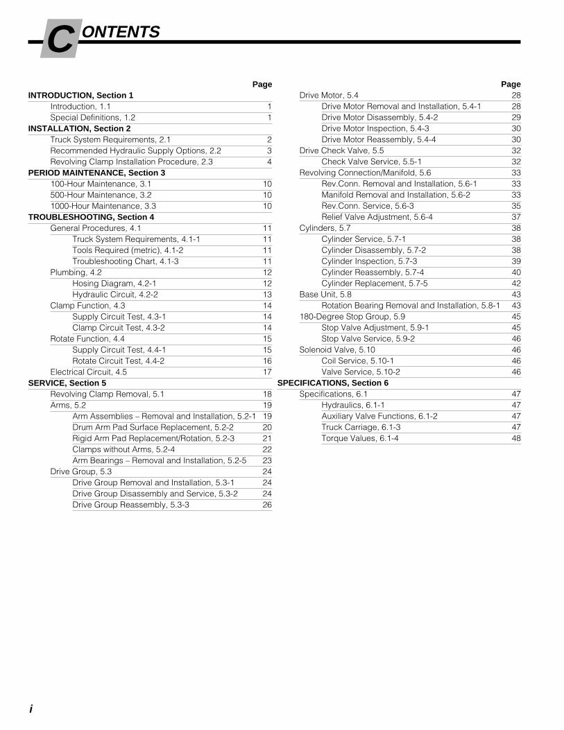
ONTENTSC
i
PageINTRODUCTION, Section 1
Introduction, 1.1 1Special Definitions, 1.2 1
INSTALLATION, Section 2Truck System Requirements, 2.1 2Recommended Hydraulic Supply Options, 2.2 3Revolving Clamp Installation Procedure, 2.3 4
PERIOD MAINTENANCE, Section 3100-Hour Maintenance, 3.1 10500-Hour Maintenance, 3.2 101000-Hour Maintenance, 3.3 10
TROUBLESHOOTING, Section 4General Procedures, 4.1 11
Truck System Requirements, 4.1-1 11Tools Required (metric), 4.1-2 11Troubleshooting Chart, 4.1-3 11
Plumbing, 4.2 12Hosing Diagram, 4.2-1 12Hydraulic Circuit, 4.2-2 13
Clamp Function, 4.3 14Supply Circuit Test, 4.3-1 14Clamp Circuit Test, 4.3-2 14
Rotate Function, 4.4 15Supply Circuit Test, 4.4-1 15Rotate Circuit Test, 4.4-2 16
Electrical Circuit, 4.5 17SERVICE, Section 5
Revolving Clamp Removal, 5.1 18Arms, 5.2 19
Arm Assemblies – Removal and Installation, 5.2-1 19Drum Arm Pad Surface Replacement, 5.2-2 20Rigid Arm Pad Replacement/Rotation, 5.2-3 21Clamps without Arms, 5.2-4 22Arm Bearings – Removal and Installation, 5.2-5 23
Drive Group, 5.3 24Drive Group Removal and Installation, 5.3-1 24Drive Group Disassembly and Service, 5.3-2 24Drive Group Reassembly, 5.3-3 26
Drive Motor, 5.4 28Drive Motor Removal and Installation, 5.4-1 28Drive Motor Disassembly, 5.4-2 29Drive Motor Inspection, 5.4-3 30Drive Motor Reassembly, 5.4-4 30
Drive Check Valve, 5.5 32Check Valve Service, 5.5-1 32
Revolving Connection/Manifold, 5.6 33Rev.Conn. Removal and Installation, 5.6-1 33Manifold Removal and Installation, 5.6-2 33Rev.Conn. Service, 5.6-3 35Relief Valve Adjustment, 5.6-4 37
Cylinders, 5.7 38Cylinder Service, 5.7-1 38Cylinder Disassembly, 5.7-2 38Cylinder Inspection, 5.7-3 39Cylinder Reassembly, 5.7-4 40Cylinder Replacement, 5.7-5 42
Base Unit, 5.8 43Rotation Bearing Removal and Installation, 5.8-1 43
180-Degree Stop Group, 5.9 45Stop Valve Adjustment, 5.9-1 45Stop Valve Service, 5.9-2 46
Solenoid Valve, 5.10 46Coil Service, 5.10-1 46Valve Service, 5.10-2 46
SPECIFICATIONS, Section 6Specifications, 6.1 47
Hydraulics, 6.1-1 47Auxiliary Valve Functions, 6.1-2 47Truck Carriage, 6.1-3 47Torque Values, 6.1-4 48
Page

221093 Rev. 0 1
NSTALLATIONI1.1 Introduction
This Manual provides the Installation, Periodic Mainte-nance, Troubleshooting, Service and Specifications forCascade E-Series Revolving Clamps.
E-Series Clamps are designed for three-shift-a-daycontinuous-duty operations with minimal maintenance.They offer exceptional visibility for the lift truck driver andprovide optimized clamp force and load handling.
In any communication about the Clamp, refer to theproduct I.D. number stamped on the nameplate as shown.If the nameplate is missing, the numbers can be foundstamped on the back of the baseplate.
IMPORTANT: All hoses, tubes and fittings on E-SeriesClamps are JIC.
NOTE: Specifications are shownin both U.S. and (Metric) units.
1.2 Special DefinitionsThe statements shown appear throughout this Manualwhere special emphasis is required. Read all WARNINGSand CAUTIONS before proceeding with any work.Statements labeled IMPORTANT and NOTE are providedas additional information of special significance or tomake the job easier.
CAUTION - A statement preceded by CAUTION isinformation that should be acted upon to preventmachine damage.
IMPORTANT - A statement preceded by IMPORTANT isinformation that possesses special significance.
NOTE - A statement preceded by NOTE is informationthat is handy to know and may make the job easier.
WARNING - A statement preceded byWARNING is information that should beacted upon to prevent bodily injury. AWARNING is always inside a ruled box.
I NTRODUCTION
33E-MR-00001
cascadeLIFT TRUCK ATTACHMENT
ATTACHMENT CAPACITY
SERIAL NUMBER
CATALOGNUMBER
ADDITIONALEQUIPMENT
ADDITIONALEQUIPMENT
ADDITIONALEQUIPMENT
FOR TECHNICAL ASSISTANCE, PARTS AND SERVICECONTACT:
1-800-227–2233PORTLAND, OREGON USA
WEIGHT LBS.
POUNDSAT
INCH LOAD CENTER
CAPACITY OF TRUCK AND ATTACHMENT COMBINATIONMAY BE LESS THAN ATTACHMENT CAPACITY SHOWNABOVE. CONSULT TRUCK NAMEPLATE.
RECOMMENDED SYSTEM PRESSURE – 2000 PSIMAXIMUM SYSTEM PRESSURE – 2300 PSI
cascade T
T
c
S/N 33E-MR-00001
CL0792.ill
Nameplate

2 221093 Rev. 0
NSTALLATIONI
GA0082.ill
GA0080.ill
Clamp
RotateCW
TiltForward
Hoist Up
WARNING: Rated capacity of the truck/attachment combination is a responsibilityof the original truck manufacturer and maybe less than that shown on the attachmentnameplate. Consult the truck nameplate.
CarriageClean carriage bars and inspect fordamaged notches
TiltBack
Hoist Down
Release
RotateCCW
GA0028.ill
Carriage Mount Dimension (A) ITA (ISO)
Minimum Maximum
Class II 14.94 in. (380.0 mm) 15.00 in. (381.0 mm)Class III 18.68 in. (474.5 mm) 18.74 in. (476.0 mm)
Truck Relief Setting2300 psi (160 bar) Recommended2600 psi (180 bar) Maximum
Truck Flow Volume ➀
Min. ➁ Recommended Max. ➂
30E, 33E, 5 GPM 7.5 GPM 10 GPM40E, 45E (19 L/min.) (28 L/min.) (38 L/min.)
➀ Cascade E-Series Revolving Clamps are compatible with SAE 10Wpetroleum base hydraulic fluid meeting Mil. Spec. MIL-0-5606 orMIL-0-2104B. Use of synthetic or aqueous base hydraulic fluid isnot recommended. If fire resistant hydraulic fluid is required,special seals must be used. Contact Cascade.
➁ Flow less than recommended will result in a rotate speed of lessthan 2 RPM and possible unequal arm movement.
➂ Flow greater than maximum can result in excessive heating,reduced system performance and reduced hydraulic system life.
A
2.1 Truck SystemRequirementsE-Series Revolving Clamps will provide maximum operat-ing capability when the following requirements are met.
Auxiliary Valve FunctionsCheck for compliance withITA (ISO) standards:

221093 Rev. 0 3
NSTALLATIONI
A and BRH and LH THINLINE™ 2-port hose reel groups.
OR
ASolenoid Adaption using RH 6-N-1 Cable/Hose ReelGroup
OR
A and CRH THINLINE™ 2-Port Hose Reel Group for ROTATEfunction, and Mast Single Internal Hose Reeving Groupfor CLAMP function.
BA
GA0033.ill
C
2.2 RecommendedHydraulic SupplyOptionsE-Series Revolving Clamps can be operated with any ofthe hydraulic supply arrangements shown below. Refer toCascade Hose & Cable Reel Selection Guide, Part No.212199, to select the correct hose reel for the mast andtruck. The hose and fitting requirements are:
• Hoses and fittings for the CLAMP function should beNo. 6 with 9/32 in. (7 mm) minimum I.D.
• Hoses and fittings for the ROTATE function should beNo. 8 with 13/32 in. (10 mm) minimum I.D.
4 221093 Rev. 0
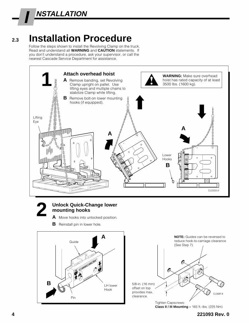
NSTALLATIONIFollow the steps shown to install the Revolving Clamp on the truck.Read and understand all WARNING and CAUTION statements. Ifyou don't understand a procedure, ask your supervisor, or call thenearest Cascade Service Department for assistance.
2 Unlock Quick-Change lowermounting hooksA Move hooks into unlocked position.
B Reinstall pin in lower hole.
1
Tighten Capscrews:Class II / III Mounting – 165 ft.-lbs. (225 Nm)
ca
sc
ad
e®
C-675514-1
CL0097.ill
A
Pin
LH lowerHook
NOTE: Guides can be reversed toreduce hook-to-carriage clearance(See Step 7).
5/8-in. (16 mm)offset on topprovides max.clearance.
Guide
WARNING: Make sure overheadhoist has rated capacity of at least3500 lbs. (1600 kg).
B
CL0333.ill
A
B
A
Attach overhead hoistA Remove banding, set Revolving
Clamp upright on pallet. Uselifting eyes and multiple chains tostabilize Clamp while lifting.
B Remove bolt-on lower mountinghooks (if equipped).
LiftingEye
LowerHooks
2.3 Installation Procedure

221093 Rev. 0 5
NSTALLATIONI
CL0334.ill
CLAMP
OPEN
Prepare HosesA Determine hose lengths required for hydrau-
lic supply configuration of truck.
B Cut hoses to length, install end fittings.
3
Flush hydraulic supply hosesA Install hoses as shown.
B Operate auxiliary valves for 30 sec.
C Remove union fittings, hoses.
D Connect hoses to Revolving Clampfittings as shown in Step 3 above.
4
RH & LH 2-PORT THINLINE™ HOSE REELS:
Open
Rotate CCW
Rotate CW
CAUTION: Use hoses that are workingpressure rated to 2600-psi (18,000 kPa)for all Attachment functions.
Clamp
5 Check oil level and removerubber vent cover
RC0139.ill
If necessary, fill gearbox with Cascade Gear Lube 656300 orequivalent SAE 90 wt. gear lube (AGMA 'mild' 6EP Gear Oil).
Oil level mustbe up tofill plug hole.
Remove rubbervent cover.
GA0081.ill
SOLENOID ADAPTION USING RH 6-N-1CABLE/HOSE REEL:
CL0489.ill
CLAMP
OPEN
Rotate CCW / Release(TANK Port)
Rotate CW / Clamp(PRESSURE Port)
Back (Driver"s) View
6 221093 Rev. 0
NSTALLATIONI
CL0336.ill
6
DIndex Block (ASME)
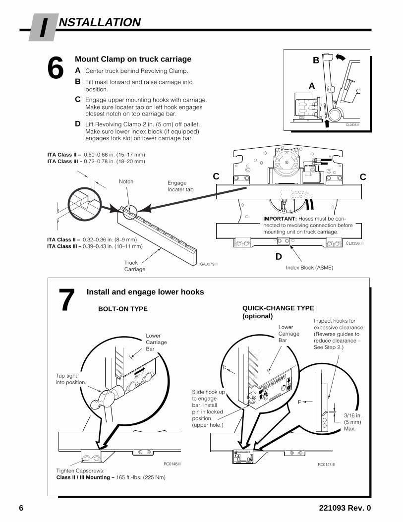
7 Install and engage lower hooks
GA0079.ill
C
BOLT-ON TYPE
RC0148.ill
ADJUST
Tap tightinto position.
Tighten Capscrews:Class II / III Mounting – 165 ft.-lbs. (225 Nm)
RC0147.ill
F
F
ca
sc
ad
e®
C-675514-1Slide hook upto engagebar, installpin in lockedposition.(upper hole.)
QUICK-CHANGE TYPE(optional)
LowerCarriageBar
Inspect hooks forexcessive clearance.(Reverse guides toreduce clearance –See Step 2.)
3/16 in.(5 mm)Max.
LowerCarriageBar
ITA Class II – 0.60–0.66 in. (15–17 mm)ITA Class III – 0.72–0.78 in. (18–20 mm)
ITA Class II – 0.32–0.36 in. (8–9 mm)ITA Class III – 0.39–0.43 in. (10–11 mm)
CL0335.ill
Notch
TruckCarriage
Engagelocater tab
C
A
B
IMPORTANT: Hoses must be con-nected to revolving connection beforemounting unit on truck carriage.
Mount Clamp on truck carriageA Center truck behind Revolving Clamp.
B Tilt mast forward and raise carriage intoposition.
C Engage upper mounting hooks with carriage.Make sure locater tab on left hook engagesclosest notch on top carriage bar.
D Lift Revolving Clamp 2 in. (5 cm) off pallet.Make sure lower index block (if equipped)engages fork slot on lower carriage bar.

221093 Rev. 0 7
NSTALLATIONI
RC0137.ill
8 Connect hoses prepared inStep 3 to hose terminals 9 Install stop block kit
• Preheat each stop block and carriagebar weld area to 325° F (180° C).
• Use AWS E7018 low hydrogen rodand weld a 1/4-in (6 mm) fillet aroundeach stop block.
Truck UpperCarriage Bar Back View
UpperMounting Hook
SteelStopBlock(eachside)
1/16 in.(1.5 mm)
CL0408.ill
11 Install wiring –(Solenoid-equipped units)
ROTATEPRESS BUTTON TO CLAMP
CL0974.ill
Buttontowarddriver
Truck controlvalve handle
Adapter
10 Install solenoid control knob –(solenoid-equipped units)
CL0258.ill CL0257.ill
Solenoid CoilUser-supplied wire
7.5-AmpFuse
White Black7.5-Amp FuseWhite Black
Solenoid Coil
Diode
Diode
KnobButton
Control Lever Knobwith Pushbutton
8 221093 Rev. 0
NSTALLATIONI
B D
CA
GA0005.ill
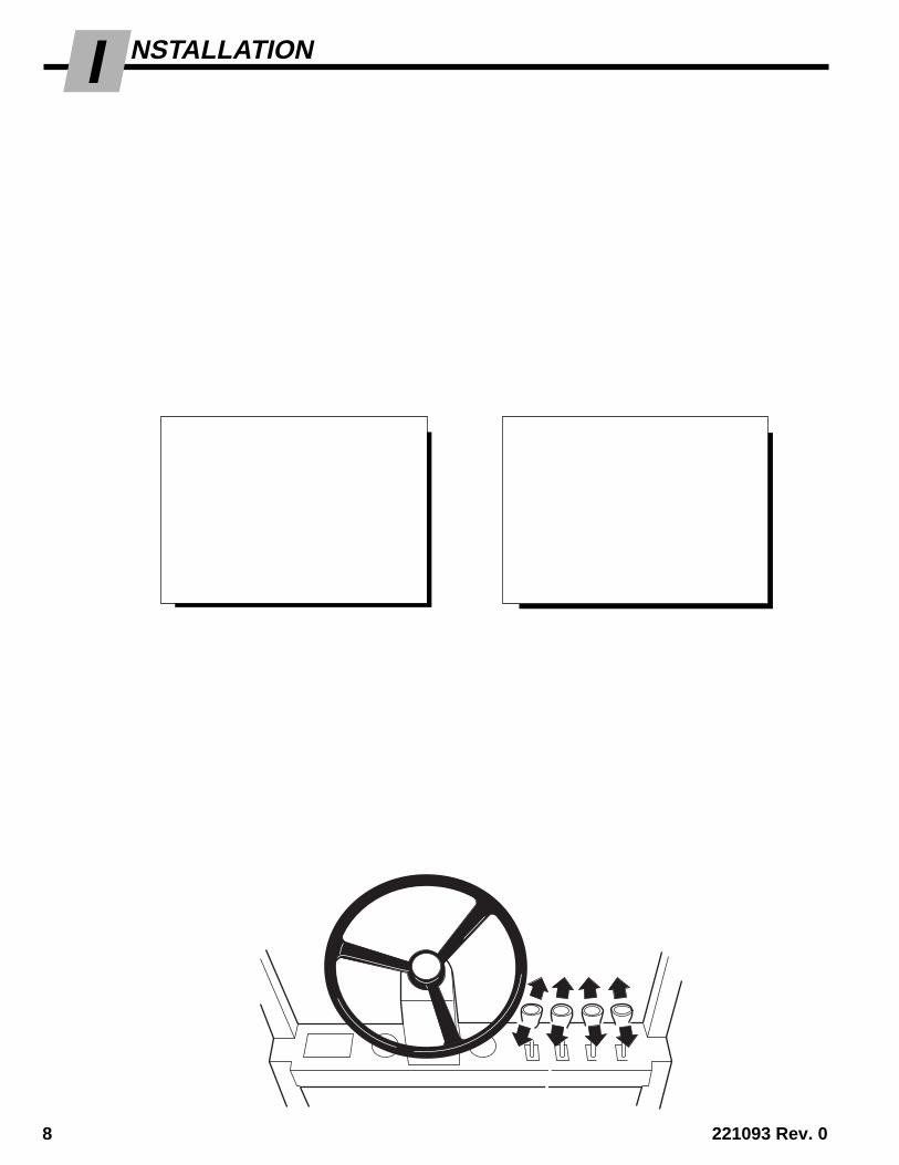
12 Check Revolving Clamp functions
• With no load, cycle CLAMP and ROTATEfunctions several times.
• Check functions for operation in accordancewith ITA (ISO) standards.
• Clamp and rotate a maximum load, checkfor equal arm movement and normal rotation.If necessary, adjust 180-degree stop valveand relief valve cartridges (see Step 13).
• Check for leaks at fittings, revolving connec-tion and cylinders.
AUXILIARY VALVE FUNCTIONSCheck for compliance withITA (ISO) standards:
REVOLVING CLAMP(Driver's view)
A Counterclockwise (CCW)
B Clockwise (CW)
C Release Arms
D Clamp Arms
Hoist DownTilt Forward
Hoist Up Tilt Back
WARNING: Make sure allpersonnel are clear of theClamp during testing.
CL0591.ill
SOLENOID-ACTIVATEDCLAMP
A Counterclockwise (CCW)
A Release Arms(press knob button)
B Clockwise (CW)
B Clamp Arms(press knob button)
CL0592.ill
B A
ABAB
C D CA
221093 Rev. 0 9
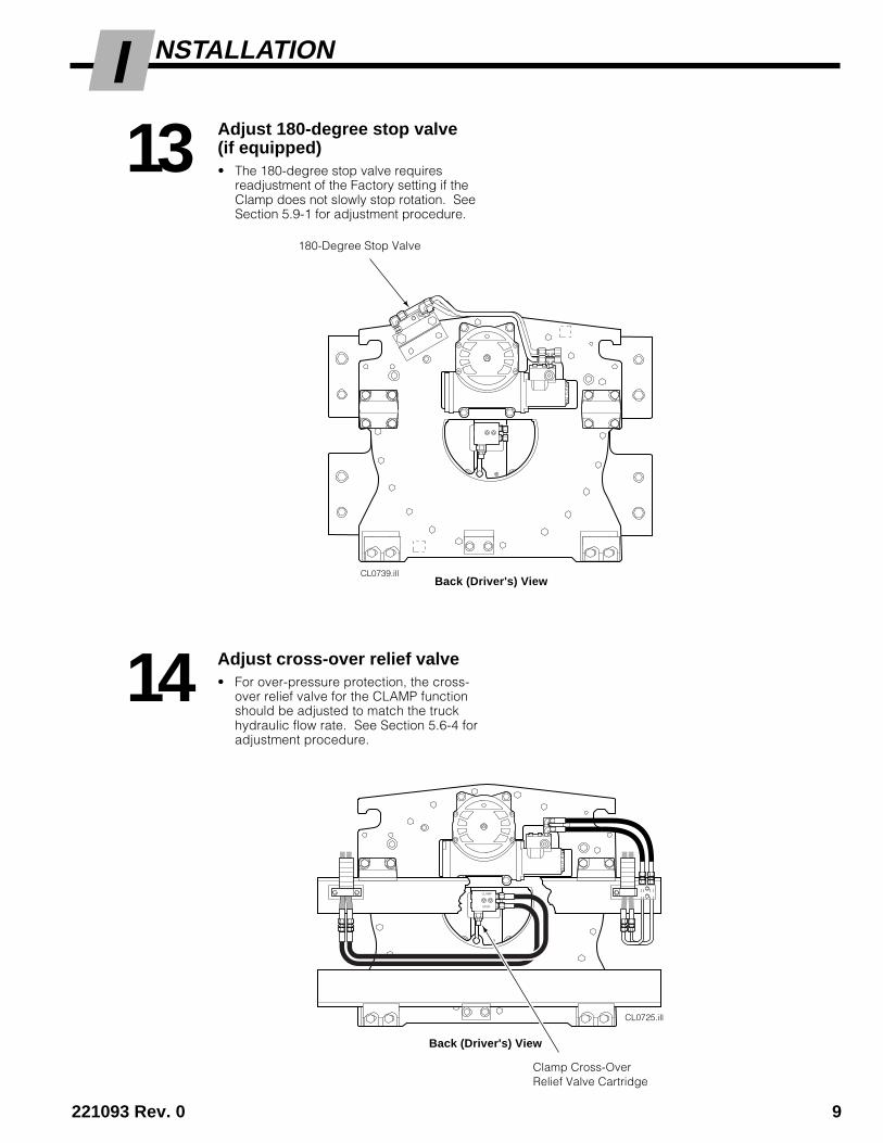
NSTALLATIONIAdjust 180-degree stop valve(if equipped)• The 180-degree stop valve requires
readjustment of the Factory setting if theClamp does not slowly stop rotation. SeeSection 5.9-1 for adjustment procedure.
13
14 Adjust cross-over relief valve• For over-pressure protection, the cross-
over relief valve for the CLAMP functionshould be adjusted to match the truckhydraulic flow rate. See Section 5.6-4 foradjustment procedure.
CL0725.ill
CLAMP
OPEN
Back (Driver's) View
Clamp Cross-OverRelief Valve Cartridge
CL0739.illBack (Driver's) View
180-Degree Stop Valve
10 221093 Rev. 0
ROUBLESHOOTINGT ERIODIC MAINTENANCEP
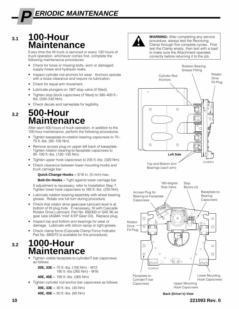
Access Plug forBearing-to-FaceplateCapscrews
CL0410.ill
CL0409.ill
RotatorDriveFill Plug
Rotation BearingGrease Fitting
Back (Driver's) View
Left Side
StopBlocks (2)
Top and Bottom ArmBearings (each arm)
180-degreeStop Valve
Cylinder RodAnchors
Lower MountingHook Capscrews
RotatorDriveFill Plug
Baseplate-to-BearingCapscrews
Faceplate-to-Cylinder/T-barCapscrews Upper Mounting
Hook Capscrews
WARNING: After completing any serviceprocedure, always test the RevolvingClamp through five complete cycles. Firsttest the Clamp empty, then test with a loadto make sure the Attachment operatescorrectly before returning it to the job.
3.1 100-HourMaintenanceEvery time the lift truck is serviced or every 100 hours oftruck operation, whichever comes first, complete thefollowing maintenance procedures:
• Check for loose or missing bolts, worn or damagedsupply hoses and hydraulic leaks.
• Inspect cylinder rod anchors for wear. Anchors operatewith a loose clearance and require no lubrication.
• Check for equal arm movement.
• Lubricate plungers on 180° stop valve (if fitted).
• Tighten stop block capscrews (if fitted) to 390–400 ft.-lbs. (530–540 Nm).
• Check decals and nameplate for legibility.
3.2 500-HourMaintenanceAfter each 500 hours of truck operation, in addition to the100-hour maintenance, perform the following procedures:
• Tighten baseplate-to-rotation bearing capscrews to 70–75 ft.-lbs. (95–105 Nm).
• Remove access plug on upper left back of baseplate.Tighten rotation bearing-to-faceplate capscrews to95–100 ft.-lbs. (130–135 Nm).
• Tighten upper hook capscrews to 235 ft.-lbs. (320 Nm).
• Check clearance between lower mounting hooks andtruck carriage bar:
Quick-Change Hooks – 3/16 in. (5 mm) max.
Bolt-On Hooks – Tight against lower carriage bar.
If adjustment is necessary, refer to Installation Step 7.Tighten lower hook capscrews to 165 ft.-lbs. (225 Nm).
• Lubricate rotation bearing assembly with wheel bearinggrease. Rotate one full turn during procedure.
• Check that rotator drive gearcase lubricant level is atbottom of fill plug hole. If necessary, fill with CascadeRotator Drive Lubricant, Part No. 656300 or SAE 90 wt.gear lube (AGMA 'mild' 6 EP Gear Oil). Replace plug.
• Inspect top and bottom arm bearings for wear ordamage. Lubricate with silicon spray or light grease.
• Check clamp force (Cascade Clamp Force IndicatorPart No. 680072 is available for this procedure).
3.2 1000-HourMaintenance• Tighten visible faceplate-to-cylinder/T-bar capscrews
as follows:
30E, 33E – 75 ft.-lbs. (100 Nm) – M12195 ft.-lbs (265 Nm) – M16
40E, 45E – 195 ft.-lbs. (265 Nm)
• Tighten cylinder rod anchor bar capscrews as follows:
30E, 33E – 30 ft.-lbs. (40 Nm)
40E, 45E – 50 ft.-lbs. (65 Nm)
221093 Rev. 0 11
ROUBLESHOOTINGT
Clamp Circuit• Clamp drops load after load is picked up.
• Clamp will not carry load to rated capacity.
• Clamp arms have uneven travel.
• Clamp arms travel slowly.
• Clamp arms will not move.
To correct these problems, see Sections 4.3-1and 4.3-2.
NOTE: Some Clamps have a regenerative hydrauliccircuit that opens the arms faster than when closing.This is a normal Clamp function.
Rotate Circuit• Clamp rotates in one direction only.
• Clamp will not rotate load to rated capacity.
• Clamp will not rotate.
To correct these problems, see Sections 4.4-1and 4.4-2.
• Clamp will not stop smoothly with 180° stop valve.
To correct this problem, see Section 5.9-1.
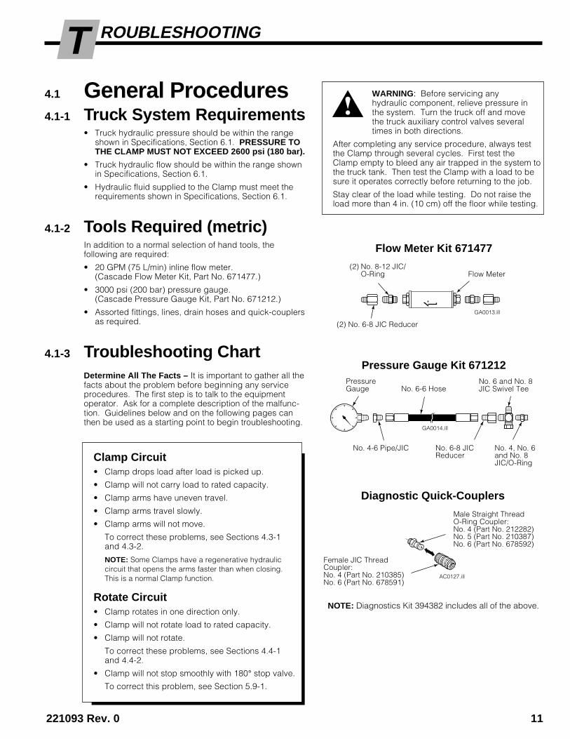
Pressure Gauge Kit 671212PressureGauge
No. 6 and No. 8JIC Swivel Tee
No. 4-6 Pipe/JIC
No. 6-6 Hose
Flow Meter Kit 671477
GA0013.ill
(2) No. 6-8 JIC Reducer
Flow Meter
No. 4, No. 6and No. 8JIC/O-Ring
No. 6-8 JICReducer
(2) No. 8-12 JIC/O-Ring
4.1 General Procedures4.1-1 Truck System Requirements
• Truck hydraulic pressure should be within the rangeshown in Specifications, Section 6.1. PRESSURE TOTHE CLAMP MUST NOT EXCEED 2600 psi (180 bar).
• Truck hydraulic flow should be within the range shownin Specifications, Section 6.1.
• Hydraulic fluid supplied to the Clamp must meet therequirements shown in Specifications, Section 6.1.
4.1-2 Tools Required (metric)In addition to a normal selection of hand tools, thefollowing are required:
• 20 GPM (75 L/min) inline flow meter.(Cascade Flow Meter Kit, Part No. 671477.)
• 3000 psi (200 bar) pressure gauge.(Cascade Pressure Gauge Kit, Part No. 671212.)
• Assorted fittings, lines, drain hoses and quick-couplersas required.
4.1-3 Troubleshooting ChartDetermine All The Facts – It is important to gather all thefacts about the problem before beginning any serviceprocedures. The first step is to talk to the equipmentoperator. Ask for a complete description of the malfunc-tion. Guidelines below and on the following pages canthen be used as a starting point to begin troubleshooting.
GA0014.ill
WARNING: Before servicing anyhydraulic component, relieve pressure inthe system. Turn the truck off and movethe truck auxiliary control valves severaltimes in both directions.
After completing any service procedure, always testthe Clamp through several cycles. First test theClamp empty to bleed any air trapped in the system tothe truck tank. Then test the Clamp with a load to besure it operates correctly before returning to the job.
Stay clear of the load while testing. Do not raise theload more than 4 in. (10 cm) off the floor while testing.
AC0127.ill
Diagnostic Quick-Couplers
Male Straight ThreadO-Ring Coupler:No. 4 (Part No. 212282)No. 5 (Part No. 210387)No. 6 (Part No. 678592)
Female JIC ThreadCoupler:No. 4 (Part No. 210385)No. 6 (Part No. 678591)
NOTE: Diagnostics Kit 394382 includes all of the above.
12 221093 Rev. 0
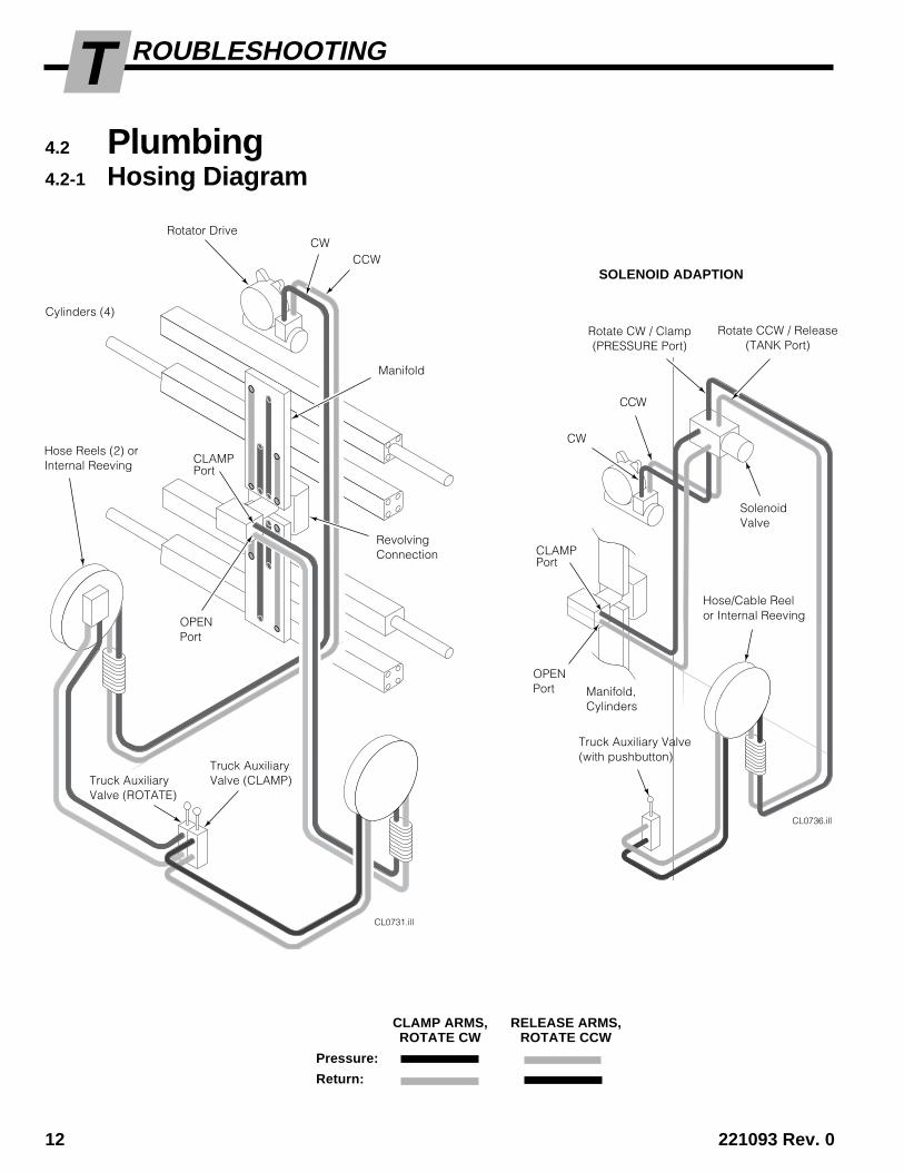
ROUBLESHOOTINGT4.2 Plumbing4.2-1 Hosing Diagram
CLAMP ARMS, RELEASE ARMS,ROTATE CW ROTATE CCW
Pressure:
Return:
CL0736.ill
SolenoidValve
SOLENOID ADAPTION
Rotate CW / Clamp(PRESSURE Port)
CL0731.ill
OPENPort
Cylinders (4)
CLAMPPort
CCWCW
Hose Reels (2) orInternal Reeving
RevolvingConnection
Rotator Drive
Truck AuxiliaryValve (ROTATE)
Truck AuxiliaryValve (CLAMP)
Truck Auxiliary Valve(with pushbutton)
Hose/Cable Reelor Internal Reeving
Manifold,Cylinders
OPENPort
CLAMPPort
Rotate CCW / Release(TANK Port)
CW
CCW
Manifold
221093 Rev. 0 13
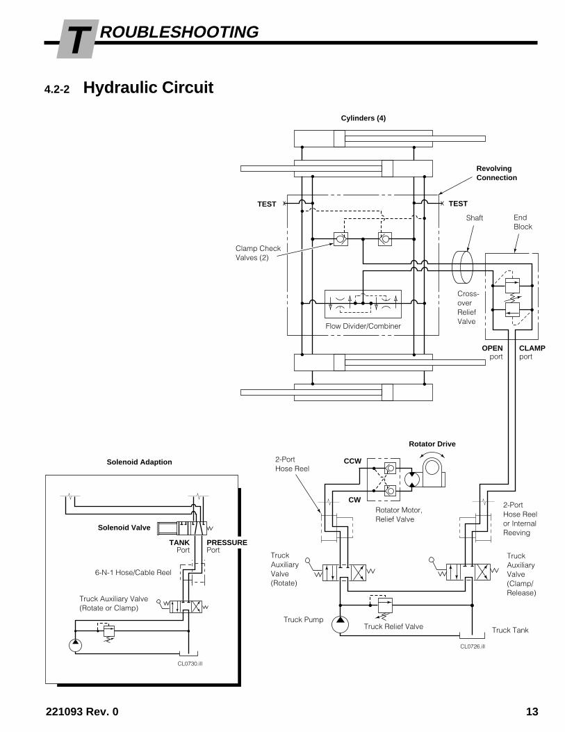
ROUBLESHOOTINGT4.2-2 Hydraulic Circuit
CL0730.ill
Solenoid Adaption
Truck Auxiliary Valve(Rotate or Clamp)
Solenoid Valve
6-N-1 Hose/Cable Reel
TANKPort
PRESSUREPort
CL0726.ill
RevolvingConnection
Shaft EndBlock
Cylinders (4)
Clamp CheckValves (2)
Flow Divider/Combiner
Cross-overReliefValve
TruckAuxiliaryValve(Clamp/Release)
Rotator Drive
Rotator Motor,Relief Valve
TruckAuxiliaryValve(Rotate)
CCW
CW
TEST
2-PortHose Reel
CLAMPport
OPENport
Truck PumpTruck Relief Valve Truck Tank
TEST
2-PortHose Reelor InternalReeving
14 221093 Rev. 0
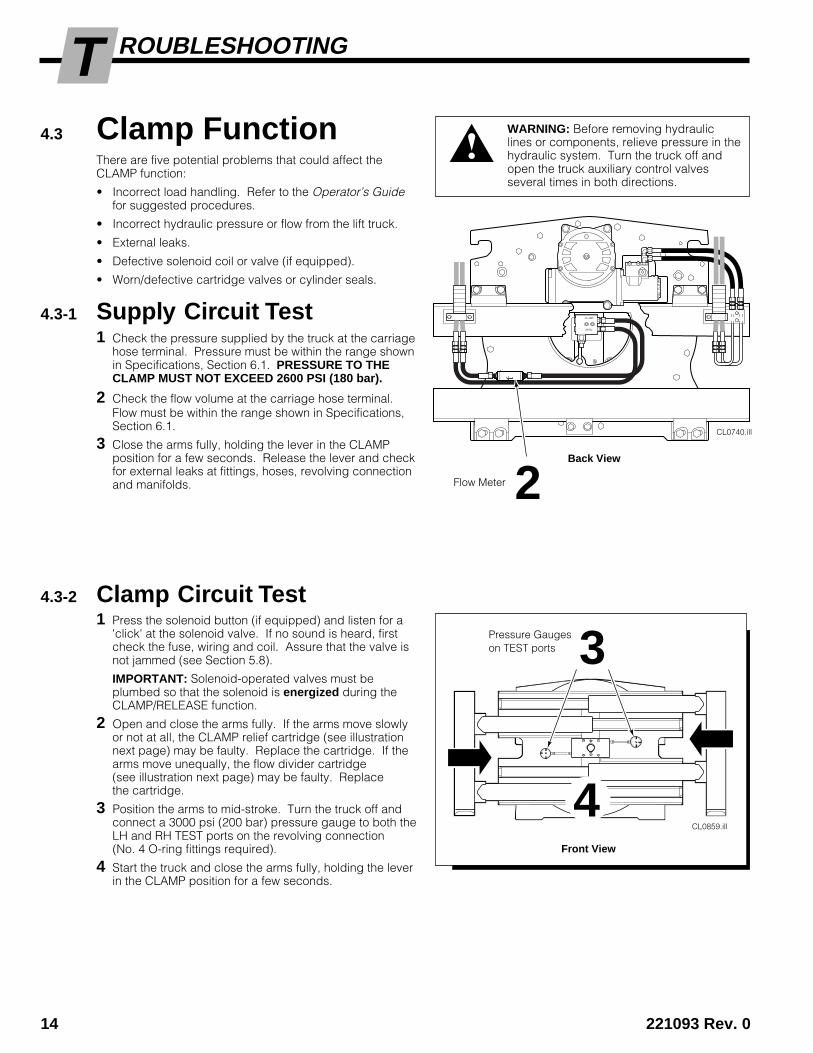
ROUBLESHOOTINGT4.3 Clamp Function
There are five potential problems that could affect theCLAMP function:
• Incorrect load handling. Refer to the Operator’s Guidefor suggested procedures.
• Incorrect hydraulic pressure or flow from the lift truck.
• External leaks.
• Defective solenoid coil or valve (if equipped).
• Worn/defective cartridge valves or cylinder seals.
4.3-1 Supply Circuit Test1 Check the pressure supplied by the truck at the carriage
hose terminal. Pressure must be within the range shownin Specifications, Section 6.1. PRESSURE TO THECLAMP MUST NOT EXCEED 2600 PSI (180 bar).
2 Check the flow volume at the carriage hose terminal.Flow must be within the range shown in Specifications,Section 6.1.
3 Close the arms fully, holding the lever in the CLAMPposition for a few seconds. Release the lever and checkfor external leaks at fittings, hoses, revolving connectionand manifolds.
4.3-2 Clamp Circuit Test1 Press the solenoid button (if equipped) and listen for a
'click' at the solenoid valve. If no sound is heard, firstcheck the fuse, wiring and coil. Assure that the valve isnot jammed (see Section 5.8).
IMPORTANT: Solenoid-operated valves must beplumbed so that the solenoid is energized during theCLAMP/RELEASE function.
2 Open and close the arms fully. If the arms move slowlyor not at all, the CLAMP relief cartridge (see illustrationnext page) may be faulty. Replace the cartridge. If thearms move unequally, the flow divider cartridge(see illustration next page) may be faulty. Replacethe cartridge.
3 Position the arms to mid-stroke. Turn the truck off andconnect a 3000 psi (200 bar) pressure gauge to both theLH and RH TEST ports on the revolving connection(No. 4 O-ring fittings required).
4 Start the truck and close the arms fully, holding the leverin the CLAMP position for a few seconds.
WARNING: Before removing hydrauliclines or components, relieve pressure in thehydraulic system. Turn the truck off andopen the truck auxiliary control valvesseveral times in both directions.
CL0740.ill
CLAMP
OPEN
Pressure Gaugeson TEST ports
Flow Meter
3
2Back View
Front View
CL0859.ill
4

221093 Rev. 0 15
ROUBLESHOOTINGT
TESTCL0856.ill
4.4 Rotation FunctionThere are six potential problems that could affect theROTATE function:
• Incorrect load handling. Refer to the Operator’s Guidefor suggested procedures.
• Incorrect hydraulic pressure or flow from the lift truck.
• External leaks.
• Defective solenoid coil or valve (if equipped).
• Worn/defective hydraulic rotator motor.
• Worn/defective drive box or rotation bearing assembly.
4.4-1 Supply Circuit Test1 Check the pressure supplied by the truck at the carriage
hose terminal. Pressure must be within the range shownin Specifications, Section 6.1. PRESSURE TO THECLAMP MUST NOT EXCEED 2600 PSI (180 bar).
2 Check the flow volume at the carriage hose terminal.Flow must be within the range shown in Specifications,Section 6.1.
3 Rotate clockwise (CW) or counterclockwise (CCW) to thestops, holding the lever in the ROTATE position for a fewseconds. Release the lever and check for external leaksat fittings, hoses, revolving connection and manifolds.
WARNING: Before removing hydrauliclines or components, relieve pressure inthe hydraulic system. Turn the truck offand open the truck auxiliary control valvesseveral times in both directions.
Flow Meter 2
Back View
REVOLVING CONNECTION
CLAMPCheck (2)
FlowDivider
5
5 Release the lever and watch the pressure gauge:
• If the pressure drop is less than 150 psi (10 bar)initially, and additional drop does not exceed 25 psi(1.7 bar) per minute, the problem is not hydraulic(see Section 4.1-3).
• If the pressure drop is more than 150 psi (10 bar)initially, and additional drop exceeds 25 psi (1.7bar) per minute, the CLAMP check valve cartridgesmay be faulty. Replace the cartridges.
CLAMPCheck (2)
6 Close the arms fully and hold the lever in the CLAMPposition for a few seconds. If the pressure still drops asbefore, the cylinders are faulty and must be serviced(see Section 5.6).
CL0791.ill
5
2CLAMP Cross-overRelief Cartridge(Accessible from back)
2Front View
Body
End Block
Shaft
Pressure gaugeon LH TEST Port
Pressure gaugeon RH TEST Port
16 221093 Rev. 0
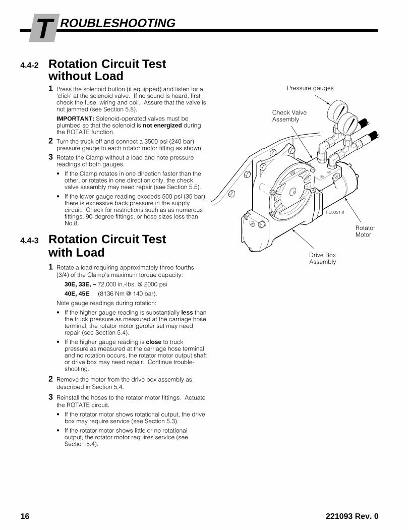
ROUBLESHOOTINGT4.4-2 Rotation Circuit Test
without Load1 Press the solenoid button (if equipped) and listen for a
'click' at the solenoid valve. If no sound is heard, firstcheck the fuse, wiring and coil. Assure that the valve isnot jammed (see Section 5.8).
IMPORTANT: Solenoid-operated valves must beplumbed so that the solenoid is not energized duringthe ROTATE function.
2 Turn the truck off and connect a 3500 psi (240 bar)pressure gauge to each rotator motor fitting as shown.
3 Rotate the Clamp without a load and note pressurereadings of both gauges.
• If the Clamp rotates in one direction faster than theother, or rotates in one direction only, the checkvalve assembly may need repair (see Section 5.5).
• If the lower gauge reading exceeds 500 psi (35 bar),there is excessive back pressure in the supplycircuit. Check for restrictions such as as numerousfittings, 90-degree fittings, or hose sizes less thanNo.8.
4.4-3 Rotation Circuit Testwith Load1 Rotate a load requiring approximately three-fourths
(3/4) of the Clamp's maximum torque capacity:
30E, 33E, – 72,000 in.-lbs. @ 2000 psi
40E, 45E (8136 Nm @ 140 bar).
Note gauge readings during rotation:
• If the higher gauge reading is substantially less thanthe truck pressure as measured at the carriage hoseterminal, the rotator motor geroler set may needrepair (see Section 5.4).
• If the higher gauge reading is close to truckpressure as measured at the carriage hose terminaland no rotation occurs, the rotator motor output shaftor drive box may need repair. Continue trouble-shooting.
2 Remove the motor from the drive box assembly asdescribed in Section 5.4.
3 Reinstall the hoses to the rotator motor fittings. Actuatethe ROTATE circuit.
• If the rotator motor shows rotational output, the drivebox may require service (see Section 5.3).
• If the rotator motor shows little or no rotationaloutput, the rotator motor requires service (seeSection 5.4).
RC0351.ill
Pressure gauges
Check ValveAssembly
Drive BoxAssembly
RotatorMotor

221093 Rev. 0 17
ROUBLESHOOTINGT4.5 Electrical Circuit
(Solenoid-equipped Clamps)Use the electrical schematic and diagram shown andfollow the steps below:
1 Check the control knob circuit fuse. Replace ifnecessary.
2 Check for loose electrical connections at the truckignition switch, control knob button, solenoid coilterminals and diode.
3 Remove the diode from the solenoid coil terminal. Testwith an ohmmeter for high resistance in one directionand no resistance in the other direction. If there is noresistance in both directions, replace the diode.
NOTE: When replacing the diode, the banded (+) endmust be connected to the coil and wiring as shown.
4 Disconnect the electrical leads from the solenoid coilterminals. Use a voltmeter to determine if voltage ispresent at the electrical leads when the button isdepressed.
• If there is no current to the solenoid, troubleshootthe electrical circuit for shorts.
• If there is current to the solenoid, test for coilcontinuity.
5 Test for coil continuity by placing an ohmmeter testlead on each solenoid coil terminal (ohmmeter on Rx1scale).
• If there is an ohmmeter reading, the coil is good.
• If the coil is good, but the solenoid does not 'click'when the control knob button is depressed, thesolenoid cartridge may be jammed. Refer toSection 5.6.
• If there is no ohmmeter reading, the coil is defectiveand should be replaced. Refer to Section 5.6.
Solenoid Coil
CL0258.ill CL0257.ill
Solenoid CoilUser-supplied wire
7.5-AmpFuse
White Black7.5-Amp FuseWhite Black
Solenoid Coil
Diode
Diode
KnobButton
Control Lever Knobwith Pushbutton
18 221093 Rev. 1
ERVICES
CL0684.ill
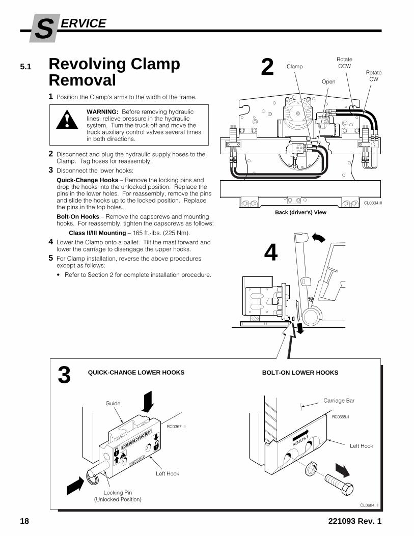
5.1 Revolving ClampRemoval1 Position the Clamp's arms to the width of the frame.
2 Disconnect and plug the hydraulic supply hoses to theClamp. Tag hoses for reassembly.
3 Disconnect the lower hooks:
Quick-Change Hooks – Remove the locking pins anddrop the hooks into the unlocked position. Replace thepins in the lower holes. For reassembly, remove the pinsand slide the hooks up to the locked position. Replacethe pins in the top holes.
Bolt-On Hooks – Remove the capscrews and mountinghooks. For reassembly, tighten the capscrews as follows:
Class II/III Mounting – 165 ft.-lbs. (225 Nm).
4 Lower the Clamp onto a pallet. Tilt the mast forward andlower the carriage to disengage the upper hooks.
5 For Clamp installation, reverse the above proceduresexcept as follows:
• Refer to Section 2 for complete installation procedure.
WARNING: Before removing hydrauliclines, relieve pressure in the hydraulicsystem. Turn the truck off and move thetruck auxiliary control valves several timesin both directions.
CL0334.ill
CLAMP
OPEN
ca
sc
ad
e®
C-675514-1
RC0367.ill
RC0368.ill
ADJUST
ClampRotateCCW
Open
RotateCW
Back (driver's) View
2
4
3 QUICK-CHANGE LOWER HOOKS BOLT-ON LOWER HOOKS
Guide
Left Hook
Locking Pin(Unlocked Position)
Carriage Bar
Left Hook

221093 Rev. 1 19
ERVICES5.2 Arms5.2-1 Arm Assemblies –
Removal and InstallationThe following procedures can be performed with theRevolving Clamp mounted on the truck.
1 Position the arms to frame width. Lower the Clamp toposition the arms 1/2 in. (13 mm) above the floor.
2 Remove the upper and lower cylinder rod anchor bars onthe arm to be removed. Slowly power the cylinder rodsopen to expose the rod end. For reassembly, applyLoctite 242 (Blue) and tighten the anchor bar capscrewsto the following torque value:
20E, 30E, 33E – 50 ft.-lbs. (65 Nm).
40E, 45E – 80 ft.-lbs. (105 Nm).
3 Slide the rod end toward the cylinder to removethe split-ring keepers. Slide the rod end off the cylinderrod. Inspect rod end and keepers for wear.
4 Retract the cylinder rods fully.
5 Attach an overhead hoist and chain to the arm assembly.Position the chain clear of the arm bearing surfaces.CAUTION: Use a second chain and lift eyebolt on thecontact pad to stabilize the arms.
6 Slide the arm assembly out of the frame. Do not damagethe bearings when removing the arm.
7 For reassembly, reverse the above procedures with thefollowing exceptions:
• Inspect the upper and lower bearing strips for wear.Bearing thickness should not be less than 1/8 in. (3mm) as measured on the bottom or sides of the strip.Install new bearings as required.
• Inspect the arm bar bearing contact surface andchamfered areas for nicks or damage. Break anysharp edges and polish with 400-grit emery paper asnecessary.
• Lubricate with silicone spray or light grease.
WARNING: Make sure the hoist used toremove the arm has a rated capacity of atleast 1000 lbs. (450 kg.)
CL0374.ill
CL0783.ill
Cylinder RodAnchor Bar
Rod End
Split-RingKeepers 1/2-in. (13 mm)
Above Floor
CL0782.ill
1/2-in. (13 mm)Above Floor
REVOLVINGBALE CLAMP
REVOLVINGFORK CLAMP
2
7
3
4
5

20 221093 Rev. 1
ERVICES5.2-2 Drum Arm Contact Pad –
Surface ReplacementThe following procedures can be performed with theRevolving Clamp mounted on the truck.
Single Drum Arms .
1 Drill out the rivets using a 3/16-in (5 mm) drill bit. Drillfrom the back side of the arm. Align the new contactsurface to the arm. Drill through using the 3/16 (5 mm)drill bit. Rivet the contact surface to the arm.
Multiple Drum Arms
2 Remove the snap ring, pivot pin, thrust washers andcontact pads to provide access to the rivets. Replacethe contact surfaces as in Step 1. Reinstall the contactpads.
CL0429.ill
CL0370.ill
1
2
Contact Surface
Rivet (6)
PivotingContactPad
221093 Rev. 1 21
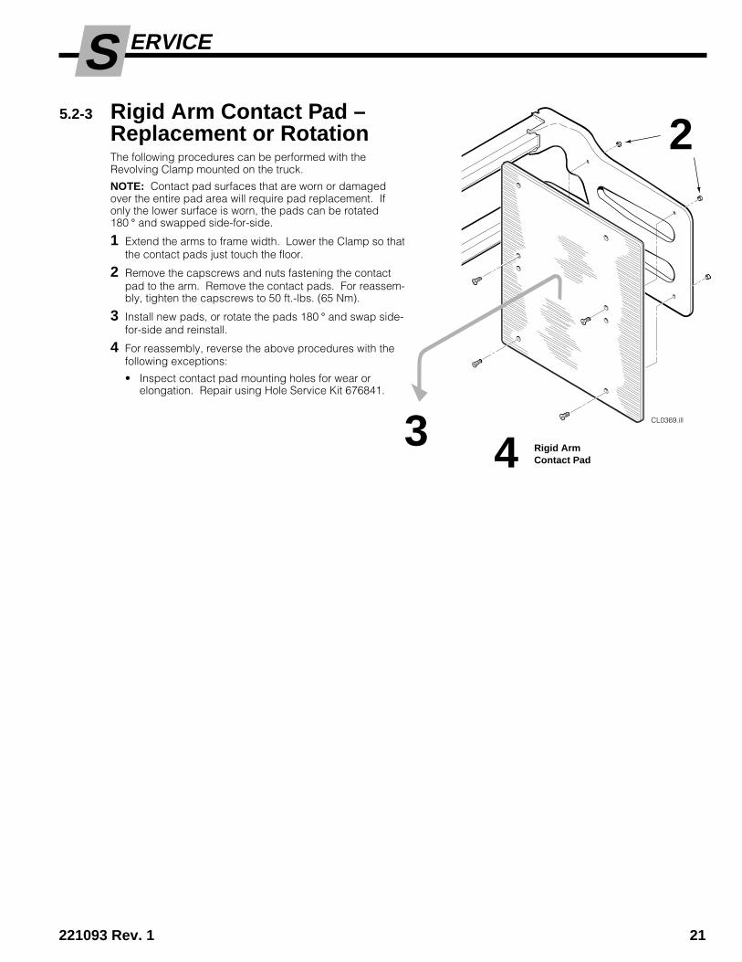
ERVICES5.2-3 Rigid Arm Contact Pad –
Replacement or RotationThe following procedures can be performed with theRevolving Clamp mounted on the truck.
NOTE: Contact pad surfaces that are worn or damagedover the entire pad area will require pad replacement. Ifonly the lower surface is worn, the pads can be rotated180 ° and swapped side-for-side.
1 Extend the arms to frame width. Lower the Clamp so thatthe contact pads just touch the floor.
2 Remove the capscrews and nuts fastening the contactpad to the arm. Remove the contact pads. For reassem-bly, tighten the capscrews to 50 ft.-lbs. (65 Nm).
3 Install new pads, or rotate the pads 180 ° and swap side-for-side and reinstall.
4 For reassembly, reverse the above procedures with thefollowing exceptions:
• Inspect contact pad mounting holes for wear orelongation. Repair using Hole Service Kit 676841.
CL0369.ill
2
3 Rigid ArmContact Pad4
22 221093 Rev. 1
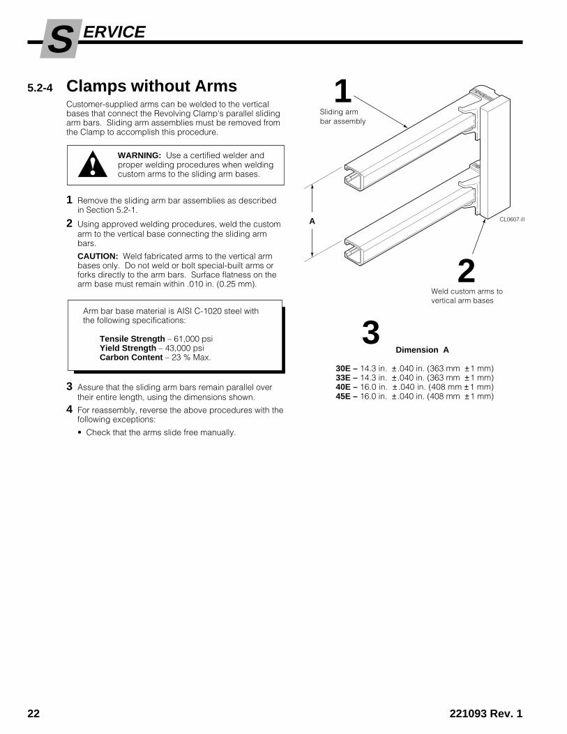
ERVICES5.2-4 Clamps without Arms
Customer-supplied arms can be welded to the verticalbases that connect the Revolving Clamp's parallel slidingarm bars. Sliding arm assemblies must be removed fromthe Clamp to accomplish this procedure.
1 Remove the sliding arm bar assemblies as describedin Section 5.2-1.
2 Using approved welding procedures, weld the customarm to the vertical base connecting the sliding armbars.
CAUTION: Weld fabricated arms to the vertical armbases only. Do not weld or bolt special-built arms orforks directly to the arm bars. Surface flatness on thearm base must remain within .010 in. (0.25 mm).
3 Assure that the sliding arm bars remain parallel overtheir entire length, using the dimensions shown.
4 For reassembly, reverse the above procedures with thefollowing exceptions:
• Check that the arms slide free manually.
Arm bar base material is AISI C-1020 steel withthe following specifications:
Tensile Strength – 61,000 psiYield Strength – 43,000 psiCarbon Content – 23 % Max.
WARNING: Use a certified welder andproper welding procedures when weldingcustom arms to the sliding arm bases.
Dimension A
30E – 14.3 in. ± .040 in. (363 mm ±1 mm)33E – 14.3 in. ± .040 in. (363 mm ±1 mm)40E – 16.0 in. ± .040 in. (408 mm ±1 mm)45E – 16.0 in. ± .040 in. (408 mm ±1 mm)
CL0607.illA
3
Weld custom arms tovertical arm bases
Sliding armbar assembly
2
1

221093 Rev. 1 23
ERVICES
CL0729.ill
BottomBearing
CL0688.ill
Right Side
UpperArms
LowerArms
TopBearing
3
4
5
2
10
5.2-5 Arm Bearings –Removal and InstallationThe following procedure can be performed with the armsin place and the Revolving Clamp mounted on the truck.
NOTE: Normally only the long bearing segments need tobe replaced due to wear. If inspection reveals wear onthe short bearing segments, replace them also.
IMPORTANT: Remove and replace the bearings from therod end of each cylinder. Start at the uppermost armbearing as shown and work down, replacing one bearingat a time to keep the Clamp arms fully supported.
1 Raise the Clamp off the floor and close the arms.
2 Remove the arm bearing retainer.
3 Slowly open the arms to drag the top bearing out ofthe bearing way.
4 If the bearings are tight, close the arms and attachclamp-type pliers to the end of the bearing. Slowlyopen the arms to drag the bearing out.
5 Close the arms. Using a 1/8 to 3/16-in. (3 to 5 mm)thick piece of rod or flat stock, drive the shorterbearing segment out of the bearing way as the armsare slowly opened.
6 Open the arms to the mid-way position.
WARNING: Make sure that a safety personis at the truck controls at all times if thismaintenance procedure is done with thetruck running.
7 Install new bearing segments. Slowly close the arms todrag the bearing segments into the bearing way.
8 Remove and replace the bottom bearing set on thesame arm.
9 Install the arm bearing retainer. Apply Loctite 242(Blue) to the capscrew threads and tighten the cap-screw to 15 ft.-lbs. (20 Nm).
10 Replace the remaining arm bearings by following thesame procedure as in Steps 2 through 9.
Lubricate the bearings with silicone spray or lightgrease. Cycle the arms and check for freedom ofmovement.

24 221093 Rev. 0
S ERVICE
5.3 Drive Group5.3-1 Drive Group –
Removal and Installation1 Remove the Revolving Clamp from the truck as
described in Section 5.1.
2 Remove the four capscrews fastening the drive groupto the baseplate. For reassembly, tighten the cap-screws to 65–75 ft.-lbs. (90–100 Nm).
3 For reassembly, reverse the above procedures withthe following exceptions:
• After the drive group has been reinstalled, checkthe gearcase lubricant level. Lubricant must be upto the bottom of the fill plug hole. If necessary, fillwith Cascade Gear Lube Part No. 656300, or SAE90 wt. gear lube (AGMA 'mild' 6 EP Gear Lube).
5.3-2 Drive Group –Disassembly and Service1 Remove the drive group from the baseplate as
described in Section 5.3-1.
2 Lay the drive group, pinion down, on two 4 x 4 woodblocks placed on both sides of the pinion.
3 Remove the four capscrews fastening the cover plateto the housing.
4 Remove the center capscrew plug from the coverplate and install a 3/8-in. NC capscrew with a mini-mum of 2 in. (5 cm) thread length. Remove the coverplate by turning the capscrew clockwise while lightlytapping around the sides of the cover plate.
5 Drain the lubricant from the housing.
6 Remove the three capscrews fastening the end coverto the housing.
7 Remove the drive motor as described in Section 5.4-1.
RC0171.ill
RC0172.ill
23
4 37
5
2 6
CoverPlate
Housing
Drive Group
221093 Rev. 0 25
S ERVICE
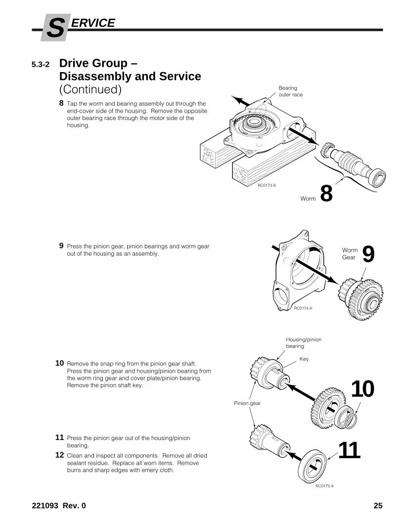
5.3-2 Drive Group –Disassembly and Service(Continued)8 Tap the worm and bearing assembly out through the
end-cover side of the housing. Remove the oppositeouter bearing race through the motor side of thehousing.
9 Press the pinion gear, pinion bearings and worm gearout of the housing as an assembly.
10 Remove the snap ring from the pinion gear shaft.Press the pinion gear and housing/pinion bearing fromthe worm ring gear and cover plate/pinion bearing.Remove the pinion shaft key.
11 Press the pinion gear out of the housing/pinionbearing.
12 Clean and inspect all components. Remove all driedsealant residue. Replace all worn items. Removeburrs and sharp edges with emery cloth.
RC0173.ill
RC0174.ill
RC0175.ill
8
9
10
11
Bearingouter race
Key
Housing/pinionbearing
Pinion gear
Worm
WormGear

26 221093 Rev. 0
S ERVICE
5.3-3 Drive Group Reassembly1 Apply Loctite sealant 515 (Cascade Part No. 668184)
to the pinion shaft seating area and shoulder for thehousing/pinion bearing. Install the housing/pinionbearing. Remove excess sealant.
2 Install the key, worm gear, cover plate/pinion bearingand snap ring on the pinion.
3 Apply Loctite sealant 515 (Cascade Part No. 668184)to the housing seating area and shoulder for thehousing/pinion bearing. Install the pinion assembly inthe housing. Remove excess sealant.
4 Install the worm outer bearing race in the drive motorside of the housing. Make sure the race taper isinward.
5 Install the drive motor as described in Section 5.4-1.
6 Install the worm and bearings in the housing. Fullyengage the worm with the drive motor shaft. Install theremaining outer bearing race. Make sure the taper isinward.
�����������������������������������
RC0176.ill
RC0177.ill
������������������������������
RC0178.ill
��������������� ����������
��
�� RC0179.ill
6
4
5
1
2
Piniongear
Key
3Housing
221093 Rev. 0 27
S ERVICE
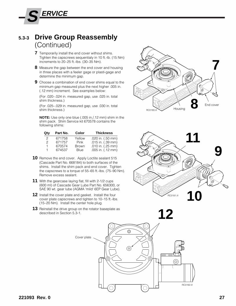
5.3-3 Drive Group Reassembly(Continued)7 Temporarily install the end cover without shims.
Tighten the capscrews sequentialy in 10 ft.-lb. (15 Nm)increments to 20–25 ft.-lbs. (30–35 Nm).
8 Measure the gap between the end cover and housingin three places with a feeler gage or plasti-gage anddetermine the minimum gap.
9 Choose a combination of end cover shims equal to theminimum gap measured plus the next higher .005 in.(.12 mm) increment. See examples below:
(For .020–.024 in. measured gap, use .025 in. totalshim thickness.)
(For .025–.029 in. measured gap, use .030 in. totalshim thickness.)
NOTE: Use only one blue (.005 in./.12 mm) shim in theshim pack. Shim Service kit 670578 contains thefollowing shims:
Qty Part No. Color Thickness
2 671758 Yellow .020 in. (.50 mm)2 671757 Pink .015 in. (.39 mm)1 670574 Brown .010 in. (.25 mm)1 674537 Blue .005 in. (.12 mm)
10 Remove the end cover. Apply Loctite sealant 515(Cascade Part No. 668184) to both surfaces of theshims. Install the shim pack and end cover. Tightenthe capscrews to a torque of 55–65 ft.-lbs. (75–90 Nm).Remove excess sealant.
11 With the gearcase laying flat, fill with 2-1/2 cups(600 ml) of Cascade Gear Lube Part No. 656300, orSAE 90 wt. gear lube (AGMA 'mild' 6EP Gear Lube).
12 Install the cover plate and gasket. Install the fourcover plate capscrews and tighten to 10–15 ft.-lbs.(15–20 Nm). Install the center hole plug.
13 Reinstall the drive group on the rotator baseplate asdescribed in Section 5.3-1.
RC0180.ill
RC0181.ill
RC0182.ill
12Cover plate
11
10
9
7
8HousingEnd cover

28 221093 Rev. 0
S ERVICE
5.4 Drive Motor5.4-1 Drive Motor –
Removal and Installation1 Remove the Revolving Clamp from the lift truck as
described in Section 5.1.
2 Remove the drive group from the Clamp as describedin Section 5.3-1.
3 Remove the fill plug and drain the lubricant from thedrive group.
4 Lay the drive group, pinion down, on two 4 x 4 (10 x10 cm) wood blocks placed on both sides of thepinion gear.
5 Remove the four capscrews fastening the check valveassembly to the drive motor. Keep track of the twoO-rings between the check valve assembly and drivemotor. For reassembly, tighten the capscrews to20 ft.-lbs. (25 Nm).
6 Remove the three capscrews fastening the adapterplate to the gearcase housing. Tap on the drive motorwith a rubber mallet to separate the drive motor/adapter plate assembly from the gearcase housing.
7 Remove the four capscrews fastening the adapterplate to the drive motor and separate the motor fromthe adapter plate.
8 For reassembly, reverse the above procedures exceptas follows:
• Apply Loctite sealant 515 (Cascade Part No.668184) to both sides of the drive motor/adapterplate gasket. Apply sealant to the threads of thefour drive motor capscrews. Install the gasket andadapter plate to the drive motor. Tightencapscrews to 30–40 ft.-lbs. (50–55 Nm).
• Apply sealant to both sides of the adapter plate/gearcase housing gasket. Apply sealant to thethreads of the three adapter plate capscrews.Install the drive motor/adapter plate assembly andgasket to the gearcase housing. Tighten thecapscrews to 55–65 ft.-lbs. (75–90 Nm).
• Fill the drive group with 2-1/2 cups (600 ml)Cascade Gear Lube Part No. 656300, or SAE 90wt.gear lube (AGMA 'mild' 6 EP Gear Lube).
WARNING: Before removing hydrauliclines or components, relieve pressure in theAttachment hydraulic system. Turn thetruck off and move the auxiliary controlvalves several times in both directions.
RC0183.ill
5 6
8
4 3
87
Drive Motor
O-rings
AdapterPlate

221093 Rev. 0 29
S ERVICE
5.4-2 Drive Motor DisassemblyCascade provides service replacement parts for theunshaded parts only. Due to cost, if other parts needreplacement, the complete drive motor assembly shouldbe replaced.
1 Remove the drive motor from the drive group asdescribed in Section 5.4-1.
IMPORTANT: Clean the outside of the drive motorand service in a clean, dust-free work area. Use asoft-jawed vise for all service procedures.
2 Drain the hydraulic fluid from the drive motor byrotating the shaft. Plug the ports.
3 Clamp the drive motor in a vise across the flange withthe shaft downward.
4 Remove the capscrews/seal washers, end cap/seal,Geroler set/seal, spacer plate/seal, splined drive,shaft, needle thrust bearing and bearing race.
5 Turn the drive motor over, clamping the housingacross the port area with the flange upward.
6 Remove the four capscrews from the flange. Do notuse an impact wrench (see CAUTION below).
CAUTION: Thread-locker used on the capscrewsmay require that a small amount of heat be applied tothe housing (400° F / 200° C), to remove thecapscrews. Use a temperature indicator to preventoverheating the housing.
7 Remove the flange from the housing.
8 Remove the exclusion seal and pressure seal from theflange using a seal removal tool or modified screw-driver as shown.
CAUTION: Do not scratch either of the seal cavities.
9 Using an Allen wrench, remove the metal plug andseal from the housing.
RC0184.ill
3
RR0092.ill
7 9
6
4
RC0186.ill
5
RC0188.ill
9 Allen wrench
RC0187.ill
Pressure Seal
ExclusionSeal
O-ring
Housing
Flange
BearingRace
ThrustBearing
Shaft
SplinedDrive
SpacerPlate
Gerotor Set
EndCap
Sealwashers
Capscrews (7)
Capscrews (4)
8

30 221093 Rev. 0
S ERVICE
5.4-3 Drive Motor Inspection• Remove all Loctite residue from the threaded holes.
• Clean all parts with solvent and blow dry. Do not usepaper or cloth towels.
• Inspect all parts for small nicks or burrs. Remove anysmall nicks or burrs with emery cloth. Replace partswith scratches or burrs that could cause leakage.
• Inspect the flange seal seats for scratches. Check forcracks in the flange area that could cause leakage.
5.4-4 Drive Motor Reassembly1 Clamp the housing with the flange side upward.
2 Install the plug and seal into housing if it was re-moved. Push plug into housing until flush withhousing surface. Do not damage the seal.
3 Install the flange without the exclusion seal andpressure seal. Use two capscrews only.
4 Turn the housing over and clamp across the flange.
5 Lubricate the needle thrust bearing, bearing race andshaft with hydraulic fluid. Install the needle thrustbearing and bearing race on the shaft. Install theshaft into the housing. The bearing race must rotatefreely in position.
IMPORTANT: Do not allow hydraulic fluid to get intothe housing threaded holes.
6 Install the splined drive into the shaft with the longersplined end (if applicable) down.
7 Install the seal and spacer plate to the housing.
IMPORTANT: Line up the timing mark on the shaftwith a threaded capscrew hole. Mark the hole. Makesure the slots in the spacer plate provide passage forhydraulic fluid. If the spacer plate is flipped, the motorwill not operate.
RC0189.ill
RR0093.ill
RC0209.ill
RC0210.ill
21
3
5
4
76
Timing Mark
Flange
ExclusionSeal
Plug
Capscrews (4)
PressureSeal
O-ringHousing
BearingRace
ThrustBearing
Shaft
SplinedDrive
SpacerPlate
GerotorSet
SealWashers
Capscrews (7)
EndCap

221093 Rev. 0 31
S ERVICE
8 Install the seal and Gerotor set on the spacer plate.IMPORTANT: Make sure a lobe point on the gerolerset matches up with the reference threaded capscrewhole marked in Step 7.
9 Install the seal and end cap, seal washers andcapscrews. Pre-tighten the capscrews to a torque of15–40 in.-lbs. (2–5 Nm). Make sure the housing andgeroler seals are properly seated. Final-tighten thecapscrews using a criss-cross tightening pattern to200 in.-lbs. (22 Nm).
10 Turn the housing over and clamp across the port areawith the shaft upward.
11 Remove the flange from the housing.
12 Lubricate the exclusion seal with petroleum jelly andpress into the flange.
13 Place the pressure seal on the shaft, flush against thebearing race. Lubricate the outer surface of the sealwith petroleum jelly.
14 Place the flange on the shaft flush against the pressureseal. Install the four capscrews and tighten eachcapscrew one rotation at a time. The pressure sealmust enter the flange seat evenly. Alternately tightenuntil the flange is tight against the housing.
15 Remove the flange from the housing and inspect thepressure seal for proper seating into the flange.
16 Clean the four capscrews and their correspondingthreaded holes in the housing. Use a non-petroleumbased solvent and blow dry. Apply Loctite Primer 'NF'to the holes and allow to dry 1 minute minimum.
17 Apply 4 drops of Loctite 601 sealant to the threads ofeach of the four housing holes. Wipe away any excesssealant. Do not let the sealant dry more than 15minutes before installing the capscrews.
18 Apply a liberal amount of petroleum jelly to theexclusion seal, pressure seal and shaft.
19 Install the flange seal into the flange, and install theflange to the housing. Install the four capscrews andtighten in a criss-cross pattern to 250 in.-lbs. (28 Nm).
IMPORTANT: The capscrews must be clean and dry.
RR0094.ill
RC0212.ill
8
9
1110
13
Lobe Point
Seal
14
Housing
Pressure seal
Flange
������������
RC0213.ill
12 Exclusionseal
5.4-4 Drive Motor Reassembly (Continued)
Sealwashers (7)
End Cap
Bearing race
Flangeseal
Timing Mark
ThreadedHole forTiming MarkReference
Gerotor Set
SpacerPlate
Seal
Lobe Valley

32 221093 Rev. 0
S ERVICE
5.5-1 Check Valve Service
1 Disconnect the hydraulic hoses to the drive group. Tagthe hoses for reassembly
2 Remove the four capscrews fastening the check valve tothe drive group. Keep track of the two O-rings betweenthe check valve and drive motor. For reassemably,tighten the capscrews to 20 ft.-lbs. (27 Nm).
3 Remove all plug fittings and check valve internal parts.
4 Clean all parts with kerosene or solvent. Remove anyburrs or sharp edges with emery cloth.
5 Inspect the internal ball seats for imperfections thatwould keep the balls from seating fully.
6 For reassembly, reverse the above procedures exceptas follows:
• Note the correct direction of the internal conicalsprings.
WARNING: Before removing hydrauliclines or components, relieve pressure in thehydraulic system. Turn the truck off andmove the truck auxiliary control valvesseveral times in both directions.
5.5 Drive Check Valve
RC0214.ill
CCW
CW
RC0197.ill
12
5 6
3
O-rings (2)
Rotator DriveCheck Valve
ConicalSprings (2)
S
221093 Rev. 0 33
ERVICE
5.6 Revolving Connection, Manifold
Removing complete revolving connection(Attachment off truck):
Remove the revolving connection using the same proce-dure as in Section 5.6-1, with the following exception:
• After completing Step 2, remove the shaft/end blockassembly from the rear of the body.
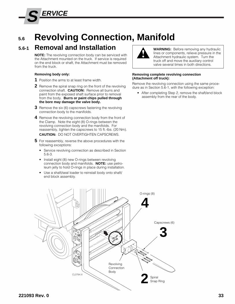
5.6-1 Removal and InstallationNOTE: The revolving connection body can be serviced withthe Attachment mounted on the truck. If service is requiredon the end block or shaft, the Attachment must be removedfrom the truck.
Removing body only:
1 Position the arms to at least frame width.
2 Remove the spiral snap ring on the front of the revolvingconnection shaft. CAUTION: Remove all burrs andpaint from the exposed shaft surface prior to removalfrom the body. Burrs or paint chips pulled throughthe bore may damage the valve body.
3 Remove the six (6) capscrews fastening the revolvingconnection body to the manifolds.
4 Remove the revolving connection body from the front ofthe Clamp. Note the eight (8) O-rings between therevolving connection body and the manifolds. Forreassembly, tighten the capscrews to 15 ft.-lbs. (20 Nm).CAUTION: DO NOT OVERTIGHTEN CAPSCREWS.
5 For reassembly, reverse the above procedures with thefollowing exceptions:
• Service revolving connection as described in Section5.6-3.
• Install eight (8) new O-rings between revolvingconnection body and manifolds. NOTE: use petro-leum jelly to hold O-rings in place during installation.
• Use a shaft/seal loader to reinstall body onto shaft/end block assembly.
WARNING: Before removing any hydrauliclines or components, relieve pressure in theAttachment hydraulic system. Turn thetruck off and move the auxiliary controlvalve several times in both directions.
CL0784.ill
RevolvingConnectionBody
3
2
O-rings (8)
SpiralSnap Ring
4Capscrews (6)

S
34 221093 Rev. 0
ERVICE
5.6-2 Manifold Removal andInstallationIMPORTANT: Removing the hydraulic manifolds requiresthat the Attachment be removed from the truck and thecomplete base unit be removed from the Attachment.
1 Remove the Attachment from the truck as described inSection 5.1.
2 Remove the revolving connection as described inSection 5.6-1
3 Remove the baseplate as described in Section 5.8.
4 Remove the capscrews fastening the manifolds to thecylinders and remove the manifolds. Keep track of theeight (8) O-rings. NOTE: 40E/45E Revolving Clampsrequire the removal of two spacer plates, to provideaccess to all manifold capscrews. For reassembly,tighten all capscrews to 20 ft-lbs. (30 Nm).
CAUTION: DO NOT OVERTIGHTEN CAPSCREWS.
5 For reassembly, reverse the above procedures with thefollowing exceptions:
• Install eight (8) new O-rings between the manifoldsand the cylinders. Use petroleum jelly to keep the O-rings in place during assembly.
CAUTION: Make sure the eight (8) O-rings are properlylocated prior to assembly to prevent leakage.
WARNING: Before removing any hydrauliclines or components, relieve pressure in thehydraulic system. Turn the truck off andmove the truck auxiliary control valvesseveral times in both directions.
CL0860.ill
Manifolds (2),Capscrews (8)
O-Rings (8)
4
5
Spacer plates (2),Capscrews (8)
Faceplate
4
S
221093 Rev. 0 35
ERVICE
CL0854.ill
Cross-overReliefCartridge
4
End BlockO-rings (2)
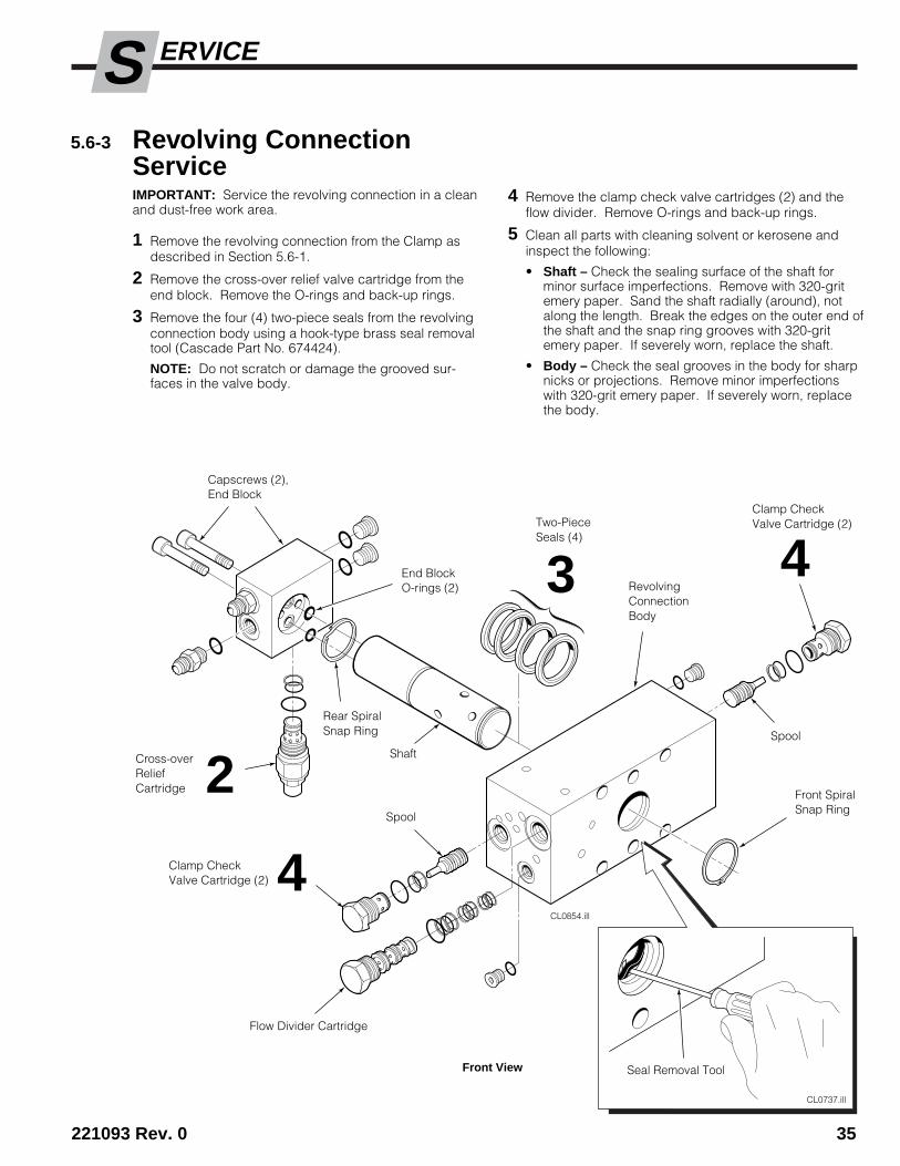
4 Remove the clamp check valve cartridges (2) and theflow divider. Remove O-rings and back-up rings.
5 Clean all parts with cleaning solvent or kerosene andinspect the following:
• Shaft – Check the sealing surface of the shaft forminor surface imperfections. Remove with 320-gritemery paper. Sand the shaft radially (around), notalong the length. Break the edges on the outer end ofthe shaft and the snap ring grooves with 320-gritemery paper. If severely worn, replace the shaft.
• Body – Check the seal grooves in the body for sharpnicks or projections. Remove minor imperfectionswith 320-grit emery paper. If severely worn, replacethe body.
5.6-3 Revolving ConnectionServiceIMPORTANT: Service the revolving connection in a cleanand dust-free work area.
1 Remove the revolving connection from the Clamp asdescribed in Section 5.6-1.
2 Remove the cross-over relief valve cartridge from theend block. Remove the O-rings and back-up rings.
3 Remove the four (4) two-piece seals from the revolvingconnection body using a hook-type brass seal removaltool (Cascade Part No. 674424).
NOTE: Do not scratch or damage the grooved sur-faces in the valve body.
2Clamp CheckValve Cartridge (2)
Flow Divider Cartridge
Clamp CheckValve Cartridge (2)
RevolvingConnectionBody
Capscrews (2),End Block
Spool
Spool
3Two-PieceSeals (4)
CL0737.ill
Seal Removal ToolFront View
Front SpiralSnap Ring
Rear SpiralSnap Ring
4
Shaft

S
36 221093 Rev. 0
ERVICE
5.6-3 Revolving ConnectionService (continued)6 For reassembly, reverse the previous procedure with the
following exceptions:
• Install new O-rings and back-up rings on all valvecartridges (see illustration below).
• Install the square rubber rings into thegrooves in the revolving connection body.
• Install the Teflon rings over the rubber rings.
NOTE: Use seal installation tool (Cascade partnumber 599512) when installing internal seals. Ifseals are installed by hand, form into 'kidney' shape toavoid sharp bends that can cause permanentdamage to seals.
• Lubricate shaft and body with STP or petroleum jellyprior to reassembly.
• Insert shaft loader if available into body and carefullyinstall shaft, displacing loader. NOTE: Rotate bodyto ease installation and prevent damage to seals.
RC0490.ill
SquareRubber Ring
CL0634.ill
CL0341.ill
Flow Divider Cartridge (PN 210266)
Check Valve Cartridge (PN 209847)Cross-Over Relief Cartridge (PN 214405)
O-rings (2)
O-rings (4)
Back-Up Rings (6)
O-rings (2)
Back-Up Rings (2)
AC0044.ill
RC0488.illInternal SealInstallation Tool
Form seals into'kidney' shapeto install
Revolving Connection Body
TeflonRing
Two-Piece Seals (3)
GA0102.ill
CAUTION: The shaft seals must beinstalled dry to work properly.
Clean all traces of hydraulic fluidand moisture from the seal groovesinside the revolving connectionbody using a non-petroleum basedelectronics contact cleaner.
Clean hands thoroughly.
CL0342.ill
Back-Up Ring (1)

S
221093 Rev. 0 37
ERVICE
5.6-4 Cross-Over Relief ValveAdjustmentFor Attachment over-pressure protection, the cross-overrelief valve cartridge for the CLAMP function should beadjusted to match the truck hydraulic flow rate.MAXIMUM RELIEF VALVE SETTING = 2600 psi (180 bar) .
1 Confirm that the truck pressure is between 2300–2600psi (160–180 bar) at the carriage hose terminal.
2 Install a 3000-psi (200 bar) pressure gauge to both theRH and LH TEST ports on the revolving connection (No.4 O-ring fittings required).
3 Cycle arms to full open. Slowly close arms whileclamping a maximum rigid load (or clamp force indica-tor). Hold lever in the CLAMP position and accelerateengine to develop full system pressure.
4 Adjust the crossover relief cartridge for an indicated2300 psi (160 bar). Turn clockwise to increase pres-sure, counterclockwise to decrease pressure. Tightenjam nut and replace cap.
WARNING: Before removing hydrauliclines or components, relieve pressure inthe Attachment hydraulic system. Turn thetruck off and move the auxiliary controlvalve several times in both directions.
CL0859.illFront View
2Pressure gaugesconnected to bothTEST ports onrevolving connection
3
CL0725.ill
CLAMP
OPEN
CLAMP Cross-overRelief Valve Cartridge
4Back (Driver's) View

S
38 221093 Rev. 0
ERVICE
Purging cylinders of hydraulic fluid
5 Completely retract the cylinders, then bump the controlvalve open to release any trapped pressure behind thecheck valves.
6 At the hose terminal, disconnect the supply hose to therevolving connection OPEN port and plug the supply.Route the hose end to a drain bucket. NOTE: This hosebleeds air into the cylinders when purging. Make surethe hose end is not submerged in hydraulic fluid.
7 Install a No. 4 O-ring fitting and drain hose to both theLH and RH TEST ports on the revolving connection.Route the hose ends to a drain bucket.
8 Starting with the bottom cylinder fully retracted,manually pull the cylinder rod fully out to removehydraulic fluid from the shell. Leave the cylinder fullyextended. Repeat the procedure for each cylinder,progressing to the next cylinder above.
5.7 Cylinders5.7-1 Cylinder Service
The cylinders can be serviced with the Attachmentmounted on the truck by using the following procedure. Ifpreliminary inspection reveals external damage, replacethe complete cylinder (see Section 5.7-5).
5.7-2 Cylinder DisassemblyNOTE: All four cylinders should be serviced if trouble-shooting reveals that one cylinder is faulty or leaking.
1 Close the arms completely.
2 Remove the capscrews fastening the cylinder rodanchor bars to the arms.
3 Slowly power the cylinder rods outward 3 in. (7 cm) toexpose the rod end and split ring keepers.
4 Slide the rod end inward to remove the split ringkeepers. Slide the rod end off the cylinder rod.
CL0311.ill
CLAMP
OPEN
CL0785.ill
42
6
CL0786.ill
1
Front View
8Front View
CL0870.ill
Rear (Driver's) View
7Drain hosesfrom TESTports (2)
CylinderRod
WARNING: Before disconnecting hoses,relieve pressure in the Attachmenthydraulic system. Turn the truck off andmove the auxiliary control valve severaltimes in both directions.
S
221093 Rev. 0 39
ERVICE
5.7-2 Cylinder Disassembly(Continued)
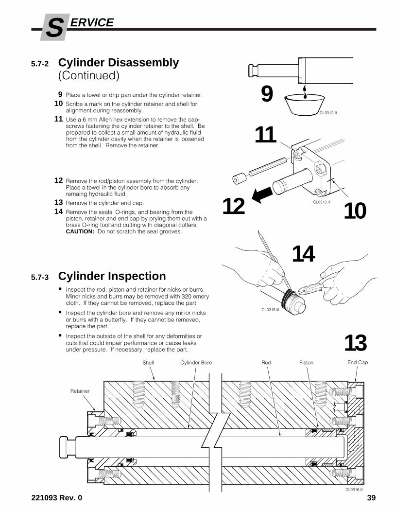
9 Place a towel or drip pan under the cylinder retainer.
10 Scribe a mark on the cylinder retainer and shell foralignment during reassembly.
11 Use a 6 mm Allen hex extension to remove the cap-screws fastening the cylinder retainer to the shell. Beprepared to collect a small amount of hydraulic fluidfrom the cylinder cavity when the retainer is loosenedfrom the shell. Remove the retainer.
CL0313.ill
12 Remove the rod/piston assembly from the cylinder.Place a towel in the cylinder bore to absorb anyremaing hydraulic fluid.
13 Remove the cylinder end cap.
14 Remove the seals, O-rings, and bearing from thepiston, retainer and end cap by prying them out with abrass O-ring tool and cutting with diagonal cutters.CAUTION: Do not scratch the seal grooves.
CL0315.ill
Cylinder Bore
����� ������ ����� ��������������������������������� ������
��������
���
����������
������������
CL0316.ill
Rod Piston
Retainer
9
11
12 10
14
End Cap
5.7-3 Cylinder Inspection• Inspect the rod, piston and retainer for nicks or burrs.
Minor nicks and burrs may be removed with 320 emerycloth. If they cannot be removed, replace the part.
• Inspect the cylinder bore and remove any minor nicksor burrs with a butterfly. If they cannot be removed,replace the part.
• Inspect the outside of the shell for any deformities orcuts that could impair performance or cause leaksunder pressure. If necessary, replace the part.
Shell
CL0312.ill
13
S
40 221093 Rev. 0
ERVICE
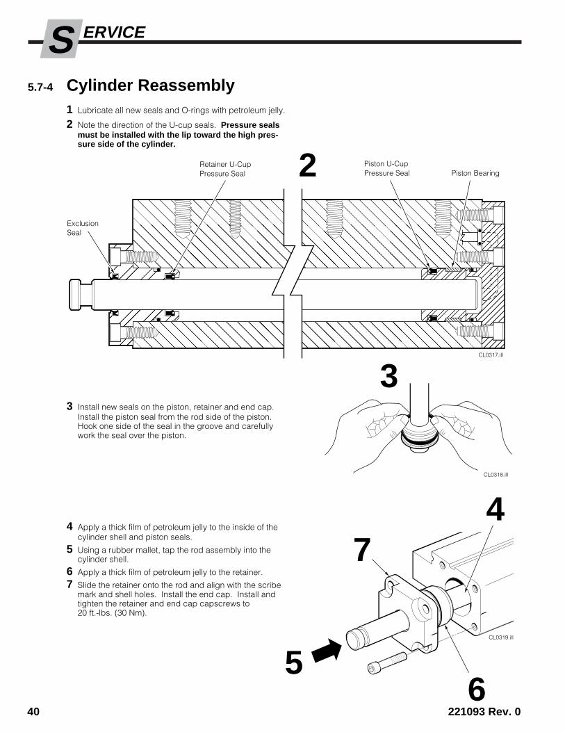
3 Install new seals on the piston, retainer and end cap.Install the piston seal from the rod side of the piston.Hook one side of the seal in the groove and carefullywork the seal over the piston.
4 Apply a thick film of petroleum jelly to the inside of thecylinder shell and piston seals.
5 Using a rubber mallet, tap the rod assembly into thecylinder shell.
6 Apply a thick film of petroleum jelly to the retainer.
7 Slide the retainer onto the rod and align with the scribemark and shell holes. Install the end cap. Install andtighten the retainer and end cap capscrews to20 ft.-lbs. (30 Nm).
5.7-4 Cylinder Reassembly1 Lubricate all new seals and O-rings with petroleum jelly.
2 Note the direction of the U-cup seals. Pressure sealsmust be installed with the lip toward the high pres-sure side of the cylinder.
CL0317.ill����� ������ ����� ��������������������������������� ������
��������
���
����������
������������
Retainer U-CupPressure Seal
Piston U-CupPressure Seal
CL0318.ill
CL0319.ill
3
74
65
2
ExclusionSeal
Piston Bearing
S
221093 Rev. 0 41
ERVICE
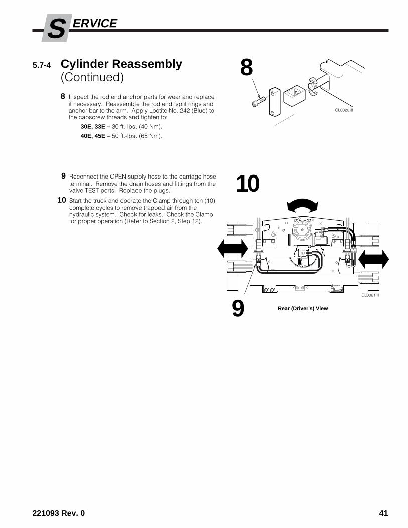
5.7-4 Cylinder Reassembly(Continued)8 Inspect the rod end anchor parts for wear and replace
if necessary. Reassemble the rod end, split rings andanchor bar to the arm. Apply Loctite No. 242 (Blue) tothe capscrew threads and tighten to:
30E, 33E – 30 ft.-lbs. (40 Nm).
40E, 45E – 50 ft.-lbs. (65 Nm).
9 Reconnect the OPEN supply hose to the carriage hoseterminal. Remove the drain hoses and fittings from thevalve TEST ports. Replace the plugs.
10 Start the truck and operate the Clamp through ten (10)complete cycles to remove trapped air from thehydraulic system. Check for leaks. Check the Clampfor proper operation (Refer to Section 2, Step 12).
CL0320.ill
CLAMP
OPEN
CL0861.ill
8
9
10
Rear (Driver's) View
S
42 221093 Rev. 0
ERVICE
CL0692.ill
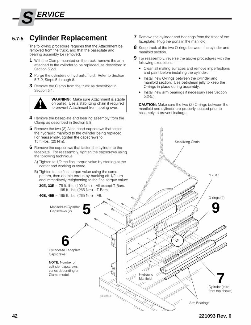
5.7-5 Cylinder ReplacementThe following procedure requires that the Attachment beremoved from the truck, and that the baseplate andbearing assembly be removed.
1 With the Clamp mounted on the truck, remove the armattached to the cylinder to be replaced, as described inSection 5.2-1.
2 Purge the cylinders of hydraulic fluid. Refer to Section5.7-2, Steps 5 through 8.
3 Remove the Clamp from the truck as described inSection 5.1.
4 Remove the baseplate and bearing assembly from theClamp as described in Section 5.8.
5 Remove the two (2) Allen head capscrews that fastenthe hydraulic manifold to the cylinder being replaced.For reassembly, tighten the capscrews to15 ft.-lbs. (20 Nm).
6 Remove the capscrews that fasten the cylinder to thefaceplate. For reassembly, tighten the capscrews usingthe following technique:
A) Tighten to 1/2 the final torque value by starting at thecenter and working outward.
B) Tighten to the final torque value using the samepattern, then double-torque by backing off 1/2 turnand immediately retightening to the final torque value:
30E, 33E – 75 ft.-lbs. (100 Nm ) – All except T-Bars.195 ft.-lbs. (265 Nm) – T-Bars.
40E, 45E – 195 ft.-lbs. (265 Nm) – All.
WARNING: Make sure Attachment is stableon pallet. Use a stabilizing chain if requiredto prevent Attachment from tipping over.
7 Remove the cylinder and bearings from the front of thefaceplate. Plug the ports in the manifold.
8 Keep track of the two O-rings between the cyinder andmanifold section.
9 For reassembly, reverse the above procedures with thefollowing exceptions:
• Clean all mating surfaces and remove imperfectionsand paint before installing the cylinder.
• Install new O-rings between the cylinder andmanifold section. Use petroleum jelly to keep theO-rings in place during assembly.
• Install new arm bearings if necessary (see Section5.2-5.).
CAUTION: Make sure the two (2) O-rings between themanifold and cylinder are properly located prior toassembly to prevent leakage.
Manifold-to-CylinderCapscrews (2) 5
Cylinder-to FaceplateCapscrews
NOTE: Number ofcylinder capscrewsvaries depending onClamp model.
6
Arm Bearings
7HydraulicManifold
Cylinder (thirdfrom top shown)
9O-rings (2)
Stabilizing Chain
'T'-Bar
S
221093 Rev. 0 43
ERVICE
ca
sc
ad
e
C-675514-1
ca
sc
ad
e
C-675514-1
CL0788.ill
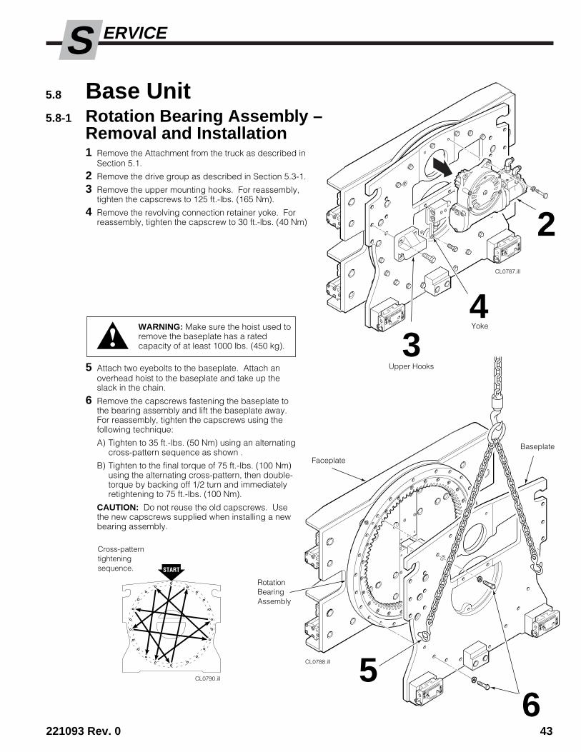
5 Attach two eyebolts to the baseplate. Attach anoverhead hoist to the baseplate and take up theslack in the chain.
6 Remove the capscrews fastening the baseplate tothe bearing assembly and lift the baseplate away.For reassembly, tighten the capscrews using thefollowing technique:
A) Tighten to 35 ft.-lbs. (50 Nm) using an alternatingcross-pattern sequence as shown .
B) Tighten to the final torque of 75 ft.-lbs. (100 Nm)using the alternating cross-pattern, then double-torque by backing off 1/2 turn and immediatelyretightening to 75 ft.-lbs. (100 Nm).
CAUTION: Do not reuse the old capscrews. Usethe new capscrews supplied when installing a newbearing assembly.
5.8-1 Rotation Bearing Assembly –Removal and Installation1 Remove the Attachment from the truck as described in
Section 5.1.
2 Remove the drive group as described in Section 5.3-1.
3 Remove the upper mounting hooks. For reassembly,tighten the capscrews to 125 ft.-lbs. (165 Nm).
4 Remove the revolving connection retainer yoke. Forreassembly, tighten the capscrew to 30 ft.-lbs. (40 Nm)
CL0787.ill
ca
sc
ad
e
C-675514-1
ca
sc
ad
e
C-675514-1
2
3
65
RotationBearingAssembly
Faceplate
Baseplate
4
CL0790.ill
Cross-patterntighteningsequence.
WARNING: Make sure the hoist used toremove the baseplate has a ratedcapacity of at least 1000 lbs. (450 kg).
5.8 Base Unit
Upper Hooks
Yoke
S
44 221093 Rev. 0
ERVICE
CL0789.ill
5.8-1 Rotation Bearing Assembly –Removal and Installation (Continued)
87
Faceplate
CL0875.ill
R
9
Back (Driver's) View
Greasefitting
Heat treatzone
30°
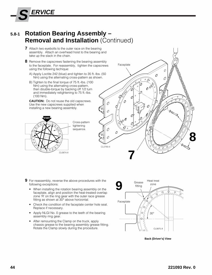
7 Attach two eyebolts to the outer race on the bearingassembly. Attach an overhead hoist to the bearing andtake up the slack in the chain.
8 Remove the capscrews fastening the bearing assemblyto the faceplate. For reassembly, tighten the capscrewsusing the following techique:
A) Apply Loctite 242 (blue) and tighten to 35 ft.-lbs. (50Nm) using the alternating cross-pattern as shown.
B) Tighten to the final torque of 75 ft.-lbs. (100Nm) using the alternating cross-pattern,then double-torque by backing off 1/2 turnand immediately retightening to 75 ft.-lbs.(100 Nm).
CAUTION: Do not reuse the old capscrews.Use the new capscrews supplied wheninstalling a new bearing assembly.
9 For reassembly, reverse the above procedures with thefollowing exceptions:
• When installing the rotation bearing assembly on thefaceplate, align and position the heat-treated overlapzone 'R' on the ring gear with the outer race greasefitting as shown at 30° above horizontal.
• Check the condition of the faceplate center hole seal.Replace if necessary.
• Apply NLGI No. 0 grease to the teeth of the bearingassembly ring gear.
• After remounting the Clamp on the truck, applychassis grease to the bearing assembly grease fitting.Rotate the Clamp slowly during the procedure.
CL0874.ill
Cross-patterntighteningsequence.
Faceplate
S
221093 Rev. 0 45
ERVICE
5.9 180-Degree Stop Group5.9-1 Stop Valve Adjustment
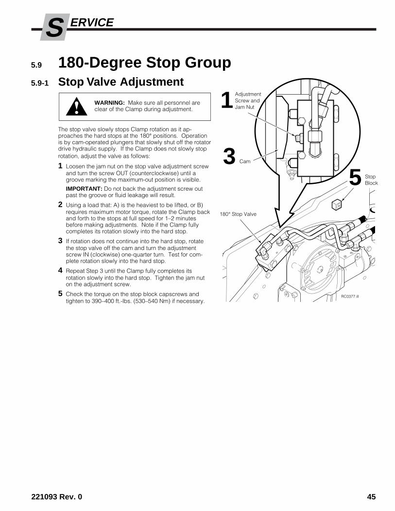
The stop valve slowly stops Clamp rotation as it ap-proaches the hard stops at the 180° positions. Operationis by cam-operated plungers that slowly shut off the rotatordrive hydraulic supply. If the Clamp does not slowly stoprotation, adjust the valve as follows:
1 Loosen the jam nut on the stop valve adjustment screwand turn the screw OUT (counterclockwise) until agroove marking the maximum-out position is visible.
IMPORTANT: Do not back the adjustment screw outpast the groove or fluid leakage will result.
2 Using a load that: A) is the heaviest to be lifted, or B)requires maximum motor torque, rotate the Clamp backand forth to the stops at full speed for 1–2 minutesbefore making adjustments. Note if the Clamp fullycompletes its rotation slowly into the hard stop.
3 If rotation does not continue into the hard stop, rotatethe stop valve off the cam and turn the adjustmentscrew IN (clockwise) one-quarter turn. Test for com-plete rotation slowly into the hard stop.
4 Repeat Step 3 until the Clamp fully completes itsrotation slowly into the hard stop. Tighten the jam nuton the adjustment screw.
5 Check the torque on the stop block capscrews andtighten to 390–400 ft.-lbs. (530–540 Nm) if necessary.
RC0377.ill
1
180° Stop Valve
Cam35 Stop
Block
WARNING: Make sure all personnel areclear of the Clamp during adjustment.
AdjustmentScrew andJam Nut
S
46 221093 Rev. 0
ERVICE
RC0204.ill
2 3
4
Coil
Solenoid ValveAssembly
5.10 Solenoid Valve5.10-1 Coil Service
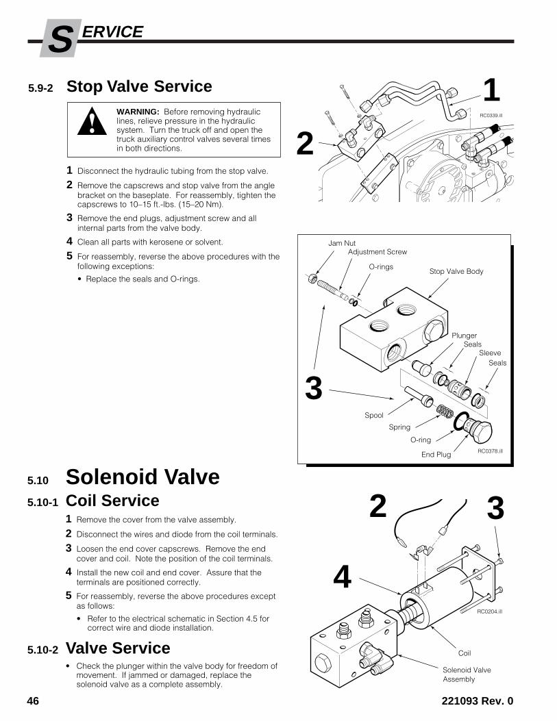
1 Remove the cover from the valve assembly.
2 Disconnect the wires and diode from the coil terminals.
3 Loosen the end cover capscrews. Remove the endcover and coil. Note the position of the coil terminals.
4 Install the new coil and end cover. Assure that theterminals are positioned correctly.
5 For reassembly, reverse the above procedures exceptas follows:
• Refer to the electrical schematic in Section 4.5 forcorrect wire and diode installation.
5.10-2 Valve Service• Check the plunger within the valve body for freedom of
movement. If jammed or damaged, replace thesolenoid valve as a complete assembly.
5.9-2 Stop Valve Service
1 Disconnect the hydraulic tubing from the stop valve.
2 Remove the capscrews and stop valve from the anglebracket on the baseplate. For reassembly, tighten thecapscrews to 10–15 ft.-lbs. (15–20 Nm).
3 Remove the end plugs, adjustment screw and allinternal parts from the valve body.
4 Clean all parts with kerosene or solvent.
5 For reassembly, reverse the above procedures with thefollowing exceptions:
• Replace the seals and O-rings.
WARNING: Before removing hydrauliclines, relieve pressure in the hydraulicsystem. Turn the truck off and open thetruck auxiliary control valves several timesin both directions.
End Plug RC0378.ill
O-ring
Spring
Spool
SealsSleeve
Seals
Stop Valve Body
Plunger
O-rings
Adjustment ScrewJam Nut
3
RC0339.ill
2
1
221093 Rev. 0 47
PECIFICATIONSS
GA0091.ill
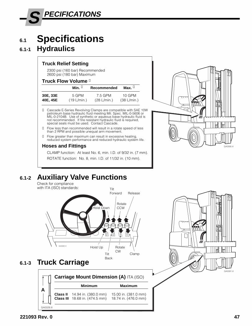
6.1 Specifications6.1-1 Hydraulics
6.1-3 Truck Carriage
GA0090.ill
TiltBack
GA0082.ill
Clamp
RotateCW
TiltForward
Hoist Up
Hoist Down
Release
RotateCCW
GA0028.ill
Carriage Mount Dimension (A) ITA (ISO)
Minimum Maximum
Class II 14.94 in. (380.0 mm) 15.00 in. (381.0 mm)Class III 18.68 in. (474.5 mm) 18.74 in. (476.0 mm)
6.1-2 Auxiliary Valve FunctionsCheck for compliancewith ITA (ISO) standards:
Truck Relief Setting2300 psi (160 bar) Recommended2600 psi (180 bar) Maximum
Truck Flow Volume ➀
Min. ➁ Recommended Max. ➂
30E, 33E 5 GPM 7.5 GPM 10 GPM40E, 45E (19 L/min.) (28 L/min.) (38 L/min.)
➀ Cascade E-Series Revolving Clamps are compatible with SAE 10Wpetroleum base hydraulic fluid meeting Mil. Spec. MIL-0-5606 orMIL-0-2104B. Use of synthetic or aqueous base hydraulic fluid isnot recommended. If fire resistant hydraulic fluid is required,special seals must be used. Contact Cascade.
➁ Flow less than recommended will result in a rotate speed of lessthan 2 RPM and possible unequal arm movement.
➂ Flow greater than maximum can result in excessive heating,reduced system performance and reduced hydraulic system life.
Hoses and FittingsCLAMP function: At least No. 6, min. I.D. of 9/32 in. (7 mm).
ROTATE function: No. 8, min. I.D. of 11/32 in. (10 mm).
A
48 221093 Rev. 0
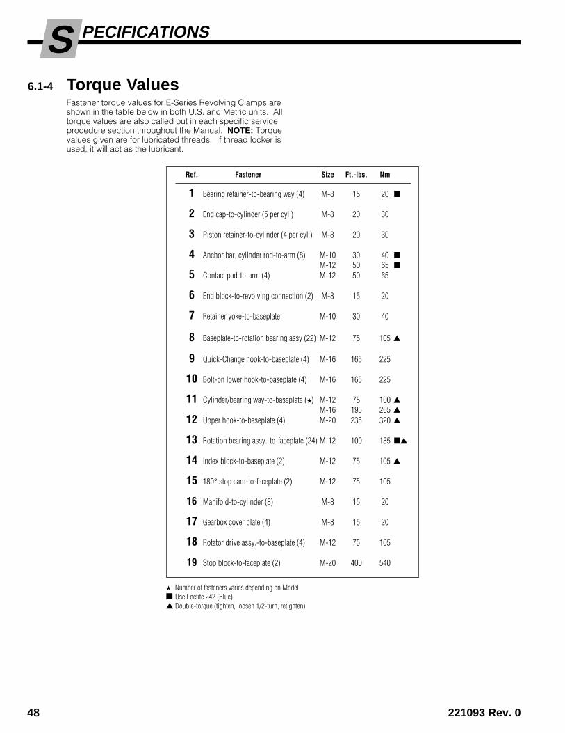
PECIFICATIONSS6.1-4 Torque Values
Fastener torque values for E-Series Revolving Clamps areshown in the table below in both U.S. and Metric units. Alltorque values are also called out in each specific serviceprocedure section throughout the Manual. NOTE: Torquevalues given are for lubricated threads. If thread locker isused, it will act as the lubricant.
Ref. Fastener Size Ft.-lbs. Nm
1 Bearing retainer-to-bearing way (4) M-8 15 20 ■
2 End cap-to-cylinder (5 per cyl.) M-8 20 30
3 Piston retainer-to-cylinder (4 per cyl.) M-8 20 30
4 Anchor bar, cylinder rod-to-arm (8) M-10 30 40 ■M-12 50 65 ■
5 Contact pad-to-arm (4) M-12 50 65
6 End block-to-revolving connection (2) M-8 15 20
7 Retainer yoke-to-baseplate M-10 30 40
8 Baseplate-to-rotation bearing assy (22) M-12 75 105 ▲
9 Quick-Change hook-to-baseplate (4) M-16 165 225
10 Bolt-on lower hook-to-baseplate (4) M-16 165 225
11 Cylinder/bearing way-to-baseplate (★) M-12 75 100 ▲M-16 195 265 ▲
12 Upper hook-to-baseplate (4) M-20 235 320 ▲
13 Rotation bearing assy.-to-faceplate (24) M-12 100 135 ■▲
14 Index block-to-baseplate (2) M-12 75 105 ▲
15 180° stop cam-to-faceplate (2) M-12 75 105
16 Manifold-to-cylinder (8) M-8 15 20
17 Gearbox cover plate (4) M-8 15 20
18 Rotator drive assy.-to-baseplate (4) M-12 75 105
19 Stop block-to-faceplate (2) M-20 400 540
★ Number of fasteners varies depending on Model■ Use Loctite 242 (Blue)▲ Double-torque (tighten, loosen 1/2-turn, retighten)

221093 Rev. 0 49
PECIFICATIONSS
CL0682.ill
CL0683.ill
7
16
11
10
1213
1
2
4
5
9
15
8
17 18 19
614
(Capscrewsaccessedthrough plug)
3

390122 rebmuN traP 99-2 9991 noitaroproC edacsaC
c
Do you have questions you need answered right now? Call your nearest Cascade Service Department.Visit us online at www.cascorp.com
AMERICASCascade CorporationU.S. Headquarters2201 NE 201stFairview, OR 97024-9718Tel: 800-CASCADE (227-2233)Fax: 888-329-8207
Cascade Canada Inc.5570 Timberlea Blvd.Mississauga, OntarioCanada L4W-4M6Tel: 905-629-7777Fax: 905-629-7785
Cascade do BrasilRua João Guerra, 134Macuco, Santos - SPBrasil 11015-130Tel: 55-13-2105-8800Fax: 55-13-2105-8899
EUROPE-AFRICACascade Italia S.R.L.European HeadquartersVia Dell’Artigianato 137050 Vago di Lavagno (VR) ItalyTel: 39-045-8989111Fax: 39-045-8989160
Cascade (Africa) Pty. Ltd.PO Box 625, Isando 160060A Steel RoadSparton, Kempton ParkSouth AfricaTel: 27-11-975-9240Fax: 27-11-394-1147
ASIA-PACIFICCascade Japan Ltd.2-23, 2-Chome,Kukuchi NishimachiAmagasaki, Hyogo Japan, 661-0978Tel: 81-6-6420-9771Fax: 81-6-6420-9777
Cascade Korea121B 9L Namdong Ind. Complex, 691-8 Gojan-DongNamdong-KuInchon, KoreaTel: +82-32-821-2051Fax: +82-32-821-2055
Cascade-XiamenNo. 668 Yangguang Rd. Xinyang Industrial ZoneHaicang, Xiamen CityFujian ProvinceP.R. China 361026Tel: 86-592-651-2500Fax: 86-592-651-2571
Cascade India Material Handling Private LimitedNo 34, Global Trade Centre 1/1 Rambaugh ColonyLal Bahadur Shastri Road, Navi Peth, Pune 411 030(Maharashtra) IndiaPhone: +91 020 2432 5490Fax: +91 020 2433 0881
Cascade Australia Pty. Ltd.1445 Ipswich RoadRocklea, QLD 4107AustraliaTel: 1-800-227-223Fax: +61 7 3373-7333
Cascade New Zealand15 Ra Ora DriveEast Tamaki, AucklandNew ZealandTel: +64-9-273-9136Fax: +64-9-273-9137
Sunstream IndustriesPte. Ltd.18 Tuas South Street 5Singapore 637796Tel: +65-6795-7555Fax: +65-6863-1368