2.2.1 NI-CAS Software for Development Hardware Setup - National
196
NI Combustion Analysis System Software for LabVIEW User's Manual © National Instruments. All rights reserved. 1 NI Combustion Analysis System Software for LabVIEW™ User's Manual Web : http://www.ni.com/powertrain-controls , E-mail : [email protected]
Transcript of 2.2.1 NI-CAS Software for Development Hardware Setup - National

NI Combustion Analysis System Software for LabVIEWUser's Manual
© National Instruments. All rights reserved. 1
NI Combustion Analysis System Software for LabVIEW™User's Manual
Web : http://www.ni.com/powertrain-controls, E-mail : [email protected]

NI Combustion Analysis System Software for LabVIEWUser's Manual
© National Instruments. All rights reserved. 2
Table of Contents1. Product Introduction ...................................................................................................................................5
1.1 Features By License Version .............................................................................................................61.2 Data Flow .........................................................................................................................................10
2. Getting Started .........................................................................................................................................112.1 Recommended System Requirements ............................................................................................12
2.1.1 Supported C Series Modules ..................................................................................................152.2 Hardware Configuration ...................................................................................................................16
2.2.1 Development Version Hardware Setup ...................................................................................172.2.2 Deployment Version Hardware Setup .....................................................................................19
2.3 Software Configuration .....................................................................................................................232.3.1 Activating Your Software .........................................................................................................242.3.2 MAX Hardware Configuration .................................................................................................26
2.2.2.1 Development Version MAX Hardware Configuration .....................................................272.2.2.2 Deployment Version MAX Hardware Configuration .......................................................29
2.3.3 Development Version Example Project and System Integration .............................................302.4 Performance .....................................................................................................................................32
2.4.1 Development Version Performance Overview ........................................................................332.4.1.1 S Series Hardware .........................................................................................................342.4.1.2 HDD ................................................................................................................................35
2.4.2 Deployment Version Performance Overview ..........................................................................362.4.2.1 cDAQ Hardware .............................................................................................................372.4.2.2 NI cDAQ-1939 Benchmark .............................................................................................38
3. NI CAS Software Interface .......................................................................................................................393.1 Offline ...............................................................................................................................................41
3.1.1 General Setup .........................................................................................................................423.1.1.1 Project Setup ..................................................................................................................433.1.1.2 Engine Geometry Setup .................................................................................................443.1.1.3 Encoder Setup ................................................................................................................463.1.1.4 Calculations ....................................................................................................................483.1.1.5 Next-Cycle Calculations .................................................................................................493.1.1.6 System Optimization ......................................................................................................50
3.1.2 IO Hardware Setup .................................................................................................................513.1.2.1 Sample Rates Setup ......................................................................................................523.1.2.2 Sync Analog Channels Setup ........................................................................................533.1.2.3 Sync Digital Channels Setup .........................................................................................553.1.2.4 Async Analog Channels Setup ......................................................................................563.1.2.5 Async Digital Channels Setup ........................................................................................583.1.2.6 Medium Speed Channels Setup ....................................................................................593.1.2.7 FPGA Stream Setup ......................................................................................................613.1.2.8 Analog Output Channels Setup .....................................................................................62
3.2 Online ...............................................................................................................................................633.2.1 Settings ....................................................................................................................................64
3.2.1.1 Motoring and TDC Offset Settings .................................................................................653.2.1.2 Async Conversion Settings ............................................................................................673.2.1.3 Pegging Settings ............................................................................................................68

NI Combustion Analysis System Software for LabVIEWUser's Manual
© National Instruments. All rights reserved. 3
3.2.1.4 Filter Settings .................................................................................................................693.2.1.5 Pressure Metrics Settings ..............................................................................................703.2.1.6 Unit Conversions Settings ..............................................................................................723.2.1.7 Temperature Settings .....................................................................................................733.2.1.8 Heat Release Settings ...................................................................................................743.2.1.9 Knock Settings ...............................................................................................................763.2.1.10 Cam Settings ................................................................................................................803.2.1.11 Injection Settings ..........................................................................................................813.2.1.12 Spark Settings ..............................................................................................................823.2.1.13 Misfire Settings .............................................................................................................833.2.1.14 Simulation Settings .......................................................................................................84
3.2.2 File Save .................................................................................................................................863.2.2.1 Raw File Save ................................................................................................................873.2.2.2 Summary File Save ........................................................................................................89
3.2.3 Status .......................................................................................................................................913.2.3.1 Engine .............................................................................................................................923.2.3.2 Resources .......................................................................................................................933.2.3.3 EPT .................................................................................................................................943.2.3.4 Execution ........................................................................................................................953.2.3.5 Buffer ..............................................................................................................................963.2.3.6 Loop ................................................................................................................................983.2.3.7 Error ................................................................................................................................99
3.3 Results ............................................................................................................................................1003.3.1 X-Axis ....................................................................................................................................1013.3.2 Plots .......................................................................................................................................1023.3.3 Tables ....................................................................................................................................1083.3.4 Trend Charts ..........................................................................................................................109
4. Processing and Calculations ..................................................................................................................1104.1 Cylinder Volume .............................................................................................................................1114.2 Waveform Filters ............................................................................................................................113
4.2.1 Boxcar ....................................................................................................................................1144.2.2 Rolling N Cycles ....................................................................................................................1154.2.3 Forward and Reverse IIR ......................................................................................................1164.2.4 FIR Filter with Rollback .........................................................................................................117
4.3 Cylinder Pressure Pegging ............................................................................................................1184.3.1 Constant ................................................................................................................................1194.3.2 Synchronous MAP .................................................................................................................1204.3.3 Polytropic ...............................................................................................................................121
4.4 Pressure Metrics ............................................................................................................................1224.4.1 Pressure and Pressure Rise Rate ........................................................................................1234.4.2 Polytropic Coefficients ...........................................................................................................1244.4.3 TDC Probe ............................................................................................................................126
4.5 Mean Effective Pressure ................................................................................................................1274.6 Motoring Pressure ..........................................................................................................................1284.7 Global Gas Temperature ................................................................................................................1294.8 Injector ............................................................................................................................................130

NI Combustion Analysis System Software for LabVIEWUser's Manual
© National Instruments. All rights reserved. 4
4.9 Heat Release ..................................................................................................................................1374.9.1 Heat Release Models ............................................................................................................138
4.9.1.1 Single Zone ..................................................................................................................1394.9.1.2 Single Zone + Heat Transfer ........................................................................................1404.9.1.3 Single Zone Dual Transducer ......................................................................................1414.9.1.4 Single Zone Dual Transducer + Heat Transfer ............................................................1424.9.1.5 Modified Rassweiler and Withrow ................................................................................1434.9.1.6 Pressure Ratio ..............................................................................................................144
4.9.2 Heat Transfer Correlations ....................................................................................................1454.9.2.1 Constant .......................................................................................................................1464.9.2.2 Woschni 1967 ...............................................................................................................1474.9.2.3 Woschni 1990 ...............................................................................................................1484.9.2.4 Hohenberg ....................................................................................................................149
4.9.3 Polytropic Correlation ............................................................................................................1504.9.3.1 Hayes (SAE860029) .....................................................................................................1514.9.3.2 Indolene (SAE841359) .................................................................................................1524.9.3.3 Propane (SAE841359) .................................................................................................1534.9.3.4 Custom .........................................................................................................................154
4.9.4 Start and End of Combustion ...............................................................................................1554.10 Combustion Noise ........................................................................................................................1574.11 Misfire ...........................................................................................................................................1584.12 Cam ..............................................................................................................................................1594.13 Synchronous Pump ......................................................................................................................1604.14 PWM .............................................................................................................................................1614.15 Knock ............................................................................................................................................1624.16 Spark ............................................................................................................................................1634.17 Custom User VIs ..........................................................................................................................167
5. Post Processing .....................................................................................................................................1725.1 NI CAS Software File Structure .....................................................................................................1735.2 Summary Files ...............................................................................................................................1765.3 Raw Files ........................................................................................................................................1775.4 TDMS Files .....................................................................................................................................1795.5 Batch Processing ...........................................................................................................................181
6. Troubleshooting ......................................................................................................................................1837. Abbreviations ..........................................................................................................................................1878. Additional Support/Feedback .................................................................................................................1899. Important Information .............................................................................................................................190
9.1 Warranty .........................................................................................................................................1919.2 Copyright ........................................................................................................................................1929.3 Trademarks .....................................................................................................................................1939.4 Patents ............................................................................................................................................1949.5 Warning Regarding Use of NI Products ........................................................................................1959.6 Environmental Management ..........................................................................................................196

NI Combustion Analysis System Software for LabVIEWUser's Manual
© National Instruments. All rights reserved. 5
1. Product Introduction The NI Combustion Analysis System Software for LabVIEW (NI CAS) is a unique LabVIEW plug-in for performingsophisticated in-cylinder combustion analysis and data logging for engine research and development targetedto a wide variety of NI Hardware. When licensed as a toolkit it can be used to develop sophisticated PXI-basedcombustion analysis applications with real-time feedback control capabilities. Licensed as an executable, it can bedeployed to portable, low-cost cDAQ hardware. NI CAS Software allows streaming of raw data to file continuously, by cycle count, time, or file size. Raw data filesare stored in National Instrument's popular TDMS format and include all channel configurations, engine geometryand custom test data to allow complete reconstruction of the test environment at a later date. Cycle-by-cyclesummaries of analysis parameters can also be logged to TDMS files for later review. The TDMS file format is anopen format allowing these files to be post-processed with a variety of tools, including the NI CAS Software Post-Processing tools, NI DIAdem, or Microsoft Excel. License Versions
Development LicenseThe Development License of NI CAS Software enables a LabVIEW toolkit for users to integrate sophisticatedcombustion analysis and data logging with engine control applications. The toolkit includes many analysisfunctions, front panel controls, and utilities including data-streaming-to-disk, pre-processing, heat release,pressure metrics, knock analysis, noise analysis, raw data logging, summary data reporting and post-processing.
The NI CAS Software for Development leverages R Series (FPGA), S Series (simultaneous analogsampling) and M Series (Multiplexed analog sampling) PXI devices from National Instruments to superviseengine position tracking and synchronization of data collection and processing. SCXI hardware can beleveraged for medium-speed data collection which is subsequently aligned with engine-synchronous data.This software can be targeted to a wide variety of PXI real-time controllers depending on the applicationperformance requirements. The Development Version of NI CAS Software example application may be used stand-alone or integratedwith an engine control application.
Deployment License
The Deployment License enables deployment to low-cost, easy-to-use, portable engine combustion analysishardware bundles. NI CAS Software for Deployment is a pre-built NI LabVIEW Runtime executable forMicrosoft Windows, targeting cDAQ hardware over USB and Ethernet, or Stand-Alone cDAQ chassis. Overfifty NI C Series I/O modules can be added to any available slot of an NI cDAQ chassis to meet a variety ofapplication needs.
The Deployment Version of NI CAS Software supports three time-bases: high-speed engine-synchronous,high-speed angular-window time domain and medium-speed time domain. The Deployment License includesall of the analysis functions included in the Development Version of NI CAS Software toolkit except forNext-Cycle control and FPGA based Engine Position Tracking (EPT) functions. Engine synchronous datasampling must take place using optical shaft encoders mounted to the crankshaft.

NI Combustion Analysis System Software for LabVIEWUser's Manual
© National Instruments. All rights reserved. 6
1.1 Features By License Version
License Version
Highlighted Features Development Deployment
• Open source example projects for integration with real-time controlapplications
X
• Next-cycle control capabilities X
• FPGA based high speed signal processing X
• Low-cost, feature rich, turnkey bundled system X
License Version
Measurement Configuration and Engine Geometry Development Deployment
• Individual channel scaling features• Cylinder Assignment• Gain• Gain + Offset• Polynomial• Table Lookup
X X
• Channels can be assigned to all cylinders as references such as pegging X X
• Simultaneous engine-synchronous and engine-asynchronousmeasurements
X X
• Medium Speed Data (Sampled at a fixed frequency ~1kHz or less)• Thermocouples• Slow Speed Pressures• Other
X X
• Supports FPGA Data (Sampled based on FPGA setup, enginesynchronous and/or asynchronous)
X
• Digital outputs for sample clock and active high during logging X X
• Supports multiple S Series devices for simultaneous sampling of signalsin both engine-synchronous (cylinder pressure, etc.) and engine-asynchronous (knock, etc.) domains
X
• Supports 1 M Series device for multiplexed sampling of signals engine-synchronously (cylinder pressure, etc.)
X X

NI Combustion Analysis System Software for LabVIEWUser's Manual
© National Instruments. All rights reserved. 7
• Supports 1 cDAQ chassis and multiple C Series devices for simultaneoussampling of signals in both engine-synchronous (cylinder pressure, etc.)and engine-asynchronous (knock, etc.) domains
X X
Support for mapping calculated parameters to analog output channels X X
• Complete set of engine geometry inputs for cylinder volume calculation• Optionally load volume from file
X X
• Online motoring test assists with engine geometry verification X X
• TDC probe channel configuration and analysis X X
• Allows online adjustment of TDC index (< +/- 2 CAD) X X
License Version
FPGA Based Engine Position Tracking and Sample Clock Generation Development Deployment
• Use traditional optical encoder setup with advanced triggering options X
• Flexible crankshaft encoder signal processing and filtering X
• Use of pressure signal for 4-stroke cam phase information X
• Use of cam phase signal as half cycle gate for TDC index X
• Use of Engine Position Tracking (EPT) block for extrapolation of lowerresolution production trigger wheels for high resolution sampling andcontrol
X
License Version
File Saving Development Deployment
• Supports simultaneous streaming of raw and summary data to TDMS filecontinuously, by cycle count, time, or file size
X X
• Raw data files include channel configuration, engine geometry, and testdata to allow full reconstruction of the test environment in post-processing
X X
• Supports an external hardware trigger for file saving X X
• Saves all non-NI CAS Software related CalPoints, e.g., engine controls X

NI Combustion Analysis System Software for LabVIEWUser's Manual
© National Instruments. All rights reserved. 8
License Version
Pre-Processing Development Deployment
• Cylinder alignment of data in both engine-synchronous and engine-asynchronous domains
X X
• Data scaling to engineering units X X
• Broad range of signal filtering options X X
• Cylinder pressure pegging options X X
• Optional user developed LabVIEW VI X X
License Version
Pressure Metrics Development Deployment
• Peak Pressure and Location X X
• Polytropic coefficients of compression and expansion X X
• Maximum Rate of Pressure Rise and Location X X
• Pressures at IVO and EVC X X
• Gross IMEP, Pumping MEP (PMEP), Net IMEP X X
License Version
Heat Release Analysis Development Deployment
• Methods include• Single Zone• Single Zone Dual Transducer (for pre-chamber engines)• Single Zone + Heat Transfer• Single Zone Dual Transducer + Heat Transfer• Modified Rassweiler and Withrow• Pressure Ratio• User developed LabVIEW™ VI
X X
• Locations of Mass Fraction Burned (5%MFB, 25%MFB, 50%MFB,75%MFB, 90%MFB, Custom)
X X
• Maximum heat release rate and location X X
• Variety of heat transfer correction methods X X

NI Combustion Analysis System Software for LabVIEWUser's Manual
© National Instruments. All rights reserved. 9
• In-cylinder temperature estimation X X License Version
Engine Noise and Knock Analysis Development Deployment
• Raw, time-domain-filtered and angle-domain-filtered noise indication X X
• Bandpass / Rectify / Integrate / Compare (BRIC) algorithm for knocksignal processing
X X
• Visual FFT analysis of knock signals for calibration of BRIC X X
License Version
Additional Calculations and Analysis Development Deployment
• Injection parameters of timing, duration and quantity (mg/injection) X X
• Cycle to cycle injection quantity (mg/cycle) X X
• Ignition parameters of timing and dwell X X
• Multi-strike analysis X X
• Cam phase measurement X X
• Optional user developed LabVIEW VI X X
NI Combustion Analysis System Software for LabVIEWUser's Manual
© National Instruments. All rights reserved. 10
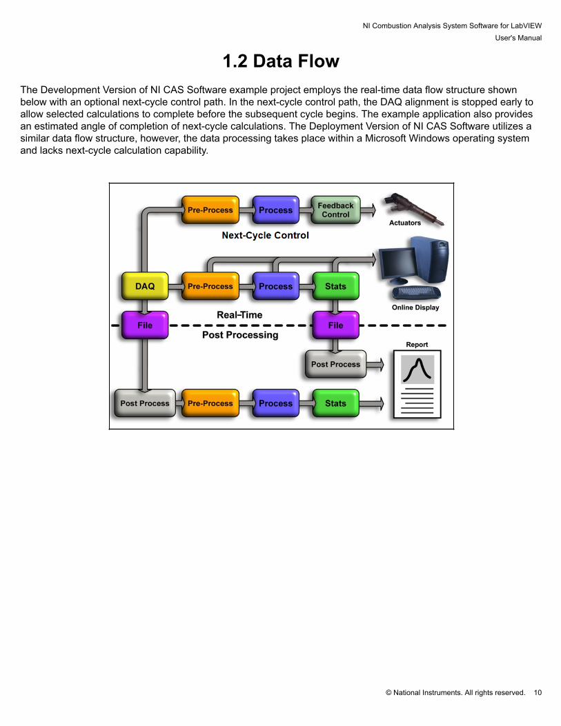
1.2 Data Flow The Development Version of NI CAS Software example project employs the real-time data flow structure shownbelow with an optional next-cycle control path. In the next-cycle control path, the DAQ alignment is stopped early toallow selected calculations to complete before the subsequent cycle begins. The example application also providesan estimated angle of completion of next-cycle calculations. The Deployment Version of NI CAS Software utilizes asimilar data flow structure, however, the data processing takes place within a Microsoft Windows operating systemand lacks next-cycle calculation capability.

NI Combustion Analysis System Software for LabVIEWUser's Manual
© National Instruments. All rights reserved. 11
2. Getting Started

NI Combustion Analysis System Software for LabVIEWUser's Manual
© National Instruments. All rights reserved. 12
2.1 Recommended System Requirements Note: System requirements will vary based on many factors including:
• Number of measurements• Maximum sample rate• Enabled real-time calculations
Development Version of NI CAS Software
Target System
Recommended Real-time SystemPXI Chassis: NI PXI-1050 PXI Chassis With Integrated SCXI--8 PXI/4 SCXI
SlotsController: NI PXI-8119 RT 2.3 GHz Quad-Core PXI Controller With
LabVIEW Real-Time80GB or Greater, 2.5 in SATA SSD
FPGA: NI PXI-7853R R Series Multifunction RIO With Virtex-5 LX85FPGA
C Series Hardware: • NI 9151 R Series Expansion Chassis for C Series I/O• NI 9411 6-Channel, 500ns, ±5 to 24 V Digital Input Module• NI SHC68-68-RDIO Digital Cable for R Series
S Series DAQ: 2 to 4 NI PXI-6123 16-Bit, 500 kS/s/ch, Simultaneous SamplingMultifunction DAQ
M Series DAQ NI PXI-6251 16-Bit, 1 MS/s (Multichannel), 1.25MS/s (1-Channel), 16 Analog Inputs
SCXI Modules: • 1 or 2 NI SCXI-1102 32-Channel Thermocouple/VoltageInput Module
• 1 or 2 NI SCXI-1102B 32-Channel Amplifier Module;200Hz Bandwidth
DAQ Accessories: • 2 to 4 NI BNC-2090A Shielded Rack-Mount BNCConnector Block
• 2 to 4 SH68-68-EP (for S Series modules)• 1 or 2 TC-2095 (for NI SCXI-1102)• 1 or 2 BNC-2095 (for NI SCXI-1102B)• 2 to 4 SH96-96 (for SCXI modules)
Host System
Recommended SystemCPU: 1.6 GHz Multi-Core or fasterOS: Microsoft Windows 7/8

NI Combustion Analysis System Software for LabVIEWUser's Manual
© National Instruments. All rights reserved. 13
RAM: 4 GB or moreHard Drive: 10 GB or more free spaceSoftware: • NI LabVIEW Professional Development System
• NI LabVIEW Real-Time Module• NI LabVIEW FPGA Module• NI-DAQmx• NI-RIO• NI LabVIEW FPGA Module Xilinx Tools• NI Software Calibration Management Toolkit for LabVIEW
Display resolution: ≥1920x1080

NI Combustion Analysis System Software for LabVIEWUser's Manual
© National Instruments. All rights reserved. 14
Deployment Version of NI CAS Software
Target System
Recommended cDAQ SystemcDAQ Chassis: • NI cDAQ-9139 NI CompactDAQ Stand-Alone Chassis,
Core i7 1.33 GHz, 8-slot• NI cDAQ-9174 NI CompactDAQ 4-Slot USB Chassis• NI cDAQ-9178 NI CompactDAQ 8-Slot USB Chassis• NI cDAQ-9184 NI CompactDAQ 4-Slot Ethernet Chassis• NI cDAQ-9188 NI CompactDAQ 8-Slot Ethernet Chassis
C Series Modules: See Supported C Series Modules Host System for USB and Ethernet cDAQ Targets
Recommended SystemCPU: 1.6 GHz Multi-core or fasterOS: Microsoft Windows 7/8RAM: 4 GB or moreHard Drive: 10 GB or more free spaceUSB: 2.0 (for USB devices)Software: • LabVIEW Runtime Engine
• NI-DAQmx• NI Software Calibration Management Toolkit for LabVIEW
Display resolution: ≥1920x1080
NI Combustion Analysis System Software for LabVIEWUser's Manual
© National Instruments. All rights reserved. 15
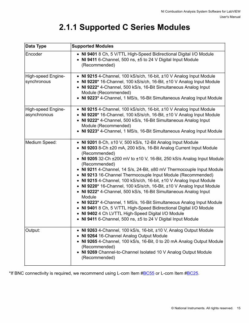
2.1.1 Supported C Series Modules
Data Type Supported Modules
Encoder • NI 9401 8 Ch, 5 V/TTL High-Speed Bidirectional Digital I/O Module• NI 9411 6-Channel, 500 ns, ±5 to 24 V Digital Input Module
(Recommended)
High-speed Engine-synchronous
• NI 9215 4-Channel, 100 kS/s/ch, 16-bit, ±10 V Analog Input Module• NI 9220* 16-Channel, 100 kS/s/ch, 16-Bit, ±10 V Analog Input Module• NI 9222* 4-Channel, 500 kS/s, 16-Bit Simultaneous Analog Input
Module (Recommended)• NI 9223* 4-Channel, 1 MS/s, 16-Bit Simultaneous Analog Input Module
High-speed Engine-asynchronous
• NI 9215 4-Channel, 100 kS/s/ch, 16-bit, ±10 V Analog Input Module• NI 9220* 16-Channel, 100 kS/s/ch, 16-Bit, ±10 V Analog Input Module• NI 9222* 4-Channel, 500 kS/s, 16-Bit Simultaneous Analog Input
Module (Recommended)• NI 9223* 4-Channel, 1 MS/s, 16-Bit Simultaneous Analog Input Module
Medium Speed: • NI 9201 8-Ch, ±10 V, 500 kS/s, 12-Bit Analog Input Module• NI 9203 8-Ch ±20 mA, 200 kS/s, 16-Bit Analog Current Input Module
(Recommended)• NI 9205 32-Ch ±200 mV to ±10 V, 16-Bit, 250 kS/s Analog Input Module
(Recommended)• NI 9211 4-Channel, 14 S/s, 24-Bit, ±80 mV Thermocouple Input Module• NI 9213 16-Channel Thermocouple Input Module (Recommended)• NI 9215 4-Channel, 100 kS/s/ch, 16-bit, ±10 V Analog Input Module• NI 9220* 16-Channel, 100 kS/s/ch, 16-Bit, ±10 V Analog Input Module• NI 9222* 4-Channel, 500 kS/s, 16-Bit Simultaneous Analog Input
Module• NI 9223* 4-Channel, 1 MS/s, 16-Bit Simultaneous Analog Input Module• NI 9401 8 Ch, 5 V/TTL High-Speed Bidirectional Digital I/O Module• NI 9402 4 Ch LVTTL High-Speed Digital I/O Module• NI 9411 6-Channel, 500 ns, ±5 to 24 V Digital Input Module
Output: • NI 9263 4-Channel, 100 kS/s, 16-bit, ±10 V, Analog Output Module• NI 9264 16-Channel Analog Output Module• NI 9265 4-Channel, 100 kS/s, 16-Bit, 0 to 20 mA Analog Output Module
(Recommended)• NI 9269 Channel-to-Channel Isolated 10 V Analog Output Module
(Recommended)
*If BNC connectivity is required, we recommend using L-com Item #BC55 or L-com Item #BC25.

NI Combustion Analysis System Software for LabVIEWUser's Manual
© National Instruments. All rights reserved. 16
2.2 Hardware Configuration
NI Combustion Analysis System Software for LabVIEWUser's Manual
© National Instruments. All rights reserved. 17
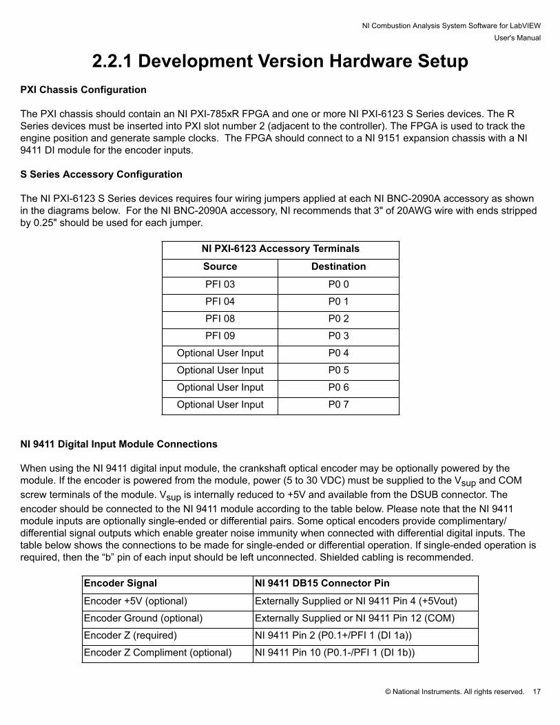
2.2.1 Development Version Hardware Setup PXI Chassis Configuration The PXI chassis should contain an NI PXI-785xR FPGA and one or more NI PXI-6123 S Series devices. The RSeries devices must be inserted into PXI slot number 2 (adjacent to the controller). The FPGA is used to track theengine position and generate sample clocks. The FPGA should connect to a NI 9151 expansion chassis with a NI9411 DI module for the encoder inputs. S Series Accessory Configuration The NI PXI-6123 S Series devices requires four wiring jumpers applied at each NI BNC-2090A accessory as shownin the diagrams below. For the NI BNC-2090A accessory, NI recommends that 3" of 20AWG wire with ends strippedby 0.25" should be used for each jumper.
NI PXI-6123 Accessory Terminals
Source Destination
PFI 03 P0 0
PFI 04 P0 1
PFI 08 P0 2
PFI 09 P0 3
Optional User Input P0 4
Optional User Input P0 5
Optional User Input P0 6
Optional User Input P0 7
NI 9411 Digital Input Module Connections When using the NI 9411 digital input module, the crankshaft optical encoder may be optionally powered by themodule. If the encoder is powered from the module, power (5 to 30 VDC) must be supplied to the Vsup and COMscrew terminals of the module. Vsup is internally reduced to +5V and available from the DSUB connector. Theencoder should be connected to the NI 9411 module according to the table below. Please note that the NI 9411module inputs are optionally single-ended or differential pairs. Some optical encoders provide complimentary/differential signal outputs which enable greater noise immunity when connected with differential digital inputs. Thetable below shows the connections to be made for single-ended or differential operation. If single-ended operation isrequired, then the “b” pin of each input should be left unconnected. Shielded cabling is recommended.
Encoder Signal NI 9411 DB15 Connector Pin
Encoder +5V (optional) Externally Supplied or NI 9411 Pin 4 (+5Vout)
Encoder Ground (optional) Externally Supplied or NI 9411 Pin 12 (COM)
Encoder Z (required) NI 9411 Pin 2 (P0.1+/PFI 1 (DI 1a))
Encoder Z Compliment (optional) NI 9411 Pin 10 (P0.1-/PFI 1 (DI 1b))

NI Combustion Analysis System Software for LabVIEWUser's Manual
© National Instruments. All rights reserved. 18
Encoder A (required) NI 9411 Pin 1 (P0.0+/PFI 0 (DI 0a))
Encoder A Compliment (optional) NI 9411 Pin 9 (P0.0-/PFI 0 (DI 0b))
Encoder B (optional) NI 9411 Pin 3 (P0.2+/PFI 2 (DI 2a))
Encoder B Compliment (optional) NI 9411 Pin 11 (P0.2-/PFI 2 (DI 2b))
Expected Encoder Signals The Deployment Version of NI CAS Software allows for a variety of encoders and triggering options by using theEngine Position Tracking (EPT) FPGA cores to synchronize the DAQ sampling. The FPGA block accepts only theencoder pattern. The encoder pattern consists of evenly spaced A and B pulses combined with a once per revolutionZ pulse. An additional signal can optionally be used to determine the phase of a 4-stroke engine. This can be any signal thathas a unique pattern for the complete engine cycle, e.g., a cam pattern, cylinder pressure, spark, injector or similar. The Development Version of NI CAS Software also has the ability to extrapolate low resolution encoder signals toincrease the sample resolution greater than the encoder resolution. Similarly, the encoder signal can be divided toreduce the sample resolution.
NI Combustion Analysis System Software for LabVIEWUser's Manual
© National Instruments. All rights reserved. 19
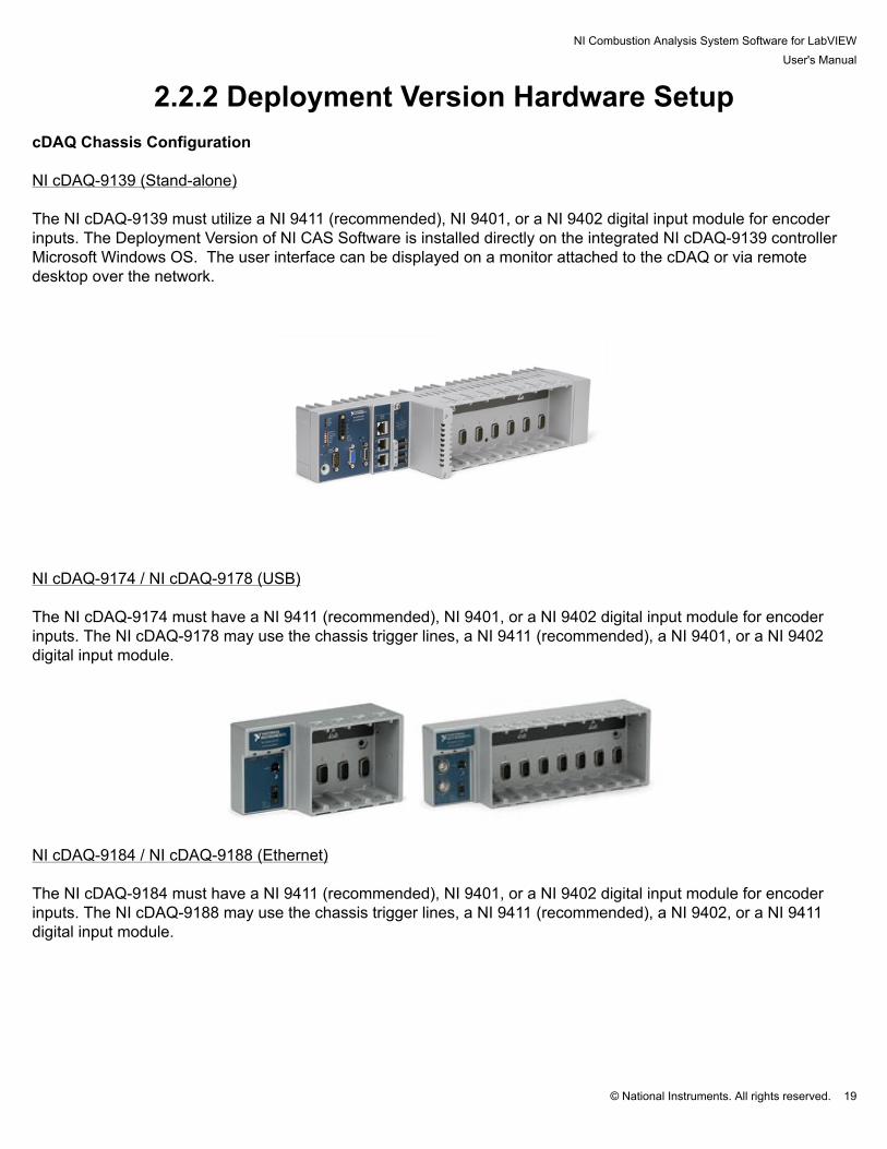
2.2.2 Deployment Version Hardware Setup cDAQ Chassis Configuration
NI cDAQ-9139 (Stand-alone) The NI cDAQ-9139 must utilize a NI 9411 (recommended), NI 9401, or a NI 9402 digital input module for encoderinputs. The Deployment Version of NI CAS Software is installed directly on the integrated NI cDAQ-9139 controllerMicrosoft Windows OS. The user interface can be displayed on a monitor attached to the cDAQ or via remotedesktop over the network.
NI cDAQ-9174 / NI cDAQ-9178 (USB)
The NI cDAQ-9174 must have a NI 9411 (recommended), NI 9401, or a NI 9402 digital input module for encoderinputs. The NI cDAQ-9178 may use the chassis trigger lines, a NI 9411 (recommended), a NI 9401, or a NI 9402digital input module.
NI cDAQ-9184 / NI cDAQ-9188 (Ethernet)
The NI cDAQ-9184 must have a NI 9411 (recommended), NI 9401, or a NI 9402 digital input module for encoderinputs. The NI cDAQ-9188 may use the chassis trigger lines, a NI 9411 (recommended), a NI 9402, or a NI 9411digital input module.

NI Combustion Analysis System Software for LabVIEWUser's Manual
© National Instruments. All rights reserved. 20
C Series Hardware The Deployment Version of NI CAS Software requires a 4-slot (or greater) USB, Ethernet, or stand-alone cDAQchassis, an NI 9411 digital input module, and one or more analog input modules. The compatible C Series I/Omodules are listed in the Support C Series Modules page. Connect and install the cDAQ hardware according the recommendations found at: http://www.ni.com/gettingstarted Encoder Connections NI 9411 Differential Digital Input Module (recommended) For optimum signal integrity, NI recommends using the NI 9411 Differential Digital Input Module connected to anoptical encoder supporting complimentary outputs. When using the NI 9411 digital input module, the crankshaft optical encoder may be optionally powered by themodule. If the encoder is powered from the module, power (5 to 30 VDC) must be supplied to the Vsup and COMscrew terminals of the module. Vsup is internally reduced to +5V and available from the DSUB connector. Theencoder should be connected to the NI 9411 module according to the table below. Please note that the NI 9411module inputs are optionally single-ended or differential pairs. Some optical encoders provide complimentary/differential signal outputs which enable greater noise immunity when connected with differential digital inputs. Thetable below shows the connections to be made for single-ended or differential operation. If single-ended operation isrequired, then the “b” pin of each input should be left unconnected. Shielded cabling is recommended.
Encoder Signal NI 9411 DB15 Connector PinEncoder +5V (optional) Externally Supplied or NI 9411 Pin 4 (+5Vout)Encoder Ground (optional) Externally Supplied or NI 9411 Pin 12 (COM)Encoder Z (required) NI 9411 Pin 2 (P0.1+/PFI 1 (DI 1a))Encoder Z Compliment(optional)
NI 9411 Pin 10 (P0.1-/PFI 1 (DI 1b))
Encoder A (required) NI 9411 Pin 1 (P0.0+/PFI 0 (DI 0a))Encoder A Compliment(optional)
NI 9411 Pin 9 (P0.0-/PFI 0 (DI 0b))

NI Combustion Analysis System Software for LabVIEWUser's Manual
© National Instruments. All rights reserved. 21
NI 9401 Digital Input Module When using the NI 9401 digital I/O module, the crankshaft optical encoder must be powered externally and aground reference from the encoder must be connected to a COM pin of the NI 9401 module. The encoder should beconnected to the NI-9401 module according to the table below. Shielded cabling is recommended.
Crankshaft optical encoder connections to the NI 9401 moduleEncoder Signal NI 9401 DB25 Connector Pin
Encoder Ground (required) NI 9401 Pin 1 (COM)
Encoder Z (required) NI 9401 Pin 16 (P0.1/PFI 1)
Encoder A (required) NI 9401 Pin 14 (P0.0/PFI 0) NI 9402 Digital Input Module When using the NI 9402 digital I/O module, the crankshaft optical encoder must be powered externally. The NI9402 should be used when BNC connectors are desired. The encoder should be connected to the NI 9402 moduleaccording to the table below.
Crankshaft optical encoder connections to the NI 9402 moduleEncoder Signal NI 9402 BNC
Encoder Z (required) NI 9402 BNC2 (P0.1/PFI 1)
Encoder A (required) NI 9402 BNC1 (P0.0/PFI 0)
NI cDAQ-9178 Chassis
When using the NI cDAQ-9178 chassis external triggers, the crankshaft optical encoder must be externally powered.The encoder should be connected to the NI cDAQ-9178 chassis according to the table below. Shielded cabling isrecommended.
Crankshaft optical encoder connections to the cDAQ-9178 chassisEncoder Signal NI cDAQ-9178 Chassis BNC Connector
Encoder Z (required) cDAQ-9178 Trig 1
Encoder A (required) cDAQ-9178 Trig 0 Analog Input Module Connections The analog instrumentation signals should be connected to the NI 9215, NI 9222, or NI 9223 analog inputs. TheBNC version of the NI 9215 is recommended for ease of connection. Shielded BNC cables are recommended. Configuring cDAQ Chassis with NI Measurement and Automation Explorer NI Measurements and Automation Explorer (MAX) should be used to discover or change the name of the DAQdevice and its physical channels. The names of the device and physical channels will be used on the measurementconfiguration tab of the user interface.

NI Combustion Analysis System Software for LabVIEWUser's Manual
© National Instruments. All rights reserved. 22
Ethernet cDAQ devices must be registered and reserved in MAX before they can be used with the DeploymentVersion of NI CAS Software. To add a cDAQ chassis to a system, right click on "My System > Devices and Interfaces> Network Devices" and select "Find Network NI-DAQmx Device". To reserve the cDAQ chassis on a system, rightclick on the discovered cDAQ chassis and select "Reserve Chassis". When using the DAQ device with the Deployment Version of NI CAS Software, only the terminals described aboveshould be used. In order to take full advantage of certain hardware features, the Deployment Version of NI CASSoftware makes programmatic internal connections. Connecting signals to other terminals or running other programswhich interact with the DAQ device may cause unexpected behavior.

NI Combustion Analysis System Software for LabVIEWUser's Manual
© National Instruments. All rights reserved. 23
2.3 Software ConfigurationFor more information on the NI Combustion Analysis System Software for NI LabVIEW, please visit http://www.ni.com/powertrain-controls/. To download the NI Combustion Analysis System Software for LabVIEW, visit http://www.ni.com/info andenter the Info Code "CASSoftware". After installing NI CAS Software, it will run for a 7 day full evaluation period. Any time during or after theevaluation period, NI CAS Software may be activated using the NI License Manager found in the startmenu.

NI Combustion Analysis System Software for LabVIEWUser's Manual
© National Instruments. All rights reserved. 24
2.3.1 Activating Your SoftwareActivating Your Software
This section describes how to use the NI Activation Wizard to activate your software. How Do I Activate My Software?Use the NI Activation Wizard to obtain an activation code for your software. You can launch the NI Activation Wizardtwo ways:
• Launch the product and choose to activate your software from the list of options presented.• Launch NI License Manager by selecting Start»All Programs»National Instruments»NI LicenseManager. Click the Activate button in the toolbar.
Notes
• If your software is a part of a Volume License Agreement (VLA), contact your VLA administratorfor installation and activation instructions.
• NI software for Mac OS X and Linux operating systems does not require activation.
What is Activation? Activation is the process of obtaining an activation code to enable your software to run on your computer. Anactivation code is an alphanumeric string that verifies the software, version, and computer ID to enable features onyour computer. Activation codes are unique and are valid on only one computer. What is the NI Activation Wizard? The NI Activation Wizard is a part of NI License Manager that steps you through the process of enabling software torun on your machine. What Information Do I Need to Activate? You need your product serial number, user name, and organization. The NI Activation Wizard determines the rest ofthe information. Certain activation methods may require additional information for delivery. This information is usedonly to activate your product. Complete disclosure of the National Instruments software licensing information privacypolicy is available at ni.com/activate/privacy. If you optionally choose to register your software, your information isprotected under the National Instruments privacy policy, available at ni.com/privacy. How Do I Find My Product Serial Number? Your serial number uniquely identifies your purchase of NI software. You can find your serial number on theCertificate of Ownership included in your software kit. If your software kit does not include a Certificate of Ownership,you can find your serial number on the product packing slip or on the shipping label. If you have installed a previous version using your serial number, you can find the serial number by selecting theHelp»About menu item within the application or by selecting your product within NI License Manager (Start»AllPrograms»National Instruments»NI License Manager). You can also contact your local National Instrumentsbranch.

NI Combustion Analysis System Software for LabVIEWUser's Manual
© National Instruments. All rights reserved. 25
What is a Computer ID? The computer ID contains unique information about your computer. National Instruments requires this informationto enable your software. You can find your computer ID through the NI Activation Wizard or by using NI LicenseManager, as follows:
1. Launch NI License Manager by selecting Start»All Programs»National Instruments»NI LicenseManager.2. Click the Display Computer Information button in the toolbar.
For more information about product activation and licensing, refer to ni.com/activate. How Can I Evaluate NI Software?You can install and run most NI application software in evaluation mode. This mode lets you use a product withcertain limitations, such as reduced functionality or limited execution time. Refer to your product documentation forspecific information on the product’s evaluation mode. Moving Software After Activation To transfer your software to another computer, install and activate it on the second computer. You are not prohibitedfrom transferring your software from one computer to another and you do not need to contact or inform NI of thetransfer. Because activation codes are unique to each computer, you will need a new activation code. Refer to HowDo I Activate My Software? to acquire a new activation code and reactivate your software. Deactivating a Product To deactivate a product and return the product to the state it was in before you activated it, right- click the product inthe NI License Manager tree and select Deactivate. If the product was in evaluation mode before youactivated it, theproperties of the evaluation mode may not be restored. Using Microsoft Windows Guest AccountsNI License Manager does not support Microsoft Windows Guest accounts. You must log in to a non-Guest accountto run licensed NI application software.

NI Combustion Analysis System Software for LabVIEWUser's Manual
© National Instruments. All rights reserved. 26
2.3.2 MAX Hardware Configuration

NI Combustion Analysis System Software for LabVIEWUser's Manual
© National Instruments. All rights reserved. 27
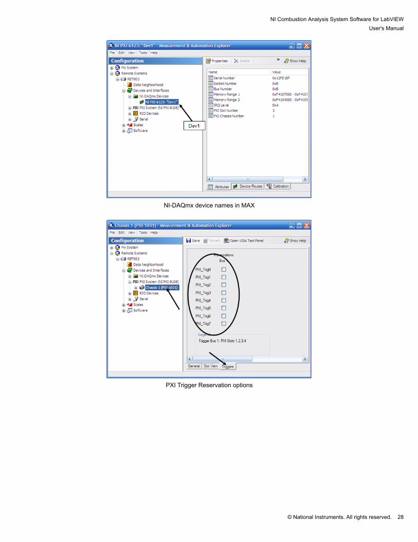
2.2.2.1 Development Version MAX Hardware Configuration Using NI Measurement and Automation Explorer (MAX), configure the PXI chassis and real-time controller. Setthe IP address to a desired static value. Install the current versions of NI LabVIEW Real-Time Module and theNI-DAQmx Drivers along with any other desired software. Finally, make sure the PXI system controller and PXIchassis are defined correctly in MAX, as shown in figures below MAX can also change the aliases (names) andbasic configurations of the DAQ devices if desired. The user must take note of a few configuration settings in MAX in order to work with NI CAS Software. The DAQdevice aliases, as shown in the figures below, are used to identify the physical channels in the NI CAS Softwaremeasurement setup. The DAQ device can be renamed by right clicking on the device and selecting the renameoption. Finally, the user must confirm that the PXI Trigger Lines are not reserved for other functions in MAX, asshown in the figures below. They are automatically reserved as a part of the channel configuration within the NI CASSoftware.
PXI Chassis Identification configuration in MAX
NI Combustion Analysis System Software for LabVIEWUser's Manual
© National Instruments. All rights reserved. 28
NI-DAQmx device names in MAX
PXI Trigger Reservation options

NI Combustion Analysis System Software for LabVIEWUser's Manual
© National Instruments. All rights reserved. 29
2.2.2.2 Deployment Version MAX Hardware Configuration The user must take note of a few configuration settings in NI Measurement and Automation Explorer (MAX) inorder to work with the NI CAS Software. The DAQ device aliases, as shown below, are used to identify the physicalchannels in the NI CAS Software measurement setup. The DAQ device can be renamed by right clicking on thedevice and selecting the rename option.

NI Combustion Analysis System Software for LabVIEWUser's Manual
© National Instruments. All rights reserved. 30
2.3.3 Development Version ExampleProject and System Integration
The Development Version of NI CAS Software can be run as a stand alone application using the NI CAS Softwareexample application. The following steps are required to run the NI CAS Software example.
1. Open the CAS example project. From LabVIEW, select Help > Find Examples. Search for "CombustionAnalysis"
2. Update the PXI target IP address for the user's PXI target. Right click on the PXI icon in the project and select"Properties"
3. Confirm or update the expansion chassis, C Series modules, and FPGA I/O in "CAS FPGA.vi" to match theuser's hardware.
4. Open and compile "CAS FPGA.vi" in the FPGA target.5. Open "CAS Target.vi" in the PXI target.6. Run "SCM Init" by double clicking on the icon on the block diagram of "CAS Target.vi". It is the right most block
diagram item.7. Run "CAS Target.vi".8. Launch NI SCM Console and point it to the PXI target IP address, "CAS Host.vi", and "CAS Host.par". The host
files are located with the project in the examples folder. For more information on the SCM Console, please seethe SCM user's manual.
Integrating Development Version Into An Engine Control Application
The Development Version of NI CAS Software can run as a stand alone application or as part of a larger project. Asingle PXI chassis can run both an engine controller and combustion analysis. Integrating the two systems into asingle platform allows lowered equipment costs in addition to providing closed loop feedback to the engine controller.The following steps are required to integrate the Development Version of NI CAS Software into an engine controlapplication. First, open the CAS example project. From LabVIEW, select Help > Find Examples. Search for "CAS". FPGA
1. Open "CAS FPGA.vi" under the CAS PXI\FPGA target.2. Copy the single cycle loop from the CAS PXI\FPGA to the engine control FPGA.3. Copy "CAS Data" and "CAS Encoder Debug" FIFOs from the CAS PXI\FPGA target to the engine control FPGA
target.4. Copy the PXI folder containing TRIG0-7 from the CAS PXI\FPGA target to the engine control FPGA target.5. Make sure the encoder signals are connected to the appropriate sources.6. Compile the engine control FPGA VI.
Real-Time
1. Open "CAS Target.vi" under the PXI target.2. Copy the contents of "CAS Target.vi" into your engine control target VI.3. Remove the SCM Init VI and FPGA Open Reference function copied from the CAS example.4. Connect the the SCM Init VI and FPGA Open Reference function from your engine control application to the
copied CAS code.

NI Combustion Analysis System Software for LabVIEWUser's Manual
© National Instruments. All rights reserved. 31
Note: The FPGA reference must be set to "Dynamic mode"

NI Combustion Analysis System Software for LabVIEWUser's Manual
© National Instruments. All rights reserved. 32
2.4 Performance
NI Combustion Analysis System Software for LabVIEWUser's Manual
© National Instruments. All rights reserved. 33
2.4.1 Development Version Performance Overview The performance of the system depends on many factors including:
• PXI Controller Speed, Ram, & OS (Microsoft Windows or Real-Time)• DAQ Hardware Limitations (Sampling Rate, Response Times)• Engine Speed• Cylinder/Measurement Count• Asynchronous Sampling Rate• Medium Speed Data (Number of Channels and Sample Rate)• FPGA Data (Number of Channels and Sample Rate)• Encoder Resolution• Calculation Parameters• HDD Throughput• User Calculations

NI Combustion Analysis System Software for LabVIEWUser's Manual
© National Instruments. All rights reserved. 34
2.4.1.1 S Series Hardware One of the key items limiting the maximum engine speed is the DAQ hardware. There are two cases where theDAQ hardware may limit the maximum engine speed. The first is the case where the DAQ equipment has a largesample rate but the encoder resolution is high. For example, a 500kS/s/ch DAQ device is limited to ~8333RPMwith a 3600ppr encoder. The second case is where the DAQ hardware has a small sample rate. For example, amultiplexed sampling device at 1MS/s divided among 16 channels has a 62.5kS/s/ch sampling rate.
The data above was calculated using the following equation:
Where:
MS = Maximum Speed [RPM]SR = Sample Rate [kS/s/ch]ER = Encoder Resolution [ppr]

NI Combustion Analysis System Software for LabVIEWUser's Manual
© National Instruments. All rights reserved. 35
2.4.1.2 HDD Streaming data to the disk requires that the speed of the hard drive is fast enough to keep up with the data waitingto write to it. Disk access is typically between 10MB/s and 70MB/s. However, due to seek times and writing headerinformation, the actual speed at which the system can stream data to disk may be slower. The throughput of aspecific HDD is dependent on many factors including the type of hard drive and the system that it is installed in. TheNI CAS Software will buffer data in the RAM if the disk is not fast enough to stream all the data to disk. However, thebuffers have limited space and cannot sustain continuous streaming if the disk is not fast enough.
The data above was calculated using the following equation:
Where:
MS = Maximum Speed [RPM]SR = Sample per Rotation []DS = Disk Speed [MB/s]

NI Combustion Analysis System Software for LabVIEWUser's Manual
© National Instruments. All rights reserved. 36
2.4.2 Deployment Version Performance Overview The performance of the system depends on many factors including:
• CPU speed• RAM size and speed• Hard drive speed• Operating system and additional running applications• DAQ hardware limitations (sampling rate, response times)• Medium Speed Data (Number of Channels and Sample Rate)• Engine speed• Encoder resolution• Cylinder and measurement channel count• Calculation configurations

NI Combustion Analysis System Software for LabVIEWUser's Manual
© National Instruments. All rights reserved. 37
2.4.2.1 cDAQ Hardware The figure below shows the cDAQ hardware limitations. The cDAQ system uses simultaneous sampling device.Therefore, the DAQ hardware limitations are constant for any number of cylinders.
The following formula can be used to estimate the performance of a simultaneous DAQ hardware device.
Where:
Speed = Maximum Engine Speed [rpm]MSR = Maximum Sample Rate of DAQ device (kS/s)ER = Encoder Resolution [ppr]

NI Combustion Analysis System Software for LabVIEWUser's Manual
© National Instruments. All rights reserved. 38
2.4.2.2 NI cDAQ-1939 Benchmark The NI cDAQ-1939 was tested under a variety of conditions in order to demonstrate the capabilities of the systemwhile running. Each test condition was evaluated on the maximum engine speed where the system could calculateall the results without loosing data for the real-time calculation and where the system could no longer write allincoming data to disk. The maximum speed of the test engine was 8000 RPM. Therefore, the test results showing an8000 RPM limit will probably be able to reach higher engine speeds.
NI cDAQ-1939
Cylinder Count 4 4 4 4 4 4
Encoder Resolution [ppr] 360 360 1800 1800 3600 3600
Strokes 4 4 4 4 4 4
Manifold Pegging x x x x x x
Mean Effective Pressure x x x x x x
Single Zone Heat Release x x x x x x
Knock Sensors 100 kS/s 0 2 0 2 0 2
Medium Speed Channels 10 S/s 0 20 0 20 0 20
Max Speed RT Processing [RPM] 8000 8000 8000 8000 5500 5000
Max Raw File Speed [RPM] 8000 8000* 8000 8000* 8000 6000*
NI cDAQ-1939
Cylinder Count 8 8 8 8 8 8
Encoder Resolution [ppr] 360 360 1800 1800 3600 3600
Strokes 4 4 4 4 4 4
Manifold Pegging x x x x x x
Mean Effective Pressure x x x x x x
Single Zone Heat Release x x x x x x
Knock Sensors 100 kS/s 0 4 0 4 0 4
Medium Speed Channels 10 S/s 0 20 0 20 0 20
Max Speed RT Processing [RPM] 8000 8000 5500 4000 3000 2500
Max Raw File Speed [RPM] 8000 8000* 8000 8000* 6000 6000**Performance Optimization Settings Adjusted

NI Combustion Analysis System Software for LabVIEWUser's Manual
© National Instruments. All rights reserved. 39
3. NI CAS Software Interface
The NI CAS Software Host VI is the top level VI. It contains links to all of the NI CAS Software built in screens andprovides the user with a starting place. This host always remains on top of other NI CAS Software hosts.
Deployment Development
1. Information and controls that are always available. The user can switch between the setup and running modes,open this help documentation or see if any error conditions exist. There may also be menu items available forsaving and loading calibrations and other useful functions.
2. Selection of different configurations and results groups.

NI Combustion Analysis System Software for LabVIEWUser's Manual
© National Instruments. All rights reserved. 40
3. SubHost list containing all the available NI CAS Software sub-hosts. Double clicking a name opens it if it isclosed (normal) or closes it if open (bold). A single click on an open (bold) name brings it to the front.

NI Combustion Analysis System Software for LabVIEWUser's Manual
© National Instruments. All rights reserved. 41
3.1 Offline

NI Combustion Analysis System Software for LabVIEWUser's Manual
© National Instruments. All rights reserved. 42
3.1.1 General Setup

NI Combustion Analysis System Software for LabVIEWUser's Manual
© National Instruments. All rights reserved. 43
3.1.1.1 Project Setup The project setup options must be configured in the offline mode. Information entered here will help identifycalibration files once loaded. Internal software simulation is also enabled in this window.
Engine Specifies the name or description of the engine.Operator Specifies the engine operator.Project Specifies the current test project.Simulation Enables a simulation that doesn't require hardware.

NI Combustion Analysis System Software for LabVIEWUser's Manual
© National Instruments. All rights reserved. 44
3.1.1.2 Engine Geometry Setup The engine geometry setup must be configured in the offline mode. Information entered should be specific to theengine and test setup as it affects all of the calculations results.
Bore Specifies the cylinder bore.Clearance Volume Specifies the clearance volume of the cylinder. [Compression Ratio = (Displacement
Volume + Clearance Volume) / Clearance Volume]Compression Ratio Indicates the calculated compression ratio. [Compression Ratio = (Displacement
Volume + Clearance Volume) / Clearance Volume]Connecting Rod Length Specifies the connecting rod length.Crown Area Specifies the piston crown surface area relative to the bore areaCylinder Count Defines the number of cylinders in the engine.Cylinder TDC Defines the cylinder Top Dead Center offsets relative to the absolute encoder offset.
NI Combustion Analysis System Software for LabVIEWUser's Manual
© National Instruments. All rights reserved. 45
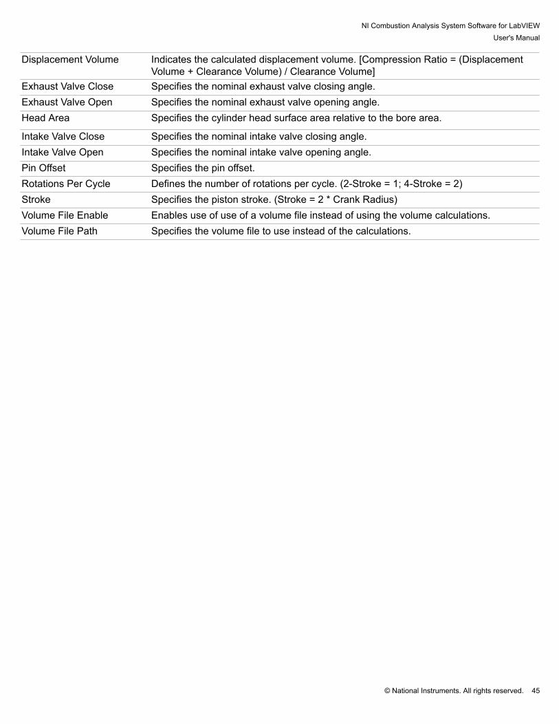
Displacement Volume Indicates the calculated displacement volume. [Compression Ratio = (DisplacementVolume + Clearance Volume) / Clearance Volume]
Exhaust Valve Close Specifies the nominal exhaust valve closing angle.Exhaust Valve Open Specifies the nominal exhaust valve opening angle.Head Area Specifies the cylinder head surface area relative to the bore area.
Intake Valve Close Specifies the nominal intake valve closing angle.Intake Valve Open Specifies the nominal intake valve opening angle.Pin Offset Specifies the pin offset.Rotations Per Cycle Defines the number of rotations per cycle. (2-Stroke = 1; 4-Stroke = 2)Stroke Specifies the piston stroke. (Stroke = 2 * Crank Radius)Volume File Enable Enables use of use of a volume file instead of using the volume calculations.Volume File Path Specifies the volume file to use instead of the calculations.

NI Combustion Analysis System Software for LabVIEWUser's Manual
© National Instruments. All rights reserved. 46
3.1.1.3 Encoder Setup The encoder setup must be configured in the offline mode. Information entered should be specific to the engine andtest setup as it affects all of the calculations results.
Deployment Development
Actual TDC Offset Indicates the actual top dead center offset used by the engine position tracking
system.Check Encoder Updates the encoder debug scope. (Note: Encoder must rotate at least 4 times for
the scope to update once the button is pressed)Cycle Resolution Indicates the calculated cycle resolution.Digital Filter Defines the digital glitch filter used by the engine position tracking system.

NI Combustion Analysis System Software for LabVIEWUser's Manual
© National Instruments. All rights reserved. 47
Encoder Debug LED Indicates whether the 'Measured Sample Resolution' and 'Measure Cycle Resolution'values match the 'Sample Resolution' and 'Cycle Resolution' values, respectively.
Encoder Divide Specifies the level to divide the extrapolated resolution by in order to determine thefinal sample resolution (Not all combinations of encoder resolution, extrapolationlevel, and encoder divide are valid.)
Encoder Setup Error Indicates an error in the engine position tracking configuration.Encoder Extrap Level Specifies the level of encoder extrapolation used in the engine position tracking
system. (2 valid)Encoder Resolution Specifies the encoder resolution as it is seen by the engine position tracking.Encoder Setup Determines which encoder events are used by the engine position tracking system.EPT Sim Enable Enables EPT simulation of the engine encoder signals for offline testing.Max Speed Specifies the maximum speed of the engine.Measured SampleResolution
Displays the number of edges counted for one encoder rotation.
Measured Cycle Resolution Displays the number of edges counted for one engine cycle.Disable FPGA Specifies if the system is configured for acquiring data without an FPGA engine
position tracking system.Phase Determines the method of preprocessing the encoder signal to pass only a single
index pulse per cycle to the engine position tracking system.Random Z Phase Defines which cycle to use when using a random z.Sample Resolution Indicates the calculated sample resolution based on the encoder settings.TDC Offset Specifies the global TDC offset. It is commonly used to easily adjust for changes in
the encoder without needing to change each cylinder TDC.cDAQ DIO Module Specifies the encoder index signal name when using the Deployment Version of NI
CAS Software and a cDAQ chassis.

NI Combustion Analysis System Software for LabVIEWUser's Manual
© National Instruments. All rights reserved. 48
3.1.1.4 Calculations In setup mode, the user can enable or disable different groups of calculations to perform real-time calculations onthe target. Each group of calculations has its own settings and results. Enabling calculation groups will increase theprocessor usage depending on the complexity of the calculations. Note: Some calculations require results from another calculation group in order to work, i.e., heat release modelsincluding heat transfer simulation require the 'Gas Temp' calculation to be enabled.

NI Combustion Analysis System Software for LabVIEWUser's Manual
© National Instruments. All rights reserved. 49
3.1.1.5 Next-Cycle Calculations In setup mode, the user can enable or disable different groups of calculations to perform next-cycle calculations onthe target. Each group of calculations has its own settings and results. Enabling calculation groups will increase theprocessor usage depending on the complexity of the calculations and increase the time required to provide next-cycle results. Note: Some calculations require results from another calculation group in order to work, i.e., heat release modelsincluding heat transfer simulation require the 'Gas Temp' calculation to be enabled.
*Only available with the Development License.

NI Combustion Analysis System Software for LabVIEWUser's Manual
© National Instruments. All rights reserved. 50
3.1.1.6 System Optimization The performance dialog allow users to tune some of the NI CAS Software behavior with their system and setup. Thecurrent settings should work well for most configurations.
TargetRolling Stats Size Configures the rolling statistics buffers used in trends and tables.Buffer Size Determines the desired length of the alignment and raw file buffers.Pre-Triggered Size Determines the number of cycles the raw system will maintain before a start file event.Trigger Size Determines the number of cycles to save to a raw file at a time to improve disk
performance.Waveform Refresh Rate Configures the maximum update rate of plot data.Statistics Refresh Rate Configures the maximum update rate of statistical data. HostStart Delay Delays the start of Host VI execution to allow initialization.Plot Period Determines the maximum update rate of plot.Table Period Determines the maximum update rate of tables.Trend Period Determines the maximum update rate of trends.Knock Period Determines the maximum update rate of the knock configuration display.

NI Combustion Analysis System Software for LabVIEWUser's Manual
© National Instruments. All rights reserved. 51
3.1.2 IO Hardware Setup

NI Combustion Analysis System Software for LabVIEWUser's Manual
© National Instruments. All rights reserved. 52
3.1.2.1 Sample Rates Setup The sample rates setup must be configured in the offline mode. Information entered should be specific to the dataacquisition hardware used as invalid inputs will cause DAQ errors.
Async Rate Specifies the sample rate of the asynchronous data.Max Sync Rate Specifies the maximum sample rate of the synchronous measurement DAQ device.Medium Speed Rate Specifies the sample rate of the medium speed DAQ.

NI Combustion Analysis System Software for LabVIEWUser's Manual
© National Instruments. All rights reserved. 53
3.1.2.2 Sync Analog Channels Setup The engine synchronous measurement setup is used to define all the physical channels. These measurements aresampled at even crank angle increments with respect to the engine.
1. Summary of all defined measurements.2. Controls for manipulating the list of measurements.3. Detailed setup of the selected measurement.
Cylinder Cylinders associated with each measurement in a bitfield.Disable Disables data acquisition and calculations associated with each measurement.Filter Filter resource number associated with each measurement. (0 = No Filter)Gain Gain associated with each measurement when using the gain only or gain and offset scaling
methods.Max Maximum channel voltage range associated with each measurement.Min Minimum channel voltage range associated with each measurement.Name Name or description associated with each measurement.Offset Offset associated with each measurement when using the gain and offset scaling method.Physical Channel Physical channel associated with each measurement.PolynomialCoefficients
Polynomial Coefficients associated with each measurement when using the polynomialscaling method.
Scaling Scaling method associated with each measurement.Table X Table X array associated with each measurement when using the table scaling method.Table Y Table Y array associated with each measurement when using the table scaling method.

NI Combustion Analysis System Software for LabVIEWUser's Manual
© National Instruments. All rights reserved. 54
Terminal Configuration Terminal Configuration array associated with each measurement.Type Measurement Type associated with each measurement.Units Units associated with each measurement.
NI Combustion Analysis System Software for LabVIEWUser's Manual
© National Instruments. All rights reserved. 55
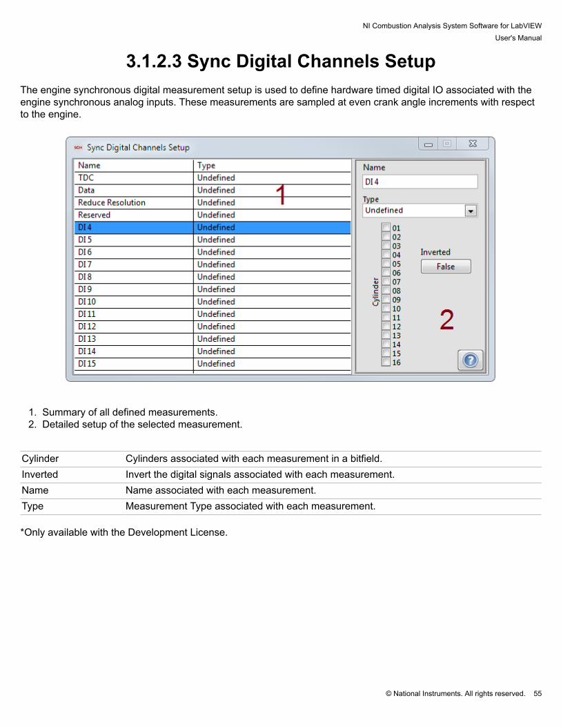
3.1.2.3 Sync Digital Channels Setup The engine synchronous digital measurement setup is used to define hardware timed digital IO associated with theengine synchronous analog inputs. These measurements are sampled at even crank angle increments with respectto the engine.
1. Summary of all defined measurements.2. Detailed setup of the selected measurement.
Cylinder Cylinders associated with each measurement in a bitfield.Inverted Invert the digital signals associated with each measurement.Name Name associated with each measurement.Type Measurement Type associated with each measurement. *Only available with the Development License.

NI Combustion Analysis System Software for LabVIEWUser's Manual
© National Instruments. All rights reserved. 56
3.1.2.4 Async Analog Channels Setup The time-based asynchronous measurement setup is used to define all the physical channels. These measurementsare sampled at a fixed frequency.
1. Summary of all defined measurements.2. Controls for manipulating the list of measurements.3. Detailed setup of the selected measurement.
Cylinder Cylinders associated with each measurement in a bitfield.Disable Disables data acquisition and calculations associated with each measurement.Filter Filter resource number associated with each measurement. (0 = No Filter)Gain Gain associated with each measurement when using the gain only or gain and offset scaling
methods.Max Maximum channel voltage range associated with each measurement.Min Minimum channel voltage range associated with each measurement.Name Name or description associated with each measurement.Offset Offset associated with each measurement when using the gain and offset scaling method.Physical Channel Physical channel associated with each measurement.PolynomialCoefficients
Polynomial Coefficients associated with each measurement when using the polynomialscaling method.
Scaling Scaling method associated with each measurement.Table X Table X array associated with each measurement when using the table scaling method.Table Y Table Y array associated with each measurement when using the table scaling method.

NI Combustion Analysis System Software for LabVIEWUser's Manual
© National Instruments. All rights reserved. 57
Terminal Configuration Terminal Configuration array associated with each measurement.Type Measurement Type associated with each measurement.Units Units associated with each measurement.

NI Combustion Analysis System Software for LabVIEWUser's Manual
© National Instruments. All rights reserved. 58
3.1.2.5 Async Digital Channels Setup The time-based asynchronous digital measurement setup is used to define hardware timed digital IO associated withthe asynchronous analog inputs. These measurements are sampled at a fixed frequency.
1. Summary of all defined measurements.2. Detailed setup of the selected measurement.
Cylinder Cylinders associated with each measurement in a bitfield.Inverted Invert the digital signals associated with each measurement.Name Name associated with each measurement.Type Measurement Type associated with each measurement. *Only available with the Development License.

NI Combustion Analysis System Software for LabVIEWUser's Manual
© National Instruments. All rights reserved. 59
3.1.2.6 Medium Speed Channels Setup The time-based medium speed measurement setup is used to define all the physical channels. Medium speed areintended for sampling test cell and other auxiliary signals. These measurements are sampled at a fixed frequency.
1. Summary of all defined measurements.2. Controls for manipulating the list of measurements. Enable/Disable engine cycle averages and statistic
calculations.3. Detailed setup of the selected measurement.
CJC Channel Cold junction compensation channel associated with each measurement when using a
channel cold junction compensation source.CJC Source Cold junction compensation source associated with each measurement.CJC Value Cold junction compensation value associated with each measurement when using a constant
cold junction compensation source.Disable Disables data acquisition and calculations associated with each measurement.Filter Cutoff Knock Threshold for Each CylinderGain Gain associated with each measurement.Max Maximum voltage, current, or temperature associated with each measurement.Min Minimum voltage, current, or temperature associated with each measurement.Name Name or description associated with each measurement.Offset Offset associated with each measurement.Physical Channel Physical channel associated with each measurement.

NI Combustion Analysis System Software for LabVIEWUser's Manual
© National Instruments. All rights reserved. 60
Save Trigger Enables the channel to be used to trigger the start of a file save. Each index is associatedwith each measurement.
Scaling Scaling method associated with each measurement.TerminalConfiguration
Terminal configuration associated with each measurement.
Thermocouple Type Thermocouple type associated with each measurement.Units Units associated with each measurement.

NI Combustion Analysis System Software for LabVIEWUser's Manual
© National Instruments. All rights reserved. 61
3.1.2.7 FPGA Stream Setup The FPGA setup is used to define data streamed from the FPGA. The measurements are defined in the FPGA whenusing an FPGA with the Development Version of NI CAS Software. Defining them in the FPGA setup allows theDevelopment Version of NI CAS Software to calculate cycle averages and statistics for the display and summaryfiles.
1. Summary of all defined measurements.2. Controls for manipulating the list of measurements. Enable/Disable engine cycle averages and statistic
calculations.3. Detailed setup of the selected measurement.
Gain Gain associated with each measurement.ID ID associated with each FPGA measurement.Name Name or description associated with each measurement.Offset Offset associated with each measurement.Units Units associated with each measurement. *Only available with the Development Version of NI CAS Software

NI Combustion Analysis System Software for LabVIEWUser's Manual
© National Instruments. All rights reserved. 62
3.1.2.8 Analog Output Channels Setup The analog output setup defines analog outputs channels. These channels link to calculated results in NI CASSoftware based on name. The recent names contain a list of available results from the last time the system ran.
1. Summary of all defined outputs.2. Controls for manipulating the list of outputs.3. Detailed setup of the selected outputs.
AO Type Analog output type associate with the measurement.Cylinder Cylinder associated with each measurement.Disable Disables data acquisition and calculations associated with each measurement.Gain Gain associated with each measurement.Max Maximum voltage range associate with the measurement.Min Minimum voltage range associate with the measurement.Name Name or description associated with each measurement.Offset Offset associated with each measurement.Physical Channel Physical channel associated with each measurement.Type Measurement Type associated with each measurement.

NI Combustion Analysis System Software for LabVIEWUser's Manual
© National Instruments. All rights reserved. 63
3.2 Online

NI Combustion Analysis System Software for LabVIEWUser's Manual
© National Instruments. All rights reserved. 64
3.2.1 Settings
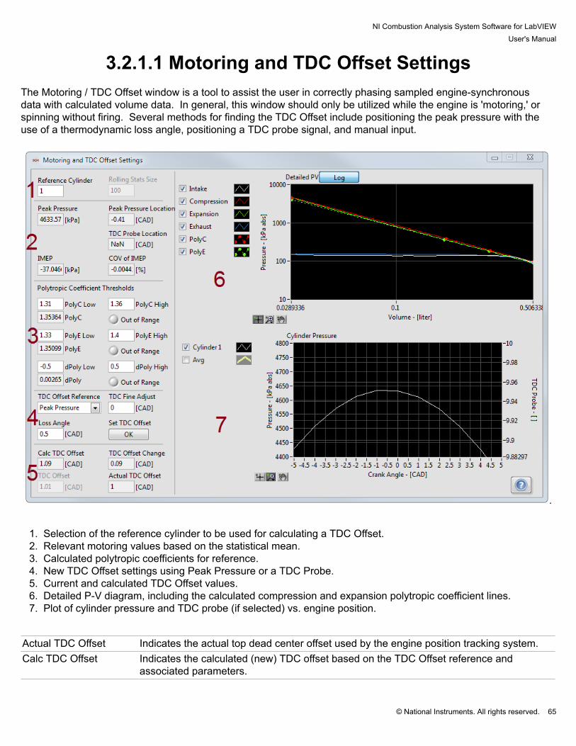
NI Combustion Analysis System Software for LabVIEWUser's Manual
© National Instruments. All rights reserved. 65
3.2.1.1 Motoring and TDC Offset Settings The Motoring / TDC Offset window is a tool to assist the user in correctly phasing sampled engine-synchronousdata with calculated volume data. In general, this window should only be utilized while the engine is 'motoring,' orspinning without firing. Several methods for finding the TDC Offset include positioning the peak pressure with theuse of a thermodynamic loss angle, positioning a TDC probe signal, and manual input.
.
1. Selection of the reference cylinder to be used for calculating a TDC Offset.2. Relevant motoring values based on the statistical mean.3. Calculated polytropic coefficients for reference.4. New TDC Offset settings using Peak Pressure or a TDC Probe.5. Current and calculated TDC Offset values.6. Detailed P-V diagram, including the calculated compression and expansion polytropic coefficient lines.7. Plot of cylinder pressure and TDC probe (if selected) vs. engine position.
Actual TDC Offset Indicates the actual top dead center offset used by the engine position tracking system.Calc TDC Offset Indicates the calculated (new) TDC offset based on the TDC Offset reference and
associated parameters.
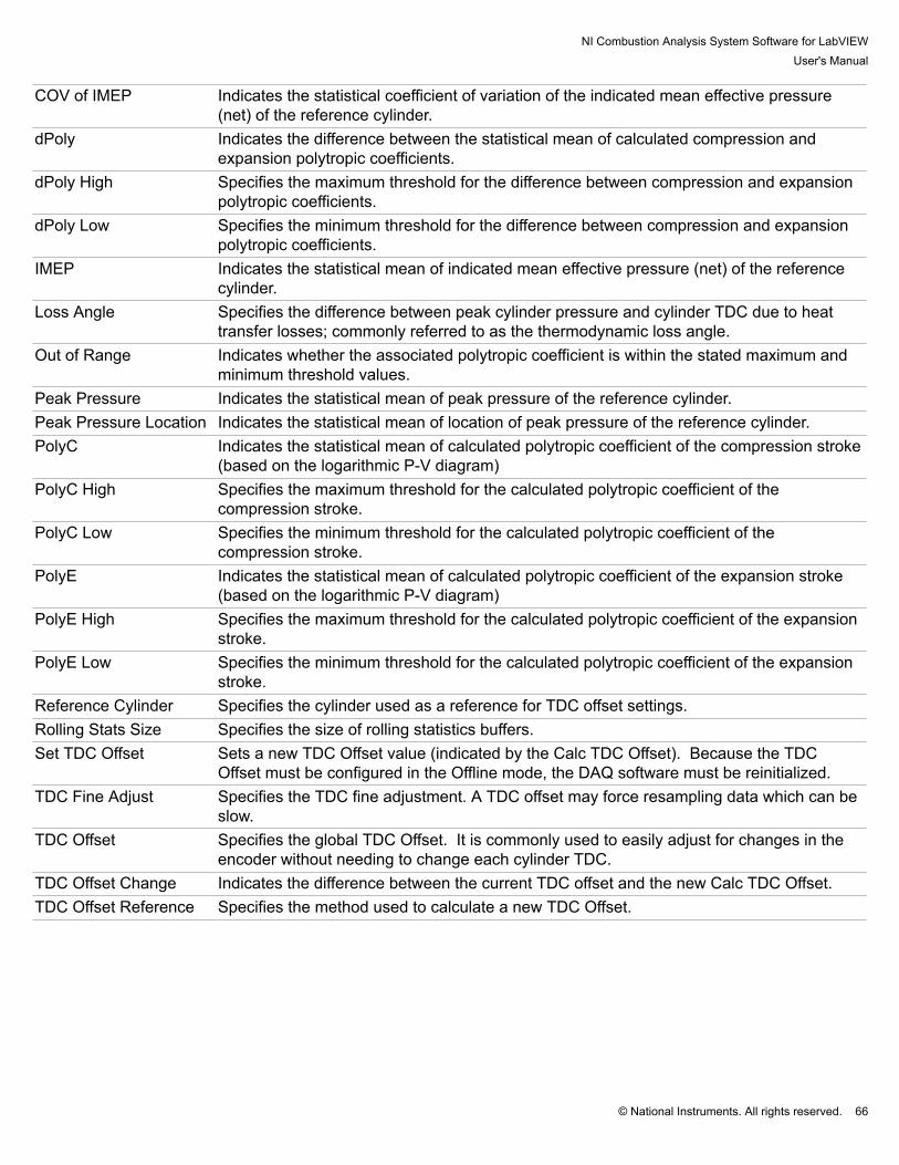
NI Combustion Analysis System Software for LabVIEWUser's Manual
© National Instruments. All rights reserved. 66
COV of IMEP Indicates the statistical coefficient of variation of the indicated mean effective pressure(net) of the reference cylinder.
dPoly Indicates the difference between the statistical mean of calculated compression andexpansion polytropic coefficients.
dPoly High Specifies the maximum threshold for the difference between compression and expansionpolytropic coefficients.
dPoly Low Specifies the minimum threshold for the difference between compression and expansionpolytropic coefficients.
IMEP Indicates the statistical mean of indicated mean effective pressure (net) of the referencecylinder.
Loss Angle Specifies the difference between peak cylinder pressure and cylinder TDC due to heattransfer losses; commonly referred to as the thermodynamic loss angle.
Out of Range Indicates whether the associated polytropic coefficient is within the stated maximum andminimum threshold values.
Peak Pressure Indicates the statistical mean of peak pressure of the reference cylinder.Peak Pressure Location Indicates the statistical mean of location of peak pressure of the reference cylinder.PolyC Indicates the statistical mean of calculated polytropic coefficient of the compression stroke
(based on the logarithmic P-V diagram)PolyC High Specifies the maximum threshold for the calculated polytropic coefficient of the
compression stroke.PolyC Low Specifies the minimum threshold for the calculated polytropic coefficient of the
compression stroke.PolyE Indicates the statistical mean of calculated polytropic coefficient of the expansion stroke
(based on the logarithmic P-V diagram)PolyE High Specifies the maximum threshold for the calculated polytropic coefficient of the expansion
stroke.PolyE Low Specifies the minimum threshold for the calculated polytropic coefficient of the expansion
stroke.Reference Cylinder Specifies the cylinder used as a reference for TDC offset settings.Rolling Stats Size Specifies the size of rolling statistics buffers.Set TDC Offset Sets a new TDC Offset value (indicated by the Calc TDC Offset). Because the TDC
Offset must be configured in the Offline mode, the DAQ software must be reinitialized.TDC Fine Adjust Specifies the TDC fine adjustment. A TDC offset may force resampling data which can be
slow.TDC Offset Specifies the global TDC Offset. It is commonly used to easily adjust for changes in the
encoder without needing to change each cylinder TDC.TDC Offset Change Indicates the difference between the current TDC offset and the new Calc TDC Offset.TDC Offset Reference Specifies the method used to calculate a new TDC Offset.
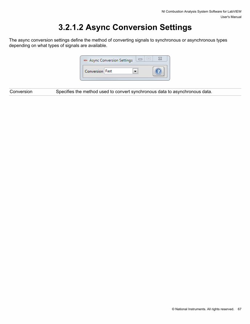
NI Combustion Analysis System Software for LabVIEWUser's Manual
© National Instruments. All rights reserved. 67
3.2.1.2 Async Conversion Settings The async conversion settings define the method of converting signals to synchronous or asynchronous typesdepending on what types of signals are available.
Conversion Specifies the method used to convert synchronous data to asynchronous data.

NI Combustion Analysis System Software for LabVIEWUser's Manual
© National Instruments. All rights reserved. 68
3.2.1.3 Pegging Settings Many of the sensors used for in-cylinder applications are relative or dynamic measurements. They are accuratein representing the change in pressure over a short period but do not represent an absolute vale. To compensate,pegging (calculating a dynamic offset) is used.
1. Detailed setup of the selected measurement.2. Plot of current signals and windows.3. Selection of cylinder to display.
Location Specifies the location used to peg cylinder pressure when using constant and synchronous
MAP pegging.Pegging Specifies the method used to peg cylinder pressure.Pegging Pressure Specifies the pressure used to peg cylinder pressure when using constant pegging.Polytropic Exponent Specifies the polytropic exponent used for polytropic pegging.Window The crank angle window size used to average noise in synchronous waveform
measurements.

NI Combustion Analysis System Software for LabVIEWUser's Manual
© National Instruments. All rights reserved. 69
3.2.1.4 Filter Settings The filter settings define all the filters for engine synchronous and time-based asynchronous measurements.Each measurement can be configured to a filter resource. The filter resources can be attached to a one or moremeasurements.
1. Detailed settings for each filter resource.2. Plot of current signals and windows.3. Selection of filter resource and signal to plot.
Filter Defines the type of filter used.Frequency Defines the filter frequency as a percent of the nyquist frequency. This value is only valid
when using FIR and IIR filters.N Defines the number of cycles to include in the rolling average or the number of samples to
include in the boxcar average.Order Defines the order of the filter when using the FIR and IIR filters.

NI Combustion Analysis System Software for LabVIEWUser's Manual
© National Instruments. All rights reserved. 70
3.2.1.5 Pressure Metrics Settings The pressure metrics settings define parameters for the pressure metrics calculation group.
1. Detailed settings for the basic calculation group.2. Plot of current signals and windows.
Endpoint Window Specifies the size of the window used to average the endpoints when calculating
the polytropic exponents.Exhaust Pressure End Specifies the end of the exhaust pressure calculation.Exhaust Pressure Start Specifies the start of the exhaust pressure calculation.Intake Pressure End Specifies the end of the intake pressure calculation.Intake Pressure Start Specifies the start of the intake pressure calculation.Peak Pressure Specifies the method used to calculate the peak pressure.Peak Pressure End Specifies the end of the peak pressure window.Peak Pressure Start Specifies the start of the peak pressure window.Polytropic Specifies the method used to calculate the polytropic exponents.Polytropic Compression End Specifies the end of the polytropic compression calculation.Polytropic Compression Start Specifies the start of the polytropic compression calculation.Polytropic Expansion End Specifies the end of the polytropic expansion calculation.

NI Combustion Analysis System Software for LabVIEWUser's Manual
© National Instruments. All rights reserved. 71
Polytropic Expansion Start Specifies the start of the polytropic expansion calculation.

NI Combustion Analysis System Software for LabVIEWUser's Manual
© National Instruments. All rights reserved. 72
3.2.1.6 Unit Conversions Settings The unit conversion dialog allows the user to define a set of unit conversion rules. The rules affect the tables, trends,and plots. They do not change the units of settings or results in a file.

NI Combustion Analysis System Software for LabVIEWUser's Manual
© National Instruments. All rights reserved. 73
3.2.1.7 Temperature Settings The temperature settings define how the in-cylinder temperature estimation is calculated.
Exhaust Pressure Pressure of the intake gas at the intake valve.Exhaust Temperature Temperature of the exhaust gas at the exhaust valve.Intake Pressure Pressure of the exhaust gas at the exhaust valve.Intake Temperature Temperature of the intake gas at the intake valve.Residual Fraction Fraction of exhaust gas remaining in the combustion chamber after the exhaust event.Window The crank angle window size used to average noise in synchronous waveform
measurements.

NI Combustion Analysis System Software for LabVIEWUser's Manual
© National Instruments. All rights reserved. 74
3.2.1.8 Heat Release Settings The heat release settings define what settings are used for the various methods of calculating heat release.
C1c Woschni Coefficient 1 for Compression (Default = 2.28).C1e Woschni Coefficient 1 for Combustion and Expansion (Default = 2.28).C1ge Woschni Coefficient 1 for Gas Exchange (Default = 6.18).C2c Woschni Coefficient 2 for Compression (Default = 0.0).C2e Woschni Coefficient 2 for Combustion and Expansion (Default = 0.00324).C2ge Woschni Coefficient 2 for Gas Exchange (Default = 0.0).End Angle Specifies the angle to end looking for the end of combustion.End of Combustion Specifies the method used to determine the end of combustion.Heat Release Specifies the method used to calculate heat release.Heat Transfer Defines the heat transfer when using the constant Heat Transfer Correlation method.Heat Transfer Correlation Specifies the method used to calculate the Heat Transfer Correlation.N End Specifies the number of samples to use when determining the end of combustion.N Start Specifies the number of samples to use when determining the start of combustion.Polytropic Correlation Specifies the method use to calculate the polytropic exponent.PreChamber Volume Specifies the volume of the prechamber used in dual transducer calculations.Smoothing Pressure waveform smoothing factor as a percent of one engine cycle.

NI Combustion Analysis System Software for LabVIEWUser's Manual
© National Instruments. All rights reserved. 75
Start Angle Specifies the angle to start looking for the start of combustion.Start of Combustion Specifies the method used to determine the start of combustion.User Heat Release VI Specifies the file location of the user heat release VI, if used.
Wall Temperature Specifies the Wall Temperature when using the constant Wall Temperature Profile.Wall Temperature BDC Specifies the Bottom Dead Center Wall Temperature when using the linear Wall
Temperature ProfileWall Temperature Profile Specifies the method used to calculate the cylinder Wall Temperature Profile.Wall Temperature TDC Specifies the Top Dead Center Wall Temperature when using the linear Wall
Temperature Profilea Defines the Polytropic Exponent Correlation "a" Value when using custom Polytropic
Correlation.b Defines the Polytropic Exponent Correlation "b" Value when using custom Polytropic
Correlation.

NI Combustion Analysis System Software for LabVIEWUser's Manual
© National Instruments. All rights reserved. 76
3.2.1.9 Knock Settings The knock settings determine how knock is detected. The knock settings dialog provides information and displaysthat are helpful for calibrating the knock settings.
1. Summary of settings for each cylinder.2. Detailed setup of the selected measurement.3. Calibration setup displays.4. Hold and clear for up to 7 cycles. Pressing the buttons captures the current waveforms for comparison.
High Cutoff Frequency Specifies the High Cutoff Frequency of the knock filter for each cylinder.Knock End Specifies the crank angle to end the knock window for each cylinder.Knock Start Specifies the crank angle to start the knock window for each cylinder.Low Cutoff Frequency Specifies the Low Cutoff Frequency of the knock filter for each cylinder.Minimum Reference Specifies the Minimum Reference Value used to remove noise for each cylinder.Reference End Specifies the crank angle to end the reference window for each cylinder.Reference Start Specifies the crank angle to start the reference window for each cylinder.Threshold Specifies the knock threshold for each cylinder.

NI Combustion Analysis System Software for LabVIEWUser's Manual
© National Instruments. All rights reserved. 77
Calibrating knock is a delicate process of capturing various degrees of knock and comparing them to determinewhere the unacceptable level of knock occurs. Changing settings will reprocess all the held data so the new settingscan be evaluated over the range of operating conditions. The process of calibrating knock starts with setting upwindows for checking for knock and reference noise. The Signal page shows the current cycle of pressure data andthe acoustic waveform. The knock window should be located around TDC. The reference window should be locatedaway from noise caused by valve closings and other noisy events.
The next step in calibrating knock is to determine the knocking frequency. The frequency magnitude should be realitystable unless knocking. Therefore, the filter frequencies should include the knocking event but not other events.The filter cutoffs page displays the FFT of the for the knock and reference windows. The first three theoreticalfundamental frequencies (based on cylinder bore) are calculated and displayed for reference.

NI Combustion Analysis System Software for LabVIEWUser's Manual
© National Instruments. All rights reserved. 78
Next, the filter results for the knock and reference window are displayed on the filter results page.

NI Combustion Analysis System Software for LabVIEWUser's Manual
© National Instruments. All rights reserved. 79
Last, the filtered window results are integrated and compared. The threshold should be set to determine whereknock starts. The threshold is removed to get the final knock value. Any value above zero is considered knock.Greater knock values indicate greater levels of knock. The threshold page shows the results of the integration andthe raw and final results of the comparison.
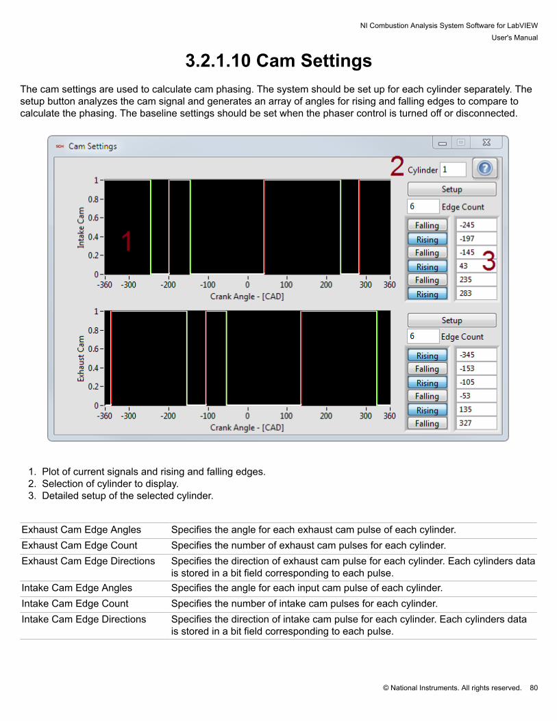
NI Combustion Analysis System Software for LabVIEWUser's Manual
© National Instruments. All rights reserved. 80
3.2.1.10 Cam Settings The cam settings are used to calculate cam phasing. The system should be set up for each cylinder separately. Thesetup button analyzes the cam signal and generates an array of angles for rising and falling edges to compare tocalculate the phasing. The baseline settings should be set when the phaser control is turned off or disconnected.
1. Plot of current signals and rising and falling edges.2. Selection of cylinder to display.3. Detailed setup of the selected cylinder.
Exhaust Cam Edge Angles Specifies the angle for each exhaust cam pulse of each cylinder.Exhaust Cam Edge Count Specifies the number of exhaust cam pulses for each cylinder.Exhaust Cam Edge Directions Specifies the direction of exhaust cam pulse for each cylinder. Each cylinders data
is stored in a bit field corresponding to each pulse.Intake Cam Edge Angles Specifies the angle for each input cam pulse of each cylinder.Intake Cam Edge Count Specifies the number of intake cam pulses for each cylinder.Intake Cam Edge Directions Specifies the direction of intake cam pulse for each cylinder. Each cylinders data
is stored in a bit field corresponding to each pulse.

NI Combustion Analysis System Software for LabVIEWUser's Manual
© National Instruments. All rights reserved. 81
3.2.1.11 Injection Settings The injection settings define how injection waveforms are processed. The injection calculations measure startingangle, duration, and fuel flow for each injection.
Fuel Rail Pressure Defines the fuel rail pressure of the injectors.Fuel Rail PressureSource
Determines the source of the fuel rail pressure used in determining fuel flow.
Min Injection Defines the minimum injection width.Signal Defines the injector signal type.Type Defines the injector type.X-Fuel Pressure Defines the X-Axis (Fuel Pressure) of the 2d injector calibration table.Y-Duration Defines the Y-Axis (Duration) of the 2d injector calibration table.Z-Fuel Flow Defines the Z-Axis (Fuel Flow) of the 2d injector calibration table.

NI Combustion Analysis System Software for LabVIEWUser's Manual
© National Instruments. All rights reserved. 82
3.2.1.12 Spark Settings The spark setting determine how spark signals are processed. The spark calculations determine the spark angel anddwell for each spark.
Min Dwell Defines the minimum dwell width.Restrike Delay Defines the maximum restrike delay.Signal Defines the spark signal type.

NI Combustion Analysis System Software for LabVIEWUser's Manual
© National Instruments. All rights reserved. 83
3.2.1.13 Misfire Settings The misfire settings determine how a misfire event is determined.
Misfire Specifies the method to use for Misfire detection.Threshold Specifies the threshold used to detect a misfire. The use of the value depends on the misfire
method used.

NI Combustion Analysis System Software for LabVIEWUser's Manual
© National Instruments. All rights reserved. 84
3.2.1.14 Simulation Settings The simulation settings allow the user to control how simulated waveforms are generated. The simulation is enabledon the engine setup page.
1. Speed and load settings.2. Simulated settings mode. Lookup tables adjust detailed settings based on speed and load. Run profile runs the
pre-defined profile.3. Detailed simulation settings.4. Pre-defined profile.
Cam Start Specifies the simulated cam start.Exhaust Cam Specifies the simulated exhaust cam offset.Fuel Rail Pressure Specifies the simulated fuel rail pressure.Injection Duration Specifies the simulated injection duration.Injection Location Specifies the simulated injection locationsIntake Cam Specifies the simulated intake cam offset.Manifold Absolute Pressure Specifies the simulated manifold absolute pressure.PWM Duty Cycle Specifies the simulated pulse width width measurement duty cycle.
NI Combustion Analysis System Software for LabVIEWUser's Manual
© National Instruments. All rights reserved. 85
PWM Frequency Specifies the simulated pulse width width measurement frequency.Spark Dwell Specifies the simulated spark dwell.Spark Location Specifies the simulated spark location.Speed Specifies the simulated engine speed.Synchronous Pump Duration Specifies the simulated synchronous pump duration.Synchronous Pump Start Specifies the simulated synchronous pump start.

NI Combustion Analysis System Software for LabVIEWUser's Manual
© National Instruments. All rights reserved. 86
3.2.2 File Save

NI Combustion Analysis System Software for LabVIEWUser's Manual
© National Instruments. All rights reserved. 87
3.2.2.1 Raw File Save NI CAS Software raw files contain all of the data as it comes from the DAQ system and all of the settings enteredby the user. This data can be used to generate summary data. Because all of the data is saved in a raw format,calibrations and other settings can be modified and applied the calculations when reprocessing. However, the datain the file need some processing before it is useful in most user applications. NI CAS Software contains severalapplications, examples, and an API for using raw data files.
Start-Stop File Starts saving a file if currently stopped or stops saving a file if currently stopped.Standby / Writing Displays the state of the file writing process.New File / Overwrite Indicates if a new file will be written or an old file will be overwritten.Sum + Raw Presses the "Start-Stop File" buttons on "Raw File" and "Sum File" dialogs at the same
time.File Path Current files path and name when saving.Path Location on the target system where data will be saved.File Name Name of saved files. "XXX" is replaced by the "File Counter" and standard data/time
formats (%c) are applied to the name.Comments User comments added to the file.Single / Continuous Single - One file is written and saving stops. / Continuous - A new file is started when the
previous one finishes. File Part increments by on for each file. The saving process must bestopped manually.

NI Combustion Analysis System Software for LabVIEWUser's Manual
© National Instruments. All rights reserved. 88
File Part Indicates the current part of a continuous multi-part save.Size Limit Enables a size limit on file saving and defines the maximum file size.Time Limit Enables a time limit on file saving and defines the maximum time.Cycle Limit Enables a cycle limit on file saving and defines the maximum number of cycle.File Counter Indicates the current file count.Reset Counter Value Desired value to set "File Counter" to when "Reset Counter" button is pressed.Reset Counter Resets the file counter to the "Reset Counter Value".File Progress Indicates the approximate status of the file save compared with the file limit conditions.Process File Contains a path to a VI on the target system that will be used to process the files after a
save operation. Leave it blank to disable file processing.File Indicates the current file that is processing and any files waiting to be processed.Error Indicates any error associated with file processing.
Data/Time Format:%X (locale-specific time)%H (hour, 24-hour clock)%I (hour, 12-hour clock)%M (minute)%S (second)%<digit>u (fractional seconds with <digit> precision)%p (a.m./p.m. flag)%x (locale-specific date)%y (year within century)%Y (year including century)%m (month number)%b (abbreviated month name)%d (day of month)%a (abbreviated weekday name)

NI Combustion Analysis System Software for LabVIEWUser's Manual
© National Instruments. All rights reserved. 89
3.2.2.2 Summary File Save NI CAS Software summary files contain all of the calculated results all of the settings entered by the user. The filealso contains statistics on all the results. Ensemble averages are included for user reference.
Start-Stop File Starts saving a file if currently stopped or stops saving a file if currently stopped.Standby / Writing Displays the state of the file writing process.New File / Overwrite Indicates if a new file will be written or an old file will be overwritten.Sum + Raw Presses the "Start-Stop File" buttons on "Raw File" and "Sum File" dialogs at the same
time.File Path Current files path and name when saving.Path Location on the target system where data will be saved.File Name Name of saved files. "XXX" is replaced by the "File Counter" and standard data/time
formats (%c) are applied to the name.Comments User comments added to the file.Single / Continuous Single - One file is written and saving stops. / Continuous - A new file is started when the
previous one finishes. File Part increments by on for each file. The saving process must bestopped manually.
File Part Indicates the current part of a continuous multi-part save.Size Limit Enables a size limit on file saving and defines the maximum file size.

NI Combustion Analysis System Software for LabVIEWUser's Manual
© National Instruments. All rights reserved. 90
Time Limit Enables a time limit on file saving and defines the maximum time.Cycle Limit Enables a cycle limit on file saving and defines the maximum number of cycle.File Counter Indicates the current file count.Reset Counter Value Desired value to set "File Counter" to when "Reset Counter" button is pressed.Reset Counter Resets the file counter to the "Reset Counter Value".File Progress Indicates the approximate status of the file save compared with the file limit conditions.Process File Contains a path to a VI on the target system that will be used to process the files after a
save operation. Leave it blank to disable file processing.File Indicates the current file that is processing and any files waiting to be processed.Error Indicates any error associated with file processing.
Data/Time Format:%X (locale-specific time)%H (hour, 24-hour clock)%I (hour, 12-hour clock)%M (minute)%S (second)%<digit>u (fractional seconds with <digit> precision)%p (a.m./p.m. flag)%x (locale-specific date)%y (year within century)%Y (year including century)%m (month number)%b (abbreviated month name)%d (day of month)%a (abbreviated weekday name)

NI Combustion Analysis System Software for LabVIEWUser's Manual
© National Instruments. All rights reserved. 91
3.2.3 Status

NI Combustion Analysis System Software for LabVIEWUser's Manual
© National Instruments. All rights reserved. 92
3.2.3.1 Engine The engine status display shows the current speed of the engine. It also shows the running time and engine cycle.
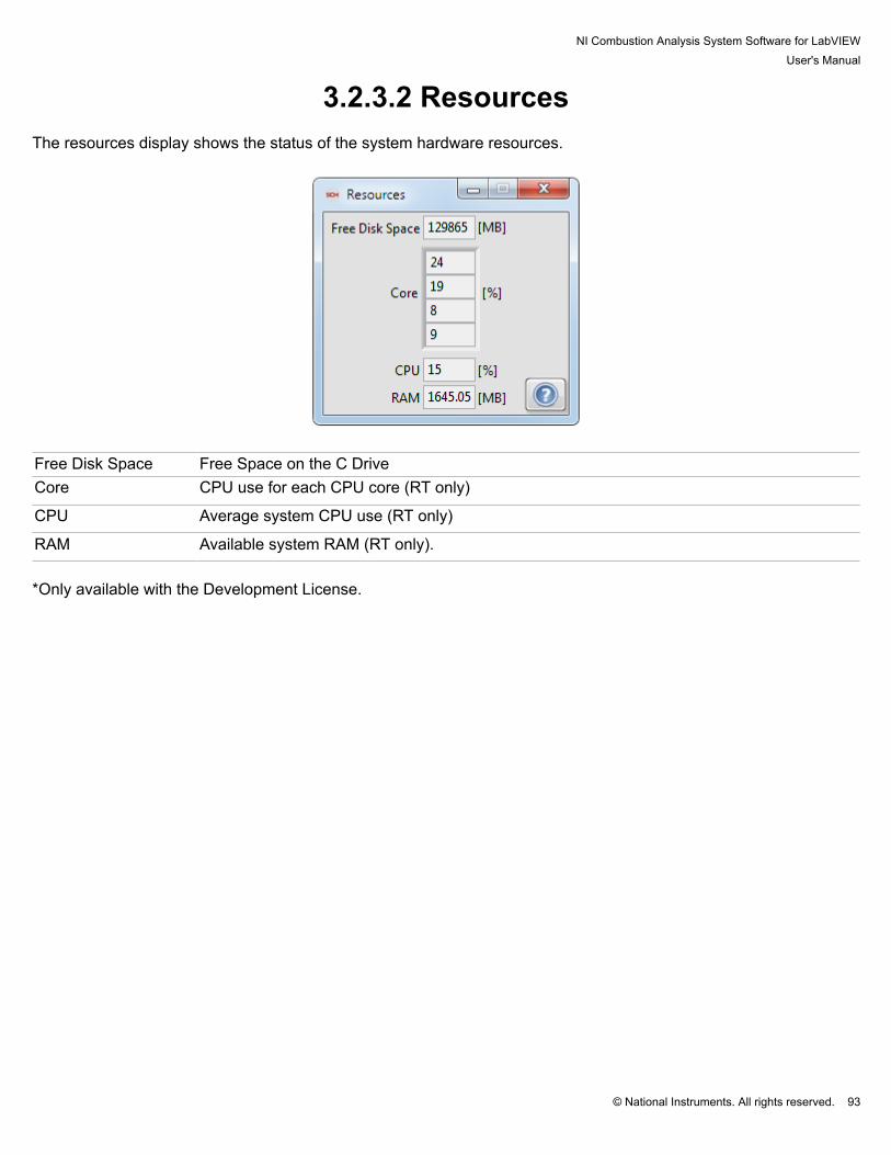
NI Combustion Analysis System Software for LabVIEWUser's Manual
© National Instruments. All rights reserved. 93
3.2.3.2 Resources The resources display shows the status of the system hardware resources.
Free Disk Space Free Space on the C DriveCore CPU use for each CPU core (RT only)
CPU Average system CPU use (RT only)
RAM Available system RAM (RT only). *Only available with the Development License.
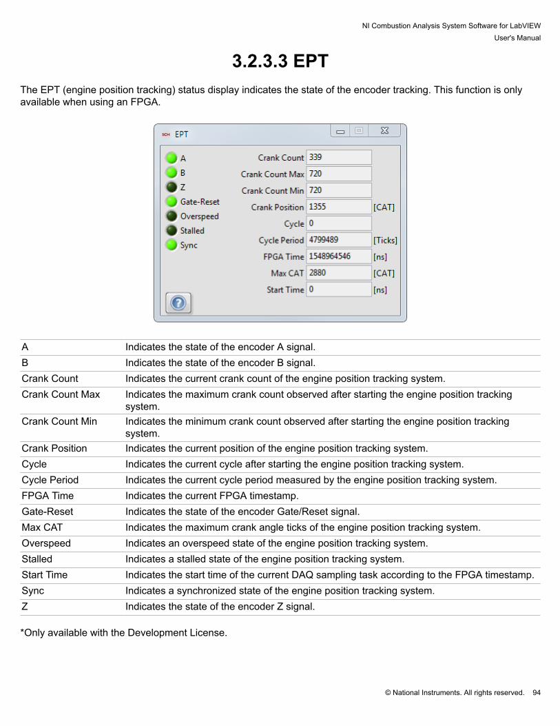
NI Combustion Analysis System Software for LabVIEWUser's Manual
© National Instruments. All rights reserved. 94
3.2.3.3 EPT The EPT (engine position tracking) status display indicates the state of the encoder tracking. This function is onlyavailable when using an FPGA.
A Indicates the state of the encoder A signal.B Indicates the state of the encoder B signal.Crank Count Indicates the current crank count of the engine position tracking system.Crank Count Max Indicates the maximum crank count observed after starting the engine position tracking
system.Crank Count Min Indicates the minimum crank count observed after starting the engine position tracking
system.Crank Position Indicates the current position of the engine position tracking system.Cycle Indicates the current cycle after starting the engine position tracking system.Cycle Period Indicates the current cycle period measured by the engine position tracking system.FPGA Time Indicates the current FPGA timestamp.Gate-Reset Indicates the state of the encoder Gate/Reset signal.Max CAT Indicates the maximum crank angle ticks of the engine position tracking system.Overspeed Indicates an overspeed state of the engine position tracking system.Stalled Indicates a stalled state of the engine position tracking system.Start Time Indicates the start time of the current DAQ sampling task according to the FPGA timestamp.Sync Indicates a synchronized state of the engine position tracking system.Z Indicates the state of the encoder Z signal. *Only available with the Development License.

NI Combustion Analysis System Software for LabVIEWUser's Manual
© National Instruments. All rights reserved. 95
3.2.3.4 Execution The execution status display indicates execution time of each processing and calculation step. The calculations canbe enabled or disabled using Calculations.vi.
1. Calculation Time - Calculation time for each processing or calculation step.2. Name and Color - Name and color of the processing or calculation step.3. Calculation Time - Graphical representation of calculation time. The plot maximum is the maximum allotted time
available to finish the calculations.
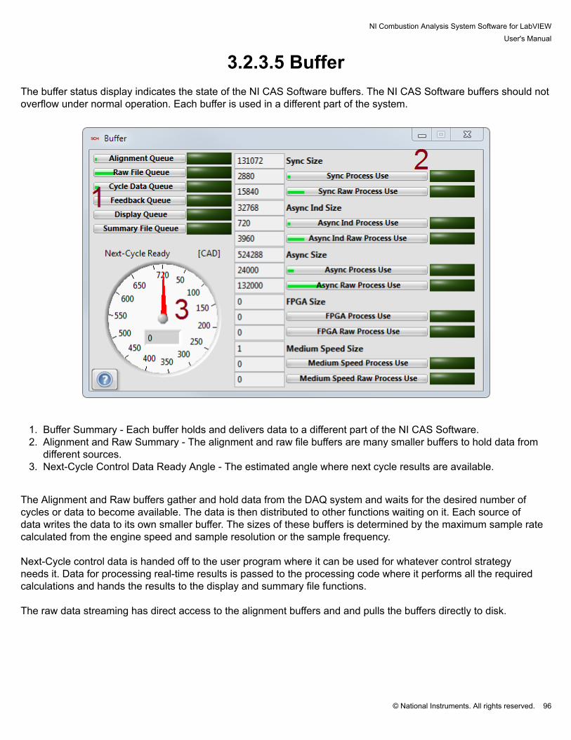
NI Combustion Analysis System Software for LabVIEWUser's Manual
© National Instruments. All rights reserved. 96
3.2.3.5 Buffer The buffer status display indicates the state of the NI CAS Software buffers. The NI CAS Software buffers should notoverflow under normal operation. Each buffer is used in a different part of the system.
1. Buffer Summary - Each buffer holds and delivers data to a different part of the NI CAS Software.2. Alignment and Raw Summary - The alignment and raw file buffers are many smaller buffers to hold data from
different sources.3. Next-Cycle Control Data Ready Angle - The estimated angle where next cycle results are available.
The Alignment and Raw buffers gather and hold data from the DAQ system and waits for the desired number ofcycles or data to become available. The data is then distributed to other functions waiting on it. Each source ofdata writes the data to its own smaller buffer. The sizes of these buffers is determined by the maximum sample ratecalculated from the engine speed and sample resolution or the sample frequency. Next-Cycle control data is handed off to the user program where it can be used for whatever control strategyneeds it. Data for processing real-time results is passed to the processing code where it performs all the requiredcalculations and hands the results to the display and summary file functions. The raw data streaming has direct access to the alignment buffers and and pulls the buffers directly to disk.
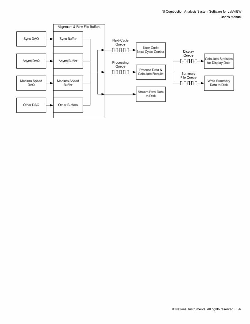
NI Combustion Analysis System Software for LabVIEWUser's Manual
© National Instruments. All rights reserved. 97

NI Combustion Analysis System Software for LabVIEWUser's Manual
© National Instruments. All rights reserved. 98
3.2.3.6 Loop The loop status display indicates execution status of each NI CAS Software loop.
1. Loop Count - Shows the current iteration of the specified loop.2. Loop Period - Shows the current period of the specified loop.3. Loop Time - Shows the current execution time of the specified loop.

NI Combustion Analysis System Software for LabVIEWUser's Manual
© National Instruments. All rights reserved. 99
3.2.3.7 Error The error status display shows an error and warning message for each loop in the NI CAS Software. The errors areaccompanied with an error number and an error message. An new error state will cause the window to open.

NI Combustion Analysis System Software for LabVIEWUser's Manual
© National Instruments. All rights reserved. 100
3.3 Results

NI Combustion Analysis System Software for LabVIEWUser's Manual
© National Instruments. All rights reserved. 101
3.3.1 X-AxisAll plots using "Crank Angle" as the X-axis can be modified collectively by using the plot scaling tool at the top of the"Plots" tab. The plot scaling tool contains several preset values that are commonly used to look at data, as well as acustom setting which can be used to enter values not included in the presets.

NI Combustion Analysis System Software for LabVIEWUser's Manual
© National Instruments. All rights reserved. 102
3.3.2 Plots Plots display data in array form. The NI CAS Software contains several different typed of plots that are used fordifferent kinds of data. Plots using "Crank Angle" as the x-axis have global settings using the X-Axis controls. Mostplots are resizable by dragging the corner or side of the window.
This type of plot displays analog results for a single cylinder and a single cycle of data at a time.
1. Plot Legend - Displays plot names and units with the ability to turn off a plot.2. Plot Data - Data display area.3. Plot Controls - Controls for controlling zoom and cursors.4. Cylinder Selection - Select the cylinder to display.5. Y-Axis mode - Select between using absolute units or % of range for the Y-axis.

NI Combustion Analysis System Software for LabVIEWUser's Manual
© National Instruments. All rights reserved. 103
This type of plot displays digital results for a single cylinder of data at a time.
1. Plot Legend - Displays plot names with the ability to turn off a plot.2. Plot Data - Data display area.3. Plot Controls - Controls for controlling zoom and cursors.4. Cylinder Selection - Select the cylinder to display.5. Y-Axis mode - Select between using a separate or combined Y-axis.
*Only available with the Development License.

NI Combustion Analysis System Software for LabVIEWUser's Manual
© National Instruments. All rights reserved. 104
This plot displays the results of the volume calculations or loading a volume file.
1. Volume - Cylinder volume as a function of crank angle.2. dVolume - Differential cylinder volume as a function of crank angle.3. Cylinder Area - Cylinder, head, and piston area as a function of crank angle.

NI Combustion Analysis System Software for LabVIEWUser's Manual
© National Instruments. All rights reserved. 105
This type of plot displays the results of a specific type of signal for all the cylinders and engine average for a singlecycle.
1. Plot Legend - Displays plot names and units with the ability to turn off a plot.2. Plot Data - Data display area.3. Plot Controls - Controls for controlling zoom and cursors.
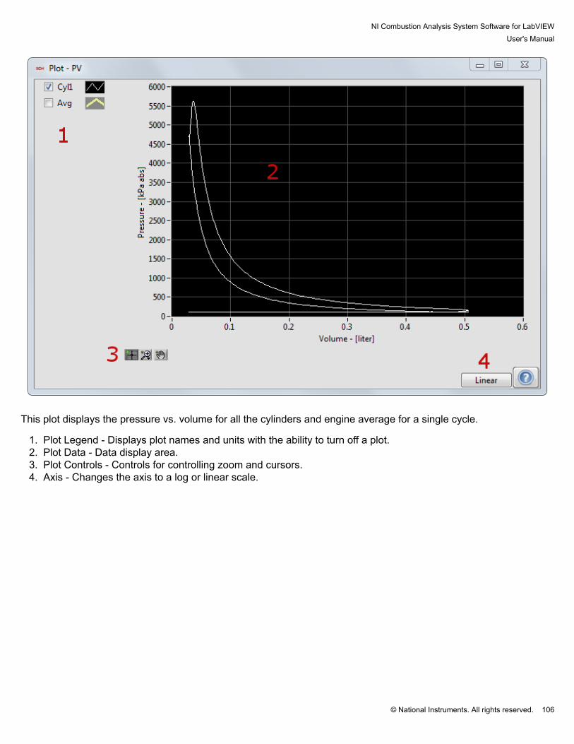
NI Combustion Analysis System Software for LabVIEWUser's Manual
© National Instruments. All rights reserved. 106
This plot displays the pressure vs. volume for all the cylinders and engine average for a single cycle.
1. Plot Legend - Displays plot names and units with the ability to turn off a plot.2. Plot Data - Data display area.3. Plot Controls - Controls for controlling zoom and cursors.4. Axis - Changes the axis to a log or linear scale.

NI Combustion Analysis System Software for LabVIEWUser's Manual
© National Instruments. All rights reserved. 107
This plot displays the pressure vs. volume for a single cylinder and a single cycle.
1. Plot Legend - Displays the name and color for each stroke.2. Plot Data - Data display area.3. Plot Controls - Controls for controlling zoom and cursors.4. Cylinder Selection - Select the cylinder to display.5. Axis - Changes the axis to a log or linear scale.

NI Combustion Analysis System Software for LabVIEWUser's Manual
© National Instruments. All rights reserved. 108
3.3.3 Tables Tables contain all of the calculated values and rolling statistics for each result. The results are grouped by calculationgroup that can be turned on or off. See Calculations.vi to turn or off the calculation groups.
1. Show Statistics - Turns on or off rows of statistics.2. Parameter - A list of parameters calculated by the specific calculation group.3. Values - Calculation results for each cylinder and the engine average for multi-cylinder engines.

NI Combustion Analysis System Software for LabVIEWUser's Manual
© National Instruments. All rights reserved. 109
3.3.4 Trend ChartsTrend charts contain a history of all the calculated values and rolling statistics. The trend chart captures the currentvalues at a fixed rate. Therefore, they are good for looking at global trends and not for individual cycle events. Theresults are grouped by calculation group that can be turned on or off. See Calculations.vi to turn or off the calculationgroups.
1. Parameter - A list of parameters calculated by the specific calculation group.2. Show Statistics - Turns on or off rows of statistics.3. Values - History of calculated results.4. Plot Controls - Controls for controlling zoom and cursors.

NI Combustion Analysis System Software for LabVIEWUser's Manual
© National Instruments. All rights reserved. 110
4. Processing and Calculations

NI Combustion Analysis System Software for LabVIEWUser's Manual
© National Instruments. All rights reserved. 111
4.1 Cylinder Volume Cylinder volume is calculated using the following equation for the typical crank-slider mechanism (no wrist-pinoffset)1,2 :
For engines requiring a wrist-pin offset, the following geometry calculations are used:
where:
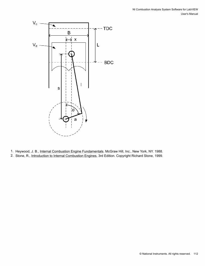
NI Combustion Analysis System Software for LabVIEWUser's Manual
© National Instruments. All rights reserved. 112
1. Heywood, J. B., Internal Combustion Engine Fundamentals. McGraw Hill, Inc., New York, NY. 1988.2. Stone, R., Introduction to Internal Combustion Engines, 3rd Edition. Copyright Richard Stone, 1999.
NI Combustion Analysis System Software for LabVIEWUser's Manual
© National Instruments. All rights reserved. 113
4.2 Waveform Filters Four different filter types with customizable parameters can be used to remove unwanted noise from thesynchronous and asynchronous signals: Boxcar, Rolling N Cycles, Forward and Reverse IIR, and FIR Filter withRollback.
NI Combustion Analysis System Software for LabVIEWUser's Manual
© National Instruments. All rights reserved. 114
4.2.1 Boxcar The 'Boxcar' filter requires 'N' points for input. This filter, also known as a 'moving average,' is a very simple FIR filterwhich smoothes a signal by 'marching' through the waveform and averaging 'N' points before and after each givenpoint (including the point itself).
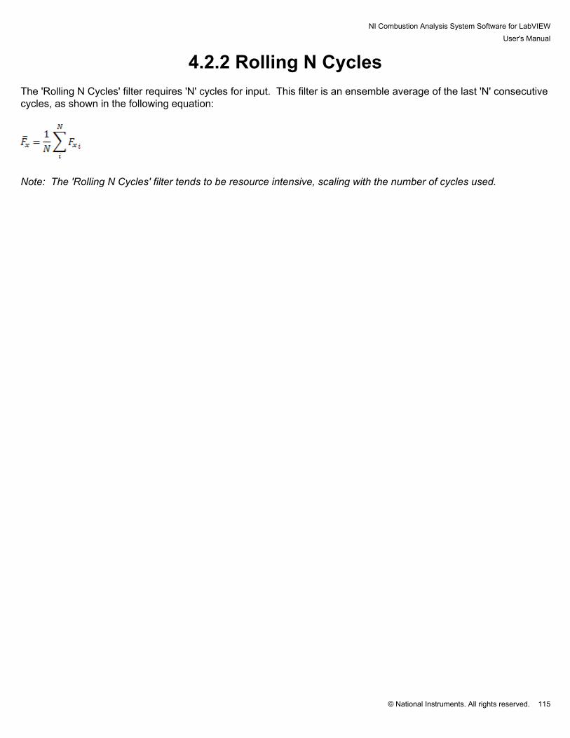
NI Combustion Analysis System Software for LabVIEWUser's Manual
© National Instruments. All rights reserved. 115
4.2.2 Rolling N Cycles The 'Rolling N Cycles' filter requires 'N' cycles for input. This filter is an ensemble average of the last 'N' consecutivecycles, as shown in the following equation:
Note: The 'Rolling N Cycles' filter tends to be resource intensive, scaling with the number of cycles used.
NI Combustion Analysis System Software for LabVIEWUser's Manual
© National Instruments. All rights reserved. 116
4.2.3 Forward and Reverse IIR The 'Forward and Reverse Infinite Impulse Response (IIR)' filter requires filtering frequency (lowpass) and filter orderinputs. The Butterworth filtering method is used, with a sampling frequency of 200 Hz. The filter order dictates theresponse of the signal roll-off, where a higher order has a steeper roll-off. This filter is passed in both forward and reverse directions to avoid shifting the phase of the waveform.

NI Combustion Analysis System Software for LabVIEWUser's Manual
© National Instruments. All rights reserved. 117
4.2.4 FIR Filter with Rollback The 'FIR Filter with Rollback' requires filtering frequency (lowpass) and filter order inputs. This filter is a backward-looking 'moving average' which smoothes a signal by 'marching' through the waveform and averaging 'N - 1' pointsbefore each given point (including the point itself). In this case, 'N' is also the filter order. This filter method shifts the phase of the waveform N/2 points to the right, therefore rollback is necessary to correctthe phase of the signal.

NI Combustion Analysis System Software for LabVIEWUser's Manual
© National Instruments. All rights reserved. 118
4.3 Cylinder Pressure Pegging In the case that in-cylinder pressure is measured using a dynamic pressure transducer (e.g., piezoelectric), thecaptured waveform must be 'pegged' to an absolute value in order to obtain accurate results. Using this software,cylinder pressure can be pegged using a constant value, synchronous manifold absolute pressure (MAP) signal, or apolytropic coefficient. Note: If a pre-chamber pressure is used, it will be pegged in the same manner as the primarycylinder pressure.

NI Combustion Analysis System Software for LabVIEWUser's Manual
© National Instruments. All rights reserved. 119
4.3.1 Constant The 'Constant' pegging setting requires a constant, scalar value as the pegging reference, a pegging location, and apegging window. The pegging location (typically near a relatively quiescent period within the cycle and while the intake valve(s)are open) specifies the crank angle at which the pegging reference will exactly equal the average of the cylinderpressure waveform over a given pegging window. The pegging window is centered about the pegging location.

NI Combustion Analysis System Software for LabVIEWUser's Manual
© National Instruments. All rights reserved. 120
4.3.2 Synchronous MAP The 'Synchronous MAP' pegging setting requires a configured sync analog channel (Manifold Absolute Pressure -kPa) as the pegging reference, a pegging location, and a pegging window. The pegging location (typically near a relatively quiescent period within the cycle and while the intake valve(s)are open) specifies the crank angle at which the pegging reference will exactly equal the average of the cylinderpressure waveform over a given pegging window. The pegging window is centered about the pegging location.

NI Combustion Analysis System Software for LabVIEWUser's Manual
© National Instruments. All rights reserved. 121
4.3.3 Polytropic The 'Polytropic' pegging setting requires a pegging location, a pegging window, and a constant polytropic coefficientto define the pegging reference. The pegging location / window should be positioned during the compression stroke after the intake valve is closed,e.g., from -90 to -60 DATDC. The following calculations are used to define the pegging reference:
Where location 1 and 2 are the average values at the respective endpoints of the pegging window specified, 'P' ispressure, 'V' is volume, and 'n' is the desired polytropic coefficient. At each endpoint, a smaller window is specifiedof which the average value is taken as the endpoint value (2 CAD means 2 CAD before and after a given point). Finally, the cylinder pressure is pegged by adding Pref to the original unpegged pressure waveform(s).

NI Combustion Analysis System Software for LabVIEWUser's Manual
© National Instruments. All rights reserved. 122
4.4 Pressure Metrics Several important results are derived from the pressure waveform, including peak pressure, peak pressure location,peak pressure rise rate, peak pressure rise rate location, polytropic coefficient of compression, and polytropiccoefficient of expansion. The TDC probe location result is calculated and recorded with the pressure metrics as it relates to the phasing of thepressure and volume waveforms.
NI Combustion Analysis System Software for LabVIEWUser's Manual
© National Instruments. All rights reserved. 123
4.4.1 Pressure and Pressure Rise Rate The standard method of calculating the peak pressure and peak pressure rise rate values and locations involvessimply using the built-in LabVIEW array functions to search a pre-defined window of the pressure and pressure riserate arrays for the maximum values and locations. The spline method of calculating the peak pressure and peak pressure rise rate values and locations involvescreating a splined waveform for each array that has ten times the resolution of the pressure array. The splinedwaveform arrays are searched for peak values and locations using the built-in LabVIEW array functions. Note: The spline method is very resource intensive and should be avoided on less powerful processors.

NI Combustion Analysis System Software for LabVIEWUser's Manual
© National Instruments. All rights reserved. 124
4.4.2 Polytropic Coefficients The compression and expansion of the gas inside the engine cylinder can be approximated as a polytropic process.
The compression and expansion of the gas obeys the relationship , where C is a constant. Applyingthe relationship to several points on the compression or expansion curve allows for the calculation of the polytropiccoefficient. The polytropic coefficient is uses in many other calculations, including heat release. Therefore, it isnecessary to calculate the polytropic coefficient. The polytropic coefficient, n, is derived in the following equations:
In order to calculate the polytropic coefficients of compression (PolyC) and expansion (PolyE), the associated rangesfor PolyC and PolyE must be set within the 'Pressure Metrics Settings' window of the NI CAS Software Interface. The following methods are then available for the calculation of PolyC and PolyE. 1. The 'Point-by-Point' method uses the entire ranges specified for PolyC and PolyE. Within the ranges, theequation for 'n' is solved repeatedly for each successive pair of discrete points. The collection of PolyC and PolyEresults is then averaged for the reported PolyC and PolyE. 2. The 'Endpoints' method uses the start and end locations of the ranges specified for PolyC and PolyE asendpoints. In order to eliminate error caused by noise in the pressure waveform, a window around each endpoint isspecified in which the values are averaged to calculate the endpoint value (2 CAD represents 2 CAD on each side ofthe given point). The equation for 'n' is solved using the endpoints resulting in the reported PolyC and PolyE. 3. The 'Power Fit,' or Least Squares Fit - Power Law, method uses the entire ranges specified for PolyC and PolyE.
As our function can be rearranged to match the form , the following system of equations canbe used to solve for PolyC and PolyE:
where

NI Combustion Analysis System Software for LabVIEWUser's Manual
© National Instruments. All rights reserved. 125

NI Combustion Analysis System Software for LabVIEWUser's Manual
© National Instruments. All rights reserved. 126
4.4.3 TDC Probe The TDC probe location is a calculation taken from the waveform generated by a TDC probe sensor used duringengine setup. The TDC probe location can be used to correctly phase the acquired engine data with engine positionand calculated volume data. The first step in calculating the TDC probe location is determining which TDC peakin the waveform is the relevant compression TDC peak. In the case of a two-stroke engine there is only one peak. The compression / firing TDC peak is typically the lowest of the peaks due to increased pressure in the cylinder. Based on the selected peak, a window of the TDC probe signal surrounding the peak is selected and analyzed usingone of the following methods: 1. The standard method of calculating the peak TDC probe location involves simply using the built-in LabVIEW arrayfunctions to search the pre-defined window of the TDC probe array for the maximum value location. 2. The spline method of calculating the peak TDC probe location involves creating a splined waveform for the arraythat has ten times the resolution of the TDC probe array. The splined waveform array is searched for peak valuelocation using the built-in LabVIEW array functions. 3. The final method of calculating the TDC probe location, the Horizontal Cut, assumes a symmetrical profile of theTDC probe signal. A horizontal window below the peak is selected in which numerous 'horizontal cuts' are taken. For each cut, the crank angle, or x-axis, values at each point intercepting the waveform are taken and the midpoint isfound. The collection of midpoints for each horizontal cut are averaged, resulting in the TDC probe location.

NI Combustion Analysis System Software for LabVIEWUser's Manual
© National Instruments. All rights reserved. 127
4.5 Mean Effective Pressure Mean effective pressure (MEP) is a value commonly used to quantify engine load, or work output, independently ofengine size. All MEPs in this software are indicated values as the calculations are based on cylinder pressure. Thefollowing equation is used to calculate the various MEPs1:
where: Wi = indicated work for a given engine revolutionVd = displaced cylinder volume The indicated work, Wi, is calculated using the following equation1:
where: p = cylinder pressuredV = change in cylinder volume Gross IMEP - Gross IMEP (IMEPg) is calculated for each non-pumping engine revolution. A six-stroke engine,therefore, will have two independent IMEPg values. Pumping MEP - Pumping MEP (PMEP) is calculated for the pumping stroke, except in the case of a two-strokeengine. Net IMEP - Net IMEP (IMEPn) is calculated by summing the IMEPg value(s) and the PMEP.
1. Heywood, J. B., Internal Combustion Engine Fundamentals. McGraw Hill, Inc., New York, NY. 1988.
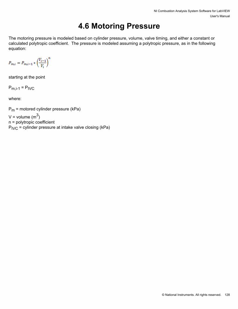
NI Combustion Analysis System Software for LabVIEWUser's Manual
© National Instruments. All rights reserved. 128
4.6 Motoring Pressure The motoring pressure is modeled based on cylinder pressure, volume, valve timing, and either a constant orcalculated polytropic coefficient. The pressure is modeled assuming a polytropic pressure, as in the followingequation:
starting at the point Pm,i-1 = PIVC where: Pm = motored cylinder pressure (kPa)
V = volume (m3)n = polytropic coefficientPIVC = cylinder pressure at intake valve closing (kPa)

NI Combustion Analysis System Software for LabVIEWUser's Manual
© National Instruments. All rights reserved. 129
4.7 Global Gas Temperature The global (bulk) gas temperature is modeled based on cylinder pressure, volume, valve timing, intake temperatureand pressure, exhaust temperature and pressure, residual gas fraction, and either a constant or calculated polytropiccoefficient.
where: T = global gas temperatureTIVC, PIVC, VIVC = bulk cylinder temperature, cylinder pressure and cylinder volume at intake valve closing,respectivelyP = cylinder pressureV = cylinder volumeTi = intake temperaturef = residual fractionTe = exhaust temperaturePi = intake pressurePe = exhaust pressuren = polytropic coefficient
1. Gatowski, J. A., Balles, E. N., Chun, K. M., Nelson, F. E., Ekchian, J. A., Heywood, J. B., 1984, “Heat Release Analysis ofEngine Pressure Data”, SAE Technical Paper Series 841359
2. Sharief, A., Chandrashekar, T. K., Antony, A. J., Samaga, B. S., 2008, “Study on Heat Transfer Correlation in IC Engines”,SAE Technical Paper Series 2008-01-1816

NI Combustion Analysis System Software for LabVIEWUser's Manual
© National Instruments. All rights reserved. 130
4.8 InjectorNI CAS Software uses a current or voltage measurement to determine the injection events. The user must specifythe type of injector used: PFI, DI, or Piezo. Injector CurrentTo measure the current drawn by the injector module, attach a current probe to the to the injector wiring.
PFI Current
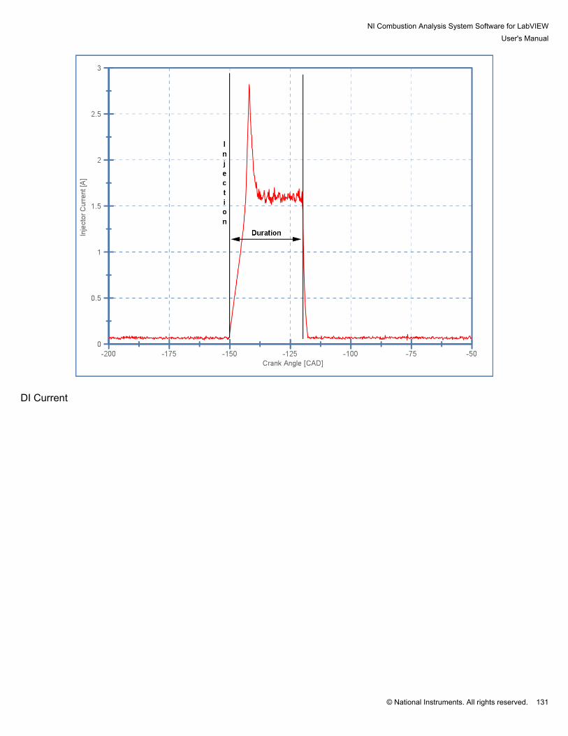
NI Combustion Analysis System Software for LabVIEWUser's Manual
© National Instruments. All rights reserved. 131
DI Current
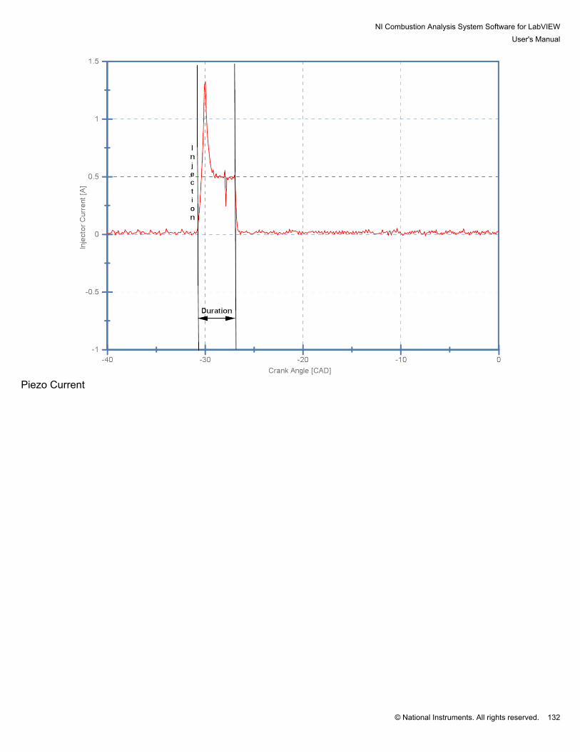
NI Combustion Analysis System Software for LabVIEWUser's Manual
© National Instruments. All rights reserved. 132
Piezo Current

NI Combustion Analysis System Software for LabVIEWUser's Manual
© National Instruments. All rights reserved. 133
Injector VoltageInjector voltages vary from battery voltage to several hundred volts. Therefore, a protective circuit is needed toprevent the high voltage from reaching the DAQ device. The operating voltage of the injectors should be verifiedbefore connecting the injector to the DAQ device. Resistor rated above the maximum operating voltage are alsorequired. Please note: Most DAQ devicess and accessories have maximum voltage limits that should be followed. Pleaserefer to your hardware documentation for details. IE. the SCB-68 has a maximum voltage of 48V listed in the user'smanual.

NI Combustion Analysis System Software for LabVIEWUser's Manual
© National Instruments. All rights reserved. 134
PFI Voltage
DI Voltage

NI Combustion Analysis System Software for LabVIEWUser's Manual
© National Instruments. All rights reserved. 135
Piezo Voltage

NI Combustion Analysis System Software for LabVIEWUser's Manual
© National Instruments. All rights reserved. 136

NI Combustion Analysis System Software for LabVIEWUser's Manual
© National Instruments. All rights reserved. 137
4.9 Heat Release The heat release rate, or dQ/dt, represents "the difference between the chemical energy or heat released bycombustion of the fuel... and the heat transfer from the system." 1 The CAS software calculates the heat release rate using several user selectable mathematical models, including:
• Single Zone• Single Zone + Heat Transfer• Single Zone Dual Transducer• Single Zone Dual Transducer + Heat Transfer• Modified Rassweiler and Withrow• Pressure Ratio
For those models including heat transfer, the following correlations are available for selection:
• Constant• Woschni 1967• Woschni 1990• Hohenberg
In the cases where heat transfer is neglected (adiabatic), the polytropic process is considered reversible andtherefore isentropic. If an ideal gas is assumed, the polytropic coefficient is constant and equal to the ratio ofspecific heats ( = n). 2 However, when heat transfer is calculated, the following polytropic correlations are availablefor selection:
• Hayes• Indolene• Propane• Custom
Note: Whenever heat transfer is being calculated, the 'Gas Temp' calculations must be enabled in the Calculationssubhost.
1. Heywood, J. B., Internal Combustion Engine Fundamentals. McGraw Hill, Inc., New York, NY. 1988.2. Russel, L. D., and Adebiyi, G. A., Classical Thermodynamics. Saunders College Publishing, Fort Worth, TX. 1993.

NI Combustion Analysis System Software for LabVIEWUser's Manual
© National Instruments. All rights reserved. 138
4.9.1 Heat Release Models
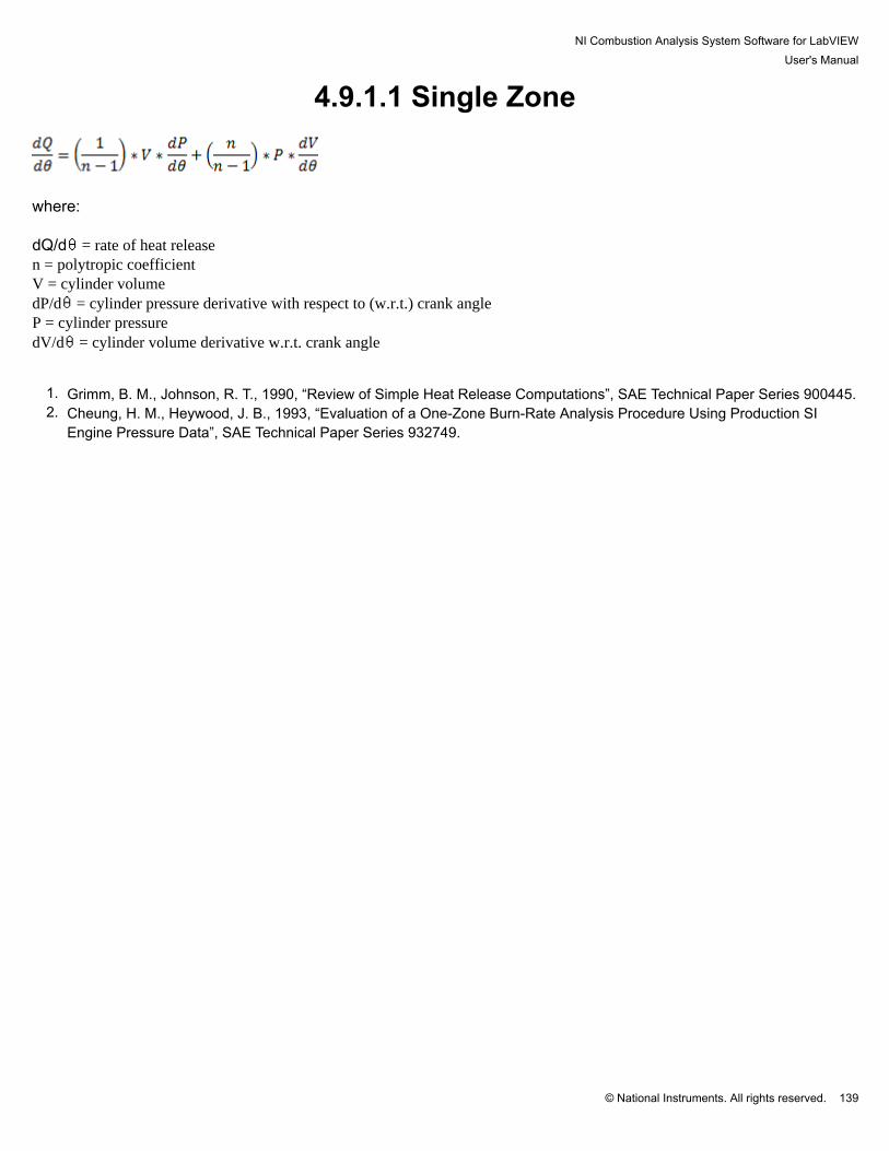
NI Combustion Analysis System Software for LabVIEWUser's Manual
© National Instruments. All rights reserved. 139
4.9.1.1 Single Zone
where: dQ/d = rate of heat releasen = polytropic coefficientV = cylinder volumedP/d = cylinder pressure derivative with respect to (w.r.t.) crank angleP = cylinder pressuredV/d = cylinder volume derivative w.r.t. crank angle
1. Grimm, B. M., Johnson, R. T., 1990, “Review of Simple Heat Release Computations”, SAE Technical Paper Series 900445.2. Cheung, H. M., Heywood, J. B., 1993, “Evaluation of a One-Zone Burn-Rate Analysis Procedure Using Production SI
Engine Pressure Data”, SAE Technical Paper Series 932749.
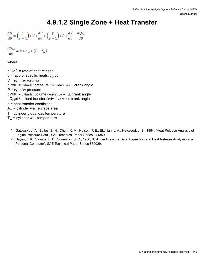
NI Combustion Analysis System Software for LabVIEWUser's Manual
© National Instruments. All rights reserved. 140
4.9.1.2 Single Zone + Heat Transfer
where: dQ/d = rate of heat releaseγ = ratio of specific heats, cp/cvV = cylinder volumedP/d = cylinder pressure derivative w.r.t. crank angleP = cylinder pressuredV/d = cylinder volume derivative w.r.t. crank angledQht/d = heat transfer derivative w.r.t. crank angleh = heat transfer coefficientAw = cylinder wall surface areaT = cylinder global gas temperatureTw = cylinder wall temperature
1. Gatowski, J. A., Balles, E. N., Chun, K. M., Nelson, F. E., Ekchian, J. A., Heywood, J. B., 1984, “Heat Release Analysis ofEngine Pressure Data”, SAE Technical Paper Series 841359.
2. Hayes, T. K., Savage, L. D., Sorenson, S. C., 1986, “Cylinder Pressure Data Acquisition and Heat Release Analysis on aPersonal Computer”, SAE Technical Paper Series 860029.

NI Combustion Analysis System Software for LabVIEWUser's Manual
© National Instruments. All rights reserved. 141
4.9.1.3 Single Zone Dual Transducer
where: dQ/d = rate of heat releasen = polytropic coefficientVmc = main chamber volume
dPmc/d = main chamber pressure derivative w.r.t. crank angleVpc = pre-chamber volume
dPpc/d = pre-chamber pressure derivative w.r.t. crank anglePmc = main chamber pressure
dVmc/d = main chamber volume derivative w.r.t. crank angle
1. Grimm, B. M., Johnson, R. T., 1990, “Review of Simple Heat Release Computations”, SAE Technical Paper Series 900445.

NI Combustion Analysis System Software for LabVIEWUser's Manual
© National Instruments. All rights reserved. 142
4.9.1.4 Single Zone Dual Transducer + Heat Transfer
where: dQ/d = rate of heat releasen = polytropic coefficientVmc = main chamber volume
dPmc/d = main chamber pressure derivative w.r.t. crank angleVpc = pre-chamber volume
dPpc/d = pre-chamber pressure derivative w.r.t. crank anglePmc = main chamber pressure
dVmc/d = main chamber volume derivative w.r.t. crank angle
dQht/d = heat transfer derivative w.r.t. crank angleh = heat transfer coefficientAw = cylinder wall surface areaT = cylinder global gas temperatureTw = cylinder wall temperature
1. Grimm, B. M., Johnson, R. T., 1990, “Review of Simple Heat Release Computations”, SAE Technical Paper Series 900445.2. Gatowski, J. A., Balles, E. N., Chun, K. M., Nelson, F. E., Ekchian, J. A., Heywood, J. B., 1984, “Heat Release Analysis of
Engine Pressure Data”, SAE Technical Paper Series 841359.

NI Combustion Analysis System Software for LabVIEWUser's Manual
© National Instruments. All rights reserved. 143
4.9.1.5 Modified Rassweiler and Withrow
where: dQ/d = rate of heat releasen = polytropic coefficientV = cylinder volumedPc/d = cylinder pressure change due to piston motion and heat release w.r.t. crank angleP = cylinder pressure
1. Grimm, B. M., Johnson, R. T., 1990, “Review of Simple Heat Release Computations”, SAE Technical Paper Series 900445.2. Rassweiler, G. M., Withrow, L., 1938, “Motion Pictures of Engine Flames Correlated with Pressure Cards”, Society of
Automotive Engineers, Paper 380139.

NI Combustion Analysis System Software for LabVIEWUser's Manual
© National Instruments. All rights reserved. 144
4.9.1.6 Pressure Ratio
where: dQ/d = rate of heat releaseP = cylinder pressurePm = motored cylinder pressureNMEP = net (indicated) mean effective pressureVd = displaced cylinder volume
d = crank angle differentialV = cylinder volumen = polytropic coefficient
1. Sellnau, M. C., Matekunas, F. A., Battiston, P. A., Chang, C. F., Lancaster, D. R., 2000, “Cylinder-Pressure-Based engineControl Using Pressure-Ratio-Management and Low-Cost Non-Intrusive Cylinder Pressure Sensors”, SAE Technical PaperSeries 2000-01-0932.

NI Combustion Analysis System Software for LabVIEWUser's Manual
© National Instruments. All rights reserved. 145
4.9.2 Heat Transfer Correlations

NI Combustion Analysis System Software for LabVIEWUser's Manual
© National Instruments. All rights reserved. 146
4.9.2.1 Constant This setting uses a constant user input for the heat transfer coefficient in units of W/m2-K.

NI Combustion Analysis System Software for LabVIEWUser's Manual
© National Instruments. All rights reserved. 147
4.9.2.2 Woschni 1967
Gas ExchangeC1 = 6.18C2 = 0 CompressionC1 = 2.28C2 = 0 Combustion and ExpansionC1 = 2.28
C2 = 3.24 x 10⁻³
where: h = heat transfer coefficient (W/m2-K)N = engine speed (RPM)B = cylinder bore (m)P = cylinder pressure (kPa)T = cylinder global gas temperature (K)w = mean cylinder gas velocity (m/s)Sp = mean piston speed (m/s)VD = displacement per cylinder (m3)
V = cylinder volume (m3)Pm = motored cylinder pressure (kPa)n = polytropic coefficientTIVC, PIVC, VIVC = bulk cylinder temperature, cylinder pressure and cylinder volume at intake valve closing,respectively
1. Heywood, J. B., Internal Combustion Engine Fundamentals. McGraw Hill, Inc., New York, NY. 1988.2. Woschni, G., 1967, “A Universally Applicable Equation for the Instantaneous Heat Transfer Coefficient in the Internal
Combustion Engine”, Society of Automotive Engineers, Paper 670931.
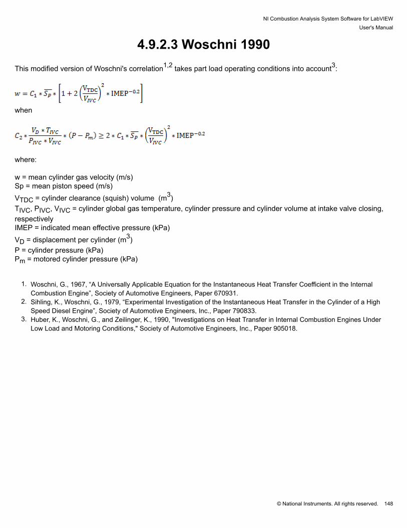
NI Combustion Analysis System Software for LabVIEWUser's Manual
© National Instruments. All rights reserved. 148
4.9.2.3 Woschni 1990 This modified version of Woschni's correlation1,2 takes part load operating conditions into account3:
when
where: w = mean cylinder gas velocity (m/s)Sp = mean piston speed (m/s)VTDC = cylinder clearance (squish) volume (m3)TIVC, PIVC, VIVC = cylinder global gas temperature, cylinder pressure and cylinder volume at intake valve closing,respectivelyIMEP = indicated mean effective pressure (kPa)VD = displacement per cylinder (m3)P = cylinder pressure (kPa)Pm = motored cylinder pressure (kPa)
1. Woschni, G., 1967, “A Universally Applicable Equation for the Instantaneous Heat Transfer Coefficient in the InternalCombustion Engine”, Society of Automotive Engineers, Paper 670931.
2. Sihling, K., Woschni, G., 1979, “Experimental Investigation of the Instantaneous Heat Transfer in the Cylinder of a HighSpeed Diesel Engine”, Society of Automotive Engineers, Inc., Paper 790833.
3. Huber, K., Woschni, G., and Zeilinger, K., 1990, "Investigations on Heat Transfer in Internal Combustion Engines UnderLow Load and Motoring Conditions," Society of Automotive Engineers, Inc., Paper 905018.

NI Combustion Analysis System Software for LabVIEWUser's Manual
© National Instruments. All rights reserved. 149
4.9.2.4 Hohenberg
where: h = heat transfer coefficient (W/m2-K)N = engine speed (RPM)V = cylinder volume (m3)P = cylinder pressure (kPa)T = cylinder global gas temperature (K)Sp = mean piston speed (m/s)
1. Hohenberg, G. F., 1979, “Advanced Approaches for Heat Transfer Calculations”, Society of Automotive Engineers, Inc.,Paper 790825.

NI Combustion Analysis System Software for LabVIEWUser's Manual
© National Instruments. All rights reserved. 150
4.9.3 Polytropic Correlation

NI Combustion Analysis System Software for LabVIEWUser's Manual
© National Instruments. All rights reserved. 151
4.9.3.1 Hayes (SAE860029)
where: γ = ratio of specific heatsT = cylinder global gas temperature (K)cp = specific heat for constant pressureR = the universal gas constant
1. Hayes, T. K., Savage, L. D., Sorenson, S. C., 1986, “Cylinder Pressure Data Acquisition and Heat Release Analysis on aPersonal Computer”, SAE Technical Paper Series 860029

NI Combustion Analysis System Software for LabVIEWUser's Manual
© National Instruments. All rights reserved. 152
4.9.3.2 Indolene (SAE841359)
where: γ = ratio of specific heatsT = cylinder global gas temperature (K)
1. Gatowski, J. A., Balles, E. N., Chun, K. M., Nelson, F. E., Ekchian, J. A., Heywood, J. B., 1984, “Heat Release Analysis ofEngine Pressure Data”, SAE Technical Paper Series 841359

NI Combustion Analysis System Software for LabVIEWUser's Manual
© National Instruments. All rights reserved. 153
4.9.3.3 Propane (SAE841359)
where: γ = ratio of specific heatsT = cylinder global gas temperature (K)
1. Gatowski, J. A., Balles, E. N., Chun, K. M., Nelson, F. E., Ekchian, J. A., Heywood, J. B., 1984, “Heat Release Analysis ofEngine Pressure Data”, SAE Technical Paper Series 841359

NI Combustion Analysis System Software for LabVIEWUser's Manual
© National Instruments. All rights reserved. 154
4.9.3.4 Custom The custom option for the polytropic correlation allows the user to input values for coefficients a and b to be used inthe following linear correlation:
where: γ = ratio of specific heatsT = cylinder global gas temperature (K)

NI Combustion Analysis System Software for LabVIEWUser's Manual
© National Instruments. All rights reserved. 155
4.9.4 Start and End of Combustion A precise definition of the start of combustion (SOC) and end of combustion (EOC) is required for accuratecalculation of the mass fraction burned (MFB) crank angle locations. The SOC and EOC are used to define awindow over which the cumulative heat release is calculated from the heat release rate (HRR) waveform. Thefollowing methods are used to define these locations: Start of combustion (SOC)
1. Constant - Defines a constant crank angle (DATDC) as the SOC.2. N Below Zero - Sets a crank angle (DATDC) to begin looking for a negative zero crossing in the HRR waveform.
After 'N' points are found past the negative zero crossing, the crossing is confirmed to be the SOC.3. Boxcar N Below Zero - Same definition of 'N Below Zero', except that a Boxcar filter of window 'N' is applied to
the HRR waveform. Also, rather than using 'N' points to confirm the crossing, the first negative zero crossing istaken as the SOC.
4. N Above Zero - Sets a crank angle (DATDC) to begin looking for the last positive zero crossing in the HRRwaveform. After 'N' points are found past the positive zero crossing, the crossing is confirmed to be the SOC.
5. Boxcar N Above Zero - Same definition of 'N Above Zero', except that a Boxcar filter of window 'N' is applied tothe HRR waveform. Also, rather than using 'N' points to confirm the crossing, the first positive zero crossing istaken as the SOC.
The following figure represents both the 'N Below Zero' and 'N Above Zero' conditions for calculating the SOC,where 1 < N < 6.
End of combustion (EOC)

NI Combustion Analysis System Software for LabVIEWUser's Manual
© National Instruments. All rights reserved. 156
1. Constant - Defines a constant crank angle (DATDC) as the EOC2. N Below Zero - Sets a crank angle (DATDC) to end looking for the first negative zero crossing in the HRR
waveform. After 'N' points are found past the negative zero crossing, the crossing is confirmed to be the EOC. If a negative zero crossing is not found, the 'End Angle' will be used as the EOC.
3. Boxcar N Below Zero - Same definition of 'N Below Zero', except that a Boxcar filter of window 'N' is applied tothe HRR waveform. Also, rather than using 'N' points to confirm the crossing, the first negative zero crossing istaken as the SOC.

NI Combustion Analysis System Software for LabVIEWUser's Manual
© National Instruments. All rights reserved. 157
4.10 Combustion Noise Combustion noise is calculated based on the power level (dB) from the cylinder pressure waveform using thefollowing steps:
1. Converting the cylinder pressure waveform from the engine-position domain to the time domain2. Converting the cylinder pressure signal from the time domain to the frequency domain using Fast Fourier
Transform (FFT)3. Converting the cylinder pressure frequency domain into a third-octave spectrum to simulate analog devices4. Filter the spectrum for human auditory attenuation using the A-weighting curve2 and for engine structure
attenuation using the SA1-7dB3,4 curve (Lucas plot).
1. Scarpati, J., Wikstrom, A., Jonsson, O., Glav, R., Handel, P., and Hjalmarsson, H., 2007, "Predication of Engine Noiseusing Parameterized Combustion Pressure Curves", SAE Technical Paper Series 2007-01-2373.
2. International Electrotechnical Commission, "Electroacoustics - Sound level meters," IEC 61672, 2003.3. Herbert, A., and Russell, M., 1982, "Measurement of Combustion Noise in Diesel Engines", Mechanical Engineering
Technology.4. Reinhart, T., 1987, "An Evaluation of the Lucas Combustion Noise Meter on Cummins 'B' Series Engines", SAE Technical
Paper Series 870952.

NI Combustion Analysis System Software for LabVIEWUser's Manual
© National Instruments. All rights reserved. 158
4.11 Misfire The misfire calculation returns a Boolean output (0 or 1). The calculation is based on one of the following misfirethreshold (kPa) comparisons:
1. Peak Pressure < Misfire Threshold2. Net Mean Effective Pressure = NMEP < Misfire Threshold3. Combustion Pressure = Cylinder Pressure - Motored Cylinder Pressure < Misfire Threshold

NI Combustion Analysis System Software for LabVIEWUser's Manual
© National Instruments. All rights reserved. 159
4.12 Cam NI CAS Software uses a digital signal with rising and falling edges to determine the cam phasing. The user mustspecify the edge count, location (CAD), and whether each edge is rising or falling. The user specified pattern iscompared with the actual pattern to determine the cam advance or retard. The user specified position is usually thedefault cam position or the position where the cam returns without power.

NI Combustion Analysis System Software for LabVIEWUser's Manual
© National Instruments. All rights reserved. 160
4.13 Synchronous Pump NI CAS Software uses a digital signal with rising and falling edges to determine the start, end, and duration ofmultiple pulses over the span of one engine cycle. The number of pulses is reported along with the start, end, andduration for each pulse.

NI Combustion Analysis System Software for LabVIEWUser's Manual
© National Instruments. All rights reserved. 161
4.14 PWM NI CAS Software uses a digital signal with rising and falling edges to determine the frequency and duty cycle of aPWM signal. The frequency is calculated using the rising edges of the signal. The duty cycle is calculated using theratio of signal high time compared to the time between rising edges. The cycle results are averaged over the entirecycle. Note: The sample rate of the system must be much greater than the PWM frequency to get accurate results.

NI Combustion Analysis System Software for LabVIEWUser's Manual
© National Instruments. All rights reserved. 162
4.15 KnockNI CAS Software uses the Bandpass, Rectify, Integrate, Compare (BRIC) knock detection method. This methodrequires the user to define calibration windows where there is little electrical and mechanical noise. The user alsomust provide cutoff frequencies for the bandpass filter (2nd order Butterworth IIR), which allow the fundamentalfrequencies of knock to pass but not background noise. The last required user input is the threshold where the rawknock intensity is considered to be knock.

NI Combustion Analysis System Software for LabVIEWUser's Manual
© National Instruments. All rights reserved. 163
4.16 SparkNI CAS Software uses a current or voltage on the low side of primary ignition coil to measure the spark event andspark dwell. Spark CurrentTo measure the current drawn by the spark module, attach a current probe to the low side of the primary ignition coil.
The signal should be similar to the following.

NI Combustion Analysis System Software for LabVIEWUser's Manual
© National Instruments. All rights reserved. 164
Spark VoltageThe low side of the primary ignition coil can reach 400V. Therefore, a protective circuit is needed to prevent the highvoltage from reaching the DAQ device. A zener diode with a breakdown voltage of 1/2 the maximum analog inputvoltage is required (10V ADC = ~5V zener diode). A resistor rated above 400V is also required. It should be sized tolimit the current flow to the zener diode (100 k and 1/4 W). Please note: Most DAQ devices and accessories have maximum voltage limits that should be followed. Pleaserefer to your hardware documentation for details. IE. the SCB-68 has a maximum voltage of 48V listed in the user'smanual.
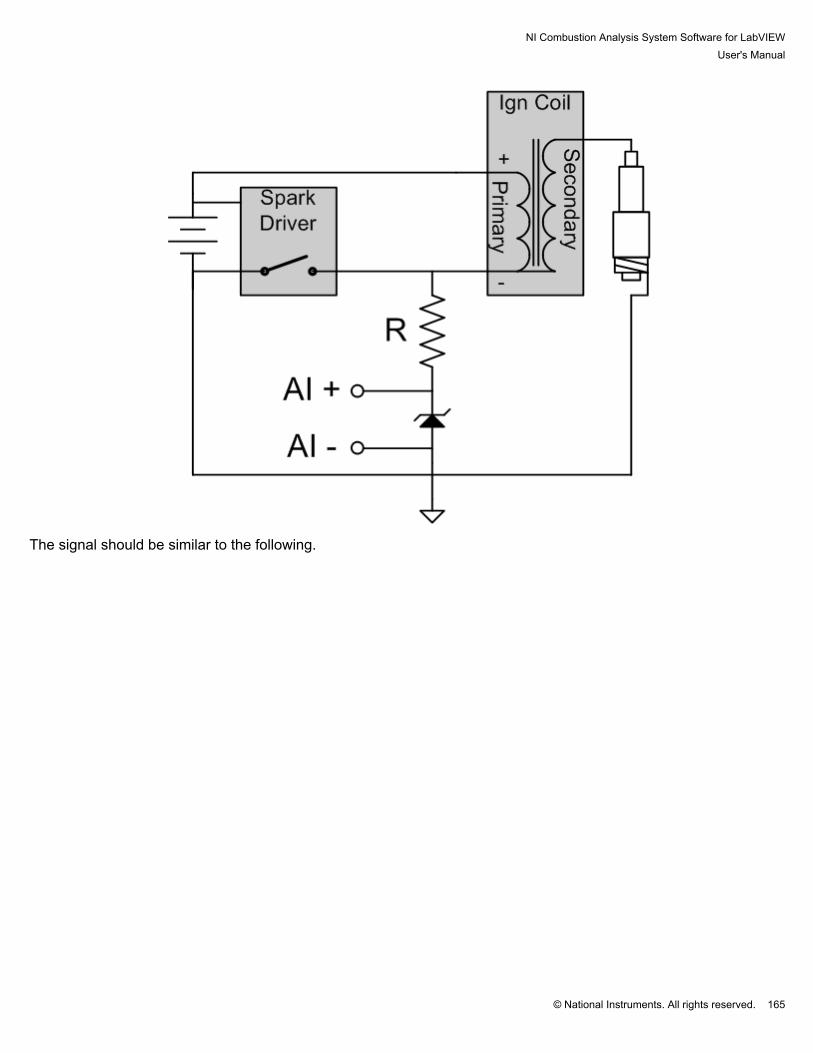
NI Combustion Analysis System Software for LabVIEWUser's Manual
© National Instruments. All rights reserved. 165
The signal should be similar to the following.

NI Combustion Analysis System Software for LabVIEWUser's Manual
© National Instruments. All rights reserved. 166

NI Combustion Analysis System Software for LabVIEWUser's Manual
© National Instruments. All rights reserved. 167
4.17 Custom User VIs While NI CAS Software incorporates many well known calculations and processing operations useful for combustionanalysis, inevitably each project is different and may require calculations not included in NI CAS Software by default. To accommodate this, NI CAS Software has the ability to execute custom user programmed VIs in three differentlocations: processing, heat release, and calculations. Processing algorithms are intended to manipulate waveforms,e.g., cylinder pressure pegging, before other calculations are performed. Custom heat release allows the user todesignate a non-standard model for heat release. Finally, the outputs of user calculations are scalar values forwhich statistics are automatically calculated. User Templates In order to ensure successful integration of a custom user VI, user VI templates must be used as a starting point forall custom user VIs. User VI templates are included with the installation of NI CAS Software in the example projectas well as the following location in the LabVIEW directory: \...\examples\Combustion Analysis\ Note: The LabVIEW development environment is required to create a custom user VI
Custom Application: Cumulative Heat Release In this application, the user desires to calculate the cumulative heat release in Joules for one cycle of combustion. Mathematically, this is done by integrating calculated heat release rate (dQ/dθ) between the defined start ofcombustion (SOC) and end of combustion (EOC), as in the following equation:
The following steps were accomplished to achieve this goal: 1. Open the template for custom user calculations in the Combustion Analysis examples folder. The block diagramshould appear as follows:

NI Combustion Analysis System Software for LabVIEWUser's Manual
© National Instruments. All rights reserved. 168
User Calculations Template
2. Use the 'Unbundle by Name' function from the 'Cluster, Class, & Variant' function palette to unpack the followinginputs:
• Cycle Waveforms \ Heat Release Rate [J/CAD]• All Setup \ Engine Geometry Setup \ Rotations Per Cycle• Engine Geometry Results \ Sample Resolution [ppr]
Unbundling calculation inputs
3. Create start and end of combustion constants in degrees after top dead center (DATDC), then convert them toarray indices using the 'Rotations Per Cycle' and 'Sample Resolution' inputs.

NI Combustion Analysis System Software for LabVIEWUser's Manual
© National Instruments. All rights reserved. 169
Defining and converting SOC and EOC to indices
Note: Waveform array indices start with '0' at 180 (2-stroke) or 360 CAD (4+ stroke) before compression TDC. Forexample, with a 3600 pulse-per-revolution encoder on a 4-stroke engine, the indices will range from 0 to 7200, with3600 being compression TDC.
4. Index an array subset from the heat release rate waveform, starting with the SOC and ending at the EOC (withduration EOC-SOC). This array subset corresponds to the period during which combustion is occuring. Using a ForLoop, this discrete subset can be integrated using shift register terminals and an add block. The result is the scalarvalue for cumulative heat release in Joules.
Indexing the heat release waveform and calculating the integral
5. Pack the scalar result and value name into a cluster using the 'Bundle by Name' function block and typedefprovided. Convert the bundle to an array of bundles and connect this to the 'User Results' indicator.

NI Combustion Analysis System Software for LabVIEWUser's Manual
© National Instruments. All rights reserved. 170
Packing outputs into an array of bundles
6. Use the 'Save As...' function to save your VI as a copy, renaming the new variant so that the template is notoverwritten. Finally, select your VI in the 'Calculations' subhost of NI CAS Software and view the result in the 'User'table.
Selecting and enabling User Calculations
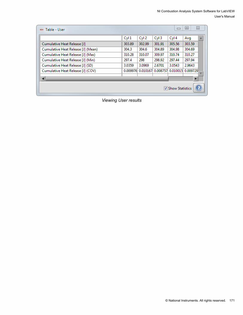
NI Combustion Analysis System Software for LabVIEWUser's Manual
© National Instruments. All rights reserved. 171
Viewing User results

NI Combustion Analysis System Software for LabVIEWUser's Manual
© National Instruments. All rights reserved. 172
5. Post Processing

NI Combustion Analysis System Software for LabVIEWUser's Manual
© National Instruments. All rights reserved. 173
5.1 NI CAS Software File Structure
Groups-Channels Use Description
Volume R-S Pre-calculated volume related waveforms
• Crank Angle R-S Cycle crank angle
• Volume R-S Cycle volume
• dVolume R-S Cycle volume derivative
• Cylinder Area R-S Cycle cylinder area
User Properties C User specified properties
File Settings C File settings
Basic Settings C Basic settings
Cam Settings C Cam settings
• 0...15 C-O Cam settings for each cylinder
Filter Settings C Filter settings
• 0...15 C-O Filter settings for each filter
Engine Geometry Setup C Engine geometry setup
Synchronous R-S-C-O Engine synchronous data
• Time R Sample timestamp
• AI0...15 R-C-N Synchronous channel
• TDC C Digital channel setup
• Data C Digital channel setup
• Reduced Resolution C Digital channel setup
• Reserved C Digital channel setup
• DI4...15 C-N Digital channel setup
• DI Data R Digital channel data in bit field
Heat Release Settings C Heat release Settings
Injection Settings C Injection Settings
Knock Settings C Knock Settings
• 0...15 C Knock settings for each cylinder
Misfire Settings C Misfire settings
Pegging Settings C Pegging settings
Gas Temperature Settings C Gas temperature settings
Separate Settings C Separate settings
TDC Offset Settings C TDC offset settings
Asynchronous R-C-O Asynchronous data
• Time R Sample timestamp

NI Combustion Analysis System Software for LabVIEWUser's Manual
© National Instruments. All rights reserved. 174
• AI0...15 R-C-N Synchronous channel
• TDC C Digital channel setup
• Data C Digital channel setup
• Reduced Resolution C Digital channel setup
• Reserved C Digital channel setup
• DI4...15 C-N Digital channel setup
• DI Data R Digital channel data in bit field
Medium Speed R-C-O Medium speed data
• Time R Sample timestamp
• AI0... R-C-N Medium speed channel
FPGA R-C-O FPGA data
• Time R Sample timestamp
• ID R Sample ID
• Data R Sample Data
• AI0... R-C-N FPGA channels
User Setup C User defined calculation setup
Cycle R Cycle properties
• Time R Cycle start timestamp
• Speed R Previous cycle speed
• Cycle R Cycle number
Slow Speed R-C-O Slow speed data
• Time R Sample timestamp
• AI0... R-C Slow speed channel
Array Data - 1... S-O Post process cycle-by-cycle waveforms foreach cylinder
• Crank Angle S Cycle crank angle
• AI0... - 0... S Cycle-by-cycle data
Synchronous Waveforms - 1... S-O Engine synchronous ensemble averages foreach cylinder
• Crank Angle S Cycle crank angle
• AI0... S-N Ensemble average waveform
Asynchronous Waveforms - 1... S-O Asynchronous ensemble averages for eachcylinder
• Crank Angle S Cycle crank angle
• AI0... S-N Ensemble average waveform
Calculation Waveforms - 1... S-O Calculated ensemble averages for eachcylinder

NI Combustion Analysis System Software for LabVIEWUser's Manual
© National Instruments. All rights reserved. 175
• Crank Angle S Cycle crank angle
• AI0... S-N Ensemble average waveform
Calculation Results - 1... S Calculated results for each cylinder
• AI0.. S-N Calculated values R = Raw DataS = Summary DataC = Configuration PropertiesO = OptionalN = Names Vary

NI Combustion Analysis System Software for LabVIEWUser's Manual
© National Instruments. All rights reserved. 176
5.2 Summary Files Summary files contain all the calculated results and ensemble averages for all the waveforms. Opening Summary Data Files1. Determine the file version and if it is a raw or summary file.2. Read configuration data.
a. General settings are found at the group level.b. Channel settings are found at the channel level.
3. Read ensemble averages for desired cylinder4. Read calculated results for desired cylinder
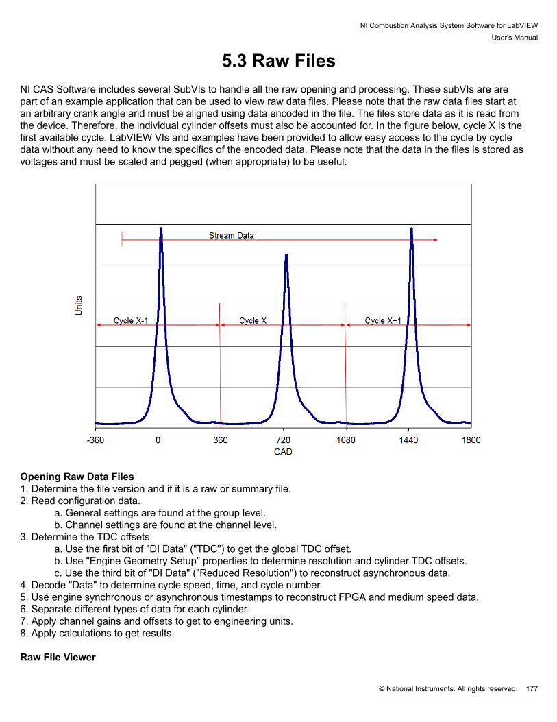
NI Combustion Analysis System Software for LabVIEWUser's Manual
© National Instruments. All rights reserved. 177
5.3 Raw Files NI CAS Software includes several SubVIs to handle all the raw opening and processing. These subVIs are arepart of an example application that can be used to view raw data files. Please note that the raw data files start atan arbitrary crank angle and must be aligned using data encoded in the file. The files store data as it is read fromthe device. Therefore, the individual cylinder offsets must also be accounted for. In the figure below, cycle X is thefirst available cycle. LabVIEW VIs and examples have been provided to allow easy access to the cycle by cycledata without any need to know the specifics of the encoded data. Please note that the data in the files is stored asvoltages and must be scaled and pegged (when appropriate) to be useful.
Opening Raw Data Files1. Determine the file version and if it is a raw or summary file.2. Read configuration data.
a. General settings are found at the group level.b. Channel settings are found at the channel level.
3. Determine the TDC offsetsa. Use the first bit of "DI Data" ("TDC") to get the global TDC offset.b. Use "Engine Geometry Setup" properties to determine resolution and cylinder TDC offsets.c. Use the third bit of "DI Data" ("Reduced Resolution") to reconstruct asynchronous data.
4. Decode "Data" to determine cycle speed, time, and cycle number.5. Use engine synchronous or asynchronous timestamps to reconstruct FPGA and medium speed data.6. Separate different types of data for each cylinder.7. Apply channel gains and offsets to get to engineering units.8. Apply calculations to get results. Raw File Viewer

NI Combustion Analysis System Software for LabVIEWUser's Manual
© National Instruments. All rights reserved. 178
1. Make sure the Activation indicator is green.2. Select a raw file to open.3. Slide the cycle selector to the desired cycle.4. Select a cylinder to display.5. Select the appropriate tab to view and change settings.

NI Combustion Analysis System Software for LabVIEWUser's Manual
© National Instruments. All rights reserved. 179
5.4 TDMS Files Opening TDMS Files in Microsoft Excel National Instruments provides a free Microsoft Excel plug-in that imports TDMS files. Importing a file creates amulti-page spreadsheet with all the data stored in the file. The first page contains a summary of all the groups andchannels. Each group has a page where each column is a channel of data. Please note that Microsoft Excel 2003 islimited to 256 columns and 65536 rows. Therefore, the custom properties (displayed in the first 2 rows on the mainpage) which contain all the calculation configuration information may need to be turned off. Raw data channels mayalso be too long and will be truncated.
Opening TDMS Files in DIAdem DIAdem is a power full tool for viewing, analyzing, and presenting data. When DIAdem is installed, double clicking ona tdms file will open it in DIAdem.

NI Combustion Analysis System Software for LabVIEWUser's Manual
© National Instruments. All rights reserved. 180
Converting TDMS Files to Other Formats TDMS files can be converted to other formats and opened in a variety of interfaces. Many resources are available onat http://www.ni.com/. The NI CAS Software comes with an application to convert a group or folder of files from theTDMS format to text files. Due to the change in how data is being stored, text files will take ~10 times the disk spaceas the TDMS files. See Batch Processing for more details.

NI Combustion Analysis System Software for LabVIEWUser's Manual
© National Instruments. All rights reserved. 181
5.5 Batch Processing Batch Process Raw Files to Summary filesNI CAS Software contains an application to process raw files to summary files. The application can process up to 8files in parallel. The user selects a source folder and the desired files to process. The summary files are placed in thespecified folder.
Batch Process TDMS files to Text filesNI CAS Software contains an application to process TDMS files to text files. The application can process up to 8 filesin parallel. The user selects a source folder and the desired files to process. The summary files are placed in thespecified folder.

NI Combustion Analysis System Software for LabVIEWUser's Manual
© National Instruments. All rights reserved. 182

NI Combustion Analysis System Software for LabVIEWUser's Manual
© National Instruments. All rights reserved. 183
6. TroubleshootingA Microsoft Windows Help file (.chm) for NI CAS Software is provided with the software download. Each windowwithin the user interface contains a Help “?” button in the bottom right corner. Pressing this button will open the Helpfile to the associated help topic page. Frequently Asked Questions (FAQs)
Q: I get an error message when I try to activate the software. What do I do? A: Refer to the Software Activation section. Q: How do I add my own calculations or results to the NI CAS Software? A: NI CAS Software provides the ability to easily integrate user calculations in three areas; Processing, Heat-Release Rate, and Calculations.
1. Processing: All of the results of the processing steps (alignment, scaling, pegging, separation) areprovided to the user calculations which can manipulate the waveform and other information before all ofthe calculations get the information.
2. Heat Release Rate: All of the results from the processing steps are provided to the user calculationswhich need to generate a heat release rate waveform. The resulting waveform is then used to calculatemass fraction burned and other heat release related parameters.
3. Calculations: All of the results from the processing steps and calculation steps are provided to the usercalculations. The user calculations provide an array of calculated results to the NI CAS Software fordisplay and saving in summary files.
NI CAS Software applications contain the ability to stream custom data from other parts of the application.
FPGA Data originates in the FPGA. Each parameter needs to be assigned an ID. All FPGA data streamsto raw data files. Only data with ID defined in the FPGA Setup are processed in real-time and saved insummary files.
Slow Speed Data is read no more than once per cycle and is saved in raw and summary data files. The toplevel NI CAS Software example contains a template showing how to write the data. The data enters NI CASSoftware through a global variable where the user defines the name, units, and value for each item.
User Properties can be added to raw and summary files. This data is captured at the beginning of a file andonly written once. NI CAS Software example applications write all CalPoints to the properties by default.
Q: How do I add a miscellaneous sensor waveform to my display? A: To display and save any signal, simply add it to the measurement setup and associate it with the appropriatecylinder. It will be displayed with all the AI or DI data for that cylinder.When do I need to align the TDC offset?A: The TDC offset must be aligned any time the encoder position is modified. This includes changing the encoder.A: The TDC offset will change as a result of changing the encoder setup parameters. These parameters may havea small effect on the relation of TDC to the encoder Z pulse. Please see the section above for more details.A: The TDC offset will change as a result of changing the encoder resolution, even if the Z pulse remainsconstant.

NI Combustion Analysis System Software for LabVIEWUser's Manual
© National Instruments. All rights reserved. 184
Q: How do I save the current configuration? A: To save the current NI CAS Software settings, use the NI SCM “Save Current Calibration as Default” (purple)or the “Save Calibration As…” (blue) buttons on the SCM interface. This saves a file to the LabVIEW default datadirectory. (This is typically under “.\My Documents\LabVIEW Data” for Microsoft Windows and "C:\ni-rt\LabVIEWData" for Real-Time.) Calibration files have a .cdl extension. These options can be found under the "Calibration"menu. Q: How do I load a saved configuration? A: To load a previous NI CAS Software calibration, copy the desired calibration file into the LabVIEW default datadirectory. (This is typically under “.\My Documents\LabVIEW Data” for Microsoft Windows and "C:\ni-rt\LabVIEWData" for Real-Time.) Use the "Calibration > Load Calibration" if live loading is enabled. Use the "Calibration > SetCalibration" and restart the NI CAS Software target if live loading is disabled. Restart the NI CAS Software targetapplication and select the appropriate file is the calibration selector is enabled. See the NI SCM User's Manual formore details. Q: Why does Microsoft Excel fail to open a TDMS files? A: The TDMS Microsoft Excel plug-in opens each property in a new column across the top of the spreadsheet.Property fields are used to store all (>255) of the configuration parameters. However, Microsoft Excel 2003 is limitedto 255 columns. Open the TDMS plug-in properties and turn off custom property imports. Q: How do I customize the user interface? A: The user interface is a standard LabVIEW VI. It may be modified with LabVIEW development tools to meetuser requirements. The file should be saved in a new location so that updating NI CAS Software installation does notoverwrite the changes.A: See the NI SCM User's Manual. Q: What font is used in the example applications? A: The example applications use Segoe UI size 15 pt as the default font. In some circumstances, a different size isused. Q: Why am I getting DAQ errors? A: Make sure that the hardware is set up properly in the Measurements and Automation Explorer and that theMeasurement Setup tab has the proper physical channel names.A: Verify that the device is not being used for other DAQ tasks.A: Verify that a single DAQ device in not used for synchronous and asynchronous measurements. Q: Why is the top of the pressure signal clipped (flat)? A: The signals will appear flat when the charge amplifier is outputting a value greater than the DAQ device or thecharge amplifier output is at its maximum.A: Reset the charge amplifier to set the zero offset pressure.A: Adjust the output gain of the charge amplifier. Q: What do I do if I am having trouble obtaining encoder sync?

NI Combustion Analysis System Software for LabVIEWUser's Manual
© National Instruments. All rights reserved. 185
A: Verify that the Cam/Crank/TDC signals are set up correctly (polarity, offsets, etc.)A: The TDC signal and the crank signals should not have rising edges at the same time. This condition can causea situation where the TDC signal and the crank signals toggle position and cause an error. (One signal may be readas true before the other.)A: Verify that the proper signals are connected to the FPGA. It may be helpful to pass the encoder signals throughthe FPGA and read them use an oscilloscope if available.A: The encoder synchronization is controlled by the engine tracking VIs. Please refer to the EPT documentationfor details on the specific flags and inputs. Q: Why are the buffers or queues overflowing? A: The buffers fill when the computer system hardware is not able to keep up with the program demands. Acombination of faster CPU, faster hard drive or additional RAM will alleviate the problem.A: The performance of the system depends on many variables including user defined functions. It may benecessary to remove some real time processing to achieve the desired performance. Q: Why are the speed and the timer not working correctly? A: Check the PFI to P0 jumpers described in the hardware setup information. That data is transferred over thesejumpers. Q: Why is the NI CAS Software running but are doing nothing? A: Please verify that you have activated the NI CAS Software. Please see Installation and Activation for details. Q: Why doesn't the Deployment Version of NI CAS Software start correctly? A: Verify that the appropriate version of DAQmx and LabVIEW Runtime are installed. The installers are availableon National Instruments website and listed at the beginning of this manual.A: Verify that NI SCM is installed and activated. Please see the NI SCM user’s manual for details on installationand activation of NI SCM.A: Verify that NI CAS Software for Deployment is activated. Check the Deployment Target Program front panel toverify that it is activated correctly.A: Manually start the application. Please see the SCM user’s manual for more details.
1. Launch the NI CAS Software for Deployment Target Program. It cam be started from LabVIEW, selectHelp > Find Examples. Search for "CAS".2. Open NI SCM3. Within NI SCM, define the Target IP address as “127.0.01” or your computer IP address.4. Within NI SCM, set the Host VI to “<Program Files>\National Instruments\CAS 2014\Host\CASRuntime.vi”.5. Within NI SCM, set the pairing file to “<Program Files>\National Instruments\CAS 2014\Host\CASRuntime.par”.6. Within NI SCM, start the Host VI.
Q: Why does the real time controller crashed without warning? A: Reboot the controller and try running the application again.A: It may be possible to exceed the total physical memory of real time system. In this case, the real time controllerwill most likely crash (real time systems do not have virtual memory). The memory should be monitored using one of

NI Combustion Analysis System Software for LabVIEWUser's Manual
© National Instruments. All rights reserved. 186
the tools available with LabVIEW. Remove some of the memory use or add more memory to the system to preventthe crashes. (Please check with National Instruments for details on upgrading memory in a real time system.)
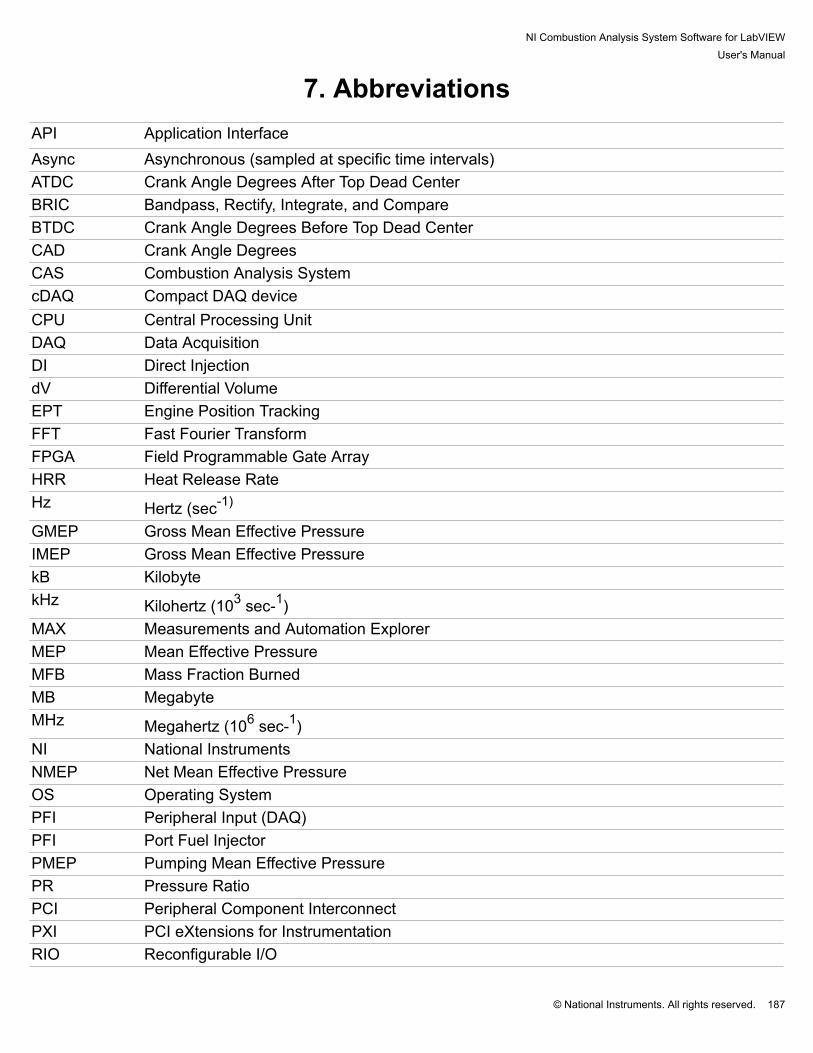
NI Combustion Analysis System Software for LabVIEWUser's Manual
© National Instruments. All rights reserved. 187
7. Abbreviations API Application InterfaceAsync Asynchronous (sampled at specific time intervals)ATDC Crank Angle Degrees After Top Dead CenterBRIC Bandpass, Rectify, Integrate, and CompareBTDC Crank Angle Degrees Before Top Dead CenterCAD Crank Angle DegreesCAS Combustion Analysis SystemcDAQ Compact DAQ deviceCPU Central Processing UnitDAQ Data AcquisitionDI Direct InjectiondV Differential VolumeEPT Engine Position TrackingFFT Fast Fourier TransformFPGA Field Programmable Gate ArrayHRR Heat Release RateHz Hertz (sec-1)
GMEP Gross Mean Effective PressureIMEP Gross Mean Effective PressurekB KilobytekHz Kilohertz (103 sec-1)MAX Measurements and Automation ExplorerMEP Mean Effective PressureMFB Mass Fraction BurnedMB MegabyteMHz Megahertz (106 sec-1)NI National InstrumentsNMEP Net Mean Effective PressureOS Operating SystemPFI Peripheral Input (DAQ)PFI Port Fuel InjectorPMEP Pumping Mean Effective PressurePR Pressure RatioPCI Peripheral Component InterconnectPXI PCI eXtensions for InstrumentationRIO Reconfigurable I/O
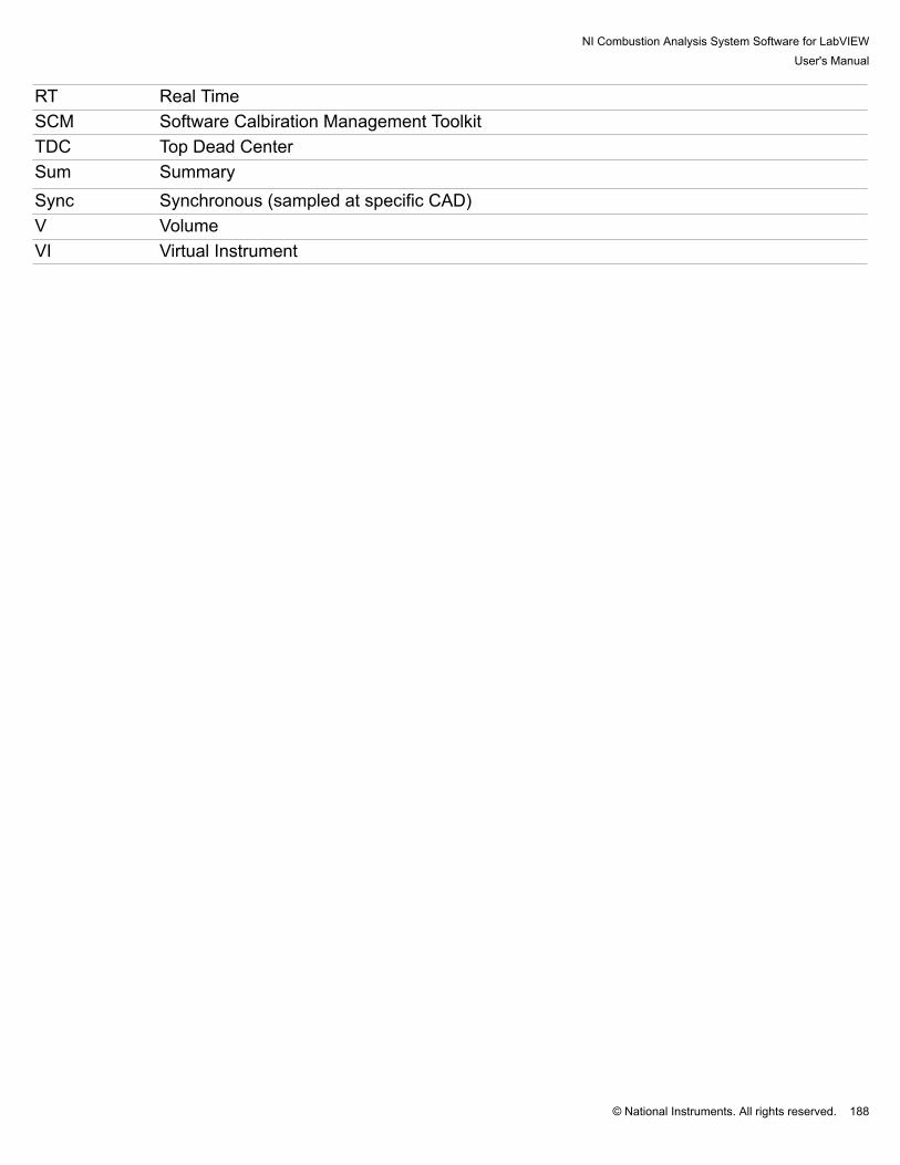
NI Combustion Analysis System Software for LabVIEWUser's Manual
© National Instruments. All rights reserved. 188
RT Real TimeSCM Software Calbiration Management ToolkitTDC Top Dead CenterSum SummarySync Synchronous (sampled at specific CAD)V VolumeVI Virtual Instrument

NI Combustion Analysis System Software for LabVIEWUser's Manual
© National Instruments. All rights reserved. 189
8. Additional Support/Feedback Contact your local NI branch office for support details or visit http://www.ni.com/support/ For additional help with getting your NI hardware and software installed and configured, visit: http://www.ni.com/gettingstarted/

NI Combustion Analysis System Software for LabVIEWUser's Manual
© National Instruments. All rights reserved. 190
9. Important Information

NI Combustion Analysis System Software for LabVIEWUser's Manual
© National Instruments. All rights reserved. 191
9.1 WarrantyRemove the following paragraph for software products. NI CAS Software is warranted against defects in materials and workmanship for a period of one year from the dateof shipment, as evidenced by receipts or other documentation. National Instruments will, at its option, repair orreplace equipment that proves to be defective during the warranty period. This warranty includes parts and labor. The media on which you receive National Instruments software are warranted not to fail to execute programminginstructions, due to defects in materials and workmanship, for a period of 90 days from date of shipment, asevidenced by receipts or other documentation. National Instruments will, at its option, repair or replace softwaremedia that do not execute programming instructions if National Instruments receives notice of such defects duringthe warranty period. National Instruments does not warrant that the operation of the software shall be uninterruptedor error free. A Return Material Authorization (RMA) number must be obtained from the factory and clearly marked on the outsideof the package before any equipment will be accepted for warranty work. National Instruments will pay the shippingcosts of returning to the owner parts which are covered by warranty. National Instruments believes that the information in this document is accurate. The document has been carefullyreviewed for technical accuracy. In the event that technical or typographical errors exist, National Instrumentsreserves the right to make changes to subsequent editions of this document without prior notice to holders ofthis edition. The reader should consult National Instruments if errors are suspected. In no event shall NationalInstruments be liable for any damages arising out of or related to this document or the information contained in it. EXCEPT AS SPECIFIED HEREIN, NATIONAL INSTRUMENTS MAKES NO WARRANTIES, EXPRESSOR IMPLIED, AND SPECIFICALLY DISCLAIMS ANY WARRANTY OF MERCHANTABILITY OR FITNESSFOR A PARTICULAR PURPOSE. CUSTOMER'S RIGHT TO RECOVER DAMAGES CAUSED BY FAULTOR NEGLIGENCE ON THE PART OF NATIONAL INSTRUMENTS SHALL BE LIMITED TO THE AMOUNTTHERETOFORE PAID BY THE CUSTOMER. NATIONAL INSTRUMENTS WILL NOT BE LIABLE FOR DAMAGESRESULTING FROM LOSS OF DATA, PROFITS, USE OF PRODUCTS, OR INCIDENTAL OR CONSEQUENTIALDAMAGES, EVEN IF ADVISED OF THE POSSIBILITY THEREOF. This limitation of the liability of NationalInstruments will apply regardless of the form of action, whether in contract or tort, including negligence. Any actionagainst National Instruments must be brought within one year after the cause of action accrues. National Instrumentsshall not be liable for any delay in performance due to causes beyond its reasonable control. The warranty providedherein does not cover damages, defects, malfunctions, or service failures caused by owner's failure to follow theNational Instruments installation, operation, or maintenance instructions; owner's modification of the product; owner'sabuse, misuse, or negligent acts; and power failure or surges, fire, flood, accident, actions of third parties, or otherevents outside reasonable control.

NI Combustion Analysis System Software for LabVIEWUser's Manual
© National Instruments. All rights reserved. 192
9.2 CopyrightUnder the copyright laws, this publication may not be reproduced or transmitted in any form, electronic ormechanical, including photocopying, recording, storing in an information retrieval system, or translating, in whole orin part, without the prior written consent of National Instruments Corporation. National Instruments respects the intellectual property of others, and we ask our users to do the same. NI software isprotected by copyright and other intellectual property laws. Where NI software may be used to reproduce software orother materials belonging to others, you may use NI software only to reproduce materials that you may reproduce inaccordance with the terms of any applicable license or other legal restriction.End-User License Agreements and Third-Party Legal Notices You can find end-user license agreements (EULAs) and third-party legal notices in the following locations: Notices are located in the <National Instruments>\_Legal Information and <National Instruments> directories. EULAs are located in the <National Instruments>\Shared\MDF\Legal\license directory. Review <National Instruments>\_Legal Information.txt for information on including legal information in installersbuilt with NI products.

NI Combustion Analysis System Software for LabVIEWUser's Manual
© National Instruments. All rights reserved. 193
9.3 TrademarksRefer to the NI Trademarks and Logo Guidelines at ni.com/trademarks for more information on National Instrumentstrademarks. Other product and company names mentioned herein are trademarks or trade names of theirrespective companies. For patents covering National Instruments products/technology, refer to the appropriatelocation: Help»Patents in your software, the patents.txt file on your media, or the National Instruments PatentNotice at ni.com/patents. You can find information about end-user license agreements (EULAs) and third-party legalnotices in the readme file for your NI product. Refer to the Export Compliance Information at ni.com/legal/export-compliance for the National Instruments global trade compliance policy and how to obtain relevant HTS codes,ECCNs, and other import/export data.

NI Combustion Analysis System Software for LabVIEWUser's Manual
© National Instruments. All rights reserved. 194
9.4 PatentsFor patents covering the National Instruments products/technology, refer to the appropriate location: Help»Patents inyour software, the patents.txt file on your media, or the National Instruments Patent Notice at ni.com/patents.
NI Combustion Analysis System Software for LabVIEWUser's Manual
© National Instruments. All rights reserved. 195
9.5 Warning Regarding Use of NI ProductsWARNING REGARDING USE OF NATIONAL INSTRUMENTS PRODUCTS (1) NATIONAL INSTRUMENTS PRODUCTS ARE NOT DESIGNED WITH COMPONENTS AND TESTING FORA LEVEL OF RELIABILITY SUITABLE FOR USE IN OR IN CONNECTION WITH SURGICAL IMPLANTS ORAS CRITICAL COMPONENTS IN ANY LIFE SUPPORT SYSTEMS WHOSE FAILURE TO PERFORM CANREASONABLY BE EXPECTED TO CAUSE SIGNIFICANT INJURY TO A HUMAN. (2) IN ANY APPLICATION, INCLUDING THE ABOVE, RELIABILITY OF OPERATION OF THE SOFTWAREPRODUCTS CAN BE IMPAIRED BY ADVERSE FACTORS, INCLUDING BUT NOT LIMITED TO FLUCTUATIONSIN ELECTRICAL POWER SUPPLY, COMPUTER HARDWARE MALFUNCTIONS, COMPUTER OPERATINGSYSTEM SOFTWARE FITNESS, FITNESS OF COMPILERS AND DEVELOPMENT SOFTWARE USED TODEVELOP AN APPLICATION, INSTALLATION ERRORS, SOFTWARE AND HARDWARE COMPATIBILITYPROBLEMS, MALFUNCTIONS OR FAILURES OF ELECTRONIC MONITORING OR CONTROL DEVICES,TRANSIENT FAILURES OF ELECTRONIC SYSTEMS (HARDWARE AND/OR SOFTWARE), UNANTICIPATEDUSES OR MISUSES, OR ERRORS ON THE PART OF THE USER OR APPLICATIONS DESIGNER (ADVERSEFACTORS SUCH AS THESE ARE HEREAFTER COLLECTIVELY TERMED "SYSTEM FAILURES"). ANYAPPLICATION WHERE A SYSTEM FAILURE WOULD CREATE A RISK OF HARM TO PROPERTY OR PERSONS(INCLUDING THE RISK OF BODILY INJURY AND DEATH) SHOULD NOT BE RELIANT SOLELY UPON ONEFORM OF ELECTRONIC SYSTEM DUE TO THE RISK OF SYSTEM FAILURE. TO AVOID DAMAGE, INJURY,OR DEATH, THE USER OR APPLICATION DESIGNER MUST TAKE REASONABLY PRUDENT STEPS TOPROTECT AGAINST SYSTEM FAILURES, INCLUDING BUT NOT LIMITED TO BACK-UP OR SHUT DOWNMECHANISMS. BECAUSE EACH END-USER SYSTEM IS CUSTOMIZED AND DIFFERS FROM NATIONALINSTRUMENTS' TESTING PLATFORMS AND BECAUSE A USER OR APPLICATION DESIGNER MAY USENATIONAL INSTRUMENTS PRODUCTS IN COMBINATION WITH OTHER PRODUCTS IN A MANNER NOTEVALUATED OR CONTEMPLATED BY NATIONAL INSTRUMENTS, THE USER OR APPLICATION DESIGNERIS ULTIMATELY RESPONSIBLE FOR VERIFYING AND VALIDATING THE SUITABILITY OF NATIONALINSTRUMENTS PRODUCTS WHENEVER NATIONAL INSTRUMENTS PRODUCTS ARE INCORPORATED IN ASYSTEM OR APPLICATION, INCLUDING, WITHOUT LIMITATION, THE APPROPRIATE DESIGN, PROCESS ANDSAFETY LEVEL OF SUCH SYSTEM OR APPLICATION.

NI Combustion Analysis System Software for LabVIEWUser's Manual
© National Instruments. All rights reserved. 196
9.6 Environmental ManagementNational Instruments is committed to designing and manufacturing products in an environmentally responsiblemanner. NI recognizes that eliminating certain hazardous substances from our products is beneficial not only to theenvironment but also to NI customers. For additional environmental information, refer to the NI and the Environment Web page at ni.com/environment. Thispage contains the environmental regulations and directives with which NI complies, as well as other environmentalinformation not included in this document.