220 A TIG WELDING MACHINE - Systematics Inc. · PDF file052011 220 A TIG WELDING MACHINE...
30
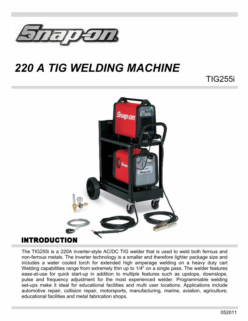
052011 220 A TIG WELDING MACHINE TIG255i INTRODUCTION The TIG255i is a 220A inverter-style AC/DC TIG welder that is used to weld both ferrous and non-ferrous metals. The inverter technology is a smaller and therefore lighter package size and includes a water cooled torch for extended high amperage welding on a heavy duty cart Welding capabilities range from extremely thin up to 1/4" on a single pass. The welder features ease-at-use for quick start-up in addition to multiple features such as upslope, downslope, pulse and frequency adjustment for the most experienced welder. Programmable welding set-ups make it ideal for educational facilities and multi user locations. Applications include automotive repair, collision repair, motorsports, manufacturing, marine, aviation, agriculture, educational facilities and metal fabrication shops.
Transcript of 220 A TIG WELDING MACHINE - Systematics Inc. · PDF file052011 220 A TIG WELDING MACHINE...
052011
220 A TIG WELDING MACHINE TIG255i
INTRODUCTION
The TIG255i is a 220A inverter-style AC/DC TIG welder that is used to weld both ferrous and non-ferrous metals. The inverter technology is a smaller and therefore lighter package size and includes a water cooled torch for extended high amperage welding on a heavy duty cart Welding capabilities range from extremely thin up to 1/4" on a single pass. The welder features ease-at-use for quick start-up in addition to multiple features such as upslope, downslope, pulse and frequency adjustment for the most experienced welder. Programmable welding set-ups make it ideal for educational facilities and multi user locations. Applications include automotive repair, collision repair, motorsports, manufacturing, marine, aviation, agriculture, educational facilities and metal fabrication shops.

1
Introduction ...............................................................................................................................Front Cover
Table of Contents.......................................................................................................................................1
Safety Information...................................................................................................................................2-3
Specifications.............................................................................................................................................4
Features.....................................................................................................................................................5
Description of Equipment......................................................................................................................6-10
Assembling the Unit/Start-up Guide....................................................................................................11-12
TIG Welding – Introduction .................................................................................................................13-18 - DC TIG Welding ............................................................................................................................15 - AC TIG Welding .......................................................................................................................16-17 - Optional Foot/Remote Amperage Control .....................................................................................18
Saving Weld Parameters .........................................................................................................................19
Spot and Stitch Welding...........................................................................................................................20
Stick Arc Welding.....................................................................................................................................21
Troubleshooting/Maintenance..................................................................................................................22
Replacement Parts .............................................................................................................................23-26 - TIG255i Parts List ....................................................................................................................23-24 - TIG255cu Parts List ......................................................................................................................25 - Standard and Optional Accessories..............................................................................................26
Wiring Diagrams .................................................................................................................................27-28 - TIG255i Wiring Diagram................................................................................................................27 - TIG255cu Wiring Diagram.............................................................................................................28
Warranty/Service and Repair ...................................................................................................................29
TABLE OF CONTENTS

2
MUST READ INSTRUCTIONS BEFORE USE Read, understand and follow all safety messages and instructions in this manual. Safety messages in this section ofthe manual contain a signal word with a three-part message and, in some instances, an icon. The signal word indicates the level of the hazard in a situation. DANGER Indicates an Imminently hazardous Situation which, if not avoided, will result in death or serious injury to the operator or bystanders. WARNING Indicates a potentially hazardous situation which, if not avoided, could result in death or serious injury to the operator or bystanders. CAUTION Indicates a potentially hazardous situation which, if not avoided, may result in moderate or minor injury to the operator or bystanders. IMPORTANT Indicates a situation which, if not avoided, may result in damage to the welding equipment. Safety messages in this section contain three different type styles. • Normal type states the hazard. • Bold type states how to avoid the hazard. • Italic type states the possible consequences of not avoiding the hazard. An icon, when present, gives a graphical description of the potential hazard.
Arc Welding
DANGER
• Electric welding or plasma cutting cause ultra
violet rays and weld spatter Bystanders will be exposed to ultraviolet rays and weld spatter. Wear welding helmet with appropriate shade lens while using electric welders or plasma cutters. Do not allow bystanders while welding or cutting. Wear safety shield and protective clothing. Ultraviolet rays will burn eyes; weld spatter can cause injury.
WARNING • Welding produces heat, sparks, hazard of
electric shock and/or hazardous vapors Wear appropriate gloves, helmets or goggles and other protective clothing. Follow all instructions and safe practices while welding or cutting. Keep bystanders away from immediate area. Byproducts of welding can cause burns or other bodily injury.
SAVE THESE INSTRUCTIONS
SAFETY INFORMATION
3
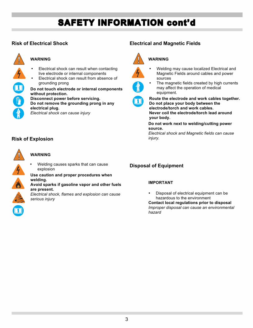
Risk of Electrical Shock
WARNING • Electrical shock can result when contacting
live electrode or internal components • Electrical shock can result from absence of
grounding prong Do not touch electrode or internal components without protection. Disconnect power before servicing. Do not remove the grounding prong in any electrical plug. Electrical shock can cause injury
Risk of Explosion
WARNING • Welding causes sparks that can cause
explosion Use caution and proper procedures when welding. Avoid sparks if gasoline vapor and other fuels are present. Electrical shock, flames and explosion can cause serious injury
Electrical and Magnetic Fields
WARNING • Welding may cause localized Electrical and
Magnetic Fields around cables and power sources
• The magnetic fields created by high currents may affect the operation of medical equipment.
Route the electrode and work cables together. Do not place your body between the electrode/torch and work cables. Never coil the electrode/torch lead around your body. Do not work next to welding/cutting power source. Electrical shock and Magnetic fields can cause injury.
Disposal of Equipment
IMPORTANT • Disposal of electrical equipment can be
hazardous to the environment Contact local regulations prior to disposal Improper disposal can cause an environmental hazard
SAFETY INFORMATION cont’d

4
By selecting TIG AC welding mode you may weld aluminum, aluminum alloys, brass and magnesium, while selecting TIG DC allows you to weld steels, stainless steel, iron and copper. This welding machine is a direct and alternating current power source built using INVERTER technology, designed to weld covered electrodes (not including cellulosic) and for TIG procedures, with contact starting and high frequency EXPLANATION OF THE TECHNICAL SPECIFICATIONS LISTED ON THE MACHINE PLATE. N°. Serial number, which must be indicated on any type of
request regarding the welding machine. Single Phase Downslope.
TIG/MMA Suitable for TIG/MMA welding. U0. Secondary open-circuit voltage (peak value) X. Duty cycle percentage. % of 10 minutes during
which the welding machine may run at a certain current without overheating.
I2. Welding current U2. Secondary voltage with current I2 U1. Rated supply voltage 1~ 50/60Hz 50- or 60-Hz single-phase power supply I1 Max Max. absorbed current at the corresponding
current I2 and voltage U2. I1 eff This is the maximum value of the actual
current absorbed, considering the duty cycle. This value usually corresponds to the capacity of the fuse (delayed type) to be used as a protection for the equipment.
IP23S Protection rating for the housing. Grade 3 as the second digit means that this machine may be stored, but it is not suitable for use out- doors in the rain, unless it is protected.
S Suitable for hazardous environments.
SPECIFICATIONS
Power Input Voltage 208/230 Volts AC Phase Single Phase Frequency 50/60 Hertz Current 30 Amps
Current 15.8 Amps Power Output Weld Current Range 5‐150 Amps Duty Cycle @ 160A 100% Duty Cycle @ 180A 60% Duty Cycle @ 220A 40%
Arc Voltage @ 220 Amps 28.8 Volts Output Control On/Off Remote Standard Foot Pedal Optional
Finger Control Optional
Pulse Frequency 0.16 ‐150Hz
Background Amp Setting AC Waveshape Balance Cleaning 1‐10
Penetration 1‐10
Frequency 50 – 150 Hz
Pulse Frequency 0.16‐500 Hz
Upslope 0‐10 Seconds
Downslope 0‐10 Seconds
Pre Gas .05‐2.5 Seconds
Post Gas 0‐30 Seconds
Gas Requirement 100% Argon
Torch Cable Length 25 Feet
Ground Cable Length 25 Feet
Gas Hose Length 4 Feet Unit Dimensions Height 45" Width 21"
Depth 36"
Unit Weight With Cart 160 lbs
Shipping Weight 180 lbs
SPECIFICATIONS
5
• Welding Process Versatility - Select between AC TIG, DC TIG or Stick Electrode welding options. • AC or DC TIG Functionality - Choose between TIG modes for non-ferrous metals using AC TIG, or for
ferrous metals using DC TIG. • Water Cooled Torch – Provides extended high amperage welding and flexibility. • Amperage Control – Fine adjustment range from 5-220 Amps to weld extremely thin materials to 1/4”
thickness in multiple passes. - Arc stability – Offers increased low amperage stability at the minimum 5 Amp current setting.
• TIG 2 or 4 stage Continuous Modes - Selectable continuous amperage output with both 2-stage setting for use with optional controls and 4-stage automatic modes.
• TIG 2 or 4 stage Pulse Modes - Selectable pulsed amperage output with both 2-stage setting for use with optional controls and 4-stage automatic modes.
• Duty Cycle – Higher duty cycles for longer weld times and current stability. • AC Balance Adjustment - Provides the ability to select from three separate functions:
- Penetration – provides a narrow bead with maximum penetration, ability to adjust eight individual selections to tailor the setting.
- Balanced – ideal ratio between width and depth of welding bead. - Cleaning – provides a wider bead and maximum material oxidation, ability to adjust eight individual
selections to tailor the setting. • Pulse Adjustment – Controls the max amperage on-time to determine the amount of heat transfer into the
material. Additionally, this feature defines the weld puddle size and allows an added level of timed puddle formation when using a filler rod.
• Background Amperage Adjustment – Amperage ranges from 10 -220 Amps AC and 5-220 Amps DC for controlled low pulse heating and minimal distortion of the parent metal when required.
• AC Frequency Adjustment – Variable 50-150 Hz adjustment between maximum arc focus, narrower heat cone displacement and broader arc focus, wider heat cone displacement.
• Upslope/Down-slope Adjustment – Provides a soft-start and finish to current ramp-up/ramp-down, adjustable from 0-10 seconds. Ideal for minimizing burn through at material edges.
• Pre-gas Flow Adjustment - Provides gas flow from 0.05-2.5 seconds before welding is started to ensure a clean weld appearance and minimal contamination.
• Post-gas Flow Adjustment – Maintains gas flow from 0-30 seconds after welding is complete to ensure a clean weld appearance and minimal contamination.
• High Frequency/Scratch Starting – Choose between HF mode for controlled arc starting or normal scratch start mode when HF is not desirable.
• Weld Parameter Recall – Capable of saving 9 individual weld setting parameters for quick recall. • RS232 Updateable – Microprocessor is updateable using the RS232 port for software enhancements. • Power Factor Correction – Minimizes power requirements due to efficient system design, requiring lower
input power supply currents. Allows for input voltage tolerances of +15% to -20% and saves electricity cost substantially.
• Cooling - Tunnel design cooling construction provides exceptional cooling efficiency while keeping electronic circuits safely out of the heated airflow.
• Cart Assembly – Heavy Duty Cart holds the Power Supply, Cooling Unit, Bottle Gas and Cables. • Warranty - Backed up by a 2-year limited warranty on all components with the exception of the TIG torch
and consumables which carries a 30-day duration.
FEATURES

6
Figure 1
DESCRIPTION OF EQUIPMENT

7
BE Main switch. 0 = OFF I = ON BG Power cable BH Gas supply fitting . BO Connector Type DB9 (RS 232). To be used for
updating the microprocessor programs. BQ Power supply socket for cooling unit. BR Pressure switch socket for cooling unit. PANEL DESCRIPTION (fig. 1). AT process key. (Left-Hand Down Arrow)
·Selection is shown by one of the glowing LEDs AX , AV , or AW .
Led AX Led AV Led AW Mode button E . (Right-Hand Down Arrow)
Selection is shown by one of the glowing LEDs F , G , H , I , L , M , N , or PP .
The TIG LEDs lighted will be two at any time, one showing the HF or contact start-up mode and the other showing the continuous or pulsed mode with 2 or 4 stages control. Every time this push-button is pressed a new selection is obtained. The LEDs glowing against the concerned symbols show your selection.
F - LED. TIG welding with arc started without high frequency.
To light the arc, press the torch trigger and touch the tungsten electrode to the work piece, then lift it. This move must be quick and decisive (0.3 sec.). Use this process when high frequency is not permitted.
L – LED TIG welding with arc started with high frequency.
To light the arc, press the torch trigger: a high voltage frequency pilot spark will light the arc.
G - LED. Continuous 2-stage TIG welding (manual).
When the torch trigger is pressed, the current begins. When the trigger is released, returns to zero. In this position, you may connect the optional pedal control accessory (TIGINVFP). H - LED. Continuous 4-stage TIG welding (automatic). This program differs from the previous one in that the arc is both started and shut off by pressing and releasing the torch trigger.
Special 4 Stages ( Automatic ) This function can be used with:
- 4 stages double level current
- pulsed 4 stages
- 4 stages double level pulsed current
It allows the crater current to be maintained (CrC) when the welding process is over until the welding torch trigger is pressed. In order to obtain this 4 stages the final crater filler function (CrA) must be ON and the crater current (tCr) must be 0.0. Welding starts when the welding torch trigger is pressed and immediately released. Starting current is the current controlled by parameter SC, the up slope follows and the welding current is reached. To stop welding the operator presses the welding torch trigger and keeps it held down, the machine then follows the slope down and reaches the crater current (CrC), this value remains active until the welding torch trigger is re- leased Fig. ( 2 ).
I - LED. 4 stages double level pulsed current (automatic).
Before lighting the arc set the two current levels: 1. First level: Press button P until led T glows and then
use knob AA to set the main power 2. Second level: press button P until led V glows and
use knob AA to set the main power. After the arc is lighted, the current begins to increase over the previously set “slope up” time (LED S on), until it reaches the value set by means of knob AA . The LED T lights and the display O shows its value. Should it be necessary to reduce the current during welding, without shutting off the arc (for instance when changing the welding material or working position, moving from horizontal to upright, etc.), press and immediately release the torch trigger, the current reaches the second set value, the LED V lights and the LED T shuts off. In order to go back to the previous main current, repeat the same torch trigger pressing and releasing action, the LED T lights while LED V shuts off. To stop welding at any time, simply hold down the torch trigger for more than 0.7 seconds, then release it; the current starts to decrease down to zero in the “slope down” time previously set (LED W on).
DESCRIPTION OF EQUIPMENT

8
During “slope down” phase, if you press and immediately release the torch trigger, the current goes back to the previously set lower level. IMPORTANT: “PRESS AND IMMEDIATELY RELEASE” refers to a maximum 0.5 sec. time.
M - LED. TIG 2 stages pulsed welding (manual)-
When the torch trigger is pressed, the current begins and when the trigger is released the current returns to zero. In this position the pedal control accessory can be connected.
N - LED. TIG-pulsed 4 stages welding (automatic)
This program differs from the previous one in that the arc is both started and shut off by pressing and releasing the torch trigger.
The Pulsed welding feature varies the weld current from the main welding current (Peak Amperage – high heat) and the second level of welding or base current (Background Amperage – low heat) levels. The TIG150i has two (2) different weld settings for the pulse features 2-stage TIG welding (manual) M – LED or 4-stage TIG welding (automatic) N - LED.
The Pulse frequency is adjustable from .16 to 250 pulses per second by selecting the mode U and setting the value with the knob AA . The duration of total time “on” between “High heat” and “Low heat” are equal.
“LED T ” – Main welding current (Peak Amperage – high heat)
This value is usually set somewhat higher than it would be set for a non-pulsed weld.
“LED V ” – Second level of welding or base current (Background Amperage – low heat)
This of course would be set lower than Main welding current. This value cannot be higher than the Main welding current. Once the base current V is set (a percentage in respect to the main current is established), so this value will change automatically when increasing or decreasing the Main current T .
“LED U ” – Pulse frequency (Pulses per Second . 16 – 250 HZ) Is the number of times per second that the welding current achieves main welding current (Peak Amperage – high heat).
Some of the advantages: • Good Penetration with less heat input to material “burn
through”. • Less distortion. • Good control of the pool when welding out of position. • Ease of welding thin materials. • Ease of welding materials of dissimilar thickness. • Helps weld training. • Smaller bead profile. • Smaller heat-affected zone.
PP - LED. TIG- pulsed 4 stages double level welding (automatic). The welding process mode is the same as the one de- scribed for led I. Once the first level peak currents are set, the ratio between them will be kept in the second level as well. *Adjust the “pre-gas” LED AL
AA - KNOB Adjusts the welding current. (LED – T ) Also, in combination with the push-button, P you may:
- adjust the second level of current LED V - adjust the "slope up" LED S - adjust the "slope down" LED W - adjust the pulse frequency LED AE - adjust the post gas LED X - adjust the current frequency in AC welding LED Q - adjust the wave balance in AC welding LED R
U – Display Upper Shows:
1. In MMA the open-circuit voltage and during welding the
load voltage. 2. In TIG continuous, without pressing the torch trigger, the
abbreviation PL (free program). In TIG continuous, when pressing the welding torch trigger, but without welding, the open-circuit voltage. In TIG continuous when pressing the torch trigger, but while welding, the load voltage.
3. Displays all abbreviations selected by means of button P . 4. Displays all the abbreviations of the service functions
menu. 5. Abbreviation “OPn“ flashing when the thermostat is on. 6. During the selection of free or saved programs
abbreviations PL…P01…P09.
DESCRIPTION OF EQUIPMENT cont’d

9
O – Display Lower Shows:
1. In open-circuit mode the reset current 2. In load conditions, the welding current and its levels. 3. In TIG-pulsed, load mode, the currents changing
from one level to the other. 4. Shows all sizes and the value of the second
functions menu. 5. Shows all sizes and values of the service function
menu. 6. Displays all values including current amperage
selected by means of button P
AQ - SELECTOR SWITCH (Special) Selects and saves programs. The welding machine can save nine welding pro-
grams P01…..P09, and call them up using this button. The work program PL is also available. Selection If this button is briefly pressed the display U shows the number of the program following the one being used. If it has not been saved the message will flash, otherwise it will remain steady. Saving (see par.3.6) Once the program has been selected, if the button is pressed for more than 3 seconds, data are saved. As confirmation, the program number on the display U will stop flashing.
P – SELECTOR SWITCH (Right Hand Arrow) When this button is pressed, the LEDs light in succession:
Important! Only those LEDs that refer to the chosen welding mode will light; i.e. in TIG-continuous led Q that re- presents the pulse frequency will not glow. Each led shows the parameter that can be set by means of knob AA during the time when the LED is glowing. 5 seconds after the last change the concerned led shuts off and the main welding current is shown and the corresponding LED T glows.
LEDS THAT MAY BE SELECTED ONLY IN TIG DC (DI- RECT CURRENT OR TIG AC WELDING (ALTERNATING CURRENT)) :
AL - Pre-gas Led Setting 0.05 to 2.5 seconds. Gas deli- very time before welding starts. Pre-gas is used to purge the weld zone and aids in eliminating troublesome arc starts.
S - LED Slope up. This is the time in which the current, starting from the minimum, reaches the set current value. (0-10 sec.)
Slope Up can be used to assist in preheating cold material prior to depositing filler material, or to ensure a soft start on higher amperage settings.
T - LED Main welding current. (10-130A in MMA and 5-150A in TIG) V - LED Second level of welding or base current. This current is always a percentage of the main. Pulsed 2-stage or Pulsed 4-stage only - Use the Second level of welding or base current to set the low current pulse of the weld amperage, which cools the weld puddle and affects overall heat input. This current is always a percentage of main current. AE - LED Pulse frequency (0.16-250 Hz) The peak and base times are equal. These pulses and the base current level -V- between them (called the Second level of welding ) alternately heat and cool the molten weld puddle. The combined effect gives better control of penetration, bead width, undercutting, and heat input W - LED Slope down. This is the time in which the cur- rent reaches the minimum value and the arc. Slope Down should be used while welding materials that are crack sensitive, and/or to eliminate the crater at the end of the weld.
X - LED Post gas. Adjusts the time gas flows after welding ends. (0-30 sec.) Post Gas is required to cool the tungsten rod and weld puddle, and to prevent contamination of tungsten and weld. Increase post gas time if tungsten or welds have a dark appearance.
DESCRIPTION OF EQUIPMENT cont’d

10
LEDS THAT MAY BE SELECTED ONLY IN TIG AC (ALTERNATING CURRENT) WELDING MODE:
AO Start LED Sets the “hot start” level to maximize TIC AC ignitions for each electrode diameter
When this led lights the display O will display a digital value referred to the electrode diameters and the operator may use the knob AA to set the diameter being used and obtain a good start immediately. Range from 0.040” to 5/32”.
Hz Q LED Sets the frequency of the alternating current Range from 50 to 150 Hz.
Current frequency in AC welding (50 - 150 Hz). Current Frequency Control is enabled only in AC TIG. Use this control to set the AC frequency (cycles per second). Current frequency controls bead width and directional control. As AC frequency decreases, weld bead/puddle gets wider. As AC frequency increases, weld bead/puddle becomes narrower and the arc becomes more focused. Travel speed can increase as frequency increases.
LED R - Wave balance setting Sets the percentage of the negative semi- wave PEn (penetration ) by means of knob
AA ; the value may change from 1 to 10. Sets the percentage of the positive semi-wave CLn (cleaning ) by means of knob AA ; the value may change from 1 to 10. The recommended setting value is 0.
The Wave Balance R feature makes it possible to vary the half cycles of the square wave when working in TIG AC when welding aluminum alloys. The point where the two half-waves meet is zero. The TIG150i offers 3 positions, Balanced, Cleaning and Penetration. Penetration (electrode negative) – is when the Wave Balance R is set clockwise from the “0” position with non-flashing numbers between“1 - 8” on the display Z . This is set to produce the more time at electrode negative and the minimum time at electrode positive.
This adds the following benefits: • Can use higher currents with smaller electrodes. • Increased penetration at a given amperage and
travel speed. • Use of smaller gas cup and reduced shielding gas
flow rate. • Reduced heat input with smaller heat effected zone
and less distortion.
Balanced (zero) – is when the Wave Balance R is set to “0” position on the display Z . This position is set to produce equal amounts of time electrode negative (penetration) and electrode positive ). This will give you less current absorption, reduced electrode consumption and an ideal ratio between the width and depth of the welding bead.
Cleaning (electrode positive) – is when the Wave Balance R is set counter-clockwise from the “0” position flashing numbers between “1 - 8” on the display Z . This is set to produce more time at electrode positive and the minimum time at electrode negative. This adds the following benefits: • Removes more surface oxides from the plate but
reduces electrode life.
Y LED LED that shows the correct operation of
the device which reduces risks of electric shock.
BC - 10-PIN CONNECTOR The following remote controls are connected to this connector: a) foot control or on/off button. b) torch with start button. c) torch with variable amperage device.
General Notes Make sure the insulation of the cables, electrode clamps, sockets and plugs are intact, and that the size and length of the welding cables are compatible with the current used.
BA - Negative output Plug the TIG torch in terminal here.
BB - Positive output Plug the “ground” terminal (+).cable in here.
BD - 1/4 GAS OUTLET FITTING Used to connect TIG welding torch gas hose.
DESCRIPTION OF EQUIPMENT cont’d
11
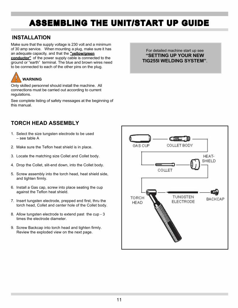
INSTALLATION Make sure that the supply voltage is 230 volt and a minimum of 30 amp service. When mounting a plug, make sure it has an adequate capacity, and that the "yellow/green conductor" of the power supply cable is connected to the ground or “earth” terminal. The blue and brown wires need to be connected to each of the other pins on the plug. WARNING Only skilled personnel should install the machine. All connections must be carried out according to current regulations. See complete listing of safety messages at the beginning of this manual. TORCH HEAD ASSEMBLY 1. Select the size tungsten electrode to be used
– see table A 2. Make sure the Teflon heat shield is in place. 3. Locate the matching size Collet and Collet body. 4. Drop the Collet, slit-end down, into the Collet body. 5. Screw assembly into the torch head, heat shield side,
and tighten firmly. 6. Install a Gas cap, screw into place seating the cup
against the Teflon heat shield. 7. Insert tungsten electrode, prepped end first, thru the
torch head, Collet and center hole of the Collet body. 8. Allow tungsten electrode to extend past the cup - 3
times the electrode diameter. 9. Screw Backcap into torch head and tighten firmly.
Review the exploded view on the next page.
ASSEMBLING THE UNIT/START UP GUIDE
For detailed machine start up see “SETTING UP YOUR NEW
TIG255I WELDING SYSTEM”.

12
COOLING UNIT This equipment is an independent cooling unit designed to cool the torches used in TIG welding systems, Art.338. EXPLANATION OF TECHNICAL SPECIFICATIONS This machine is manufactured according to the following international standards: IEC 60974.1 - IEC 60974.10 CL. A. N° Serial number that must always be indicated
on any type of request. U1 Rated supply voltage. 1x230V Single-phase power supply. 50/60 Hz Frequency. I1 max Maximum absorbed current. P max Maximum pressure. P(1l/min) Refrigerant power measured at 1l/min. IP23S Housing protection rating.
Grade 3 as the second digit means that this equipment may be stored, but it is not suitable for use outdoors in the rain, unless it is protected
DESCRIPTION OF PROTECTIVE DEVICES "Refrigerant pressure" protection This protection consists of a pressure switch inserted in the refrigerant delivery circuit, which controls a microswitch.
NOTE: To use this protection the connector I must be inserted in the socket provided C on the power source.
DESCRIPTION OF THE EQUIPMENT A ON/OFF switch (I/0). 0 = OFF I = ON B Fuse holder. C Power cord. Must be connected to the BQ socket on the
power source. D Connector that must be connected to the socket BR on
the power source. E Tank cap. F Liquid level control slot. G Cold water outlet. (PRESSURE) H Hot water inlet. (RETURN)
ASSEMBLING THE UNIT/START UP GUIDE cont’d

13
TIG WELDING – GENERAL By selecting AT welding mode you may weld aluminum, aluminum alloys, brass and magnesium, while selecting TIG DC allows you to weld steels, stainless steel, iron and copper.
1. Connect the earth (work) cable connector to the positive pole (+) (BB) of the welding machine, and the clamp to the work piece as close as possible to the welding point, making sure there is good electrical contact.
2. Connect the power connector of the TIG torch to the negative pole (-) (BA) of the welding machine.
3. Connect the foot pedal or on/off switch control plug to the welding machine connector AA.
4. Connect the torch gas hose fitting to the gas outlet fitting BD on the machine, and the gas hose from the cylinder pressure regulator to the gas fitting AG on the rear panel.
BE Switch. Turns the machine on and off. 0 = Off l = On BR Cooling unit pressure socket BQ Cooling unit power supply socket
BH - gas inlet fitting
DANGER Do not touch live parts and output terminals while the machine is powered. Read complete listing of safety messages at the beginning of this manual.
1. The first time the machine is turned on, select the
process and mode using the push-buttons AT and E , and the welding parameters by means of the key P and the knob AA .
2. The type and diameter of the electrode to be used must be selected according to table A:
TABLE AAC (frequency 50/60Hz) Inches/mm DC
Pos. Max Penetration Pos. Balanced zero Pos. Max Cleaning Electrode Type
. Tungsten
Thorium 2% Red
Tungsten Pure Green
Tungsten Zr 0,8% White
Tungsten Pure Green
Tungsten Zr 0,8% White
Tungsten Pure Green
Tungsten Zr 0,8% White
1/16in 1.6mm 70A – 150A 50A – 100A 70A – 150A 30A – 60A 50A – 80A 20A – 40A 30A – 60A 3/32in 2.4mm 150A – 250A 100A – 160A 140A – 235A 60A – 120A 80A – 140A 40A – 100A 60A – 120A
1/8in 3.2mm 200A – 350A 150A – 210A 225A – 325A 80A – 160A 100A – 180A 60A – 140A 80A – 160A 5/32in 4mm 300A – 400A 200A – 275A 300A – 400A 100A – 240A 150A – 280A 80A – 200A 150A – 250A
TIG WELDING - INTRODUCTION

14
TIG WELDING – INTRODUCTION cont’d
3. The flow of inert gas must be set to a value of 20-25 CFH. If you are using gas-lens type accessories, the gas throughput may be reduced.
4. The diameter of the ceramic nozzle must be 4 to 6 times the diameter of the electrode
5. Use D.I.N. 10 protective glasses for up to 75A, and D.I.N. 11 from 75 A up.

15
TIG Welding DC Basic Setup • With High Frequency Start • Using the On/Off Switch
Push the procedure selector switch AT. This push-button selects the welding procedure (MMA or TIG). When selected, one of the following LEDs lights: AW , AX , or AV Push the button until the TIG DC LED lights .
Then push the Mode Key E (Right Hand Down Arrow). When selected, one of the following LEDs lights: F,G,H,L,M,N. Continue to push the button until the L LED lights along with the G LED.
L - LED. TIG welding with arc started with high frequency.
G LED. Continuous 2-stage TIG welding (manual).
P - SELECTOR (Right Arrow) When this button is pushed, the following LEDs light in succession:
S - LED Slope up. This is the time in which the current, starting from the minimum, reaches the set current value. (0-10 sec.)
AA – Knob Adjusts the slope up time while watching the O display.
O – Display Displays the settings selected. Set the slope up to “0” seconds.
Push the P – Selector (Right Arrow) until the T – LED main welding current display lights.
.
Turn the AA knob while watching the O display.
O DISPLAY Adjust the display to the required main welding amperage. Rule of Thumb: “1 amp per .001 of plate thickness. (.125 =
~125 amps)
Guide For Setting TIG255i TIG Welder Note: Settings are approximate and may vary. Adjust for best results.
MATERIAL Polarity Amps Hz. THICKNESS
Steel 25 24 Ga.(.024")
Chrome Moly 30 22 Ga.(.030")
Stainless Steel 40 20 Ga.(.036")
Cast Iron 50 18 Ga.(.048")
Brass 60 16 Ga.(.060")
Nickel 75 14 Ga.(.075")
Copper 105 12 Ga.(.105")
125 1/8" (.125")
150 5/32" (.156")
180 3/16" (.1875")
220 7/32" (.21875")
DC
220 1/4" (.250")
** May require multiple passes.
Push the P – Selector (Right Arrow) until the W – LED main welding current display lights.
W - LED Slope down. This is the time in which the current reaches the minimum and the arc shuts off. (0-10 seconds). Turn the AA -Knob watching the O - Display.
Set the slope down to “0” seconds.
Push the P – Selector (Right Arrow) until the X – LED post gas display lights.
Post Gas Adjusts the time gas flows after the welding ends. ( 0-30 seconds) Turn the AA - Knob watching the O - Display.
Set the post gas to “10” seconds.
Basic TIG DC Setup is Complete.
DC TIG WELDING

16
TIG AC Welding Mode Basic Setup • With High Frequency Start • Using On/Off Button
Push the procedure selector switch (Left Hand Down Arrow). This push-button selects the welding procedure (MMA of TIG). When selected, one of the following LEDs lights: B , C , or D
Push the button until the TIG AC LED lights .
Then push the Mode Key E (Right Hand Down Arrow).
When pressing mode key E , the No High Frequency LED F will light first. Continuing to press the E button will cycle through LED lights G , H , L , M , N and PP while LED F stays lit. Pushing the mode button E again will light up the L LED. Continuing to push the button will cycle though LED lights G , H , L , M , N and PP while LED L stays lit. Cycle until the G LED lights.
L - LED. TIG welding with arc started with high frequency.
G LED. Continuous 2-stage TIG welding (manual).
Push the P – Selector (Right Arrow) until the Q – LED current frequency display lights.
Current frequency in AC welding mode. Can be adjusted from 50 – 150 Hz. Turn the AA - Knob watching the Z - Display.
Set the current frequency to “60” Hz.
Push the P – Selector (Right Arrow) until the R – LED wave balance display lights.
R - LED Wave balance in AC welding. There are three possible settings, balance = 0; Cleaning from 1-8, Penetration from 1-8. Turn the AA - Knob watching the Z - Display.
Set the wave balance to the “0” position.
Push the P – Selector (Right Arrow) until the O – LED electrode diameter display lights.
Displays the electrode diameter. The choice of electrode diameter ranges from 1mm to 4mm. Turn the AA - Knob watching the Z - Display.
Set the electrode diameter to the size recommended in Table “A”. EX.(3/32” = 2.4 mm).
Push the P – Selector (Right Arrow) until the S – LED slope up display lights.
S - LED Slope up. This is the time in which the current, starting from the minimum, reaches the set current value. (0-10 sec.)
AC TIG WELDING

17
Turn the AA -Knob watching the O - Display.
Set the slope up to “0” seconds.
Push the P – Selector (Right Arrow) until the T – LED main welding current display lights.
(10-180A in MMA and 5-220A in TIG)
Turn the AA knob while watching the O display.
O DISPLAY Adjust the display to the required main welding amperage. Rule of Thumb: “1 amp per .001 of plate thickness.
(.125 = ~125 amps)
Use the following as a guide for setting up the amperage:
Guide For Setting TIG255i TIG Welder Note: Settings are approximate and may vary. Adjust for best results.
Aluminum 25 60 24 Ga.(.024")
Magnesium 30 60 22 Ga.(.030")
40 60 20 Ga.(.036")
50 60 18 Ga.(.048")
60 60 16 Ga.(.060")
75 60 14 Ga.(.075")
105 60 12 Ga.(.105")
125 60 1/8"
150 60 5/32" (.156") 180 60 3/16" (.1875") 220 60 7/32" (.21875")
AC
220 60 1/4" (.250")
** May require multiple passes.
Push the P – Selector (Right Arrow) until the W – LED slope down display lights.
W - LED Slope down. This is the time in which the current reaches the minimum and the arc shuts off. (0-10 seconds). Turn the AA - Knob watching the O - Display.
Set the slope down to “0” seconds.
Push the P – Selector (Right Arrow) until the X – LED post gas display lights.
Post Gas Adjusts the time gas flows after the welding ends. ( 0-30 seconds) Turn the AA - Knob watching the O - Display.
Set the post gas to “10” seconds. Basic TIG AC Setup is Complete
AC TIG WELDING cont’d
**

18
How to Setup the Optional Variable Amperage Foot Pedal or Remote Finger Amp Control (RAD).
• Using High Frequency Start • TIG AC Mode
The Foot Pedal allows the welder to remotely control the amperage from 5 amps minimum to 220 amps maximum shown on the LED U display.
Install the Foot Pedal or RAD control plug in the BC receptacle.
Push the procedure selector switch (Left Hand Down Arrow). This push-button selects the welding procedure (MMA or TIG). When selected, one of the following LEDs lights: AW , AX , or AV
Push the button until the TIG AV LED lights .
Then push the Mode Key E (Right Hand Down Arrow).
When selected, one of the following LEDs lights: F,G,H,L,M,N. Continue to push the button until the L LED lights along with the G LED.
L - LED. TIG welding with arc started with high frequency. ---NOT AVAILABLE IN THE MMA MODE
G LED. Continuous 2-stage TIG welding (manual).
Push the P – Selector (Right Arrow) until the U – LED main welding current display lights.
(10-180A in MMA and 5-220A in TIG)
Activate the foot pedal or RAD to the maximum (pedal or slider fully depressed) position. While holding down the pedal to maximum,
turn the AA knob while watching the U display.
U DISPLAY Adjust the amperage to the approximate current that is required using the basic rule of thumb “one amp per thousandths of material thickness. Ex. 1/8” inch = .125 thousands so set the amps to ~125.
Push down on the pedal or slide the RAD.
The gas should purge. High frequency should activate. Amperage on the display Z should range from
5 to 125 amps.
NOW BEGIN TO WELD.
OPTIONAL FOOT PEDAL/ REMOTE AMPERAGE CONTROL
19
SAVING WELD PARAMETERS
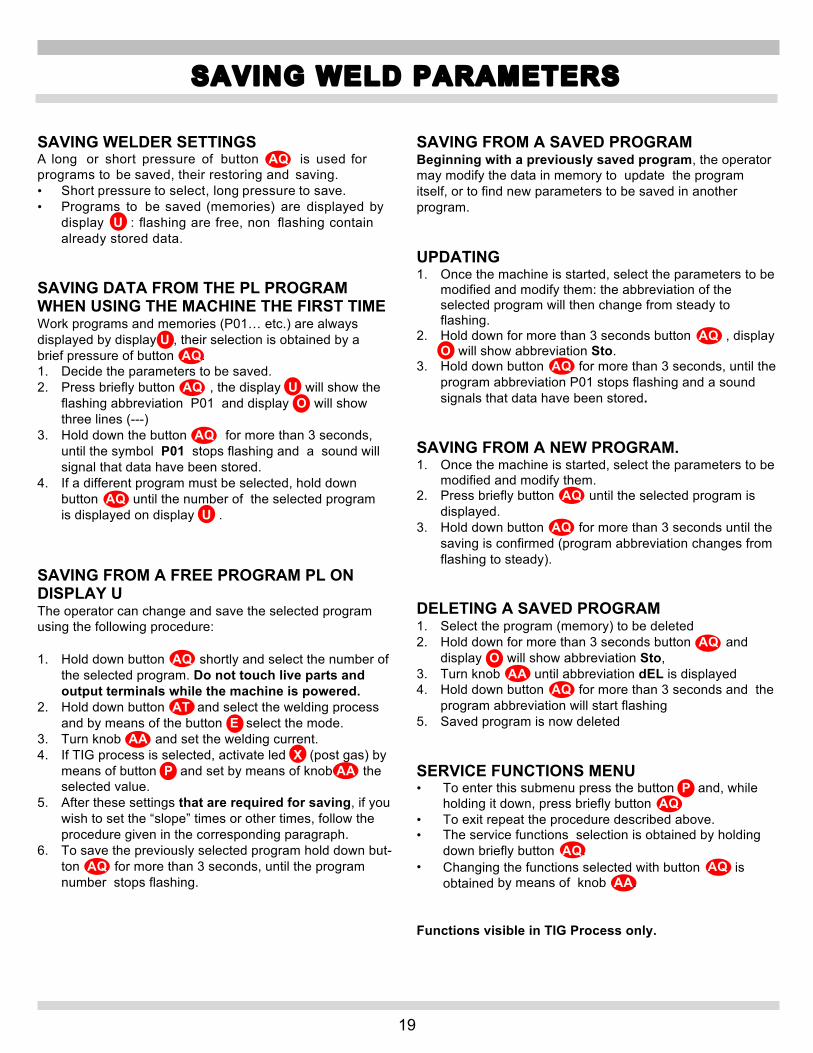
SAVING WELDER SETTINGS A long or short pressure of button AQ is used for programs to be saved, their restoring and saving. • Short pressure to select, long pressure to save. • Programs to be saved (memories) are displayed by
display U : flashing are free, non flashing contain already stored data.
SAVING DATA FROM THE PL PROGRAM WHEN USING THE MACHINE THE FIRST TIME Work programs and memories (P01… etc.) are always displayed by display U , their selection is obtained by a brief pressure of button AQ. 1. Decide the parameters to be saved. 2. Press briefly button AQ , the display U will show the
flashing abbreviation P01 and display O will show three lines (---)
3. Hold down the button AQ for more than 3 seconds, until the symbol P01 stops flashing and a sound will signal that data have been stored.
4. If a different program must be selected, hold down button AQ until the number of the selected program is displayed on display U .
SAVING FROM A FREE PROGRAM PL ON DISPLAY U The operator can change and save the selected program using the following procedure: 1. Hold down button AQ shortly and select the number of
the selected program. Do not touch live parts and output terminals while the machine is powered.
2. Hold down button AT and select the welding process and by means of the button E select the mode.
3. Turn knob AA and set the welding current. 4. If TIG process is selected, activate led X (post gas) by
means of button P and set by means of knob AA the selected value.
5. After these settings that are required for saving, if you wish to set the “slope” times or other times, follow the procedure given in the corresponding paragraph.
6. To save the previously selected program hold down but- ton AQ for more than 3 seconds, until the program number stops flashing.
SAVING FROM A SAVED PROGRAM Beginning with a previously saved program, the operator may modify the data in memory to update the program itself, or to find new parameters to be saved in another program. UPDATING 1. Once the machine is started, select the parameters to be
modified and modify them: the abbreviation of the selected program will then change from steady to flashing.
2. Hold down for more than 3 seconds button AQ , display O will show abbreviation Sto.
3. Hold down button AQ for more than 3 seconds, until the program abbreviation P01 stops flashing and a sound signals that data have been stored.
SAVING FROM A NEW PROGRAM. 1. Once the machine is started, select the parameters to be
modified and modify them. 2. Press briefly button AQ until the selected program is
displayed. 3. Hold down button AQ for more than 3 seconds until the
saving is confirmed (program abbreviation changes from flashing to steady).
DELETING A SAVED PROGRAM 1. Select the program (memory) to be deleted 2. Hold down for more than 3 seconds button AQ and
display O will show abbreviation Sto, 3. Turn knob AA until abbreviation dEL is displayed 4. Hold down button AQ for more than 3 seconds and the
program abbreviation will start flashing 5. Saved program is now deleted SERVICE FUNCTIONS MENU • To enter this submenu press the button P and, while
holding it down, press briefly button AQ • To exit repeat the procedure described above. • The service functions selection is obtained by holding
down briefly button AQ. • Changing the functions selected with button AQ is
obtained by means of knob AA. Functions visible in TIG Process only.

20
SPOT AND STITCH WELDING
SP SPOT AND STITCH WELDING Is activated in two stages welding (led G ) or 4 stages (LED H ) when the high frequency start-up is selected (LED L ). 1. Select abbreviation SP (spot) on display U by means of
button AQ , display O shows abbreviation OFF 2. By means of knob AA set ON to activate the function. 3. Press briefly button AQ to select abbreviation tSP. tSP ( Spot time) Display U shows the abbreviation SP, display O shows 1 sec. time. 1. By means of knob AA set the desired time range from
0.1 to 25 seconds. 2. If you want to set jog (welding with automatic interval)
press briefly button AQ and select abbreviation tin. tin (interval time) Display O will show abbreviation OFF. 1. Turn knob AA to select the interval time (range from 0,1
to 25 sec.). PDU (DUTY CYCLE PULSED active in pulsed mode only) • This is the duration of the highest selected current in
pulsed mode. It is expressed as a percentage of the time against the Fdp frequency (default 50%).
• Range: minimum 10% maximum 90%. SC (START-UP CURRENT) • Always active in all TIG processes. • Start current level where the welding process begins. • Especially used for AC starts-up with big electrodes and
slope up. • Sets the pedal minimum level. Default 25%. • Range: minimum 1% - maximum 100%
CRA (FINAL CRATER FILLER). 1. Select abbreviation CrA on display U by means of
button AQ , display O shows abbreviation OFF 2. By means of knob AA set ON to activate the function. 3. Press briefly button AQ to select abbreviation CrC. CrC (Carter current) This current is a percentage of the welding current and the process final current. • Default 50% • Range: minimum 10% - maximum 100% tCr (Carter current time) Crater current time duration. • Default 0.5 sec. • Range: minimum 0.0 sec. - maximum 30 sec. Functions visible in MMA process only. HS (PERCENTAGE OF HOT-START CURRENT) It is an overvoltage used to improve start-up. • Default 50% • Range: minimum 0% - maximum 100% HS (DURATION OF HOT-START CURRENT) • Default 0.15 sec. • Range: minimum 0 sec. - maximum 0.5 sec. AF (PERCENTAGE OF ARC-FORCE CURRENT) It is a current that allows the electrode transfer. • Default 30% • Range: minimum 0% - maximum 100%

21
STICK ARC WELDING
MMA WELDING (MANUAL METAL ARC OR STICK WELDING) DC (10-180 Amps) - Make sure that the switch BE is in position 0, or “off” position then connect the welding cables, observing the polarity required by the manufacturer of the electrodes you will be using; also connect the clamp of the ground cable to the work piece, as close to the weld as possible, making sure that there is good electrical contact. WARNING Do NOT touch the electrode clamp simultaneously with the earth clamp. Read complete listing of safety messages at the beginning of this manual.
1. Turn the machine on to “l” using the switch BE .
2. Select the MMA procedure by pressing the button AT LED AW lit.
3. Adjust the current based on the diameter of the electrode, the welding position and the type of joint to be made. - Always remember to shut off the machine and remove the electrode from the clamp after welding.

22
DESCRIPTION OF PROTECTIVE DEVICES Thermal protection This machine is protected by a temperature probe, which prevents the machine from operating if the allowable temperatures are exceeded. Under these conditions the fan keeps running and the upper display U displays “Opn” showing that the thermostat is on. The duty cycle of the welder has been exceeded if the welder overheats. Duty cycle of a welding power source is the percentage of a ten minute period that the welder can operate without causing harm to the welder. Ex. A 60% duty cycle means that the welder can operate for 6 minutes and should cool for 4 minutes. Block Protections This welding machine is equipped with various safety devices that stop the machine before it can suffer damage. In the event of a malfunction, the letter E may appear on the display U , followed by a flashing number: 52 = Start button pressed during startup. 53 = Start button pressed during thermostat reset. In both cases, release the start button. The machine stop is signaled by the flashing LED Y . When this occurs, it signals: 1) During the start-up phase, the power status of the
machine.
2) After the start-up phase, incorrect supply voltage.
3) With the machine running, that the voltage has fallen below 118V.
4) With the machine running, that the supply voltage is above
280V.
5) During welding, that the voltage exceeds 300V. To restore operation, check the voltage. Then shut off the BE switch, wait 5 seconds, and switch it on again. If the problem has been corrected, the welding machine will begin operating again. NOTE: If the supply voltage is below 170V at start-up, no LED will light and the fan is powered. If the message E2 appears on the display, the machine requires technical service. 800-ABC-WELD
TIG WELDER MAINTENANCE Any maintenance operation must be carried out by qualified personnel. GENERAL TIG WELDER MAINTENANCE In the case of maintenance inside the machine, make sure that the switch BE is in position "O" and that the power cord is disconnected from the mains. It is also necessary to periodically clean the interior of the machine from the accumulated metal dust, using compressed air. PRECAUTIONS AFTER REPAIRS. • After making repairs, take care to organize the wiring so
that there is secure insulation between the primary and secondary sides of the machine. Do not allow the wires to come into contact with moving parts or those that heat up during operation.
• Reassemble all clamps as they were on the original machine, to prevent a connection from occurring between the primary and secondary circuits should a wire accidentally break or be disconnected.
• Also mount the screws with geared washers as on the original machine.
TROUBLESHOOTING/MAINTENANCE

23
TIG255i PARTS LIST

24
TIG255i PARTS LIST cont’d
POS PART NUMBER DESCRIPTION POS PART
NUMBER DESCRIPTION
1 CKST25501 LEFT SIDE PANEL 36 CKST25536 FITTING
2 CKST25502 COVER 37 CKST25537 FITTING
3 CKST25503 HANDLE SUPPORT 38 CKST25538 CAP
4 CKST25504 HANDLE 39 CKST25539 KNOB
5 CKST25505 SWITCH 40 CKST25540 PROTECTION
6 CKST25506 PROTECTION 41 CKST25541 PANEL CIRCUIT
7 CKST25507 BACK PANEL 42 CKST25542 JUMPER
8 CKST25508 POWER CORD 43 CKST25543 JUMPER
9 CKST25509 CABLE OUTLET 44 CKST25544 JUMPER
10 CKST25510 SOCKET 45 CKST25545 IGBT JUMPER
11 CKST25511 FRAME 46 CKST25546 PANEL JUMPER
12 CKST25512 FINNED PANEL 47 CKST25547 IGBT JUMPER
13 CKST25513 FITTING 48 CKST25548 RESISTANCE
14 CKST25514 SOLENOID VALVE 49 CKST25549 RESISTANCE
15 CKST25515 FITTING 50 CKST25550 RESISTANCE
16 CKST25516 CONNECTION 51 CKST25551 AC-DC CIRCUIT
17 CKST25517 RIGHT SIDE PANEL 52 CKST25552 THERMOSTAT
18 CKST25518 SUPPORT 53 CKST25553 INSULATION
19 CKST25519 MOTOR WITH FAN 54 CKST25554 DIODE
20 CKST25520 BOTTOM 55 CKST25555 SUPPRESSOR
21 CKST25521 H.F. TRANSFORMER 56 CKST25556 IGBT
22 CKST25522 RUBBER FOOT 57 CKST25557 RADIATOR SUPPORT
23 CKST25523 HIGH-FREQ. CIRCUIT 58 CKST25558 INSULATION
24 CKST25524 FILTER CIRCUIT 59 CKST25559 INSULATION
25 CKST25525 SUPPORT 60 CKST25560 FLY BACK CIRCUIT
26 CKST25526 INSIDE BAFFLE 61 CKST25561 CONTROL CIRCUIT
27 CKST25527 PROTECTION 62 CKST25562 SUPERIOR BAFFLE
28 CKST25528 INSULATION 63 CKST25563 RADIATOR
29 CKST25529 INSULATION 64 CKST25564 INSULATION
30 CKST25530 CHOKE 65 CKST25565 SUPERIOR BAFFLE
31 CKST25531 POWER TRANSFORMER 66 CKST25566 POWER CIRCUIT
32 CKST25532 FRONT PANEL 67 CKST25567 DIODES WITH INSULATION KIT
33 CKST25533 PLUG 68 CKST25568 DIODES WITH INSULATION KIT
34 CKST25534 CONNECTOR CIRCUIT 69 CKST25569 INSULATION
35 CKST25535 SUPERIOR BAFFLE
WHEN ORDERING SPARE PARTS PLEASE STATE THE MODEL NUMBER AND SERIAL NUMBER AND PART NUMBER NEEDED.

25
TIG255CU PARTS LIST
POS PART NUMBER DESCRIPTION POS PART
NUMBER DESCRIPTION
1 CKSCU01 HANDLE SUPPORT 18 CKSCU18 CABLE WITH CONNECTOR 2 CKSCU02 HANDLE 19 CKSCU19 FUSE HOLDER 3 CKSCU03 COVER 20 CKSCU20 SWITCH 4 CKSCU04 TANK CAP 21 CKSCU21 COVER 5 CKSCU05 TANK 22 CKSCU22 MOTOR PUMP SUPPORT 6 CKSCU06 FRAME 23 CKSCU23 LEFT SIDE PANEL 7 CKSCU07 FITTING 24 CKSCU24 BICONICAL FITTING 8 CKSCU08 T-FITTING 25 CKSCU25 FITTING 9 CKSCU09 FITTING 26 CKSCU26 RADIATOR 10 CKSCU10 FITTING 27 CKSCU27 MOTOR WITH FAN 11 CKSCU11 BACK PANEL 28 CKSCU28 FAN SUPPORT 12 CKSCU12 RIGHT SIDE PANEL 29 CKSCU29 PRESSURE SWITCH 13 CKSCU13 BOTTOM 30 CKSCU30 INSIDE BAFFLE 14 CKSCU14 FOOT 31 CKSCU31 FITTING 15 CKSCU15 INSIDE BAFFLE 32 CKSCU32 MOTOR PUMP 16 CKSCU16 STRAIN RELIEF 33 CKSCU33 FRONT PANEL 17 CKSCU17 POWER CORD
WHEN ORDERING SPARE PARTS PLEASE STATE THE MODEL NUMBER AND SERIAL NUMBER AND PART NUMBER NEEDED.

26
REPLACEMENT PARTS – STANDARD AND OPTIONAL ACCESSORIES
41 42 43 44 46 45
47 49 50
51 52 48

27
WIRING DIAGRAM TIG255i
WIRING DIAGRAM COLOUR CODE A BLACK L PINK-BLACK
B RED M GREY-PURPLE
C GREY N WHITE-PURPLE
D WHITE O WHITE-BLACK
E GREEN P GREY-BLUE
F PURPLE Q WHITE-RED
G YELLOW R GREY-RED
H BLUE S WHITE-BLUE
K BROWN T BLACK-BLUE
J ORANGE U YELLOW-GREEN
I PINK V BLUE
28
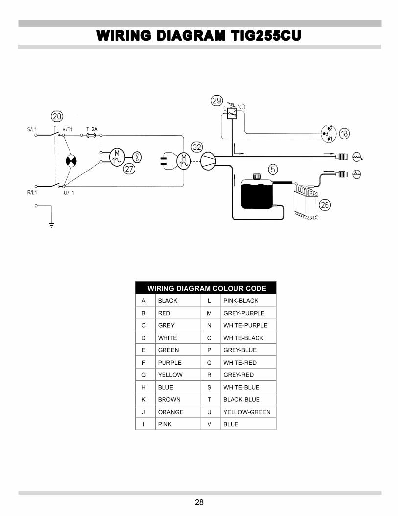
WIRING DIAGRAM TIG255CU
WIRING DIAGRAM COLOUR CODE A BLACK L PINK-BLACK
B RED M GREY-PURPLE
C GREY N WHITE-PURPLE
D WHITE O WHITE-BLACK
E GREEN P GREY-BLUE
F PURPLE Q WHITE-RED
G YELLOW R GREY-RED
H BLUE S WHITE-BLUE
K BROWN T BLACK-BLUE
J ORANGE U YELLOW-GREEN
I PINK V BLUE
29
Snap-on Tools Company Limited Two (2) Year Warranty
Snap-on Tools Company (the “Seller") warrants only to original purchasers who use the Equipment in their business that under normal use, care and service, the Equipment (except as otherwise provided herein) shall be free from defects in material and workmanship for two years from the date of original invoice. Seller does not provide any warranty for accessories used with the Equipment that are not manufactured by Seller. Seller limits torch assembly to a period of 30 days. SELLER'S OBLIGATIONS UNDER THIS WARRANTY ARE LIMITED SOLELY TO THE REPAIR OR, AT SELLER'S OPTION, REPLACEMENT OF EQUIPMENT OR PARTS WHICH TO SELLER'S SATISFACTION ARE DETERMINED TO BE DEFECTIVE AND WHICH ARE NECESSARY, IN SELLER'S JUDGMENT, TO RETURN THIS EQUIPMENT TO GOOD OPERATING CONDITION. NO OTHER WARRANTIES, EXPRESS OR IMPLIED OR STATUTORY, INCLUDING WITHOUT LIMITATION ANY IMPLIED WARRANTY OF MERCHANTABILITY OR FITNESS FOR A PARTICULAR PURPOSE, SHALL APPLY AND ALL SUCH WARRANTIES ARE HEREBY EXPRESSLY DISCLAIMED. SELLER SHALL NOT BE LIABLE FOR ANY INCIDENTAL, SPECIAL OR CONSEQUENTIAL COSTS OR DAMAGES INCURRED BY PURCHASERS OR OTHERS (including, without limitations, lost profits, revenues, and anticipated sales, business opportunities or goodwill, or interruption of business and any other injury or damage). This warranty does not cover (and separate charges for parts, labor and related expenses shall apply to) any damage to, malfunctioning, inoperability or improper operation of the Equipment caused by, resulting from or attributable to (A) abuse, misuse or tampering; (B) alteration, modification or adjustment of the Equipment by other than Seller's authorized representatives; (e) installation, repair or maintenance (other than specified operator maintenance) of the Equipment or related equipment, attachments, peripherals or optional features by other than Seller's authorized representatives; (D) improper or negligent use, application, operation, care, cleaning, storage or handling; (E) fire, water, wind, lightning or other natural causes; (F) adverse environmental conditions, including, without limitation, excessive heat, moisture, corrosive elements, dust or other air contaminants, radio frequency interference, electric power failure, power line voltages beyond those specified for the Equipment. unusual physical, electrical or electromagnetic stress and/or any other condition outside of Seller's environmental specifications; (G) use of the Equipment in combination or connection with other equipment, attachments, supplies or consumables not manufactured or supplied by Seller; or (H) failure to comply with any applicable federal, state or local regulation, requirement or specification governing welders and related supplies or consumables. Repairs or replacements qualifying under this Warranty will be performed on regular business days during Seller's normal working hours within a reasonable time following purchaser's request. All requests for Warranty service must be made during the stated Warranty period. Proof of purchase date is required to make a Warranty request. This Warranty is nontransferable.
Snap-on Tools Company
Kenosha, Wisconsin 53141-1410 Technical Support Line 800-ABC-WELD
Customer Service and Technical Support 800-ABC-WELD
Monday – Friday 7:00 a.m. – 3:00 p.m. EST
Made in Italy Snap-on and Wrench “S” are trademarks of Snap-on Incorporated. ©Snap-on Incorporated 2011. All Rights Reserved. Printed in United States Snap-on, 2801 80th St., Kenosha, WI 53143 www.snapon.com
WARRANTY/SERVICE AND REPAIR