22 TI T A - Sew Machine Equipment | Sewing| Cutting| … · p r ti n instf cti n Warning: ... At...
38
22 TI T A CONSEW U@S@A@-JAPAN
Transcript of 22 TI T A - Sew Machine Equipment | Sewing| Cutting| … · p r ti n instf cti n Warning: ... At...
22
TI
T A
CONSEW U@S@A@-JAPAN
p r ti n instf cti n Warning:
1. All parts designs are subject to revison,and parties to ~greements wouldn't be
moticed.
2. Non-Professional wouldn't adjust and maintain the machine except adjustiong
the stitch.
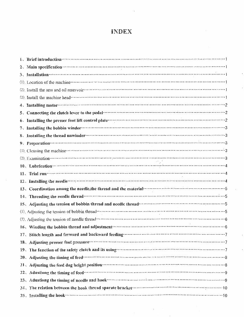
INDEX
1, Brief introduction'" ................. , ............................. , ..... , '" ............ '" .............................. "·1
2, Main specification .. · .. · .. · .. · .. · .. · .. ·· ................. ~ ................................................................. '''1
3, Installation .. · .. · .. · .. · .. ·· .. · .... ·· .... ····· .. · .. ··· .. · .. · .. ·· .. · .... ·· .... · .. · .. · .. · .. · .. · .. · .. ·· .... ·· .... · .. · .. · .. · .. · .. · .. ·1
(1). Location of the Inachine .. · .. · .. · .. · .. · .. ·· .... · .. · .. · .. ·· .... · .. · .. · .. · .. · .. ·· .... · .. · .. · .. · .. · .. · .. · .. ····· .... · .. · .. ·· .... ·1
(2). Install the ann and oil reservoir'" ..... , '" ........ , ....... " ............................. , .............................. "·1
(3). Install the machine head'" ................................................................................................ "·1
4, Installing motor······ .. ···· .. · ............................................................ ··· .. ···· .. ·· .. · .. ··· .. ·· .... ···· .. ·2
5, Connecting the clutch lever to the peda) .. · .. · .. · .. · .. · ............................................... ····· .... · .. · .. · .. ·2
6, Installing the presser foot lift control plate .... : .. · ................................................................... "·2
7, Installing the bobbin winder'" ............................................ ' .............................................. ' .. 3
~L Installing the thread unwinder· .. · .. ···· .... ·· .. · .... · .. · .. ·· .... ·· .... ·· .. · .. ··· .. · .. ·· .... · .. · .. · .. · .. ·· .... ···· .. ···· .. ·3
9, Preparation······ .. · .. ·· .. · .. ··· .. · .. · .. · .. · .. · .. ·· .. · .... ·· .. ··· .. · .. ···· .. · .. · .. · .. ···· .. · .. · .. · .. · .. · .. · .. ··········· .. ·, .... ·3
(1). Cleaning the machine .. ···· .. · .............................................................................. '" ............ "'3
(2). Examination .. · .. · .. · .. · ........................................................... , ........................................... "·3
10, Lubrication .. ·· .... · .. ·· .. ···· .... ···· .. · .. ···· .. · .. ·· .... · .. · .. ·· .. · .. · .... ··, .... ·; .... · .. · .. · .. · .. · .. ·· .. · .... ·· .... ·· .. · .. 4
11, Trial run .. ·· .............................................................................................................. '''4
12, Installing the needle .. ···:· .. · .. · .... ·· .... · .. · .. · .. · .. · .. · .. ·· .... ·· .. · .... · .. ·· .... · .. · .. ·· .... ·· .... · .. · .. · .. ·· .. · .... · .. ·4
13, Coordination among the needle,the thread and the material .. · .... · .............. · .. ·; ................ · .......... 5
14, Threading the needle thread· .... ·· .... · .. · ........................................................................... "'5
15, Adjusting the tension of bobbin thread and needle thread ...... · .. · .... · .. · .................... · .......... · .... · .. 5
(1). Adjusting the tension of bobbin thread· .... · .. · .. ·· .... · .. · .. · .. ·· .... ·· .. · .... · .. ·· .... · .. · .. ·· .... · .. ·· .... · .. · .. ~ .. · "'5
(2). Adjusting the tension of needle thread'" .............................................................................. "'6
16, Winding the bobbin thread and adjustment .. · .. · .. · .. · .. ·· .... ·· .... ·· .. · .... · .. · ........ ·· .... · .. · .. · .. ·· .... ·· .. · .. 6
17, Stitch length and forward and backward feeding'" .... , ....................... , ................ '" ............... 7
18, Adjusting presser foot pressure· .. · .... · .. · .. · .. · .. · .. · .. · .. · .. ·· .... ·· .... · ............................................. 7
19, The function ofthe safety clutch and its using'" ..................................................................... 7
20, Adjusting the timing offeed· .. · .. · .... · .. · .. ·· .... ·· .... · .. ··, .... ·· .. ··· .. · .. · .. · .. · .. · .. · .. · .. · .. · .. ·· .... · .. ·· .... · .. ·8
21, Adjusting the feed dog height position .. · .. · .. · .. ·· .... · .. · .. ·· .... · .. · ............................................. "'8
22, Adustiong the timing offeed .. ·· .. · .. ··· .. · .. · .. ·· .... ·· .... ·· .. · .. · .. ··· .. · .. ···· .. · .. · .. · .. · .. · .. ·· .. , .. ·· .... ···· .. · .. ·9
23, Adustiong the timing of needle and hook ............................................................................ "'9
24, The relation between the hook thread sparate bracket ........ · ...... ; ................................ ~·""·""·1 0
25, Installing the hook .. · .. ·· .... · .. · .. ·· .. · .... · .. · .. · .. · .. ·· .... · .. · .. · .. · .. · .. ·· ........................................... ·1 0
1. Brief Introduction It's designed with sliding lever thread take-up, vertical
rotating hook to produce double lockstitch; gear band
for driving arm shaft and hook shaft, lever type stitch
regulator, compound feed by presser foot, feed dog and
needle. And the clutch safe device is installed to prevent
the damage. It is easy for sewing more lays leather with
high presser foot lift, large stitch length and cylinder
bed.
It's widely used for sewing heavy-duty luggage suitcase,
seat cushion, especially for cylinder and curve articles.
It's a essential equipment for edge seaming.
3. Installation (I) Location of the machine
The machine must be located on rigid and flat floor for
ensuring its smooth operation and reducing its vibration.
Furthermore, a rubber mat should be inserted between
the machine stand and the floor for further reducing the
running noise.
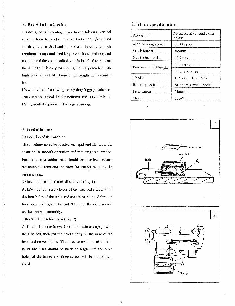
(2) Install the arm bed and oil reservoir(Fig. 1)
At first, the four screw holes of the arm bed should align
the four holes of the table and should be plunged through
four bolts and tighten the nut. Then put the oil reservoir
on the arm bed smoothly.
(3)Install the machine head(Fig. 2)
At frist, half of the hings should be made to engage with
the ann bed, then put the head lightly on the base of the
head and move slightly. The three screw holes of the hin
gs of the head should be made to align with the three
holes of the hinge and three screw will be tighten and
fixed.
-1-
2. Main specification
Application Medium, heavy and extra heavy
Max. Sewing speed 2200 s.p.m.
Stitch length O-Smm
Needle bar stroke 33.2mm
Presser foot lift height 8.Smm by hand
14mm by knee
Needle DPXl7 18#~23#
Rotating hook Standard vertical hook
Lubrication Manual
Motor 370W
~Oil reservoir
Arm bed
Hinge
2

G
F
E--D---':-l:-llJ
cB---Y(/.
A~~=:;J
B
4. Installing the motor (Fig. 3) Align machine balance wheel belt groove A with motor
pulley belt groove B by moving motor C leftward or
rightward. Be sure the belt is not touched with the table.
5. Connecting the dutch lever to the pedal (Fig. 4)
1) The optimun tilt angle of pedal A against floor is ap
propriate 15 degree.
2) Adjust the E clutch of the motor so that clutch lever C
and draw bar B TIm in one line.
3) The machine balance wheel should rotate counter
clockwise for mormal sewing when obsered from oppo
site side of the balance wheel. The motor rotates in the
same direction. The rotation can be reversed by reversing
the plug of the motor.
4) Adjust the tension of V-belt F by moving vertically.
The proper tension of V-belt is a slack of 1O-12mm when
the belt is depressed by forefinger.
6. Installing the presser foot lift control plate(Fig. 5)
At first, the hook A should be connected to the chain B
and presser foot lift lever C, then put the pedal complete
D on the stand. And move the control plate E leftward
or rightward until the chain becomes on one line. Tigh
ten the bolts and nuts, finally, connect the finger to the
control plate.
-2-

7. Installing the bobbin wimller(Figo 6) Align pulley B of the bobbin winder with the outside of
the belt C. And there should be a proper cleara,nce be
tween them, so that pulley B can be contacted with the
belt when latch thumb lever A is depressed, thereby the
belt can drive pulley B while the machine running. The
bobbin winder should be parallel with belt slit E of the
table, then fasten two wood screws D.
80 Installing the thread unwinder (Fig. 7) The thread unwinder should be located on the right
backside of the table. Threading should be smooth when
sewing. And the spool rest may not be obstructed when
the machine headis tumed backward, then tighten wood
screw C.
9. Preparation (1) Cleaning the machine
Before the head is packed, all the patiS of the machine
are coated with preventive grease, meanwhile the hard
ened grease and converged dust on the machine surface
during long storage and shipment must be removed by
clean cloth with gasoline.
(2) Examination
The parts of the machine may by loose and deformed
after long distance transportation with jolt though every
machine is confirmed by strict inspection and test before
delivelY A thorough examination must be performed
after cleaning the machine. Tum the balance wheel to
check if there are running obstruction, patis collision,
uneven resistance of abnormal noise. If any of these
exist, adjustment must be made accordingly before
rmming.
A
!<..----o
-3-
9
Long goove leftward a
x x b c
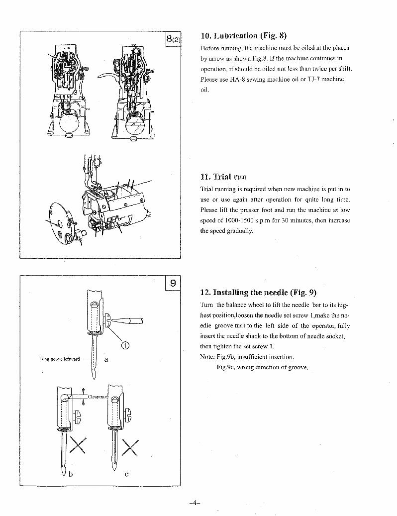
10. Lubrication (Fig. 8) Before mnning, the machine must be oiled at the places
by arrow as shown Fig.S. If the machine continues in
operation, if should be oiled not less than twice per shift.
Please use HA-S sewing machine oil or TJ-7 machine
oil.
11. Trial run Trialmnning is required when new machine is put in to
use or use again after operation for quite long time.
Please lift the presser foot and mn the machine at low
speed of 1000-1500 s.p.m for 30 minutes, then increase
the speed gradually.
12. Installing the needle (Fig. 9) Tum the balance wheel to lift the needle bar to its hig
hest position,loosen the needle set screw 1 ,make the ne
edle groove tum to the left side of the operator, fully
insert the needle shank to the bottom of needle socket,
then tighten the set screw 1.
Note: Fig.9b, insufficient insertion.
Fig.9c, wrong direction of groove.
-4-
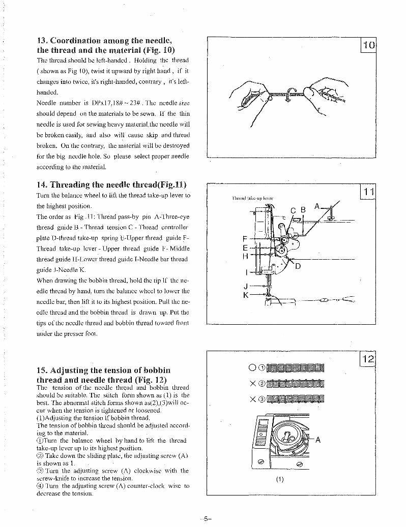
13. Coordination among the needle, the thread and the material (Fig. 10) The thread should be left-handed. Holding the thread
( shown as Fig 10), twist it upward by right hand, if it
changes into twice, it's right-handed, contrary, it's left
handed.
Needle number is DPxI7, 18# ~ 23# . The needle size
should depend on the materials to be sewn. If the thin
needle is used for sewing heavy material,the needle will
be broken easily, and also will cause skip and thread
broken. On the contrary, the material will be destroyed
for the big needle hole. So please select proper needle
according to the material.
14. Threading the needle thread(Fig.U) Tum the balance wheel to lift the thread take-up lever to
the highest position.
The order as Fig .11: Thread pass-by pin A-Three-eye
thread guide B - Thread tension C - Thread controller
plate D-thread take-up spring E-Upper thread guide F
Thread take-up lever - Upper thread guide F - Middle
thread guide H-Lower thread guide I-Needle bar thread
guide }-Needle K.
When drawing the bobbin thread, hold the tip If the ne
edle thread by hand, tum the balance wheel to lower the
needle bar, then lift it to its highest position. Pull the ne
edle thread and the bobbin thread is drawn up. Put the
tips of the needle thread and bobbin thread toward front
under the presser foot.
15. Adjusting the tension of bobbin thread and needle thread (Fig. 12) The tension of the needle thread and bobbin thread should be suitable. The stitch form shown as (1) is the best. The abnormal stitch forms shown as(2),(3)will occur when the tension is tightened or loosened. (I)Adjusting the tension If bobbin thread. The tension of bobbin thread should be adjusted according to the material. CDTum the balance wheel by hand to lift the thread take-up lever up to its highest position. @ Take down the sliding plate, the adjusting screw (A) is shown as 1. ® Turn the adjusting screw (A) clockwise with the screw-knife to increase the tension. @) Tum the adjusting screw (A) counter-clock wise to decrease the tension.
-5-
Thread take-up lever
I .......jI€tE:'::3
J--Id;;. K--¢>}!l1L
~"T--""'_~
00)_
x®_ x®_
A
(1 )
A
Standard clearance
(3)
(4)
B A
c
® D
""'L'-+--- E
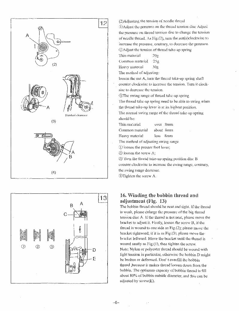
(2)Adjusting the tension of needle thread
CDAdjust the pressure on the thread tension disc Adjust
the pressure on thread tension disc to change the tension
of needle thread. As Fig.(2), turn the nut(a)clockwise to
increase the pressure, contrary, to decrease the pressure.
@Adjust the tension of thread take-up spring
Thin material 20g
Common material 25g
Heavy material 30g
The method of adjusting:
loosen the nut A, tlml the thread take-up spring shaft
counter clockwise to increase the tension. Turn it clock
sise to decrease the tension.
@The swing range of thread take-up spring
The thread take-up spring need to be able to swing when
the thread take-up lever is at its highest position.
The normal swing range of the thread take-up spring
should be:
Thin material over 8mm
Common material about 8mm
I-Ieavy material less 8mm
The method of adjusting swing range
CD loosen the presser foot lever;
@ loosen the screw A;
@ Turn the thread take-up spring position disc B
counter clockwise to increase the swing range, contrary,
the swing range decrease.
@Tighten the screw A.
-6-
16. Winding the bobbin thread and adjustment (Fig. 13) The bobbin thread should be neat and tight. If the thread
is weak, please enlarge the pressure of the big thread tension disc A. If the tIn'ead is not neat, please move the
bracket to adjust it. Firstly, lossen the screw B, if the thread is wound to one side as Fig.(2); please move the
bracket rightward; if it is as Fig.(3), please move the
bracket leftward. Move the bracket until the thread is wound neatly as Fig.(l), then tighten the screw.
Note: Nylon or polyester thread should be wound with light tension in particular, otherwise the bobbin D might be broken or deformed. Don't overfill the bobbin
thread ,because it makes thread loosen down from the bobbin. The ?ptimum capacity of bobbin thread is fill about 80% of bobbin outside diameter, and this can be adjusted by screw(E).

17. Stitch length and forward and backward feeding (Fig. 14)
Turn the stitch length regulating nut to adjust t~e stitch
length. When tbe graduation on the stitch Length
regulating position block is aligned with the figure on
the stitch length graduated plate, the figure is the stitch
length.Press the reverse feed lever, the feeding is reverse.
Release the lever, the machine recovers normal feeding
agam.
18. Adjusting presser foot pressure (Fig. 15)
Adjust the presser foot pressure according to the ma
terial. Please increase the pressure, when you sew heavy
material. Turn the regulating screw clockwise to increase
the pressure, contrary, decrease the pressure.
19. The function of the safety dutch and its using (Fig. 16)
The function of the safety clutch is preventing the hook
and synchronous belt from destroys when the needle or
thread is drawn into the hook for abnormal load during
the operation.
When the eccentric pin arrow is aligned with the lower
shaft center, the load on the safety clutch is small, in
crease the load when the arrow turns outside. Reset the
safety clutch, the method is : Press the button B by left
hand, and turn the balance wheel clockwise by right
hand. When the stop plate stops the balance wheel, ple
ase turn the balance wheel to make the safety clutch re
turn to the correct position, then release the button. And
the synchronous belt should be installed again. At first,
turn the balance wheel counter-clockwise when the
thread take-up lever is on its highest position, and the
red arrow in aligned with the arrow on the position plate,
Loosen
Lower shaft
-7-
/)
Clock wise
(, II
Arrow
A /
Reverse feed lever
Couutor-clockwise
Eccentric
Red arrow
Position arrow
00
1IIj),,*,,*,!iz,~O.8mm
1II~1.0mm
17l~1.2mm
i1i~1.5mm
-8-
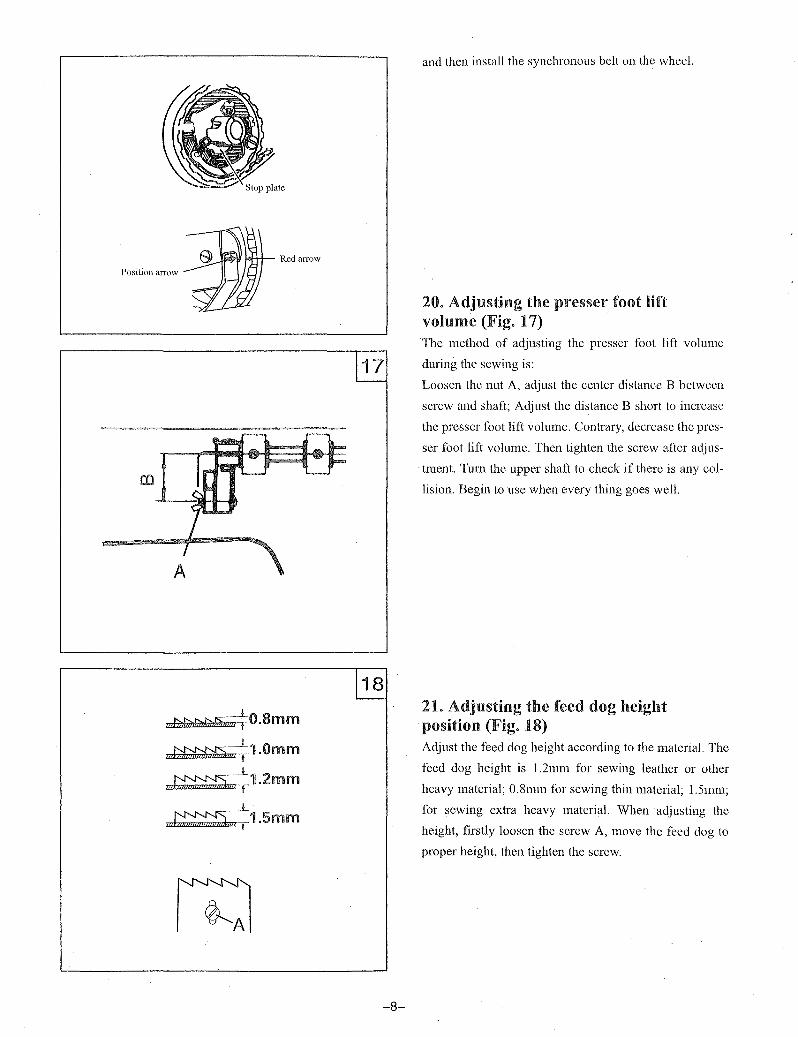
and then install the synchronous belt on the wheel.
20. Adjusting the presser foot lift volume (Fig. 17) The method of adjusting the presser foot lift volume
during the sewing is:
Loosen the nut A, adjust the center distance B between
screw and shaft; Adjust the distance B short to increase
the presser foot lift volume. Contrary, decrease the pres
ser foot lift volume. Then tighten the screw after adjus
tment. Tum the upper shaft to check if there is any col
lision. Begin to use when every thing goes well.
21. Adjusting the feed dog height position (Fig. 18) Adjust the feed dog height according to the material. The
feed dog height is 1.2mm for sewing leather or other
heavy material; O.8mm for sewing thin material; 1.5mm;
for sewing extra heavy material. When adjusting the
height, firstly loosen the screw A, move the feed dog to
proper height, then tighten the screw.
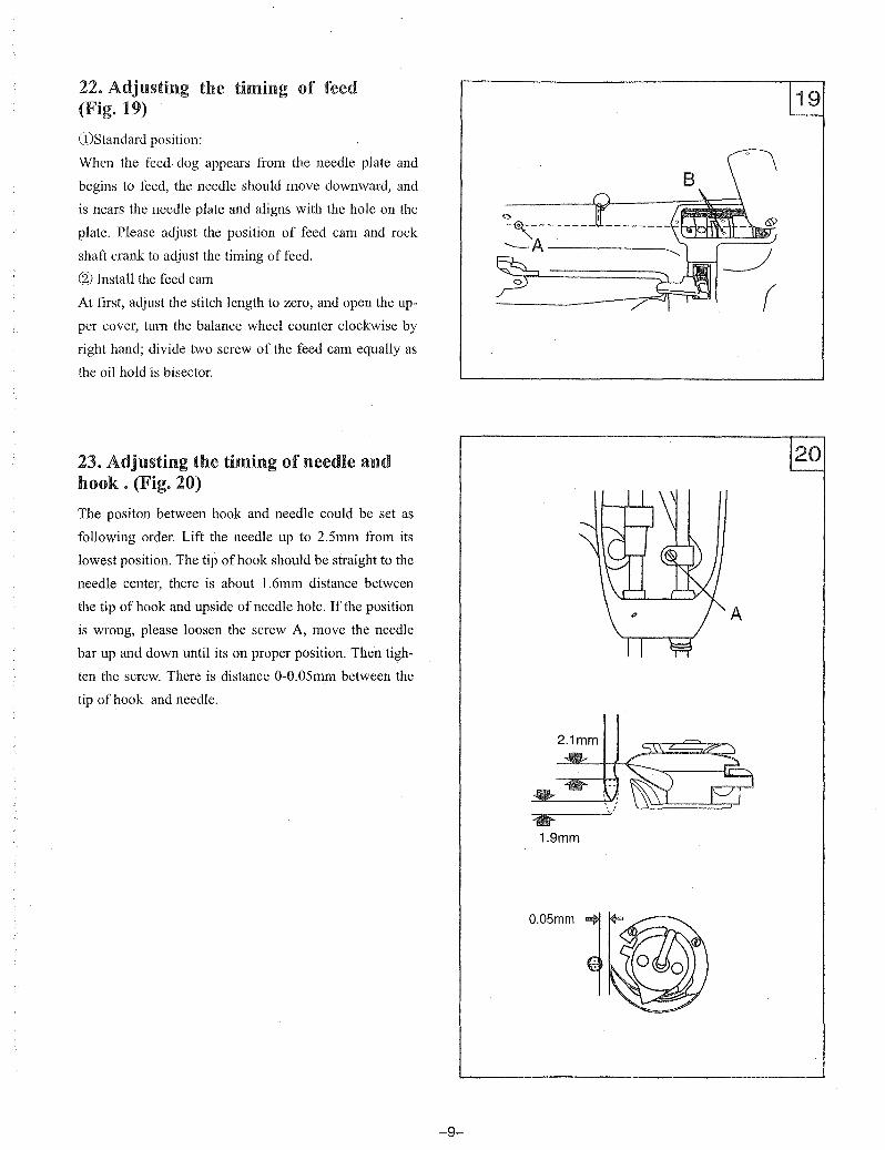
22. Adjusting the timing of feed (Fig. 19)
CDStandard position:
When the feed· dog appears from the needle plate and
begins to feed, the needle should move downward, and
is nears the needle plate and aligns with the hole on the
plate. Please adjust the position of feed cam and rock
shaft crank to adjust the timing of feed.
® Install the feed cam
At first, adjust the stitch length to zero, and open the up
per cover, tum the balance wheel counter clockwise by
right hand; divide two screw of the feed cam equally as
the oil hold is bisector.
23. Adjusting the timing of needle and hook. (Fig. 20)
The positon between hook and needle could be set as
following order. Lift the needle up to 2.5mm from its
lowest position. The tip of hook should be straight to the
needle center, there is about 1.6mm distance between
the tip of hook and upside of needle hole. If the position
is wrong, please loosen the screw A, move the needle
bar up and down until its on proper position. Then tigh
ten the screw. There is distance O-O.OSmm between the
tip of hook and needle.
-9-
2.1mm
• 1.9mm
O.05mm 1
A
1111101111
~~~:----F
C
A
21
-10-
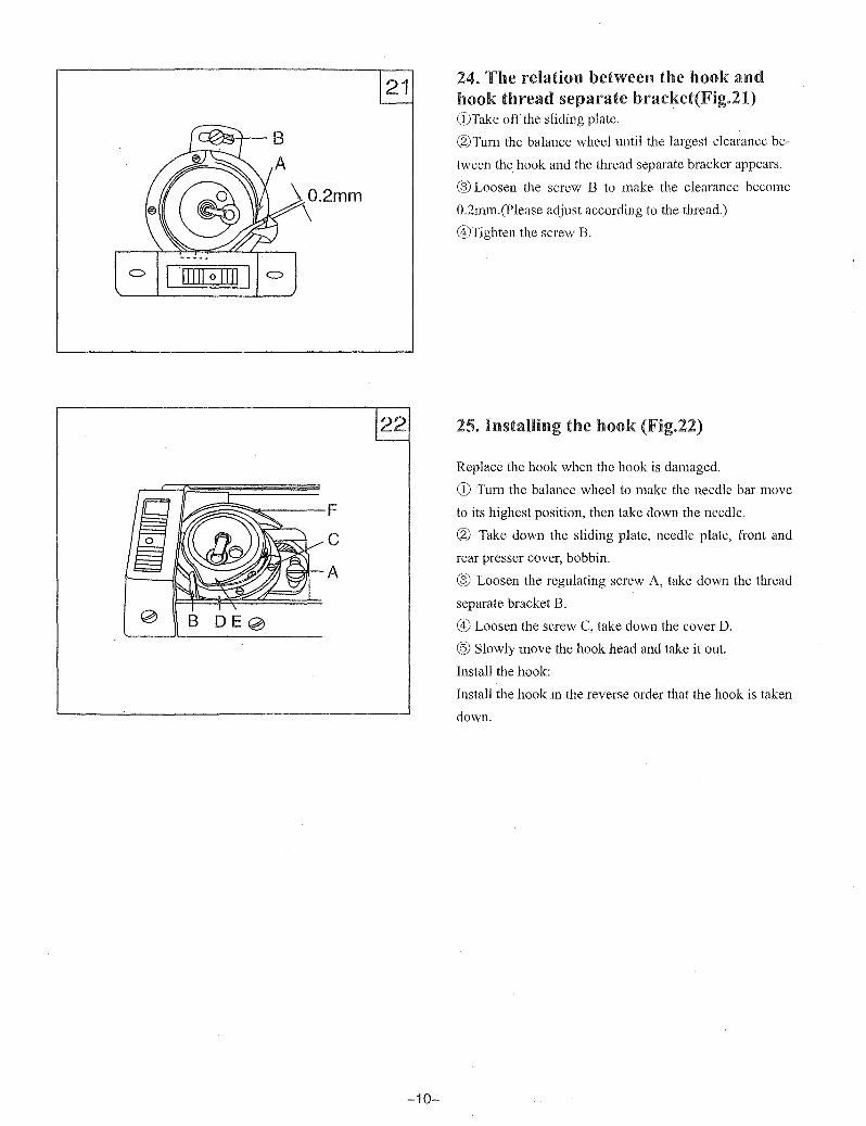
24. The relation between the hook and hook thread separate bracket(Fig.21) CDTake off the sliding plate.
®Turn the balance wheel until the largest clearance be
tween the hook and the thread separate bracker appears.
® Loosen the screw B to make the clearance become
O.2mm.(Please adjust according to the thread.)
®Tighten the screw B.
25. Installing the hook (Fig.22)
Replace the hook when the hook is damaged.
CD Turn the balance wheel to make the needle bar move
to its highest position, then take down the needle.
® Take down the sliding plate, needle plate, front and
rear presser cover, bobbin.
® Loosen the regulating screw A, take down the thread
separate bracket B.
® Loosen the screw C, take down the cover D.
@ Slowly move the hook head and take it out.
Install the hook:
Install the hook in the reverse order that the hook is taken
down.

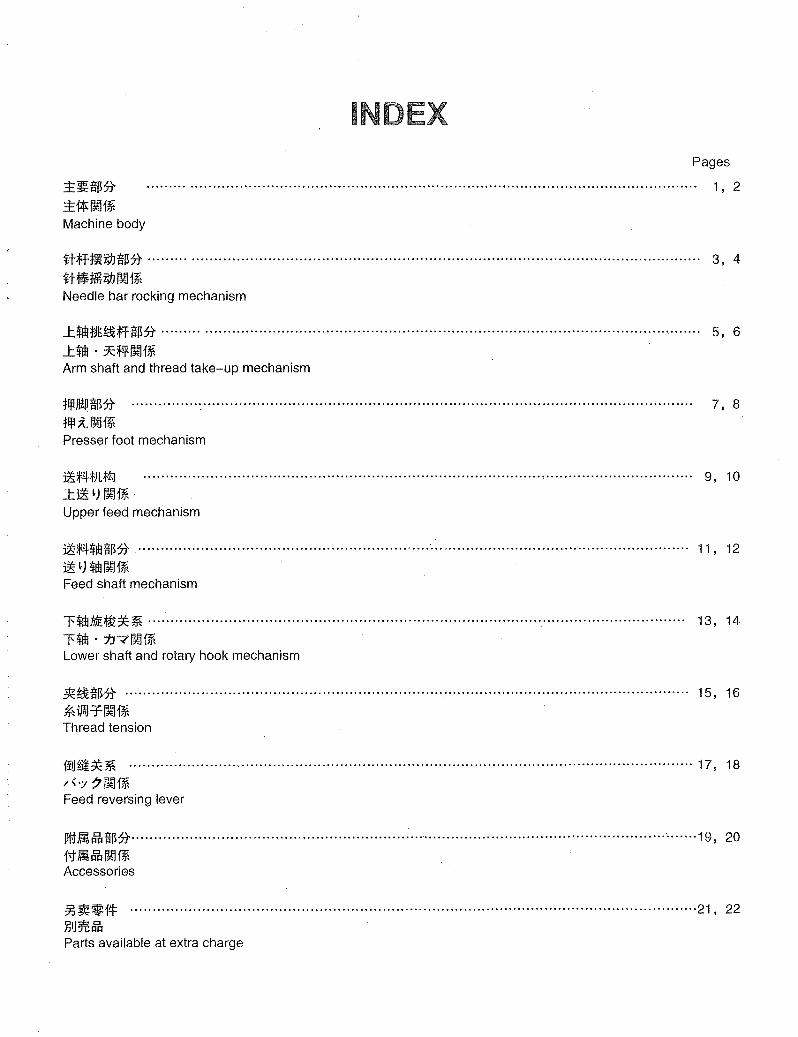
INDEX Pages
::E~:g~it
::E1*~f* Machine body
........................... "................................................................................................ 1, 2
~tff~iW:g~it ......... .................................................................................................................. 3, 4
H~~iW~f* Needle bar rocking mechanism
..t~tI~~ff$it ......... ............................................................................................................... 5, 6
..t~'7CfiI!~f* Arm shaft and thread take-up mechanism
:tIllJWJ:g~it ............... : ....................... ,................... ..................... .............................................. 7, 8
flll~~f~ Presser foot mechanism
1!;f4fJlfZJ ........................................................................................................................... 9, 10
.:t.1! ~) ~f* Upper feed mechanism
1!;f4~dl:g~it ................................................................. ~ ......................................................... 11, 12
1!~)~~f* Feed shaft mechanism
l'~ME~** ........................................................................................................................ 13, 14
1'~.1J-:('~f* Lower shaft and rotary hook mechanism
*~$it .............................................................................................................................. 15, 16
*iPaJT~f* Thread tension
·~tl~*~ ............................................................................................................. ·················17, 18
/{.;t 7~f~
Feed reversing lever
I!ftJl,~$it················································ ...................................................... ·························19, 20 f;tJl,~~~ Accessories
~ ~*f* ............................................................................................................................. '21, 22
l.lIJ~~ Parts available at extra charge

25
~ '.
4
1
17
e I
24
1
~16
l~ 15

*JL1*.:E.~$* / .:E.1*~1* / Machine body
No. ~f*~1i~ !l&; ~1*~~ c::J ~ PARTS NAME t:m
PARTS No. QTY
1 10698 1 iIiH.& iIiH.& FACE PLATE 2 10699A 1 1m f'& [?!] JE: 911 t4: 1m f.<tl t; THUMB SCREW 9/64"X40L=6.5 3 10700 1 1mflH~ iWf.&t::: :-.- PIN 4 10701-A 1 iwti ;wt4:(:k) PLUG 5 10702 1 ..t.t& ..t.t& ARM CAP 6 10703 1 ..t.t&m~ ..t. f'& '7 'Y y "\7- WASHER 7 10704 1 !I!I~ ..t.f.&~tl t; SCREW 3/16X28 L=6.5 8 10551 1 t:J~~;ffMiwf'& 7C~iw~ OIL GUARD 9 10650A 1 M iw f'& [?!] JE:911 ~ 7C~;W~lttl t; SCREW 9/64"X40L=6.0 10 13009 1 ~~'il~~ilft y I) :-'-9"-tJ/\- BED END COVER 11 13026 1 g:t nH'&ft ~*A. ~ L f.&~r*J(ft) GUIDE PLATE (REAR» 12 13025 1 g:tfit&::t:l~*A. ~ L *.&~r*J(::t:l) GUIDE PLATE(FRONT) 13 13027A 4 911~ lttlt; SCREW 9/64"X40L=6,O 14 13024 1 g:tfif,& ~Lf'& BED SLIDE PLATE 15 13004 1 ~~ ~:m= BED HINGE 16 37100A 6 911~ lttlt; SCREW M6X1L=10.0 17 13383 1 ~~ ""-..:A MACHING BASE 18 13006 1 ilJiif!j m BED CLAMP 19 19403 1 ijJHf!j9l1~ tJ.:flttlt; HINGE SCREW 1/4X28 L=5.4 20 13008 1 m~ '7'yy"\"'- WASHER 21 13388-A 1 ~M9II~ ~*)v r M6X1 SCREW M6X1 L=20.0 22 13096A 4 ifL~91It4: .IlllfJ\tl t; 5/16X18L= 75 SCREW M8 L=75 23 13096-W 4 m~ '7 'Yy"\"'- WASHER 24 13096-NA 4 911£;1: 7'Y r NUTM8 25 30046 1 [?!] JE::tI!! ~ Jfj9l1 H: 7-..:A*,,'J(lttl t; EARTH WIRE SCREW M4XO.7L=4.0
2
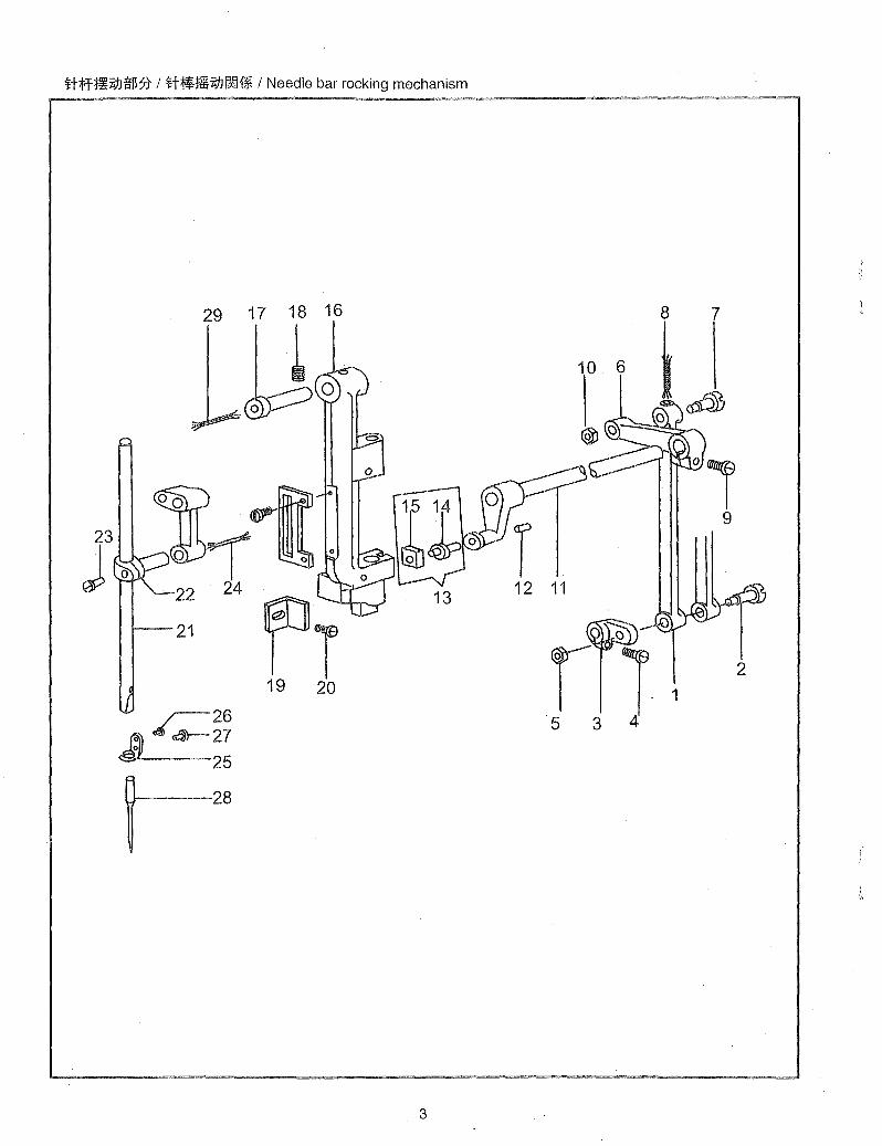
Hiff~ZdJtm)t / H~mZdJ~1¥ / Needle bar rocking mechanism
29 17 18 16
--""",-
. 22
21
~26 A aa-27 25
t-28
l ~O
3
7
10 6
12 11
o
r 11 5 3 4
2
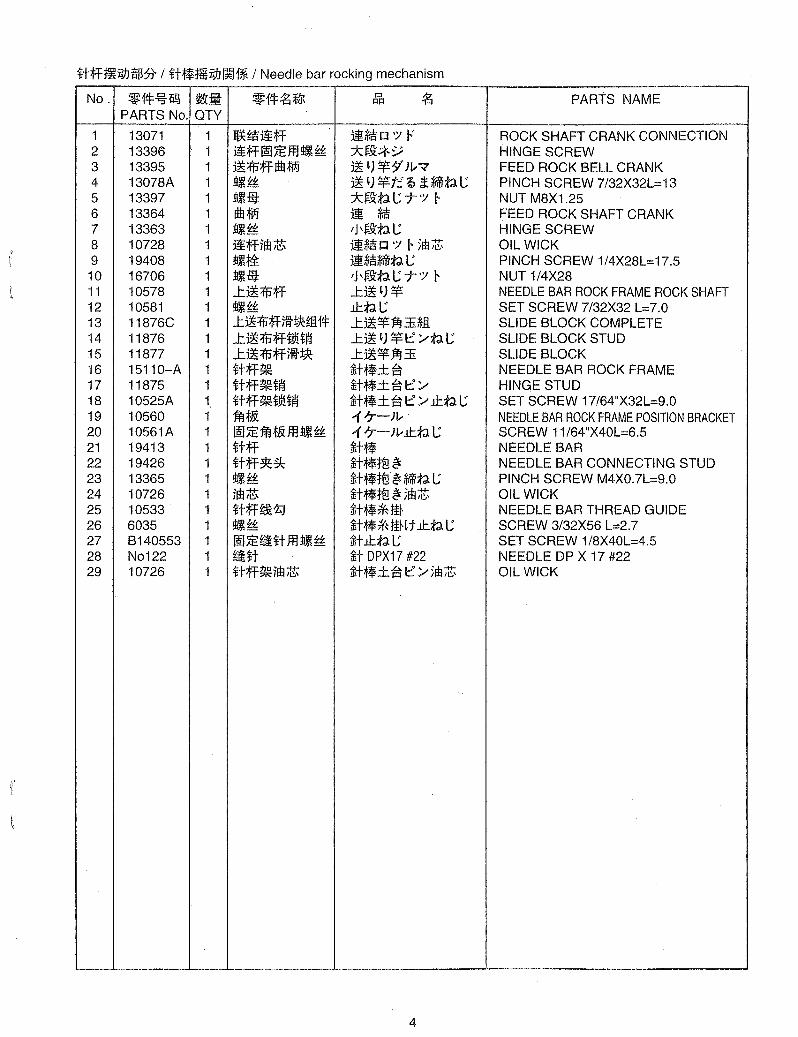
n;ff~Mfm:5t I n~mMM1* I Needle bar rocking mechanism
No. ~1*~1i~ !J&fi ~1*~ff.jt CJ ~ PARTS NAME J:!J:!
PARTS No. QTY
1 13071 1 1f*~~;ff ijmi!i IJ ':J F' ROCK SHAFT CRANK CONNECTION 2 13396 1 ~;ff~;Effl!I!J~ *~~*y HINGE SCREW 3 13395 1 ~:(jJ;ffRflfpj ~ ')¥7'Jv?' FEED ROCK BELL CRANK 4 13078A 1 !I11~ ~ ') ¥t:.' Q £**tJ. C PINCH SCREW 7/32X32L=13 5 13397 1 !111m: *~~tJ. C 7" ':J I- NUT M8X1.25 6 13364 1 Rflfpj ij ~ FEED ROCK SHAFT CRANK 7 13363 1 !I11~ IJ\~~tJ.C HINGE SCREW 8 10728 1 ~;ffilEi$ ij~ IJ ':J I- 51E;& OIL WICK 9 19408 1 !l!Jfi ijmi!i**tJ. L; PINCH SCREW 1/4X28L=17.5 10 16706 1 !111m: I J \~~tJ. L; 7" ':J I- NUT 1/4X28 11 10578 1 ..t~:(jJ;ff ..t~')¥ NEEDLE BAR ROCK FRAME ROCK SHAFT 12 10581 1 !I11~ .tl:tJ.L; SET SCREW 7/32X32 L=7.0 13 11876C 1 .L~:{fjf.Fm±Ji!:ffi 14: J:.~ ¥ 1£l ::.EJEI. SLIDE BLOCK COMPLETE 14 11876 1 ..t ~ :(jJ;ff~lI! tf'j J:.~ ') ¥i::: /tJ. L; SLIDE BLOCK STUD 15 11877 1 ..t~:(jJ;ffm~ J:.~¥1£l3i SLIDE BLOCK 16 15110-A 1 n;ff~ H:f*±i3 NEEDLE BAR ROCK FRAME 17 11875 1 n;ff~tf'j iliN*±i3i:::/ HINGE STUD 18 10525A 1 ~t;ff~~lI!tf'j Ht*± i3i::: / .tl:tJ. L; SET SCREW 17/64"X32L=9.0 19 10560 1 1fiJt& -17-Jv NEEDLE BAR ROCK FRAME POSITION BRACKET 20 10561A 1 ~;E1fiJt&ffl!I!J~ -17-) v.tl:tJ. L; SCREW 11 /64"X40L=6.5 21 19413 1 n;ff iliN* NEEDLE BAR 22 19426 1 n;ff~~ Ht*;j:§~ NEEDLE BAR CONNECTING STUD 23 13365 1 !I!J~ ffiN*;j:§~ ~tJ. L; PINCH SCREW M4XO.7L=9.0 24 10726 1 im~ ffiN*;j:§ ~ 51E;& OIL WICK 25 10533 1 It;ff~~ ffitt**Ji~ NEEDLE BAR THREAD GUIDE 26 6035 1 !I11~ ffiN** JiH t .tl:tJ. L; SCREW 3/32X56 L=2.7 27 B140553 1 ~ ;E~jHt ffl!l11 ~ ilit.tl:tJ. C SET SCREW 1/8X40L=4.5 28 No122 1 tin H DPX17 #22 NEEDLE DP X 17 #22 29 10726 1 n;ff~ilEi$ ffitt*± i3i::: /5Eb;& OIL WICK
4

L~art:jt~;jf~~:5f I ... Urn . :7i2;pjII~H* I Arm shaft and thread take-up mechanism
9 10 11
6
~
fr 14 13 12
35 33- 36
i 16 17
5
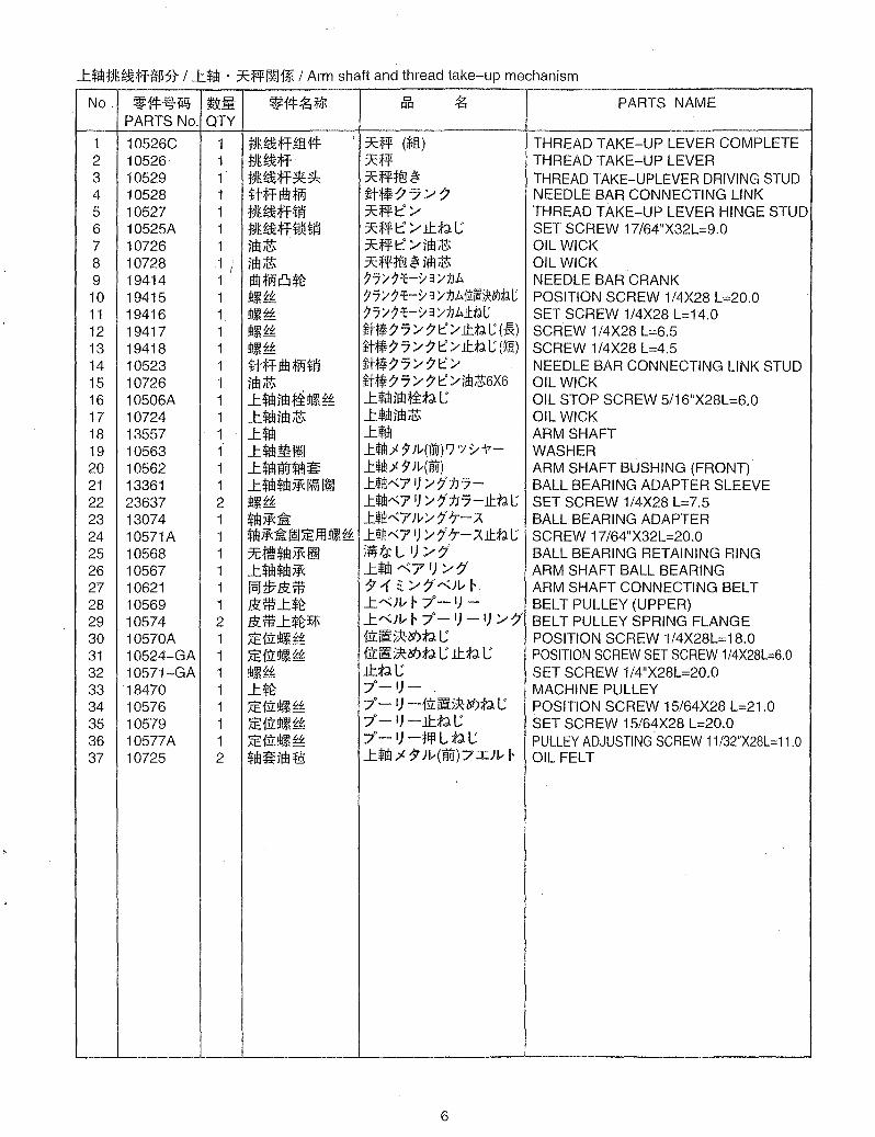
L$lIltJt~ff~~~ I L$IIl . :J;:;f1Ii.~1* I Arm shaft and thread take-up mechanism
No. ~1tJ:~ii~ ~.m ~1tJ:~ffR Cl ~ PARTS NAME r:lr:l
PARTS No. QTY
1 10526C 1 tJt ~ ff ffi. ftJ: :J;:;f1Ii. (~Jl) THREAD TAKE-UP LEVER COMPLETE 2 10526· 1 tJt~ff :J;:;f1Ii. THREAD TAKE-UP LEVER 3 10529 1 tJt~ff~~ :J;:;f1Ii.t§~ THREAD TAKE-UPLEVER DRIVING STUD 4 10528 1 Hffrtll:Wi M:f$77/' 7 NEEDLE BAR CONNECTING LINK 5 10527 1 tJt~ffti1J :J;:;f1Ii.t/, THREAD TAKE-UP LEVER HINGE STUD 6 10525A 1 tJt~fff)Jiti1J :J;:;f1Ii.t/,lt.;fd.I; SET SCREW 17/64"X32L=9.0 7 10726 1 jm~ :J;:fft /'im~ OIL WICK 8 10728 1 I jm~ :J;:;f1Ii.t§ ~ im ~ OIL WICK 9 19414 1 rtIl:Wi~*t j7/j1::-YS/1J~ NEEDLE BAR CRANK 10 19415 1 !l!J~ j7/j1::-ys/1J~~I*~~l POSITION SCREW 1/4X28 L=20.0 11 19416 1 !l!J~ j7/j1::-ys/1J~.tl:~l SET SCREW 1/4X28 L=14.0 12 19417 1 !l!J~ ilit~77/7t'/ J.t~I.;(:&) SCREW 1/4X28 L=6.5 13 19418 1 !l!J~ ilit~77/7t:/ J.t~1.; (~R) SCREW 1/4X28 L=4.5 14 10523 1 Hffrtll:Witi1i ilit~77/7t'/ NEEDLE BAR CONNECTING LINK STUD 15 10726 1 jfH~ ilit~77/7t'/illl~6X6 OIL WICK 16 10506A 1 L$IIlim Mi:!l!J ~ L,1Il im ;J1:;fd. I; OIL STOP SCREW 5/16"X28L=6.0 17 10724 1 L$IIlim~ L,lIljm~ OIL WICK 18 13557 1 L$IIl L,1Il ARM SHAFT 19 10563 1 L$IIlm~ .Hm;< IJ JL{iwY7 "J :/ 1'- WASHER 20 10562 1 L$IIlmr$lll~ L*Hl;< IJ )L{i) ARM SHAFT BUSHING (FRONT) 21 13361 1 L$IIl$IIli1i:~ ~ . HiIlA(7I) /!ftJ7- BALL BEARING ADAPTER SLEEVE 22 23637 2 !l!J~ L*HlA(7 1) /!ftJ7-J.t~1.; SET SCREW 1/4X28 L=7.5 23 13074 1 $IIli1i:~ L*HlA(7)J.; /7" 'r-A BALL BEARING ADAPTER 24 10571A 1 $Iil jft ~ 1E;E.Ill !lt~ ~ L*HlA(7 1) /7'·'r-AJ.t~1.; SCREW 17/64"X32L=20.0 25 10568 1 :7C li!UIll i1i: ~ 5.f,t L I) /' 7' BALL BEARING RETAINING RING 26 10567 1 L$IIl*IIli1i: L,1Il ".71) /'7" ARM SHAFT BALL BEARING 27 10621 1 fBltl7Slrt; 7 ~ ~ /'7"".;J,.. r ARM SHAFT CONNECTING BELT 28 10569 1 Slrt;L*t L".)J,.. r 7°- 1)- BELT PULLEY (UPPER) 29 10574 2 J1l * L*t!il\ L".)J,.. r 7°-1) -I) /'7" BELT PULLEY SPRING FLANGE 30 10570A 1 iE11i:!l!JH: f1i:fif5~lIt.>;fd. I; POSITION SCREW 1/4X28L=18.0 31 10524-GA 1 iEf1i:!l!J~ f1i: fif 5~ lIt.>;fd. I; It.;fd. I; POSITION SCREW SET SCREW 1/4X28L=6,O 32 10571-GA 1 !l!J~{: It.;fd.I; SET SCREW 1/4"X28L=20.0 33 18470 1 L*t 7°-1)- MACHINE PULLEY 34 10576 1 iE f1i:!l!J ~{: 7° - I) -f1i:fif5~lIt.>;fd. I; POSITION SCREW 15/64X28 L=21.0 35 10579 1 iE f1i:!l!J ~{: 7° - I) -It.;fd. I; SET SCREW 15/64X28 L=20.0 36 10577A 1 iEf1i:!l!J~ 7° - I) -llfl L ;fd. I; PULLEY ADJUSTING SCREW 11/32"X28L=11.0 37 10725 2 $1Il~jm :£§: L,1Il ~ 7 )J,..{mi) 7 IlJ,.. r OIL FELT
6
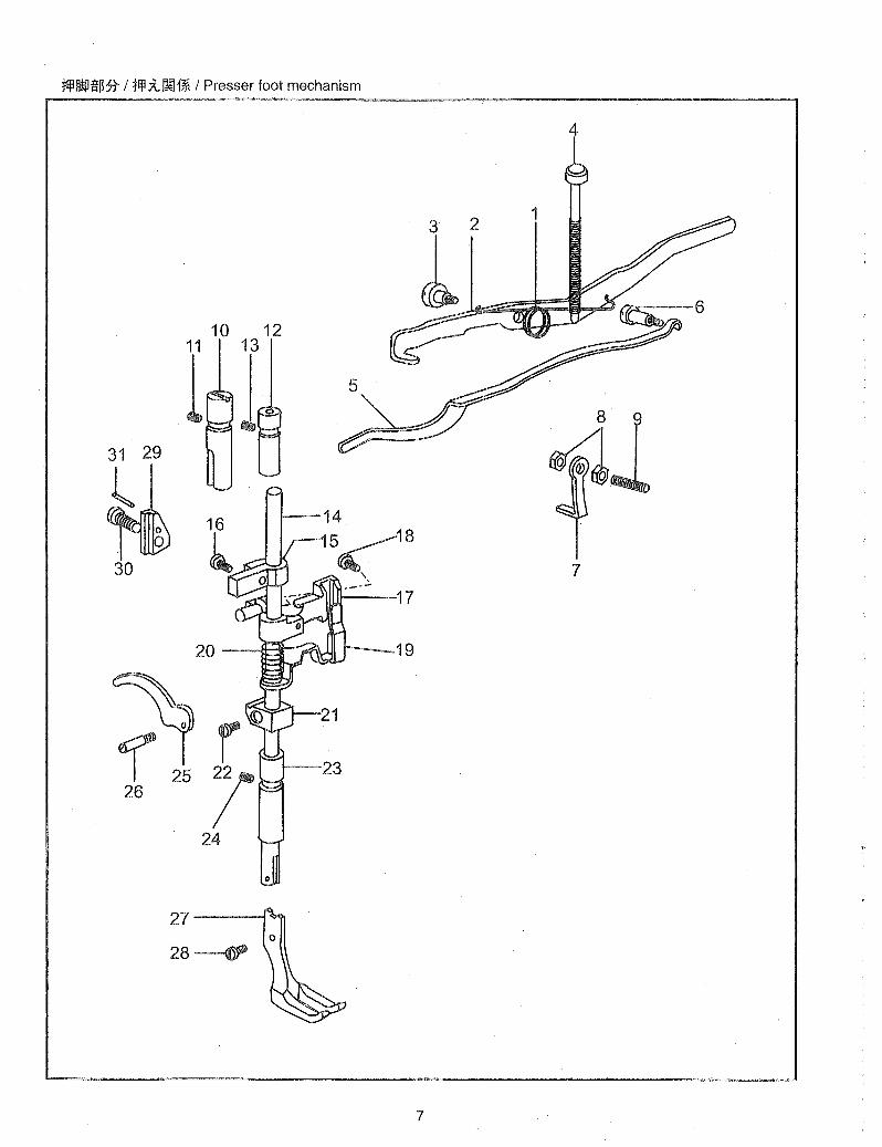
tIflMP~~* / flfl;t~1* / Presser foot mechanism
4
25 26
7
tlfl/l!llffB5t I tlfl~~1* I Presser foot mechanism
No. ~f*~1i~ ~:11 ~f*~~ I:J ~ PARTS NAME QQ
PARTS No. QTY
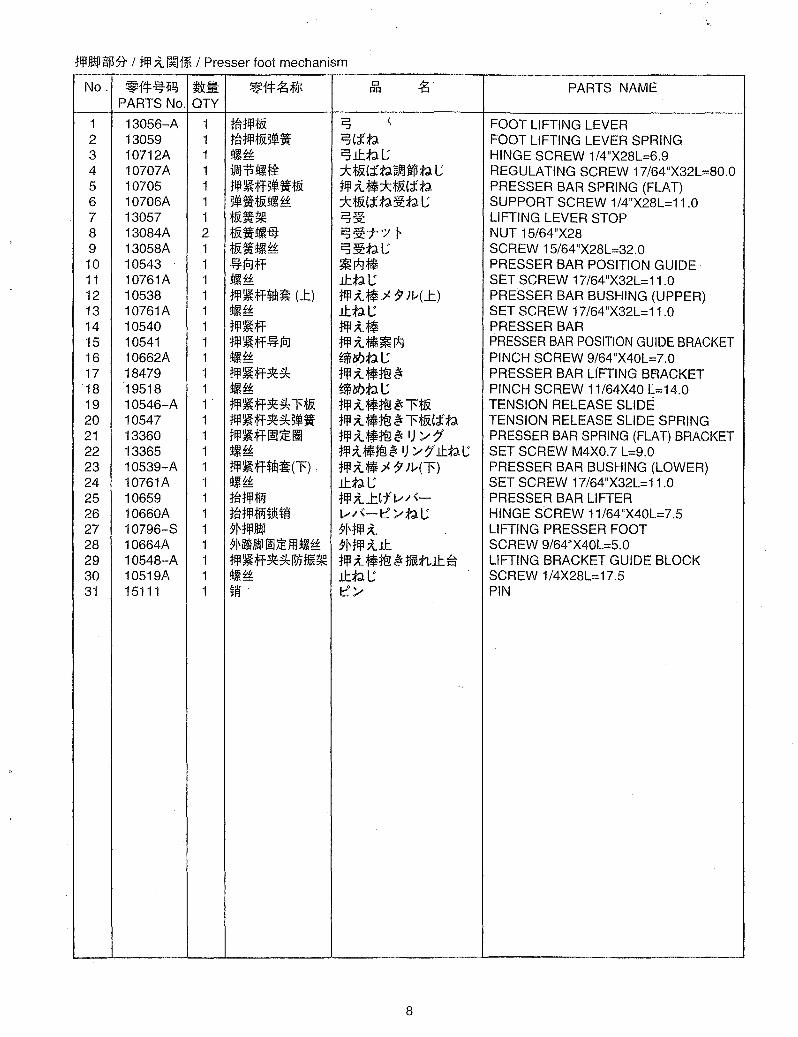
1 13056-A 1 tMljlfR i:5 \ FOOT LIFTING LEVER 2 13059· 1 t~tlflt&5~. i:5(itl FOOT LIFTING LEVER SPRING 3 10712A 1 !I!J!~ i:5lttll; HINGE SCREW 1/4"X28L=6.9 4 10707A 1 ~:P!llJiti ::k:f&(itl~ffdjptll; REGULATING SCREW 17/64"X32L=80.0 5 10705 1 tljl~;fB~.t& tlfl ~:f!::k:f&'itl PRESSER BAR SPRING (FLAT) 6 10706A 1 5~.t&!I!J!~ ::k:f&(j:'tl:¥ttll; SUPPORT SCREW 1/4"X28L=11.0 7 13057 1 fR.~ i:5:¥t LIFTING LEVER STOP 8 13084A 2 t&.!lIJi& i:5:¥t"t"y ~ NUT 15/64"X28 9 13058A 1 t&.!lIJi~ i:5:¥ttll; SCREW 15/64"X28L=32.0 10 10543 1 ~jcJff ~r*J:f! PRESSER BAR POSITION GUIDE 11 10761A 1 !lL'~ lttll; SET SCREW 17/64"X32L=11.0 12 10538 1 tljl~ff$ib~ (..t) tlfl~:f!;{ 7 Ji,;(-t) PRESSER BAR BUSHING (UPPER) 13 10761A 1 !I!J!~ lttll; SET SCREW 17/64"X32L=11.0 14 10540 1 jlfl~ff tlfl~:f! PRESSER BAR 15 10541 1 tljl~ff~jcJ tlfl~:f!~r*J PRESSER BAR POSITION GUIDE BRACKET 16 10662A 1 !I!J!~ ~lsf.>tll; PINCH SCREW 9/64"X40L=7.0 17 18479 1 tljl~ff~#'; tlfl~:f!t§~ PRESSER BAR LIFTING BrlACKET 18 19518 1 !I!J!~ ~lsf.>tll; PINCH SCREW 11/64X40 L=14.0 19 10546-A 1 tljl~ff~#'; l't& tlfl ~ :f!t§ ~ 1':f& TENSION RELEASE SLIDE 20 10547 1 tlfl~ff~#';5~. tlfl ~:f!t§ ~ 1';fR(j:'tl TENSION RELEASE SLIDE SPRING 21 13360 1 tljl~fflE~1I tlfl~:f!t§~ I) ,//j' PRESSER BAR SPRING (FLAT) BRACKET 22 13365 1 !I!J!~ jljl X :f!t§ ~ I) '/7"lt:td.l; SET SCREW M4XO.7 L=9.0 23 10539-A 1 tljl ~ff$ib~(l') tlfl ~:f! ;( 7 Ji,;(l') PRESSER BAR BUSHING (LOWER) 24 10761A 1 !I!J!~ lttll; SET SCREW 17/64"X32L=11,0 25 10659 1 t~tljl;Wi tlfl~-ttfv/'- PRESSER BAR LIFTER 26 10660A 1 t~tljl;Wi~ll!t~ v/'-l:: '/tll; HINGE SCREW 11/64"X40L=7.5 27 10796-S 1 jl\jljl/l!!l jl\tlfl~ LIFTING PRESSER FOOT 28 10664A 1 91\~/l!!I ~JEjIHlm~ )Nlfl~lt SCREW 9/64"X40L=5.0 29 10548-A 1 tljl~ff~#';I~H~~ tlfl ~:f!t§ ~ fmnlt ~ LIFTING BRACKET GUIDE BLOCK 30 10519A 1 !I!J!~ lttll; SCREW 1/4X28L=17.5 31 15111 1 t~ l::'/ PIN
8

~*4tJlf~ / .L~~) 1*l1¥ / Upper feed mechanism
9
4 1
1 •
~25
10
29
.
19 ___ ,~ __ L1-26
9
..tj!*4:rflft.! I ..tj! 'J I~HW; I Upper feed mechanism
No. ~14=-l.%1i~ ~; ~14=.t~ 0 .t PARTS NAME I'm
PARTS No. QTY
1 19425 1 1i!flll 1i,IIl' LIFTING ROCK SHAFT 2 19515 1 1i!flll~JJiffJ 1i ,1Ill::' ::..- tl L:\ SCREW STUD 1/4X28 3 19516 1 1i!flll ~JJi ffJ ~li-Ht 1i'IIll::'::..-tlL:T';/ I- NUT 1/4X28 4 10514 2 1i~tll!flll~ 1i'IIl;f. ~}v LIFTING ROCK SHAFT BUSHING 5 19419 1 J:l'Cl*~Ii*~~~ ..t T:fJb.j!UE9")v7 LIFTING ECCENTRIC CONNECTING CRANK 6 19420 1 ~li~ ~tlL: PINCH SCREW 1/4X28 L=16.0 7 10775 1 ..tIf*fi!i ii;IT-!Il~ ~ ..tiIUE lJ ';/ F ~)ttl L: HINGE SCREW 7/32X32 8 10703 1 m~ r; ';/y-v- WASHER 9 10774 1 ..tIf*fi!iii;IT-~ ..tjl*E lJ ';/ !-" /" 17
0
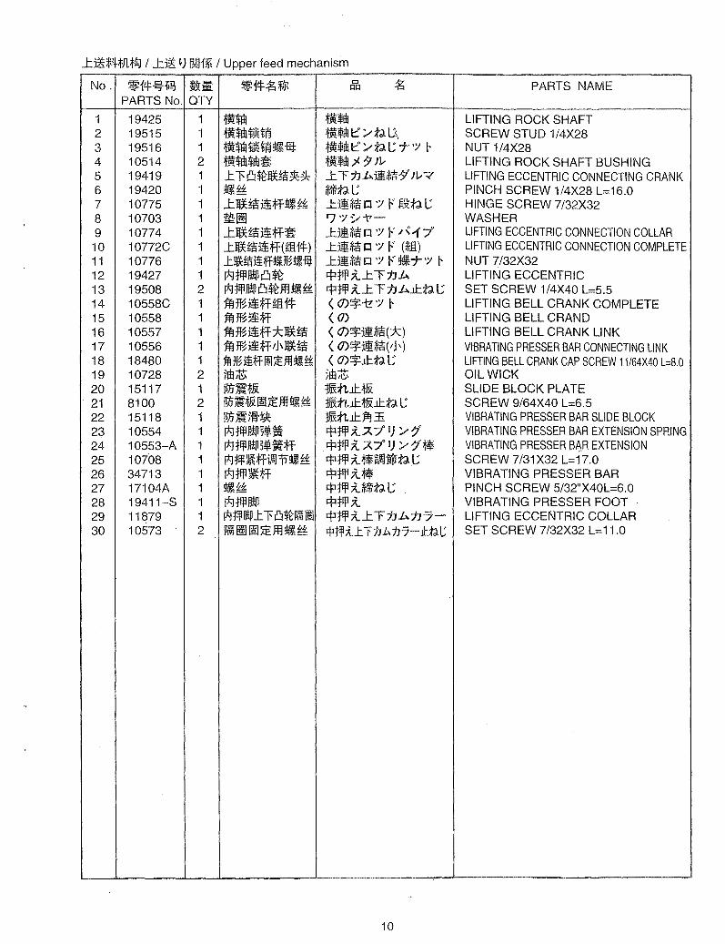
LIFTING ECCENTRIC CONNECTION COLLAR 10 10772C 1 ..tIf* fi!i ii;ff (ffi.14=) J::jI*E lJ ';/ F (*'£1) LIFTING ECCENTRIC CONNECTION COMPLETE 11 10776 1 .tijHjlj~ff~%!B.I£t ...tjl*E lJ ';/ F ~T ';/ I- NUT 7/32X32 12 19427 1 pg:tIflIltP~~ ~ tlfl ;t...t T:fJ b. LIFTING ECCENTRIC 13 19508 2 pgjIflIl!PCl~.ffl!llli~ ~tlfl;t...t T:fJ b.J.l:.tl L: SET SCREW 1/4X40 L=5.5 14 10558C 1 jMf~ ii ;IT-ffi.14= < O)~-t! ';/ I- LIFTING BELL CRANK COMPLETE 15 10558 1 j.itJf~ ii;IT- (0) LIFTING BELL CRAND 16 10557 1 jfl~ii;IT-*If*fi!i ( O)~jI*E(*) LIFTING BELL CRANK LINK 17 10556 1 jfl H~ ii;IT- I J \ If* fi!i < O)~jI*E(/H VIBRATING PRESSER BAR CONNECTING LINK 18 18480 1 1fl%~fflEJ:E:ffl!B.I~ < o)~J.l:.tlL:· LIFTING BELL CRANK CAP SCREW 11/64X40 L=8.0 19 10728 2 lEB~ 5fi1 ;t!; OIL WICK 20 15117 1 ~~t.& :}hHtlJ:J& SLIDE BLOCK PLATE 21 8100 2 ~~:t&IEJ:E:.ffl~I~ WtLJ.l:. t&J.l:.tl L: SCREW 9/64X40 L=6.5 22 15118 1 ~~}ff:ttc WtLJ.l:.1EJ::E VIBRATING PRESSER BAR SLIDE BLOCK 23 10554 1 pg jlfl IltP 5~ it ~tlfl;tA7° I) ::"-7< VIBRATING PRESSER BAR EXTENSION SPRING 24 10553-A 1 pg tlfl IltP 5~ it;IT- ~tlfl;tA7° I) ::"-7"~' VIBRATING PRESSER BAR EXTENSION 25 10i08 1 pgjijl~;ffWaJ:P~~ ~tlfl ;t~,~~tP:tJ L: SCREW 7/31X32 L=17.0 26 34713 1 pgtlfl~;IT- ~tlfl;t~ VIBRATING PRESSER BAR 27 17104A 1 ~li~ ~:tlfl ;t~:tJ L: PINCH SCREW 5/32"X40L=6.0 28 19411-S 1 pg flfllltP ~tlfl;t VIBRATING PRESSER FOOT 29 11879 1 I*Jjljlll!P.t l' Cl~~1 ~tlfl ;t...tT::hb.::h7- LIFTING ECCENTRIC COLLAR 30 10573 2 ~Wi ~ IE J:E: .FIHli ~ $t~ xl. T 1J.b.1J 7-ll:tl C SET SCREW 7/32X32 L=11.0
10
23 22 24
27 J 16
1314 15
I
I
I I 12
I
i~J frI~ ....
~ f1i ~-~ 3 4 2 1
9 6 10 11
11
~*4~il'B7t I ~ ~) ~~1* I Feed shaft mechanism
No. ~14~fi!3 ~E3 ~14~~ 0 ~ PARTS NAME .!!iI1!. IU:!
PARTS No. QTY
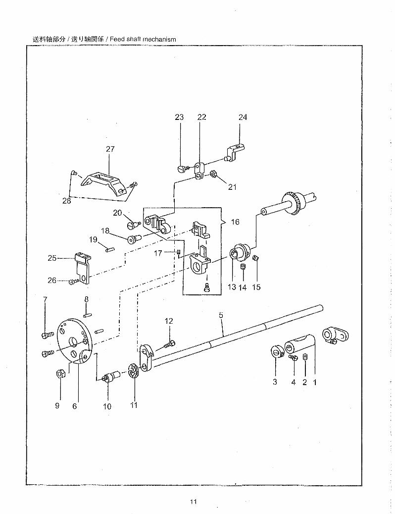
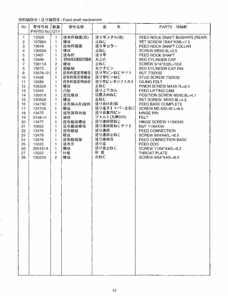
1 13029 1 ~1'iJ;ff~~(J§) ~ 'J ~7- 9 J!.-(1i) FEED ROCK SHAFT BUSHING (REAR) 2 10766A 1 !III~ .1l:.tll; SET SCREW 15/64"X28L=7.0 3 13049 1 ~1'iJ;ff~~ ~')~t.J7- FEED ROCK SHAFT COLLAR 4 13033A 1 !III~ .1l:.tll; SCREW M5XO.8L=2.5 5 13467 1 ~1'iJ;ff ~')~ FEED ROCK SHAFT 6 13466 1 ~;f1!tJL~J141Q~iEI!lOOt& n"i~t: BED CYLINDER CAP 7 13011A 2 !ll~~ .1l:.tll; SCREW 3/16"X32L=10.0 8 13073 2 IrufIHfj n7"91::~ BED CYLINDER CAP PIN 9 13076-01 1 ~:ffiff~;iEm9IJm ~')~I::~tlI;T'/' I- ~UT 7/32X32 10 13468 1 ~:ffiff~;iEm9IJ~ ~'J~I::~tll; STUD SCREW 7/32X32 11 13080 1 ~:ffiff ~;iE m ;£11 {g ~'J~I::~*~7 Ilv I- OILING FELT 12 10532A 1 !III~ .1l:.tll; PINCH SCREW M4XO.7L=8.5 13 13340 1 Cl*t ~ 'J ..t1't.J.b. FEED LIFTING CAM 14 13031A 1 :IE 1:iL!ijl~ . 1:iLlibj,:l5f.>tll; POSITION SCREW M5XO.8L=4.7 15 13085A 1 !II,~~ .1l:.tll; SET SCREW M5XO.8L=4.3 16 13473C 1 ~ 1'iJ ~(4liom 14 ~ 'J ~(4};~O~H3. FEED BASE COMPLETE 17 13472A 1 !III~ ~ 'J tiiA I- '/' /{-.1l:.tll; SCREW M2.5X0.45 L=6.5 18 13475 1 ~ 1'iJ ~ ~ tcJ tfj ~'J~~pgl::~ HINGE PIN 19 0148-H 1 jEll~ 7 Xlv I- (n~3X5) FELT 20 13477 1 ~ 1'iJl£Ui'i!ijl ~~ ~ 'JllUM.litll; HINGE SCREW 11/64X40 21 10652 1 ~1'iJ~~!II1 £3: ~ '))!Ui'i~tlt; 7'/' I- NUT 11/64X40 22 13476 1 ~1'iJ~~ ~ 'J JI*s FEED CONNECTION 23 13479 1 !III~ ~ 'J JI*s.1l:.tl t; SCREW 9/64X40L =6.5 24 13478 1 ~1'iJ~~~ ~')JI~~ FEED CONNECTION BASE 25 13020 1 ~1'iJ3f ~ 'J tii FEED DOG 26 200181A 1 !III~ ~ 'J ilij.1l:.tlt; SCREW 11/64"X40L=6.2 27 13022 1 Hf& ~t t& THROAT PLATE 28 13023A 2 !III~ .1l:.tll; SCREW 9/64"X40L=8.0
12
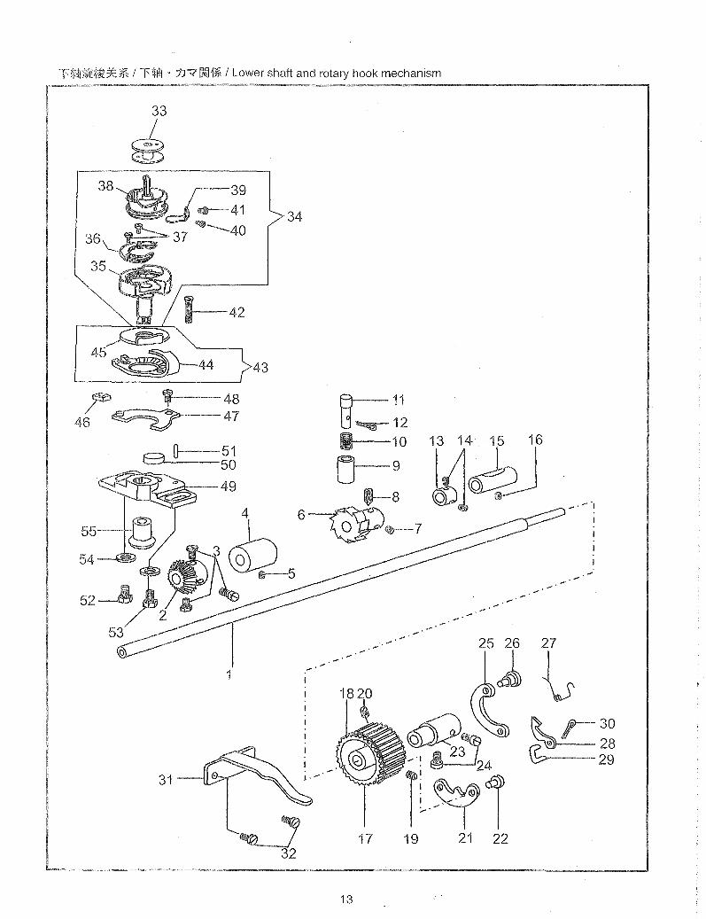
-T'%illh~~&** / l'~i±l . jJ7~1* / Lower shaft and rotary hook mechanism
33
~ 38
37
,---39 .--41 ~--40
r .--48 46 ~ 47
8"--O---~ci ~~~
-±--49
55-
1
31
34
43
~ 32
... "
..... 25 26
G~ q~G . 23
tl~1 17 19 21 22
13
.....
27
\s ~r30 (bCi) 28
29

l'$tI!litEt&=*:* I l'~m . ::t.F?OO1Wt I Lower shaft and rotary hook mechanism
No. ~14=.!f5-1i~ ~; ~14=4';~ Cl 4'; PARTS NAME I:!I:!
PARTS No. OTY
1 13456 1 l'$tI! l'~m HOOK DRIVING SHAFT 2 13032 1 :*:$:tlH~ :*:::f.t'- HOOK DRIVING GEAR 3 13033 3 ~IH: :*:::f.t'-lttlL SET SCREW 13/64X32 L=5.0 4 13028 1 l'~$llr~cmJ) l'~ril ;;l )1 )HiW) HOOK DRIVING SHAFT BUSHING(FRONT) 5 10764A 1 ~JE~tI!~ffl ~J ~~ l'~m;;l )1 )HiW)lt(5l)tl C' SET SCREW 15/64"X28L=4.5 6 13362 1 wJR*i JR HOOK DRIVING SHAFT LOCK RATCHET 7 23634 1 JE1.il:!lt~~~ 1.il: fI' 5* (5l) tl L POSITION SCREW 1/4/28 L=6.0 8 23637 1 JEf.il:~J~~ It(5l)tlL SET SCREW 1/4X28L =7.5 9 13045 1 Ei:w.~ JlflL*)1:/±~ LOCK STUD SOCKET 10 13047 1 Ei:iil. 5~ ji flfl L *)1:/ A7° I) :/7' LOCK STUD SPRING 11 13046 1 Ei:iil. flflL*)1:/ LOCK STUD 12 15076 1 9fP$f!j ~tl ~J t:::/ PIN 13 13049 1 1'~1il~f,).i1l l'~m1J"7- HOOK DRIVING SHAFT COLLAR 14 13050A 2 ~I~~ l'~m n"7-lt SET SCREW M5XO.8L=4.5 15 13029 1 l'~Iil~!Il~(J§) l'~m;;l )1 )H1~) HOOK DRIVING SHAFT BUSHING (REAR) 16 10767A 1 ~Iil~ ~ JE ffl ~,~ ~~ l'~m;;l)1 )H1~)lttl L SET SCREW 15/64"X28L=4.5 17 13424-01 1 l' J1l.';;$i l'''')L- I- 7°- 1)- LOWER PULLEY 18 10574 1 J1l. -:; $iIil' 7°-1) -I) ://f PULLEY SPRING FLANGE 19 10581 1 ~If:~ lttl L (tl~:@: t:::/ ffl) SET SCREW 7/32X32 L=7.0(FOR LEVER HINGE STUD 20 10581 1 ~Jf:~ lttl L (I::: :/ ~ t:: :/ ffl) SET SCREW 7/32X L=7.0(FOR HINGE PIN) 21 10616 1 1'$i:t.:E~ l' "')L- I- -I) -jl~:@: SAFETY CLUTCH LOCKING LEVER 22 10613 1 Jl~$f!j 1'-"]v ~ f-I) -Hl~.:t::;,- LEVER HINGE STUD 23 10611 1 J.:E~/L\~ l'''')L- I- 7°-1) -;tt~ SAFETY CLUTCH COLLAR 24 10612 2 ~Jf:~ It(5l)tlL SCREW 1/4X32 L=10.5 25 10615 1 l'$N&ji 1'-")1;" 7'_1) -tN(itl SAFETY CLUTCH LOCKING LEVER SPRING 26 10614 1 $f!j I:::/,~t:::/ HINGE PIN 27 10619 1 1'*i5~ji l'''''v r i-I) "::"7-.7'1) '/7" THROW-IN LATCH SPRING 28 10617 1 l'$i/J\~ l' "')1; " -I) -/J\JR SAFETY CLUTCH RATCHET 29 10618 1 1'*i/N5Hi1i 1'-")v" f -I) -!j\:lIf.ti" RATCHET CONNECTION LINK 30 10620 1 l'*i9fP$f1i 1'",}v" 7'_1) -j1(~ ~J t::'/ THROW-IN LATCH PIN 31 13054 1 iFoJ:p &: *$t m JE i1t )11 ~ :/7'7°1/- I- BELT TIMING PLATE 32 10597 2 ~J~ lttlL , SCREW 1/8X40 L=3.3 33 10656 1 t&/L' *1:::':/ BOBBIN 34 13086C 1 litE t& (ffi 14=) 1r-;r(ifJl) HOOOK COMPLETE 35 13086-01 1 jl'1ifft& jl'11< HOOK 36 16291-03 1 I*J 1ifft& flfl ~ t:&: I*J 1J<flfl~ HOOK GIB 37 16407-04 2 tlflll,UJ~~ I*J n<:rlfl xlttl L HOK GIB SCREW 38 10655-02 1 l*J1ifft& I*Jn< BOBBIN CASE 39 16291-07 1 imJ~;lB~ji * ~J~Ff,;·t'tl BOBBIN CASE TENSION SPRING 40 16291-08 1 5~ji~JEffl~l~ * ~~.:r(;f tl ~.:rtl L TENSION REGULATING SCREW 41 16407-11 1 ~JE~Jf:~ * ~~.:r(;;ftllttl L SCREW 42 13087A 1 1ifft&~JE~Jti 1J<lt HOOK SET SCREW 9/64"X40L=21.0 43 13041C 1 5HH';JMf;ftt1.&(£El i!f) 7j--7°":T- . n<tN(ifJl) OPENER& HOOK WASHER COMPLETE 44 13041 1 t&~?H~~ *I:::'/'7-A/j-"7°j-- BOBBIN CASE OPENER 45 13042 1 1ifft&tN n<t:&: HOOK WASHER 46 13040 1 m-t:&: IJ\ 1EJ ~1i] BOBBIN CASE LEVER ECCENTRIC BLOCK 47 13038 1 ?H~ ~imJ lH:&: ?j-_"7
0
j--~~Htpt:&: LEVER FULCRUM W/STUD 48 8040 1 ~Jf:~ lttlL SCREW 9/64X40 L=8.0 49 13464 1 1ifft&~ n<±~ HOOK SADDLE 50 13081 1 ilflm "7 I)L- I- OIL FELT 51 0148-A 1 llflm "7 I;L- I- (1L~3X1 0) OIL FELT 52 13717A 1 ~,~*i:(*) lttlL (~) SCREW M5XO.8L=16.5 53 13036A 1 ~1*i(~R) lttlL (m) SCREW M5XO.8L=12.0 54 13037 2 mil ry 'y~t'- WASHER 55 13034 1 tj\$:tMi Jj\::f.--'r'- HOOK BEVEL GEAR
14
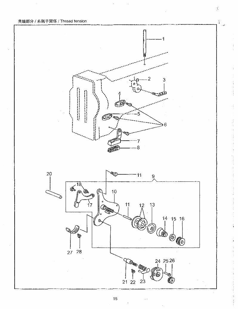
~~$* / ~iFaJTmJ1* / Thread tension
1----1
20 1----11 9
r£,18~ u~ c.
n7 0 11 12 13
~-- ~ 14 15 16
27 28
15
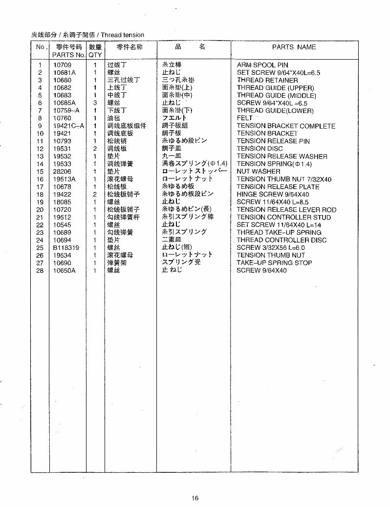
~~:!HIMt I ~ifalT~~ I Thread tension
No. ~f*~1i!?J ~Ji ~f*~~ Cl ~ PARTS NAME QQ
PARTS No. QTY
1 10709 1 tt~T *:.U:~ ARM SPOOL PIN 2 10681A 1 !lI~ .tttlC SET SCREW 9/64"X40L=6.5 3 10680 1 '='~Ltt~T .=. ?~L*tI~ THREAD RETAINER 4 10682 1 L~T im*ID(L) THREAD GUIDE (UPPER) 5 10683 1 Ift~T im*ID(Ift) THREAD GUIDE (MIDDLE) 6 10685A 3 !lI~ .tttlC SCREW 9/64"X40L =6.5 7 10759-A 1 l'~T im*ID(l') THREAD GUIDE(LOWER) 8 10760 1 lIE t9: 7 .I}I; I- FELT 9 19421C-A 1 ifal ~1iH'&ffi 1* ~T:f.&~ TENSION BRACKET COMPLETE 10 19421 1 ifal~J€£:f.& ~T:f.& TENSION BRACKET 11 10793 1 ;f't~ti'4 *11>~1si)~1:::/" TENSION RELEASE PIN 12 19531 2 ifal~:f.& ~T.llll. TENSION DISC 13 19532 1 W:lt j:r,-.llll. TENSION RELEASE WASHER 14 19533 1 ifal~5~. i{Cj!{i;A, 7° I) /" ~{( <P 1.4) TENSION SPRING( <P 1 .4) 15 28206 1 W:lt IJ-v':; I- A I- ,:;/"~- NUT WASHER 16 19513A 1 ~:re!lliij: IJ-v':; I- T':; r TENSION THUMB NUT 7/32X40 17 10678 1 ;f't~:f.& *11>~1si):f.& TENSION RELEASE PLATE 18 19422 2 ;f't~:f.&ti'4T * 11> ~ Isi):f.&$ji I::: /" HINGE SCREW 9/64X40 19 18085 1 !lI~ .tttlC SCREW 11 164X40 L=8.5 20 10720 1 ;f't~:f.&ti'4T fMP~Isi)I:::/"(~) TENSION RELEASE LEVER ROD 21 19512 1 ~~5~.ff *51 A, 7° I) /"~l~ TENSION CONTROLLER STUD 22 10545 1 !lI~ .tttlC SET SCREW 11/64X40 L=14 23 10689 1 ~~5~. * 51 A 7° I) /" 7' THREAD TAKE-UP SPRING 24 10694 1 W:lt =I.llll. THREAD CONTROLLER DISC 25 B118319 1 IjjJ~ lttlC (m) SCREW 3/32X56 L=6.0 26 19534 1 ~:re!lliij: IJ-v':; r T':; r TENSION THUMB NUT 27 10690 1 5~.~ A,7° I) /"7"~ TAKE-UP SPRING STOP 28 10650A 1 !lI~ It tl.C SCREW 9/64X40
16

f""-'
®--12 t 10 14, _ ~'I-~ ___ : ._'''''''..1
.",....-'-
_.-.-' .- ....... -_.-.-
W 26
1--25
~ 24
7
1
17

1~~~jf** I r,',/ 71Ul1* I Feed reversing lever .
No. ~1*~1iI!, !J&""' ' .§Ii! ~1*~ffR 0 ~ PARTS NAME j:!j:!
PARTS No. QTY
1 13403C 1 ~1P~;jf5,9:~EH* ' ~ ') 0 ''/ F 5,9: (*JO FEED ROD (5 PARTS)COMPLETE 2 10722 1 1m'§: 7 Ill.- ~ OIL FELT 3 10723 1 1m'§:tEf1. 7 Ill.- HEf1x. I. OIL FEL T STOPPER 4 19508 2 !llJiH: ~ t) :tJ.b.Jttll " SET SCREW 1/4X40 L=5.5 5 11069 1 1m'§: ~ ') 0 ''/ F ~I*J 7 Ill.- ~ OIL FELT 6 27177 1 !llJiH: Jttll (:*) SCREW M5XO.8 L=16.0 7 13412 2 1m'§: 7 Ill.- ~ OIL FELT 8 10597 2 !llJiH: 7 Ill.- ~ Jttll SCREW 1/8X40 L=3.3 9 13407 1 l*J*rll~ l!;tl~7ll.- SUPPORTING BUSHING 10 13387 1 _Urljl:P*rll~ .L~ill ~ ~ }Hr:prB~) ARM SHAFT BUSHING (MIDDLE) 11 19415 1 !llJiH: Jttll SCREW 1/4X28 L=20.0 12 4113 1 !llJita Jtj-''/ l- NUT 1/4X28 13 10571A 1 !ll.!f:H: Jttll SET SCREW 17/64"X32L=20.0 14 10725 1 1m'§: 7 Ill.- l- OlL FELT 15 13415 1 -=p.;@JfEMi:!i!llJi ii Lr\-t:/tll FEED REGULATING LEVER 16 13418 1 ~mirolHJi ~ £)~fp*'& STITCH LENGTH PLATE 17 7041A 4 !llJiH: JttlI; SCREW 1/8X40L=7.0 18 13417 1 ~miroTi~ ~t)~fp/\17° FEED ADJUSTING PIPE 19 13416 1 *:f:t:!llJita 0-1/ ''/ l- KNURLING TOOL 20 8157 1 ~!Jl. A,7° I) //f SPRING 21 8158 1 IN:* *-ll.- BALL 22 18027 1 ~mimJ:fj;@J ~ t) ~fpl//-\- FEED REVERSE LEVER 23 18028 2 !llJiH: Jttl I; (/J\) SET SCREW M5XO.8 L=5.0 24 10806 1 -=p.;j:i7i M 1ft S!Jl. /'\''/71//-\- A, 7° I) //f FEED REVERSE LEVER SPRING 25 13419 1 S!Jl.ti A,7° I) /7' ji~ SPRING HOOK 26 15076 1 1fD¥i:!i l!;IJ t:/ PIN
18

1lf1Jj~$:5t / 11Jj~OO1%. / Accessories
5 4 11
I
3 2 1
8
15
16
9
19
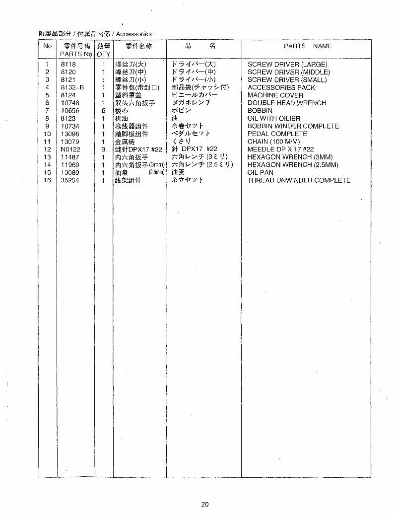
1l11Jl1~ifB* I {'.tJll~~1~ I Accessories
No. ~f*~1i~ !J&i;. ~f*~~ t:l ~ PARTS NAME t:ll=l
PARTS No. QTY
1 8118 1 !lIJ~7J(:k) F 74 /',-(:k) SCREW DRIVER (LARGE) 2 8120 1 !lIJ~7J(~) F 74 /~-(I:j:l) SCREW DRIVER (MIDDLE) 3 8121 1 !llJ~7J(ll\) F 74 /~-(tj\) SCREW DRIVER (SMALL) 4 8132-B 1 ~f*g(ilH11J) ifB~~(T-V "/ .y{'.t) ACCESSORIES PACK 5 8124 1 ~*4fl~ 1::::' '='-Jv7J/'- MACHINE COVER 6 10748 1 XX ~ /\ jij ti -=¥ ;l1J';fV ~T DOUBLE HEAD WRENCH 7 10656 6 ~/L' . *I::::'~ BOBBIN 8 8123 1 *JUm jm OIL WITH OILIER 9 10734 1 ~~Hffi1* *~-t!')1 I- BOBBIN WINDER COMPLETE 10 13098 1 ~ Jl!P;fJj ffi f* '" :$0 v -t! ')I r PEDAL COMPLETE 11 13079 1 :&JlIfii < ~ ~) CHAIN (100 M/M) 12 N0122 3 £iHtDPX17 #22 illt DPX17 #22 MEEDLE DP X 17 #22 13 11487 1 p;j /-, jij !& -=¥ /,1fJ v /'T (3 ~ I)) HEXAGON WRENCH (3MM) 14 11969 1 p;j 7'\" jij :tJi -=¥ (3mm) /,1fJ v ~T (2.5 ~ I)) HEXAGON WRENCH (2.5MM) 15 13089 1 jm1i (2.5mm) jm~ OIL PAN 16 35254 1 ~~ffi1* *iL -t! ')I r THREAD UNWINDER COMPLETE
20
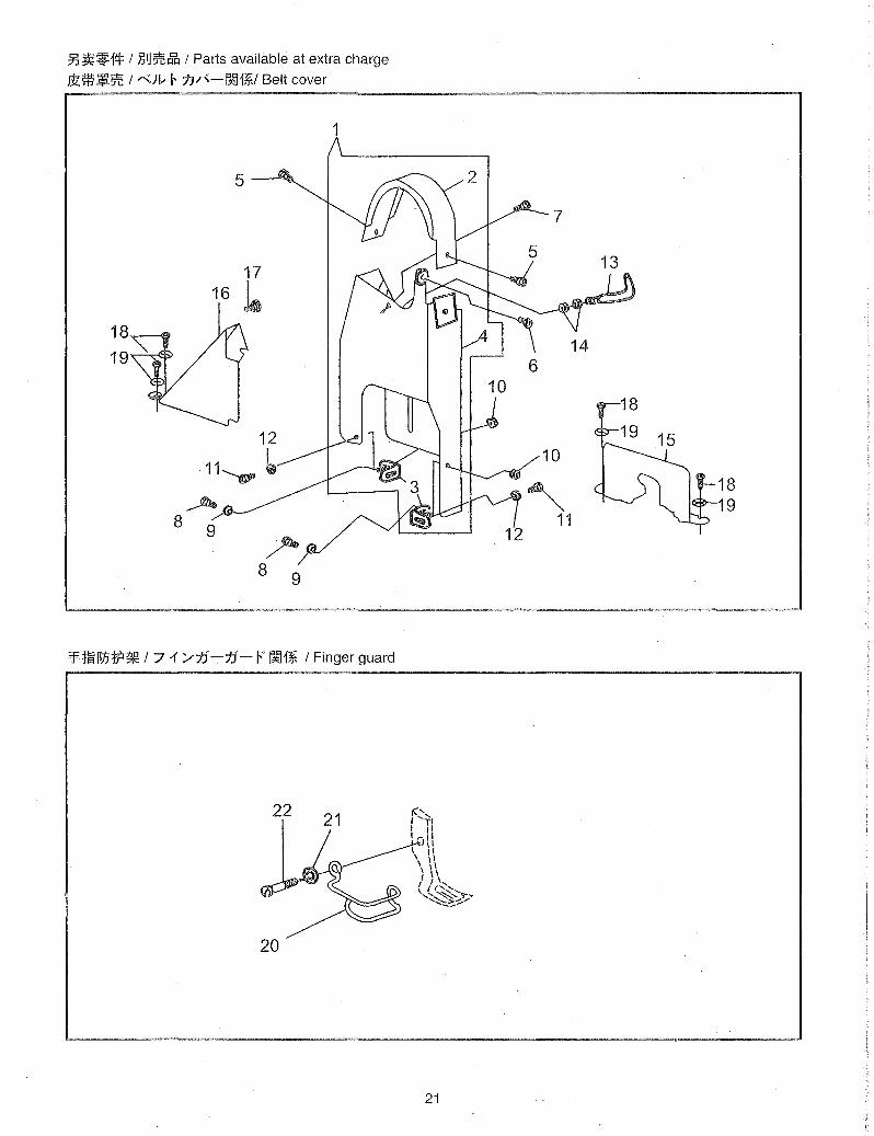
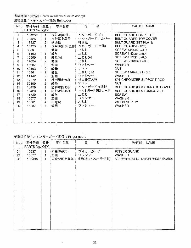
33~~1* /l.:IJ~~ / Parts available at extra charge
Bl*~:% / '-"::JJ... r 7.V\-OO1%/ Belt cover
18
19
5---
17
16 .b
12 I
11~ ii)
-' 8 9
~ 8 9
1
-'ft~~JJtP~ / 7 l' '/t1-t1- F ~1* / Finger guard
22
l 21
20
21
18 19
§5~~14= / )5IJ~~ / Parts available at extra charge
$:*.!l~ / "'}\.; r 7:J/"-~1~/ Belt cover
No. ~14=~1i~ ~;;. ~14=~~ CJ ~ I=Ul
PARTS No. QTY
1 13425C 1 &:*.!l(m14=) r.;:}\.; r 1]"- F (*Jl) 2 13426 1 $:-:;.!l-t.!l~ r.;:}\.; r 1J- ". -t7:)/'-3 13427 2 tUJ.J*.& fmWJ*-& 4 13425 1 &: * IVH? .!l(:t 1* r.;:}\.; r jJ- F (*1*) 5 6339 2 !I!~~ J.t.:td.L; 6 11162 1 !I!~~ J.t.:td.L; 7 10559 1 !I!~~(A) J.t.:td. L; (A) 8 14024 2 ~~£: J.t.:td. L; .
9 16287 2 ~lm IJ 'Y y"\7-10 50103 2 !I!~iij: -j-'Y r 11 10561 2 !I!~~ J.t.:td. L; CF) 12 11142 2 11l:lm IJ 'Y y"\7-13 17372 1 ~i9!~H~fTI:;jf t~:±jH3t;tl! 14 50409 2 ~iij: -j-'Y r 15 13429 1 1lJJ:f? ~ ttWJ i& r.;:}\.; r j]"- F fmWJ:f'& 16 13428 1 1lJJ:f? ~ ttWJ *-& "')/; r t.f- F -rmM:1j'- F 17 11830 1 ~~ J.t.:td.L;
18 10677 1 ~lm IJ'Yy"\7-19 15081 4 ;iJ'~~ *:td.L; 20 16287 4 ~lm IJ'Yy"\7-
-¥:j:~IlJJ:f?~ 171 ';,/jJ-j]"- F OO~ I Finger guard
No. ~14=~1i!?J ~:Ii: ~f4=~~ CJ ~ 1=11=1
PARTS No. QTY
21 10937 1 -¥:j:~IlJJ:f?~ 71t.1"-j)"-F 22 10677 1 ~lm IJ'YY"\7-23 10749A 1 ~~~~~!I!,~~ ~H~kll:(71 '/1:J-ti- '" fll )
22
PARTS NAME
BELT GUARD COMPLETE BELT GUADRD TOP COVER BELT GUARD SET PLATE BELT GUARD(BODY) SCREW 1/8X44 L=4.0 SCREW 3.4X36 L=5.4 SCREW 4.5X32 L=8.0 SCREW 3/16X32 L=9.5 WASHER NUT SCREW 11/64X32 L=6.5 WASHER SYNCHRONIZER SUPPORT ROD NUT BELT GUARD (BOTTOM)SIDE COVER BEL T GUARD (BOTTOM)COVER SCREW WASHER WOOD SCREW WASHER
PARTS NAME
FINGER GUARD WASHER SCREW 9/64"X40L=11.5(FOR FINGER GUARD)

CO SEW CONSOLIDATED SEWING MACHINE CORPo
CONSEW INT'L LTD NoYoNoYoUoS.Ao TOKYO JAPAN
WWW.CONSEW.COM