22. Free Fall Valve Pg1-11
12
The FEL Valves range of Free Fall Fire Valves are suitable for installation in either horizontal or vertical pipe work, and are designed to provide a positive, 100% shut off when used as a fuel isolating valve. Free Fall Valves may also be used as a fuel ‘dump’ valve, whereby the valve will open on actuation. A standard Free Fall Valve assembly comprises of a valve, lever and weight, together with a fitting kit. All standard valves are manufactured in cast iron to ASTM A126 Gr B and are approved by both the American Gas Association and Canadian Gas Association, as well as being ‘UL’ Listed. All valves are suitable for use with fuel oils and gases at pressures up to 14 bar. Valves with screwed connections have bsp parallel threads, whilst flanged valves are available with either BS 4504 PN 16 flange drillings or to ANSI 125. FEL Free Fall Fire Valves are also available with carbon or stainless steel body and plug materials. Standard Fire Valves are supplied with a ‘650 Lubricating Compound’, which is a gener al purpose sealant, suitable for hydrocarbons, other Lubricating Compounds are available, if you are unsure of the suitability of the 650 Compound for your specific application, please contact us for further details. Free Fall Valves may be actuated mechanically or electrically. The majority of installations use mechanical actuation by fusible link, therefore each Fire Valve is supplied with a Fire Valve Kit, available in three sizes, Small (15 to 50mm nb valves), Medium (65 to 100mm nb val ves) and Large (125 to 200mm nb valves). Kits contain varying numbers of Pulley Wheels, Stainless Steel Cable, Fusible Links, Warning Signs, Cable Connectors and Tension Springs, any of which may be purchased as individual products. Electrically actuated Fire Valve systems utilise a standard valve, lever and weight, however an electrical Release System is used, essentially, allowing actuation by making or breaking an electrical circuit. The installation of a valve mounted Mercury Switch, Electro Mechanical Release or Wall Mounted Changeover Switch may provide remote signalling of the Fire Valve status, or allow direct switching of electrical equipment where applicable. Data Sheets: Screwed Valves Flanged Valves Price List Fire Valve Solution Centre Double click on any of the highlighted ‘Key Words’ for additional information. Free Fall Fire Valves, Supplied by FEL Valve s Ordering Information Tel: 01565 733137. Fax 01565 733841. E-mail: [email protected] Web: www.felvalves.com Valves Ltd., 96 Pickmere Lane, Wincham, Northwich, Cheshire, UK. CW9 6EB
-
Upload
roshan-shanmughan -
Category
Documents
-
view
39 -
download
2
description
Fire valve
Transcript of 22. Free Fall Valve Pg1-11

Free Fall Fire Valve #DS001 02/02/2009 Page Page 1 of 12
The FEL Valves range of Free Fall Fire Valves are suitable for installation in either horizontal or verticalpipe work, and are designed to provide a positive, 100% shut off when used as a fuel isolating valve.Free Fall Valves may also be used as a fuel ‘dump’ valve, whereby the valve will open on actuation.
A standard Free Fall Valve assembly comprises of a valve, lever and weight, together with a fitting kit.
All standard valves are manufactured in cast iron to ASTM A126 Gr B and are approved by both theAmerican Gas Association and Canadian Gas Association, as well as being ‘UL’ Listed. All valves aresuitable for use with fuel oils and gases at pressures up to 14 bar. Valves with screwed connectionshave bsp parallel threads, whilst flanged valves are available with either BS 4504 PN 16 flange drillingsor to ANSI 125.
FEL Free Fall Fire Valves are also available with carbon or stainless steel body and plug materials.
Standard Fire Valves are supplied with a ‘650 Lubricating Compound’, which is a general purposesealant, suitable for hydrocarbons, other Lubricating Compounds are available, if you are unsure of thesuitability of the 650 Compound for your specific application, please contact us for further details.
Free Fall Valves may be actuated mechanically or electrically. The majority of installations usemechanical actuation by fusible link, therefore each Fire Valve is supplied with a Fire Valve Kit, availablein three sizes, Small (15 to 50mm nb valves), Medium (65 to 100mm nb valves) and Large (125 to200mm nb valves). Kits contain varying numbers of Pulley Wheels, Stainless Steel Cable, Fusible Links,Warning Signs, Cable Connectors and Tension Springs, any of which may be purchased as individualproducts.
Electrically actuated Fire Valve systems utilise a standard valve, lever and weight, however an electricalRelease System is used, essentially, allowing actuation by making or breaking an electrical circuit. Theinstallation of a valve mounted Mercury Switch, Electro Mechanical Release or Wall MountedChangeover Switch may provide remote signalling of the Fire Valve status, or allow direct switching ofelectrical equipment where applicable.
Data Sheets: Screwed Valves Flanged Valves Price List Fire Valve Solution Centre
Double click on any of the highlighted ‘Key Words’ for additional information.
Free Fall Fire Valves,S u p p l i e d b y F E L V a l v e s
Ordering InformationTel: 01565 733137. Fax 01565 733841. E-mail: [email protected] Web: www.felvalves.comValves Ltd., 96 Pickmere Lane, Wincham, Northwich, Cheshire, UK. CW9 6EB

2
Screwed Free Fall Fire Valves Flanged Free Fall Fire Valves
20-001 1/2" 20-012 2"
20-003 3/4" 20-014 2 1/2"
20-005 1" 20-016 3"
20-007 1 1/4" 20-017 4"
20-009 1 1/2" 20-018 5"
20-011 2" 20-019 6"
20-013 2 1/2" 20-020 8"
Electro-Thermal Fusible Links
20-170 71C 160F
20-171 84C 194F
20-172 96C 205F
20-173 121C 218F
20-174 167C 330F
20-175 184C 360F
20-176 228C 440F
Mercury Changeover Switches
20-150 Single Phase 10 amp
20-151 Three Phase 10 amp
Electro Magnetic Valve Release Mechanisms
20-162 24V dc Emag
20-163 110V ac Emag
20-164 230V ac Emag
20-165 24V dc Emag2 c/w Volt Free Contacts
20-166 110V ac Emag2 c/w Volt Free Contacts
20-167 230V ac Emag2 c/w Volt Free Contacts
Fire Valve Control Panels
20-180 230V ac Input/230V ac Output
20-181 230V ac Input/110V ac Output
20-182 24Vdc Input/24V dc Output
20-183 230V ac Input/Battery Backed 24V dc Output
Spare Valve Sealing Compound
20-050 '650' For Oil & Gas
20-051 '750' for High Temp Oil & gas
Push Buttons & Break Glass Call Points
20-155 230Vac/24Vdc Emergency Knock Off
20-156 230Vac/24Vdc Knock Off c/w Key Release
20-196 Red Break Glass Call Point
20-197 Yellow Break Glass Call Point
20-198 Green Break Glass Call Point
Remote Alarms
20-195 Red 230V ac 150mm Bell
20-196 Red 24V dc 150mm Bell
20-265 230V ac Audio/Visual Alarm
Battery Trickle Chargers
20-185 230V ac input/3.2a/hr 24V dc Output
20-186 230V ac Input/6.0a/hr 24V dc Output
Screwed Free Fall Fire Valves Flanged Free Fall Fire Valves
20-001 1/2" 20-012 2"
20-003 3/4" 20-014 2 1/2"
20-005 1" 20-016 3"
20-007 1 1/4" 20-017 4"
20-009 1 1/2" 20-018 5"
20-011 2" 20-019 6"
20-013 2 1/2" 20-020 8"
Soldered Fusible Links
20-090 71C 160F
20-091 92C 197F
20-092 104C 220F
20-093 127C 260F
20-094 143C 290F
Mercury Changeover Switches
20-150 Single Phase 10 amp
20-151 Three Phase 10 amp
Release Mechanisms
20-160 Manual Quick Release
20-161 ElectroManual Release
Free Fall Kit Components
20-070 1/4" BSP x 40mm Pulley Wheel
20-071 M12 Male x 40mm Pulley
20-074 1/4" BSP x 40mm Anchor
20-075 M12 Male x 40mm Anchor
20-077 1/4" BSP Backplate
20-078 M12 Backplate
20-080 9m 316 Stainless Steel Cable
20-081 30m 316 Stainless Steel Cable
20-082 150m 316 Stainless Steel Cable
20-101 Tension Spring
20-107 Caution Sign for stainless cable
Spare Free Fall Kits
20-060 'Small' For 1/2" to 2" Valves
20-061 'Medium' for 2 1/2" to 4" Valves
20-062 'Large' for 5" to 8" Valves
Spare Valve Sealing Compound
20-050 '650' For Oil & Gas
20-051 '750' for High Temp Oil & gas

3

4

5

6

7
8

9
10
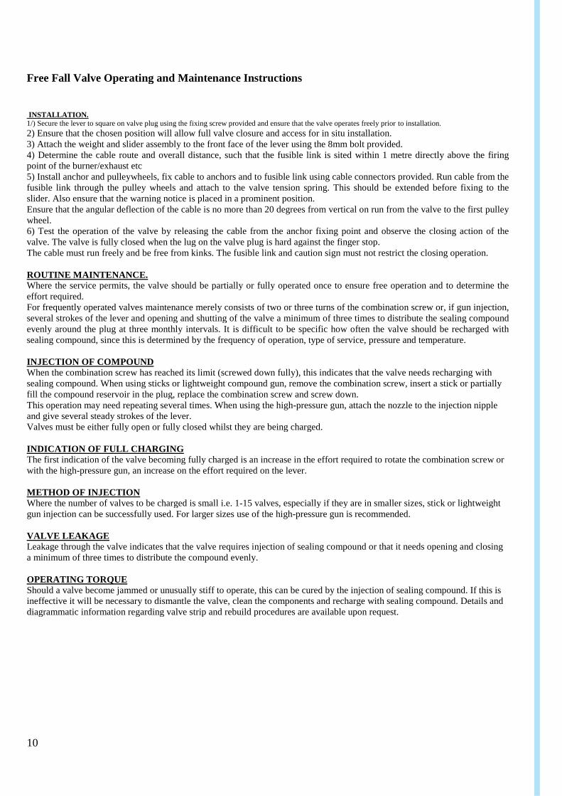
Free Fall Valve Operating and Maintenance Instructions
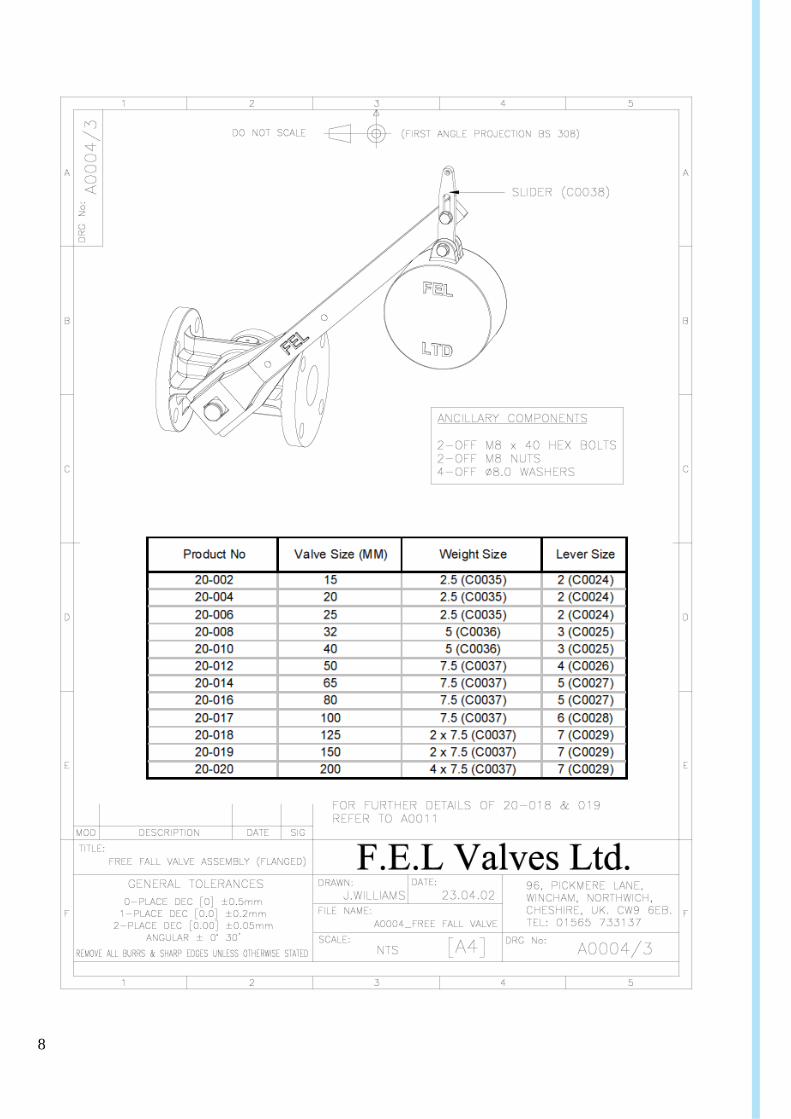
INSTALLATION.1/) Secure the lever to square on valve plug using the fixing screw provided and ensure that the valve operates freely prior to installation.
2) Ensure that the chosen position will allow full valve closure and access for in situ installation.3) Attach the weight and slider assembly to the front face of the lever using the 8mm bolt provided.4) Determine the cable route and overall distance, such that the fusible link is sited within 1 metre directly above the firingpoint of the burner/exhaust etc5) Install anchor and pulleywheels, fix cable to anchors and to fusible link using cable connectors provided. Run cable from thefusible link through the pulley wheels and attach to the valve tension spring. This should be extended before fixing to theslider. Also ensure that the warning notice is placed in a prominent position.Ensure that the angular deflection of the cable is no more than 20 degrees from vertical on run from the valve to the first pulleywheel.6) Test the operation of the valve by releasing the cable from the anchor fixing point and observe the closing action of thevalve. The valve is fully closed when the lug on the valve plug is hard against the finger stop.The cable must run freely and be free from kinks. The fusible link and caution sign must not restrict the closing operation.
ROUTINE MAINTENANCE.Where the service permits, the valve should be partially or fully operated once to ensure free operation and to determine theeffort required.For frequently operated valves maintenance merely consists of two or three turns of the combination screw or, if gun injection,several strokes of the lever and opening and shutting of the valve a minimum of three times to distribute the sealing compoundevenly around the plug at three monthly intervals. It is difficult to be specific how often the valve should be recharged withsealing compound, since this is determined by the frequency of operation, type of service, pressure and temperature.
INJECTION OF COMPOUNDWhen the combination screw has reached its limit (screwed down fully), this indicates that the valve needs recharging withsealing compound. When using sticks or lightweight compound gun, remove the combination screw, insert a stick or partiallyfill the compound reservoir in the plug, replace the combination screw and screw down.This operation may need repeating several times. When using the high-pressure gun, attach the nozzle to the injection nippleand give several steady strokes of the lever.Valves must be either fully open or fully closed whilst they are being charged.
INDICATION OF FULL CHARGINGThe first indication of the valve becoming fully charged is an increase in the effort required to rotate the combination screw orwith the high-pressure gun, an increase on the effort required on the lever.
METHOD OF INJECTIONWhere the number of valves to be charged is small i.e. 1-15 valves, especially if they are in smaller sizes, stick or lightweightgun injection can be successfully used. For larger sizes use of the high-pressure gun is recommended.
VALVE LEAKAGELeakage through the valve indicates that the valve requires injection of sealing compound or that it needs opening and closinga minimum of three times to distribute the compound evenly.
OPERATING TORQUEShould a valve become jammed or unusually stiff to operate, this can be cured by the injection of sealing compound. If this isineffective it will be necessary to dismantle the valve, clean the components and recharge with sealing compound. Details anddiagrammatic information regarding valve strip and rebuild procedures are available upon request.
11
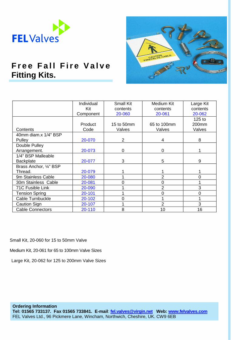
Small Kit, 20-060 for 15 to 50mm Valve
Medium Kit, 20-061 for 65 to 100mm Valve Sizes
Large Kit, 20-062 for 125 to 200mm Valve Sizes
F r e e F a l l F i r e V a l v eFitting Kits.
IndividualKit
Component
Small Kitcontents20-060
Medium Kitcontents20-061
Large Kitcontents20-062
ContentsProductCode
15 to 50mmValves
65 to 100mmValves
125 to200mmValves
40mm diam.x 1/4" BSPPulley 20-070 2 4 8Double PulleyArrangement. 20-073 0 0 11/4" BSP MalleableBackplate 20-077 3 5 9Brass Anchor, ¼” BSPThread. 20-079 1 1 19m Stainless Cable 20-080 1 2 030m Stainless Cable 20-081 0 0 171C Fusible Link 20-090 1 2 3Tension Spring 20-101 1 0 0Cable Turnbuckle 20-102 0 1 1Caution Sign 20-107 1 2 3Cable Connectors 20-110 8 10 16
Ordering InformationTel: 01565 733137. Fax 01565 733841. E-mail: [email protected] Web: www.felvalves.comFEL Valves Ltd., 96 Pickmere Lane, Wincham, Northwich, Cheshire, UK. CW9 6EB

12
Fire Valve sealants are specifically formulated for various service applications. Selection of sealants inaccordance with the sealant recommendation chart below is essential for the maximum performance andefficiency of a Free Fall Fire Valve. The sealant chart designates the applicable service conditions forwhich the various sealants are suitable.
Sealant NumbersTemperatureRange C Colour Principle Usage Solvent
Stick FEL Code From To6 20-046 0 135 Grey Hot Water Service Naptha
400 20-047 -8 60 Red Acids & Alkalis Naptha450 20-048 -8 60 White Food products Naptha
600 20-049 -20 60 BrownGeneral HydrocarbonServices Perchlorethylene
650 20-050 -30 85 GreenHydrocarbons, LPG &Natural Gas Chlorethane
711 20-055 -25 85 Clear Internal Combustion Fuels Chlorethane
750 20-051 -8 205 BlackAsphalt & Hot OilServices Naptha
800 20-056 -25 122 WhiteHydrocarbons &Aromatics Perchlorethylene
900 20-057 -20 122 BlackHydrocarbons, Aromatics& Asphalt Perchlorethylene
The above temperature ranges are quoted at maximum pressure, i.e. 14 bar, temperatures exceedingthese values are permissible. Please contact FEL Valves for applications that may fall outside of thedesignated temperature range.
Valve and Sealant Sizes/Quantities
Valve Sizes, nb.Sealant StickDiameter
Number of Sticks perBox
15mm to 50mm 3/8" 1250mm to200mm 1/2" 12
F r e e F a l l F i r e V a l v eLubricating Compounds
Ordering InformationTel: 01565 733137. Fax 01565 733841. E-mail: [email protected] Web: www.felvalves.comFEL Valves Ltd., 96 Pickmere Lane, Wincham, Northwich, Cheshire, UK. CW9 6EB