219272664 s-parameters
27
Microwave Engineering Prof. N.V. Langhnoja Page 1 S-PARAMETERS 1. INTRODUCTION: Power dividers and directional couplers are passive microwave components used for power division or power combining, as illustrated in Figure 7.1. In power division, an input signal is divided into two (or more) output signals of lesser power, while a power combiner accepts two or more input signals and combines them at an output port. The coupler or divider may have three ports, four ports, or more, and may be (ideally) lossless. Three-port networks take the form of T-junctions and other power dividers, while four-port networks take the form of directional couplers and hybrids. Power dividers usually provide in-phase output signals with an equal power division ratio (3 dB), but unequal power division ratios are also possible. Directional couplers can be designed for arbitrary power division, while hybrid junctions usually have equal power division. Hybrid junctions have either a 90 ◦ or a 180◦ phase shift between the output ports. A microwave junction is an interconnection of two or more microwave components as shown in figure 2 below. MICROWAVE JUNCTION LOAD LOAD LOAD SOURCE 2 1 3 4
-
Upload
manish-arora -
Category
Education
-
view
1.486 -
download
0
Transcript of 219272664 s-parameters

Microwave Engineering
Prof. N.V. Langhnoja Page 1
S-PARAMETERS
1. INTRODUCTION:
Power dividers and directional couplers are passive microwave components used for
power division or power combining, as illustrated in Figure 7.1.
In power division, an input signal is divided into two (or more) output signals of
lesser power, while a power combiner accepts two or more input signals and
combines them at an output port.
The coupler or divider may have three ports, four ports, or more, and may be (ideally)
lossless.
Three-port networks take the form of T-junctions and other power dividers, while
four-port networks take the form of directional couplers and hybrids.
Power dividers usually provide in-phase output signals with an equal power division
ratio (3 dB), but unequal power division ratios are also possible.
Directional couplers can be designed for arbitrary power division, while hybrid
junctions usually have equal power division. Hybrid junctions have either a 90◦ or a
180◦ phase shift between the output ports.
A microwave junction is an interconnection of two or more microwave components as
shown in figure 2 below.
MICROWAVE
JUNCTION LOAD
LOAD
LOAD
SOURCE
2
1
3
4

Microwave Engineering
Prof. N.V. Langhnoja Page 2
2. THE SCATTERING MATRIX:
The low frequency circuits can be represented in two port networks and
characterized by their parameters i.e. impedances, admittances, voltage gain,
current gain, etc. All these parameters relate total voltages and currents at the
two ports.
In addition, a practical problem exists when trying to measure voltages and
currents at microwave frequencies because direct measurements usually
involve the magnitude (inferred from power) and phase of a wave traveling in
a given direction or of a standing wave. Thus, equivalent voltages and
currents, and the related impedance and admittance matrices, become
somewhat of an abstraction when dealing with high-frequency networks.
So at microwave frequency the logical variables used are travelling waves
with associated powers, rather than total voltages and total currents. These
logical variables are called as S- parameters.
So in microwave analysis, the power relationship between the various ports of
microwave junction is defined in terms of parameters, called as S-parameters
or scattering parameters.
As the microwave junction is a multiport junction, the power relationship
between the various ports are defined in terms of matrix form, and called as S
matrix, which a square matrix giving all the power combinations between the
input port and output ports.
Equipments are not readily available to measure total voltage and current at
the ports of the network for microwave range. Also it is difficult to achieve
short and open circuits on a large bandwidth of frequencies.
The relationship between the scattering matrix and input/output powers at
different ports can be obtained for N port microwave junction as shown in
figure2.
an is the amplitude of voltage wave incident on port n, while bn is the
amplitude of the reflected voltage wave from port n.
MICROWAVE
JUNCTION
a2
2
1
3
n
a1
b1
a3
b3
an
bn
b2
N port Microwave network
Microwave Engineering
Prof. N.V. Langhnoja Page 3
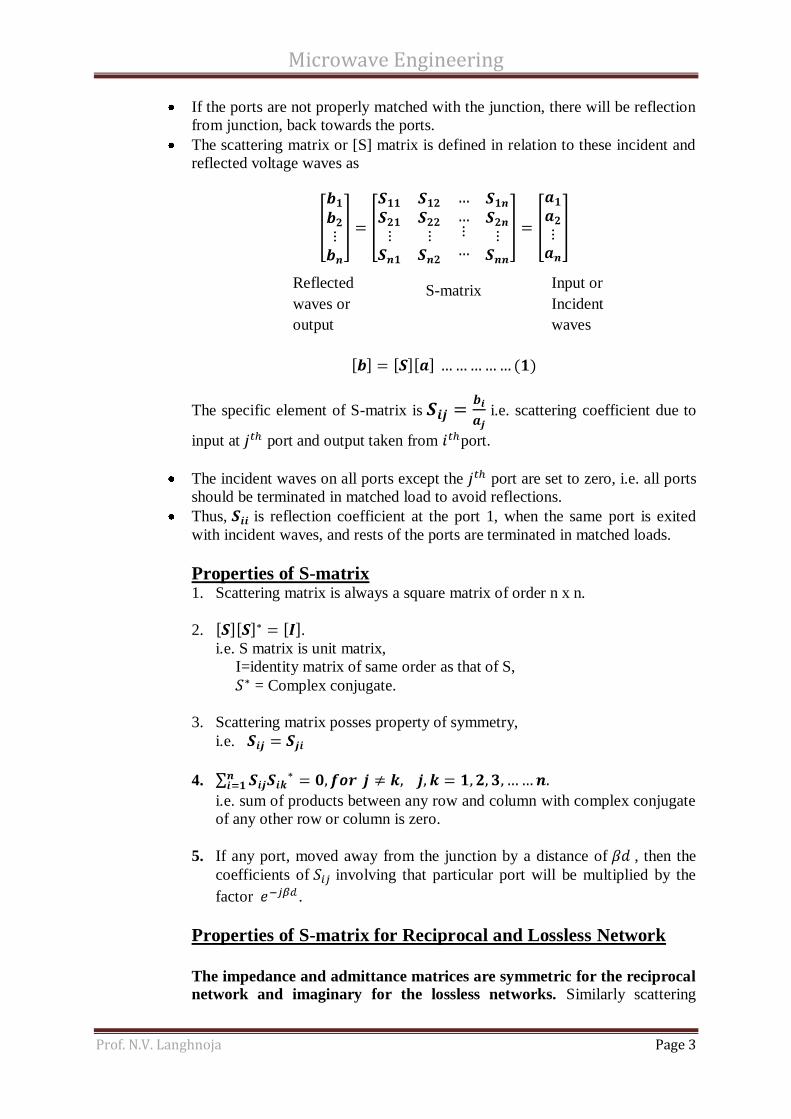
If the ports are not properly matched with the junction, there will be reflection
from junction, back towards the ports.
The scattering matrix or [S] matrix is defined in relation to these incident and
reflected voltage waves as
The specific element of S-matrix is i.e. scattering coefficient due to
input at port and output taken from port.
The incident waves on all ports except the port are set to zero, i.e. all ports
should be terminated in matched load to avoid reflections.
Thus, is reflection coefficient at the port 1, when the same port is exited
with incident waves, and rests of the ports are terminated in matched loads.
Properties of S-matrix 1. Scattering matrix is always a square matrix of order n x n.
2. .
i.e. S matrix is unit matrix,
I=identity matrix of same order as that of S,
= Complex conjugate.
3. Scattering matrix posses property of symmetry,
i.e.
4.
i.e. sum of products between any row and column with complex conjugate
of any other row or column is zero.
5. If any port, moved away from the junction by a distance of , then the
coefficients of involving that particular port will be multiplied by the
factor .
Properties of S-matrix for Reciprocal and Lossless Network
The impedance and admittance matrices are symmetric for the reciprocal
network and imaginary for the lossless networks. Similarly scattering
Reflected
waves or
output
S-matrix Input or
Incident
waves

Microwave Engineering
Prof. N.V. Langhnoja Page 4
matrix i.e. [S] matrix for a reciprocal network is symmetric, and unitary for
lossless network.
Any two port network which will satisfy the following condition is called as
reciprocal network.
Similarly for reciprocal type of network, S matrix id symmetric i.e.
Also this condition can be written in terms of ………(3),
If network is lossless, then the real power delivered to the network, must be
zero.
For lossless network [S] matrix is unitary. Any matrix which will satisfy
is called as unitary matrix. This equation can be modified as
The equation (5) can be written in summation form as,
…………. (6)
Thus , if i = j,
……………. (7)
If
…………… (8)
In words, equation (7) states that the dot product of any column of [S] with the
conjugate of that same column gives unity, while equation (8) states that the
dot product of any column with the conjugate of a different column gives zero
(because columns are ortho normal).

Microwave Engineering
Prof. N.V. Langhnoja Page 5
Example:
the fact that (for short circuit at port 2), we can write as
The equation (ii) gives
Dividing equation (i) by , and using the above result gives the reflection
coefficient seen at port 1 as,
(7)

Microwave Engineering
Prof. N.V. Langhnoja Page 6
Example: David M. Pozar unsolved sum.

Microwave Engineering
Prof. N.V. Langhnoja Page 7
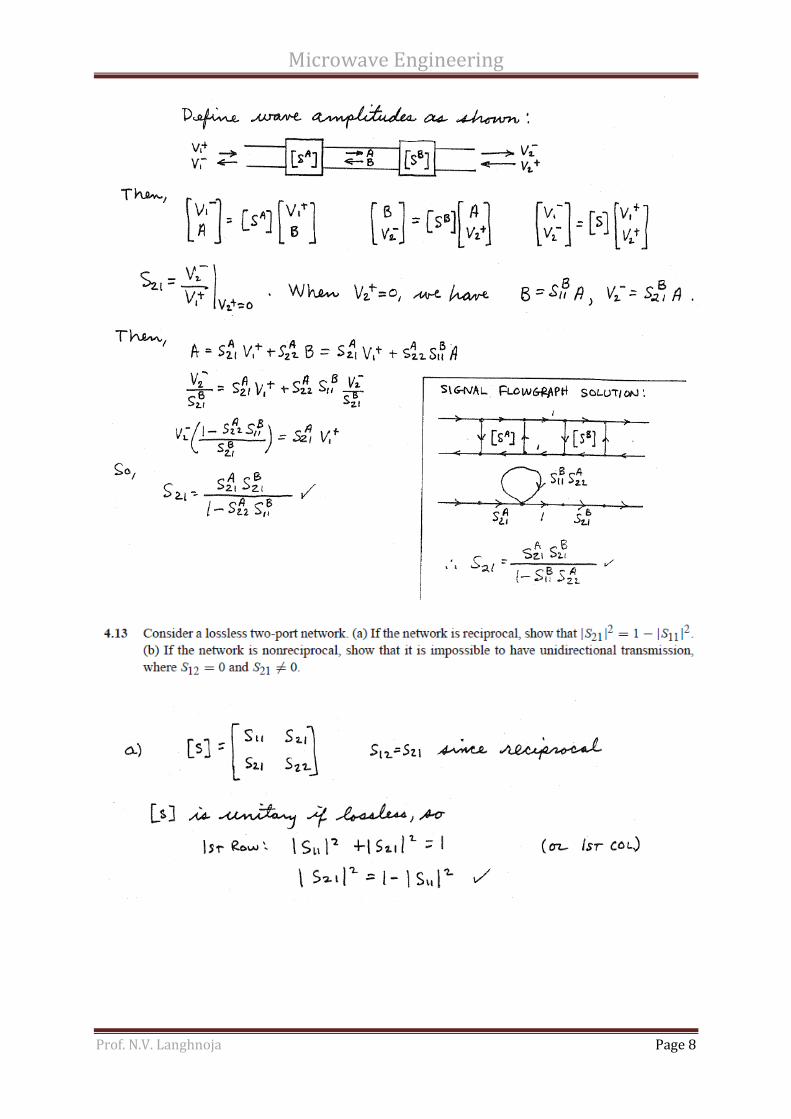
Microwave Engineering
Prof. N.V. Langhnoja Page 8
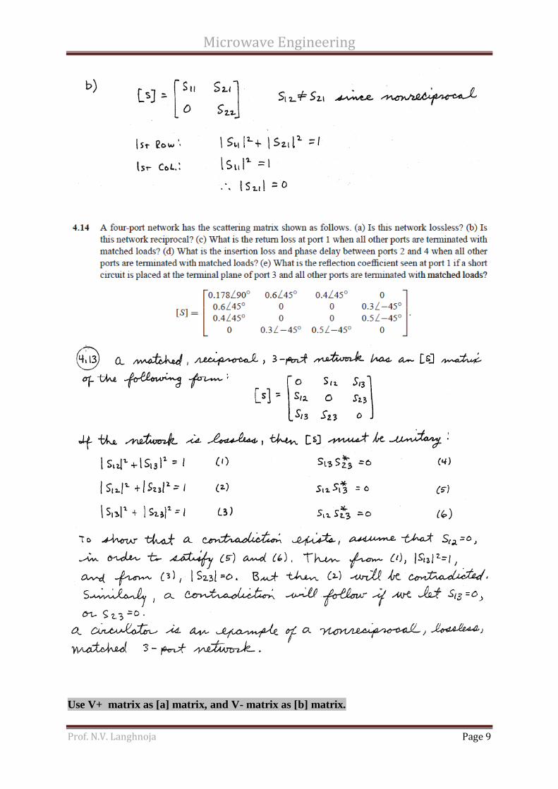
Microwave Engineering
Prof. N.V. Langhnoja Page 9
Use V+ matrix as [a] matrix, and V- matrix as [b] matrix.

Microwave Engineering
Prof. N.V. Langhnoja Page 10
WAVEGUIDE TEES :
Waveguide Tees and couplers are junctions or networks having three or more ports.
Waveguide Tees are used for the purpose of connecting a branch section of waveguide in
series or parallel with the main waveguide.
3. E-Plane TEE JUNCTION (Series Tee):
As shown in figure above is an E-plane Tee junction, as it is an intersection of three
waveguides in the form of alphabet T. Port 1 and 2 are collinear arms while port 3 is
the E arm, which is along the broader dimensions of waveguides.
The T junction is used for power division or power combining.
E-plane Tee is a voltage or series junction – symmetrical about the central arm so that
the signal to be split up (or signals to be combined are taken from it) is fed from it.
However, the problem has more complexities than it appears superficially. This is
because some form of unwanted reflections occurs and it is essentially to provide
some sort of impedance matching to minimize reflections. In fact, E-plane tee may
themselves be used for impedance matching purposes in a manner similar to the short
circuited transmission line stub; where a short circuit at any point is produced by
means of a movable piston.
When the dominant mode is made to propagated through port 3, the outputs
from port 1 and 2 will be at the same amplitude but phase shifted by with
respect to each other. This phase shift is occurring between port 1 and 2 is due to
the change in electric field lines.
As E-plane tee is symmetrical about the central arm, power coming out from port 3, is
proportional to the difference between the power entering from port 1 and 2. When
power entering from port 1 and 2 are in phase opposition, then maximum power
comes out of port 3.
Port 1
Port 3
E arm (side arm)
Port 2
Collinear arm

Microwave Engineering
Prof. N.V. Langhnoja Page 11
Since it is a three port junction the scattering matrix can be derived as follows:
1. [S] Matrix of order 3 x 3.
………………….(9)
2. The Scattering coefficients are
As the waves coming out of the port 1 and 2 of the collinear arm will be
opposite phase and in same magnitude. Negative sign indicates phase
difference.
3. If the port 3 is perfectly matched to the junction
4. For symmetric property
with the above properties, [S] becomes,
5. From unitary property,
From equations (14), and (15), we get
From equation (16),
From equation (17),
Using these values from equation 18, 19 and 20 in equation 14,
Microwave Engineering
Prof. N.V. Langhnoja Page 12
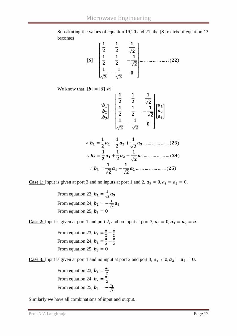
Substituting the values of equation 19,20 and 21, the [S] matrix of equation 13
becomes
We know that,
Case 1: Input is given at port 3 and no inputs at port 1 and 2, .
From equation 23,
From equation 24,
From equation 25,
Case 2: Input is given at port 1 and port 2, and no input at port 3, .
From equation 23,
From equation 24,
From equation 25,
Case 3: Input is given at port 1 and no input at port 2 and port 3, .
From equation 23,
From equation 24,
From equation 25,
Similarly we have all combinations of input and output.

Microwave Engineering
Prof. N.V. Langhnoja Page 13
4. H-Plane TEE JUNCTION (Shunt Tee):
H-plane Tee junction is formed by cutting a rectangular slot along the width of a main
waveguide and attaching another waveguide – the side arm – called as H-arm as
shown in above figure 3.
The port 1 and 2 of the main waveguide are called as collinear ports and port 3 is the
H-arm or side arm.
H-Plane Tee is so-called because the axis of the side arm is parallel to the planes of
the H-field of the main transmission line. As all three arms of H-plane tee lie in the
plane of magnetic field, the magnetic field divides itself into the arms; this is thus a
current junction.
If the H-plane junction is completely symmetrical and waves enter through the side
arm, the waves that leave through the mains arms are equal in magnitude and phase.
Since the electric field is not bent as the wave passes through a H-plane junction, but
merely divides between two arms; fields of same polarity approaching the junction
from the two main arms produce components of electric field that add in side arm.
The effective value of field leaving through the side arm is proportional to the phasor
sum of entering fields.
Maximum energy delivery to side arm occurs when waves entering the junction
through main arms are in phase. The standing wave in the main line then has an anti-
node of electric field at the junction, and a current-node at the same junction. High
energy delivery to a branch line connected to a transmission line at a point of high
voltage and low current takes place if branch lin is connected in shunt with the main
line.
Since it is a three port junction the scattering matrix can be derived as follows:
1. [S] Matrix of order 3 x 3.
………………….(9)
Port 1
Port 3
H arm (side arm)
Port 2
Collinear arm

Microwave Engineering
Prof. N.V. Langhnoja Page 14
2. Because of plane of symmetry of the junction, the Scattering coefficients are
As the waves coming out of the port 1 and 2 of the collinear arm will be
opposite phase and in same magnitude. Negative sign indicates phase
difference.
3. If the port 3 is perfectly matched to the junction
4. For symmetric property
With the above properties, [S] becomes,
5. From unitary property,
From equations (29), and (30), we get
From equation (31),
From equation (32),
Using these values from equation 33, 34 and 35 in equation 29,
Microwave Engineering
Prof. N.V. Langhnoja Page 15
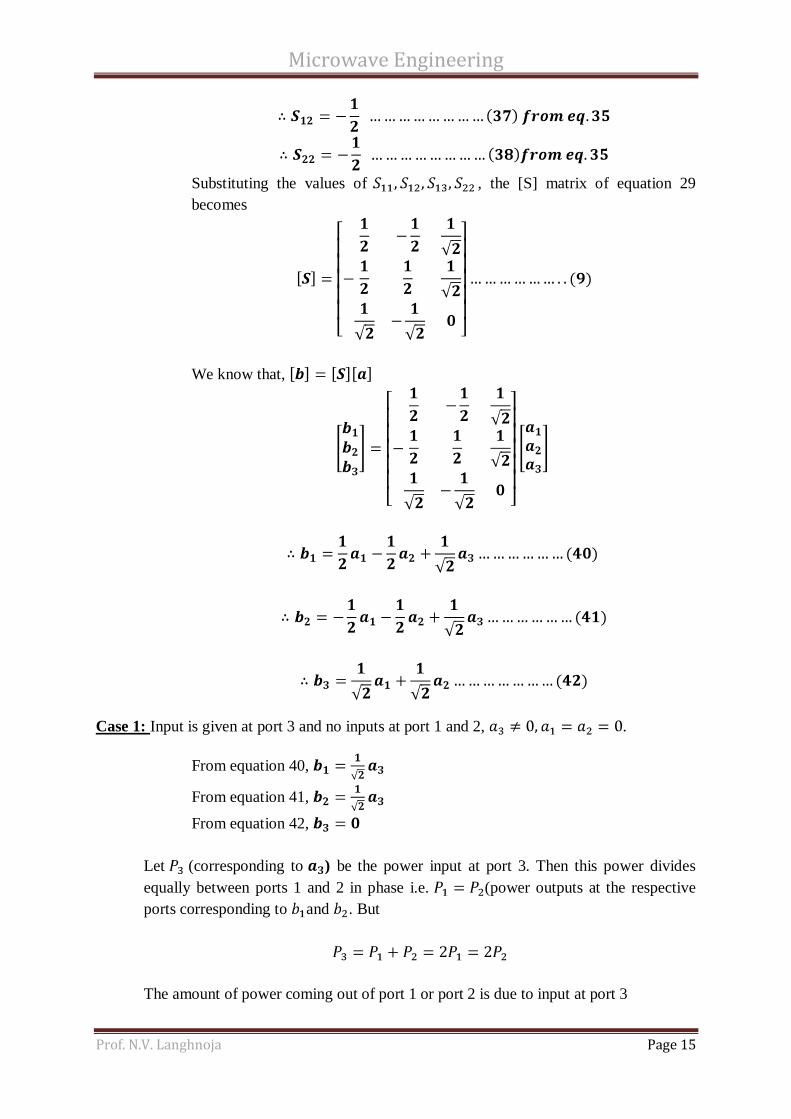
Substituting the values of , the [S] matrix of equation 29
becomes
We know that,
Case 1: Input is given at port 3 and no inputs at port 1 and 2, .
From equation 40,
From equation 41,
From equation 42,
Let (corresponding to ) be the power input at port 3. Then this power divides
equally between ports 1 and 2 in phase i.e. (power outputs at the respective
ports corresponding to and . But
The amount of power coming out of port 1 or port 2 is due to input at port 3

Microwave Engineering
Prof. N.V. Langhnoja Page 16
Hence the power coming out of the port 1 or port 2 is 3 dB down with respect to input
power at port 3; hence the H-plane Tee is called as 3-dB splitter.
Case 2: Input is given at port 1 and port 2, and no input at port 3, .
From equation 40,
From equation 41,
From equation 42,
Input at port 3 is the addition of the two inputs at port 1 and port 2 and these
are added in phase.
5. E-H Plane TEE OR MAGIC TEE:
A magic tee is a combination of E-plane and H-plane Tee.
Magic tee, combines the power dividing properties of both H-plane and E-plane tee,
and has the advantages of being completely matched at all the ports.
If two signals of same magnitude and phase are fed into port 1 and port 2, then outpur
will be zero at port 3 and additive at port 4.
If signal is fed from port 4 (H-arm) then signals divides equally in magnitude and
phase between port 1 and 2 and no signal appears at port 3 (E-arm).
If signal is fed into port 3, then signal divides equally in magnitude, but opposite in
phase at port 1 and 2, and no signal comes out from port 4, i.e. output at port 4 is zero.
This magic occurs, because E-arm causes a phase delay while H-arm causes a phase
advance, resulting into is .
Using the properties of E and H-plane tee, its scattering matrix can be obtained as
follows:
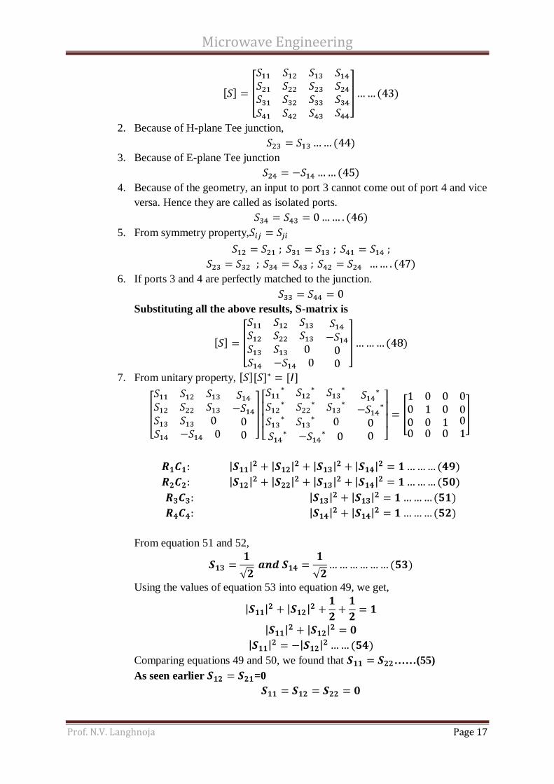
1. [S] Matrix is a 4 x 4 matrix since there are 4 ports.
Microwave Engineering
Prof. N.V. Langhnoja Page 17
2. Because of H-plane Tee junction,
3. Because of E-plane Tee junction
4. Because of the geometry, an input to port 3 cannot come out of port 4 and vice
versa. Hence they are called as isolated ports.
5. From symmetry property,
6. If ports 3 and 4 are perfectly matched to the junction.
Substituting all the above results, S-matrix is
7. From unitary property,
From equation 51 and 52,
Using the values of equation 53 into equation 49, we get,
Comparing equations 49 and 50, we found that ……(55)
As seen earlier =0
Microwave Engineering
Prof. N.V. Langhnoja Page 18
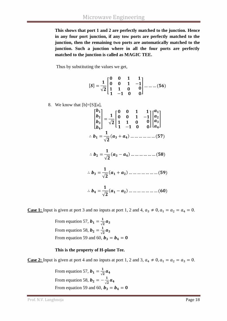
This shows that port 1 and 2 are perfectly matched to the junction. Hence
in any four port junction, if any tow ports are perfectly matched to the
junction, then the remaining two ports are automatically matched to the
junction. Such a junction where in all the four ports are perfectly
matched to the junction is called as MAGIC TEE.
Thus by substituting the values we get,
8. We know that [b]=[S][a],
Case 1: Input is given at port 3 and no inputs at port 1, 2 and 4, .
From equation 57,
From equation 58,
From equation 59 and 60,
This is the property of H-plane Tee.
Case 2: Input is given at port 4 and no inputs at port 1, 2 and 3, .
From equation 57,
From equation 58,
From equation 59 and 60,

Microwave Engineering
Prof. N.V. Langhnoja Page 19
This is the property of E-plane Tee.
Case 3: Input is given at port 1 and no inputs at port 4, 2 and 3, .
From equation 57 and 58 ,
From equation 59
From equation 60,
When power is fed to port 1, nothing comes out of port 2 even though they are
collinear ports (Magic!!). Hence ports 1 and 2 are called as isolated ports.
Similarly an input at port 2 cannot come out at port 1.
Similarly E and H-ports are isolated ports.
Case 4: Equal input is given at port 3 and 4; no inputs at port 1 and 2, .
From equation 57, ,
From equation 58, 59 and 60,
This is called as an additive property.
Case 5: Equal input is given at port 1 and 2; no inputs at port 3 and 4, .
From equation 57, 58, and 60,
From equation 59,
Equal inputs at ports 1 and 2 results in an output port 3 (additive
port)and no output at port 1, 2 and 4. This is similar to case 4.
Applications of magic tee:
1. Measurement of Impedance:
Magic tee has been used in the form of a bridge, as shown in figure below for
measuring impedance.
Microwave source is connected in arm 3
A null detector is connected in arm 4.
The unknown impedance is connected at arm 2.
Standard variable known impedance is connected in arm 1.
Using the properties of magic tee, power from port 3 divides equally in port 1 and 2.

Microwave Engineering
Prof. N.V. Langhnoja Page 20
Now known impedance Z1 and unknown impedance Z2 is not equal to characteristic
impedance Z0. Hence there will be reflections from port 1 and 2 towards the junction.
If and are reflection coefficients, then
The reflection from port 1 is
The reflection from port 2 is
The resultant wave reaching at null port i.e. at port 4 is,
For perfect balancing,
But and
Or
Thus unknown impedance can be measured by adjusting the standard variable impedance till
the bridge is balance and both impedances become equal.
NULL
DETECTOR
MICROWAVE
SOURCE
Z1 Z2
1
4
3
2
Microwave Engineering
Prof. N.V. Langhnoja Page 21
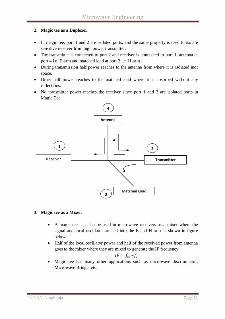
2. Magic tee as a Duplexer:
In magic tee, port 1 and 2 are isolated ports, and the same property is used to isolate
sensitive receiver from high power transmitter.
The transmitter is connected to port 2 and receiver is connected to port 1, antenna at
port 4 i.e. E-arm and matched load at port 3 i.e. H-arm.
During transmission half power reaches to the antenna from where it is radiated inot
space.
Other half power reaches to the matched load where it is absorbed without any
reflections.
No transmitter power reaches the receiver since port 1 and 2 are isolated ports in
Magic Tee.
3. Magic tee as a Mixer:
A magic tee can also be used in microwave receivers as a mixer where the
signal and local oscillator are fed into the E and H arm as shown in figure
below.
Half of the local oscillator power and half of the received power from antenna
goes to the mixer where they are mixed to generate the IF frequency.
Magic tee has many other applications such as microwave discriminator,
Microwave Bridge, etc.
Antenna
Matched Load
Receiver
Transmitter
1
4
3
2

Microwave Engineering
Prof. N.V. Langhnoja Page 22
6. Hybrid Ring:
Rat race (Ring hybrid) is one of the oldest and simplest designs for the
fabrication of a 180 hybrid.
As shown in above figure, it is a ring shape making transmission lines which
compose of three λ/4 line sections and one 3λ/4 line section
To describe the operation, if port 1 is excited, the waves will be transmitted
towards the neighboring ports, port 2 and port4, equally. The other port is
isolated. Two identical waves are transmitted in clockwise and anti-clockwise
direction respectively such that the waves are 180 out of phase at the
interacting port 3. So the voltages are cancelled out and become zero at this
point. The isolated port lets the circuit become a three-port network. Due to
Antenna
Local Oscillator
Mixer Matched Load
1
4
3
2 IF fin
fo

Microwave Engineering
Prof. N.V. Langhnoja Page 23
the impedance of the rat-race ring being constant, the voltages are split equally
to port 2 and port4. However the phase is not identical because the path from
port 1 to port 2 is one-half wavelength which is longer than the path from port
1 and port 4 is 180 . To infer, a table is constructed to illustrate the situation
when different ports are excited.
The scattering matrix can be written as,
7. Directional Coupler:
Directional couplers are flanged, built in waveguide assemblies which can
sample a small amount of microwave power for measurement purposes.
The directional couplers are passive devices used in the field of radio
technology.
These devices fit for the power transmitted through a transmission line to
another port using two transmission lines placed close enough so that the
energy flowing through one of the lines are coupled to each other.
Microwave Engineering
Prof. N.V. Langhnoja Page 24
Directional couplers are defined to be passive microwave components used for
power division.
During the whole process of power division we can notice that the four-port
networks take the form of directional couplers and hybrids.
While directional couplers can be created having in mind the arbitrary power
division, the hybrid junctions have frequently identical power division.
Regarding the hybrid junctions we can take in consideration two situations: a
90° (quadrate) or a 180° (magic-T) phase shift between the output ports.
Looking back at the important steps that have been taken in the HISTORY, is
important to mention that at the MIT Radiation Laboratory in the 1940s, were
invented and characterized a diversity of waveguide couplers, including E-
and H-plane waveguide tee junctions, the Bethe hole coupler, multihole
directional couplers, the Schwinger coupler, the waveguide magic-T, and
several types of couplers using coaxial probes. Another important phase in
development of the couplers is the period between 1950s and 1960s, when it
took place a reinvention of a lot of them to use stripline or microstrip
technology. New types of couplers, like the branch line hybrid, and the
coupled line directional coupler also had benefit of a development, due to the
expanding use of planar lines.
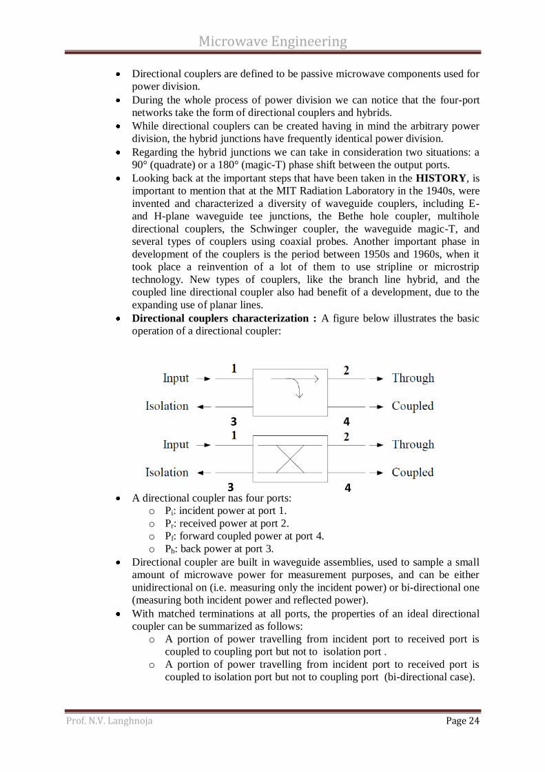
Directional couplers characterization : A figure below illustrates the basic
operation of a directional coupler:
A directional coupler has four ports:
o Pi: incident power at port 1.
o Pr: received power at port 2.
o Pf: forward coupled power at port 4.
o Pb: back power at port 3.
Directional coupler are built in waveguide assemblies, used to sample a small
amount of microwave power for measurement purposes, and can be either
unidirectional on (i.e. measuring only the incident power) or bi-directional one
(measuring both incident power and reflected power).
With matched terminations at all ports, the properties of an ideal directional
coupler can be summarized as follows:
o A portion of power travelling from incident port to received port is
coupled to coupling port but not to isolation port .
o A portion of power travelling from incident port to received port is
coupled to isolation port but not to coupling port (bi-directional case).
4
4
3
3
Microwave Engineering
Prof. N.V. Langhnoja Page 25
o A portion of power incident on isolation port is coupled to receive port
but not to incident port and a portion of power incident on coupling
port is coupled to incident port but not to received port. Also incident
and isolated ports are decoupled as are received and coupled ports.
Coupling factor, C: it is defined as the ratio of the incident power Pi to the
forward power Pr measured in dB.
Directivity, D: the directivity of a D.C. is defined as the ratio of forward
power Pf to the back power Pb, expressed in dB.
Coupling factor is a measure of how much of the incident power is being
sampled while directivity is the measure of how well the directional coupler
distinguishes between the forward and reverse travelling powers.
Isolation, I: it is defined to describe the directive properties of a directional
coupler. It is defined as the ratio of incident power Pi to the back power Pb.
Isolation in dB is equal to the coupling factor plus directivity.
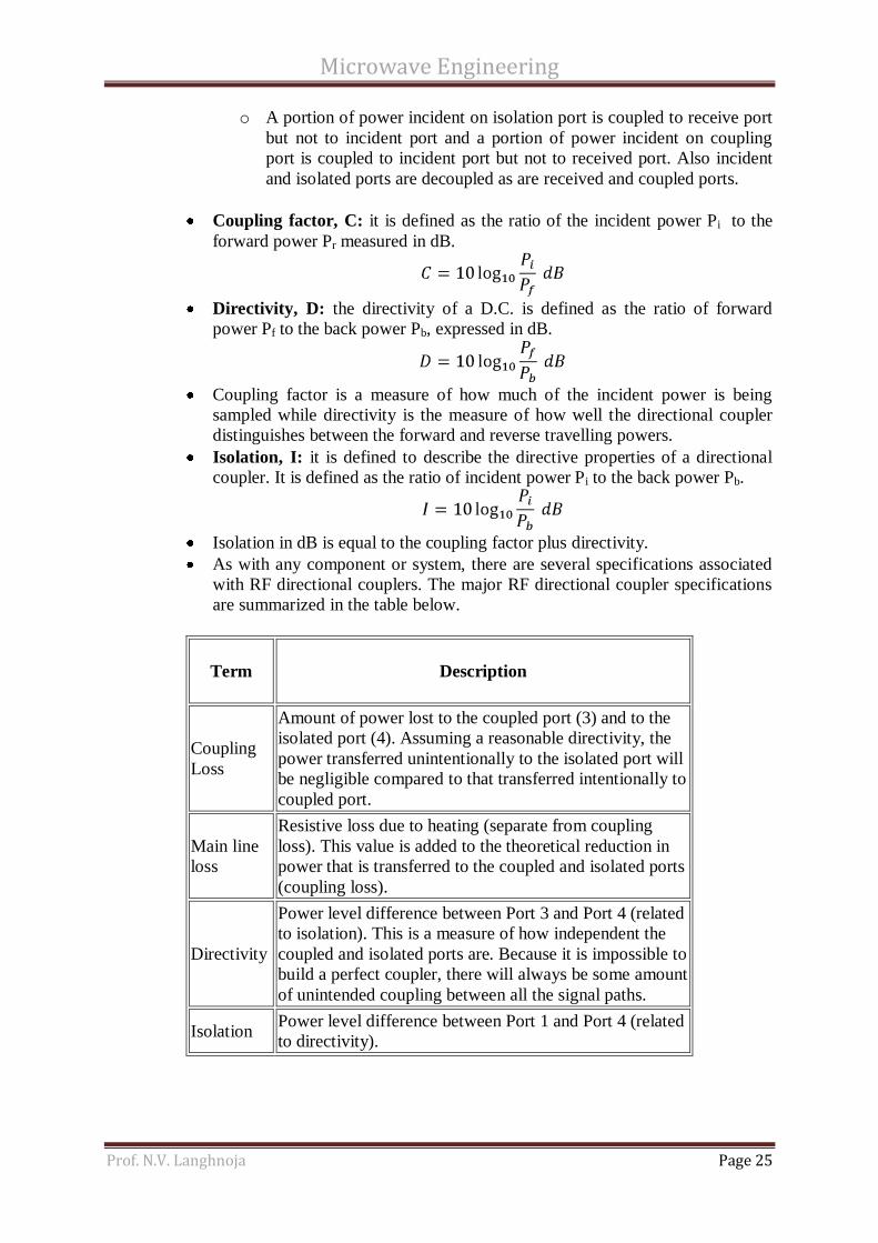
As with any component or system, there are several specifications associated
with RF directional couplers. The major RF directional coupler specifications
are summarized in the table below.
Term
Description
Coupling
Loss
Amount of power lost to the coupled port (3) and to the
isolated port (4). Assuming a reasonable directivity, the
power transferred unintentionally to the isolated port will
be negligible compared to that transferred intentionally to
coupled port.
Main line
loss
Resistive loss due to heating (separate from coupling
loss). This value is added to the theoretical reduction in
power that is transferred to the coupled and isolated ports
(coupling loss).
Directivity
Power level difference between Port 3 and Port 4 (related
to isolation). This is a measure of how independent the
coupled and isolated ports are. Because it is impossible to
build a perfect coupler, there will always be some amount
of unintended coupling between all the signal paths.
Isolation Power level difference between Port 1 and Port 4 (related
to directivity).

Microwave Engineering
Prof. N.V. Langhnoja Page 26
SCATTERING MATRIX OF DIRECTIONAL COUPLER
1 Directional coupler is a 4-port network. Hence [S] is 4 x 4 matrix.
2 In a directional coupler all four port are perfectly matched to the junction. Hence the
diagonal elements are zero.
3 From symmetry property,
Ideally back power is zero (Pb=0) i.e. there is no coupling between port 1 and 2.
4 Also there is no coupling between port 2 and port 3.
Substituting the above values of scattering parameters into S-matrix, we get,
5 From unitary property
Comparing equations 61, and 62, and 62 and 63, we get
Let assume that, is real and positive = ‘P’

Microwave Engineering
Prof. N.V. Langhnoja Page 27
Hence S-matrix of a directional coupler is reduced to