
212°F FEEDWATER SYSTEMS - Roth Pump Feedwater System D204...All Roth feedwater systems are designed...
4
BULLETIN D204-1R6 212°F FEEDWATER SYSTEMS ROTH PUMP COMPANY TOLL FREE 1-888-444-ROTH www.rothpump.com 100 to 800 boiler horsepower. 20 to 200 PSIG operating pressure. Up to 212˚F. Required NPSH - 1 ft. Full rated capacity of boiling feedwater in installations developing occasional flash returns. Roth patented pump guaranteed to deliver full rated capacity of boiling water at one foot NPSH. Full ball bearing design. No internal water lubricated bearings. Low silhouette assembly requires minimum head room. Patented drain-vent protects against back siphonage and steaming.
Transcript of 212°F FEEDWATER SYSTEMS - Roth Pump Feedwater System D204...All Roth feedwater systems are designed...

BULLETIN D204-1R6
212°F FEEDWATER SYSTEMS
ROTH PUMP COMPANY TOLL FREE 1-888-444-ROTHwww.rothpump.com
100 to 800 boiler horsepower.20 to 200 PSIG operating pressure.Up to 212˚F.Required NPSH - 1 ft.Full rated capacity of boiling feedwater in installations developing occasional flash returns.Roth patented pump guaranteed to deliver full rated capacity of boiling water at one foot NPSH.Full ball bearing design. No internal water lubricated bearings.Low silhouette assembly requires minimum head room.Patented drain-vent protects against back siphonage and steaming.

At low water level the electrical controller on the water column of the boiler starts the pump (A).
The pump begins filling the boiler and lowers the condensate level in the receiver.
The float switch (B) in the receiver opens the electric solenoid (C) valve on the fresh water line and begins to fill the receiver. The fresh water lowers the temperature of the condensate and activates the thermostat (D) which opens the regulator (E) by
means of a capillary tube connection.
Steam enters the perforated tube heater and is distributed evenly throughout the condensate and make-up water raising the temperature of the combined water storage.
When the boiler is satisfied the electrical controller stops the pump at high water level. The electric valve continues filling the receiver with fresh water until the float switch reaches high water shut-off. The steam
valve continues heating the stored water until the temperature reaches the preset point on the calibrated dial of the regulator at which point the thermostat shuts the regulator.
The atmospheric vent (H) exhausts any uncondensed steam to atmosphere. In the event the atmospheric vent is closed through error or accident the drain-vent (J) provides pressure relief.
SELECTION OF SYSTEMThe prevailing concern today of engineers selecting equipment for boiler feed is the Net Positive Suction Head characteristic of the pumps. This concern indicates an alertness to developments in the pump manufacturing industry, and an awareness of the causes of success and failure of pumps in handling feedwater at or close to boiling point.
ROTH PIONEERINGThe Roth Pump Co. has been an early pioneer in the industry in developing NPSH data on its products for use by engineers. It was the first manufacturer of regenerative turbine pumps to publish NPSH data on individual models. The Roth Pump Co. developed and published the first NPSH curves on regenerative turbine pumps in a format now used throughout the industry. It is the only manufacturer of regenerative turbine pumps today with numerous patents designed to improve the NPSH characteristics of its pumps.
ROTH ONE FOOT NPSH PUMPSThe Roth Pump Co. is the only pump manufacturer in the world today that offers a line of pumps with full performance at one foot NPSH at speeds of both 1750 and 3500 RPM in a range of differential heads up to 600 feet TDH and capacities up to 190 GPM.
ROTH 212˚F SYSTEMSAll Roth 212˚F feedwater systems are equipped with Roth one foot NPSH pumps guaranteed to deliver full rated capacity of boiling water to the boiler.
Roth one foot NPSH pumps were originally developed to pump 230˚F deaerated water from the deaerator to the boiler. This original design has now been improved to include high capacity models fully functional at one foot NPSH. Pumps utilized for these systems are equipped with mechanical seals suitable for 212˚F water. All Roth one foot NPSH deaerator pumps are full ball bearing mounted without internal water lubricated bearings.
PREHEATING ACCESSORIESRoth 212˚F feedwater systems are a low silhouette line of units available with or without automatic preheating accessories. Preheating
equipment when supplied consists of a pressure reducing valve, a mechanical temperature regulating valve controlled by a remote vapor tension thermostat and one or more perforated tube heaters.
ROTH PATENTED DRAIN-VENTAll systems are equipped with Roth patented drain-vent with tell-tale device for detecting internal steaming. The drain-vent is supplied with a connection for emergency overflow relief in the event of steaming in excess of the normal atmospheric vent capacity. Separate connections are supplied in the vessel to be used for atmospheric venting and overflow under normal conditions.
SANITARY MAKE-UP PROTECTIONMake-up water is introduced through the drain vent at the top of the vessel. An air gap serves as a vacuum breaker assuring against back siphonage hazards. A non-slam solenoid valve controlled by a float switch in the receiver opens when additional feedwater above normal return is required.
OPERATIONAll Roth feedwater systems are designed for pump control by the electrical boiler controller mounted on the boiler water column. The water level in the boiler closes the float operated switch at low boiler water level starting the pump motor. When the pump has provided sufficient feedwater to the boiler the switch opens stopping the pump motor.
DUPLEX SYSTEMSDuplex feedwater systems can be provided with alternate or standby pump. Duplex systems will be equipped with manual alternator unless otherwise specified.
MAGNETIC STARTERSAll three phase pump motors and all single phase pump motors of ¾ HP or larger must be started with line voltage magnetic starters. The control current from the boiler controller then actuates the magnetic holding coil in the starter. All starters are equipped with hand-off-automatic control to cut each pump in and out separately as desired.
Magnetic starters are mounted on the feed system at an accessible location between waist and shoulder height. They are spaced sufficiently far from the vessel to permit insulation of the vessel when desired.
PANEL MOUNTINGDuplex systems include two magnetic starters and a manual alternation switch mounted in a common panel enclosure with manual controls mounted through the cover. Wiring from starters to pumps is included unless otherwise specified.
DUAL SYSTEMSDual systems for twin ‘boiler installations are also available. Consult the factory for systems suitable for boiler banks with or without standby protection.
SAMPLE SPECIFICATIONSFurnish and install as shown on the drawings Roth (duplex-simplex) 212˚F feedwater system.
Unit shall be Roth Model __________ suitable for ______H.P. boiler operating at ______ PSI when pumping 212˚F feedwater.
Units shall be furnished as a complete package and shall include the following components:
1. Two (one for simplex) Roth one foot NPSH pumps certified by the manufacturer to deliver ____ GPM at _____ PSI without capacity loss when pumping 212˚F feedwater with 1ft. NPSH.
Pumps shall be Roth one foot NPSH design or equal, shall be of standard fitted construction and shall be equipped with mechanical shaft seal suitable for operation in 212°F feedwater.
Pumps shall be so constructed that the shaft and impeller are entirely supported by two grease lubricated sealed ball bearings.
Pumps shall be guaranteed by manufacturer for one year against defects in material and workmanship.
2. One horizontal receiver of _____gallon
Drg. No. B4991

20 PSI OPERATING PRESSURE
BoilerHP
Evap.Rate#/Hr
Evap.RateGPM
Min.PumpGPM
UnitNumber
Min.NPSHFeet
MotorHP RPM Pump
Disch.Rec.Cap.
100 3450 6.9 10.4 XE10020 1 1/2 1750 1 1/4 60
125 4312 8.6 13.0 XF12520 1 1/2 1750 1 1/4 100
150 5175 10.3 15.5 XF15020 1 3/4 1750 1 1/4 100
200 6900 13.8 20.7 XG20020 1 3/4 1750 1 1/4 180
250 8625 17.3 26.0 XG25020 1 1 1750 1 1/4 180
300 10350 20.7 31.0 XH30020 1 1 1750 1 1/4 250
350 12075 24.2 36.3 XH35020 1 1 1/2 1750 1 1/4 250
400 13800 27.6 41.5 XJ50020 1 3 1750 2 350
500 17250 34.5 51.5 XJ50020 1 3 1750 2 350
600 20700 42.0 63.0 XK60020 1 3 1750 2 500
700 24150 48.3 72.5 XK70020 1 3 1750 2 500
800 27600 55.2 83.0 XL80020 1 3 1750 2 750
50 PSI OPERATING PRESSURE100 3450 6.9 10.4 XE10050 1 1 1750 1 1/4 60
125 4312 8.6 13.0 XF12550 1 1 1750 1 1/4 100
150 5175 10.3 15.5 XF15050 1 1 1/2 1750 1 1/4 100
200 6900 13.8 20.7 XG20050 1 2 1750 1 1/4 180
250 8625 17.3 26.0 XG25050 1 3 1750 1 1/4 180
300 10350 20.7 31.0 XH30050 1 3 1750 1 1/4 250
350 12075 24.2 36.3 XH35050 1 5 1750 1 1/4 250
400 13800 27.6 41.5 XJ40050 1 5 1750 2 350
500 17250 34.5 51.5 XJ50050 1 5 1750 2 350
600 20700 42.0 63.0 XK70050 1 5 1750 2 500
700 24150 48.3 72.5 XK70050 1 5 1750 2 500
800 27600 55.2 83.0 XL80050 1 10 1750 2 750
75 PSI OPERATING PRESSURE100 3450 6.9 10.4 XE10075 1 2 3500 1 1/4 60
125 4312 8.6 13.0 XF12575 1 2 3500 1 1/4 100
150 5175 10.3 15.5 XF15100 1 3 3500 1 1/4 100
200 6900 13.8 20.7 XG20150 1 5 3500 1 1/4 180
250 8625 17.3 26.0 XG20150 1 5 3500 1 1/4 180
300 10350 20.7 31.0 XH35100 1 5 3500 1 1/4 250
350 12075 24.2 36.3 XH35100 1 5 3500 1 1/4 250
400 13800 27.6 41.5 XJ40075 1 5 3500 1 1/4 350
500 17250 34.5 51.5 XJ50075 1 7 1/2 3500 1 1/4 350
600 20700 42.0 63.0 XK60100 1 10 3500 2 500
700 24150 48.3 72.5 XK70125 1 20 3500 2 500
800 27600 55.2 83.0 XL80125 1 20 3500 2 750
100 PSI OPERATING PRESSURE100 3450 6.9 10.4 XE10100 1 2 3500 1 1/4 60
125 4312 8.6 13.0 XF12100 1 2 3500 1 1/4 100
150 5175 10.3 15.5 XF15100 1 3 3500 1 1/4 100
200 6900 13.8 20.7 XG20150 1 5 3500 1 1/4 180
100 PSI OPERATING PRESSURE (cont.)
BoilerHP
Evap.Rate#/Hr
Evap.RateGPM
Min.PumpGPM
UnitNumber
Min.NPSHFeet
MotorHP RPM Pump
Disch.Rec.Cap.
250 8625 17.3 26.0 XG20150 1 5 3500 1 1/4 180
300 10350 20.7 31.0 XH35100 1 5 3500 1 1/4 250
350 12075 24.2 36.3 XH35100 1 5 3500 1 1/4 250
400 13800 27.6 41.5 XJ40100 1 7 1/2 3500 1 1/4 350
500 17250 34.5 51.5 XJ50100 1 10 3500 2 350
600 20700 42.0 63.0 XK60100 1 10 3500 2 500
700 24150 48.3 72.5 XK70125 1 20 3500 2 500
800 27600 55.2 83.0 XL80125 1 20 3500 2 750
125 PSI OPERATING PRESSURE100 3450 6.9 10.4 XE10125 1 3 3500 1 1/4 60
125 4312 8.6 13.0 XF12150 1 5 3500 1 1/4 100
150 5175 10.3 15.5 XF12150 1 5 3500 1 1/4 100
200 6900 13.8 20.7 XG20150 1 5 3500 1 1/4 180
250 8625 17.3 26.0 XG25125 1 7 1/2 3500 1 1/4 180
300 10350 20.7 31.0 XH30125 1 7 1/2 3500 1 1/4 250
350 12075 24.2 36.3 XH35150 1 10 3500 2 250
400 13800 27.6 41.5 XJ40150 1 10 3500 2 350
500 17250 34.5 51.5 XJ50150 1 15 3500 2 350
600 20700 42.0 63.0 XK60150 1 15 3500 2 500
700 24150 48.3 72.5 XK70125 1 20 3500 2 500
800 27600 55.2 83.0 XL801256 1 20 3500 2 750
150 PSI OPERATING PRESSURE100 3450 6.9 10.4 XE10150 1 5 3500 1 1/4 60
125 4312 8.6 13.0 XF12150 1 5 3500 1 1/4 100
150 5175 10.3 15.5 XF15150 1 5 3500 1 1/4 100
200 6900 13.8 20.7 XG20150 1 5 3500 1 1/4 180
250 8625 17.3 26.0 XG25150 1 7 1/2 3500 1 1/4 180
300 10350 20.7 31.0 XH35150 1 10 3500 2 250
350 12075 24.2 36.3 XH35150 1 10 3500 2 250
400 13800 27.6 41.5 XJ40150 1 10 3500 2 350
500 17250 34.5 51.5 XJ50150 1 15 3500 2 350
600 20700 42.0 63.0 XK60150 1 15 3500 2 500
200 PSI OPERATING PRESSURE100 3450 6.9 10.4 XE10200 1 7 1/2 3500 1 1/4 60
125 4312 8.6 13.0 XF12200 1 7 1/2 3500 1 1/4 100
150 5175 10.3 15.5 XF15200 1 10 3500 1 1/4 100
200 6900 13.8 20.7 XG25200 1 10 3500 1 1/4 180
250 8625 17.3 26.0 XG25200 1 10 3500 1 1/4 180
300 10350 20.7 31.0 XH35200 1 15 3500 2 250
350 12075 24.2 36.3 XH35200 1 15 3500 2 250
400 13800 27.6 41.5 XJ50200 1 20 3500 2 350
500 17250 34.5 51.5 XJ50200 1 20 3500 2 350
212˚F SELECTION TABLES
capacity with steel channel bolt-on legs. Receiver shall be of 3/16” carbon steel construction with flat flanged heads and shall be fitted with openings for inlet, outlet, vent, overflow, gauge glass, thermometer and drain.
3. Furnish Roth drain-vent assembly to provide emergency overflow if boiler feedwater temperature exceeds 212˚F, and to provide a vacuum break to protect against back siphonage at make-up water connection.
4. Provide pressure gauges complete with siphon and cock mounted in the pump discharge.
5. Provide gauge glass, thermometer and magnesium anode mounted on the receiver.
6. Provide all piping between receiver outlet and pump suction complete with self-cleaning “L” type strainers with flanged blow-off outlet
and gate valves. Pipe, strainers, and valves must be sized for less than 3 feet per second velocity liquid flow at maximum pump capacity at specified operating head.
7. Provide fresh water make-up by a non-slam solenoid valve mounted on the drain vent and controlled by a float switch mounted on receiver. Solenoid valve shall have a capacity at 30 PSI inlet pressure equal to the normal rated evaporation of the boiler. Control current shall be _____ phase ______volts.
8. (For preheat equipped units) Provide one self-operated pressure / temperature regulator selected to raise the temperature of the stored feedwater ____˚F with as much as _______GPM make up water required. Furnish complete with vapor tension thermostat. Regulator shall be connected to a perforated tube heater mounted in the receiver.
9. Two (one for simplex) (1750 , 3500RPM) drip proof motors of characteristics shown on schedule. Motors to be flexible coupled to pumps and mounted on common base plate. Motors shall not be loaded beyond a service factor of 1.0 for the motor nameplate horsepower rating when operating at specified discharge pressure or below.
10. Provide two (one for simplex ) three pole, three phase across the line magnetic starters with (3) overload heaters, hand-off-automatic (HOA) selector switch panel mounted in a single NEMA I enclosure and wired to the motors.
11. All of the above to be furnished as a complete package unit, factory assembled, piped, and wired and ready for connection to services at thebuilding.
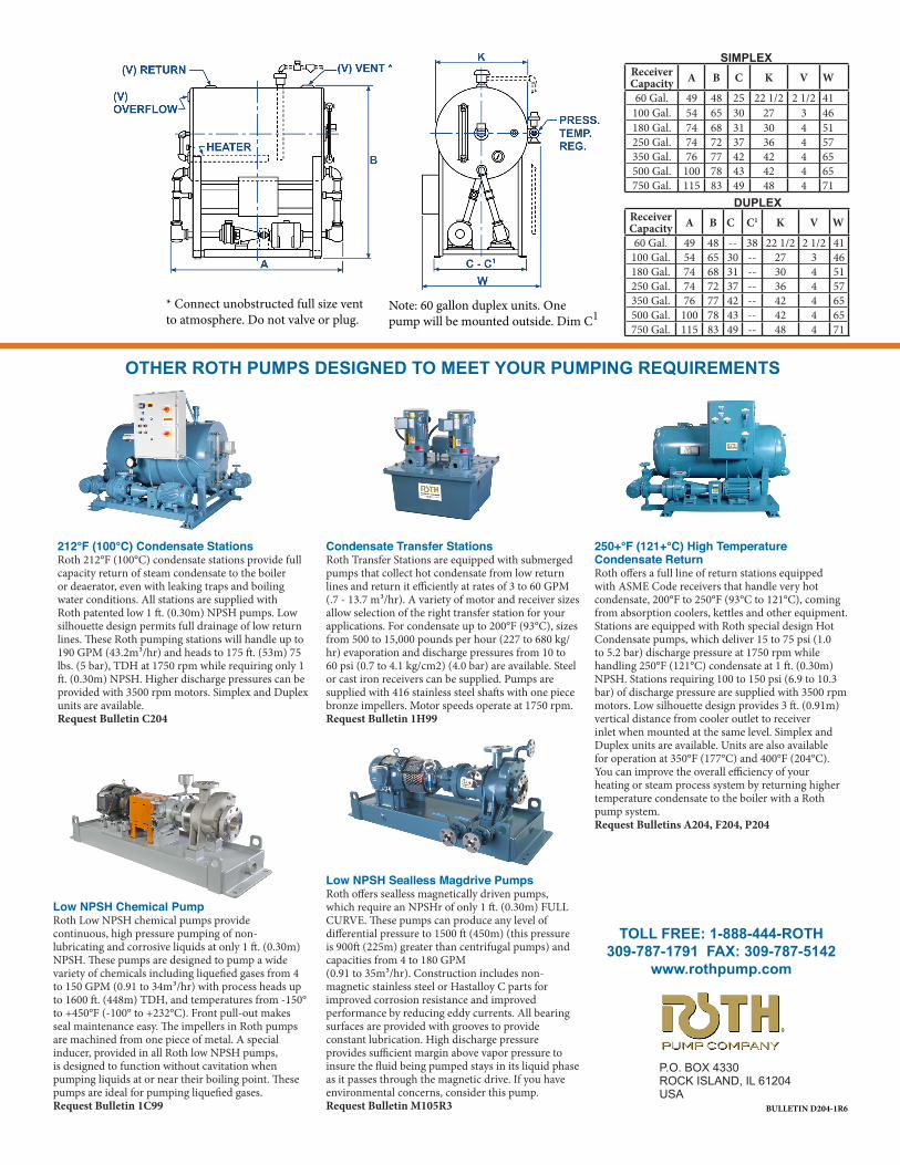
DUPLEXReceiver Capacity A B C C1 K V W
60 Gal. 49 48 -- 38 22 1/2 2 1/2 41100 Gal. 54 65 30 -- 27 3 46180 Gal. 74 68 31 -- 30 4 51250 Gal. 74 72 37 -- 36 4 57350 Gal. 76 77 42 -- 42 4 65500 Gal. 100 78 43 -- 42 4 65750 Gal. 115 83 49 -- 48 4 71
SIMPLEXReceiver Capacity A B C K V W
60 Gal. 49 48 25 22 1/2 2 1/2 41100 Gal. 54 65 30 27 3 46180 Gal. 74 68 31 30 4 51250 Gal. 74 72 37 36 4 57350 Gal. 76 77 42 42 4 65500 Gal. 100 78 43 42 4 65750 Gal. 115 83 49 48 4 71
* Connect unobstructed full size vent to atmosphere. Do not valve or plug.
Note: 60 gallon duplex units. One pump will be mounted outside. Dim C1
OTHER ROTH PUMPS DESIGNED TO MEET YOUR PUMPING REQUIREMENTS
212°F (100°C) Condensate StationsRoth 212°F (100°C) condensate stations provide full capacity return of steam condensate to the boiler or deaerator, even with leaking traps and boiling water conditions. All stations are supplied with Roth patented low 1 ft. (0.30m) NPSH pumps. Low silhouette design permits full drainage of low return lines. These Roth pumping stations will handle up to 190 GPM (43.2m³/hr) and heads to 175 ft. (53m) 75 lbs. (5 bar), TDH at 1750 rpm while requiring only 1 ft. (0.30m) NPSH. Higher discharge pressures can be provided with 3500 rpm motors. Simplex and Duplex units are available.Request Bulletin C204
Condensate Transfer StationsRoth Transfer Stations are equipped with submerged pumps that collect hot condensate from low return lines and return it efficiently at rates of 3 to 60 GPM (.7 - 13.7 m³/hr). A variety of motor and receiver sizes allow selection of the right transfer station for your applications. For condensate up to 200°F (93°C), sizes from 500 to 15,000 pounds per hour (227 to 680 kg/hr) evaporation and discharge pressures from 10 to 60 psi (0.7 to 4.1 kg/cm2) (4.0 bar) are available. Steel or cast iron receivers can be supplied. Pumps are supplied with 416 stainless steel shafts with one piece bronze impellers. Motor speeds operate at 1750 rpm.Request Bulletin 1H99
250+°F (121+°C) High TemperatureCondensate ReturnRoth offers a full line of return stations equipped with ASME Code receivers that handle very hot condensate, 200°F to 250°F (93°C to 121°C), coming from absorption coolers, kettles and other equipment. Stations are equipped with Roth special design Hot Condensate pumps, which deliver 15 to 75 psi (1.0 to 5.2 bar) discharge pressure at 1750 rpm while handling 250°F (121°C) condensate at 1 ft. (0.30m) NPSH. Stations requiring 100 to 150 psi (6.9 to 10.3 bar) of discharge pressure are supplied with 3500 rpm motors. Low silhouette design provides 3 ft. (0.91m) vertical distance from cooler outlet to receiver inlet when mounted at the same level. Simplex and Duplex units are available. Units are also available for operation at 350°F (177°C) and 400°F (204°C). You can improve the overall efficiency of your heating or steam process system by returning higher temperature condensate to the boiler with a Roth pump system.Request Bulletins A204, F204, P204
Low NPSH Chemical PumpRoth Low NPSH chemical pumps provide continuous, high pressure pumping of non-lubricating and corrosive liquids at only 1 ft. (0.30m) NPSH. These pumps are designed to pump a wide variety of chemicals including liquefied gases from 4 to 150 GPM (0.91 to 34m³/hr) with process heads up to 1600 ft. (448m) TDH, and temperatures from -150° to +450°F (-100° to +232°C). Front pull-out makes seal maintenance easy. The impellers in Roth pumps are machined from one piece of metal. A special inducer, provided in all Roth low NPSH pumps, is designed to function without cavitation when pumping liquids at or near their boiling point. These pumps are ideal for pumping liquefied gases.Request Bulletin 1C99
Low NPSH Sealless Magdrive PumpsRoth offers sealless magnetically driven pumps, which require an NPSHr of only 1 ft. (0.30m) FULL CURVE. These pumps can produce any level of differential pressure to 1500 ft (450m) (this pressure is 900ft (225m) greater than centrifugal pumps) and capacities from 4 to 180 GPM (0.91 to 35m³/hr). Construction includes non-magnetic stainless steel or Hastalloy C parts for improved corrosion resistance and improved performance by reducing eddy currents. All bearing surfaces are provided with grooves to provide constant lubrication. High discharge pressure provides sufficient margin above vapor pressure to insure the fluid being pumped stays in its liquid phase as it passes through the magnetic drive. If you have environmental concerns, consider this pump.Request Bulletin M105R3
TOLL FREE: 1-888-444-ROTH309-787-1791 FAX: 309-787-5142
www.rothpump.com
P.O. BOX 4330ROCK ISLAND, IL 61204 USA
BULLETIN D204-1R6


