211 BLUECOAT-510 Install Guide 4.x 5.x
110
Blue Coat ® Systems SG510 Series Installation Guide Version: SGOS 4.2.x and 5.1.x
-
Upload
awadhesh06 -
Category
Documents
-
view
89 -
download
2
Transcript of 211 BLUECOAT-510 Install Guide 4.x 5.x

Blue Coat® SystemsSG510 Series
Installation Guide
Version: SGOS 4.2.x and 5.1.x

P/N 231-02833 Blue Coat SG510 Installation Guide page ii
Contact InformationBlue Coat Systems Inc.420 North Mary Ave Sunnyvale, CA 94085-4121
http://www.bluecoat.com/support/index.html
http://www.bluecoat.com
For concerns or feedback about the documentation: [email protected]
Copyright© 1999-2007 Blue Coat Systems, Inc. All rights reserved worldwide. No part of this document may be reproduced by any means nor modified, decompiled, disassembled, published or distributed, in whole or in part, or translated to any electronic medium or other means without the written consent of Blue Coat Systems, Inc. All right, title and interest in and to the Software and documentation are and shall remain the exclusive property of Blue Coat Systems, Inc. and its licensors. ProxySG™, ProxyAV™, CacheOS™, SGOS™, Spyware Interceptor™, Scope™, RA Connector™, RA Manager™, Remote Access™ are trademarks of Blue Coat Systems, Inc. and CacheFlow®, Blue Coat®, Accelerating The Internet®, WinProxy®, AccessNow®, Ositis®, Powering Internet Management®, The Ultimate Internet Sharing Solution®, Permeo®, Permeo Technologies, Inc.®, and the Permeo logo are registered trademarks of Blue Coat Systems, Inc. All other trademarks contained in this document and in the Software are the property of their respective owners.
BLUE COAT SYSTEMS, INC. DISCLAIMS ALL WARRANTIES, CONDITIONS OR OTHER TERMS, EXPRESS OR IMPLIED, STATUTORY OR OTHERWISE, ON SOFTWARE AND DOCUMENTATION FURNISHED HEREUNDER INCLUDING WITHOUT LIMITATION THE WARRANTIES OF DESIGN, MERCHANTABILITY OR FITNESS FOR A PARTICULAR PURPOSE AND NONINFRINGEMENT. IN NO EVENT SHALL BLUE COAT SYSTEMS, INC., ITS SUPPLIERS OR ITS LICENSORS BE LIABLE FOR ANY DAMAGES, WHETHER ARISING IN TORT, CONTRACT OR ANY OTHER LEGAL THEORY EVEN IF BLUE COAT SYSTEMS, INC. HAS BEEN ADVISED OF THE POSSIBILITY OF SUCH DAMAGES.
Document Number: 231-02833
Document Revision: A.0 July 2006
Contents
Chapter 1: Unpack and Rack a Blue Coat SG510
Unpacking a SG510................................................................................................... 8
SG510 Front Panel Features..................................................................................... 8
SG510 Back Panel Features ...................................................................................... 9
Mounting the SG510 in an Equipment Rack....................................................... 10Rack-Mounting Notes ......................................................................................... 10
Attaching the Cable Management Support......................................................... 11
Installing the Disk Drives ...................................................................................... 12
Connecting the Cables............................................................................................ 16
Powering On the SG510 ......................................................................................... 16Power LED ............................................................................................................ 16
Chapter 2: Configure a SG510
Overview of First-Time Configuration ................................................................ 19
Section A: Configuring the SG510 with the Front Panel Features
LCD Behavior .......................................................................................................... 21
System LCD and Modes......................................................................................... 22
SG510 Control Buttons ........................................................................................... 24
Using the Front Panel to Configure Basic Network Settings............................ 25
Section B: Placing the SG510 into the Network
Section C: Initial Configuration with a Web Browser
Requirements........................................................................................................... 29
Where to go next ..................................................................................................... 30
Section D: Initial Configuration Using a Direct Serial Port Connection
Section E: Configuring the SG510 from a Remote Location
P/N 231-02833 Blue Coat SG510 Installation Guide page iii

Step One—Enter the Remote Configuration Parameters Using a Web Browser............................................................................ 55
Step Two—Complete the Configuration .......................................................... 59
Section F: Logging on to the SG510
Logging on to the SG510 Management Console ............................................. 62Logging on to the SG510 CLI ............................................................................. 64
Section G: Configuring a Front-Panel PIN
Section H: Configuring the Front-Panel LCD Behavior
Chapter 3: Removing and Installing Disk Drives
Removing a Disk Drive .......................................................................................... 72
Installing a New Disk Drive .................................................................................. 73
Chapter 4: Option Cards
Dual Gigabit Ethernet 1000B-SX (optical) Card............................................... 75Dual Gigabit Ethernet (copper) Pass-Through Card ...................................... 75SSL Accelerator Card........................................................................................... 75
Chapter 5: Troubleshooting
The SG510 does not power up .............................................................................. 77
The Initial Configuration Page is Not Accessible............................................... 78
Creating A Static Route to the SG510................................................................... 79
You cannot access the serial console .................................................................... 79
You cannot access the Management Console ..................................................... 79
A Security Warning Appears for the Initial Configuration Web Page ........... 80
The SG510 certificate is no longer valid .............................................................. 80
Resetting the SG510 to Factory Defaults.............................................................. 81
The SG510 Does Not Come Back Up After Rebooting ...................................... 83
Appendix A: Specifications
General Specifications ............................................................................................ 85
P/N 231-02833 Blue Coat SG510 Installation Guide page iv

Environmental Specifications................................................................................ 86
Appendix B: Regulatory Statements
General System Cautions....................................................................................... 87
Power Cord Cautions ............................................................................................. 87
Class A Digital Warning ........................................................................................ 88
Advertencia Digital Clase A.................................................................................. 88
EC Community EMC Warning ............................................................................. 88
Advertencia EMC de la Comunidad EC ............................................................. 88
Canadian EC EMC Warning ................................................................................. 88
Australia/New Zealand EC EMC Warning........................................................ 89
Taiwan BSMI Notification ..................................................................................... 89
Japan VCCI EMC Notification .............................................................................. 89
Battery Warning Notification................................................................................ 89
Chinese Battery Warning Notification................................................................. 90
China CCC Notification ......................................................................................... 90
Lasers ........................................................................................................................ 90
Declaration of Conformity..................................................................................... 94
Appendix C: Apéndice C: Declaraciones Regulatorias
Precauciones generales del sistema...................................................................... 95
Conexión del cable de alimentación..................................................................... 95
Lasers ........................................................................................................................ 96
Appendix D: Anhang D: Regulierende Anweisungen
Allgemeine Systemvorsichtsmassnahmen.......................................................... 97
Anschliessen des Stromkabels .............................................................................. 97
Lasers ........................................................................................................................ 98
Appendix E: Simplified Chinese Regulatory Statements
P/N 231-02833 Blue Coat SG510 Installation Guide page v

Appendix F: Traditional Chinese Regulatory Statements
Index
P/N 231-02833 Blue Coat SG510 Installation Guide page vi

Chapter 1: Unpack and Rack a Blue Coat SG510
This installation guide provides general instructions for installing, configuring, and using the Blue Coat SG510.
This chapter explains how to unpack the SG510, install it in an equipment rack, insert the disk drives, connect the cables, and power it on.
After you have completed the first-time configuration of the SG510 and have logged in, you should do the following:
• Upgrade the SG510 software by downloading the latest patch release (available at http://download.bluecoat.com).
• Fully configure the appliance.
To configure the SG510, you will need to download the Blue Coat ProxySG Configuration and Management Guide Suite, (the CMG) available on the Blue Coat Web site at www.bluecoat.com. (Look for WebPower Login under Support.)
You can also find tech briefs (technical briefs) on the Blue Coat Web site.
If you log on to the SG510 using a Web browser, you can access the online help by clicking the Help button on the Management Console screens. The Management Console is the graphical user interface for the SG510.
See “Logging on to the SG510” on page 62 for more information.
Important: Follow all warnings and instructions marked on the product and included in this manual.
P/N 231-02833 Blue Coat SG510 Installation Guide page 7

Unpacking a SG510When you receive and unpack the SG510, verify that the package contains the following items:
SG510 Front Panel FeaturesThe figure below shows the front of a SG510.
Figure 1-1: The Front of a SG510
The SG510 front panel has the following features:
• An LCD and six control buttons to monitor activity and configure basic networking settings.
• Power, Disk Drive, and LAN LEDs.
• A front panel that pivots downward and pulls outward giving you access to up to two disk drives.
• Mounting brackets that extend from each end of the chassis to secure a SG510 to an equipment rack.
• Blue Coat SG510 Series Appliance • AC Power cord• Quick Start Guide • Disk drives (up to two)• Null-modem serial cable • Cable Management Support• License, Warranty, and Safety
information
Power, Disk Drive, and LAN LEDs
Control buttons
LCDPlates that attach to the front of the equipment rack
Front panel
P/N 231-02833 Blue Coat SG510 Installation Guide page 8

You can mount a SG510 in a standard mounting rack. See “Mounting the SG510 in an Equipment Rack” on page 10 for rack mounting instructions.
SG510 Back Panel FeaturesThe figure below shows the back of a SG510.
Figure 1-2: The Back of a SG510
The following features are located on the back of the SG510:
• An AC power connector.
• Two USB (Universal Serial Bus) ports.
• A serial port to connect to a PC, to a serial terminal, or to a stand-alone serial console terminal.
• Two full-duplex, auto-sensing Ethernet network adapter ports supporting 10/100/1000 Base-T connections.
• An expansion slot for optional network, bridging, or SSL cards. See Chapter 4: ’Option Cards" for more information about SG510 option cards.
AC Power Connector
Ethernet Adapter
Ports
Serial Port
USBPorts
Expansion Slot for SSL or Bridge Card
P/N 231-02833 Blue Coat SG510 Installation Guide page 9

Mounting the SG510 in an Equipment RackThe Blue Coat SG510 is designed to fit into a standard telco-style or four-post cabinet style equipment rack.
The SG510 ships with the rack-mounting ears installed.
Rack-Mounting Notes
Read these notes before rack-mounting the SG510.
• Elevated Operating Temperature—If installed in a closed or multi-unit rack assembly, the operating ambient temperature of the rack environment may be greater than the ambient room temperature. Therefore, consideration should be given to installing the equipment in an environment compatible with the maximum ambient temperature specified by the manufacturer.
• Reduced Air Flow—Installation of the equipment in a rack should be such that the amount of air flow required for safe operation of the equipment is not compromised.
• Mechanical Loading—Mounting of the equipment in the rack should be such that a hazardous condition is not achieved due to uneven mechanical loading.
• Circuit Overloading—Consideration should be given to the connection of the equipment to the supply circuit and the effect that overloading of the circuits might have on overcurrent protection and supply wiring. Appropriate consideration of equipment nameplate ratings should be used when addressing this concern.
• Earthing (Grounding)—Reliable earthing of rack-mounted equipment should be maintained. Particular attention should be given to supply connections other than direct connections to the branch circuit (for example, use of power strips).
Attach the SG510 to the equipment mounting rack:
1 Position the SG510 into the equipment rack so that the ears of the brackets align with the holes in the front of the rack.
2 Use equipment-rack screws to mount the SG510 to the equipment rack.
Figure 1-3 shows a SG510 flush-mounted on a Telco equipment rack.
P/N 231-02833 Blue Coat SG510 Installation Guide page 10

Figure 1-3: SG510 Attached to a Telco Equipment Rack
Attaching the Cable Management SupportThe cable management support routes network serial cables to avoid tangling.
Fasten the cable management support to the back of the system as follows:
1 Position the cable management support at the back of the system on the right; secure it with a 6-32 x 1/4 flathead screw at the side.
Figure 1-4: Attach the Cable Management Support
When you attach cables to the system, run them through this clip to keep them from tangling.
Use equipment-rack screws
to attach to the SG510 to the
rack
Attach the cable management support with a flathead screw
P/N 231-02833 Blue Coat SG510 Installation Guide page 11

Installing the Disk DrivesThe following instructions are for a first-time installation of the disk drives that are shipped with the SG510. The drive slots on each end of the appliance contain non-removable, blank disk-drive spacers.
Figure 1-5: Disk-Drive Slot Arrangement
Important: You cannot hot-swap disks in the SG510; you will lose all configuration settings.
Drive slot 2Non-removable spacer Drive slot 1
Non-removable spacer
P/N 231-02833 Blue Coat SG510 Installation Guide page 12

Important: The SG510 ships with two disk-drive spacers already installed in the drive slots at each end of the system. Do not attempt to remove these blank drive spacers. If you ordered only a single disk drive, the unit ships with a third disk-drive spacer installed in Slot 2.
1 Press the push tabs on each side of the front-panel bezel to release the locked position of the front panel. Pull the front panel forward and down.
Figure 1-6: Access the Disk Drive Slots
Press the push tabs on each side of the front-panel bezel
The front panel swings forward and down
P/N 231-02833 Blue Coat SG510 Installation Guide page 13

If other equipment blocks the front panel from opening all the way, you can pull the front panel forward, sliding out the front-panel tray until you can access the disk drives.
Figure 1-7: Access the Disk Drive Slots
2 Position the disk-drive carrier upright, so that the disk-drive button appears on the right; press this button to release the disk-drive lever.
Figure 1-8: Release the Disk-Drive Lever
3 Use the lever to slide the disk-drive carrier into the first open slot (Slot 1, second from left).
Important: Always insert disk drives from left to right. If you have only one disk drive, install it into drive Slot 1.
Pull out the front-panel tray, if necessary, to access the disk drives
Press the disk-drive button
The disk-drive lever is released
P/N 231-02833 Blue Coat SG510 Installation Guide page 14

Figure 1-9: Insert the Disk-Drive Carrier
4 When the disk-drive carrier meets the SG510 frame, gently push the lever in towards the button until the handle latches on the button.
5 Repeat steps 2 to 4 to install the optional disk drive in drive slot 2.
Note: If you need to remove a drive, press the button on the right side of the disk-drive carrier to release the lever. Pull the lever towards you to slide the carrier out of the slot.
Drive Slot 1
P/N 231-02833 Blue Coat SG510 Installation Guide page 15

Connecting the CablesConnect the network cables, serial cable, and AC power cord.
Figure 1-10: Connect the Cables to the Back of the System
1 Plug the network cable into adapter 0. Plug a second cable into the other adapter if desired.
The two full-duplex, auto-sensing Ethernet network adapters supporting 10/100/1000 Base-T connections are labeled 0 and 1.
2 Plug the serial cable into the serial connector, if necessary.
If you attach the serial cable, you can connect the system to a PC, serial terminal, or stand-alone Serial Console box.
3 Plug the enclosed power cord into the power cord receptacle.
Powering On the SG5101 After you have connected the power cord to the rear of the system, plug the
other end of the power cord into a power receptacle.
2 Verify that the system has powered on successfully. See the four system states described below and the corresponding states of the Power LED.
Power LED
• No color: the SG510 is powered off or non-functional
Ethernet adapter ports (Ports 0 and 1)
Serial portAC Power
P/N 231-02833 Blue Coat SG510 Installation Guide page 16

• Solid Amber: the SG510 is powered on but unable to perform tasks (for example, while booting up)
• Flashing Green to Amber: the SG510 is powered on but is not configured
• Green: the SG510 is powered on and at least minimally configured
3 The three steps below show a typical, first-time, start-up sequence.
• The Power LED lights up and the LCD becomes green and displays the name Blue Coat.
• The Power LED starts of solid amber and then begins flashing green and amber.
• After a moment, the disk drive LEDs corresponding to the disk drives that are installed light up.
• If you are connected to the network, the LAN LEDs light up.
• The LCD displays IP address not configured (if a first-time configuration has not been done) or it cycles between CPU utilization and the hostname.
Figure 1-11: Verify Successful Power On
The SG510 comes with all software installed. To configure a SG510 for the first time go to “Configure a SG510” on page 19.
Power LED Disk Drive
LEDs (2)LCD LAN status LEDs (2)
P/N 231-02833 Blue Coat SG510 Installation Guide page 17

P/N 231-02833 Blue Coat SG510 Installation Guide page 18

Chapter 2: Configure a SG510
You need to configure a SG510 the first time you power it on to set the basic network parameters and to make sure that the SG510 hardware and software are working properly.
Overview of First-Time ConfigurationThere are four ways to configure a SG510 the first time you power it on. Each of these methods of configuring a SG510 let you make the basic network settings required to test the connection and functionality.
Configuration Method
Description
Front Panel Use the front-panel LCD and buttons. (This is the quickest and easiest way to do a first-time configuration.
To use the front panel method, go to “Configuring the SG510 with the Front Panel Features” on page 21.
Serial Console Use a direct connection between the system and a PC, or a serial terminal, or a stand-alone serial console terminal.
To use the serial console connection, go to “Initial Configuration Using a Direct Serial Port Connection” on page 38.
Web Browser Use a Web browser. To use this method for SGOS 5.1.1.x and later, you must first configure the IP address of the SG510 using the serial console or front panel. Blue Coat recommends using the Web browser configuration method if you are running SGOS 5.1.1.x or later.
To use the Web browser configuration method, go to “Initial Configuration with a Web Browser” on page 29.
P/N 231-02833 Blue Coat SG510 Installation Guide page 19

After you complete the first-time configuration, you must log on to the system and use the command-line interface (CLI) or the Management Console graphical user interface to fully configure the system. First-time configuration is designed only to make sure that the SG510 hardware and software are working properly. See “Logging on to the SG510” on page 62 for more information.
Refer to the Blue Coat ProxySG Configuration and Management Guide Suite for information on how to fully configure the software. Download the Blue Coat ProxySG Configuration and Management Guide Suite, available on the Blue Coat Web site at www.bluecoat.com. (Look for WebPower Login under Support.)
Remote Configuration
You can use this method if your appliance is running SGOS 4.2.2.x or later. The remote configuration method is not supported for appliances running 5.1.1.x or later.
Use two people to remotely configure the appliance—one who enters the configuration parameters from a remote location and another who places the SG510 into the network and finalizes the configuration by clicking a generated URL.
To use the remote configuration method, go to “Configuring the SG510 from a Remote Location” on page 55.
Configuration Method
Description
P/N 231-02833 Blue Coat SG510 Installation Guide page 20

Section A: Configuring the SG510 with the Front Panel Features
You can configure a SG510 the first time you power it on using the front panel LCD and control buttons.
Figure 2-1: Front Panel LCD and Control Buttons
Use the LCD and the buttons to monitor the system and to set the basic networking parameters.
LCD BehaviorThe default behavior of the front-panel LCD is to turn off after 30 seconds. The front-panel LCD behavior is configurable; see “Configuring the Front-Panel LCD Behavior” on page 68 for information.
To Turn the Front-Panel LCD Back On:
• If the SG510 is powered on, but the front-panel LCD is off, press any front-panel control button (see Figure 2-1) to turn the LCD back on.
After the LCD illuminates, the front-panel control buttons return to their normal behavior.
Menu button
LCD
Enter button
Arrow buttons
P/N 231-02833 Blue Coat SG510 Installation Guide page 21

System LCD and ModesThe system has three modes.
Status Mode The default mode. Before the system is configured, the LCD in Status mode displays IP address not configured. After initial configuration, the LCD in Status mode displays CPU utilization and freshness statistics.
In Status mode, there is no cursor in the LCD.
Configuration Mode
From Status mode, push the Enter button to go to Configuration mode. In Configuration mode, you can use the Up and Down arrow buttons to cycle the LCD through the six networking parameters (IP Address, Subnet mask, Gateway address, DNS address, Console Password, and Enable Password).
In Configuration mode, the cursor is an underscore in the LCD.
P/N 231-02833 Blue Coat SG510 Installation Guide page 22
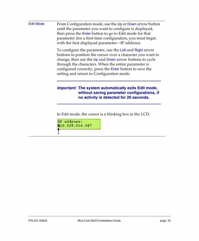
Edit Mode From Configuration mode, use the Up or Down arrow button until the parameter you want to configure is displayed, then press the Enter button to go to Edit mode for that parameter (for a first-time configuration, you must begin with the first displayed parameter—IP address).
To configure the parameter, use the Left and Right arrow buttons to position the cursor over a character you want to change, then use the Up and Down arrow buttons to cycle through the characters. When the entire parameter is configured correctly, press the Enter button to save the setting and return to Configuration mode.
Important: The system automatically exits Edit mode, without saving parameter configurations, if no activity is detected for 20 seconds.
In Edit mode, the cursor is a blinking box in the LCD.
P/N 231-02833 Blue Coat SG510 Installation Guide page 23

SG510 Control ButtonsUse the control buttons in conjunction with the modes as follows:
Enter Button The Enter button functions as follows:Status mode: When you push the Enter button in Status mode, the system enters Configuration mode. In Configuration mode, one of the six configurable parameters displays in the LCD (starting with IP address). Configuration mode: When you push the Enter button in Configuration mode, the system enters Edit mode for the parameter displayed.Edit mode: When you push the Enter button in Edit mode, the system saves any changes you made to the parameter displayed and returns to Configuration mode.
Menu Button The Menu button functions like an Escape key. When you push the Menu button in Edit mode, the system returns to Configuration mode, cancelling any changes you made to the displayed parameter.When you push the Menu button in Configuration mode, the system returns to Status mode. Any changes you made while in Edit mode have already been saved, and are not affected when you push the Menu button in Configuration mode.
Left and Right Arrow Buttons
When you push the Left and Right arrow buttons in Edit mode, the cursor moves back and forth over the configurable settings of the parameter displayed.
P/N 231-02833 Blue Coat SG510 Installation Guide page 24

Using the Front Panel to Configure Basic Network SettingsUse the front panel to do a quick first-time configuration of the following networking parameters on Adapter 0:
Important: A default username (admin) is already set on the SG510. A unique console and enable password are generated automatically. You can configure the passwords now, or write down the auto-generated passwords and use them to log in, changing them later. The enable password is not required if you log in using a browser.
1 When the LCD displays “IP address not configured,” press the Enter button to enter Configure mode.
The IP address parameter appears in the LCD, and the cursor appears as an underscore.
2 Press the Enter button again to enter Edit mode.
The cursor changes to a blinking box.
Up and Down Arrow Buttons
When you push the Up and Down arrow buttons in Configuration mode, the system cycles through the six configurable parameters.When you push the Up and Down arrow buttons in Edit mode, the system cycles through the characters available for the selected setting of the parameter (the selected setting is the character that the cursor is over when you push the arrow buttons).
• IP address • Subnet mask
• Gateway address • DNS address
• Console password • Enable password
P/N 231-02833 Blue Coat SG510 Installation Guide page 25

3 Press the Left or Right arrow buttons to position the cursor over the characters you want to change; press the Up or Down arrow buttons to change them.
4 When you have all the characters of the parameter entered correctly, press the Enter button to save the changes and return to Configure mode.
5 Press the Down arrow button to move to the next parameter; press the Enter button to enter Edit mode.
6 Repeat Steps 3 through 5 for the Subnet mask, Gateway address, and DNS address parameters. When the LCD reads, “Console password: Push to set,” go to Step 7.
7 Press the Enter button to enter Edit mode (if necessary) and complete one of the following steps:
• To configure the password later (after you log in), write down the auto-generated password and press the Enter button to return to Configure mode.
• To configure the password now, follow Steps 3 and 4.
8 Push the Down arrow button to move to the enable password parameter; repeat Step 7 for the enable password.
The LCD displays “Enable password: Push to configure” when you are back in Configuration mode. Do not push the Enter button again, or a new auto-generated enable password will be created (if that happens, repeat Step 7).
9 Push the Down arrow button to move to the secure serial port parameter.
Selecting Yes to secure the serial port means that you are challenged for the administrative username/password when accessing the serial console and challenged for the setup password when accessing the setup console.
To restrict access to the front panel, configure the front panel PIN from the CLI after initial setup is complete (see “Configuring a Front-Panel PIN” on page 67).
10 Press the Enter button to enter Edit mode (if necessary) and follow Steps 3 and 4 to secure the serial port.
11 Press the Menu button to return to Status mode.
P/N 231-02833 Blue Coat SG510 Installation Guide page 26

Initial network configuration is now complete. The LCD cycles between CPU Utilization and Freshness statistics.
P/N 231-02833 Blue Coat SG510 Installation Guide page 27
Section B: Placing the SG510 into the Network
This procedure describes a a typical scenario for placing the SG510 into your network. Use this procedure for the following circumstances:
• You have already completed an initial configuration on the SG510.
• You are going to complete an initial configuration on the SG510 using a direct serial port connection or a remote Web browser setup.
The following instructions are an example of a typical network scenario—placing the SG510 between the LAN and a router or firewall connected to the WAN. If you do not know how to place the SG510 into your own network, consult with your IT administrator. For less common network configurations, such as using WCCP or a Layer 4 switch, refer to the Blue Coat ProxySG Configuration and Management Guide Suite.
To Place the SG510 into the Network:
1 Connect the SG510 to the WAN—connect one end of an Ethernet cable (straight or crossover depending on your network topology) to one of the SG510’s Ethernet ports (either one). Connect the other end to the router or firewall connected to the WAN.
2 Connect the SG510 to the LAN—connect one end of an Ethernet cable (straight or crossover depending on your network topology) into the other Ethernet port on the SG510. Connect the other end to the LAN (such as a PC or a hub).
3 Verify that the network link is established by checking the network connection LEDs at the back of the SG510. If the network connection is functioning, the left-hand LED on each connection glows green.
P/N 231-02833 Blue Coat SG510 Installation Guide page 28

Section C: Initial Configuration with a Web Browser
This section describes how to configure the SG510 with a Web browser.
RequirementsTo configure your SG510 using a browser, you must meet the following requirements.
• General Requirements
• The browser must support Javascript and Javascript must be enabled.
• The browser must not be proxied. For information about proxied browsers, see “The Initial Configuration Page is Not Accessible” on page 78.
• Your SG510 must not already be configured.
Note: If the SG510 has already been configured, you cannot access the initial configuration page unless you reset the SG510 to factory defaults as described in “Resetting the SG510 to Factory Defaults” on page 81.
• 4.2.2.x Requirements
If the SG510 is running 4.2.2.x or later, you can access the 4.2.2.x initial configuration Web page using one of the following methods:
• Change the IP address of the PC so that it is on one of the subnets the appliance uses for initial configuration. See “4.2.2.x—To Configure the SG510 Using a Web Browser:” on page 30 for a list of initial configuration IP addresses.
• On the PC, create a static route to the SG510. Refer to “Creating A Static Route to the SG510” on page 79 for information about creating a static route.
• Purchase and install the optional bridging card to deploy the SG510 inline.
• 5.1.1.x Requirements
If the SG510 is running 5.1.1.x or later, you must configure the SG510 IP address, subnet mask, gateway, and DNS address using the front panel or serial console before accessing the Setup Wizard.
P/N 231-02833 Blue Coat SG510 Installation Guide page 29

Where to go nextIf your SG510 is running 4.2.2.x, complete the procedure described in “4.2.2.x—To Configure the SG510 Using a Web Browser:” on page 30.
If your SG510 is running 5.1.1.x, complete the procedure described in “5.1.1.x—To Configure the SG510 Using the Setup Wizard” on page 35.
4.2.2.x—To Configure the SG510 Using a Web Browser:
Before starting this procedure, ensure that you have met all requirements described in“Requirements” on page 29.
1 Place the SG510 into the network.
For information on placing the SG510 into the network, see “Placing the SG510 into the Network” on page 28.
2 Power on the SG510.
3 Plug one end of the Ethernet cable into Port 0 on the back of the SG510.
4 Plug the other end of the Ethernet cable into your network.
5 Enter one of the following URLs into your browser (the browser must be on the same subnet as the SG510 or you must have created a static route to one of these addresses):
https://10.0.0.254:8083/
https://172.16.0.254:8083/
https://192.168.0.254:8083/
https://192.168.1.254:8083/
Note: If you are using an inline bridging deployment, enter the following URL into your browser: https://proxysg.bluecoat.com:8083/
P/N 231-02833 Blue Coat SG510 Installation Guide page 30

A security warning dialog appears.
Note: The appearance of the security warning dialog varies with browser type.
6 Click Yes (or OK) in the dialog. The SG510 Initial Configuration window opens.
Important: If you do not see the warning dialog or if you cannot connect to the Initial Configuration page, see “The Initial Configuration Page is Not Accessible” on page 78.
7 Enter the network parameters for your appliance.
Figure 2-2: Initial Configuration Page—Network Parameters
8 Enter the Console Account username and password and the Enable (privileged mode) password. Do not select Password is in hashed format unless the password is already in a valid hashed format.
Note: If you want to have the password hashed for you, use the remote initial configuration method (see Section E:Configuring the SG510 from a Remote Location).
P/N 231-02833 Blue Coat SG510 Installation Guide page 31
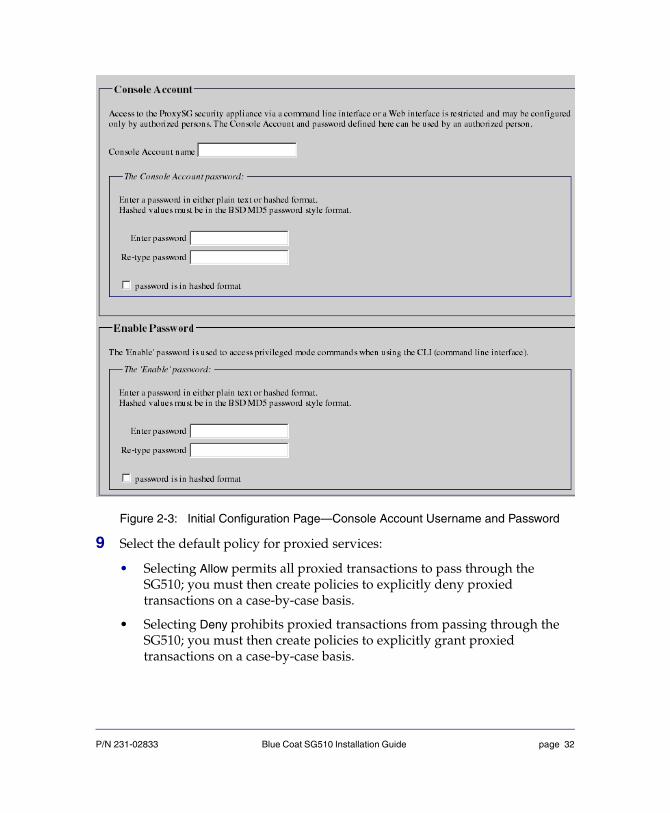
Figure 2-3: Initial Configuration Page—Console Account Username and Password
9 Select the default policy for proxied services:
• Selecting Allow permits all proxied transactions to pass through the SG510; you must then create policies to explicitly deny proxied transactions on a case-by-case basis.
• Selecting Deny prohibits proxied transactions from passing through the SG510; you must then create policies to explicitly grant proxied transactions on a case-by-case basis.
P/N 231-02833 Blue Coat SG510 Installation Guide page 32
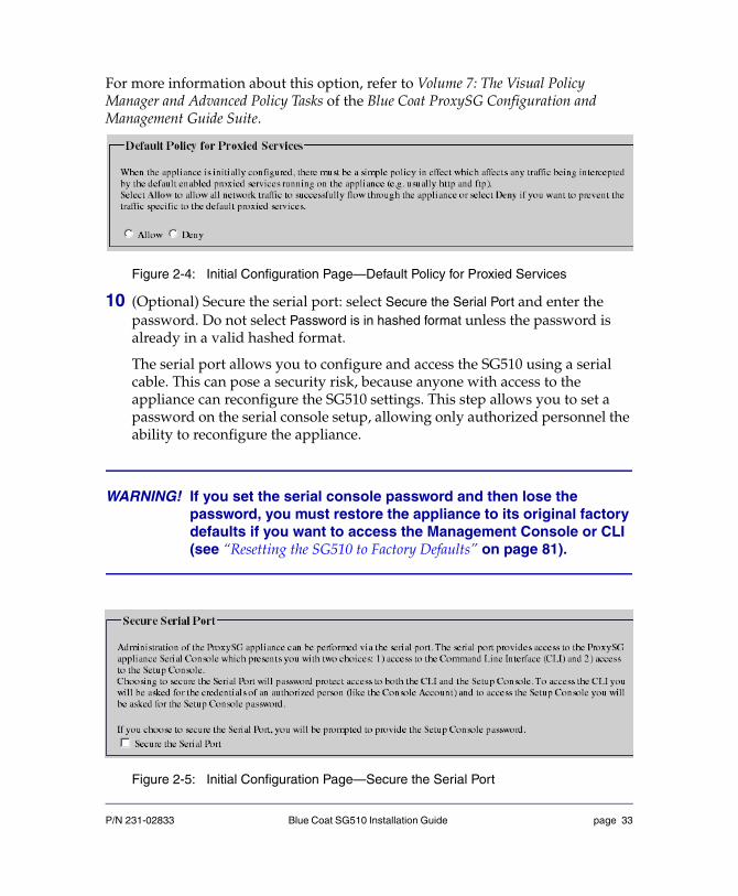
For more information about this option, refer to Volume 7: The Visual Policy Manager and Advanced Policy Tasks of the Blue Coat ProxySG Configuration and Management Guide Suite.
Figure 2-4: Initial Configuration Page—Default Policy for Proxied Services
10 (Optional) Secure the serial port: select Secure the Serial Port and enter the password. Do not select Password is in hashed format unless the password is already in a valid hashed format.
The serial port allows you to configure and access the SG510 using a serial cable. This can pose a security risk, because anyone with access to the appliance can reconfigure the SG510 settings. This step allows you to set a password on the serial console setup, allowing only authorized personnel the ability to reconfigure the appliance.
WARNING! If you set the serial console password and then lose the password, you must restore the appliance to its original factory defaults if you want to access the Management Console or CLI (see “Resetting the SG510 to Factory Defaults” on page 81).
Figure 2-5: Initial Configuration Page—Secure the Serial Port
P/N 231-02833 Blue Coat SG510 Installation Guide page 33

11 Click Configure Device.
• If a dialog appears with the message Errors Found, click OK and correct the errors in the Initial Configuration page. Click Configure Device again.
• If a new browser window appears with the message The initial configuration was not established, note the error messages in this window, close it, and fix the appropriate data in the Initial Configuration page. Click Configure Device again.
• If a new browser window appears with the message ProxySG Initial Configuration was successful, you have successfully completed initial configuration. This window provides details about accessing the SG510 Management Console (such as the Management Console SHA1 fingerprint). Save this information for future reference. Close the new browser window and the Initial Configuration page.
Figure 2-6: Successful Initial Configuration Page
When you have set the basic networking parameters and connected the SG510 to the network, you are ready to fully configure the appliance. For a list of all CLI commands, refer to the Blue Coat ProxySG Command Line Interface Reference. For information about configuring and administering the SG510 (including information about setting policies that will explicitly grant or deny proxied
P/N 231-02833 Blue Coat SG510 Installation Guide page 34
transactions), refer to the Blue Coat ProxySG Configuration and Management Guide Suite.
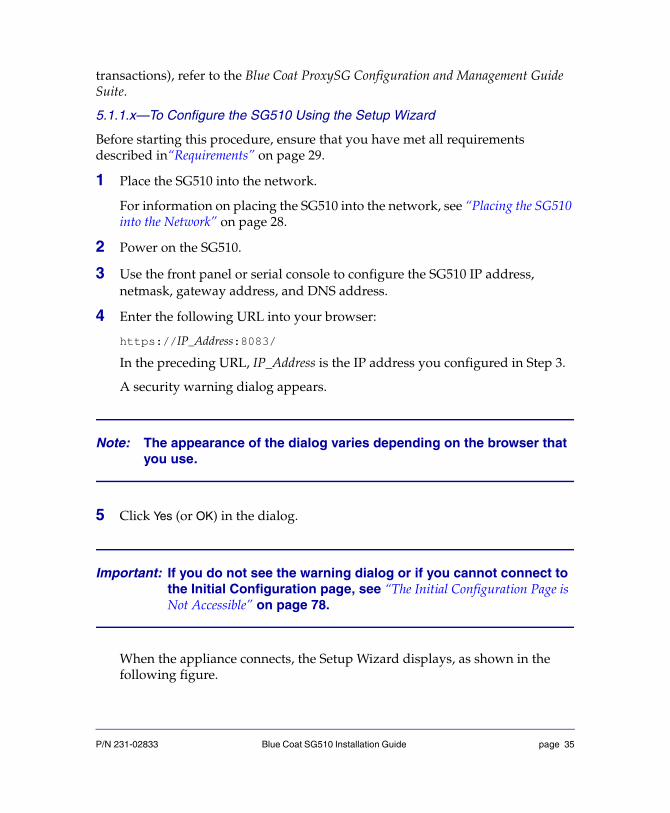
5.1.1.x—To Configure the SG510 Using the Setup Wizard
Before starting this procedure, ensure that you have met all requirements described in“Requirements” on page 29.
1 Place the SG510 into the network.
For information on placing the SG510 into the network, see “Placing the SG510 into the Network” on page 28.
2 Power on the SG510.
3 Use the front panel or serial console to configure the SG510 IP address, netmask, gateway address, and DNS address.
4 Enter the following URL into your browser:
https://IP_Address:8083/
In the preceding URL, IP_Address is the IP address you configured in Step 3.
A security warning dialog appears.
Note: The appearance of the dialog varies depending on the browser that you use.
5 Click Yes (or OK) in the dialog.
Important: If you do not see the warning dialog or if you cannot connect to the Initial Configuration page, see “The Initial Configuration Page is Not Accessible” on page 78.
When the appliance connects, the Setup Wizard displays, as shown in the following figure.
P/N 231-02833 Blue Coat SG510 Installation Guide page 35

6 Enter information on each screen, as prompted.
Each page is described; some pages include mouse-over help. If you entered network settings from the serial console, they are already filled in. To complete the Setup Wizard you must:
a. Enter the console access information.
b. Enter the CLI Enable password.
c. (Optional but highly recommended) Secure the serial port.
d. Enter the network settings:
❖ IP Address
❖ Subnet Mask
❖ Gateway
❖ DNS Server
e. (Optional) Configure the Application Delivery Network (ADN) settings.
The ADN settings optimize the delivery of applications over the WAN.
f. Select the traffic types that the appliance should intercept.
g. Set the initial policy.
P/N 231-02833 Blue Coat SG510 Installation Guide page 36

h. Confirm the settings and click Configure.
Note: The Web-based wizard is available only for initial appliance configuration (or following a reset to factory defaults). After you click Configure during the final step, the wizard is no longer available.
P/N 231-02833 Blue Coat SG510 Installation Guide page 37
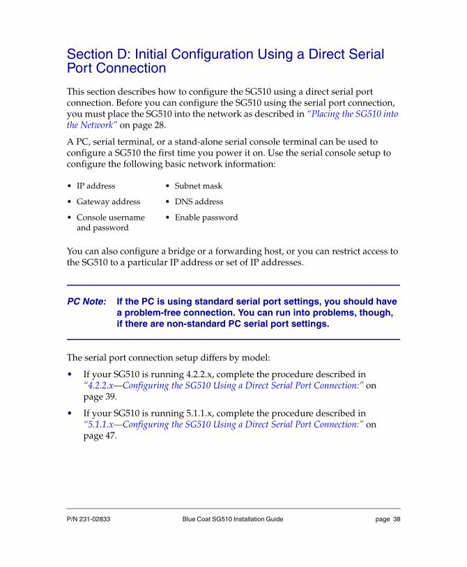
Section D: Initial Configuration Using a Direct Serial Port Connection
This section describes how to configure the SG510 using a direct serial port connection. Before you can configure the SG510 using the serial port connection, you must place the SG510 into the network as described in “Placing the SG510 into the Network” on page 28.
A PC, serial terminal, or a stand-alone serial console terminal can be used to configure a SG510 the first time you power it on. Use the serial console setup to configure the following basic network information:
You can also configure a bridge or a forwarding host, or you can restrict access to the SG510 to a particular IP address or set of IP addresses.
PC Note: If the PC is using standard serial port settings, you should have a problem-free connection. You can run into problems, though, if there are non-standard PC serial port settings.
The serial port connection setup differs by model:
• If your SG510 is running 4.2.2.x, complete the procedure described in “4.2.2.x—Configuring the SG510 Using a Direct Serial Port Connection:” on page 39.
• If your SG510 is running 5.1.1.x, complete the procedure described in “5.1.1.x—Configuring the SG510 Using a Direct Serial Port Connection:” on page 47.
• IP address • Subnet mask
• Gateway address • DNS address
• Console username and password
• Enable password
P/N 231-02833 Blue Coat SG510 Installation Guide page 38

4.2.2.x—Configuring the SG510 Using a Direct Serial Port Connection:
Do the following procedure by reading the on-screen material and entering data where necessary. In the procedure below, places that require you to enter data are illustrated by example entries in bold text.
1 Power on and connect (a) a serial terminal or (b) a PC as described below (the SG510 must be powered off):
Serial terminal: Connect the terminal’s serial cable to the SG510’s serial console port; start the terminal and verify that it is set using the RS-232C parameters defined in the following table.
RS-232C Parameters
PC: Connect the serial cable that came with the SG510 to a serial port on the PC and to the SG510’s serial console port; start the PC, open a terminal emulator (such as HyperTerminal), and connect to the serial port to which you attached the cable. Create and name a new connection (either a COM or TCP/IP), and verify that the port is set using the parameters described in the table above.
2 Power on the SG510 and wait for the system to finish booting.
Parameter Setting
Baud rate 9600 bps
Data bits 8
Parity none
Stop bits 1
Flow control none
Smooth-scroll disabled
Emulation VT 100
P/N 231-02833 Blue Coat SG510 Installation Guide page 39

The following configuration alert displays:
Figure 2-7: Serial Port Setup—Configuration Alert
3 Press the computer keyboard <Enter> key three times.
When the Welcome to the SG510 Appliance Setup Console prompt appears, the system is ready for the first-time network configuration.
Five screens display, one at a time, as shown in the following steps.
4 On page 1, indicate whether you want to configure a bridge; enter an interface number, and enter the values as indicated for the four network settings.
Note: If you enter YES to configure a bridge, you must also configure at least one bridge port and associate a network interface with it.
******************* CONFIGURATION ALERT ******************
System startup cannot continue for one of these reasons:
(a) Need at least one adapter (or bridge) configuredwith an IP address and subnet.
(b) Need the console password and enable password.
********** SYSTEM STARTUP TEMPORARILY SUSPENDED *********
Press "enter" three times to activate the serial console
P/N 231-02833 Blue Coat SG510 Installation Guide page 40
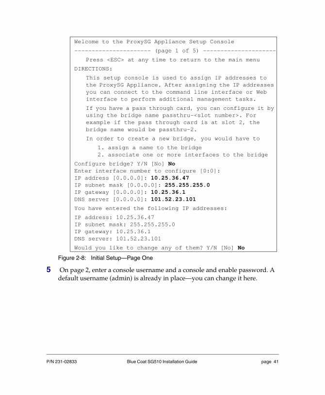
Figure 2-8: Initial Setup—Page One
5 On page 2, enter a console username and a console and enable password. A default username (admin) is already in place—you can change it here.
Welcome to the ProxySG Appliance Setup Console
---------------------- (page 1 of 5) ---------------------
Press <ESC> at any time to return to the main menu
DIRECTIONS:
This setup console is used to assign IP addresses to the ProxySG Appliance. After assigning the IP addresses you can connect to the command line interface or Web interface to perform additional management tasks.
If you have a pass through card, you can configure it by using the bridge name passthru-<slot number>. For example if the pass through card is at slot 2, the bridge name would be passthru-2.
In order to create a new bridge, you would have to
1. assign a name to the bridge2. associate one or more interfaces to the bridge
Configure bridge? Y/N [No] NoEnter interface number to configure [0:0]:IP address [0.0.0.0]: 10.25.36.47IP subnet mask [0.0.0.0]: 255.255.255.0IP gateway [0.0.0.0]: 10.25.36.1DNS server [0.0.0.0]: 101.52.23.101
You have entered the following IP addresses:
IP address: 10.25.36.47IP subnet mask: 255.255.255.0IP gateway: 10.25.36.1DNS server: 101.52.23.101
Would you like to change any of them? Y/N [No] No
P/N 231-02833 Blue Coat SG510 Installation Guide page 41

Usernames and passwords can each be from 1 to 64 characters in length, and that passwords that contain special characters (such as an exclamation point) must be in quotes.
Figure 2-9: Initial Setup—Page Two
Note: For maximum security, you should restrict physical access to the SG510. After initial configuration, you can change the workstation restriction settings through the security commands in the CLI or the Console Access tab in the Management Console. You can add or remove IP addresses or you can enable or disable workstation restrictions. For details, refer to Volume 5: Securing the ProxySG in the Blue Coat ProxySG Configuration and Management Guide Suite.
--------------------- (page 2 of 5) --------------------
Press <ESC> at any time to return to the main menu
DIRECTIONS:
The console username, password and enable password are special administrative credentials which can be used to log in to the command line interface or web management interface.
WARNING - The console password and enable password are not defined.
The system cannot start up until these are defined.
You must configure the console user account now.
Enter console username: name123Enter console password: ”******”Verify console password: ”******”Enter enable password: ”******”Verify enable password: ”******”
P/N 231-02833 Blue Coat SG510 Installation Guide page 42

6 (not recommended) For maximum security, you can secure the serial port.
The serial port allows you to configure and access the SG510 using a serial cable. This can pose a security risk because anyone with access to the appliance can reconfigure the settings. This optional step sets a password on the serial console setup, allowing only authorized personnel the ability to reconfigure the appliance. This is not recommended.
Note: If you forget the serial port password for a SG510, you cannot get access to the SG510.
Figure 2-10: Initial Setup—Secure the Serial Port (not recommended)
Do you want to secure the serial port? Y/N [Yes] YesEnter setup password: ”******”Verify setup password: ”******”
WARNING:
If you continue and enable the secure serial port it will not be possible to enter the setup console without the setup password. If the setup password is lost, assistance from Blue Coat Systems will be required and all system configuration may be lost. It is recommended that this password be stored in a physically secure location. Access to the CLI on the serial port will challenge for credentials.
To enable the secure serial port, re-enter the setup password: ”******”
P/N 231-02833 Blue Coat SG510 Installation Guide page 43
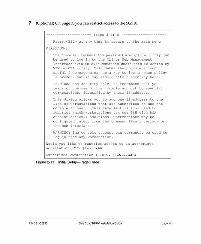
7 (Optional) On page 3, you can restrict access to the SG510.
Figure 2-11: Initial Setup—Page Three
--------------------- (page 3 of 5) --------------------
Press <ESC> at any time to return to the main menu
DIRECTIONS:
The console username and password are special: they can be used to log in to the CLI or Web Management interface even in circumstances where this is denied by VPM or CPL policy. This makes the console account useful in emergencies, as a way to log in when policy is broken, but it may also create a security hole.
To close the security hole, we recommend that you restrict the use of the console account to specific workstations, identified by their IP address.
This dialog allows you to add one IP address to the list of workstations that are authorized to use the console account. (This same list is also used to restrict which workstations can use SSH with RSA authentication.) Additional workstations may be configured later, from the command line interface or the Web interface.
WARNING: The console account can currently be used to log in from any workstation.
Would you like to restrict access to an authorized workstation? Y/N [Yes] Yes
Authorized workstation [0.0.0.0]:10.2.33.1
P/N 231-02833 Blue Coat SG510 Installation Guide page 44
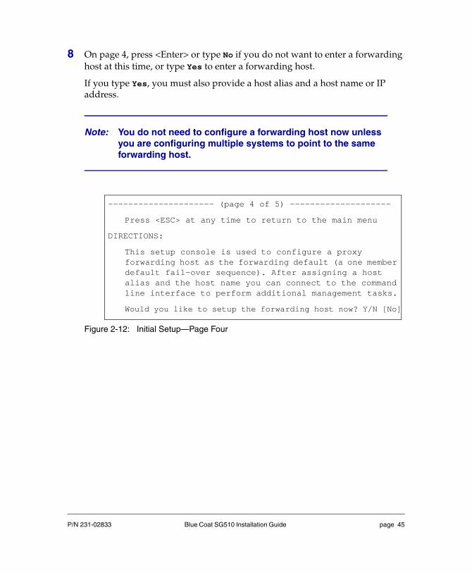
8 On page 4, press <Enter> or type No if you do not want to enter a forwarding host at this time, or type Yes to enter a forwarding host.
If you type Yes, you must also provide a host alias and a host name or IP address.
Figure 2-12: Initial Setup—Page Four
Note: You do not need to configure a forwarding host now unless you are configuring multiple systems to point to the same forwarding host.
--------------------- (page 4 of 5) --------------------
Press <ESC> at any time to return to the main menu
DIRECTIONS:
This setup console is used to configure a proxy forwarding host as the forwarding default (a one member default fail-over sequence). After assigning a host alias and the host name you can connect to the command line interface to perform additional management tasks.
Would you like to setup the forwarding host now? Y/N [No]
P/N 231-02833 Blue Coat SG510 Installation Guide page 45

Page 5 displays. This page explains how to access the SG510 from an SSH Client or with a Web browser (see “Logging on to the SG510” on page 62 for more information).
Figure 2-13: Initial Setup—Page Five
9 To log in to the serial console right away, press <Enter> three times.
A menu displays, offering two choices:
1) Command Line Interface2) Setup Console
10 Enter 1 to select the CLI (see “Logging on to the SG510 CLI” on page 64 for information about using the SG510 CLI). To access the SG510 Management Console, enter the following address into your Web browser:
https://[IP Address]:8082/
where [IP Address] is the IP address that you configured for this SG510 in Step 4.
See “Logging on to the SG510 Management Console” on page 62 for more information about accessing the SG510.
---------------------- (page 5 of 5) ---------------------
DIRECTIONS:
The ProxySG Appliance has been successfully configured to use IP address: "10.25.36.47"
You can connect to the command line interface or Web interface to perform additional management tasks.
To connect to the command line interface, open the following location from your SSH application: 10.9.16.85
To connect to the Web management interface, go to the following location with your web browser: https://10.9.16.85:8082/
---------------- CONFIGURATION COMPLETE ------------------
Press "enter" three times to activate the serial console
P/N 231-02833 Blue Coat SG510 Installation Guide page 46

5.1.1.x—Configuring the SG510 Using a Direct Serial Port Connection:
Do the following procedure by reading the on-screen material and entering data where necessary. In the procedure below, places that require you to enter data are illustrated by example entries in bold text.
1 Power on and connect the serial terminal or PC as described below (the SG510 must be powered off):
Serial terminal: Connect the terminal’s serial cable to the SG510’s serial console port; start the terminal and verify that it is set using the parameters described below.
RS-232C Parameters
PC: Connect a serial cable to a serial port on the PC and to the SG510’s serial console port; start the PC, open a terminal emulator (such as HyperTerminal), and connect to the serial port to which you attached the cable. Create and name a new connection (either a COM or TCP/IP), and verify that the port is set using the parameters described in the preceding table.
If you have set flow control to none, and if you have smooth-scroll as an option in your terminal settings, you can disable smooth-scroll in your terminal settings to reduce the chance of losing output.
2 Power on the SG510 and wait for the system to finish booting.
Parameter Setting
Baud rate 9600 bps
Data bits 8
Parity none
Stop bits 1
Flow control none
Smooth-scroll disabled
Emulation VT 100
P/N 231-02833 Blue Coat SG510 Installation Guide page 47

The following configuration alert displays:
Figure 2-14: Initial Setup—Configuration Alert
3 Press <Enter> three times.
When the Welcome to the ProxySG Appliance Setup Console prompt appears, the system is ready for the first-time network configuration.
4 On page 1, enter the interface number, IP address, IP subnet mask, IP gateway, and DNS server parameters.
****************** CONFIGURATION ALERT ******************
System startup cannot continue for one of these reasons:
(a) Need at least one adapter (or bridge) configured with an Iaddress and
subnet.
(b) Need the console password and enable password.
********* SYSTEM STARTUP TEMPORARILY SUSPENDED *********
Press "enter" three times to activate the serial console
P/N 231-02833 Blue Coat SG510 Installation Guide page 48

Figure 2-15: Initial Setup—Page One
5 On page 2, you are asked if you want to finish configuration using the Setup Wizard.
Figure 2-16: Initial Setup—Page Two
Welcome to the ProxySG Appliance Setup Console
--------------------- (page 1 of 5) --------------------
Press <ESC> at any time to return to the main menu
DIRECTIONS:
This setup console is used to assign IP addresses to the ProxySAppliance. After assigning the IP addresses you can connect to command line interface or Web interface to perform additional management tasks.
Enter interface number to configure [0:0]:IP address [0.0.0.0]: 10.25.36.47IP subnet mask [255.255.255.0]: 255.255.255.0IP gateway [0.0.0.0]: 10.25.36.1DNS server [0.0.0.0]: 101.52.23.100
You have entered the following IP addresses:
IP address: 10.25.36.47IP subnet mask: 255.255.255.0IP gateway: 10.25.36.1DNS server: 101.52.23.101
Would you like to change any of them? Y/N [No] N
--------------------- (page 2 of 5) --------------------
A comprehensive Setup Wizard is available if you use yourWeb browser. You can either use the Web Setup Wizard or youcan continue the initial configuration using this serial console.Note that this serial console initial configuration methodcontains a subset of the configuration options available in theWeb Setup Wizard.
P/N 231-02833 Blue Coat SG510 Installation Guide page 49

If you choose to use the Setup Wizard, go to “5.1.1.x—To Configure the SG510 Using the Setup Wizard” on page 35.
6 On page 3, enter a console username and a console and enable password. A default username (admin) is already in place—you can change it here.
Usernames and passwords can each be from 1 to 64 characters in length. Passwords that contain special characters (such as an exclamation point) must be in quotes.
Figure 2-17: Initial Setup—Page Three
7 (not recommended) For maximum security, secure the serial port.
The serial port allows you to configure and access the SG510 using a serial cable. This can pose a security risk because anyone with access to the appliance can reconfigure the SG510 settings. This optional step sets a password for the serial console setup, allowing only authorized personnel the ability to reconfigure the appliance.
---------------------- (page 3 of 5) ---------------------
Press <ESC> at any time to return to the main menu
DIRECTIONS:
The console username, password and enable password are special administrative credentials which can be used to log in to the commanline interface or web management interface.
WARNING - The console password and enable password are not definedThe system cannot start up until these are defined.
You must configure the console user account now.
Enter console username [admin]: name123Enter console password: ”******”Verify console password: ”******”Enter enable password: ”******”Verify enable password: ”******”
P/N 231-02833 Blue Coat SG510 Installation Guide page 50

WARNING! If you set the serial console password and then lose the password, you must restore the appliance to its original factory defaults to access the Management Console or CLI (see “Resetting the SG510 to Factory Defaults” on page 81).
Figure 2-18: Initial Setup—Secure the Serial Port (Optional)
8 (Optional) On page 4, you can restrict access to the SG510.
Note: For maximum security, you should restrict physical access to the SG510.
Do you want to secure the serial port? Y/N [Yes] YEnter setup password: ”******”Verify setup password: ”******”
WARNING:
If you continue and enable the secure serial port it will not be possible to enter the setup console without the setup password. If the setup password is lost, assistance from Blue Coat Systems will be required and all system configuration may be lost. It is recommended that this password be stored in a physically secure location. Access to the CLI on the serial port will challenge for credentials.
To enable the secure serial port, re-enter the setup password: ”******”
P/N 231-02833 Blue Coat SG510 Installation Guide page 51

Figure 2-19: Initial Setup—Page Four
Page 5 displays. This page explains how to access the SG510 from an SSH Client or with a Web browser. See “Logging on to the SG510” on page 62 for more information.
--------------------- (page 4 of 5) --------------------
Press <ESC> at any time to return to the main menu
DIRECTIONS:
The console username and password are special: they can be used tlog in to the CLI or Web Management interface even in circumstancwhere this is denied by VPM or CPL policy. This makes the consoleaccount useful in emergencies, as a way to log in when policy is broken, but it may also create a security hole.
To close the security hole, we recommend that you restrict the use the console account to specific workstations, identified by their address.
This dialog allows you to add one IP address to the list of workstations that are authorized to use the console account. (Thisame list is also used to restrict which workstations can use SSHwith RSA authentication.) Additional workstations may be configurlater, from the command line interface or the Web interface.
WARNING: The console account can currently be used to log in from aworkstation.
Would you like to restrict access to an authorized workstation? Y[Yes] Y
Authorized workstation [0.0.0.0]:10.2.33.1
P/N 231-02833 Blue Coat SG510 Installation Guide page 52

Figure 2-20: Initial Setup—Page Five
9 To log in to the serial console right away, press <Enter> three times.
A menu displays offering two choices:
1) Command Line Interface2) Setup Console
10 Access the CLI or Management Console:
• Enter 1 in the serial console menu to select the CLI.
See “Logging on to the SG510 CLI” on page 64 for information about using the SG510 CLI.
• To access the SG510 Management Console, enter the following address into your Web browser:
https://proxysg_IP:8082/
where proxysg_IP is the IP address that you configured for this SG510.
See “Logging on to the SG510 Management Console” on page 62 for more information about accessing the SG510.
When you have set the basic networking parameters and connected the SG510 to the network, you are ready to fully configure the appliance. For a list of all CLI commands, refer to the Blue Coat ProxySG Command Line Interface Reference. For
--------------------- (page 5 of 5) --------------------
DIRECTIONS:
The ProxySG Appliance has been successfully configured to use IP address: "10.25.36.47"
You can connect to the command line interface or Web interface to perform additional management tasks.
To connect to the command line interface, open the following location from your SSH application: 10.25.36.47
To connect to the Web management interface, go to the following location with your web browser: https://10.25.36.47:8082/
--------------- CONFIGURATION COMPLETE -----------------
Press "enter" three times to activate the serial console
P/N 231-02833 Blue Coat SG510 Installation Guide page 53

information about configuring and administering the SG510 (including information about setting policies that will explicitly grant or deny proxied transactions), refer to the Blue Coat ProxySG Configuration and Management Guide Suite.
P/N 231-02833 Blue Coat SG510 Installation Guide page 54

Section E: Configuring the SG510 from a Remote Location
Important: The remote configuration procedure pertains only to 4.2.2.x or later. If you are running 5.1.1.x or later, you must configure the SG510 using the front panel, Web Setup Wizard, or serial console. See “5.1.1.x—To Configure the SG510 Using the Setup Wizard” on page 35 and “5.1.1.x—Configuring the SG510 Using a Direct Serial Port Connection:” on page 47 for more information.
The goal of the remote configuration method is to allow an administrator to provide the initial configuration settings of an appliance before the physical installation of the system. Using the remote configuration method, an administrator uses an HTML page to specify the initial configuration settings, which are then embedded into a URL. To configure the appliance, a remote installer only has to place the appliance into the network and click the generated URL. After the appliance has its initial configuration, the administrator can finish configuring the appliance—either remotely or locally.
The remote configuration method is useful in the following circumstances:
• You have appliances destined for multiple locations but do not want to have to first ship them to a single location for initial configuration.
• The personnel at the remote locations are not technical and cannot be trusted to properly configure the appliance.
Configuring the SG510 remotely is a two-step process—use the following procedures if you want to enter the SG510 configuration parameters from a remote location (Step 1), and then have an on-site administrator place the SG510 into the network and complete the configuration (Step 2).
Step One—Enter the Remote Configuration Parameters Using a Web BrowserPerform this procedure if you plan to enter configuration parameters for the SG510 from a remote location and then have an on-site administrator place the SG510 into the network and complete the configuration.
P/N 231-02833 Blue Coat SG510 Installation Guide page 55

To Enter Configuration Parameters from a Remote Location:
1 Enter the following URL into your browser:
http://download.bluecoat.com/initial-remote/initial-remote.html
2 The SG510 Initial Configuration Setup for Remote Appliances window opens.
3 Enter the network parameters for the remote appliance.
Figure 2-21: Remote Initial Configuration Page—Network Parameters
P/N 231-02833 Blue Coat SG510 Installation Guide page 56

4 Enter the Console Account username and password; enter the Enable (privileged mode) password.
• If you enter the passwords in plain text, click hash the password for each password.
• If you enter the passwords in hashed format, select password is in hashed format for each password. A hashed password must be in the BSD MD5 password format.
Figure 2-22: Remote Initial Configuration Page—Console Account Username and Password
P/N 231-02833 Blue Coat SG510 Installation Guide page 57

5 Select the default policy for proxied services:
• Selecting Allow permits any and all proxy-types access to the SG510; you must then create policies to explicitly deny access on a case-by-case basis.
• Selecting Deny prohibits proxy-type access to the SG510; you must then create policies to explicitly grant access on a case-by-case basis.
For more information about this option, refer to Volume 7: The Visual Policy Manager and Advanced Policy Tasks of the Blue Coat ProxySG Configuration and Management Guide Suite.
Figure 2-23: Remote Initial Configuration Page—Default Policy for Proxied Services
6 (Optional) Secure the serial port: select Secure the Serial Port and enter the password.
• If you enter the password in plain text, click hash the password.
• If you enter the password in hashed format, select password is in hashed format. A hashed password must be in the BSD MD5 password format
The serial port allows you to configure and access the SG510 using a serial cable. This can pose a security risk, because anyone with access to the appliance can reconfigure the SG510 settings. This optional step allows you to set a password on the serial console setup, allowing only authorized personnel the ability to reconfigure the appliance.
WARNING! If you set the serial console password and then lose the password, you must restore the appliance to its original factory defaults to access the Management Console or CLI (see “Resetting the SG510 to Factory Defaults” on page 81).
P/N 231-02833 Blue Coat SG510 Installation Guide page 58

Figure 2-24: Remote Initial Configuration Page—Secure the Serial Port
7 Click Generate URLs.
• If a dialog appears with the message Errors Found, click OK and correct the errors in the Initial Configuration page. Click Generate URLs again.
• If all the fields in the form are correct, a section called Configuration URLs appears at the bottom of the page. A list of URLs are provided in this section—one for each of the five potential network addresses to which the SG510 might respond. Which URL works best depends on the network topology into which the SG510 is placed. At least one of the URLs should work in your network environment.
8 Copy and send one or more of the URLs to the local administrator who will complete the configuration. Verify that the local administrator has all required information, such as how to properly place the SG510 into the network and, if necessary, how to modify the network parameters on his or her PC so that the generated URL works to configure the appliance.
Step Two—Complete the ConfigurationPerform the following procedure if you are at the same location as the SG510 and you are planning to complete the initial configuration using a URL provided to you by a remote administrator.
To Configure the SG510 Using a Remotely Generated URL:
1 Place the SG510 into your network using one of the following methods:
• Change the IP address of the PC so that it is on one of the subnets the appliance uses for initial configuration:
https://10.0.0.254:8083/
P/N 231-02833 Blue Coat SG510 Installation Guide page 59

https://172.16.0.254:8083/
https://192.168.0.254:8083/
https://192.168.1.254:8083/
• On the PC, create a static route to the SG200. Refer to “Creating A Static Route to the SG510” on page 79 for information about creating a static route.
• Deploy the SG200 inline using the bridging feature.
Refer to Volume 2: Getting Started of the Blue Coat ProxySG Configuration and Management Guide Suite for more information about these deployments.
2 On your PC, open a Web browser using the Initial Configuration URL that you received from the remote administrator. If the URL is a link in an e-mail, click the link.
• If a new browser window appears with the message ProxySG Initial Configuration was successful, you have successfully completed initial configuration. This window provides details about accessing the SG510 Management Console, including the Management Console SHA1 fingerprint (see Figure 2-6 on page 34). Save this information for future reference. Close the new browser window and the Initial Configuration page.
• If the URL was not entered correctly or was corrupted, an error page displays. Fix the problem indicated and click Configure Device again.
• If the SG510 is unavailable (for example, it is not connected to the network properly or is already configured), you either fail to connect to the Web page (and see a browser error page), or you see a Blue Coat Web page that describes some of the potential problems you might have. Fix
P/N 231-02833 Blue Coat SG510 Installation Guide page 60

the problem, if possible, and click Configure Device again. If you cannot fix the problem, contact the remote administrator for assistance.
Note: You might need to modify the network parameters on your PC so that the URL works to configure the SG510. Consult the remote administrator if you suspect that this is required.
When you have set the basic networking parameters and connected the SG510 to the network, you are ready to fully configure the appliance. For a list of all CLI commands, refer to the Blue Coat ProxySG Command Line Interface Reference. For information about configuring and administering the SG510 (including information about setting policies that will explicitly grant or deny proxied transactions), refer to the Blue Coat ProxySG Configuration and Management Guide Suite.
P/N 231-02833 Blue Coat SG510 Installation Guide page 61

Section F: Logging on to the SG510
After the SG510 is configured, the LCD will begin to cycle through and display various messages, such as CPU Utilization and Freshness.
After you have completed the initial configuration and connected the SG510 to the network, you must log on to the SG510 to fully configure the appliance. There are two ways to do this.
• Use a browser to access the SG510 Management Console Web interface.
• Use a direct serial connection or an SSH Client to access the SG510 command-line interface (CLI).
Important: Blue Coat recommends that you set up a secure SSL connection for greater security. For instructions, refer to Volume 5: Securing the ProxySG in the Blue Coat ProxySG Configuration and Management Guide Suite.
Logging on to the SG510 Management Console
The Management Console is a graphical interface for configuring and managing all aspects of the SG510. You can log on to the Management Console using a browser.
To Log on to the Management Console Using a Browser:
1 Start the SG510.
2 Open a browser. The SG510 supports Microsoft® Internet Explorer 6.0, Netscape® Communicator 7.2, and Firefox 1.0.
3 Enter the IP address configured during initial configuration, followed by the port number 8082. For example, enter: https://10.25.36.47:8082.
4 Click Yes in the Security Alert dialog; enter a username and password in the Enter Network Password dialog that displays. If the username has not been changed, the default is admin. The password is the one you wrote down or configured during initial configuration.
P/N 231-02833 Blue Coat SG510 Installation Guide page 62

The SG510 home page displays.
5 Click the Management Console link from the top of the list on the left.
The Management Console page displays.
Figure 2-25: The Management Console Page
6 Navigate among Configuration, Maintenance, and Statistics by clicking one of the three tabs near the top of the screen; click the links on the left to select a configurable component. Click the Help button on any screen to display information for that screen.
The online Help contains the complete text of the Blue Coat ProxySG Configuration and Management Guide Suite. Use the Contents and Index links to navigate through the manual.
When you have set the basic networking parameters and connected the SG510 to the network, you are ready to fully configure the appliance. Refer to the Blue Coat ProxySG Configuration and Management Guide Suite for information about configuring and administering the SG510. For information about configuring explicit or transparent proxies for the SG510, refer to Volume 3: Proxies and Proxy Services of the Blue Coat ProxySG Configuration and Management Guide Suite. For a list of all CLI commands, refer to the Blue Coat ProxySG Command Line Interface Reference.
P/N 231-02833 Blue Coat SG510 Installation Guide page 63

Logging on to the SG510 CLI
You can connect to the SG510 CLI (a) by using a direct serial connection or (b) by using an SSH client, such as PuTTY or F-Secure. To connect to the SG510 CLI using Telnet, you must first enable the Telnet-Console. Refer to the Volume 3: Proxies and Proxy Services of the Blue Coat ProxySG Configuration and Management Guide Suite.
Note: The CLI uses two passwords: The console password is required to establish a connection to the interface, and the enable password can be set to restrict access to the privileged mode configuration options. If you forget the username or password, you can reset them using either the front panel control buttons and LCD or a serial terminal or PC.
Using a Direct Serial Connection to Connect to the SG510 CLI
1 To set up the serial connection, complete steps 1 and 2 in the section “Initial Configuration Using a Direct Serial Port Connection” on page 38.
2 After the system has finished booting, press the computer keyboard Enter key three times. The following text displays:
Welcome to the Appliance Serial Console
Version: SGOS 4.2.2.0, Release id: 12345
------------------------- MENU---------------------------
1) Command Line Interface2) Setup Console
--------------------------------------------------------
Enter option:
3 Enter 1 to select the Command Line Interface option.
4 Enter the username and password when prompted. If the username has not been changed, the default is admin. The password is the one you wrote down or configured during initial configuration.
P/N 231-02833 Blue Coat SG510 Installation Guide page 64

5 At the command prompt, enter enable, then enter the enable password that you wrote down or configured during initial configuration:
SGOS>enableEnable Password:SGOS#
You are now in privileged mode.
6 At the privileged-mode command prompt, enter configure terminal to configure SG510 settings:
SGOS# configure terminalEnter configuration commands, one per line. End with CTRL-Z.SGOS#(config)
Refer to the Blue Coat ProxySG Configuration and Management Guide Suite for information about configuring and administering the ProxySG.
Using an SSH Client to Connect to the SG510 CLI
1 Start the ProxySG.
Note: You must already have an SSH Client installed before you proceed with the steps below.
2 Launch your SSH Client—enter the following settings as necessary:
• The IP address that you configured during initial configuration.
• A port number, if necessary. (Port 22 is the default.)
• The username and password. If the username has not been changed, the default is admin. The password is the one you wrote down or configured during initial configuration.
3 At the command prompt, enter enable, then enter the enable password that you wrote down or configured during initial configuration:
SGOS>enableEnable Password:SGOS#
You are now in privileged mode.
P/N 231-02833 Blue Coat SG510 Installation Guide page 65

4 At the privileged-mode command prompt, enter configure terminal to configure ProxySG settings:
SGOS#configure terminal[Enter configuration commands, one per line. End with CTRL-Z.]SGOS#(config)
Refer to the Blue Coat ProxySG Configuration and Management Guide Suite for information about configuring and administering the ProxySG.
P/N 231-02833 Blue Coat SG510 Installation Guide page 66

Section G: Configuring a Front-Panel PIN
The front panel allows you to reconfigure the initial settings of the SG510, which can represent a security risk. Setting a front-panel PIN limits access to authorized personnel only.
This procedure is only available through the CLI—you cannot set a front-panel PIN through the Management Console.
To Configure a Front-Panel PIN:
1 Connect to the SG510 CLI and access the privileged-mode configure commands (see “Logging on to the SG510” on page 62).
2 From the privileged mode command prompt, change the SG510 front panel PIN by entering one of the following commands:
SGOS#(config) security front-panel-pin PIN
-or-
SGOS#(config) security hashed-front-panel-pin hashed_PIN
where PIN is an unhashed PIN and hashed_PIN is a PIN in hashed format. After entering one of these commands, anyone who attempts to configure the SG510 through the front panel is prompted to enter the PIN.
Note: The front-panel PIN commands are hidden commands. If you enter the commands listed above and receive an unrecognized command message, enter the following command and try again:
SGOS#(config) reveal-advanced all
P/N 231-02833 Blue Coat SG510 Installation Guide page 67

Section H: Configuring the Front-Panel LCD Behavior
The front-panel LCD turns off after 30 seconds by default. This behavior is configurable—you can set the LCD to remain on at all times, to turn off after a specified length of time, or to flash (the flash setting can be helpful if you need to find one SG510 in a room full of them).
The front-panel LCD cannot be configured through the Management Console—you must use the CLI.
To Configure the Front-Panel LCD through the CLI:
1 Open a terminal session with the SG510; at the standard-mode command prompt, enter enable and your privileged-mode password.
SGOS>enableEnable Password: ******SGOS#
2 At the privileged-mode command prompt, enter the configure terminal command to access the privileged mode configure commands:
SGOS#configure terminalSGOS#(config)
3 At the (config) prompt, enter the front-panel command to access the front-panel mode commands and to configure the front-panel LCD behavior.
SGOS#(config) front-panelSGOS#(config front-panel)SGOS#(config front-panel) backlight flashSGOS#(config front-panel) backlight state {off | on | timeout}SGOS#(config front-panel) backlight timeout seconds
P/N 231-02833 Blue Coat SG510 Installation Guide page 68

where:
flash Configures the LCD to flash. When set, the LCD continues to flash until the user presses a front panel button or the setting is changed through the CLI command no backlight flash.
The flash setting can overwrite the backlight state setting.
state off Configures the LCD to always remain off when the ProxySG is powered on. This is the default behavior.
on Configures the LCD to always remain on when the SG510 is powered on.
timeout Configures the LCD to turn off after a specified number of seconds. Use the backlight timeout seconds command (described below) to specify the number of seconds.
timeout seconds Specifies the number of seconds that the LCD remains on without activity. The backlight state timeout command specifies an LCD timeout; this command specifies the number of seconds before timeout occurs.
P/N 231-02833 Blue Coat SG510 Installation Guide page 69

P/N 231-02833 Blue Coat SG510 Installation Guide page 70

Chapter 3: Removing and Installing Disk Drives
This chapter describes how to remove and install disk drives.
Important: The SG510 only supports disk-drive upgrade packages obtained from Blue Coat Systems, Inc.
Important: You cannot hot-swap disks in the SG510; you will lose all configuration settings.
A SG510 Appliance has open slots for two disk drives. The unit ships with two blank disk-drive spacers already installed. Do not attempt to remove these blank drives.
If your original appliance came with a single disk drive, upgrade options are available from Blue Coat.
If you are upgrading your SG510 by adding (not replacing) disk drives, you can skip to “Installing a New Disk Drive” on page 73.
For initial installation of disk drives into a new SG510, see “Installing the Disk Drives” on page 12.
P/N 231-02833 Blue Coat SG510 Installation Guide page 71

Removing a Disk Drive1 Power down the SG510 by removing the power cord.
2 Press the push tabs on each side of the front-panel bezel to release the locked position of the SG510 front panel. Pull the front panel forward and down.
Figure 3-26: Access the Disk Drive Slots
3 If other equipment blocks the front panel from opening all the way, you can pull the front-panel forward, sliding out the front-panel tray until you can access the disk drives.
Figure 3-27: Access the Disk Drive Slots
4 On the disk drive to be removed, gently press the button on the right side of the disk-drive carrier to release the disk lever.
Press the push tabs on each side of the front-panel bezel
The front panel swings forward and down
Pull out the front-panel tray, if necessary, to access the disk drives
P/N 231-02833 Blue Coat SG510 Installation Guide page 72

5 Carefully pull the lever towards you to slide the disk drive out.
Figure 3-28: Slide the Disk Drive Out
Installing a New Disk DriveFollow these steps to install a new disk drive.
Note: The SG510 must be powered off before installing a new disk drive.
1 Take the new disk drive and press the button to release the lever.
2 Align the drive carrier with the guide rails of the drive slot. Using the lever, carefully insert the drive carrier into the slot.
3 When the disk meets the drive slot wall, gently rotate the lever towards the button until it latches, seating the drive firmly in place.
First press this button to release the lever
Pull the lever toward you to slide the disk drive carrier out
P/N 231-02833 Blue Coat SG510 Installation Guide page 73

4 Slide in the front panel tray, if necessary, and close the front panel.
5 Power up the SG510.
The SG510 recognizes and initializes the disk; no configuration is necessary. When the new disk is plugged in, the corresponding Disk Drive LED lights up to show that the drive is online.
P/N 231-02833 Blue Coat SG510 Installation Guide page 74

Chapter 4: Option Cards
The SG510 comes with a number of expansion slots; three option cards are available.
Dual Gigabit Ethernet 1000B-SX (optical) Card
This card provides one gigabit of throughput to the network.
Dual Gigabit Ethernet (copper) Pass-Through Card
This card is a two-port, PCI network interface card (NIC). The Pass- Through Card has three separate functions:
• It works as a standard NIC to move data in and out of the SG510.
• It provides a hardware failover mechanism in case of a power loss to or hardware or software failure in the SG510. In the event of any of the above, the Pass-Through card will physically bypass Ethernet traffic around the SG510.
• It does away with the need for a router or Layer 4 switch when the SG510 is configured for transparent proxy by working with Layer 4 redirection software in the SGOS operating system.
SSL Accelerator Card
This PCI card enables the SSL proxy service to intercept HTTPS traffic (in explicit and transparent modes) so that security measures such as authentication, virus scanning and URL filtering, and performance enhancements such as HTTP caching can be applied to HTTPS content. Additionally, the SSL proxy allows you to validate server certificates presented by various HTTPS sites at the gateway and offers information about the HTTPS traffic in the access log.
P/N 231-02833 Blue Coat SG510 Installation Guide page 75

P/N 231-02833 Blue Coat SG510 Installation Guide page 76

Chapter 5: Troubleshooting
This chapter describes how to isolate and solve common problems during the installation of the SG510.
The SG510 does not power upIf the SG510 does not power up, check the following:
• The power cord is fully inserted into the back of the SG510.
• The power cord is plugged into a working outlet or power supply.
When the SG510 is powered up and running, the Power LED on the front panel of the SG510 is on, the Disk Drive LEDs (for as many disks as are installed) are on, and the LCD displays Blue Coat when starting up and then the LCD cycles between CPU utilization and proxied traffic statistics when the SG510 is running.
Figure 5-1: SG510 Powering Up
LCD
Power LED
P/N 231-02833 Blue Coat SG510 Installation Guide page 77

The Initial Configuration Page is Not AccessibleThis is a networking problem or you entered an incorrect network address. Attempt the following:
• Verify that the SG510 is powered on.
• Verify that both interfaces have established a network link.
• If you are using a bridged deployment, verify that you entered the correct initial configuration URL: https://proxysg.bluecoat.com:8083/
• Try one of the following URLs to access the Initial Configuration page:
https://10.0.0.254:8083/
https://172.16.0.254:8083/
https://192.168.0.254:8083/
https://192.168.1.254:8083/
To use the preceding URLs, the host client has to be in the same subnet as one of the IP addresses. Or, you can add a static route on the host client.
• Verify that the browser is not proxied. To change or check the browser settings, complete one of the following steps:
• In a Windows browser, select Tools>Internet Options>Connections. Click LAN Settings and deselect Proxy server if it is selected.
• In a Firefox browser, select Tools>Options>General. Click the Connection Settings button and deselect Manual or Automatic Proxy Configuration if one of them is selected (select Direct Connection to the Internet).
• In a Netscape Communicator browser, select Edit>Preferences>Advanced>Proxies and deselect Manual or Automatic Proxy Configuration if one of them is selected (select Direct Connection to the Internet).
• Restore the appliance to its factory defaults (the Initial Configuration page is not accessible to an appliance that has already been configured). See “Resetting the SG510 to Factory Defaults” on page 81.
P/N 231-02833 Blue Coat SG510 Installation Guide page 78

Creating A Static Route to the SG510I f your SG510 is running 4.2.2.x or later and you want to use the Web-based initial configuration method, you might need to create a static route from your PC to one of the “soft” initial configuration IP addresses.
To create a static route to the SG510
1 Access the Windows command prompt.
2 Enter the following command:
C:\>route add proxySG_ip_address mask subnet_mask client_ip_address
In the preceding command, soft_ip_address is one of the “soft” IP addresses the SG510 listens for and client_ip_address is the address of the PC.
For example:
C:\>route add 10.0.0.254 mask 255.255.255.255 10.2.11.1553 Verify the static route by entering the following command:
C:\>route print
You cannot access the serial consoleIf you have connected a serial cable to the SG510 but you cannot open the serial console, do the following:
• Check cable connections.
• Check configuration information at the terminal emulator for the correct settings (see “Initial Configuration Using a Direct Serial Port Connection” on page 38 for information).
• Verify that the serial cable is a Null Modem type cable. The cable pin outs can be found at http://www.bluecoat.com/support/self-service/1/pinouts.html
• Use a different cable.
You cannot access the Management ConsoleIf the browser fails to connect to the SG510 successfully, complete the following steps to identify the problem.
• Verify that you have the correct IP address and port for the SG510 in your Web browser (the default port is 8082).
P/N 231-02833 Blue Coat SG510 Installation Guide page 79
Verify the address and port using the CLI through the Serial Console, and display the network configuration. For information on how to do this, see “Initial Configuration Using a Direct Serial Port Connection” on page 38.
• Verify that the workstation is configured and working properly by connecting to other Web sites. This test might fail if your browser is configured to use the SG510 as a proxy server and there is a problem with the SG510.
• If accessing a SG510 located on a remote network (any segment other than the segment to which the workstation is attached), verify that other servers on that network are accessible.
• Ping the IP address to verify that the SG510 is accessible from the workstation. If the SG510 does not respond to the ping, verify that the SG510 is operational (as described earlier).
A Security Warning Appears for the Initial Configuration Web PageWhen you open the Initial Configuration page, a security warning dialog appears. This warning indicates that the SG510 credentials could not be verified by a known certificate authority (such as VeriSign®). This is because the SG510 dynamically generated the self-signed credentials at the time of the last factory reset—they are not registered with a known certificate authority.
Normally, accepting such a credential represents a security risk because of the possibility of a man-in-the-middle attack. However, when you have connected your PC directly to the SG510, as described in this guide, a man-in-the-middle attack is impossible. The SG510 has not yet been configured and is connected directly to your PC. The Initial Configuration Web page is accessible only through a SG510 that has not yet been configured.
You can verify that the serial number in the credential matches the serial number printed on the SG510 if you want to be absolutely certain that you have connected to the correct device.
The SG510 certificate is no longer valid If you move the SG510 from its original location or change the IP address for any reason, the SG510’s security certificate might not be accepted the next time you open the Management Console.
P/N 231-02833 Blue Coat SG510 Installation Guide page 80

This is because the hostname no longer matches the hostname on the certificate. You must create a new certificate and then edit the HTTPS-Console service to use it.
For information about creating a new certificate and editing the HTTPS-Console service, refer to the “Configuring HTTPS Termination” and “HTTPS Console (Secure Console)” sections of the Blue Coat ProxySG Configuration and Management Guide Suite.
Resetting the SG510 to Factory DefaultsWhen the SG510 is powered on and has booted up, but an initial configuration has not yet been performed, the Power LED flashes green and amber. If the Power LED is solid green, the initial configuration has already been performed. If you did not perform an initial configuration, but the Power LED is solid green, reset the appliance to its factory defaults. Also reset the appliance if you cannot connect to the Initial Configuration page through your browser. The initial configuration Web page is accessible only to an appliance that has not been configured.
You can reset the SG510 to factory defaults using the Management Console or the CLI.
To reset the SG510 to Factory Defaults
1 Access the SG510 Management Console.
https://IP_Address:8082
Where IP_Address is the IP address of the SG510.
2 Select Maintenance>General.
P/N 231-02833 Blue Coat SG510 Installation Guide page 81

3 In the Tasks field, click Restore the configuration to defaults.
4 Click Apply.
The appliance performs a soft restart. The power LED turns amber during the restart. Wait until the reset is complete (about one minute) before trying to complete the initial configuration.
Related CLI commandsSGOS# restore-defaults factory-defaults
3
P/N 231-02833 Blue Coat SG510 Installation Guide page 82

The SG510 Does Not Come Back Up After RebootingIf the appliance is not coming back up after rebooting and the serial port is connected to terminal server (terminal concentrator) try the following:
1 Open an active session on the terminal server, noting any traffic being outputted.
2 Unplug the terminal server from the appliance.
P/N 231-02833 Blue Coat SG510 Installation Guide page 83

P/N 231-02833 Blue Coat SG510 Installation Guide page 84

Appendix A: Specifications
General SpecificationsImportant: Any modifications to the unit, unless expressly approved by Blue Coat, could void the user’s warranty.
Dimensions (Abmessungen)(L x W x H)
58 cm x 44 cm x 4.4 cm22.8 in. x 17.4 in. x 2.7 in.
Weight (Gewicht) 15 kilograms maximum33 pounds maximum
Power Input, AC(Stromversorgung)
100 - 240 VAC50 - 60 Hz6.3 - 3.0A
Processor (Prozessor) Intel® Celeron
Memory (Speicher) SDRAM DDR333Up to 2GB
Hard Drives (Festplatte) IDE SATA 1.5Gb/s
Network (Netzwerk) Two, on-board 10/100/1000 Base-T NICs (Network Interface Cards)Optional cards include the 1000B-SX
MTBF 100,000 Hours
P/N 231-02833 Blue Coat SG510 Installation Guide page 85

Environmental SpecificationsSpecification Operating (Betrieb) Non-Operating (Lagerung)
Temperature(Betriebstemeperatur)
5°C to 35°C (41°F to 95°F) -40°C to 70°C (-40°F to 158°F)
Relative Humidity(non-condensing)(Relative Luftfeuchte)
15% to 95% at 35°C (95°F) 15% to 90% at 65°C (149°F)
Maximum altitude(Hohe)
up to 3000 meters (up to 10,000 feet)
4.6 Km (15,000 ft)
P/N 231-02833 Blue Coat SG510 Installation Guide page 86
Appendix B:Regulatory Statements
Any modification to this product, unless expressly approved by Blue Coat Systems, Inc., could void the user’s authority to operate the equipment.
Do not service the proxy yourself. If you have any questions, please contact Blue Coat.
Blue Coat Corporate 420 North Mary Avenue Sunnyvale, CA 94085-4121 408.220.2200
General System CautionsTo ensure normal operation, follow these guidelines:
Top cover removal—Before removing the top cover, turn off the power.
Ventilation guidelines—Be Careful! Do not block any openings in the system to avoid overheating the system. Water caution—Be Careful! Do not get any water on the system.
System use and installation—The system is intended for use in a server room only. It is not intended be installed in individual employee work areas.
Power Cord Cautions Caution—This product is designed to work with power systems having a grounded neutral. To reduce the risk of electric shock, do not plug this product into any other type of power system. Contact a qualified electrician if you are not sure what type of power is supplied to your building.
Caution—Not all power cords have the same current ratings. Do not use the power cord provided with your equipment for any other products or use.
Caution—there is no power switch equipped on this device. The power cord serves as the primary disconnect device for the system. Be sure to plug the power cord into a grounded power outlet that is nearby the system and is readily
P/N 231-02833 Blue Coat SG510 Installation Guide page 87

accessible. Do not connect the power cord when the power supply has been removed from the system chassis.
Class A Digital WarningThis equipment has been tested and found to comply with the limits for a Class A digital device, pursuant to Part 15 of the FCC rules. These limits are designed to provide reasonable protection against harmful interference when the equipment is operated in a commercial environment. This equipment generates, uses, and can radiate radio frequency energy, and if not installed and used in accordance with the instruction manual, might cause harmful interference to radio communications. Operation of this equipment in a residential area is likely to cause harmful interference, in which case the users are required to correct the interference at their own expense.
Advertencia Digital Clase AEste equipo ha sido probado y se ha visto que se mantiene dentro de los límites de un dispositivo digital Clase A según la parte 15 de las normas de la FCC. Estos límites están designados para proveer una protección razonable contra interferencias dañinas cuando el equipo es usado en un ambiente comercial. Este equipo genera, usa y puede irradiar energía de radiofrecuencia; si no es instalado y usado de acuerdo al manual de instrucciones, puede causar interferencias perjudiciales para las comunicaciones de radio. El uso de este equipo en un área residencial puede causar interferencia perjudicial; en este caso los usuarios deberán corregir la interferencia cubriendo los gastos por ellos mismos.
EC Community EMC WarningThis is a Class A product. In a domestic environment, this product might cause radio interference in which case the user might be required to take adequate measures.
Advertencia EMC de la Comunidad ECEste es un producto Clase A En un ambiente doméstico, este producto puede causar interferencia de radio, en cuyo caso el usuario podría verse obligado a tomar medidas adecuadas.
Canadian EC EMC WarningThis Class A digital apparatus complies with Canadian ICES-003. Cet appareil numerique de la class A est conforme a la norme NMB-003 du Canada.
P/N 231-02833 Blue Coat SG510 Installation Guide page 88

Australia/New Zealand EC EMC WarningThis is a Class A product. In a domestic environment, this product might cause radio interference, in which case the user might be required to take adequate measures.
Taiwan BSMI Notification
Japan VCCI EMC Notification
Battery Warning NotificationCAUTION: Danger of explosion if battery is incorrectly placed. Replace only with the same or equivalent type recommended by the manufacturer. Dispose of used batteries according to the manufacturer’s instructions.
Connection to ports not defined for normal operation, according to this manual, might result in excessive radiated emissions. The user is then responsible for all corrective action in the event of any problem.
PRECAUCION: Peligro de explosión si la batería es colocada incorrectamente. Substituya sólo con el con el modelo original o la recomendacion del fabricante. Elimine las baterías usadas segun las instrucciones del fabricante.
La conexión a puertos no definidos para operación normal, de acuerdo a este manual, puede producir emisiones excesivas de radiación. El usuario es responsable de corregir esto en caso de cualquier problema.
ATTENTION: Il y a danger d’explosion s’il y a remplacement incorrect de la batterie. Remplacer uniquement avec une batterie de meme type ou d’un type
P/N 231-02833 Blue Coat SG510 Installation Guide page 89

equivalent recommande par le constructeur. Metter au rebut less batteries usagees conformement aux instructions du fabricant.
VORSICHT! Explosionsgefahr bei unsachgemäßem Austausch der Batterie. Ersatz nur durch denselben oder einen vom Hersteller empfohlenen glelchwertigen Typ.
Entsorgung gebrauchter Batterien nach Angaben des Herstellers.
Chinese Battery Warning Notification
China CCC Notification
LasersLocation of the laser apertures if any (Par. 6.1 3). Example: connectors for fiber optic component.
P/N 231-02833 Blue Coat SG510 Installation Guide page 90

¶ Ô ËÉ è± µ ÄÈ Îº ÎÐ Þ Ä£ ¬³ ý· ǵ õ ½Blue Coat Systems¹ «Ë ¾µ Äà ÷È ·Í ¬Ò ⣠¬· ñÔ ò¶ ¼» áÊ ¹Ó û §É ¥Ê §Ê ¹Ó ñ ¾É è± µ ÄÈ À û¡ £
A¼ ¶Ê ý ëÉ è± ¾ ¯ æ ¾ -¼ ì² â£ ¬± ¾É è± ¸ ïµ ½Á ËA¼ ¶Ê ý ëÉ è± Ï Þ¶ ± ê× ¼£ ¬· ûº ÏFCC¹ æÔ òµ Ú15Õ ÂÖ ®Ò ªÇ ó¡ £Õ âÐ ©Ï Þ¶ Ö ¼Ô ÚÌ á¹ ©º ÏÀ íµ Ä± £» ¤£ ¬Ê ¹É è± Ô ÚÉ ÌÒ µ» ·¾ ³Ï ÂÊ ¹Ó ÃÊ ±Ä ܵ Ö¿ ¹Ó к ¦ ÉÈ Å¡ £± ¾É è± ² úÉ ú¡ ¢Ê ¹Ó ò ¢Ä Ü· øÉ äÉ äÆµÄ ÜÁ ¿£ ¬È ç¹ û° ²× °º ÍÊ ¹Ó ò »· ûº ÏË µÃ ÷Ê éµ ÄÒ ªÇ ó£ ¬¿ ÉÄ Ü¶ ÔÎ ÞÏ ßµ çÍ Ð ÅÔ ì³ ÉÓ Ðº ¦ ÉÈ Å¡ £È ç¹ ûÔ Ú¾ Ó× ¡» ·¾ ³Ï ÂÊ ¹Ó à ËÉ è± £ ¬º Ü¿ ÉÄ Ü» á² úÉ úÓ Ðº ¦ ÉÈ Å£ ¬Ï û³ ýÕ âÖ Ö ÉÈ Åµ Ä· ÑÓ ÃÓ ÉÓ Ã» §³ е £¡ £
Å ·¹ ²Ì åEMC¾ ¯ æ ± ¾É è± Î ªA¼ ¶² úÆ·¡ £Ô Ú¼ ÒÓ Ã» ·¾ ³Ï £ ¬± ¾² úÆ·¿ ÉÄ Üµ ¼Ö ÂÎ ÞÏ ßµ ç ÉÈ Å£ ¬¿ ÉÄ ÜÒ ªÇ óÓ Ã» §² ÉÓ ÃÊ Êµ ±µ Ä ëÊ ©¡ £
¼ ÓÄ Ã óÅ ·¹ ²Ì åEMC¾ ¯ æ ± ¾A¼ ¶Ê ý ëÉ è± · ûº ϼ ÓÄ Ã óICES-003Ö ®Ò ªÇ ó¡ £Cet appareil numerique de la class A est conforme a la norme NMB-003 du Canada.
° Ä óÀ ûÑ Ç/Ð ÂÎ ÷À ¼Å ·¹ ²Ì åEMC¾ ¯ æ ± ¾É è± Î ªA¼ ¶² úÆ·¡ £Ô Ú¼ ÒÓ Ã» ·¾ ³Ï £ ¬± ¾² úÆ·¿ ÉÄ Üµ ¼Ö ÂÎ ÞÏ ßµ ç ÉÈ Å£ ¬¿ ÉÄ ÜÒ ªÇ óÓ Ã» §² ÉÓ ÃÊ Êµ ±µ Ä ëÊ ©¡ £
P/N 231-02833 Blue Coat SG510 Installation Guide page 91

P/N 231-02833 Blue Coat SG510 Installation Guide page 92

P/N 231-02833 Blue Coat SG510 Installation Guide page 93

Declaration of Conformity
Declaration of Conformity
We, Blue Coat Systems420 North Mary Avenue
Sunnyvale, CA 94085
Declare under our sole responsibility that the products
Blue Coat Systems Model 510 Series
to which this declaration relates is in conformity with the followingstandards:
EN 60950: 1999-2004EN 55022: 1994EN 50024: 1998
Following the provisions of the 73/23/EEC and 89/336/EEC Directives,including the Amending Directive 93/68/EEC.
Blue Coat Systems Model 510 Series is also in conformity with the followingstandard:
Directive 2002/95/EC, Restriction of Hazardous Substances (RoHS).
Sunnyvale, CA 94085Date: July 1, 2006
420 North Mary Avenue Tim RedjaianSunnyvale, CA 94085-4121 Director of EngineeringUSA866.30.BCOAT Tool Free408.220.2200 Direct408.220.2250 Faxwww.bluecoat.com
P/N 231-02833 Blue Coat SG510 Installation Guide page 94

Appendix C:Apéndice C: Declaraciones Regulatorias
Cualquier modificación hecha a este producto, excepto con aprobación explícita de Blue Coat Systems, Inc., puede anular la autoridad del usuario para usar el equipo.
No repare el proxy por su cuenta. Si tiene alguna pregunta, contacte a Blue Coat.
Azul Coat Corporate420 North Mary AvenueSunnyvale, CA 94085-4121 \408.220.2200
Precauciones generales del sistemaPara asegurar una operación normal, siga estas líneas directivas:
Remoción de la cubierta superior—Antes de remover la cubierta superior, apague el equipo.
Líneas directivas sobre la ventilación—¡Tenga cuidado! Para evitar el sobrecalentamiento del sistema, no bloquee las aberturas del sistema.
Tenga precaución con el agua—¡Tenga cuidado! No deje que el agua moje el sistema
Uso e instalación del sistema—El sistema está diseñado para ser usado sólo en una sala de servidores. No está diseñado para ser instalado en las áreas de trabajo de los empleados.
Conexión del cable de alimentaciónPara conectar el cable de alimentación:
1Enchufe el cable de alimentación en la conexión para el cable de alimentación.
2Mueva hacia abajo el retenedor del cable de alimentación para asegurar el cable de alimentación.
Para más información, vea la Guía rápida de comienzo.
P/N 231-02833 Blue Coat SG510 Installation Guide page 95

Precaución—Este producto está diseñado para funcionar con sistemas de alimentación con conexión a tierra. Para reducir el riesgo de electrocución, no enchufe este producto en ningún otro tipo de sistema. Contacte un electricista competente si no está seguro de qué tipo de alimentación es suministrado a su edificio.
Precaución—No todos los cables de alimentación tienen la misma categorización de corriente. No use el cable de alimentación provisto con su equipo para otros productos u otro uso.
Precaución—este dispositivo no está equipado con una perilla de encendido. El cable de alimentación sirve de dispositivo primario de desconexión del sistema.
Asegúrese de enchufar el cable de alimentación a un tomacorriente con conexión a tierra que esté cerca del sistema y esté accesible. No conecte el cable de alimentación si la fuente de alimentación ha sido removida del chasis del sistema.
LasersUbicación de las aberturas láser, si existen (Párr. 6.1 3). Ejemplo: conectores para componente de fibra óptica.
P/N 231-02833 Blue Coat SG510 Installation Guide page 96

Appendix D:Anhang D: Regulierende Anweisungen
Jede Veränderung dieses Produktes, welche nicht ausdrücklich von Blue Coat Systems, Inc genehmigt wurde, kann die Nutzungserlaubnis des Benutzers vernichten.
Üben Sie die Bevollmächtigung nicht selbst aus. Wenn Sie Fragen haben, wenden Sie sich bitte an Blue Coat.
Blue Coat Corporate
420 North Mary Avenue
Sunnyvale, CA 94085-4121
408.220.2200
Allgemeine SystemvorsichtsmassnahmenUm eine normale Funktionsweise zu garantieren, befolgen Sie bitte folgende Richtlinien:
Entfernen der oberen Abdeckung—Bevor Sie die obere Abdeckung entfernen, schalten Sie den Strom ab.
Belüftungsrichtlinie—Seien Sie vorsichtig! Blockieren Sie keine Öffnung am System, um eine Überhitzung des Systems zu vermeiden.
Feuchtigkeitsschutzmassnahmen—Seien Sie vorsichtig! Lassen Sie kein Wasser in das System gelangen.
Systembenutzung und Installation—Das System ist nur für die Benutzung in einem Serverraum ausgerichtet. Es ist nicht zur Installation an einzelnen Arbeitsplätzen gedacht.
Anschliessen des StromkabelsSchliessen Sie das Stromkabel wie folgt an:
1 Stecken Sie das Stromkabel in den Stromkabelanschluss.
P/N 231-02833 Blue Coat SG510 Installation Guide page 97

2 Drehen Sie die Stromkabelhalterung nach unten, um das Stromkabel zu sichern.
Für weitere Informationen wenden Sie sich an die Schnellstartanweisung.
Achtung—Dieses Produkt ist zum Betrieb mit Stromsystemen, welche einen geerdeten Nulleiter haben, ausgerichtet. Um das Risiko eines Stromschlages zu verringern, stecken Sie das Produkt nicht in andere Stromsysteme ein.
Wenn Sie nicht sicher sind, welche Art von Strom in Ihrem Haus verwendet wird, setzen Sie sich mit einem qualifizierten Elektriker in Verbindung.
Vorsicht—Nicht alle Stromkabel haben die gleiche Stromstärkeleistung. Verwenden Sie das mitgelieferte Stromkabel nicht mit anderen Geräten.
Vorsicht—das Gerät hat keinen Stromschalter. Das Stromkabel dient als das Hauptabschaltgerät. Stellen Sie sicher, dass Sie das Stromkabel in eine geerdete Steckdose in der Nähe des Geräts stecken. Schliessen Sie das Stromkabel nicht an, wenn das Netzteil vom Gehäuse des Systems entfernt wurde.
VORSICHT! Explosionsgefahr bei unsachgemäßem Austausch der Batterie. Ersatz nur durch denselben oder einen vom Hersteller empfohlenen glelchwertigen Typ.
Entsorgung gebrauchter Batterien nach Angaben des Herstellers.
LasersLage der Laseröffnungen, falls vorhanden (Par. 6.1 3). Beispiel: Anschlüsse für Fiber Optic Komponenten.
P/N 231-02833 Blue Coat SG510 Installation Guide page 98

Appendix E:Simplified Chinese Regulatory Statements
P/N 231-02833 Blue Coat SG510 Installation Guide page 99

P/N 231-02833 Blue Coat SG510 Installation Guide page 100

.
P/N 231-02833 Blue Coat SG510 Installation Guide page 101

P/N 231-02833 Blue Coat SG510 Installation Guide page 102

Appendix F:Traditional Chinese Regulatory Statements
P/N 231-02833 Blue Coat SG510 Installation Guide page 103

P/N 231-02833 Blue Coat SG510 Installation Guide page 104

.
P/N 231-02833 Blue Coat SG510 Installation Guide page 105

P/N 231-02833 Blue Coat SG510 Installation Guide page 106

Index
AA 38AC power cord, see power cordautomatic exit warning 23
Bback panel of SG510 9bridge, configuring 40buttons, see control buttons 21
Ccable management for the SG510 11cards, see option cards 75certificate
invalid if SG510 moves or changes IP address 80
CLIlogging on to using a direct serial
connection 53logging on to using an SSH client 64–66
configuration mode 22configuring the SG510
configuring network settings 25–46from a remote location 55–61using a serial terminal or PC 39–46, 47–53using a Web browser 29–37using front panel LCD and buttons 21–27using the Setup Wizard 35viewing modes in the LCD 22–23
connecting the SG510into a network 28
control buttons 21
Ddefault proxy policy
configuring 32, 58disk drives
inserting into the SG510 13lever on 14, 72
release button for lever 14, 72removing 14
disk-drive LEDs 17, 74DNS server, setting and changing 25
Eedit mode 23ethernet cables
attaching to the SG510 16
Ffirst-time configuration
from a remote location 55–60completing the configuration 59entering parameters 55–59
security warning dialog 31, 80using a direct serial connection 39–53
restricting workstation access 51using a Web browser 29–35
conditions required 29placing the SG510 into a network
28problems with first-time config-
uration page 78forwarding host, configuring during initial
configuration 45front panel
control buttons, LEDs and LCD 21front panel of SG510
disk-drive LEDs 74opening 13, 14
front panel of SG510, description of 8front-panel PIN
configuring 67
IIP address, setting and changing 25IP gateway, setting and changing 25
Index Blue Coat SG510 Installation Guide 107

IP subnet mask, setting and changing 25
LLCD
behavior, configuring 68behavior, turning back on 21cursor in 22–23modes reflected in 22–23
LEDsdisk-drive 17, 74power 17
LEDs, see front-panel LEDs or network LEDslogging on
using a direct serial connection 53
MManagement Console
logging on to 62–63modes
configuration 22edit 23status 22
mounting, see rack mounting
Nnetwork
placing the SG510 in 28network settings, configuring 25
Oon/off switch, see power switchoption cards
pass-through 75
Ppassword
auto-configuration of 25CLI 64configuring remotely 57configuring using a serial terminal or PC
42, 50configuring using a Web browser 31configuring using the front panel 26
PCusing with the SG510 38–46
PC, connection problems 38power cordpower LED
description of 16power switch 16
Rrack mounting the SG510 10
Ssecurity
configuring a front-panel PIN 67security warning dialog
at first-time configuration 31, 80serial cable
connector for the SG510 16serial port
securing with a password 43serial port password
securing 33, 50, 58serial terminal
using with the SG510 38–46, ??–53setting up the SG510, see configuring the
SG510SG510
back panel 9cable management for 11CLI passwords for 64CLI username for 64configuring 19direct serial connection to 38–46front panel features 8, 21inserting disk drives 13invalid certificate 80logging on to 62–64modes in 22–23opening the front panel 13, 14option cards for 75package contents 8placing into the network 28power cord 16power switch 16rack mounting 10troubleshooting 77
Index Blue Coat SG510 Installation Guide 108
status mode 22
Tterminal emulator 39
direct serial connection parameters 47troubleshooting 77
Uusername
CLI 64configuring remotely 57configuring using a serial terminal or PC
42, 50configuring using a Web browser 31default 25
Wwarnings, automatic exit 23
Index Blue Coat SG510 Installation Guide 109

Index Blue Coat SG510 Installation Guide 110