21 modeling stiffener distortion in orthotropic bridge ... · To keep the weight orthotropic bridge...
8
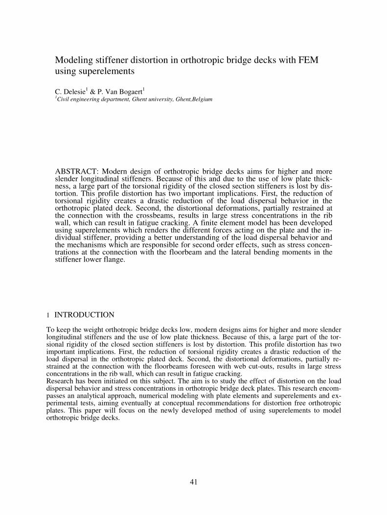
1 INTRODUCTION To keep the weight orthotropic bridge decks low, modern designs aims for higher and more slender longitudinal stiffeners and the use of low plate thickness. Because of this, a large part of the tor- sional rigidity of the closed section stiffeners is lost by distortion. This profile distortion has two important implications. First, the reduction of torsional rigidity creates a drastic reduction of the load dispersal in the orthotropic plated deck. Second, the distortional deformations, partially re- strained at the connection with the floorbeams foreseen with web cut-outs, results in large stress concentrations in the rib wall, which can result in fatigue cracking. Research has been initiated on this subject. The aim is to study the effect of distortion on the load dispersal behavior and stress concentrations in orthotropic bridge deck plates. This research encom- passes an analytical approach, numerical modeling with plate elements and superelements and ex- perimental tests, aiming eventually at conceptual recommendations for distortion free orthotropic plates. This paper will focus on the newly developed method of using superelements to model orthotropic bridge decks. ABSTRACT: Modern design of orthotropic bridge decks aims for higher and more slender longitudinal stiffeners. Because of this and due to the use of low plate thick- ness, a large part of the torsional rigidity of the closed section stiffeners is lost by dis- tortion. This profile distortion has two important implications. First, the reduction of torsional rigidity creates a drastic reduction of the load dispersal behavior in the orthotropic plated deck. Second, the distortional deformations, partially restrained at the connection with the crossbeams, results in large stress concentrations in the rib wall, which can result in fatigue cracking. A finite element model has been developed using superelements which renders the different forces acting on the plate and the in- dividual stiffener, providing a better understanding of the load dispersal behavior and the mechanisms which are responsible for second order effects, such as stress concen- trations at the connection with the floorbeam and the lateral bending moments in the stiffener lower flange. Modeling stiffener distortion in orthotropic bridge decks with FEM using superelements C. Delesie 1 & P. Van Bogaert 1 1 Civil engineering department, Ghent university, Ghent,Belgium 41
Transcript of 21 modeling stiffener distortion in orthotropic bridge ... · To keep the weight orthotropic bridge...
1 INTRODUCTION
To keep the weight orthotropic bridge decks low, modern designs aims for higher and more slender longitudinal stiffeners and the use of low plate thickness. Because of this, a large part of the tor-sional rigidity of the closed section stiffeners is lost by distortion. This profile distortion has two important implications. First, the reduction of torsional rigidity creates a drastic reduction of the load dispersal in the orthotropic plated deck. Second, the distortional deformations, partially re-strained at the connection with the floorbeams foreseen with web cut-outs, results in large stress concentrations in the rib wall, which can result in fatigue cracking. Research has been initiated on this subject. The aim is to study the effect of distortion on the load dispersal behavior and stress concentrations in orthotropic bridge deck plates. This research encom-passes an analytical approach, numerical modeling with plate elements and superelements and ex-perimental tests, aiming eventually at conceptual recommendations for distortion free orthotropic plates. This paper will focus on the newly developed method of using superelements to model orthotropic bridge decks.
ABSTRACT: Modern design of orthotropic bridge decks aims for higher and more slender longitudinal stiffeners. Because of this and due to the use of low plate thick-ness, a large part of the torsional rigidity of the closed section stiffeners is lost by dis-tortion. This profile distortion has two important implications. First, the reduction of torsional rigidity creates a drastic reduction of the load dispersal behavior in the orthotropic plated deck. Second, the distortional deformations, partially restrained at the connection with the crossbeams, results in large stress concentrations in the rib wall, which can result in fatigue cracking. A finite element model has been developed using superelements which renders the different forces acting on the plate and the in-dividual stiffener, providing a better understanding of the load dispersal behavior and the mechanisms which are responsible for second order effects, such as stress concen-trations at the connection with the floorbeam and the lateral bending moments in the stiffener lower flange.
Modeling stiffener distortion in orthotropic bridge decks with FEM using superelements
C. Delesie1 & P. Van Bogaert
1
1Civil engineering department, Ghent university, Ghent,Belgium
41
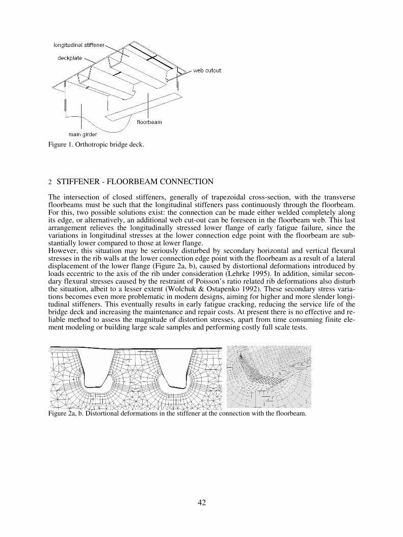
Figure 1. Orthotropic bridge deck.
2 STIFFENER - FLOORBEAM CONNECTION
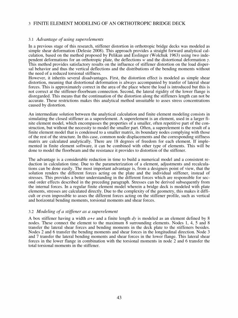
The intersection of closed stiffeners, generally of trapezoidal cross-section, with the transverse floorbeams must be such that the longitudinal stiffeners pass continuously through the floorbeam. For this, two possible solutions exist: the connection can be made either welded completely along its edge, or alternatively, an additional web cut-out can be foreseen in the floorbeam web. This last arrangement relieves the longitudinally stressed lower flange of early fatigue failure, since the variations in longitudinal stresses at the lower connection edge point with the floorbeam are sub-stantially lower compared to those at lower flange. However, this situation may be seriously disturbed by secondary horizontal and vertical flexural stresses in the rib walls at the lower connection edge point with the floorbeam as a result of a lateral displacement of the lower flange (Figure 2a, b), caused by distortional deformations introduced by loads eccentric to the axis of the rib under consideration (Lehrke 1995). In addition, similar secon-dary flexural stresses caused by the restraint of Poisson’s ratio related rib deformations also disturb the situation, albeit to a lesser extent (Wolchuk & Ostapenko 1992). These secondary stress varia-tions becomes even more problematic in modern designs, aiming for higher and more slender longi-tudinal stiffeners. This eventually results in early fatigue cracking, reducing the service life of the bridge deck and increasing the maintenance and repair costs. At present there is no effective and re-liable method to assess the magnitude of distortion stresses, apart from time consuming finite ele-ment modeling or building large scale samples and performing costly full scale tests.
Figure 2a, b. Distortional deformations in the stiffener at the connection with the floorbeam.
42
3 FINITE ELEMENT MODELING OF AN ORTHOTROPIC BRIDGE DECK
3.1 Advantage of using superelements
In a previous stage of this research, stiffener distortion in orthotropic bridge decks was modeled as simple shear deformation (Delesie 2008). This approach provides a straight forward analytical cal-culation, based on the method proposed by Pelikan and Esslinger (Wolchuk 1963) using two inde-pendent deformations for an orthotropic plate, the deflections w and the distortional deformation γ. This method provides satisfactory results on the influence of stiffener distortion on the load disper-sal behavior and thus the vertical deflections and the distributions of the bending moments without the need of a reduced torsional stiffness. However, it inherits several disadvantages. First, the distortion effect is modeled as simple shear distortion, meaning that distortional deformation is always accompanied by tranfer of lateral shear forces. This is approximately correct in the area of the place where the load is introduced but this is not correct at the stiffener-floorbeam connection. Second, the lateral rigidity of the lower flange is disregarded. This means that the continuation of the distortion along the stiffeners length can not be accurate. These restrictions makes this analytical method unsuitable to asses stress concentrations caused by distortion. An intermediate solution between the analytical calculation and finite element modeling consists in simulating the closed stiffener as a superelement. A superelement is an element, used in a larger fi-nite element model, which encompasses the properties of a smaller, often repetitive part of the con-struction, but without the necessity to model the smaller part. Often, a superelement is the result of a finite element model that is condensed to a smaller matrix, its boundary nodes complying with those of the rest of the structure. In this case, common node displacements and the corresponding stiffness matrix are calculated analytically. There are 18 degrees of freedom for each element. If imple-mented in finite element software, it can be combined with other type of elements. This will be done to model the floorbeam and the resistance it provides to distortion of the stiffener. The advantage is a considerable reduction in time to build a numerical model and a consistent re-duction in calculation time. Due to the parameterization of a element, adjustments and recalcula-tions can be done easily. The most important advantage is, from a designers point of view, that the solution renders the different forces acting on the plate and the individual stiffener, instead of stresses. This provides a better understanding in the different forces which are responsible for sec-ond order effects described in the preceding paragraph. Stresses can be derived subsequently from the internal forces. In a regular finite element model wherein a bridge deck is modeled with plate elements, stresses are calculated directly. Due to the complexity of the geometry, this makes it diffi-cult or even impossible to asses the different forces acting on the stiffener profile, such as vertical and horizontal bending moments, torsional moments and shear forces.
3.2 Modeling of a stiffener as a superelement
A box stiffener having a width a+e and a finite length dy is modeled as an element defined by 8 nodes. These connect the element to the maximum 8 surrounding elements. Nodes 1, 4, 5 and 8 transfer the lateral shear forces and bending moments in the deck plate to the stiffeners besides. Nodes 2 and 6 transfer the bending moments and shear forces in the longitudinal direction. Node 3 and 7 transfer the lateral bending moments and shear forces in the lower flange. This lateral shear forces in the lower flange in combination with the torsional moments in node 2 and 6 transfer the total torsional moments in the stiffener.
43
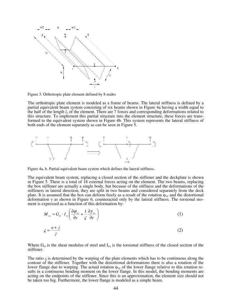
Figure 3. Orthotropic plate element defined by 8 nodes
The orthotropic plate element is modeled as a frame of beams. The lateral stiffness is defined by a partial equivalent beam system consisting of six beams shown in Figure 4a having a width equal to the half of the length ly of the element. There are 7 forces and corresponding deformations related to this structure. To implement this partial structure into the element structure, these forces are trans-formed to the equivalent system shown in Figure 4b. This system represents the lateral stiffness of both ends of the element separately as can be seen in Figure 5.
Figure 4a, b. Partial equivalent beam system which defines the lateral stiffness.
The equivalent beam system, replacing a closed section of the stiffener and the deckplate is shown in Figure 5. There is a total of 18 external forces acting on the element. The two beams, replacing the box stiffener are actually a single body, but because of the stiffness and the deformations of the stiffeners in lateral direction, they are split in two beams and considered separately from the deck plate. It is assumed that the box can deform freely as a result of the rotation φxz and the distortional deformation γ as shown in Figure 6, counteracted only by the lateral stiffness. The torsional mo-ment is expressed as a function of this deformation by:
∂
∂+
∂
∂⋅=
yyIGM xzxz
xzstxz
γ
ς
ϕ 1 (1)
j
ja +=ς (2)
Where Gst is the shear modulus of steel and Ixz is the torsional stiffness of the closed section of the stiffener. The ratio ς is determined by the warping of the plate elements which has to be continuous along the contour of the stiffener. Together with the distortional deformations there is also a rotation of the lower flange due to warping. The actual rotation φxy of the lower flange relative to this rotation re-sults in a continuous bending moment on the lower flange. In this model, the bending moments are acting on the endpoints of the stiffener. Since this is an approximation, the element size should not be taken too big. Furthermore, the lower flange is modeled as a simple beam.
44
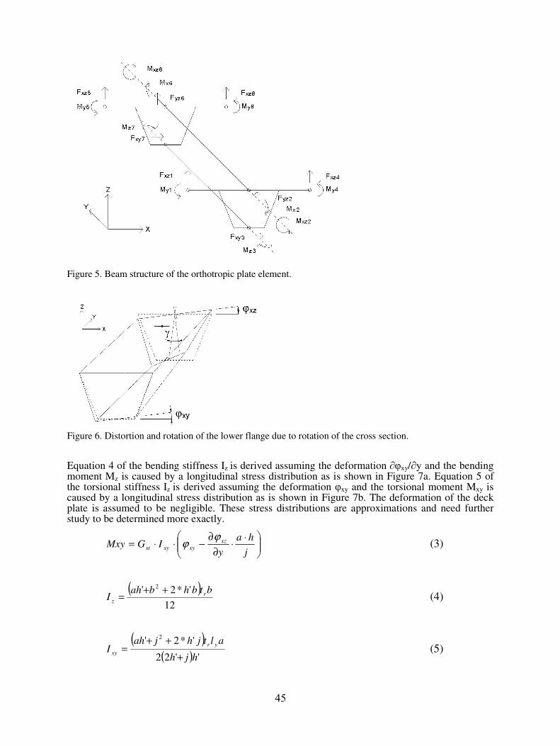
Figure 5. Beam structure of the orthotropic plate element.
Figure 6. Distortion and rotation of the lower flange due to rotation of the cross section. Equation 4 of the bending stiffness Iz is derived assuming the deformation ∂φxy/∂y and the bending moment Mz is caused by a longitudinal stress distribution as is shown in Figure 7a. Equation 5 of the torsional stiffness Iz is derived assuming the deformation φxy and the torsional moment Mxy is caused by a longitudinal stress distribution as is shown in Figure 7b. The deformation of the deck plate is assumed to be negligible. These stress distributions are approximations and need further study to be determined more exactly.
⋅⋅
∂
∂−⋅⋅=
j
ha
yIGMxy xz
xyxyst
ϕϕ (3)
( )12
'*2' 2btbhbah
I r
z
++= (4)
( )( ) ''22
'*2'2
hjh
altjhjahI
yr
xy+
++= (5)
45
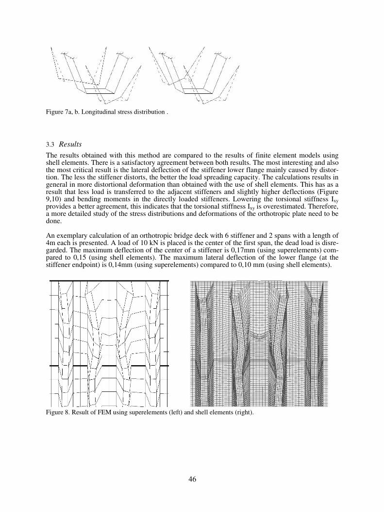
Figure 7a, b. Longitudinal stress distribution .
3.3 Results
The results obtained with this method are compared to the results of finite element models using shell elements. There is a satisfactory agreement between both results. The most interesting and also the most critical result is the lateral deflection of the stiffener lower flange mainly caused by distor-tion. The less the stiffener distorts, the better the load spreading capacity. The calculations results in general in more distortional deformation than obtained with the use of shell elements. This has as a result that less load is transferred to the adjacent stiffeners and slightly higher deflections (Figure 9,10) and bending moments in the directly loaded stiffeners. Lowering the torsional stiffness Ixy provides a better agreement, this indicates that the torsional stiffness Ixy is overestimated. Therefore, a more detailed study of the stress distributions and deformations of the orthotropic plate need to be done. An exemplary calculation of an orthotropic bridge deck with 6 stiffener and 2 spans with a length of 4m each is presented. A load of 10 kN is placed is the center of the first span, the dead load is disre-garded. The maximum deflection of the center of a stiffener is 0,17mm (using superelements) com-pared to 0,15 (using shell elements). The maximum lateral deflection of the lower flange (at the stiffener endpoint) is 0,14mm (using superelements) compared to 0,10 mm (using shell elements).
Figure 8. Result of FEM using superelements (left) and shell elements (right).
46
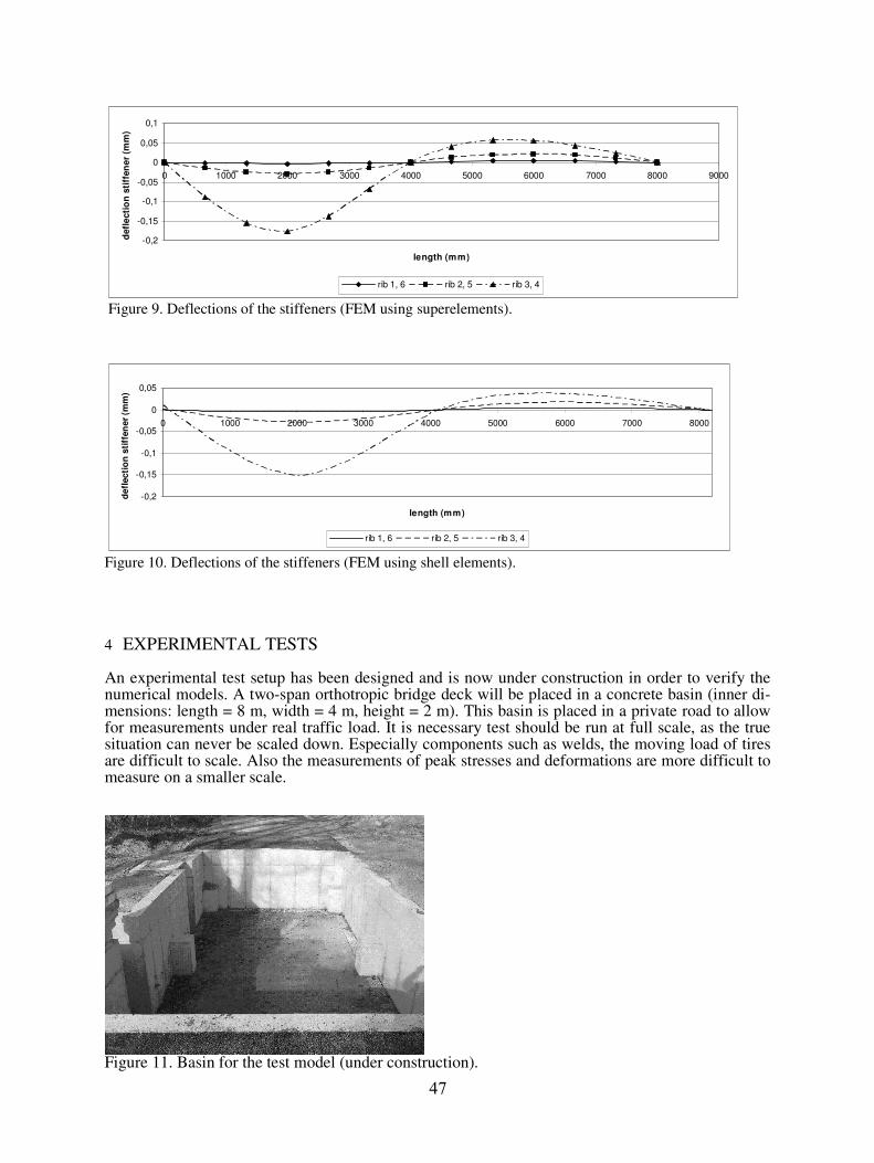
Figure 9. Deflections of the stiffeners (FEM using superelements).
Figure 10. Deflections of the stiffeners (FEM using shell elements).
4 EXPERIMENTAL TESTS
An experimental test setup has been designed and is now under construction in order to verify the numerical models. A two-span orthotropic bridge deck will be placed in a concrete basin (inner di-mensions: length = 8 m, width = 4 m, height = 2 m). This basin is placed in a private road to allow for measurements under real traffic load. It is necessary test should be run at full scale, as the true situation can never be scaled down. Especially components such as welds, the moving load of tires are difficult to scale. Also the measurements of peak stresses and deformations are more difficult to measure on a smaller scale.
Figure 11. Basin for the test model (under construction).
-0,2
-0,15
-0,1
-0,05
0
0,05
0,1
0 1000 2000 3000 4000 5000 6000 7000 8000 9000
length (mm)
defl
ecti
on
sti
ffen
er
(mm
)
rib 1, 6 rib 2, 5 rib 3, 4
-0,2
-0,15
-0,1
-0,05
0
0,05
0 1000 2000 3000 4000 5000 6000 7000 8000
length (mm)
defl
ecti
on
sti
ffen
er
(mm
)
rib 1, 6 rib 2, 5 rib 3, 4
47
Strains will be measured with resistive gauges with a short base, attached very close to the welds. The deformations and the position of the load can be measured in real time. The magnitude of the wheel loads can be measured in real time with a load sensor, providing a 2 dimensional image of the pressure of a tire. This device (40 cm x 80 cm) consists of an array (100 x 100) of small sensors with a range up to 10 N/mm².
5 CONCLUSION
During research concerning the effect of distortional deformation and it’s consequence on the load dispersal behavior in orthotropic bridge deck plates, a finite element program has been developed using superelements. This method renders the different forces acting on the plate and the individual stiffener, providing a better understanding of the load dispersal behavior and the mechanisms which are responsible for second order effects, such as stress concentrations at the connection with the floorbeam and the lateral bending moments in the stiffener lower flange. More research will be done at the stress distributions and deformations in the stiffener because its correct modeling is critical to the distortional behavior of the orthotropic deck. The model will also be expanded with the implementing of flexural floorbeams and the effect of the lateral resistance a floorbeam with copeholes provides to the lateral deflection of the stiffener lower flange. This effect is related to stress concentrations in the rib wall which eventually can results in fatigue cracking. Calculations will be validated by tests on a full scale test sample.
REFERENCES
Delesie C et al. 2008, The effect of stiffener distortion of orthotropic bridge decks on load dispersal behavior and stress concentrations, The 2
nd International Orthotropic Bridge Conference, ASCE, August 2008, Sacra-
mento, USA Lehrke, H 1995. Measurements and interpretation of dynamic loads on bridges, fourth phase, fatigue design of orthotropic steel decks of road bridges, Contribution to common report, Brussels Wolchuk, R. 1963. Design Manual for Orthotropic Steel Plate Deck Bridges, AISC Wolchuk, R., and Ostapenko A. 1992. Secondary stresses in closed orthotropic deck ribs at floor beams, Journal of Structural Engineering, 118(2), 582-595
48