
21 Data Formats
10
09-04-2015 1 • The SLC (StereoLithograpy Contour) file format was developed by 3D Systems, USA. It addresses a number of problems associated with STL files like size of the files, problems related to facet generation etc. • SLC tries to solve the problems by taking two-dimensional slices directly from the CAD model instead of using an intermediate tessellated STL model. • These slices eliminate the facets associated with STL files because they approximate the contours of the actual geometry. • The SLC file format consists of successive cross-sections taken in ascending Z interval in which solid material is represented by interior and exterior polylines.
-
Upload
dharminder-singh -
Category
Documents
-
view
17 -
download
1
description
in rpp
Transcript of 21 Data Formats
09-04-2015
1
• The SLC (StereoLithograpy Contour) file format was developed by 3D
Systems, USA. It addresses a number of problems associated with
STL files like size of the files, problems related to facet generation
etc.
• SLC tries to solve the problems by taking two-dimensional slices
directly from the CAD model instead of using an intermediate
tessellated STL model.
• These slices eliminate the facets associated with STL files because
they approximate the contours of the actual geometry.
• The SLC file format consists of successive cross-sections taken in
ascending Z interval in which solid material is represented by
interior and exterior polylines.
09-04-2015
2
• SLC data can be generated from various sources, either by
conversion from CAD solid or surface models, or more directly from
systems which produce data arranged in layers like CT scanners.
• However three problems may arise from the use of SLC format.
• Firstly, in slicing a CAD model, it is not always necessarily accurate as
the contours of each slice are still approximations of the geometry.
• Secondly, slicing in this manner requires much more complicated
calculations, which are still time consuming, when compared to the
relatively straight-forward STL files.
• Thirdly, a feature of CAD model which falls between two slices, but is
just under the tolerances set for inclusion on either of the adjacent
slices may simply disappear.
• Segment: A segment is a straight line connecting two X/Y vertice
points.
• Polyline: A polyline is an ordered list of X/Y vertices connected
continuously by each successive line segment. The polyline must be
closed whereby the last point must equal the first point in the
vertice list.
• Contour Boundary: A boundary is a closed polyline representing
interior or exterior solid material. An exterior boundary has its
polyline list in the counter-clockwise order. The solid material is
inside the polyline. An interior boundary has its polyline list in the
clockwise order and solid material is outside the polyline.
• Contour Layer: A contour layer is a list of exterior and interior
boundaries representing the solid material at a specified Z cross
section of the CAD model. The cross section slice is taken parallel to
the X/Y plane and has a specified layer thickness.

09-04-2015
3
• The CLI (Common Layer Interface) format is developed in a Brite
Euram project with the support of major European car
manufacturers.
• The CLI format is meant to be vendor-independent format for layer
by layer manufacturing technologies.
• In this format, a part is built by a succession of layer descriptions.
The CLI file can be in binary or ASCII format.
• The geometry part of the file is organised in layers in the ascending
order. Every layer is started by a layer command giving the height of
the layer.
• The layer consists of series of geometric commands. The CLI format
has two kinds of entities. First is the polyline. The polylines are
closed, which means that they have a unique sense, either clockwise
or anticlockwise.
• This directional sense is used in CLI format to state whether a
polyline is on the outside of the part or surrounding a hole in the
part. Counter-clockwise polylines surround the part, whereas
clockwise polylines surround holes. This allows correct directions for
the beam offset.
• The other part is the hatching to distinguish between the inside and
outside of the part. As this information is already present in the
direction of the polylines and hatching takes up considerable file
space, hatches have not been included into output files.
09-04-2015
4
• Since the CLI format only supports polyline entities, it is simpler
format.
• The slicing step can be avoided in some applications.
• The error in the layer information is much easier to be corrected
than that in the 3D information.
• Automated recovery procedures can be used and if required, editing
is not difficult.
• The CLI format only has the capability of producing polylines of the
outline of the slice.
• Although the real outline of the part is obtained, by reducing the
curve to segments of straight lines, the advantage over the STL file
format is lost.
• The RPI (Rapid Prototyping Interface) format is designed by
Renesselaer Design Research Center. It can be derived from
currently accepted STL format data.
• The RPI data is capable of representing facet solids, but it also
includes additional information about the facet topology.
• Topological information is maintained by representing each facet
solid entity with indexed list of vertices, edges and faces.
• Instead of explicitly specifying the vertex coordinates for each facet,
a facet can refer to them by index number. This contributes to the
goal of overall redundant information reduction.
• The format is developed in ASCII to facilitate cross platform data
exchange and debugging.

09-04-2015
5
• A RPI format file is composed of the collection of entities, each of
which internally defines the data it contains.
• Each entity is composed of an entity name, a record count, a schema
definition, schema termination symbol and the corresponding data.
• The data is logically subdivided into records which are made up of
fields. Each record corresponds to one variable type in the type
definition.
• Each entity conforms to the syntax which is defined by the syntax
diagram given below.
• Topological information is added to the RPI format. As a result
flexibility is achieved. It allows the user to balance storage and
processing cost.
• Redundancy in the STL is removed and file size is compacted.
• Format extensibility is made possible by interleaving the format
schema with data.
• Representation of CSG primitives is provided, as capabilities to
represent multiple instances of both facets and CSG solids.
• An interpreter which processes a format as flexible and extensible as
the RPI format is more complex than that for the STL format.
• Surface patches suitable for solid approximation cannot be
identified in the RPI format.
09-04-2015
6
• The LEAF (Layer Exchange ASCII Format) was developed by Helsinki
University of Technology.
• Concepts from object oriented paradigm are borrowed. At the top
level, there is an object called LMT (Layer Manufacture Technology)
file that can contain parts which in turn are composed of other parts
or by layers.
• Ultimately, layers are composed of 2D primitives and currently the
only once which are planned for implementation are polylines.
• In LEAF, the properties support structure and open can also be
attached to layer or even polyline objects allowing the sender to
represent the original model and support structures as one single
part.
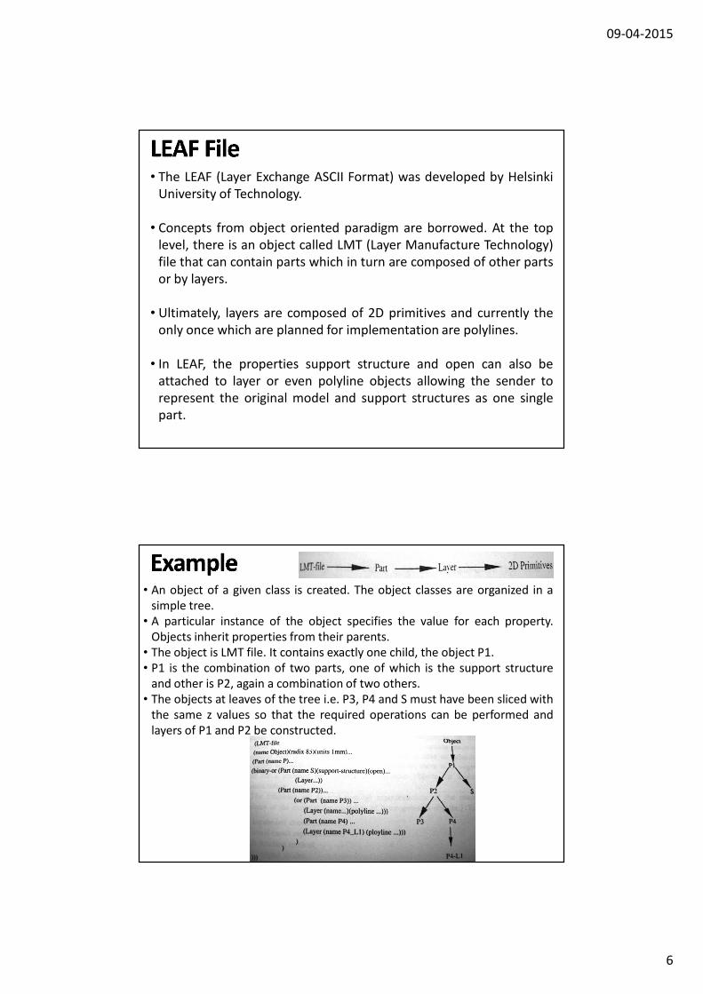
• An object of a given class is created. The object classes are organized in a
simple tree.
• A particular instance of the object specifies the value for each property.
Objects inherit properties from their parents.
• The object is LMT file. It contains exactly one child, the object P1.
• P1 is the combination of two parts, one of which is the support structure
and other is P2, again a combination of two others.
• The objects at leaves of the tree i.e. P3, P4 and S must have been sliced with
the same z values so that the required operations can be performed and
layers of P1 and P2 be constructed.

09-04-2015
7
• It is easy to implement and use. It is not ambiguous.
• It allows for data compression and for a human readable
representation.
• It is machine independent and LMT process independent.
• Slices of CSG models can be represented almost directly in LEAF.
• The part representing the support structures can be easily separated
from the original part.
• The new interpreter is needed for connecting the rapid prototyping
systems.
• The structure of the format is more complicated than that of the STL
format.
• The STL format cannot be changed into this format.
• IGES (Initial Graphics Exchange Specification) is a standard used to
exchange graphics information between commercial CAD systems. It
was set up as an American National Standard in 1981.
• The IGES can precisely represent a CAD model. It includes not only
the geometrical information but also topological information.
• In the IGES, surface modelling, CSG and Boundary representation
are introduced. The ways of representing the regularized operations
for union, intersection and difference have also been defined.
• The advantages of IGES standard are its wide adoption and
comprehensive coverage. Since IGES was set up as American
National Standard, virtually every commercial CAD/CAM system has
adopted IGES implementations. Furthermore, it provides the entities
of points, lines, arc, splines, NURBS and solid elements. Therefore it
can precisely represent CAD model

09-04-2015
8
• Because IGES is the standard format to exchange data between CAD
systems, it also includes very much redundant information that is
not needed for the rapid prototyping systems.
• The algorithms for slicing an IGES file are more complex than the
algorithms slicing the STL file.
• The support structures needed in RP systems such as SLA cannot be
created according to the IGES format.
• HP/GL (Hewlett-Packard Graphics Language) is a standard data
format for graphics plotters.
• Data types are two-dimensional including lines, circle, splines, texts
etc.
• This approach as seen from designer’s point of view would be to
automate a slicing routine which generates a section slice, invoke
the plotter routine to produce output file and then loop back to
repeat the process.
• The main advantages of HP/GL format are that a lot of commercial
CAD systems have the interface to output the HP/GL format and it is
2D geometry data format which does not need be sliced.
• Two main distinct disadvantages of HP/GL format are that because
HP/GL is a 2D data format, the files will not be appended, leaving
hundreds of small files needing to be given logical names and then
transferred. All the support structures required must be generated
in CAD system and sliced in the same way.

09-04-2015
9
• CT (Computerized Tomography) scan data is a particular approach
for medical imaging. This is not an standardized data format. The
formats are unique and proprietary.
• The scan generates data as a grid of 3D points, where each point has
a varying shade of gray indicating the density of the body tissue
found at a particular point. The CT data essentially consists of raster
images of the physical objects being scanned.
• The data from CT scans are used to build skull, knee and other bone
models on RP systems. Reproductions are also used to generate
implants which are installed in patients. It is also used to produce
models of human temporal bones.
• There are 3 approaches to making models out of CT scan
information. They are (1) through CAD model (2) STL interfacing (3)
by direct interfacing
• The main advantage of using CT data as an interface of Rapid
Prototyping is that it is possible to produce structures of human
body by RP systems.
• It is very difficult to deal with image data as compared to STL data.
• A special interpreter is required to process the CT data.

09-04-2015
10