209 MDE Lecture
35
1 Biomedical Equipment Troubleshooting 1 st Semester 1428-1429
-
Upload
nonoaly2006 -
Category
Documents
-
view
231 -
download
0
Transcript of 209 MDE Lecture
8/8/2019 209 MDE Lecture
http://slidepdf.com/reader/full/209-mde-lecture 1/35
1
Biomedical EquipmentTroubleshooting
1st Semester 1428-1429
8/8/2019 209 MDE Lecture
http://slidepdf.com/reader/full/209-mde-lecture 2/35
2
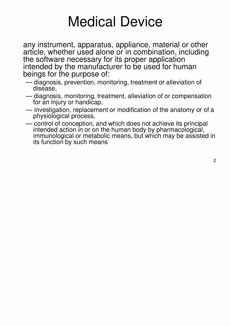
Medical Device
any instrument, apparatus, appliance, material or otherarticle, whether used alone or in combination, including
the software necessary for its proper applicationintended by the manufacturer to be used for humanbeings for the purpose of: — diagnosis, prevention, monitoring, treatment or alleviation of
disease, — diagnosis, monitoring, treatment, alleviation of or compensationfor an injury or handicap,
— investigation, replacement or modification of the anatomy or of aphysiological process,
— control of conception, and which does not achieve its principalintended action in or on the human body by pharmacological,immunological or metabolic means, but which may be assisted inits function by such means
8/8/2019 209 MDE Lecture
http://slidepdf.com/reader/full/209-mde-lecture 3/35
3
Troubleshooting
• (trub´&l-shoot´´) (v.) To isolate the source of a
problem and fix it, typically through a process ofelimination whereby possible sources of theproblem are investigated and eliminatedbeginning with the most obvious or easiestproblem to fix.
• In the case of computer systems, the termtroubleshoot is usually used when the problem issuspected to be hardware-related. If the problemis known to be in software, the term debug ismore commonly used.
8/8/2019 209 MDE Lecture
http://slidepdf.com/reader/full/209-mde-lecture 4/35
4
How can a medical device be
Troubleshooted?• Be able to read and understand the
Service’s and User’s Manuals• Be able to use biomedical hand tools.
• Be able to use multimeter (Voltmeter,Ammeter, Ohmmeter..)
• Be able to use Oscilloscope
8/8/2019 209 MDE Lecture
http://slidepdf.com/reader/full/209-mde-lecture 5/35
5
Service’s and User’s Manuals
• Service’s Manual provides useful
information to Qualified Service Personal(QSP) to understand, troubleshoot,service, maintain and repair a medicalequipment (device)
• User’s Manual helps the medical staff to
operate a medical device
8/8/2019 209 MDE Lecture
http://slidepdf.com/reader/full/209-mde-lecture 6/35
6
Sections of Service’s Manual
• General
• Maintenance• Troubleshooting
• System Test• Board description
• Disassembly and Assembly
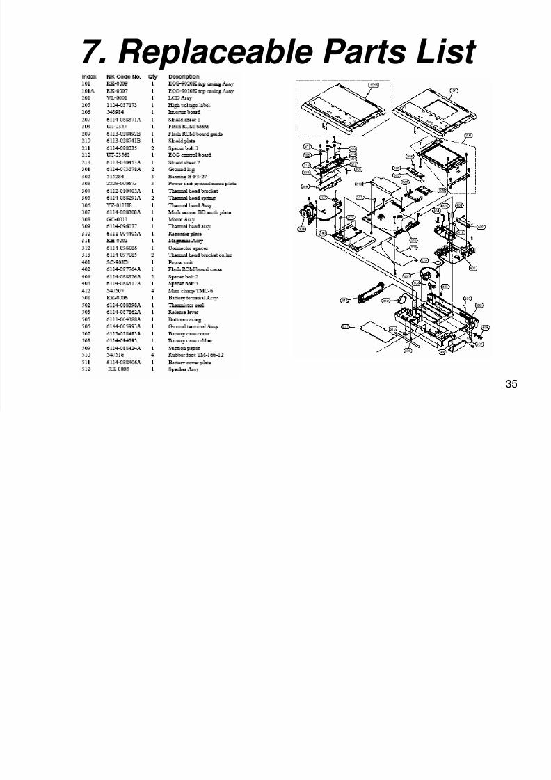
• Replaceable Parts List
• How to reach the manufacturer
8/8/2019 209 MDE Lecture
http://slidepdf.com/reader/full/209-mde-lecture 7/35
7
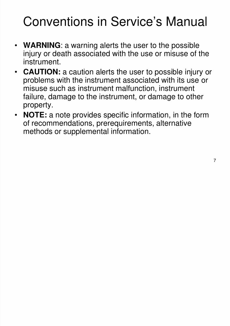
Conventions in Service’s Manual
• WARNING: a warning alerts the user to the possibleinjury or death associated with the use or misuse of the
instrument.• CAUTION: a caution alerts the user to possible injury or
problems with the instrument associated with its use or
misuse such as instrument malfunction, instrumentfailure, damage to the instrument, or damage to otherproperty.
• NOTE: a note provides specific information, in the formof recommendations, prerequirements, alternativemethods or supplemental information.
8/8/2019 209 MDE Lecture
http://slidepdf.com/reader/full/209-mde-lecture 8/35
8
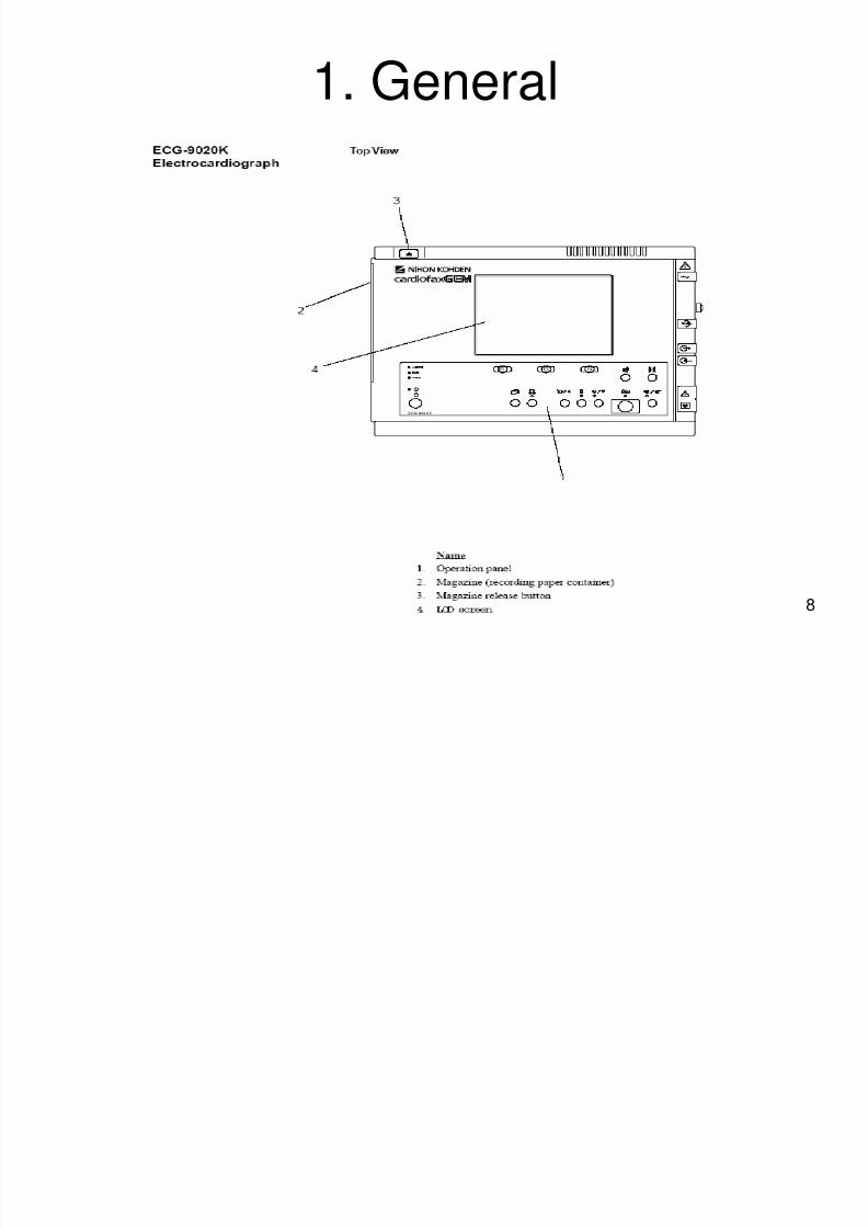
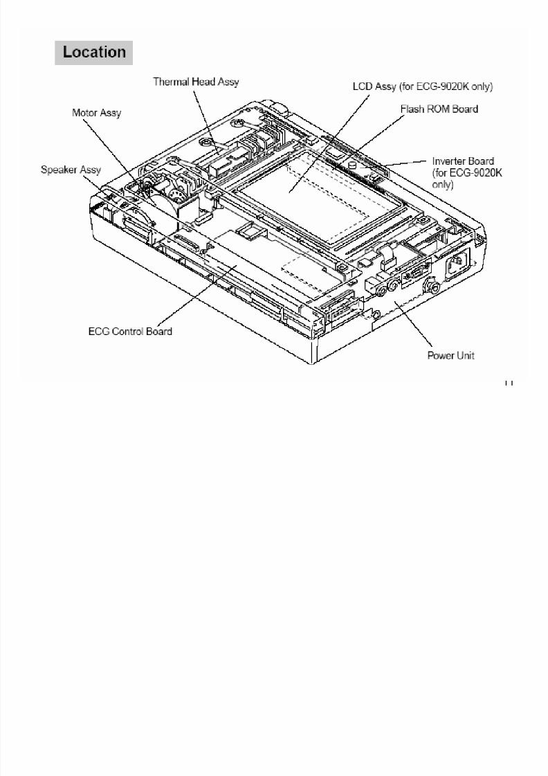
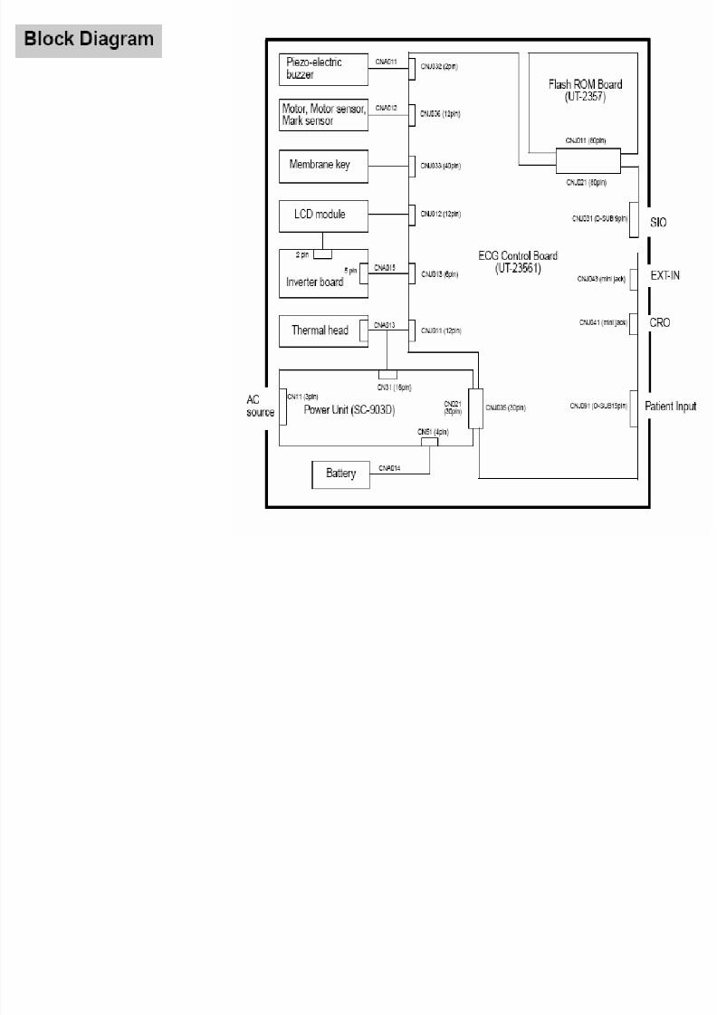
1. General
8/8/2019 209 MDE Lecture
http://slidepdf.com/reader/full/209-mde-lecture 9/35
9
8/8/2019 209 MDE Lecture
http://slidepdf.com/reader/full/209-mde-lecture 10/35
10
8/8/2019 209 MDE Lecture
http://slidepdf.com/reader/full/209-mde-lecture 11/35
11
8/8/2019 209 MDE Lecture
http://slidepdf.com/reader/full/209-mde-lecture 12/35
12
8/8/2019 209 MDE Lecture
http://slidepdf.com/reader/full/209-mde-lecture 13/35
13
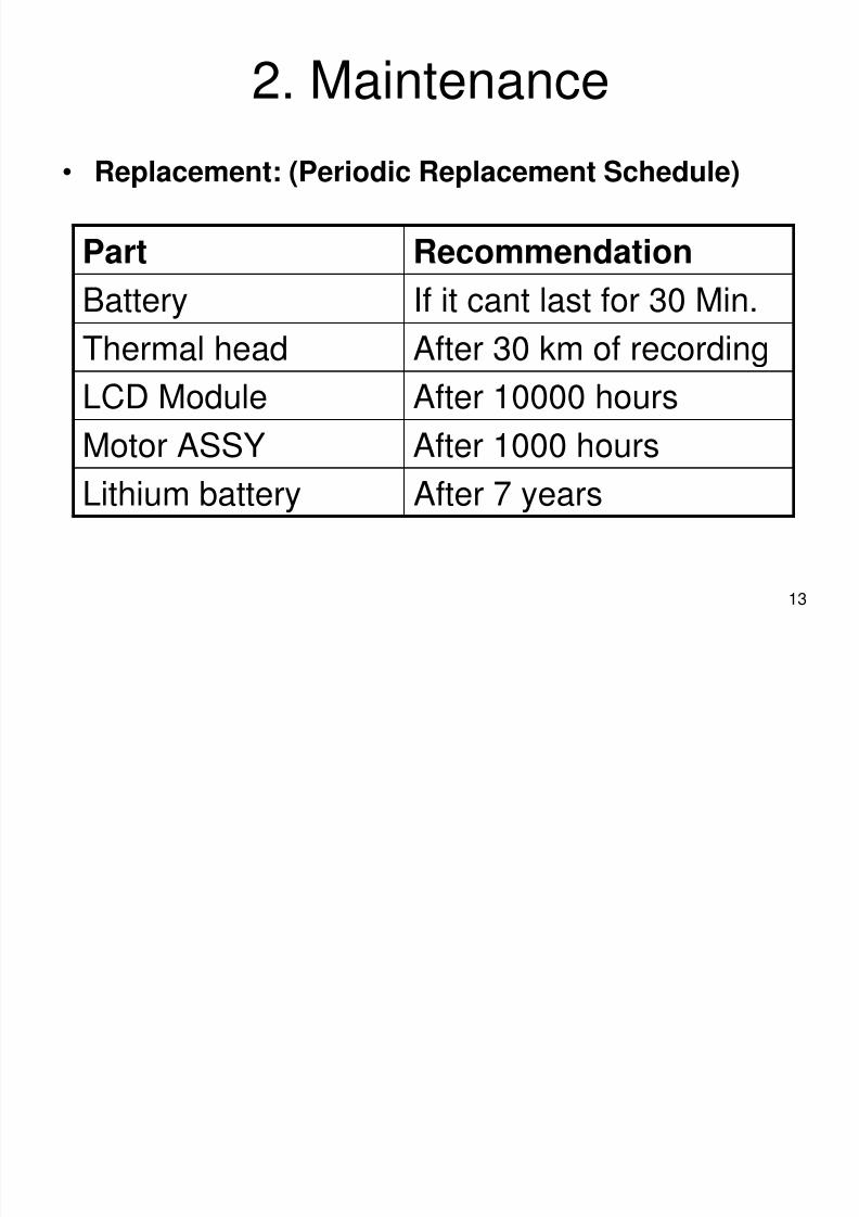
2. Maintenance
• Replacement: (Periodic Replacement Schedule)
Part Recommendation
Battery If it cant last for 30 Min.
Thermal head After 30 km of recording
LCD Module After 10000 hours
Motor ASSY After 1000 hoursLithium battery After 7 years
8/8/2019 209 MDE Lecture
http://slidepdf.com/reader/full/209-mde-lecture 14/35
14
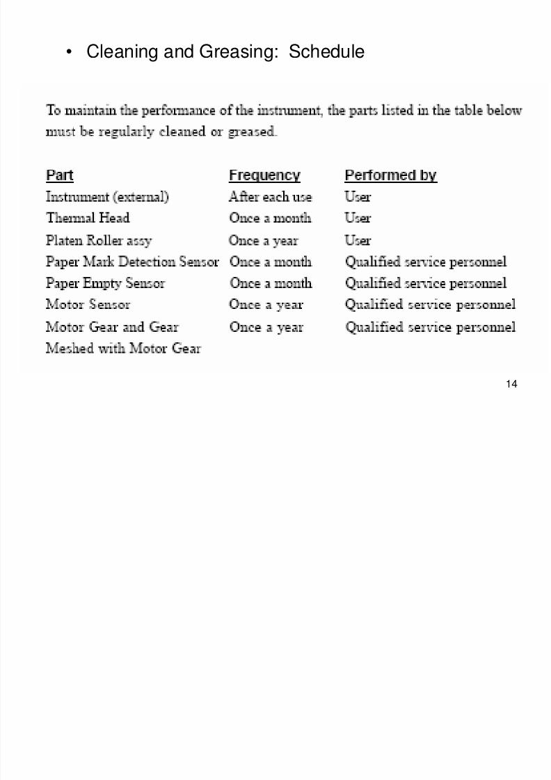
• Cleaning and Greasing: Schedule
8/8/2019 209 MDE Lecture
http://slidepdf.com/reader/full/209-mde-lecture 15/35
15
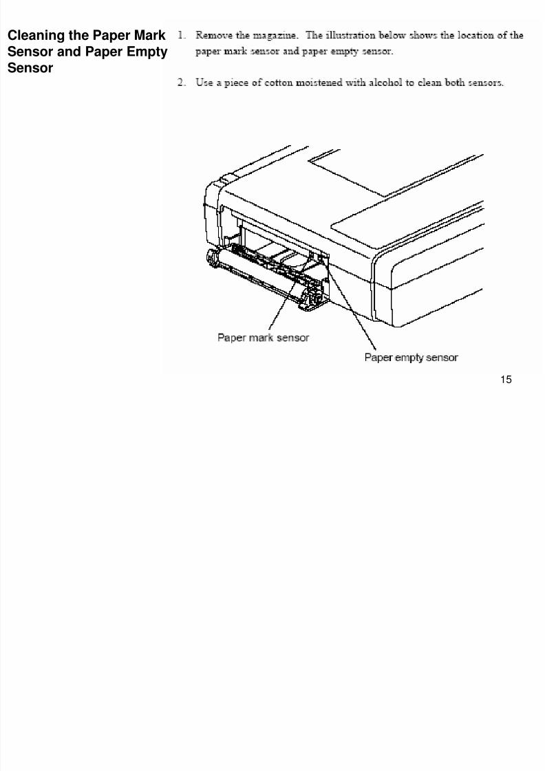
Cleaning the Paper MarkSensor and Paper Empty
Sensor
8/8/2019 209 MDE Lecture
http://slidepdf.com/reader/full/209-mde-lecture 16/35
16
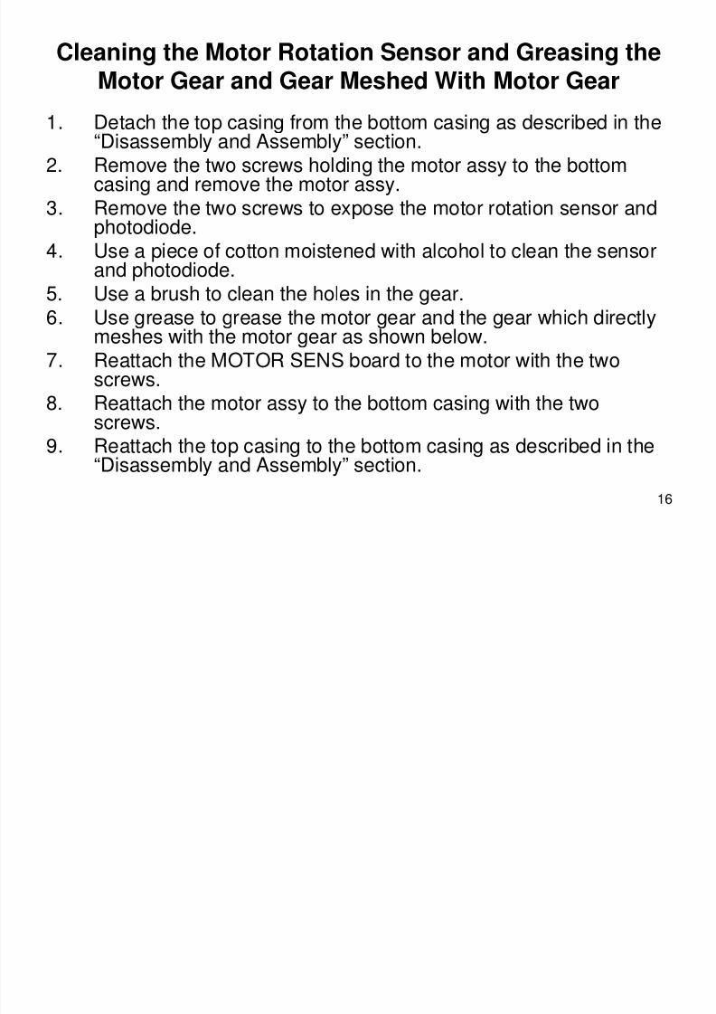
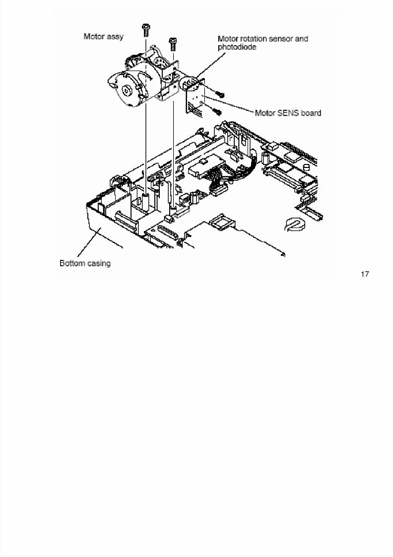
Cleaning the Motor Rotation Sensor and Greasing theMotor Gear and Gear Meshed With Motor Gear
1. Detach the top casing from the bottom casing as described in the“Disassembly and Assembly” section.
2. Remove the two screws holding the motor assy to the bottom
casing and remove the motor assy.3. Remove the two screws to expose the motor rotation sensor andphotodiode.
4. Use a piece of cotton moistened with alcohol to clean the sensorand photodiode.
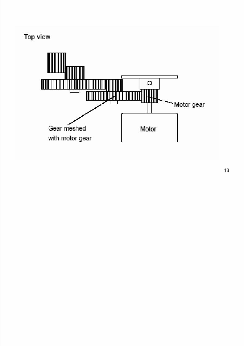
5. Use a brush to clean the holes in the gear.6. Use grease to grease the motor gear and the gear which directly
meshes with the motor gear as shown below.7. Reattach the MOTOR SENS board to the motor with the two
screws.8. Reattach the motor assy to the bottom casing with the two
screws.9. Reattach the top casing to the bottom casing as described in the
“Disassembly and Assembly” section.
8/8/2019 209 MDE Lecture
http://slidepdf.com/reader/full/209-mde-lecture 17/35
17
8/8/2019 209 MDE Lecture
http://slidepdf.com/reader/full/209-mde-lecture 18/35
18
8/8/2019 209 MDE Lecture
http://slidepdf.com/reader/full/209-mde-lecture 19/35
19
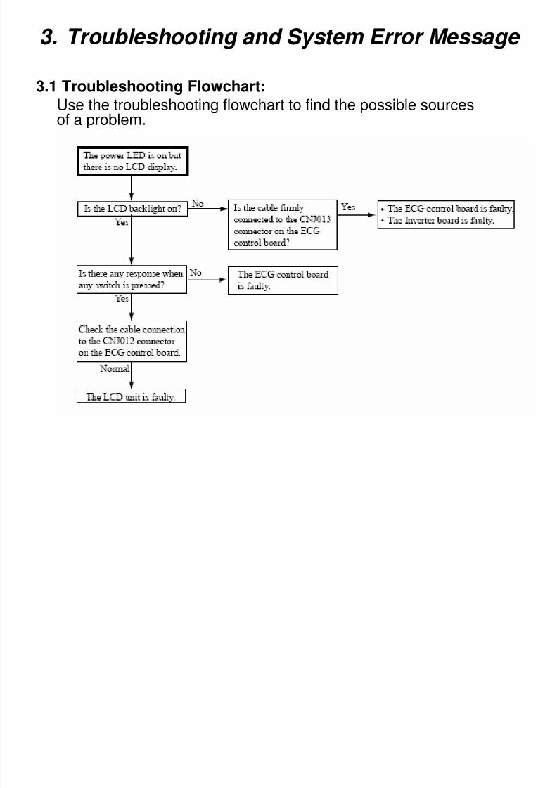
3. Troubleshooting and System Error Message
3.1 Troubleshooting Flowchart:Use the troubleshooting flowchart to find the possible sourcesof a problem.
8/8/2019 209 MDE Lecture
http://slidepdf.com/reader/full/209-mde-lecture 20/35
20
3.2 Troubleshooting TableUse the troubleshooting table to locate, identify and solve aproblem in the instrument. The problems are divided intogeneral operation and recording Each category has its own
troubleshooting table for fast and easy troubleshooting.
How to use the troubleshooting table
1. Determine which troubleshooting table to use.2. In the “Problem” column find the trouble item that matches the
problem.
3. Do the action recommended in the “Corrective Action” column.
4. If the problem is not solved, do the action for the next possiblecause or criteria.
5. If none of the actions solve the problem, contact dealer
8/8/2019 209 MDE Lecture
http://slidepdf.com/reader/full/209-mde-lecture 21/35
21
3.3 System Error Message
During power-up and operation the instrument
continuously checks itself for system failure. If afailure is detected, system information and errorhistory are printed on the recording paper and all
operations are stopped. System information anderror history are also displayed or printed due totransient noise. After printing the system
information and error history, the power of theinstrument is automatically turned off.
8/8/2019 209 MDE Lecture
http://slidepdf.com/reader/full/209-mde-lecture 22/35
22
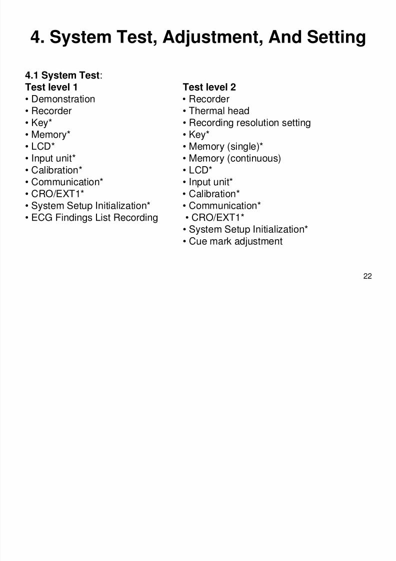
4. System Test, Adjustment, And Setting
4.1 System Test:Test level 1 Test level 2• Demonstration • Recorder• Recorder • Thermal head• Key* • Recording resolution setting• Memory* • Key*• LCD* • Memory (single)*
• Input unit* • Memory (continuous)• Calibration* • LCD*• Communication* • Input unit*• CRO/EXT1* • Calibration*
• System Setup Initialization* • Communication*• ECG Findings List Recording • CRO/EXT1*• System Setup Initialization*
• Cue mark adjustment
8/8/2019 209 MDE Lecture
http://slidepdf.com/reader/full/209-mde-lecture 23/35
23
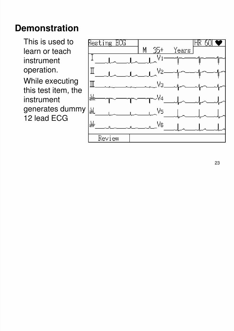
DemonstrationThis is used to
learn or teach
instrumentoperation.
While executing
this test item, theinstrumentgenerates dummy12 lead ECG
8/8/2019 209 MDE Lecture
http://slidepdf.com/reader/full/209-mde-lecture 24/35
24
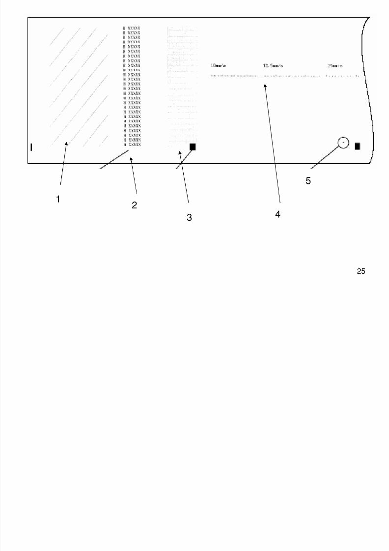
Recorder
This is used to check the condition of therecorder by printing test patterns. Therecording test patterns consist of the followingand are printed in the following order:
1. Diagonal lines (Check Thermal Head )
2. Characters H and X (Check Thermal Head )
3. Grid (Check ECG control B .)
4. Paper speed scales (10, 12.5, 25 and 50 mm/s)(Check Motor, Gear, Sensor )
5. Paper mark detection (Check Sensor )
8/8/2019 209 MDE Lecture
http://slidepdf.com/reader/full/209-mde-lecture 25/35
25
12
3 4
5
8/8/2019 209 MDE Lecture
http://slidepdf.com/reader/full/209-mde-lecture 26/35
26
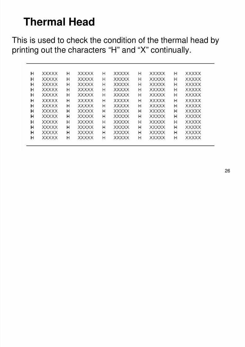
Thermal Head
This is used to check the condition of the thermal head byprinting out the characters “H” and “X” continually.
8/8/2019 209 MDE Lecture
http://slidepdf.com/reader/full/209-mde-lecture 27/35
27
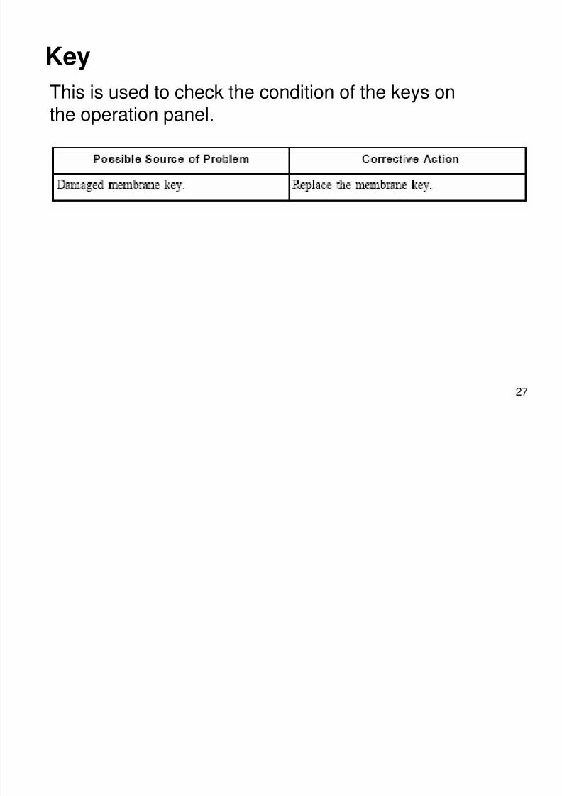
Key
This is used to check the condition of the keys onthe operation panel.
8/8/2019 209 MDE Lecture
http://slidepdf.com/reader/full/209-mde-lecture 28/35
28
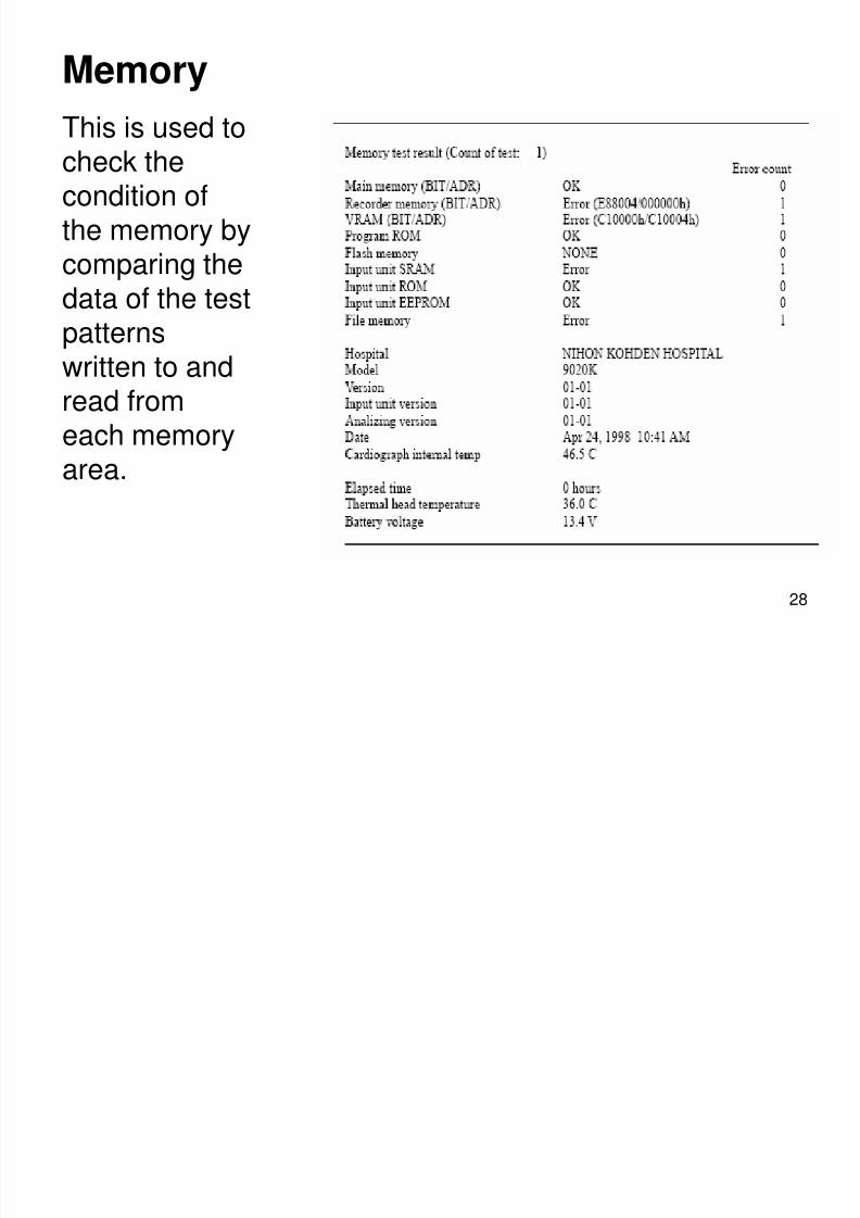
Memory
This is used tocheck thecondition of
the memory bycomparing thedata of the test
patternswritten to andread fromeach memoryarea.
LCD
8/8/2019 209 MDE Lecture
http://slidepdf.com/reader/full/209-mde-lecture 29/35
29
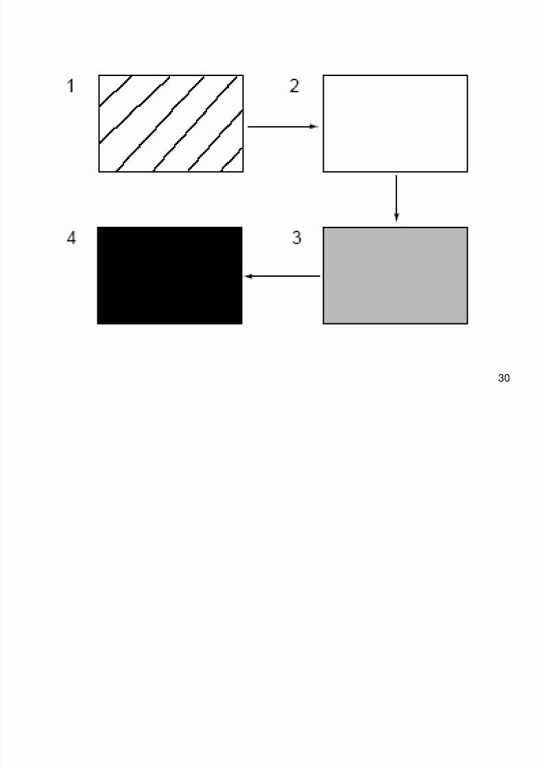
LCD
The LCD displays the following four types of testpatterns every two seconds in the following order:
1. Diagonal lines are displayed.2. Entire LCD lights up.3. LCD is completely dark but backlight lights.4. Backlight does not light.
8/8/2019 209 MDE Lecture
http://slidepdf.com/reader/full/209-mde-lecture 30/35
30
8/8/2019 209 MDE Lecture
http://slidepdf.com/reader/full/209-mde-lecture 31/35
31
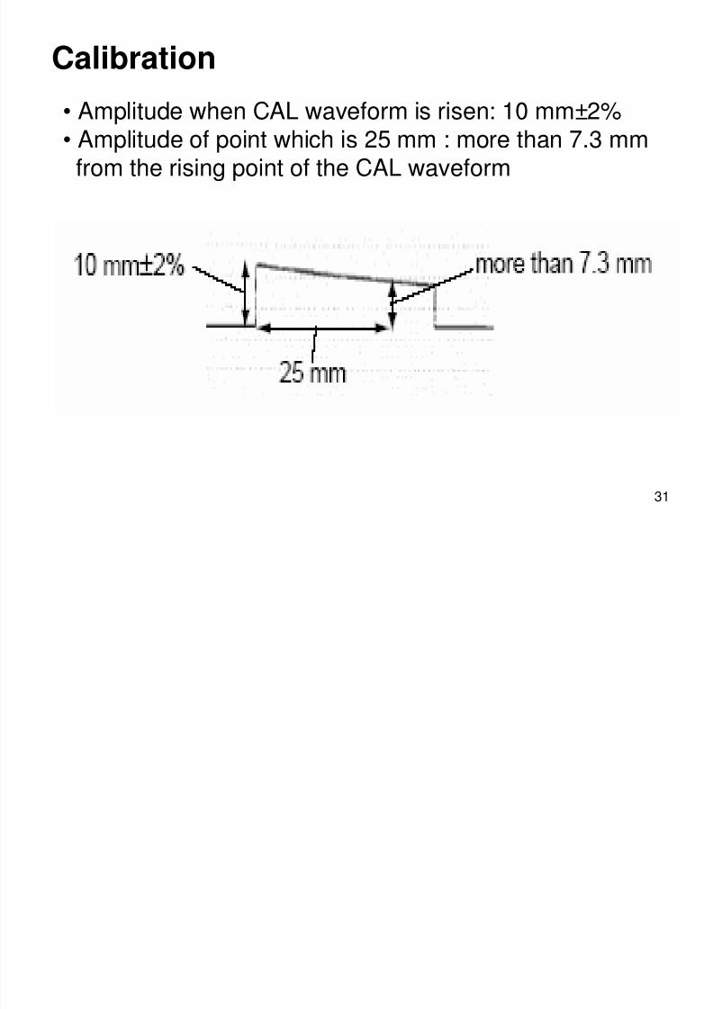
Calibration
• Amplitude when CAL waveform is risen: 10 mm±2%• Amplitude of point which is 25 mm : more than 7.3 mmfrom the rising point of the CAL waveform
8/8/2019 209 MDE Lecture
http://slidepdf.com/reader/full/209-mde-lecture 32/35
32
5. Board/Unit Description
• Power Unit
The Power unit consists of the power source, batterycharging and control circuits. The Power unit uses theswitching regulation method to produce the powerrequired for the instrument.
• Flash ROM Board
The Flash ROM board has a 2 MB flash ROM for writing
the control program, analysis program, Japanese fontand English font to the ROM. Also, there is a space formounting an EEPROM.
8/8/2019 209 MDE Lecture
http://slidepdf.com/reader/full/209-mde-lecture 33/35
8/8/2019 209 MDE Lecture
http://slidepdf.com/reader/full/209-mde-lecture 34/35
34
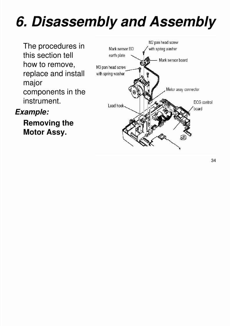
6. Disassembly and Assembly
The procedures inthis section tell
how to remove,replace and installmajor
components in theinstrument.
Example:
Removing theMotor Assy.
8/8/2019 209 MDE Lecture
http://slidepdf.com/reader/full/209-mde-lecture 35/35