2080-qr002_-en-p
180
. 1 Micro800™ and Connected Components Workbench™ Application Guide
-
Upload
claudia-katherine-pacherrez-vinces -
Category
Documents
-
view
108 -
download
25
Transcript of 2080-qr002_-en-p

.
1
Micro800™ and Connected Components Workbench™
Application Guide

2
Table of Contents
Chapter 1: Flash Updating Micro800 Firmware
Chapter 2: Importing and Exporting User-Defined Function Blocks
Chapter 3: Creating a New Function Block Program
Chapter 4: Creating a New Structured Text Program
Chapter 5: Using CCW with PanelView Component
Chapter 6: Using CCW with PowerFlex Drives
Chapter 7: Using CCW with Temperature Controllers
3
Requirements Hardware RequirementsU: Micro810, 2080-LC10-12QWB. Micro830, 2080-LC30-16QWB Micro830 Plug-In, 2080-SERIALISOL
Standard USB Cable Software RequirementsU: Connected Components Workbench (CCW), Release 1.0
RSLinx, v 2.57
4
Chapter 1 –
Flash Updating Micro800 Firmware

5
Flash Updating Micro800 Firmware
This chapter will show you how to flash update the firmware in a Micro800 controller using ControlFLASH. ControlFLASH is installed or updated with the latest Micro800 firmware when Connected Components Workbench software is installed on your computer.
1. First verify successful RSLinx Classic communications with your Micro800 controller via USB using
RSWho (Micro810 12-pt. uses the 12PtM810_xxxxx driver and the Micro830 uses the AB_VBP-x
driver).
2. Start ControlFLASH and click Next:

6
3. Select the catalog number of the Micro800 that you are going to update and click Next:

7
4. Select the controller in the browse window and click OK:
5. If you get the following screen (Micro810 only), leave the Slot Number at 0 and click OK:

8
6. Click Next to continue, verify the revisions, then click Finish and Yes to initiate the update:

9
7. The next screen should show the download progress:
8. If you get the following error message instead, check to see if the controller is faulted or in Run mode.
If so, clear the fault or switch to Program mode, click OK and try again.
9. When the flash update is complete, you should get a status screen similar to the following. Click OK
to complete:

10
Chapter 2 –
Importing and Exporting User-Defined Function Blocks

11
Importing and Exporting User-Defined Function Blocks
This chapter will show you how to create and export a SIM_FB User Defined Function Block (UDFB) so that it can be imported into other projects.
1. Create a new Micro830 project.
2. Under Project Organizer, right click on Function Blocks, select Add then New ST :Structured Text:

12
3. Right click on UntitledST, select Rename and type in “SIM_FB”:
4. Double click on SIM_FB and type in the following:
13
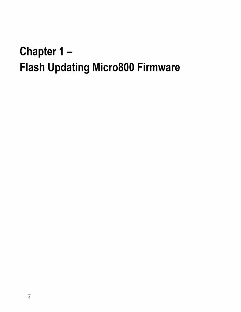
5. Below SIM_FB, double click on Local Variables and enter in the following:
6. Right click on SIM_FB and select Build:
If you get any Build errors, correct the errors and Build again until you succeed with no errors.
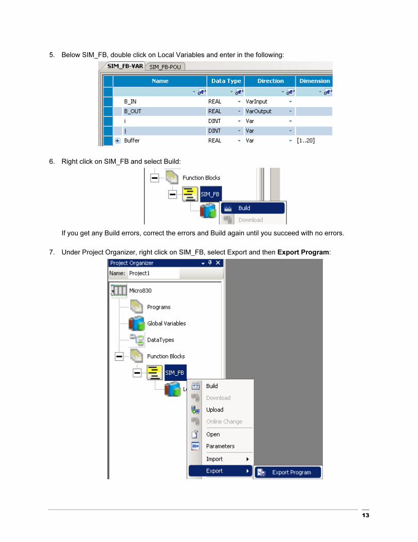
7. Under Project Organizer, right click on SIM_FB, select Export and then Export Program:

14
8. Click Export:

15
9. Browse to the saving folder location and click Save:
10. To use the SIM_FB in a future project, create a new project and right click on Micro830 under
Project Organizer, select Import, then Import Exchange File:

16
11. Click Browse, navigate to the folder location, select the file and click Open:

17
18
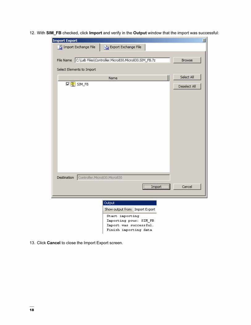
12. With SIM_FB checked, click Import and verify in the Output window that the import was successful:
13. Click Cancel to close the Import Export screen.

19
Chapter 3 - Creating a New Function
Block Program

20
Creating a New Function Block Programming
This section will show you how to create a new function block program. In this function block program, the PID standard function block will be used. A User Defined Function Block will be imported to simulate the process value.
1. Start the Connected Component Workbench from the Start Menu: Start �All Programs � Rockwell Automation � CCW � Connected Components Workbench.
Alternatively, double click on the shortcut on the Desktop .
21
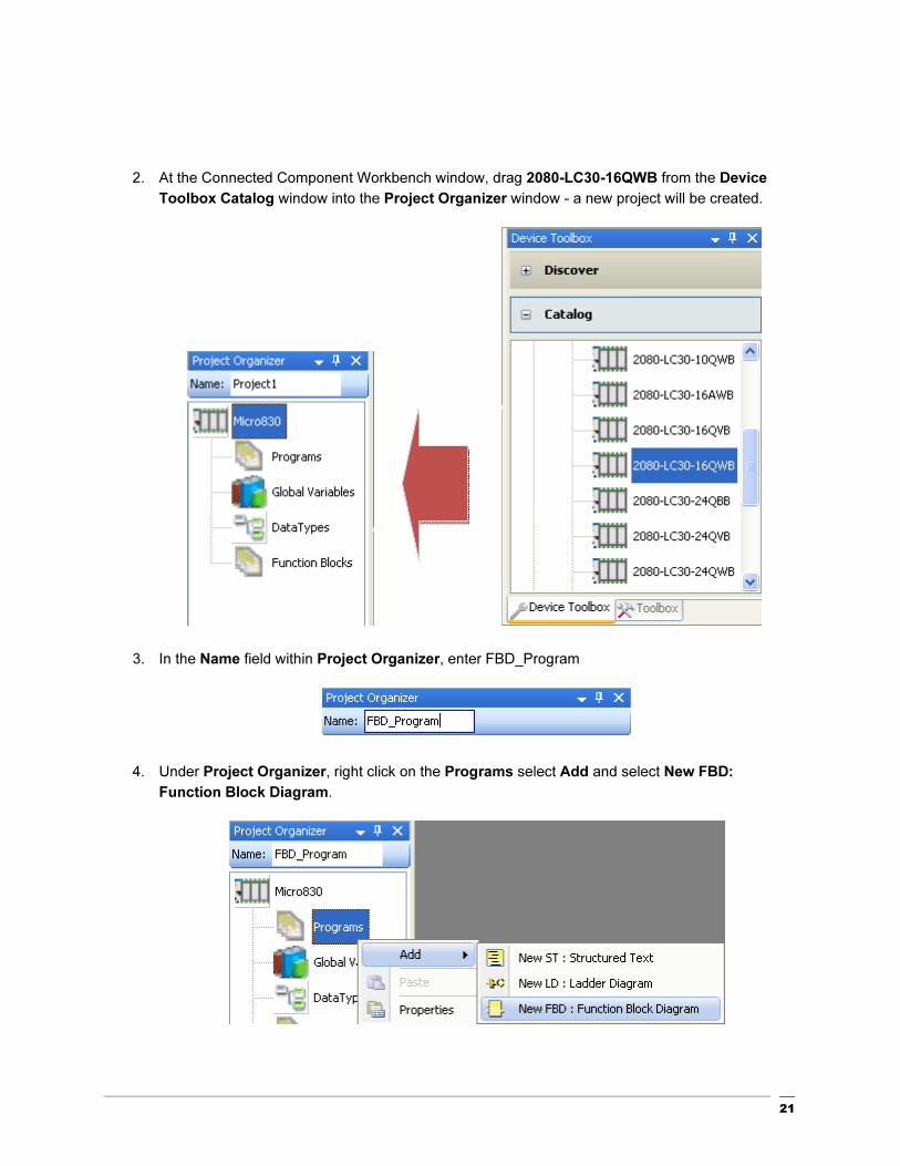
2. At the Connected Component Workbench window, drag 2080-LC30-16QWB from the Device
Toolbox Catalog window into the Project Organizer window - a new project will be created.
3. In the Name field within Project Organizer, enter FBD_Program
4. Under Project Organizer, right click on the Programs select Add and select New FBD:
Function Block Diagram.

22
5. Right click on UntitledFBD and select Rename:
6. Type in Process_SIM and Enter:
23
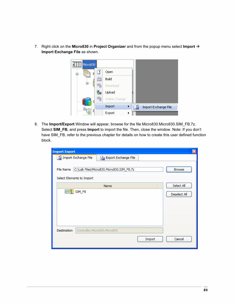
7. Right click on the Micro830 in Project Organizer and from the popup menu select Import �
Import Exchange File as shown.
8. The Import/Export Window will appear, browse for the file Micro830.Micro830.SIM_FB.7z.
Select SIM_FB, and press Import to import the file. Then, close the window. Note: If you don’t
have SIM_FB, refer to the previous chapter for details on how to create this user defined function
block.

24
9. The Function Block, SIM_FB will be imported into the Project Organizer.
The contents of the SIM_FB Structured Text program is as follows:
10. Double click on Process_SIM within the Project Organizer to start editing the Function Block
Program.
25
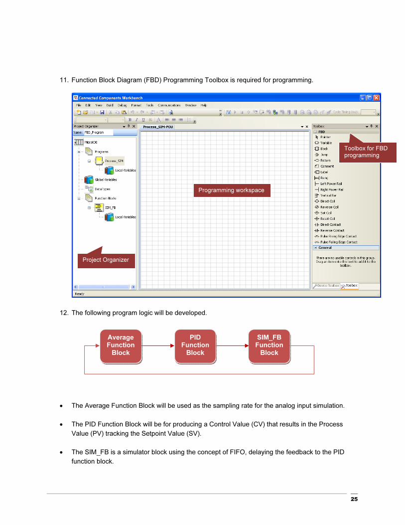
11. Function Block Diagram (FBD) Programming Toolbox is required for programming.
12. The following program logic will be developed.
• The Average Function Block will be used as the sampling rate for the analog input simulation.
• The PID Function Block will be for producing a Control Value (CV) that results in the Process
Value (PV) tracking the Setpoint Value (SV).
• The SIM_FB is a simulator block using the concept of FIFO, delaying the feedback to the PID
function block.
Toolbox for FBD programming
Project Organizer
Programming workspace
PID Function
Block
Average Function
Block
SIM_FB Function
Block

26
13. Double click on the Local Variables in the Project Organizer under the Process_SIM,
14. Enter the following variables into the Process_SIM-VAR Tab.
Name Data Type Initial Value
SV REAL 10.0
FB REAL 0
PID1_G GAIN_PID -
PID1_AT AT_PARAM -
AUTO_RUN BOOL -
INIT BOOL -
PID1_AT_EXEC BOOL -
Upon completion, the variables table should be as follows:
15. Double click on the Process_SIM, the programming workspace will appear.

27
16. Select Block from the Toolbox and drag into the Programming Workspace
17. The Instruction Block Selector window will appear.
18. Select the Average function block from the pull down menu.

28
19. The instance AVERAGE_1 will be created, click OK to proceed.
The function block will appear in the workspace.

29
20. Select Block, and drag another block into the program workspace.
21. Select IPIDCONTROLLER function block from the pull-down menu.

30
22. The Instance IPIDCONTROLLER_1 will be created.

31
23. The function block will be shown in the programming workspace.

32
24. Select Block, and drag another block into the program workspace.

33
25. Then select SIM_FB function block from the pull-down menu.
26. The Instance SIM_FB_1 will be created.

34
27. After completing Steps 15-26, the programming workspace should have 3 function blocks as
shown below.
28. Select the Variable from the Toolbox, and drag to the programming workspace. Connect it to the
SetPoint of IPIDCONTROLLER_1 Function Block as shown below:

35
29. Then select SV from the Local Variable-Process_SIM, to assign to the Setpoint of the
IPIDCONTROLLER_1.
30. SV will pass the parameter value to the SetPoint of the IPIDCONTROLLER_1
31. Repeat Steps 28-30 for the parameters shown for IPIDCONTROLLER_1
IPIDCONTROLLER Parameter Local Variable – Process_SIM Value
Feedback FB
Auto AUTO_RUN
Initialize INIT
Gains PID1_GAINS
AutoTune PID1_AT_EXEC
ATParameters PID1_AT
ErrorMode 0

36
32. After completing, the IPIDCONTROLLER_1 should appear as shown below:
33. Click on the Output of IPIDCONTROLLER_1, then connect to the B_IN of the SIM_FB_1.
As shown.

37
34. Then connect B_OUT of the SIM_FB_1 to the XIN of the AVERAGE_1.
35. Connect a variable at N of the AVERAGE_1 and enter a sample cycle value of 5. Insert a TRUE
variable for RUN.
36. Then connect XOUT of AVERAGE_1 to the Process of the IPIDCONTROLLER_1.

38
37. Click on the Output of IPIDCONTROLLER_1 again, then connect to FeedBack of
IPIDCONTROLLER_1.
38. The complete program should appear as follows:

39
39. Finally, build and save the Function Block Program. Right click on the Micro830 icon in Project
Organizer and select Build.
40. At the Output window at the bottom center of the screen, the build should show succeeded.
Click on Save icon to save your work.

40
Testing the Function Block Program
This section will show you how to test the Function Block Program created, proceed with the steps shown below.
1. In the Project Organizer, right click on Micro830, and select Download.
2. From the Connection Browser, select 2080-L30-16QWB, and click on OK.
3. The following dialog box will appear for confirmation of the downloading if the controller is in RUN mode click Yes to proceed.

41
4. If the download is successful the Output window will display Succeeded
5. The following window will appear to change from Program Mode to Run Mode. Click Yes to
proceed.
6. Click on the at the Debug Toolbar, the programming workspace will change from a white to beige background.
At the same time, the status and value of the parameter will be display on screen.

42
7. To change the SV value of the IPIDCONTROLLER_1, double click on SV. The following Variable Monitoring window will appear.
8. Change the SV to 15.0 by clicking on the Logical Value field, then hit enter.
9. Monitored the Output Value of the IPIDCONTROLLER_1, you will be able to see the value increase.
10. To stop monitoring the variable, click on at the Debug Toolbar.

43
11. Then from the Micro830 tab, click on Disconnect to go offline.

44
Chapter 4 - Creating a New Structured
Text Program

Creating a New Structured Text Program
This chapter will show you how to create a new structured text program for creating menu selections and simple mathematical calculations.
1. Start the Connected Component Workbench for the Start Menu: Start �All Programs �
Rockwell Automation � CCW � Connected Components Workbench.
Alternatively, double click on the shortcut on the Desktop .

46
2. At the Connected Component Workbench window, drag 2080-LC30-16QWB from the Device
Toolbox Catalog window into the Project Organizer window. A new project will be created.
3. At the Name field, under the Project Organizer, enter ST_Program.
4. Under the Project Organizer, right click on the Programs select Add and select New ST:
Structured Text.

47
5. Right click on UntitledST and select Rename:
6. Type Selection and Enter:
7. Double click on Selection within the Project Organizer to start editing the Structured Text
program.
8. Click at the Line no. “1” at the Selection-POU* tab.
48
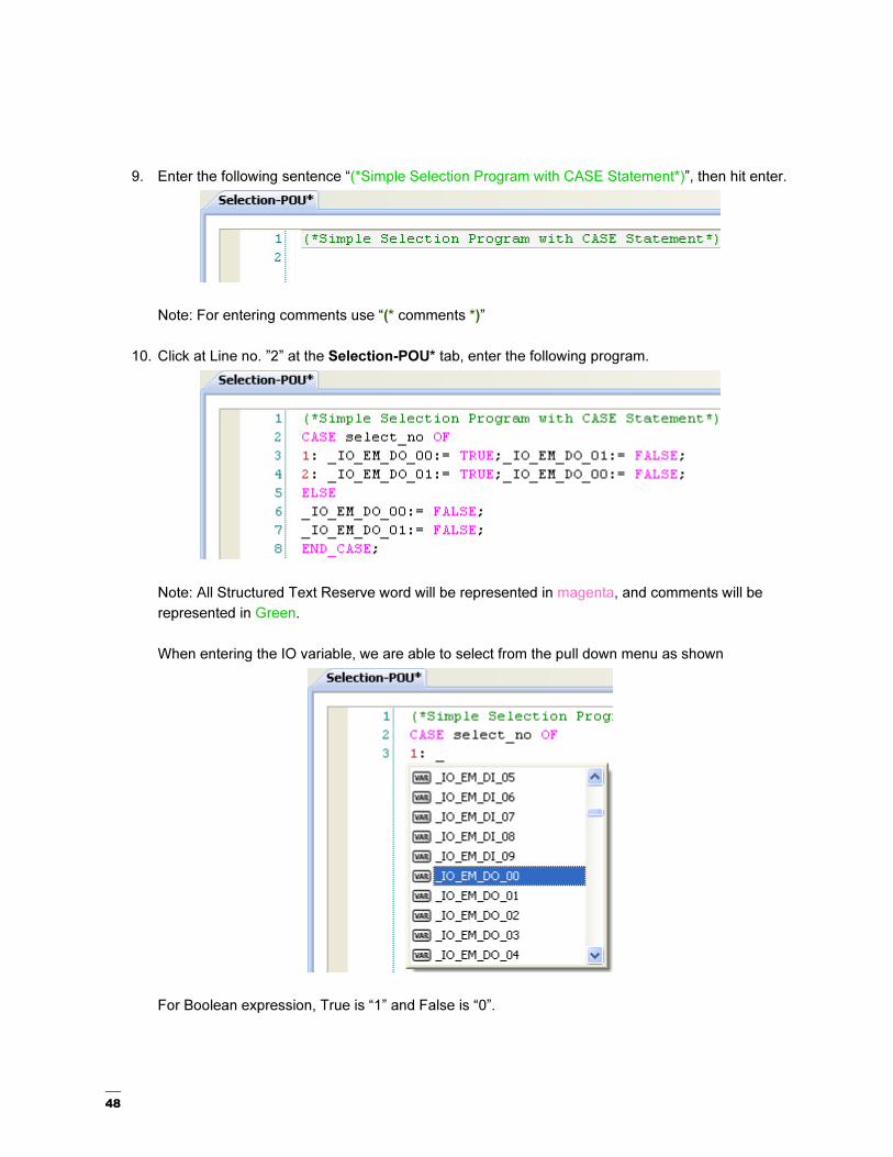
9. Enter the following sentence “(*Simple Selection Program with CASE Statement*)”, then hit enter.
Note: For entering comments use “(* comments *)”
10. Click at Line no. ”2” at the Selection-POU* tab, enter the following program.
Note: All Structured Text Reserve word will be represented in magenta, and comments will be
represented in Green.
When entering the IO variable, we are able to select from the pull down menu as shown
For Boolean expression, True is “1” and False is “0”.

49
11. Double click on the Local Variables under the Selection programs to define a new variable.
12. Create an integer variable select_no as shown:
13. At the Project Organizer, double click on the Global Variables to create the Alias for the outputs.
14. At Micro830-VAR tab, enter Output_0 at Alias for _IO_EM_DO_00 and Output_1 at Alias for
_IO_EM_DO_01.

50
15. Finally, build and save the structured text programming. Right click on the Micro830 icon in
Project Organizer and select Build.
16. At the Output window at the bottom center of the screen, the build should show succeeded.
Click on Save icon to save your work.

51
Inserting a Function Block in a Structured Text Program
This section will show you how to insert at function block in the existing Structured Text Program.
1. Double click on the Selection, to edit.
2. At Line 10 of the Selection-POU* tab, enter the following sentences
3. At line 13 of the Selection-POU* tab, enter “AV” and select AVERAGE from the pull down menu.
4. Then key in “ ( “ the following pull down menu will appear. Select the <Create New Instance>

52
5. The following dialog box will appear, AVERAGE_1 is created.
Note: 3 Inputs are required for Average function block, similar to Ladder Logic Representation.
RUN, XIN,N parameter will be required.
53
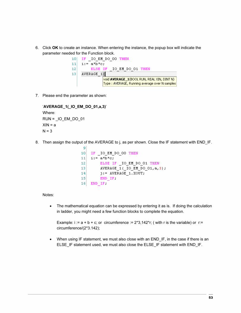
6. Click OK to create an instance. When entering the instance, the popup box will indicate the
parameter needed for the Function block.
7. Please end the parameter as shown:
‘AVERAGE_1(_IO_EM_DO_01,a,3)’
Where:
RUN = _IO_EM_DO_01
XIN = a
N = 3
8. Then assign the output of the AVERAGE to j, as per shown. Close the IF statement with END_IF.
Notes:
• The mathematical equation can be expressed by entering it as is. If doing the calculation
in ladder, you might need a few function blocks to complete the equation.
Example: i := a + b + c; or circumference := 2*3,142*r; ( with r is the variable) or r:=
circumference/(2*3.142);
• When using IF statement, we must also close with an END_IF, in the case if there is an
ELSE_IF statement used, we must also close the ELSE_IF statement with END_IF.

54
9. In completion of writing the program, variables used must be created. Double click on the Local
Variables under the Selection programs to create variable.
10. Create the following variables for the program
Name Data Type Initial Value
a Real 0.0
b Real 1.5
c Real 3.142
i Real 2.0
j Real 0.0
The Selection-VAR tab should look like the following:
11. Finally, build and save the structure text programming. Right click on the Micro830 icon in Project
Organizer and select Build.

55
12. At the Output window at the bottom center of the screen, the build should show succeeded.
Click on Save icon to save your work.

56
Testing the Function Block Program
This section will show you how to test the Function Block Program created. In continue to the steps in Creating New Function Block Program, proceed with the steps shown below.
1. In the Project Organizer, right click on Micro830, and select Download to download the program:
2. From the Connection Browser, select 2080-L30-16QWB, and click on OK.
3. The following dialog box will appear for confirmation of the downloading if the controller is in RUN mode. Click on Yes to proceed.

57
4. In the completion of downloading the program, the Output window will display Succeeded
5. The following window will appear to change from Program Mode to Run Mode. Click on Yes to proceed.
6. Click on the at the Debug Toolbar, the programming workspace will change from white background to gray background.
7. To simulate the variable, run over the and the following popup dialog box will appear. Click on
the dialog box to monitor.

58
8. The Variable Monitoring window will appear.
9. Change the value at the Logical Value of the variable select_no. to simulate the program.
Simulation for select_no using the demo kit output indicators:
• In the demo kit, Output 0 should be lit when the select_no variable is 1. At the Logical
Value of select_no. change to 2. Now, Output 0 should turn off, and Output 1 should lit.
• Change the value of select_no variable to 0 or 3, both Output 0 and Output 1 should turn
off.
• The program logic is written so that if the value is not 1 or 2, both Output 0 and Output 1
should turn off.
59
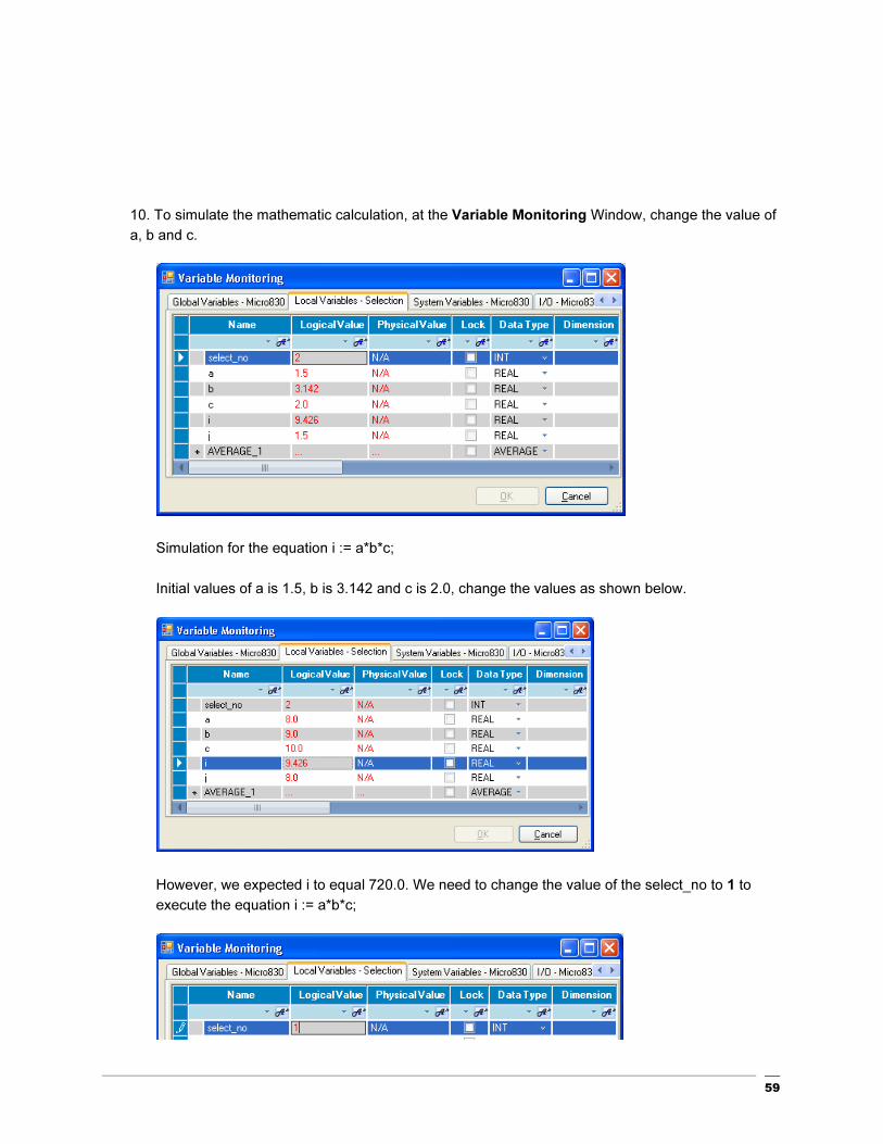
10. To simulate the mathematic calculation, at the Variable Monitoring Window, change the value of
a, b and c.
Simulation for the equation i := a*b*c;
Initial values of a is 1.5, b is 3.142 and c is 2.0, change the values as shown below.
However, we expected i to equal 720.0. We need to change the value of the select_no to 1 to
execute the equation i := a*b*c;
60
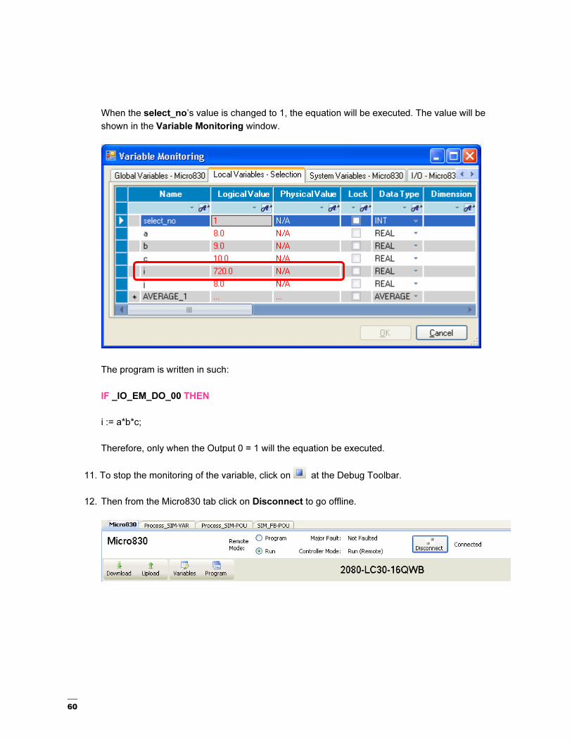
When the select_no’s value is changed to 1, the equation will be executed. The value will be
shown in the Variable Monitoring window.
The program is written in such:
IF _IO_EM_DO_00 THEN
i := a*b*c;
Therefore, only when the Output 0 = 1 will the equation be executed.
11. To stop the monitoring of the variable, click on at the Debug Toolbar.
12. Then from the Micro830 tab click on Disconnect to go offline.

61
Chapter 5 - Using Connected Components Workbench with PanelView™ Component

62
Using Connected Components Workbench with PanelView Component
Before you begin, you should already have a general knowledge of how to use the Connected
Components Workbench software and how to create an application for you Micro800 controller. If you do
not have this knowledge, please review the Micro800 and CCW Getting Started Guide, Publication 2080-
QR001B-EN-P.
The recommended Modbus RTU network topology for a Micro800 and PanelView Component is to
configure the Micro800 controller as a slave device, and the PanelView Component as the master device.
Therefore that is the configuration that will be discussed and configured in this guide.

63
Mapping Variables to Modbus Registers
The Micro800 supports the following Modbus registers.
Address Range Data Type Access
Output Coils 000001-065536 Boolean Read/Write
Input Coils 100001-165536 Boolean Read Only
Input Registers 300001-365536 Word (16-bit) Read Only
Holding Registers 400001-465536 Word (16-bit) Read/Write
1. Create a new CCW project for your Micro800 controller, and create a Global Variable called
DATA with data type INT and attribute ReadWrite.
2. Open the Modbus Mapping table by following the steps below.
Double-click Modbus Mapping from the Micro800 Device Configuration tree – this will launch the Modbus Mapping table shown below.

64
3. Add a Variable to the Mapping table by following the steps below.
Double-click here to launch the Variable Selector window.
Select the User Global Variables tab.
Then click here to select the DATA variable.
Then click OK.
65
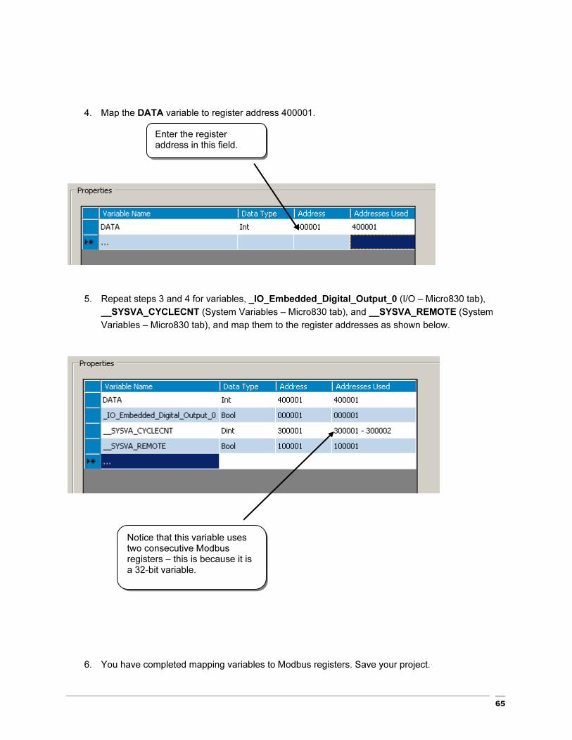
4. Map the DATA variable to register address 400001.
5. Repeat steps 3 and 4 for variables, _IO_Embedded_Digital_Output_0 (I/O – Micro830 tab),
__SYSVA_CYCLECNT (System Variables – Micro830 tab), and __SYSVA_REMOTE (System
Variables – Micro830 tab), and map them to the register addresses as shown below.
6. You have completed mapping variables to Modbus registers. Save your project.
Enter the register address in this field.
Notice that this variable uses two consecutive Modbus registers – this is because it is a 32-bit variable.
66
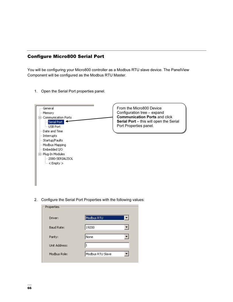
Configure Micro800 Serial Port
You will be configuring your Micro800 controller as a Modbus RTU slave device. The PanelView
Component will be configured as the Modbus RTU Master.
1. Open the Serial Port properties panel.
2. Configure the Serial Port Properties with the following values:
From the Micro800 Device Configuration tree – expand Communication Ports and click Serial Port – this will open the Serial Port Properties panel.

67
3. Expand Advanced Settings to configure the Protocol Control properties with the following
values:
If you are using RS485, you can set the Media property to RS485 and leave the remaining
settings the same.
4. You have completed configuring your serial port for Modbus. Build and save your project, and
then download it to your controller.

68
Create an Offline PanelView Component Application
1. Add a PanelView Component device to your project.
From the Device Toolbox, click and drag a PanelView Component device into
your Project Organizer.

69
2. Launch PanelView Component Design Station.
Double-click the PanelView Component icon in the Project Organizer.
The PanelView Component Design Station Startup pane will open as a new tab in the main project window.

70
3. Select the PanelView Component platform and create a new application.
Click the Platform drop-down and select 2711C-T6T.
Click the Create & Edit button.
The application will launch in a new tab in the main project window and default to the
Screens tab.

71
4. Setup Communication settings to configure your PanelView Component as a Modbus Master to
communicate to your Micro800 controller.
Select the
Communication tab.

72
Configure the Driver settings as shown below – the default settings will work for RS232. If using
RS485, change the Port settings to RS422/485 (Half-duplex).
RS232
RS485
Select Modbus from the Serial Protocol dropdown list.

73
5. In the Controller Settings, configure a controller with settings as shown below.
6. Create tags addressed to the tags you created earlier in your Micro800. Refer to the section
called “Mapping Variables for Modbus Registers” for details on how to create the Micro800 tags.
Everything can be left as default except for the first three settings.
Click the Tags tab.
Click Add Tag.

74
Create the following tags as shown below – make sure to choose the correct data type.
7. Create a screen display with objects linked to the tags you just created.
Create a maintained pushbutton linked to tag, Output_0. This is not typical practice, as a direct output should not be turned on/off directly, but is done for demonstration purposes.
From the main project window, click on the Screens tab.
Drag and drop a Maintained Pushbutton object to the screen.
75
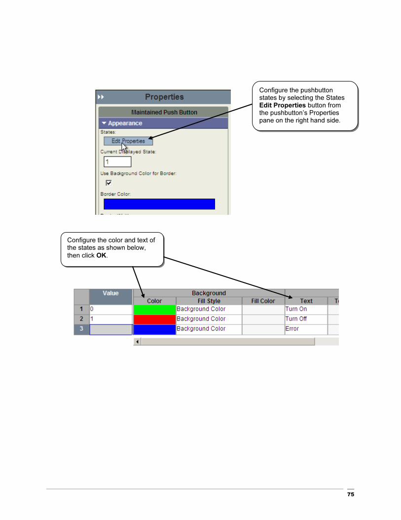
Configure the pushbutton states by selecting the States Edit Properties button from the pushbutton’s Properties pane on the right hand side.
Configure the color and text of the states as shown below,
then click OK.
76
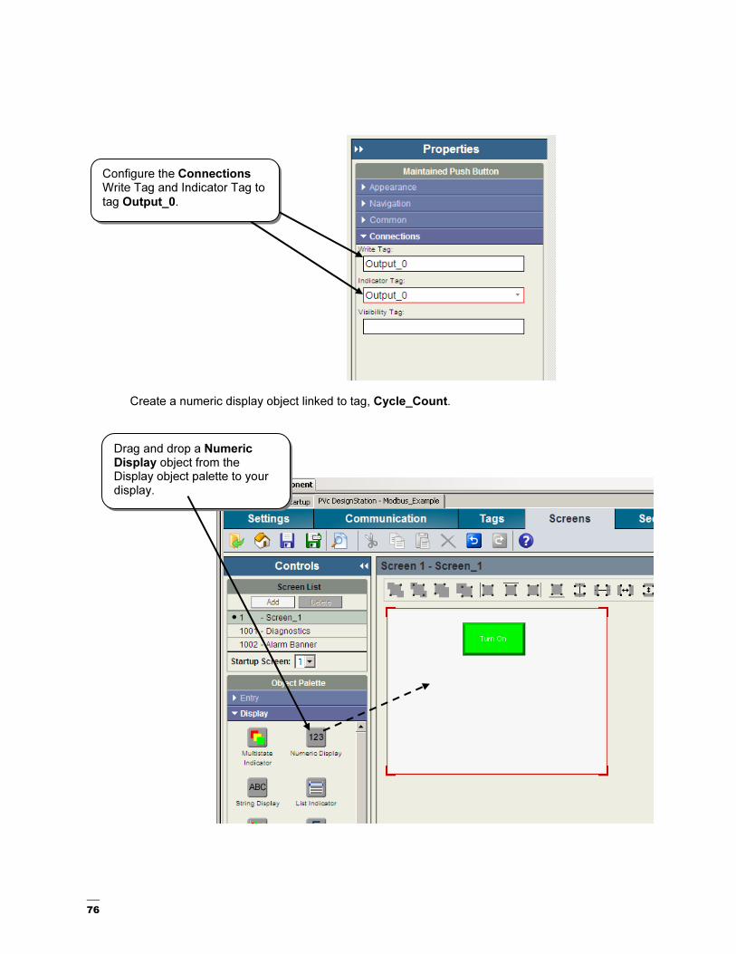
Create a numeric display object linked to tag, Cycle_Count.
Configure the Connections Write Tag and Indicator Tag to
tag Output_0.
Drag and drop a Numeric Display object from the Display object palette to your display.

77
In the Numeric Display Properties pane, select the Format tab, and configure Number of Digits to 12.
In the Numeric Display Properties pane, select the Connections tab, and configure Read Tag to Cycle_Count.
78
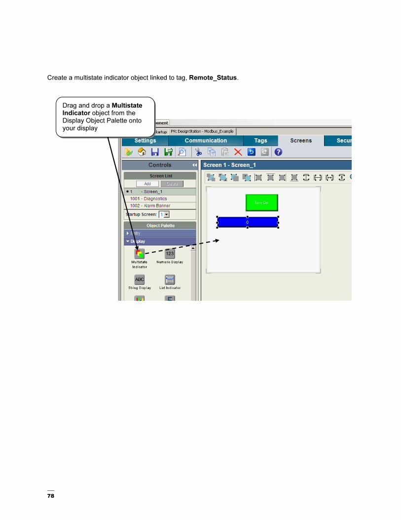
Create a multistate indicator object linked to tag, Remote_Status.
Drag and drop a Multistate Indicator object from the Display Object Palette onto your display
79
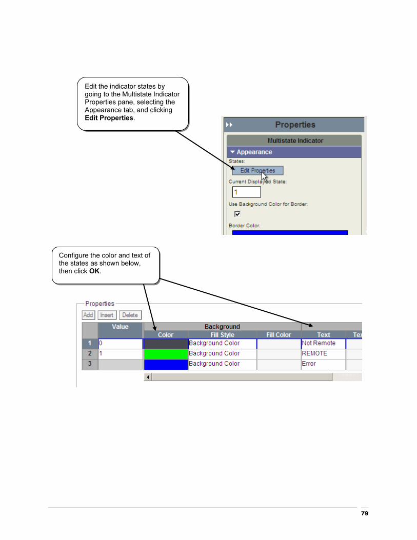
Edit the indicator states by going to the Multistate Indicator Properties pane, selecting the Appearance tab, and clicking Edit Properties.
Configure the color and text of the states as shown below, then click OK.

80
Create a Numeric Input Enable object linked to tag, DATA.
Drag and drop a Numeric Entry object from the Entry Object Palette onto your display.

81
In the Numeric Entry Properties pane, select the Format tab, and configure the properties as shown here.
In the Numeric Entry Properties pane, select the Connections tab, and configure the Write Tag and Indicator Tag to, DATA.

82
Add a Goto Config button to your display.
Drag and drop a Goto Config object, from the Advanced Object Palette, onto your display.

83
Your display should look like the following.
8. You are done creating your PanelView Component application. Save your application.

84
Transferring an Offline PVc Application to a PVc Terminal
Hardware Used
PanelView Component C600 – 2711C-T6T
This section will demonstrate how to transfer an offline PVc Application to a PVc terminal. Transferring
the file involves copying the application to a USB or SD flash media, and then inserting it into the PVc
terminal, and copying it to the terminal.
1. From your CCW project, launch the PVc DesignStation Startup pane.
Double-click the PanelView Component icon in the Project Organizer.
The PanelView Component Design Station Startup pane will open as a new tab in the main project window.

85
2. Insert either a USB flash drive, or SD card into your computer.
3. Set up a file transfer to copy the application to your USB/SD flash media.
Click File Transfer.
Click New Transfer. This will launch the File Transfer Wizard.

86
Configure the File Transfer as shown below, and then click Transfer.
Browse to the root of your flash media, and then click Save. This will save the PVc application file
(.CHA) to your flash media.

87
4. Remove the flash media from your computer and insert into PanelView Component terminal.
5. Copy the application from your flash media to your PanelView Component.
Click File Manager.
Select USB or SD as your Source.
Then click Copy to copy the application to the PVc’s internal memory.

88
6. You have completed transferring an offline application to your PVc terminal.
Select Internal as your Source, and you’ll notice that your application has been copied to your terminal.

89
Cabling the Micro800 to a PanelView Component
Hardware Used
PanelView Component C600 – 2711C-T6T
RS232 Cable, 1761-CBL-xxxx or 2711-CBL-PMxx
RS485 Adapter, 1763-NC01
1. For RS232 communications, you will need an 8-pin Mini-DIN to 9-pin D-shell null modem cable.
See table below for recommended cables.
0.5 m (1.6 ft) 1761-CBL-AP00
2 m (6.6 ft) 1761-CBL-PM02
5 m (16.4 ft) 2711-CBL-PM05
10 m (32.8 ft) 2711-CBL-PM10
For RS485 communications, you will need to use a 1763-NC01 adapter, and wire the
recommended twisted pair shielded cable as shown below. The recommended cable is Belden
3105A or equivalent (two-wire shielded twisted pair with drain). Note: Because both devices’
serial ports are non-isolated, connect the shield/drain wire at one end only to prevent a ground
loop.
There is no need for terminating resistors. The PanelView Component has an internal 121 ohm
resistor across the R and R- terminals, and the Micro800 is terminated by jumpering TERM to A
on the 1763-NC01 adapter.
2. Connect cables, and test the application.
RS232 - Connect the serial cable from the 8 pin Mini-DIN port on the Micro830 to the D-shell
connector on the PanelView Component terminal.

90
RS485 – Connect the 1763-NC01 adapter to the Mini-DIN port on the Micro830 controller.
Connect the RS485 cable from the 1763-NC01 adapter to the RS485/422 port on the PanelView
Component.
3. Confirm the controller is in RUN mode and that no faults exist.
4. Load PanelView Component application.
Click File Manager.
Select your application, and click Run.
91
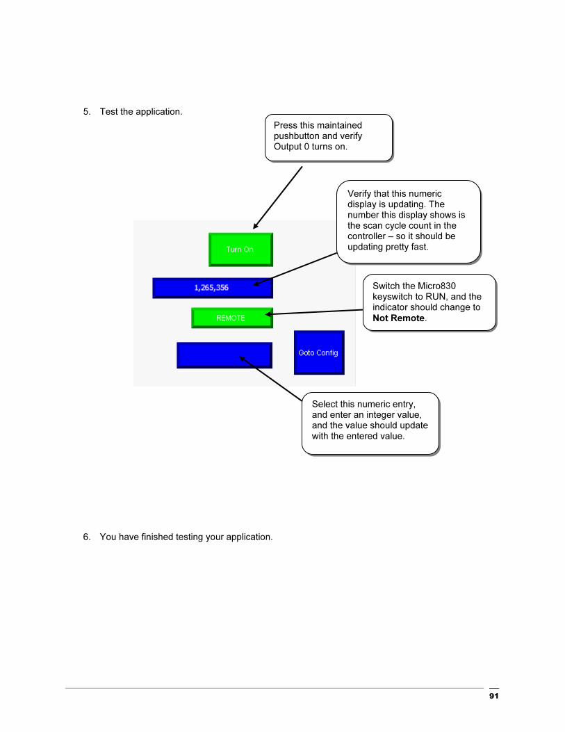
5. Test the application.
6. You have finished testing your application.
Press this maintained pushbutton and verify Output 0 turns on.
Verify that this numeric display is updating. The number this display shows is the scan cycle count in the controller – so it should be updating pretty fast.
Switch the Micro830 keyswitch to RUN, and the indicator should change to
Not Remote.
Select this numeric entry, and enter an integer value, and the value should update with the entered value.

92
Chapter 6-
Using Connected Components Workbench with PowerFlex® Drives

93
Hardware Used
• PowerFlex 4-Class Drive
• 1203-USB
• Modbus Cable (Flying leads to RJ45)

94
Adding a PowerFlex 4 Drive to a CCW Project
This chapter will show you how to add a PowerFlex 4-Class Drive to a CCW Project.
1. Review the Getting Started Guide (Pub# 2080-QR001B-EN-P) to learn how to create a new project and
add a controller. Once that’s done, the screen should look like the following and click on Device Toolbox.

95
2. Expand the Drives folder within Device Toolbox:
3. Click on the PowerFlex 4 icon, hold and drag it across to the Project Organizer, then release:
Note: The default name for the drive is PowerFlex4_1* to change this, just right click on it and select
rename to enter the desired name. Also, notice the asterisk (*) next to the project name and the drive
that indicates the project has been modified and needs to be saved. Once the project is saved, the
asterisk will disappear.

96
4. Double click on the PowerFlex 4_1 icon and you should see the Device Configuration screen:
97
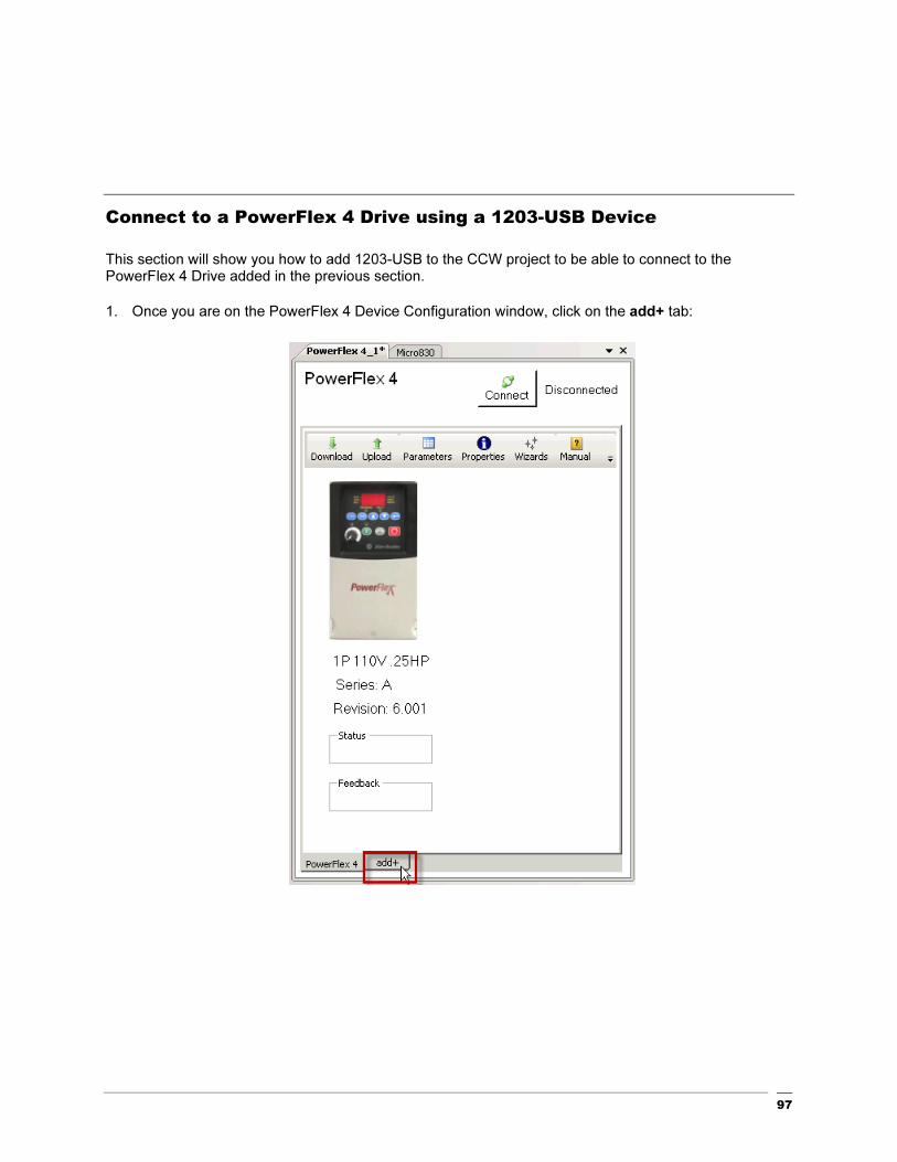
Connect to a PowerFlex 4 Drive using a 1203-USB Device
This section will show you how to add 1203-USB to the CCW project to be able to connect to the PowerFlex 4 Drive added in the previous section.
1. Once you are on the PowerFlex 4 Device Configuration window, click on the add+ tab:

98
2. Double-click on the 1203-USB:
3. Click on the 1203-USB tab added on the bottom:

99
4. Before connecting to the Drive, you must install the 1203-USB drivers and configure a new DF1
connection in RSLinx (refer to publication DRIVES-UM001B-EN-P for more details). Click the Connect
button:

100
5. Expand the DF1 connections and look for the 01,AB DSI representing the 1203-USB, select it and then
click OK.

101
6. Notice the green background around the drive in the Project organizer meaning that you are now
connected to the PowerFlex 4 using the 1203-USB. Click on the PowerFlex 4 drive tab:

102
7. Select the Wizards as shown:

103
8. Select the PowerFlex 4 Startup Wizard and then click Select.
9. The following screen will show. Click Next to skip this welcome screen:

104
10. Click on Reset Parameters :
10. Click Yes and then click Next:

105
11. In this quick start we will use the default Motor Data. Click Next:
12. Select as shown and then click Next:

106
13. To complete the Direction Test follow these steps:
a. Click to clear the present fault (F048) if showing.
b. Enter the desired reference. For this quick start we’ll use 30Hz and then click .
c. A speed reference acknowledgement window will appear to accept a parameter change.
Click Yes.
d. By now the motor should be rotating at reference speed. Verify that the motor direction of
rotation is correct and then select the Yes radio button.
e. You are done with the direction test. Click Next to continue.

107
14. Select as shown and then click Next:
108
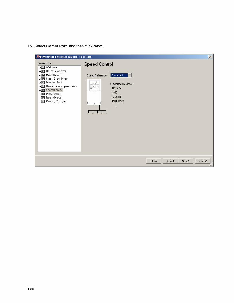
15. Select Comm Port and then click Next:

109
16. Set the Start Source to Comm Port to eventually trigger the Preset Freqs shown below. Select as
shown and then click Next:

110
17. Select as shown and then click Next:

111
18. Click Finish:
19. Save the project by clicking and the following window will appear. Click Yes to upload the drive
parameters.

112
Configuring the Controller for Modbus Communication with a
PowerFlex 4
This section will show you how to configure the Micro830 for Modbus communication using the Serial plug-in module.
1. To configure the controller plug-ins, double click on the Micro830 icon in the Project Organizer to
bring up the following screen:

113
2. Add an isolated serial plug-in to slot 1 by right clicking on the graphic of the first plug-in slot and
selecting 2080-SERIALISOL:
3. The device configuration window will now look like this:
114
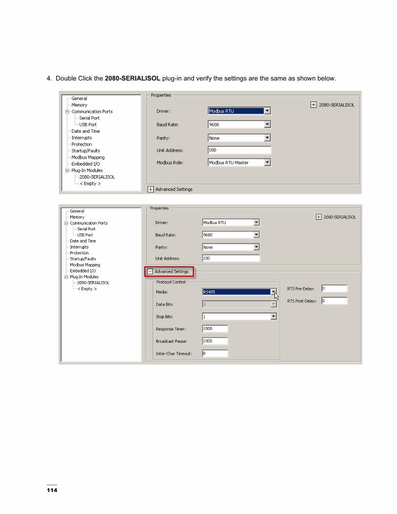
4. Double Click the 2080-SERIALISOL plug-in and verify the settings are the same as shown below.

115
5. Right Click on Micro 830, then select Build.

116
Programming the Controller for Modbus Communication with a
PowerFlex 4
This section will show you how to program the Micro830 for Modbus messaging with a PowerFlex 4.
1. Start by creating a new ladder diagram program by right clicking on Program. Move the cursor
over the Add tab and select New LD :Ladder Diagram.
2. A new ladder icon will appear as shown:

117
3. Double click on the new ladder icon:
4. Open the Toolbox tab if it is not already open
118
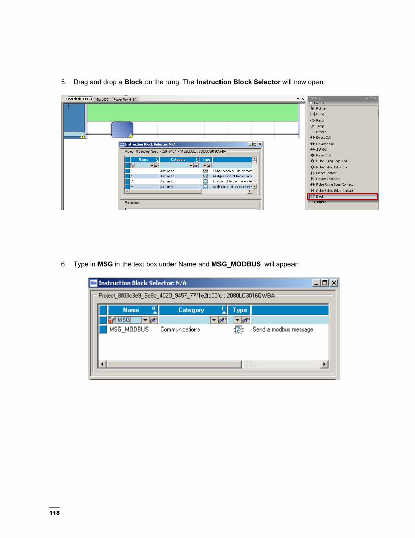
5. Drag and drop a Block on the rung. The Instruction Block Selector will now open:
6. Type in MSG in the text box under Name and MSG_MODBUS will appear:

119
7. Double click on the MSG_MODBUS and the following function block will appear:

120
8. To use the block, you need to configure it. To find help on the instruction blocks, in this case the MSG
Modbus, go to Help, Search, click on Local Help, and enter MSG Modbus in the search box.

121
9. Here you will find the information on the inputs and outputs of the block.
10. For the Cancel parameter, click on the upper part of the blue box and double click on the input from
the Micro830 you want to assign, in this case, Input 0 will be selected.
122
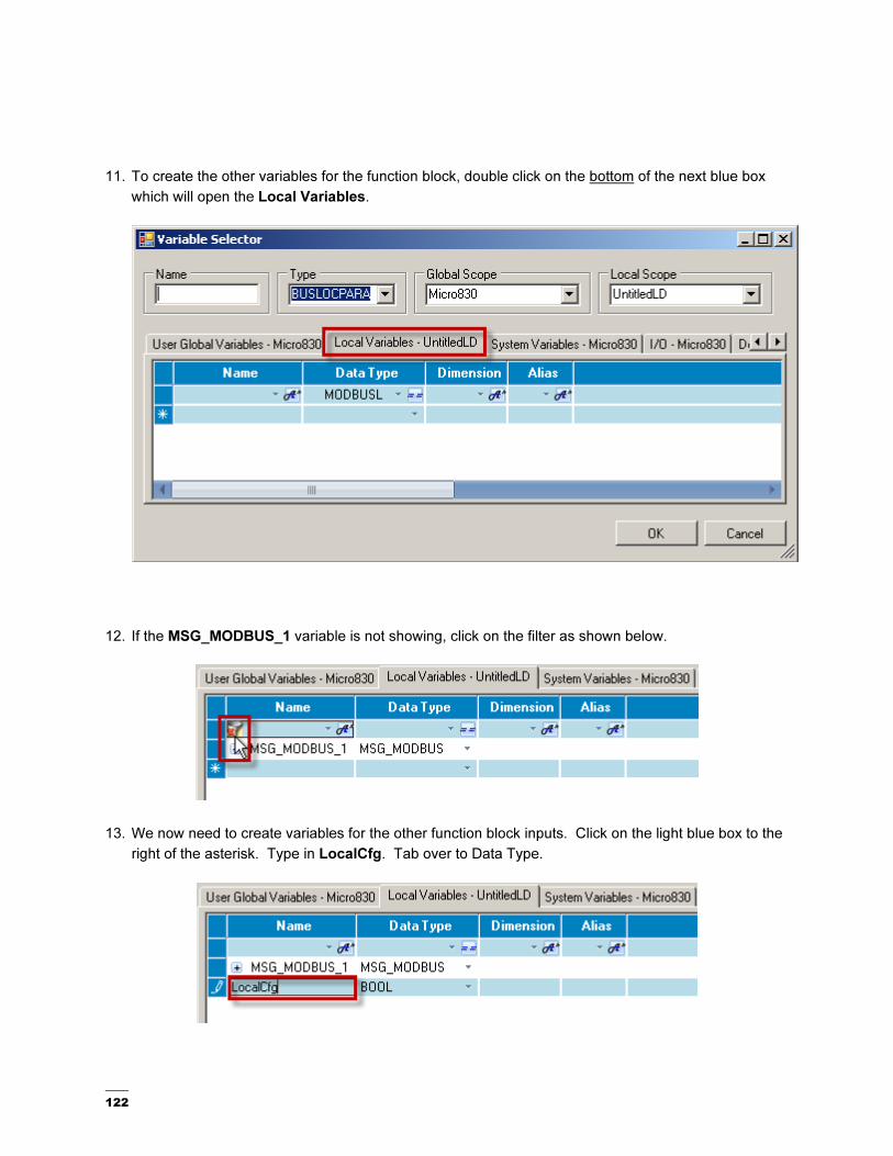
11. To create the other variables for the function block, double click on the bottom of the next blue box
which will open the Local Variables.
12. If the MSG_MODBUS_1 variable is not showing, click on the filter as shown below.
13. We now need to create variables for the other function block inputs. Click on the light blue box to the
right of the asterisk. Type in LocalCfg. Tab over to Data Type.

123
14. Type in MODBUSLOCPARA. See step 9 for where this data type assignment came from. You will
note as you begin typing, the name will populate. Pay attention to the last half of the word to ensure
you have the correct data type. Press Enter.
15. Type in TargetCfg in the light blue box to the right of the asterisk. Type in MODBUSTARPARA under
data type. Press Enter.
16. Type in LocalAddr in the light blue box to the right of the asterisk. Type in MODBUSOCADDR under
data type. Hit Enter and then click OK on this window to go back to the function block view.

124
17. Assign the appropriate variables to each of the Input boxes by clicking on top of the box for each and
select the corresponding variable.
18. Complete the selection to look like this.

125
19. To trigger the message, drag and drop a Direct Contact to the left of the msg function block from the
Toolbox as shown below. Notice the Variable Selector will appear.
20. In the Variable Selector, click on the I/O – Micro830 tab.

126
21. Double click on the Input you need to trigger the message. In this case, select by double clicking
_IO_EM_DI_01 and the selector will close.

127
22. After assigning the Direct Contact, the ladder now looks like this. Double click (bottom of the box) on
one of the Local Variable Inputs to Display the Variable Selector.

128
23. Once the Variable Selector window appears, complete the following steps:
a. Expand the Local Variables created (LocalCfg, TargetCfg…).
b. You may have to use the scroll bar at the bottom of the variable tab to see the Initial
Values. For ease of use, you can move the Initial Value column by dragging the top of
the column and moving it next to Data Type.
c. Set up the variables by clicking on the initial value field for each variable and enter the
values shown in steps i, ii, and iii. For more information on the initial values refer to the
message instruction CCW Help file:
i. Channel = 2 (2 is for the embedded serial port and 5 – 9 would be for different
slot numbers the serial port could be located)
ii. Cmd = 3 (3 is for read holding registers and 16 would be for writing multiple
registers. For a complete list and description of all the commands refer to the
message instruction CCW Help file.)
iii. For more information on PowerFlex 4 address and node settings refer to drives
Publication 22A-UM001I-EN-E.

129
Configuring the Embedded Serial Port on the Micro830.
1. For the embedded serial port on the Micro830, click the Serial Port under Communication Ports, and
change the Driver to Modbus RTU. If necessary, change the other properties to match the screen
shot below.

130
2. Open the Advanced settings and select RS485 for Mode.
3. Go to the Variables section and change the LocalCfg Channel to 2.
4. Build the project.

131
Cabling the Controller to a PowerFlex 4 Class Drive
This quick start will show you how to physically connect a PowerFlex 4 class Drive to the Micro830.
1. Wire the Micro830 Modbus Plugin to the drive as shown below. The PowerFlex 4 comes with a built-in
RS485 DSI port where Modbus Communication is available. In order to communicate between the Micro
830 and PowerFlex 4, the Serial Communication port on the Micro830 will be configured as RS485 for the
communication media. Below is the basic connection between the Micro830 and PowerFlex 4 using the
recommended Belden 3105A twisted pair cable.
2. Connect the USB cable to the USB port shown below to establish communication between the PC and
the Micro830. If this is the first time you connect to the controller, refer to the Getting Started Guide, Pub#
2080-QR001B-EN-P, to establish communications between RSLinx and a Micro830 via USB.
PowerFlex 4
Micro 830
Tx RX D- (Pin 5)
Tx Rx D+ (Pin 4)
Drives Adapter Plug # AK-U0-RJ45-
TB2P

132
Testing Modbus Communication with a PowerFlex 4 Class Drive
In this section, you will test the Modbus message created in the previous sections. The rung below will
trigger an input on the controller that will execute a Modbus read message.
1. Start with the rung shown below. For information on how to create this rung refer to the previous
sections starting on Chapter 6.
2. Build and download to the controller. If you are not familiar with the download steps, refer to the
Getting Started Guide, Pub# 2080-QR001B-EN-P.

133
3. Once connection is established with the controller, start debugging by pressing in the top
menu bar. The following should show the Modbus message in debug mode:
4. Trigger Input _IO_EM_DI_01 to read a Modbus message from the controller. Notice that the
function block input LocalAddr now is displaying a WORD value.

134
5. Stop debugging by clicking on the stop button on the top menu. To use the WORD value read
from the drive in the previous step, a copy of this value needs to be assigned to a new variable
using a 1 gain function block. In the Toolbox, click and drag a Block as shown below to the end
of the rung.

135
6. Type 1, select the 1 gain function block and click OK.
7. A new 1 gain function block has now been added. Double click on the bottom of the input box to
add the desired input to be copied.
136
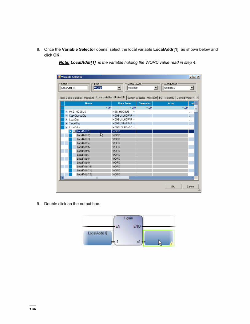
8. Once the Variable Selector opens, select the local variable LocalAddr[1] as shown below and
click OK.
Note: LocalAddr[1] is the variable holding the WORD value read in step 4.
9. Double click on the output box.

137
10. Create a new local variable as shown below. For this quick start type Logic_Status as the name
of the variable, select WORD as its data type and click OK.

138
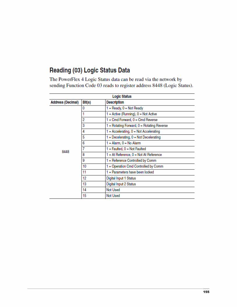
11. To interpret the data read by the message refer to Appendix A, Reading (03) Logical Status Data
table. This table can be used to determine the meaning of each of the 16 bits of the WORD. Start
by adding a Rung as shown below.
12. Select, drag and drop a Direct Contact from the toolbox to the start of the newly added rung.
139
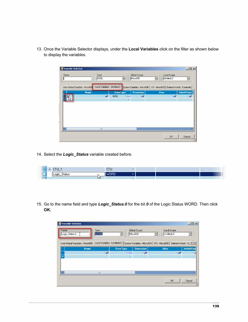
13. Once the Variable Selector displays, under the Local Variables click on the filter as shown below
to display the variables.
14. Select the Logic_Status variable created before.
15. Go to the name field and type Logic_Status.0 for the bit 0 of the Logic Status WORD. Then click
OK.

140
16. Select, drag and drop a Direct Coil to the end of the rung as shown below.
17. In the Variable Selector I\O Micro830 tab, select _IO_EM_DO_00 as the embedded output for
this rung. Then click OK.

141
18. Repeat steps 11 – 17 from this quick start to add an additional Logic Status rung that will read bit
7 to determine whether the drive is faulted or not.
19. Build and download at this time. Now you are ready to start debugging by clicking the button
on the top menu bar and the ladder should look as shown below.

142
20. Trigger Input 1 (_IO_EM_DI_01) as shown below and notice that the Modbus message will return
the status WORD shown before to be 1037. Now it can be shown that at the bit level
Logic_Status.0 is true stating that the Drive is READY and showing this status by enabling
Output 0 (_IO_EM_DO_00).

143
Sending a Write Message to the Drive to Start, Stop and Change Speed
In this section, you will change the Modbus message to write to the drive and be able to control the drive.
To do this, you will need to add some additional ladder logic to be able to Start, Stop and set a Speed on
the drive. This section of the quick start will modify the modbus message used in the previous section to
read the drive’s status.
1. Start by double clicking on the LocalCfg input as shown:
144
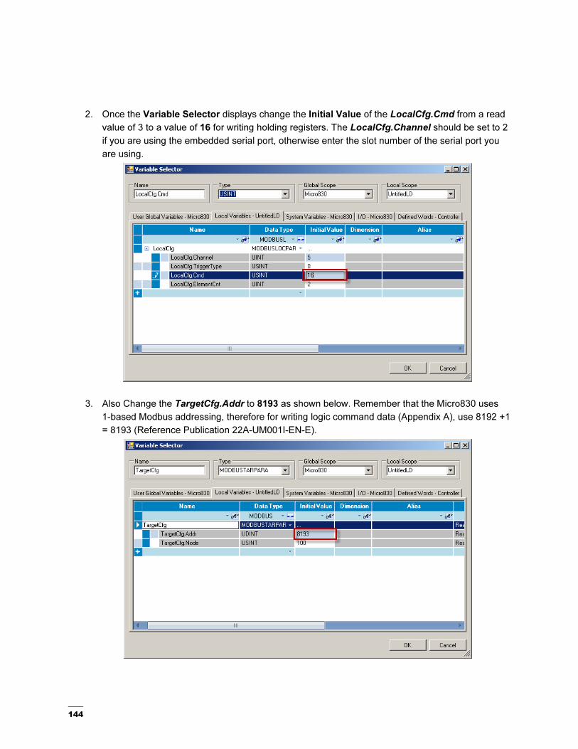
2. Once the Variable Selector displays change the Initial Value of the LocalCfg.Cmd from a read
value of 3 to a value of 16 for writing holding registers. The LocalCfg.Channel should be set to 2
if you are using the embedded serial port, otherwise enter the slot number of the serial port you
are using.
3. Also Change the TargetCfg.Addr to 8193 as shown below. Remember that the Micro830 uses
1-based Modbus addressing, therefore for writing logic command data (Appendix A), use 8192 +1
= 8193 (Reference Publication 22A-UM001I-EN-E).

145
4. Now that the Modbus message will be writing to the drive, create a rung that will trigger a 1 gain
copy function block to hold the value that will be written to the drive. Therefore toggling the bit in
front of the 1 gain will determine if the controller sends a Start, Stop, or Speed change message.
Start by selecting, dragging and dropping a Rung as shown below.
5. Select, drag and drop a Block.
146
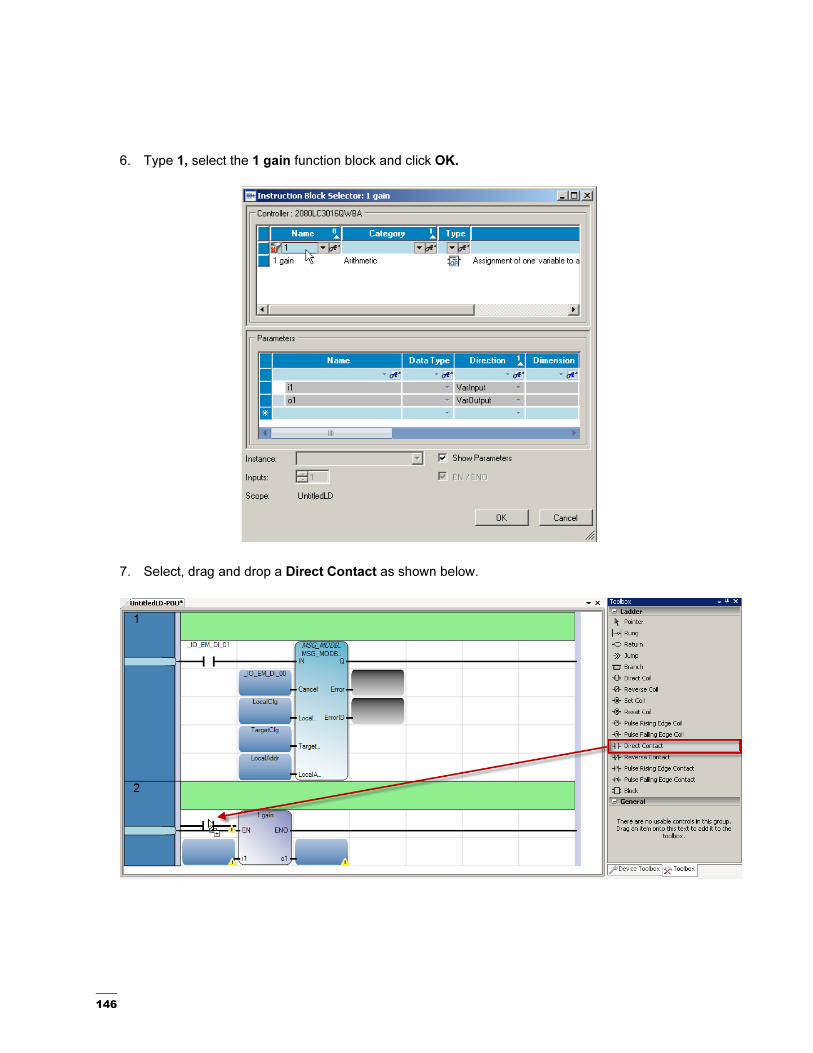
6. Type 1, select the 1 gain function block and click OK.
7. Select, drag and drop a Direct Contact as shown below.

147
8. From the I/O – Micro830 tab, select _IO_EM_DI_01 (Input1).
9. Select, drag and drop a Direct Coil as shown below.
148
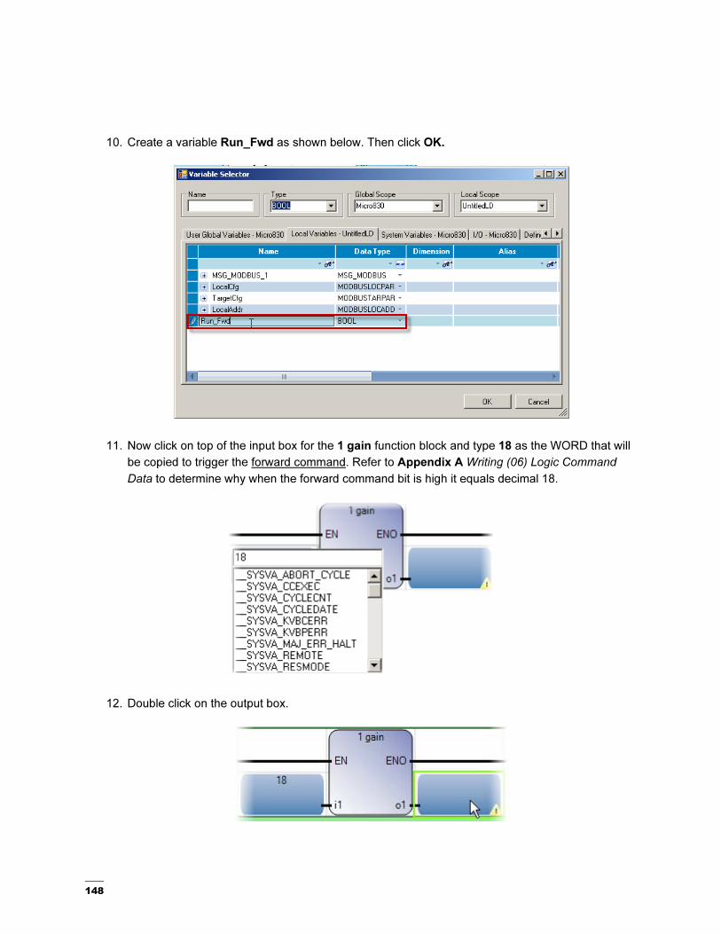
10. Create a variable Run_Fwd as shown below. Then click OK.
11. Now click on top of the input box for the 1 gain function block and type 18 as the WORD that will
be copied to trigger the forward command. Refer to Appendix A Writing (06) Logic Command
Data to determine why when the forward command bit is high it equals decimal 18.
12. Double click on the output box.

149
13. Once the Variable Selector displays, select LocalAddr[1]. Then click OK.
14. Now that the new rung is complete, click on top of the direct contact to the left of the Modbus
message and select the new variable created Run_Fwd.

150
15. Just as the previous rung, add the two rungs shown below to trigger the reverse command
(Run_Rev) and the stop command (Stop).
16. Also, create two additional rungs that will trigger two preset frequencies as shown below. This
example uses pre-set frequencies 1 and 2 as Freq and Freq2 respectively, or as what can be
consider a slow and fast speed for the drive depending on the application.
151
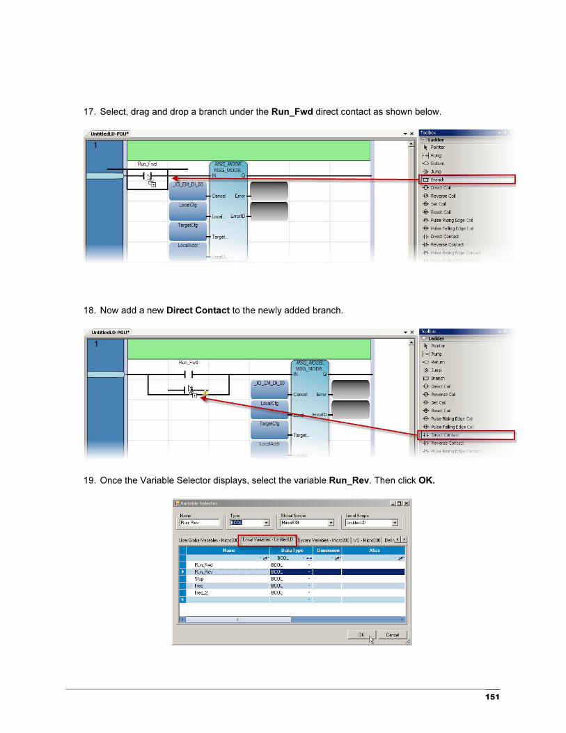
17. Select, drag and drop a branch under the Run_Fwd direct contact as shown below.
18. Now add a new Direct Contact to the newly added branch.
19. Once the Variable Selector displays, select the variable Run_Rev. Then click OK.

152
20. Repeat steps 18 and 19 for Stop, Freq, and Freq_2 branches.
21. Your ladder is now complete and it should look like this:

153
22. Now you are ready to start debugging. Save, build and download your project. Click on the
button on the top menu bar. Trigger input 4 (_IO_EM_DI_04) to write pre-set frequency 1 (Freq).
23. Now that a frequency is set, trigger input 1 (_IO_EM_DI_01) to enable the forward command in
the drive as shown below. This verifies the message is working as intended feel free to toggle the
other bits to test Stop, Run_Rev, and Freq_2.

154
Appendix A
1Gain
Description:
Directly links the input to output. When used with a Boolean negation, moves a copy of i1 to o1 .
Arguments:
Parameter Parameter Type Data Type Description
EN Input BOOL Function enable.
When EN = TRUE, execute the direct link to an
output computation.
When EN = FALSE, there is no computation.
i1 Input BOOL - DINT -
REAL - TIME -
STRING - SINT -
USINT - INT -
UINT - UDINT -
LINT - ULINT -
DATE - LREAL -
BYTE - WORD -
DWORD -
LWORD
Input and output must use the same format.
o1 Output BOOL - DINT -
REAL - TIME -
STRING - SINT -
USINT - INT -
UINT - UDINT -
LINT - ULINT -
DATE - LREAL -
BYTE - WORD -
DWORD -
LWORD
Input and output must use the same format.
ENO Output BOOL Enable out.
155

156

157
Chapter 7 – Using Connected Components Workbench with Temperature Controllers
158
Hardware & Software Versions Used
• Temperature Controller, 900-TC8 or 900-TC16
• Simple Temperature Control Connected Component Building Block, Pub# CC-QS005A-EN-P
• Appropriate communication module for the 900-TC per application
o 900-TC8COM
o 900-TC16NACCOM

159
Configuring and Programming the Controller for Modbus
Communications to a 900-TC Temperature Controller
This chapter will show you how to configure and program the Micro830 controller with the 2080-SERIALISOL and the 900-TC termperature controller.
1. With the assumption you have the Micro830 controller selected in the project file, you can now go
to the controller window and select the 2080-SERIALISOL plug-in card. For more information on
how to create a new Micro830 project, review the Getting Started Guide (Pub# 2080-QR001B-
EN-P).
160
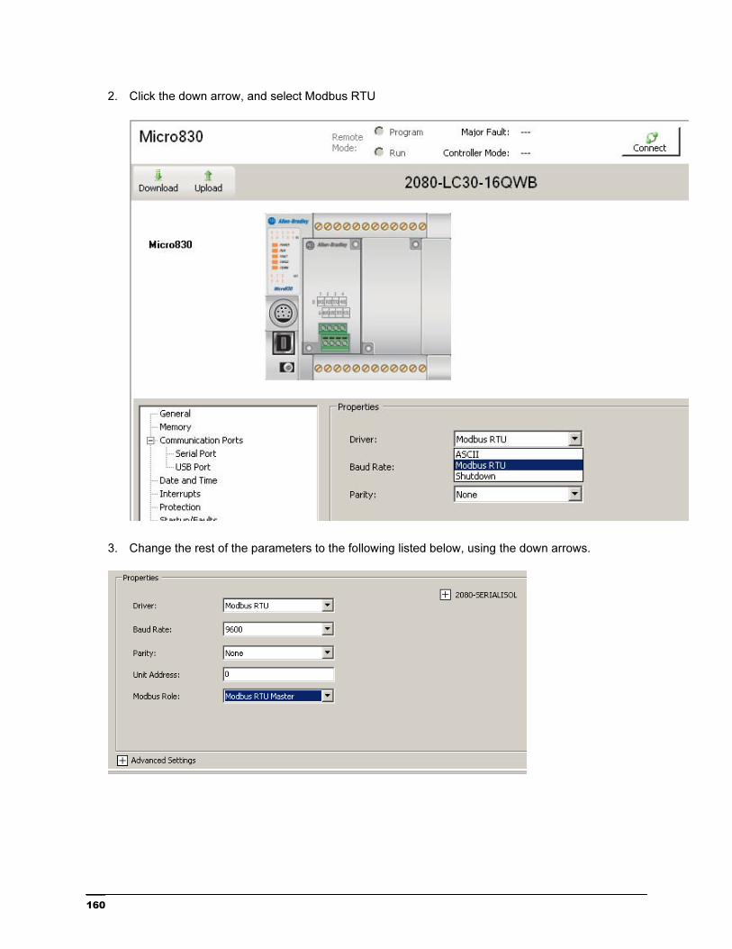
2. Click the down arrow, and select Modbus RTU
3. Change the rest of the parameters to the following listed below, using the down arrows.

161
4. Expand the Advanced Settings and change the Media to RS485. Leave the rest of the
parameters as shown below.
5. Right click on Micro830, then select Build.

162
6. Right click on programs. Move the cursor over the Add tab, to New LD: Ladder Diagram.
The following will now appear.
7. Double click the ladder icon.

163
8. Open the Toolbox tab if it is not open.
164
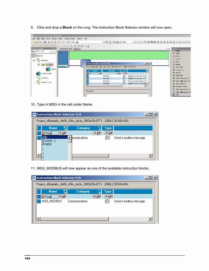
9. Click and drop a Block on the rung. The Instruction Block Selector window will now open.
10. Type in MSG in the cell under Name.
11. MSG_MODBUS will now appear as one of the available instruction blocks.

165
12. Double click on MSG_MODBUS and the following will appear.

166
13. To use the block, you need to configure it. To find help on the instruction blocks, in this case the
MSG Modbus, go to Help, Search, click on Local Help, and enter MSG Modbus in the search
box.

167
14. Here you will find the information on the inputs and outputs of the block.
15. For the Cancel parameter, click on the upper part of the blue box and double click on the input
from the Micro830 you want to use, in this case, Input 0.

168
16. To create the other variables for the function block, double click on the bottom of the next blue
box and open up the Local Variables.
17. We now need to create variables for use with the function blocks. Click on the light blue box to
the right of the asterick. Type in LocalCfg. Tab over to Data Type.
18. Type in MODBUSLOCPARA. See step 15 for where this data type assignment came from. You
will note as you begin typing, the name will populate. Pay attention to the last half of the word to
ensure you have the correct data type. Hit enter.
169
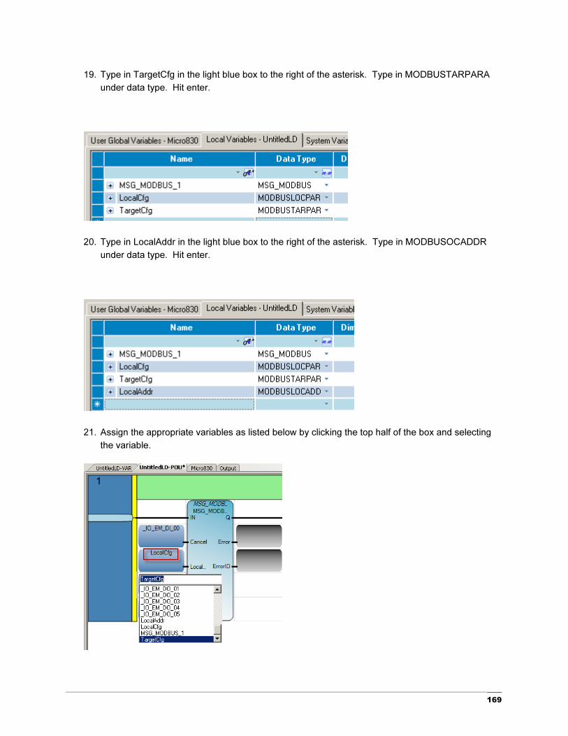
19. Type in TargetCfg in the light blue box to the right of the asterisk. Type in MODBUSTARPARA
under data type. Hit enter.
20. Type in LocalAddr in the light blue box to the right of the asterisk. Type in MODBUSOCADDR
under data type. Hit enter.
21. Assign the appropriate variables as listed below by clicking the top half of the box and selecting
the variable.
170
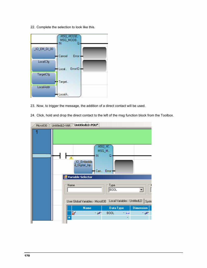
22. Complete the selection to look like this.
23. Now, to trigger the message, the addition of a direct contact will be used.
24. Click, hold and drop the direct contact to the left of the msg function block from the Toolbox.
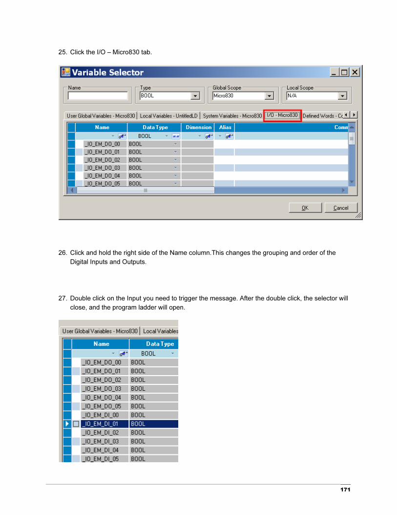
171
25. Click the I/O – Micro830 tab.
26. Click and hold the right side of the Name column.This changes the grouping and order of the
Digital Inputs and Outputs.
27. Double click on the Input you need to trigger the message. After the double click, the selector will
close, and the program ladder will open.

172
28. Set up the parameters as shown below by clicking on the Initial Value box for each variable. You
may have to use the scroll bar at the bottom of the variable tab to see the Initial Value column.
For ease of use, you can move the Initial Value column by click and holding the top of the
column and moving the column to where you want it. These settings are based on the 900-TC
settings used and found in Publication CC-QS005A-EN-P. Information on the message variables
can be found in the CCW Help.
29. Build and download the program.
173
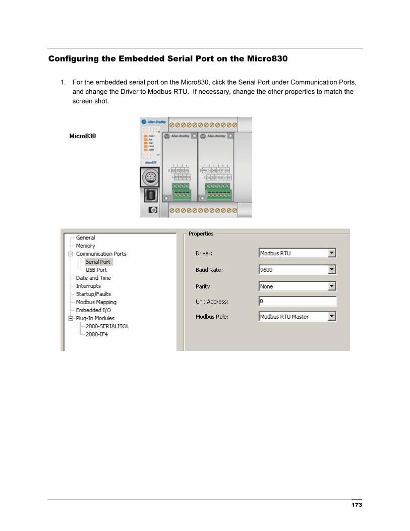
Configuring the Embedded Serial Port on the Micro830
1. For the embedded serial port on the Micro830, click the Serial Port under Communication Ports,
and change the Driver to Modbus RTU. If necessary, change the other properties to match the
screen shot.

174
2. Open the Advanced settings and select RS485 for Media.
3. Go to the variables window and change the LocalCfg Channel to 2.
4. Build the project.

175
Cabling the Controller for a 900-TC Temperature Controller and Testing
the Controller Program.
This section will show you how to configure and program the Micro830 controller with the 2080-SERIALISOL and the 900-TC temperature controller.
1. For this section, program the 900-TC as listed in the Simple Temperature Control Connected
Components Building Block, Publication CC-QS005A and Temperature Controllers User Manual,
Publication 900-UM007D.
Follow the steps below for the 900-TC communication setup:

176
2. Follow the basic wiring connections shown below, select the appropriate drawings based on the
900-TC you are using. When using the 2080 SERIALISOL module, ground the shield/drain to the
chassis of the controller.

177
Note: If using the 1763-NC01 cable, wire the same for the 900-TC, connect the following way.

178
Note: Grounding Your Analog Cable
Use shielded communication cable, such as the Belden #3105A. The Belden #3105A cable has
two signal wires (White/Blue Stripe and Blue/White Stripe), one drain wire, and a foil shield.
The drain wire and foil shield must be grounded at end of cable.
3. Assuming you have created the program from the previous sections starting in Chapter 7, built
and downloaded the program on the Micro830, you can now proceed.

179
4. Verify the program by running the debugger.
5. View the variable tab. Energize input 1 on the Micro830. You should get something similar to
this. LocalAddr(2) is the process variable, LocalAddr(3) is the lower status word, LocalAddr(4) is
the upper status word, and LocalAddr(6) is the set point.

180