2023 Standard Efficiency Gas/Electric Direct-Drive ...
32
SS-DFC5-D www.daikinac.com 11/21 DFC Commercial * Complete warranty details available from your local distributor or manufacturer’s representave or at www.daikincomfort.com or www.daikinac.com 2023 Standard Efficiency Air Conditioner Direct-Drive Packaged Rooftop Unit 5 Ton DFC Light Commercial 13.4 SEER2/11 EER2 14 SEER/11.5 EER
Transcript of 2023 Standard Efficiency Gas/Electric Direct-Drive ...

SS-DFC5-D www.daikinac.com 11/21
DFC Commercial
* Complete warranty details available from your local distributor or manufacturer’s representative or at www.daikincomfort.com or www.daikinac.com
2023 Standard Efficiency Air Conditioner Direct-Drive Packaged Rooftop Unit
5 Ton DFC Light Commercial13.4 SEER2/11 EER2
14 SEER/11.5 EER

Our Perfect Package:Harnessing energy-efficient performance, proven technology, and enhanced comfort for life.
Since becoming the first company in Japan to manufacture packaged
air conditioning systems, in 1951, Daikin has supported comfortable
indoor living based on the strengths and technologies that have
led to the growth of the company becoming one of the
world’s largest manufacturers of HVAC products, systems
and refrigerants.
Today, as a comprehensive global manufacturer of HVAC products
and systems, the Daikin brand is committed to being recognized
as a truly global and excellent company capable of continually
creating new value for its customers. The company plans to pursue
sustainable growth and foster business operations that consistently
harmonize with the goals of improving indoor comfort.
The group philosophy of the company includes: » Creating new value continuously for customers
» Developing world leading energy-saving technology
» Being a flexible and dynamic organization
» Allowing employees to be the driving force for the success of the company
» Fostering an atmosphere of best practices, boldness, and innovation
» Thinking and acting globally

3
Contents2 Introduction 2
4 Nomenclature 4
5 Features and Benefits 5
Applications 8Serviceability 8
9 Product Specifications 9
Coil Dimensions 9AHRI Ratings 9Sound Data 9
10 Expanding Cooling Data 10
12 Electric Heater Data 12
13 Air Flow 13
19 Static Pressure 19
20 Electrical Data 20
23 Wiring Diagrams 23
26 Dimensional Data 26
27 Electrical Connections 27
Unit Clearances 27
28 Installation 28
Weights 28
29 Accessories 29
31 Factory Installed Options 31
31 Field Installed Options 31
32 Factory and Field Installed Options 32

Nomenclature
4 www.daikinac.com SS-DFC5-D
D F C 300 3 S 400 C A A
1 2 3 4,5,6 7 8 9,10,11 12 13 14
BrandD Daikin
ConfigurationF 2023 Standard Efficiency
ApplicationC CoolingG Gas Heat
Nominal Cooling Capacity060 5 Tons
Voltage1 208-230/1/60 4 460/3/603 208-230/3/60 7 575/3/60
Supply Fan/Drive Type/MotorD Direct-Drive - Standard Static W Direct Drive - High Static
Nominal Heating CapacityGas/Electric A/C H/P Factory-Installed Electric Heat090 90,000 BTU/h XXX No Heat115 115,000 BTU/h 006 5kW140 140,000 BTU/h 011 10 kW
017 15 kW023 20 kW
See product specifications for heat size(s) available for each capacity.
Refrigeration SystemsA Single-stage cooling modes
Heat Exchanger
X No optionsA Standard Aluminized ExchangerS Stainless Steel Exchanger
ControlsA Electromechanical controls
X X X X X X X X A *
15 16 17 18 19 20 21 22 23 24
Revision Levels
Major & Minor
PE Connection
X No OptionsB Single-point power connection for Power Exhaust
IAQ
X No Options
Service OptionsX No OptionA Powered convenience outletB Non-powered convenience outletC Hinge PanelsD Hinged Panels and Powered convenience outletE Hinged Panels and non-powered convenience outlet
ElectricalX No OptionsA Non-Fused DisconnectB Phase MonitorC Thru-the-base connectionsE Non-Fused Disconnect and Phase MonitorF Non-Fused Disconnect and Thru-the-base connectionsH Phase Monitor and Thru-the-base connectionsL Non-Fused Disconnect, Thru-the-base connections and Phase Monitor
EconomizerX No OptionsA Ultra Low-Leak Downflow Economizer w/Enthalpy SensorB Low-Leak Downflow Economizer w/Enthalpy SensorG Ultra Low-Leak Downflow Economizer w/Dry Bulb SensorH Low-Leak Downflow Economizer w/Dry Bulb Sensor
Coils, Hail guard
X No OptionsA E-coat outdoor
C Hail GuardD E-coat outdoor w/ Hail Guard
SensorsX No OptionsA RA Smoke DetectorB SA Smoke DetectorC RA & SA Smoke Detector
AC Stocking ModelsNew Daikin 5 Ton Direct Drive
Model Number CodestringDFC0601D000001S DFC0601DXXXAXAXXXXXXXXDFC0603D000001S DFC0603DXXXAXAXXXXXXXXDFC0604D000001S DFC0604DXXXAXAXXXXXXXXDFC0607D000001S DFC0607DXXXAXAXXXXXXXX
Features and Benefits
SS-DFC5-D www.daikinac.com 5
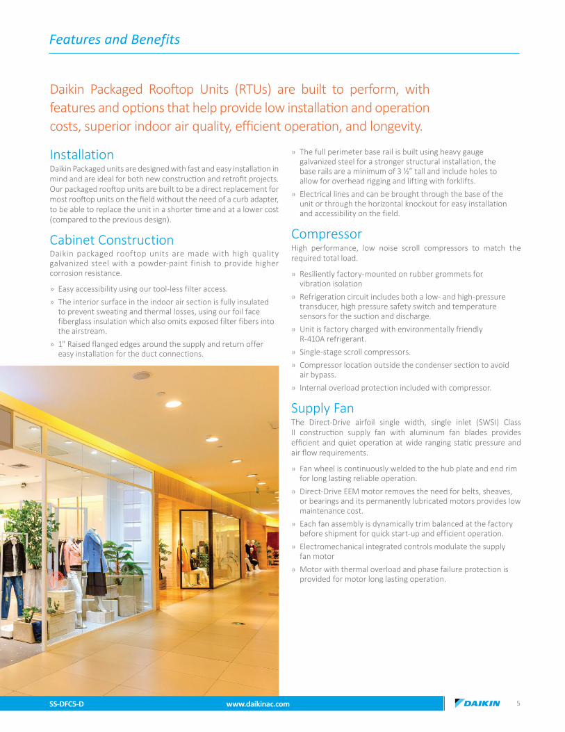
Installation Daikin Packaged units are designed with fast and easy installation in mind and are ideal for both new construction and retrofit projects. Our packaged rooftop units are built to be a direct replacement for most rooftop units on the field without the need of a curb adapter, to be able to replace the unit in a shorter time and at a lower cost (compared to the previous design).
Cabinet Construction Daikin packaged rooftop units are made with high quality galvanized steel with a powder-paint finish to provide higher corrosion resistance.
» Easy accessibility using our tool-less filter access.
» The interior surface in the indoor air section is fully insulated to prevent sweating and thermal losses, using our foil face fiberglass insulation which also omits exposed filter fibers into the airstream.
» 1" Raised flanged edges around the supply and return offer easy installation for the duct connections.
» The full perimeter base rail is built using heavy gauge galvanized steel for a stronger structural installation, the base rails are a minimum of 3 ½” tall and include holes to allow for overhead rigging and lifting with forklifts.
» Electrical lines and can be brought through the base of the unit or through the horizontal knockout for easy installation and accessibility on the field.
Compressor High performance, low noise scroll compressors to match the required total load.
» Resiliently factory-mounted on rubber grommets for vibration isolation
» Refrigeration circuit includes both a low- and high-pressure transducer, high pressure safety switch and temperature sensors for the suction and discharge.
» Unit is factory charged with environmentally friendly R-410A refrigerant.
» Single-stage scroll compressors.
» Compressor location outside the condenser section to avoid air bypass.
» Internal overload protection included with compressor.
Supply Fan The Direct-Drive airfoil single width, single inlet (SWSI) Class II construction supply fan with aluminum fan blades provides efficient and quiet operation at wide ranging static pressure and air flow requirements.
» Fan wheel is continuously welded to the hub plate and end rim for long lasting reliable operation.
» Direct-Drive EEM motor removes the need for belts, sheaves, or bearings and its permanently lubricated motors provides low maintenance cost.
» Each fan assembly is dynamically trim balanced at the factory before shipment for quick start-up and efficient operation.
» Electromechanical integrated controls modulate the supply fan motor
» Motor with thermal overload and phase failure protection is provided for motor long lasting operation.
Daikin Packaged Rooftop Units (RTUs) are built to perform, with features and options that help provide low installation and operation costs, superior indoor air quality, efficient operation, and longevity.

Features and Benefits
DBC3
6 www.daikinac.com SS-DFC5-D
Coils The indoor coil section is installed in a draw through configuration to provide better dehumidification. These coils are constructed with seamless copper tubes, mechanically bonded into aluminum plate-type fins with full drawn collars to completely cover the tubes for high operating efficiencies.
» Coils are factory pressure tested to ensure pressure and leak integrity.
» Copper tube / aluminum fin coils on evaporator
» All units use large face area outdoor coils
» Microchannel heat exchanger on condenser coils technology on all condenser coils for improved performance and reduced refrigerant load.
Controls and Wiring Packaged rooftop units come equipped with a well-organized, large, easy to use weatherproof internal control box with easy access, for a better user experience.
» Units are factory-wired with labeled color-coded wires and complete 24-volt Electromechanical controls package.
» Units include single-point power entry as standard and also available with electric heat kits if selected.
» Terminal blocks are provided as standard for easy installation and field power wiring
Filtration Unit provides a draw-through filter section as standard for better air quality and long lasting component maintenance.
» Filters installed on the units are standard off the shelf sizes for easy replacement.
» One or two size filter per unit for low maintenance cost and easy replacement.
» Easy and fast filter service access.
Heating Section Wide ranging of electric heat selections effectively handle most comfort heating demand from morning warm-up control to full heat.
Electric Heat ETL approved electric heat is factory assembled, installed and tested.
» Heating control is fully integrated into the unit’s control system for quick start-up and reliable control.
» Durable low watt density, nickel chromium elements provide longer life (compared to units without).
» Fuses are provided in each branch circuit to a maximum of 48 Amps per NEC requirements.
» Single-point power connection reduces installation cost.
» For operational safeties electric heat includes automatic reset, and high temperature limit safety protection and an airflow safety switch to prevent electric heat operation in the event of no airflow.
Electrical Units are completely wired and tested at the factory to provide faster commissioning and start-up.
» Wiring complies with NEC requirements and all applicable UL standards.
» For ease of use, wiring and electrical components are number coded and labeled according to the electrical diagram.
» A 120 V GFI convenience receptacle requiring independent power supply for the receptacle is optional.
» An optional unit powered 20 amp 115 V convenience receptacle, complete with factory mounted transformer, disconnect switch, and primary and secondary overload protection, eliminates the need to pull a separate 115 V power source.
» Supply air fan, compressor, and condenser fan motor branch circuits have individual short circuit protection. Unit includes knockouts in the bottom of the main control panels for field wiring entrance.
» A single-point power connection with power block is standard and a terminal board is provided for connecting low voltage control wiring.
» For better serviceability an optional non-fused disconnect switch can be installed inside the control panel and operated by an externally mounted handle to disconnect the electrical power at the unit


Applications & Serviceability
8 www.daikinac.com SS-DFC5-D
ApplicationsDaikin Rooftop units are intended for comfort cooling applications in normal heating, ventilating, and air conditioning. Consult your local Daikin sales representative for applications involving operations at high ambient temperatures, high altitudes, non-cataloged voltages, or for job-specific unit selections that fall outside of the range of the catalog tables.
For proper operation, units should be rigged in accordance with instructions stated on the installation manual. Fire dampers, if required, must be installed in the ductwork according to local and/or state codes. No space is allowed for these dampers in the unit.
Follow factory check, test and start procedures explicitly to achieve satisfactory start-up and operation.
Most rooftop applications take advantage of the significant energy savings provided with economizer operation. When an economizer system is used, mechanical refrigeration is typically not required below an ambient temperature of 50°F.
Serviceability Daikin packaged rooftop units are built with serviceability in mind, designed to make future maintenance and service on the unit easy and accessible.
» Our packaged rooftop units offer a slide out blower to facilitate the access and removal of the fan.
» Filter panels on the small chassis line offer tool-less access for easy maintenance.
» Independent compressor outside of the air bypass to eliminate component blockage and provide easy access.
» Labeled field connections, color coded and continuously marked wire to identify point-to-point component connections.
» All 5 ton units are designed for convertible airflow orientation to serve downflow or horizontal applications. Every unit ships prepared to convert to horizontal orientation in the field if required.
» Condenser clean out from inside-out.
» Easy access to gas valves and control panel.

Product Specifications
SS-DFC5-D www.daikinac.com 9
Model DFC0601D000001S DFC0603D000001S DFC0604D000001S DFC0607D000001SCOOLING CAPACITYTotal, BTU/h 59,000 59,000 59,000 59,000SEER / EER N/A 14/11.5 14/11.5 14/11.5SEER2 / EER2 13.4/11.0 13.4/11.0 13.4/11.0 13.4/11.0AHRI Reference # 207516914 207516918 207516919 207516920EVAPORATOR MOTOR / COIL Motor Type Direct Drive Direct Drive Direct Drive Direct DriveExternal Static Pressure (ESP) Standard Standard Standard Standard Wheel Dia. X Width 12 x 11 12 x 11 12 x 11 12 x 11Indoor Nominal CFM 1820 1820 1820 1820RPM 1200/VAR 1200/VAR 300-1500 300-1500Indoor Horsepower 1.0 1.0 1.2 1.2Filter Size (in) 20 X 25 X 2 (2) 20 X 25 X 2 (2) 20 X 25 X 2 (2) 20 X 25 X 2 (2)Drain Size (NPT) ¾ ¾ ¾ ¾R-410A Refrigerant Charge (oz.) 82 82 82 82Evaporator Coil Face Area (ft²) 6.4 6.4 6.4 6.4Rows Deep/ Fins per Inch �⁄16 �⁄16 �⁄16 �⁄16 CONDENSER FAN/COILQuantity of Condenser Fan Motors 1 1 1 1RPM (High/Low stage) 1122 1122 1050 1050Outdoor Horsepower 1/3 1/3 1/3 1/3Fan Diameter/ # Fan Blades 22 / 3 22 / 3 22 / 3 22 / 3Face Area (ft²) 17.6 17.6 17.6 17.6Rows Deep / Fins per Inch �⁄23 �⁄23 1 / 23 �⁄23
COMPRESSOR (ALL SINGLE-STAGE)Quantity / Type / Stages 1 / Scroll / 1 1 / Scroll / 1 1 / Scroll / 1 1 / Scroll / 1Compressor RLA / LRA 26.4 / 134.0 16.0 / 110.0 7.8 / 52.0 5.7 / 38.9ELECTRICAL DATA Voltage-Phase-Frequency 208/230-1-60 208/230-3-60 460-3-60 575-3-60Indoor Blower FLA 6.9 6.9 2.5 2.0Max External Static (In. W.C.) 0.8 0.8 0.8 0.8Outdoor Fan FLA 2.0 2.0 0.85 0.67Min. Circuit Ampacity¹ 41.9 / 41.9 28.9 / 28.9 13 9.8Max. Overcurrent Protection (A)² 60 / 60 40 / 40 20 15Power Supply Conduit Hole Dia. (in) 1.125 1.125 1.125 1.125Low-Voltage Conduit Hole Dia. (in) 0.5 0.5 0.5 0.5OPERATING WEIGHT (LBS.)Operating Weight (lbs) 512 508 512 512SHIPPING WEIGHT (LBS.)Ship Weight (lbs) 582 578 582 582¹ Wire size should be determined in accordance with National Electrical Codes. Extensive wire runs will require larger wire sizes. ² May use fuses or HACR-type circuit breakers of the same size as noted. Note: Always check the S&R plate for electrical data on the unit being installed.
DFC060
MODEL CAPACITY EER2 SEER2 EER SEERDFC0601D 59,000 11.0 13.4 11.5 14DFC0603D 59,000 11.0 13.4 11.5 14DFC0604D 59,000 11.0 13.4 11.5 14DFC0607D 59,000 11.0 13.4 11.5 14
AHRI Ratings Sound DataModel
Outdoor sound (db) at 60 HzA-Weighted 125 250 500 1000 2000 4000 8000 8000
060 77 63.1 66.7 70.3 72.8 70.0 65.1 59.2 59.2Notes:
1 Outdoor sound data is measured in accordance with AHRI standard 270. 2 Measurements are expressed in terms of sound power. Do not compare these values to sound pressure values because sound pressure depends on specific environment factors which normally do not match individual applications. Sound power values are independent of the environment and therefore more accurate.3 A-weighted sound ratings filter out high and very low frequencies, to better approximate the response of "average" human ear. A-weighted measurements for Daikin units are taken in accordance with AHRI standard 270.
Model Tons Fin height in. Fin length in.DFC 5 24.25 38.07
Coil Dimensions

Expanded Cooling Data
10 www.daikinac.com SS-DFC5-D
DFC060O
utdo
or A
mbi
ent T
empe
ratu
re
6575
8595
105
115
Ente
ring
Indo
or W
et B
ulb
Tem
pera
ture
IDB
Air
flow
ID W
B59
6367
7159
6367
7159
6367
7159
6367
7159
6367
7159
6367
71
70
1500
Capa
city
59,7
4260
,590
62,3
83-
59,2
0560
,053
61,8
46-
57,6
3758
,485
60,2
78-
54,9
4155
,789
57,5
82-
51,6
4552
,493
54,2
86-
48,6
3649
,484
51,2
77-
S/T
0.56
0.48
0.35
-0.
560.
490.
36-
0.59
0.51
0.38
-0.
610.
530.
40-
0.63
0.55
0.42
-1.
000.
600.
47-
Evap
dT
20.2
318
.41
15.0
0-
20.1
818
.36
14.9
5-
20.4
418
.61
15.2
1-
20.1
618
.34
14.9
4-
19.9
218
.09
14.6
9-
21.0
619
.24
15.8
3-
Pr S
uc11
811
912
2-
125
126
129
-13
113
313
6-
136
138
141
-14
214
314
6-
148
150
153
-
Pr D
is26
326
426
6-
305
306
308
-34
935
035
2-
396
397
399
-44
744
845
0-
501
502
504
-
Tota
lPow
er3,
650
3,64
73,
639
-4,
085
4,08
14,
074
-4,
570
4,56
64,
559
-5,
094
5,09
15,
084
-5,
681
5,67
75,
670
-6,
369
6,36
56,
358
-
1820
Capa
city
60,8
1461
,662
63,4
55-
60,2
7761
,125
62,9
18-
58,7
1059
,557
61,3
50-
56,0
1356
,861
58,6
54-
52,7
1753
,565
55,3
58-
49,7
0850
,556
52,3
49-
S/T
0.65
0.57
0.44
-0.
650.
580.
45-
0.68
0.60
0.47
-0.
700.
620.
49-
1.00
0.64
0.51
-1.
000.
690.
56-
Evap
dT
18.6
116
.78
13.3
8-
18.5
616
.74
13.3
3-
18.8
116
.99
13.5
9-
18.5
416
.72
13.3
1-
18.3
016
.47
13.0
7-
19.4
417
.61
14.2
1-
Pr S
uc12
012
112
4-
127
129
132
-13
313
513
8-
139
140
143
-14
414
614
9-
151
152
155
-
Pr D
is26
726
827
0-
308
309
311
-35
235
335
5-
399
400
402
-45
045
145
3-
504
505
507
-
Tota
lPow
er3,
683
3,68
03,
672
-4,
118
4,11
44,
107
-4,
603
4,59
94,
592
-5,
128
5,12
45,
117
-5,
714
5,71
15,
703
-6,
402
6,39
86,
391
-
2250
Capa
city
62,7
6463
,611
65,4
05-
62,2
2663
,074
64,8
67-
60,6
5961
,507
63,3
00-
57,9
6258
,810
60,6
03-
54,6
6655
,514
57,3
07-
51,6
5852
,505
54,2
99-
S/T
0.69
0.62
0.49
-0.
700.
620.
49-
0.72
0.65
0.52
-0.
740.
670.
53-
1.00
0.69
0.56
-1.
000.
740.
61-
Evap
dT
16.9
515
.12
11.7
2-
16.9
015
.07
11.6
7-
17.1
515
.33
11.9
3-
16.8
815
.05
11.6
5-
16.6
314
.81
11.4
1-
17.7
715
.95
12.5
5-
Pr S
uc12
412
512
8-
131
133
136
-13
713
914
2-
143
144
147
-14
814
915
2-
154
156
159
-
Pr D
is27
127
227
4-
312
314
315
-35
635
735
9-
403
404
406
-45
445
545
7-
508
509
511
-
Tota
lPow
er3,
717
3,71
43,
706
-4,
152
4,14
84,
141
-4,
637
4,63
34,
626
-5,
161
5,15
85,
151
-5,
748
5,74
45,
737
-6,
436
6,43
26,
425
-
75
1500
Capa
city
59,7
7760
,625
62,4
1865
,157
59,2
4060
,088
61,8
8164
,620
57,6
7258
,520
60,3
1363
,052
54,9
7655
,823
57,6
1760
,356
51,6
8052
,528
54,3
2157
,060
48,6
7149
,519
51,3
1254
,051
S/T
0.68
0.61
0.48
0.34
0.69
0.61
0.48
0.34
0.71
0.64
0.51
0.37
1.00
0.66
0.53
0.39
1.00
0.68
0.55
0.41
1.00
0.73
0.60
0.46
Evap
dT
24.2
422
.41
19.0
115
.49
24.1
922
.36
18.9
615
.44
24.4
422
.62
19.2
215
.69
24.1
722
.35
18.9
415
.42
23.9
322
.10
18.7
015
.17
25.0
723
.24
19.8
416
.31
Pr S
uc11
811
912
212
712
512
612
913
413
113
313
614
113
613
814
114
614
214
314
615
114
815
015
315
8
Pr D
is26
426
526
727
130
530
630
831
334
935
035
235
739
639
739
940
444
744
845
045
450
150
250
450
8
Tota
lPow
er3,
647
3,64
43,
636
3,67
04,
082
4,07
84,
071
4,10
44,
567
4,56
34,
556
4,58
95,
092
5,08
85,
081
5,11
45,
678
5,67
55,
667
5,70
06,
366
6,36
26,
355
6,38
8
1820
Capa
city
60,8
4961
,697
63,4
9066
,229
60,3
1261
,160
62,9
5365
,692
58,7
4459
,592
61,3
8564
,124
56,0
4856
,896
58,6
8961
,428
52,7
5253
,600
55,3
9358
,132
49,7
4350
,591
52,3
8455
,123
S/T
0.77
0.70
0.57
0.43
0.78
0.70
0.57
0.43
1.00
0.73
0.60
0.46
1.00
0.75
0.62
0.48
1.00
0.77
0.64
0.50
1.00
0.82
0.69
0.55
Evap
dT
22.6
220
.79
17.3
913
.86
22.5
720
.74
17.3
413
.81
22.8
221
.00
17.6
014
.07
22.5
520
.72
17.3
213
.79
22.3
020
.48
17.0
813
.55
23.4
421
.62
18.2
214
.69
Pr S
uc12
012
112
413
012
712
913
213
713
413
513
814
313
914
014
314
814
414
614
915
415
115
215
516
0
Pr D
is26
726
827
027
430
831
031
131
635
235
335
536
039
940
040
240
745
045
145
345
850
450
550
751
2
Tota
lPow
er3,
681
3,67
73,
670
3,70
34,
115
4,11
24,
104
4,13
74,
600
4,59
74,
589
4,62
25,
125
5,12
15,
114
5,14
75,
711
5,70
85,
700
5,73
46,
399
6,39
66,
388
6,42
1
2250
Capa
city
62,7
9963
,646
65,4
4068
,179
62,2
6163
,109
64,9
0267
,641
60,6
9461
,542
63,3
3566
,074
57,9
9758
,845
60,6
3863
,377
54,7
0155
,549
57,3
4260
,081
51,6
9352
,540
54,3
3457
,073
S/T
0.82
0.74
0.61
0.47
0.82
0.75
0.62
0.48
1.00
0.77
0.64
0.50
1.00
0.79
0.66
0.52
1.00
0.81
0.68
0.54
1.00
1.00
0.73
0.59
Evap
dT
20.9
519
.13
15.7
312
.20
20.9
019
.08
15.6
812
.15
21.1
619
.34
15.9
312
.41
20.8
819
.06
15.6
612
.13
20.6
418
.82
15.4
111
.89
21.7
819
.96
16.5
613
.03
Pr S
uc12
412
512
813
313
113
313
614
113
713
914
214
714
314
414
715
214
814
915
215
715
415
615
916
4
Pr D
is27
127
227
427
931
331
431
632
035
635
735
936
440
340
540
641
145
445
545
746
250
850
951
151
6
Tota
lPow
er3,
714
3,71
13,
703
3,73
74,
149
4,14
54,
138
4,17
14,
634
4,63
04,
623
4,65
65,
159
5,15
55,
148
5,18
15,
745
5,74
25,
734
5,76
76,
433
6,42
96,
422
6,45
5
IDB:
Ent
erin
g In
door
Dry
Bul
b Te
mpe
ratu
reSh
aded
are
a re
flect
s AC
CA (T
VA) c
ondi
tions
W =
Tot
al s
yste
m p
ower
Hig
h an
d lo
w p
ress
ures
are
mea
sure
d at
the
liqui
d an
d su
ctio
n ac
cess
fitt
ings
.A
mps
: Uni
t am
ps (c
omp.
+ ev
apor
ator
+ c
onde
nser
fan
mot
ors)
Des
ign
Subc
oolin
g, 1
6 - 1
9 °F
@ th
e liq
uid
acce
ss fi
ttin
g co
nnec
tion
ARI
95
test
con
ditio
ns. D
esig
n Su
perh
eat 8
- 12
°F @
the
com
pres
sor s
uctio
n ac
cess
fitt
ing
conn
ectio
n.

Expanded Cooling Data
SS-DFC5-D www.daikinac.com 11
DFC060 (cont.)O
utdo
or A
mbi
ent T
empe
ratu
re
6575
8595
105
115
Ente
ring
Indo
or W
et B
ulb
Tem
pera
ture
IDB
Air
flow
ID W
B59
6367
7159
6367
7159
6367
7159
6367
7159
6367
7159
6367
71
80
1500
Capa
city
60,0
8860
,936
62,7
2965
,468
59,5
5160
,399
62,1
9264
,931
57,9
8358
,831
60,6
2463
,363
55,2
8756
,134
57,9
2860
,667
51,9
9152
,839
54,6
3257
,371
48,9
8249
,830
51,6
2354
,362
S/T
0.80
0.73
0.60
0.46
1.00
0.74
0.60
0.47
1.00
0.76
0.63
0.49
1.00
0.78
0.65
0.51
1.00
0.80
0.67
0.53
1.00
1.00
0.72
0.58
Evap
dT
28.2
726
.45
23.0
519
.52
28.2
226
.40
23.0
019
.47
28.4
826
.66
23.2
519
.73
28.2
026
.38
22.9
819
.45
27.9
626
.14
22.7
319
.21
29.1
027
.28
23.8
820
.35
Pr S
uc11
812
012
312
812
512
713
013
513
213
313
614
113
713
814
114
614
214
414
715
214
915
015
315
8
Pr D
is26
426
526
727
230
630
730
931
334
935
135
235
739
739
840
040
444
744
845
045
550
150
350
450
9
Tota
lPow
er3,
650
3,64
63,
639
3,67
24,
084
4,08
14,
073
4,10
64,
569
4,56
64,
558
4,59
15,
094
5,09
05,
083
5,11
65,
680
5,67
75,
669
5,70
36,
368
6,36
56,
357
6,39
1
1820
Capa
city
61,1
6062
,008
63,8
0166
,540
60,6
2361
,471
63,2
6466
,003
59,0
5559
,903
61,6
9664
,435
56,3
5957
,207
59,0
0061
,739
53,0
6353
,911
55,7
0458
,443
50,0
5450
,902
52,6
9555
,434
S/T
0.89
0.82
0.69
0.55
1.00
0.83
0.69
0.56
1.00
0.85
0.72
0.58
1.00
0.87
0.74
0.60
1.00
1.00
0.76
0.62
1.00
1.00
0.81
0.67
Evap
dT
26.6
524
.83
21.4
217
.90
26.6
024
.78
21.3
717
.85
26.8
625
.03
21.6
318
.10
26.5
824
.76
21.3
617
.83
26.3
424
.52
21.1
117
.59
27.4
825
.66
22.2
518
.73
Pr S
uc12
112
212
513
012
812
913
213
713
413
513
914
413
914
114
414
914
514
614
915
415
115
315
616
1
Pr D
is26
726
827
027
530
931
031
231
735
335
435
636
040
040
140
340
745
045
245
345
850
550
650
851
2
Tota
lPow
er3,
683
3,67
93,
672
3,70
54,
117
4,11
44,
106
4,14
04,
602
4,59
94,
591
4,62
55,
127
5,12
45,
116
5,14
95,
713
5,71
05,
703
5,73
66,
401
6,39
86,
391
6,42
4
2250
Capa
city
63,1
1063
,957
65,7
5168
,490
62,5
7263
,420
65,2
1367
,952
61,0
0561
,853
63,6
4666
,385
58,3
0859
,156
60,9
4963
,688
55,0
1255
,860
57,6
5360
,392
52,0
0452
,851
54,6
4557
,384
S/T
1.00
0.86
0.73
0.59
1.00
0.87
0.74
0.60
1.00
0.89
0.76
0.62
1.00
0.91
0.78
0.64
1.00
1.00
0.80
0.66
1.00
1.00
0.85
0.71
Evap
dT
24.9
923
.16
19.7
616
.24
24.9
423
.12
19.7
116
.19
25.1
923
.37
19.9
716
.44
24.9
223
.10
19.6
916
.17
24.6
822
.85
19.4
515
.92
25.8
223
.99
20.5
917
.07
Pr S
uc12
412
612
913
413
213
313
614
113
813
914
214
714
314
514
815
314
815
015
315
815
515
615
916
5
Pr D
is27
127
327
427
931
331
431
632
135
735
836
036
440
440
540
741
145
545
645
846
250
951
051
251
6
Tota
lPow
er3,
717
3,71
33,
706
3,73
94,
151
4,14
84,
140
4,17
34,
636
4,63
34,
625
4,65
85,
161
5,15
75,
150
5,18
35,
747
5,74
45,
736
5,77
06,
435
6,43
26,
424
6,45
8
85
1500
Capa
city
61,1
0061
,947
63,7
4066
,479
60,5
6261
,410
63,2
0365
,942
58,9
9559
,843
61,6
3664
,375
56,2
9857
,146
58,9
3961
,678
53,0
0253
,850
55,6
4358
,382
49,9
9450
,841
52,6
3455
,373
S/T
1.00
0.83
0.70
0.56
1.00
0.83
0.70
0.56
1.00
0.86
0.73
0.59
1.00
1.00
0.75
0.61
1.00
1.00
0.77
0.63
1.00
1.00
0.82
0.68
Evap
dT
31.8
530
.03
26.6
223
.10
31.8
029
.98
26.5
723
.05
32.0
630
.23
26.8
323
.31
31.7
829
.96
26.5
623
.03
31.5
429
.72
26.3
122
.79
32.6
830
.86
27.4
523
.93
Pr S
uc12
012
112
412
912
712
913
213
713
313
513
814
313
914
014
314
814
414
514
815
315
015
215
516
0
Pr D
is26
526
626
827
330
730
831
031
535
135
235
435
839
839
940
140
544
845
045
145
650
350
450
651
0
Tota
lPow
er3,
658
3,65
43,
647
3,68
04,
092
4,08
94,
082
4,11
54,
577
4,57
44,
566
4,60
05,
102
5,09
95,
091
5,12
55,
689
5,68
55,
678
5,71
16,
376
6,37
36,
366
6,39
9
1820
Capa
city
62,1
7263
,019
64,8
1367
,552
61,6
3462
,482
64,2
7567
,014
60,0
6760
,915
62,7
0865
,447
57,3
7058
,218
60,0
1162
,750
54,0
7454
,922
56,7
1559
,454
51,0
6651
,913
53,7
0756
,446
S/T
1.00
0.92
0.79
0.65
1.00
0.93
0.79
0.65
1.00
1.00
0.82
0.68
1.00
1.00
0.84
0.70
1.00
1.00
0.86
0.72
1.00
01.
000
0.90
80.
769
Evap
dT
30.2
328
.41
25.0
021
.48
30.1
828
.36
24.9
521
.43
30.4
328
.61
25.2
121
.68
30.1
628
.34
24.9
321
.41
29.9
228
.09
24.6
921
.16
31.0
629
.23
25.8
322
.31
Pr S
uc12
212
412
713
213
013
113
413
913
613
714
014
514
114
314
615
114
614
815
115
615
315
415
716
2
Pr D
is26
927
027
227
631
031
131
331
835
435
535
736
240
140
240
440
945
245
345
545
950
650
750
951
3
Tota
lPow
er3,
691
3,68
83,
680
3,71
34,
126
4,12
24,
115
4,14
84,
611
4,60
74,
600
4,63
35,
135
5,13
25,
125
5,15
85,
722
5,71
85,
711
5,74
46,
410
6,40
66,
399
6,43
2
2250
Capa
city
64,1
2164
,969
66,7
6269
,501
63,5
8464
,431
66,2
2568
, 964
62,0
1662
,864
64,6
5767
,396
59,3
2060
,167
61,9
6064
,699
56,0
2456
,872
58,6
6561
,404
53,0
1553
,863
55,6
5658
,395
S/T
1.00
0.96
0.83
0.69
1.00
0.97
0.84
0.70
1.00
1.00
0.86
0.72
1.00
1.00
0.88
0.74
1.00
1.00
0.90
0.76
1.00
1.00
1.00
0.81
Evap
dT
28.5
726
.74
23.3
419
.81
28.5
226
.69
23.2
919
.76
28.7
726
.95
23.5
520
.02
28.5
026
.67
23.2
719
.75
28.2
526
.43
23.0
319
.50
29.4
027
.57
24.1
720
.64
Pr S
uc12
612
813
113
613
313
513
814
314
014
114
414
914
514
614
915
515
015
215
516
015
715
816
116
6
Pr D
is27
327
427
628
031
431
631
732
235
835
936
136
640
540
640
841
345
645
745
946
351
051
151
351
8
Tota
lPow
er3,
725
3,72
23,
714
3,74
74,
159
4,15
64,
149
4,18
24,
644
4,64
14,
634
4,66
75,
169
5,16
65,
158
5,19
25,
756
5,75
25,
745
5,77
86,
444
6,44
06,
433
6,46
6
IDB:
Ent
erin
g In
door
Dry
Bul
b Te
mpe
ratu
reSh
aded
are
a re
flect
s A
HRI
(TVA
) con
ditio
nsW
= T
otal
sys
tem
pow
er
Hig
h an
d lo
w p
ress
ures
are
mea
sure
d at
the
liqui
d an
d su
ctio
n ac
cess
fitt
ings
.A
mps
: Uni
t am
ps (c
omp.
+ ev
apor
ator
+ c
onde
nser
fan
mot
ors)
Des
ign
Subc
oolin
g, 1
6 - 1
9 °F
@ th
e liq
uid
acce
ss fi
ttin
g co
nnec
tion
ARI
95
test
con
ditio
ns. D
esig
n Su
perh
eat 8
- 12
°F @
the
com
pres
sor s
uctio
n ac
cess
fitt
ing
conn
ectio
n.

Electrical Heater Data
12 www.daikinac.com SS-DFC5-D
E H * D - * S 17
1 2 3 4 - 5 6 7,8Electric
Heater
Heater TypeX StagedS SCR (modulating)
Drive TypeD Direct Drive Unit
Voltage1 208-230/1/60 Single phase 60 Hz3 208-230/3/60 Three phase 60 Hz4 460/3/60 Three phase 60 Hz7 575/3/60 Three phase 60 Hz
ChassisS Small
Kilowatt
UNITHEATER KIT
MODEL NUMBERkW
MINIMUM CFM
MAXIMUM CFM
5 ton AC STD Static
EH*D-*S06 5
1625 2500
EH*D-*S11 10EH*D-*S17 15EH*D-*S23 20
5 ton AC High Static
EH*D-*S06 5EH*D-*S11 10EH*D-*S17 15EH*D-*S23 20

Airflow
SS-DFC5-D www.daikinac.com 13
DFC0601D / DFC0603D - Horizontal / Downshot
5 Ton AC - Horizontal
SPEED TAP
EXTERNAL STATIC PRESSURE (ESP)
in w. c.
STANDARD CFM
RPM WATTS BHP
T1
0.1 1520 705 299 0.32
0.2 1460 750 314 0.34
0.3 1405 785 329 0.35
0.4 1355 820 343 0.37
0.5 1295 865 357 0.39
0.6 1235 900 370 0.40
0.7 1180 935 383 0.42
0.8 1125 980 397 0.44
0.9 1070 1015 411 0.45
1.0 1035 1050 427 0.47
T2
0.1 1825 810 460 0.50
0.2 1775 840 479 0.52
0.3 1725 880 496 0.54
0.4 1685 905 511 0.56
0.5 1635 940 527 0.58
0.6 1580 970 542 0.60
0.7 1535 1005 558 0.62
0.8 1475 1040 578 0.64
0.9 1425 1075 599 0.67
1.0 1375 1115 617 0.69
T3
0.1 2025 880 594 0.65
0.2 1985 905 612 0.67
0.3 1940 935 630 0.69
0.4 1895 960 646 0.71
0.5 1850 995 664 0.74
0.6 1800 1025 679 0.76
0.7 1755 1050 697 0.78
0.8 1700 1080 719 0.80
0.9 1655 1120 739 0.83
1.0 1595 1150 759 0.85
T4
0.1 1950 855 541 0.59
0.2 1905 885 560 0.62
0.3 1860 915 576 0.64
0.4 1820 940 593 0.65
0.5 1770 970 609 0.67
0.6 1720 1005 625 0.70
0.7 1675 1035 642 0.72
0.8 1620 1065 664 0.74
0.9 1565 1100 685 0.76
1.0 1515 1135 705 0.79
T5
0.1 2240 945 765 0.84
0.2 2200 970 781 0.86
0.3 2160 1000 799 0.89
0.4 2115 1025 816 0.91
0.5 2060 1055 834 0.93
0.6 2020 1080 854 0.96
0.7 1980 1110 873 0.98
0.8 1940 1135 893 1.00
0.9 1890 1160 907 1.03
1.0 1840 1190 926 1.05
5 Ton AC - Downshot
SPEED TAP
EXTERNAL STATIC PRESSURE (ESP)
in w. c.
STANDARD CFM
RPM WATTS BHP
T1
0.1 1565 680 285 0.30
0.2 1505 720 299 0.32
0.3 1450 755 313 0.34
0.4 1395 790 327 0.35
0.5 1335 830 340 0.37
0.6 1275 865 352 0.39
0.7 1215 900 365 0.40
0.8 1160 940 378 0.42
0.9 1105 975 391 0.44
1.0 1065 1010 407 0.45
T2
0.1 1880 780 438 0.48
0.2 1830 810 456 0.50
0.3 1780 845 472 0.52
0.4 1735 870 487 0.54
0.5 1685 905 502 0.56
0.6 1630 935 516 0.58
0.7 1580 965 531 0.60
0.8 1520 1000 550 0.62
0.9 1470 1035 570 0.64
1.0 1415 1070 588 0.66
T3
0.1 2090 845 566 0.63
0.2 2045 870 583 0.65
0.3 2000 900 600 0.67
0.4 1955 925 615 0.69
0.5 1905 955 632 0.71
0.6 1855 985 647 0.73
0.7 1810 1010 664 0.75
0.8 1755 1040 685 0.77
0.9 1705 1075 704 0.80
1.0 1645 1105 723 0.82
T4
0.1 2010 820 515 0.57
0.2 1965 850 533 0.59
0.3 1915 880 549 0.61
0.4 1875 905 565 0.63
0.5 1825 935 580 0.65
0.6 1775 965 595 0.67
0.7 1725 995 611 0.69
0.8 1670 1025 632 0.71
0.9 1615 1060 652 0.74
1.0 1560 1090 671 0.76
T5
0.1 2310 910 729 0.81
0.2 2270 935 744 0.83
0.3 2225 960 761 0.85
0.4 2180 985 777 0.87
0.5 2125 1015 794 0.90
0.6 2080 1040 813 0.92
0.7 2040 1065 831 0.94
0.8 2000 1090 850 0.97
0.9 1950 1115 864 0.99
1.0 1895 1145 882 1.01

Airflow
14 www.daikinac.com SS-DFC5-D
DFC0604D / DFC0607D - Horizontal / Downshot
5 Ton AC - Horizontal
SPEED TAP
EXTERNAL STATIC PRESSURE (ESP)
in w. c.
STANDARD CFM
RPM WATTS BHP
T1
0.1 1540 705 288 0.31
0.2 1485 740 302 0.32
0.3 1430 785 316 0.34
0.4 1370 820 330 0.36
0.5 1310 855 343 0.37
0.6 1250 890 356 0.39
0.7 1195 925 370 0.41
0.8 1135 965 383 0.42
0.9 1085 1000 396 0.44
1.0 1040 1030 406 0.45
T2
0.1 1840 810 443 0.49
0.2 1800 840 459 0.50
0.3 1750 870 476 0.52
0.4 1710 900 490 0.54
0.5 1660 930 506 0.56
0.6 1610 965 520 0.58
0.7 1560 1000 538 0.60
0.8 1505 1030 553 0.62
0.9 1450 1060 569 0.64
1.0 1395 1090 583 0.65
T3
0.1 2060 880 589 0.65
0.2 2025 905 607 0.66
0.3 1980 935 623 0.69
0.4 1940 965 640 0.71
0.5 1900 995 656 0.73
0.6 1855 1020 673 0.75
0.7 1810 1050 690 0.77
0.8 1765 1080 707 0.79
0.9 1715 1105 724 0.81
1.0 1660 1140 741 0.84
T4
0.1 1970 850 524 0.60
0.2 1930 880 541 0.62
0.3 1885 910 558 0.64
0.4 1845 935 574 0.66
0.5 1800 970 589 0.68
0.6 1755 1000 606 0.70
0.7 1710 1030 623 0.73
0.8 1660 1055 640 0.74
0.9 1605 1085 655 0.76
1.0 1550 1120 672 0.79
T5
0.1 2245 950 752 0.85
0.2 2215 975 769 0.87
0.3 2175 1000 787 0.89
0.4 2135 1025 805 0.92
0.5 2100 1050 823 0.94
0.6 2060 1075 839 0.96
0.7 2025 1100 857 0.98
0.8 1985 1130 874 1.01
0.9 1940 1155 891 1.03
1.0 1895 1175 909 1.05
5 Ton AC - Downshot
SPEED TAP
EXTERNAL STATIC PRESSURE (ESP)
in w. c.
STANDARD CFM
RPM WATTS BHP
T1
0.1 1555 685 280 0.30
0.2 1500 720 293 0.32
0.3 1445 760 307 0.33
0.4 1385 795 320 0.35
0.5 1325 830 333 0.36
0.6 1265 865 346 0.38
0.7 1205 900 359 0.39
0.8 1145 935 372 0.41
0.9 1095 970 384 0.42
1.0 1050 1000 394 0.44
T2
0.1 1860 785 430 0.47
0.2 1820 815 446 0.49
0.3 1770 845 462 0.51
0.4 1725 875 476 0.52
0.5 1675 905 491 0.54
0.6 1625 935 505 0.56
0.7 1575 970 522 0.58
0.8 1520 1000 537 0.60
0.9 1465 1030 552 0.62
1.0 1410 1060 566 0.64
T3
0.1 2080 855 572 0.63
0.2 2045 880 589 0.65
0.3 2000 910 605 0.67
0.4 1960 935 621 0.69
0.5 1920 965 637 0.71
0.6 1875 990 653 0.73
0.7 1830 1020 670 0.75
0.8 1785 1050 686 0.77
0.9 1730 1075 703 0.79
1.0 1675 1105 719 0.81
T4
0.1 1990 825 509 0.58
0.2 1950 855 525 0.60
0.3 1905 885 542 0.62
0.4 1865 910 557 0.64
0.5 1820 940 572 0.66
0.6 1775 970 588 0.68
0.7 1725 1000 605 0.70
0.8 1675 1025 621 0.72
0.9 1620 1055 636 0.74
1.0 1565 1085 652 0.76
T5
0.1 2270 920 730 0.82
0.2 2235 945 747 0.85
0.3 2195 970 764 0.87
0.4 2155 995 782 0.89
0.5 2120 1020 799 0.91
0.6 2080 1045 815 0.94
0.7 2045 1070 832 0.96
0.8 2005 1095 849 0.98
0.9 1960 1120 865 1.00
1.0 1915 1140 883 1.02

Airflow
SS-DFC5-D www.daikinac.com 15
DFC0603W / DFC0604W / DFC0607W - Downshot
5 Ton AC - Downshot
SPEED TAP
EXTERNAL STATIC PRESSURE (ESP)
in w. c.
STANDARD CFM
RPM WATTS BHP
T1’
0.8 1780 1040 683 0.70
0.9 1740 1070 700 0.72
1.0 1700 1090 715 0.74
1.1 1665 1115 730 0.75
1.2 1625 1145 744 0.77
1.3 1585 1170 762 0.79
1.4 1545 1195 777 0.81
1.5 1510 1215 791 0.82
1.6 1475 1240 806 0.84
1.7 1430 1260 818 0.85
1.8 1395 1280 832 0.86
1.9 1350 1305 847 0.88
2.0 1300 1325 856 0.89
T2’
0.8 2020 1100 871 0.92
0.9 1945 1110 850 0.92
1.0 1910 1135 866 0.94
1.1 1875 1160 883 0.97
1.2 1835 1185 898 0.99
1.3 1800 1210 918 1.01
1.4 1765 1235 935 1.03
1.5 1725 1255 950 1.04
1.6 1690 1275 966 1.06
1.7 1650 1295 981 1.08
1.8 1615 1320 995 1.10
1.9 1580 1340 1011 1.12
2.0 1540 1360 1024 1.13
T3’
0.8 2090 1115 933 0.98
0.9 2060 1140 951 1.00
1.0 2030 1165 968 1.02
1.1 1995 1190 987 1.05
1.2 1960 1215 1003 1.07
1.3 1925 1235 1024 1.09
1.4 1895 1255 1042 1.10
1.5 1855 1280 1057 1.13
1.6 1825 1300 1075 1.14
1.7 1785 1320 1090 1.16
1.8 1745 1340 1106 1.18
1.9 1715 1360 1122 1.20
2.0 1675 1380 1137 1.21
T4’
0.8 2090 1115 933 0.98
0.9 2060 1140 951 1.00
1.0 2030 1165 968 1.02
1.1 1995 1190 987 1.05
1.2 1960 1215 1003 1.07
1.3 1925 1235 1024 1.09
1.4 1895 1255 1042 1.10
1.5 1855 1280 1057 1.13
1.6 1825 1300 1075 1.14
1.7 1785 1320 1090 1.16
1.8 1745 1340 1106 1.18
1.9 1715 1360 1122 1.20
2.0 1675 1380 1137 1.21
T5’
0.8 2200 1145 1041 1.10
0.9 2170 1170 1059 1.12
1.0 2140 1190 1078 1.14
1.1 2110 1215 1097 1.16
1.2 2075 1240 1114 1.19
1.3 2045 1260 1136 1.21
1.4 2010 1280 1154 1.23
1.5 1980 1300 1172 1.25
1.6 1945 1325 1190 1.27
1.7 1905 1345 1206 1.29
1.8 1875 1365 1222 1.31
1.9 1845 1380 1240 1.32
2.0 1810 1400 1256 1.34
SPEED TAP
EXTERNAL STATIC PRESSURE (ESP)
in w. c.
STANDARD CFM
RPM WATTS BHP

Airflow
16 www.daikinac.com SS-DFC5-D
DFC0603W / DFC0604W / DFC0607W - Downshot (cont.)
5 Ton AC - Downshot
SPEED TAP
EXTERNAL STATIC PRESSURE (ESP)
in w. c.
STANDARD CFM
RPM WATTS BHP
T1’
0.8 1950 1085 812 0.85
0.9 1920 1105 830 0.87
1.0 1885 1130 846 0.89
1.1 1850 1155 863 0.91
1.2 1810 1180 878 0.93
1.3 1775 1205 898 0.95
1.4 1735 1230 915 0.97
1.5 1700 1250 929 0.98
1.6 1665 1270 946 1.00
1.7 1625 1290 959 1.01
1.8 1590 1315 974 1.03
1.9 1550 1335 989 1.05
2.0 1510 1355 1002 1.06
T2’
0.8 2135 1130 975 1.03
0.9 2105 1155 994 1.05
1.0 2075 1175 1012 1.07
1.1 2040 1200 1030 1.09
1.2 2005 1225 1047 1.12
1.3 1975 1245 1068 1.13
1.4 1940 1265 1085 1.15
1.5 1905 1290 1103 1.18
1.6 1875 1310 1120 1.19
1.7 1835 1330 1136 1.21
1.8 1800 1350 1151 1.23
1.9 1770 1370 1168 1.25
2.0 1730 1390 1183 1.27
T3’
0.8 2270 1165 1109 1.17
0.9 2235 1185 1128 1.19
1.0 2205 1210 1147 1.22
1.1 2175 1230 1166 1.24
1.2 2140 1250 1183 1.26
1.3 2110 1275 1207 1.28
1.4 2080 1295 1225 1.30
1.5 2045 1315 1244 1.32
1.6 2015 1340 1262 1.35
1.7 1980 1355 1279 1.36
1.8 1945 1375 1295 1.38
1.9 1915 1395 1314 1.40
2.0 1885 1415 1330 1.42
T4’
0.8 2335 1180 1179 1.24
0.9 2305 1205 1199 1.27
1.0 2275 1225 1217 1.29
1.1 2240 1250 1238 1.32
1.2 2205 1265 1256 1.33
1.3 2175 1285 1279 1.35
1.4 2145 1310 1298 1.38
1.5 2115 1330 1317 1.40
1.6 2085 1350 1337 1.42
1.7 2045 1370 1353 1.44
1.8 2015 1390 1371 1.46
1.9 1985 1410 1390 1.48
2.0 1955 1420 1407 1.49
T5’
0.8 2530 1235 1429 1.49
0.9 2500 1250 1451 1.51
1.0 2470 1270 1472 1.54
1.1 2445 1295 1493 1.57
1.2 2410 1315 1514 1.59
1.3 2385 1335 1538 1.61
1.4 2355 1355 1558 1.64
1.5 2325 1375 1581 1.66
1.6 2295 1395 1601 1.69
1.7 2265 1415 1620 1.71
1.8 2230 1430 1641 1.73
1.9 2200 1445 1661 1.75
2.0 2170 1465 1678 1.77
SPEED TAP
EXTERNAL STATIC PRESSURE (ESP)
in w. c.
STANDARD CFM
RPM WATTS BHP

Airflow
SS-DFC5-D www.daikinac.com 17
DFC0603W / DFC0604W / DFC0607W - Horizontal
5 Ton AC - Horizontal
SPEED TAP
EXTERNAL STATIC PRESSURE (ESP)
in w. c.
STANDARD CFM
RPM WATTS BHP
T1’
0.8 1760 1070 703 0.72
0.9 1725 1100 721 0.74
1.0 1685 1125 736 0.76
1.1 1650 1150 752 0.78
1.2 1610 1180 766 0.80
1.3 1570 1205 785 0.81
1.4 1530 1230 800 0.83
1.5 1495 1250 815 0.84
1.6 1460 1275 830 0.86
1.7 1415 1300 843 0.88
1.8 1380 1320 857 0.89
1.9 1335 1345 872 0.91
2.0 1285 1365 882 0.92
T2’
0.8 2000 1135 897 0.94
0.9 1925 1145 875 0.95
1.0 1890 1170 892 0.97
1.1 1855 1195 910 0.99
1.2 1815 1220 925 1.02
1.3 1780 1245 946 1.04
1.4 1745 1270 963 1.06
1.5 1710 1295 978 1.08
1.6 1675 1315 995 1.09
1.7 1635 1335 1010 1.11
1.8 1600 1360 1025 1.13
1.9 1565 1380 1041 1.15
2.0 1525 1400 1055 1.17
T3’
0.8 2070 1150 961 1.01
0.9 2040 1175 980 1.03
1.0 2010 1200 997 1.06
1.1 1975 1225 1017 1.08
1.2 1940 1250 1033 1.10
1.3 1905 1270 1055 1.12
1.4 1875 1295 1073 1.14
1.5 1835 1320 1089 1.16
1.6 1805 1340 1107 1.18
1.7 1765 1360 1123 1.20
1.8 1730 1380 1139 1.21
1.9 1700 1400 1156 1.23
2.0 1660 1420 1171 1.25
T4’
0.8 2070 1150 961 1.01
0.9 2040 1175 980 1.03
1.0 2010 1200 997 1.06
1.1 1975 1225 1017 1.08
1.2 1940 1250 1033 1.10
1.3 1905 1270 1055 1.12
1.4 1875 1295 1073 1.14
1.5 1835 1320 1089 1.16
1.6 1805 1340 1107 1.18
1.7 1765 1360 1123 1.20
1.8 1730 1380 1139 1.21
1.9 1700 1400 1156 1.23
2.0 1660 1420 1171 1.25
T5’
0.8 2180 1180 1072 1.13
0.9 2150 1205 1091 1.15
1.0 2120 1225 1110 1.17
1.1 2090 1250 1130 1.20
1.2 2055 1275 1147 1.22
1.3 2025 1300 1170 1.25
1.4 1990 1320 1189 1.26
1.5 1960 1340 1207 1.28
1.6 1925 1365 1226 1.31
1.7 1885 1385 1242 1.33
1.8 1855 1405 1259 1.35
1.9 1825 1420 1277 1.36
2.0 1790 1440 1294 1.38
SPEED TAP
EXTERNAL STATIC PRESSURE (ESP)
in w. c.
STANDARD CFM
RPM WATTS BHP

DBC3-D
Airflow
18 www.daikinac.com SS-DFC5-D
DFC0603W / DFC0604W / DFC0607W - Horizontal (cont.)
5 Ton AC - Horizontal
SPEED TAP
EXTERNAL STATIC PRESSURE (ESP)
in w. c.
STANDARD CFM
RPM WATTS BHP
T1’
0.8 1930 1115 836 0.88
0.9 1900 1140 855 0.90
1.0 1865 1165 871 0.92
1.1 1830 1190 889 0.93
1.2 1790 1215 904 0.95
1.3 1755 1240 925 0.97
1.4 1720 1265 942 0.99
1.5 1685 1290 957 1.01
1.6 1650 1310 974 1.03
1.7 1610 1330 988 1.04
1.8 1575 1355 1003 1.06
1.9 1535 1375 1019 1.08
2.0 1495 1395 1032 1.10
T2’
0.8 2115 1165 1004 1.06
0.9 2085 1190 1024 1.08
1.0 2055 1210 1042 1.10
1.1 2020 1235 1061 1.13
1.2 1985 1260 1078 1.15
1.3 1955 1280 1100 1.17
1.4 1920 1305 1118 1.19
1.5 1885 1330 1136 1.21
1.6 1855 1350 1154 1.23
1.7 1815 1370 1170 1.25
1.8 1780 1390 1186 1.27
1.9 1750 1410 1203 1.28
2.0 1715 1430 1219 1.30
T3’
0.8 2245 1200 1142 1.21
0.9 2215 1220 1162 1.23
1.0 2185 1245 1181 1.25
1.1 2155 1265 1201 1.27
1.2 2120 1290 1219 1.30
1.3 2090 1315 1243 1.32
1.4 2060 1335 1262 1.34
1.5 2025 1355 1281 1.36
1.6 1995 1380 1300 1.39
1.7 1960 1395 1317 1.40
1.8 1925 1415 1334 1.42
1.9 1895 1435 1353 1.44
2.0 1865 1455 1370 1.46
T4’
0.8 2310 1215 1214 1.28
0.9 2280 1240 1235 1.31
1.0 2250 1260 1254 1.33
1.1 2220 1285 1275 1.35
1.2 2185 1305 1294 1.37
1.3 2155 1325 1317 1.39
1.4 2125 1350 1337 1.42
1.5 2095 1370 1357 1.44
1.6 2065 1390 1377 1.46
1.7 2025 1410 1394 1.48
1.8 1995 1430 1412 1.51
1.9 1965 1450 1432 1.53
2.0 1935 1465 1449 1.54
T5’
0.8 2505 1270 1472 1.54
0.9 2475 1290 1495 1.56
1.0 2445 1310 1516 1.58
1.1 2420 1335 1538 1.61
1.2 2385 1355 1559 1.64
1.3 2360 1375 1584 1.66
1.4 2330 1395 1605 1.69
1.5 2300 1415 1628 1.71
1.6 2270 1435 1649 1.74
1.7 2240 1455 1669 1.76
1.8 2210 1475 1690 1.78
1.9 2180 1490 1711 1.80
2.0 2150 1500 1728 1.81
SPEED TAP
EXTERNAL STATIC PRESSURE (ESP)
in w. c.
STANDARD CFM
RPM WATTS BHP

SS-DFC5-D www.daikinac.com 19
DBC3-D
Static Pressure
5 TONS
DOWNFLOW ECONOMIZER PRESSURE DROP
Cabinet CFM SP in.wg.
5 Ton1500 .08"2000 .14"2500 .22"
5 TONS
HORIZONTAL ECONOMIZER PRESSURE DROP
Cabinet CFM SP in.wg.
5 Ton1500 .18"2000 .30"2500 .45"

Electrical Data
20 www.daikinac.com SS-DFC5-D
Model Number
Electrical Rating
CompressorOutdoor Fan
MotorIndoor Fan Motor Optional Electric Heat
Optional Powered Convenience Outlet
Optional Power Exhaust
Power Supply
QTY RLA LRA QTY HP FLA Type HP FLA PART # KW* FLA FLA FLA MCA MOP
DFC0601D 208/230/1/60 1 26.4 134 1 0.33 2Direct-Drive
Standard Static
1 6.9
- - - - - 41.9/41.9 60/60
- - - 9.6/8.7 - 51.5/50.6 70/70
- - - - 1.7/1.5 43.6/43.4 60/60
- - - 9.6/8.7 1.7/1.5 53.2/52.1 70/70
EH*D-1S06 3.76/5.00 18.1/20.8
- - 41.9/41.9 60/60
9.6/8.7 - 51.5/50.6 70/70
- 1.7/1.5 43.6/43.4 60/60
9.6/8.7 1.7/1.5 53.2/52.1 70/70
EH*D-1S11 7.51/10.0 36.1/41.7
- - 53.8/60.7 60/70
9.6/8.7 - 65.8/71.6 70/80
- 1.7/1.5 55.9/62.6 60/70
9.6/8.7 1.7/1.5 67.9/73.5 70/80
EH*D-1S17 11.3/15.0 54.2/62.5
- - 76.3/86.8 80/90
9.6/8.7 - 88.3/97.6 90/100
- 1.7/1.5 78.5/88.6 80/90
9.6/8.7 1.7/1.5 90.5/99.5 100/100
EH*D-1S23 15.0/20.0 72.2/83.3
- - 98.9/113 100/125
9.6/8.7 - 111/124 125/125
- 1.7/1.5 101/115 110/1259.6/8.7 1.7/1.5 113/126 125/150
DFC0603D 208/230/3/60 1 16 110 1 0.33 2Direct-Drive
Standard Static
1 6.9
- - - - - 28.9/28.9 40/40- - - 9.6/8.7 - 38.5/37.6 50/50
- - - - 1.7/1.5 30.6/30.4 40/40
- - - 9.6/8.7 1.7/1.5 40.2/39.1 50/50
EH*D-3S06 3.76/5.00 10.4/12.0
- - 28.9/28.9 40/40
9.6/8.7 - 38.5/37.6 50/50
- 1.7/1.5 30.6/30.4 40/40
9.6/8.7 1.7/1.5 40.2/39.1 50/50
EH*D-3S11 7.51/10.0 20.8/24.1
- - 34.7/38.7 40/40
9.6/8.7 - 46.7/49.6 50/50
- 1.7/1.5 36.8/40.6 40/45
9.6/8.7 1.7/1.5 48.8/51.4 50/60
EH*D-3S17 11.3/15.0 31.3/36.1
- - 47.7/53.7 50/60
9.6/8.7 - 59.7/64.6 60/70
- 1.7/1.5 49.8/55.6 50/60
9.6/8.7 1.7/1.5 61.8/66.5 70/70
EH*D-3S23 15.0/19.9 41.5/47.9
- - 60.5/68.5 70/70
9.6/8.7 - 72.5/79.3 80/80
- 1.7/1.5 62.6/70.3 70/809.6/8.7 1.7/1.5 74.6/81.2 80/90
DFC0603W 208/230/3/60 1 16 110 1 0.33 2Direct Drive High Static
2.3 7.7
- - - - - 29.7/29.7 45/45- - - 9.6/8.7 - 39.3/38.4 50/50
- - - - 1.7/1.5 31.4/31.2 45/45
- - - 9.6/8.7 1.7/1.5 41.0/39.9 50/50
EH*D-3S06 3.76/5.00 10.4/12.0
- - 29.7/29.7 45/45
9.6/8.7 - 39.3/38.4 50/50
- 1.7/1.5 31.4/31.2 45/45
9.6/8.7 1.7/1.5 41.0/39.9 50/50
EH*D-3S11 7.51/10.0 20.8/24.1
- - 35.7/39.7 45/45
9.6/8.7 - 47.7/50.6 50/60
- 1.7/1.5 37.8/41.6 45/45
9.6/8.7 1.7/1.5 49.8/52.4 50/60
EH*D-3S17 11.3/15.0 31.3/36.1
- - 48.7/54.7 50/60
9.6/8.7 - 60.7/65.6 70/70
- 1.7/1.5 50.8/56.6 60/60
9.6/8.7 1.7/1.5 62.8/67.5 70/70
EH*D-3S23 15.0/19.9 41.5/47.9
- - 61.5/69.5 70/70
9.6/8.7 - 73.5/80.3 80/90
- 1.7/1.5 63.6/71.3 70/809.6/8.7 1.7/1.5 75.6/82.2 80/90

Electrical Data
SS-DFC5-D www.daikinac.com 21
Model Number
Electrical Rating
CompressorOutdoor Fan
MotorIndoor Fan Motor Optional Electric Heat
Optional Powered Convenience Outlet
Optional Power Exhaust
Power Supply
QTY RLA LRA QTY HP FLA Type HP FLA PART # KW* FLA FLA FLA MCA MOP
DFC0604D 460/3/60 1 7.8 52 1 0.33 0.85Direct-Drive
Standard Static
1.2 2.5
- - - - - 13 20- - - 4.3 - 17.3 25
- - - - 0.5 13.5 20
- - - 4.3 0.5 17.8 25
EH*D-4S06 5 6.01
- - 13 20
4.3 - 17.3 25
- 0.5 13.5 20
4.3 0.5 17.8 25
EH*D-4S11 10 12
- - 18.2 20
4.3 - 23.5 25
- 0.5 18.8 20
4.3 0.5 24.2 25
EH*D-4S17 15 18
- - 25.7 30
4.3 - 31.1 35
- 0.5 26.3 30
4.3 0.5 31.7 35
EH*D-4S23 20 24.1
- - 33.2 35
4.3 - 38.6 40
- 0.5 33.8 354.3 0.5 39.2 40
DFC0604W 460/3/60 1 7.8 52 1 0.33 0.85Direct Drive High Static
2.3 4.5
- - - - - 15 20- - - 4.3 - 19.3 25
- - - - 0.5 15.5 20
- - - 4.3 0.5 19.8 25
EH*D-4S06 5 6.01
- - 15 20
4.3 - 19.3 25
- 0.5 15.5 20
4.3 0.5 19.8 25
EH*D-4S11 10 12
- - 20.7 25
4.3 - 26 30
- 0.5 21.3 25
4.3 0.5 26.7 30
EH*D-4S17 15 18
- - 28.2 30
4.3 - 33.6 35
- 0.5 28.8 30
4.3 0.5 34.2 35
EH*D-4S23 20 24.1
- - 35.7 40
4.3 - 41.1 45
- 0.5 36.3 404.3 0.5 41.7 45
Electrical Data
22 www.daikinac.com SS-DFC5-D
Model Number
Electrical Rating
CompressorOutdoor Fan
MotorIndoor Fan Motor Optional Electric Heat
Optional Powered Convenience Outlet
Optional Power Exhaust
Power Supply
QTY RLA LRA QTY HP FLA Type HP FLA PART # KW* FLA FLA FLA MCA MOP
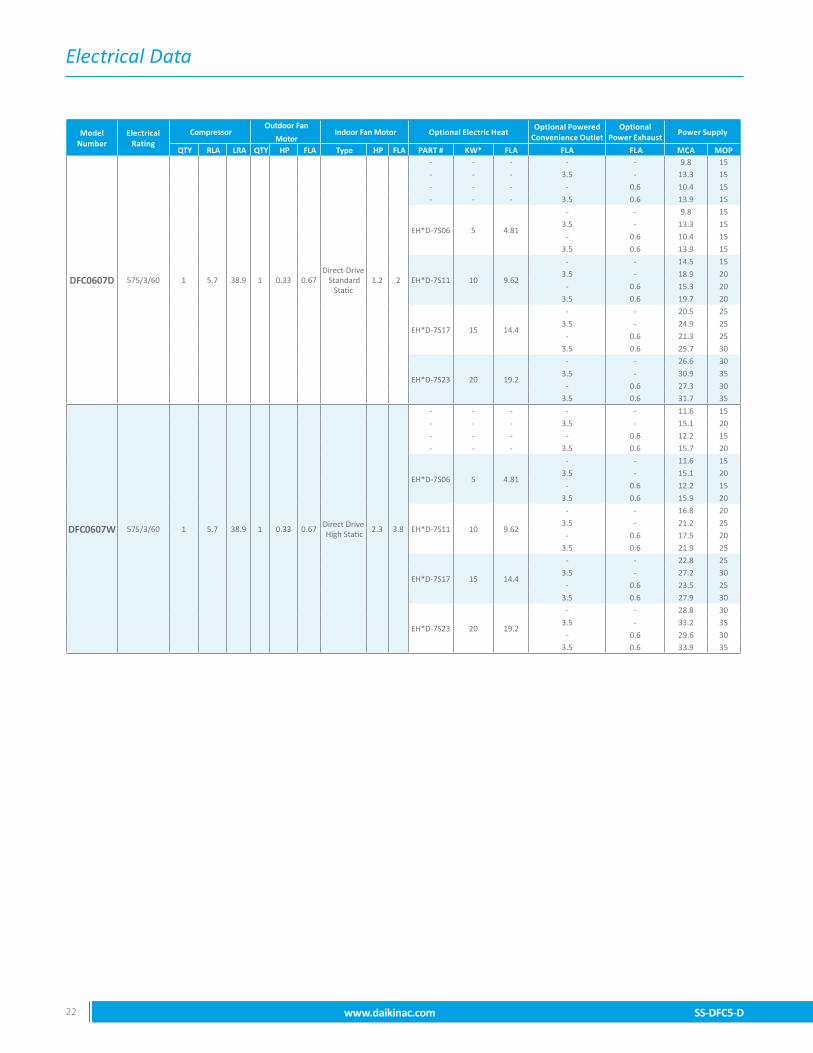
DFC0607D 575/3/60 1 5.7 38.9 1 0.33 0.67Direct-Drive
Standard Static
1.2 2
- - - - - 9.8 15- - - 3.5 - 13.3 15
- - - - 0.6 10.4 15
- - - 3.5 0.6 13.9 15
EH*D-7S06 5 4.81
- - 9.8 15
3.5 - 13.3 15
- 0.6 10.4 15
3.5 0.6 13.9 15
EH*D-7S11 10 9.62
- - 14.5 15
3.5 - 18.9 20
- 0.6 15.3 20
3.5 0.6 19.7 20
EH*D-7S17 15 14.4
- - 20.5 25
3.5 - 24.9 25
- 0.6 21.3 25
3.5 0.6 25.7 30
EH*D-7S23 20 19.2
- - 26.6 30
3.5 - 30.9 35
- 0.6 27.3 303.5 0.6 31.7 35
DFC0607W 575/3/60 1 5.7 38.9 1 0.33 0.67Direct Drive High Static
2.3 3.8
- - - - - 11.6 15- - - 3.5 - 15.1 20
- - - - 0.6 12.2 15
- - - 3.5 0.6 15.7 20
EH*D-7S06 5 4.81
- - 11.6 15
3.5 - 15.1 20
- 0.6 12.2 15
3.5 0.6 15.9 20
EH*D-7S11 10 9.62
- - 16.8 20
3.5 - 21.2 25
- 0.6 17.5 20
3.5 0.6 21.9 25
EH*D-7S17 15 14.4
- - 22.8 25
3.5 - 27.2 30
- 0.6 23.5 25
3.5 0.6 27.9 30
EH*D-7S23 20 19.2
- - 28.8 30
3.5 - 33.2 35
- 0.6 29.6 303.5 0.6 33.9 35

Wire Diagram
SS-DFC5-D www.daikinac.com 23
Wiri
ng i
s su
bjec
t to
cha
nge.
Alw
ays
refe
r to
the
wiri
ng d
iagr
am o
n th
e un
it fo
r th
e m
ost
up-t
o-da
te w
iring
.⚠
War
ning
High
Vol
tage
: D
isco
nnec
t al
l po
wer
bef
ore
serv
icin
g or
ins
talli
ng t
his
unit.
Mul
tiple
pow
er
sour
ces
may
be
pres
ent.
Failu
re to
do
so m
ay c
ause
pro
pert
y da
mag
e, p
erso
nal i
njur
y, o
r dea
th.⚡
1-Phase Diagram
1 2 3 4 5 6
1 2 3 4 5 6
LPS
BL
BK
BL
HPS
YL/P
K
BKYL
PLF
CC
PPL
M
YL/P
K
BL/P
K
BKYLBL
/PK
YLYLBR BK
FPS
BK BK
99
GR
BKR
D
CC
H
BKBK7
2CH
R 4
68
CH
R
BCBL
OW
ER C
ON
TAC
TOR
BMBL
OW
ER M
OTO
RC
APC
APAC
ITO
RC
BC
IRC
UIT
BR
EAKE
RC
CC
OM
PRES
SOR
CO
NTA
CTO
RC
CH
CR
ANKC
ASE
HEA
TER
CC
PC
OM
PRES
SOR
/CO
IL P
RO
TEC
TIO
NC
HR
CR
ANKC
ASE
HEA
TER
REL
AYC
HS
CR
ANKC
ASE
HEA
TER
SW
ITC
HC
MC
ON
DEN
SER
MO
TOR
CO
MP
CO
MPR
ESSO
REC
ON
ECO
NO
MIZ
EREH
KEL
ECTR
IC H
EATE
R K
ITES
EMER
GEN
CY
SHU
TDO
WN
FBFU
SE B
LOC
KFP
SFR
EEZE
PR
OTE
CTI
ON
SW
ITC
HG
ND
EQU
IPM
ENT
GR
OU
ND
HPS
HIG
H P
RES
SUR
E SW
ITC
HLP
SLO
W P
RES
SUR
E SW
ITC
HM
ATM
IXED
AIR
TEM
P. S
ENSO
RPB
POW
ER D
ISTR
IBU
TIO
N B
LOC
KPL
FFE
MAL
E PL
UG
/CO
NN
ECTO
RPL
MM
ALE
PLU
G/C
ON
NEC
TOR
RLY
REL
AYTB
TER
MIN
AL B
LOC
KTO
NO
N -
DEL
AY T
IMER
REL
AYTR
TRAN
SFO
RM
ER
TB1
STATW G R Y C O
WH
GR
PK YL BL OR
W1
W2 G R Y1 Y2 C O
TB1
STATW
1
G R Y1 C O
WH
GR
PK YL BL OR
W1
W2 G R Y1 Y2 C O
BRW
2
PUY2
5A
5B1 2 3 4
1 2 3 4
TON
t = 1
80s
R1 Y1
Y2R2
54321BM PLF1
1110987654321
121110987654321
ECO
NPL
F EX
TEC
ON
PLM
121110987654321
121110987654321
12
ECO
NPL
M
YL PU PU YL BL GR
GY
WH
PK WH
BR OR
PUYL
MAT PLF
21BK BK
10
CH
S
RD
BLR
DPK
7C
HR
10
PKBL
WH
RD
RD
GN
D
810
6
3
2 1 2 3 4 5A 5B 6 7 8 9 10
NOTE
S
REP
LAC
EMEN
T W
IRE
MU
ST B
E SA
ME
SIZE
AN
D T
YPE
OF
INSU
LATI
ON
AS
OR
IGIN
AL(A
T LE
AST
105°
C).
USE
CO
PPER
CO
ND
UC
TOR
S O
NLY
. USE
N.E
.C. C
LASS
2 W
IRE
FOR
ALL
LOW
VO
LTAG
E FI
ELD
CO
NN
ECTI
ON
S.
IF O
PTIO
NAL
EC
ON
OM
IZER
IS IN
STAL
LED
REM
OVE
EC
ON
PLM
JU
MPE
R A
ND
PLU
G IN
NEW
HAR
NES
S FR
OM
EC
ON
OM
IZER
KIT
TR1
PRIM
ARY
(HIG
H V
OLT
AGE)
CO
NN
ECTI
ON
S: O
RAN
GE
WIR
E C
ON
NEC
TED
TO
240
VTA
P AT
TH
E FA
CTO
RY
AND
BLA
CK
WIR
E TO
CO
M T
ERM
INAL
. FO
R 2
08V
SUPP
LYPO
WER
, MO
VE O
RAN
GE
WIR
E FR
OM
240
V TA
P TO
TH
E 20
8V T
AP.
FUSE
BLO
CKS
1-2
AR
E O
PTIO
NAL
IF O
PTIO
NAL
SAF
ETY
EQU
IPM
ENT
SUC
H A
S A
PHAS
E M
ON
ITO
R, F
LOAT
SW
ITC
H O
RSM
OKE
DET
ECTO
R IS
INST
ALLE
D, U
NPL
UG
JU
MPE
R P
LUG
AN
D P
LUG
IN S
AFET
YD
EVIC
E. IF
MU
LTIP
LE S
AFET
IES
ARE
INST
ALLE
D, P
LUG
IN T
HE
ADD
ITIO
NAL
DEV
ICES
IN S
ERIE
S. P
LUG
IN J
UM
PER
PLU
G A
T TH
E LA
ST S
AFET
Y D
EVIC
E IN
STAL
LED
.
IF A
TH
IRD
PAR
TY S
AFET
Y D
EVIC
E IS
FIE
LD IN
STAL
LED
, CU
T TH
E R
ED W
IRE
ON
TH
EJU
MPE
R P
LUG
AN
D W
IRE
A N
OR
MAL
LY C
LOSE
D D
RY
CO
NTA
CT
IN S
ERIE
S W
ITH
TH
EC
UT
WIR
E.
24 V
AC A
LAR
M O
UTP
UT
FRO
M O
PTIO
NAL
EC
ON
OM
IZER
CO
NTR
OL
MO
DU
LE.
CH
R, C
CH
, CH
S AN
D A
LL A
SSO
CIA
TED
WIR
ING
AR
E O
PTIO
NAL
.
TO C
HAN
GE
EVAP
OR
ATO
R M
OTO
R S
PEED
, MO
VE G
REE
N (F
AN O
NLY
), YE
LLO
W(C
OO
LIN
G),
OR
WH
ITE
(HIG
H H
EAT)
WIR
ES T
O A
PPR
OVE
D S
PEED
TAP
S, S
EE T
ABLE
.SE
E IN
STAL
LATI
ON
INST
RU
CTI
ON
S FO
R F
UR
THER
DET
AILS
ON
AD
JUST
ING
MO
TOR
.
REM
OVE
BLA
CK
JUM
PER
WIR
E IF
OPT
ION
AL F
REE
ZEST
AT IS
INST
ALLE
D.
IF O
PTIO
NAL
ELE
CTR
IC H
EAT
IS IN
STAL
LED
PLU
G IN
NEW
HAR
NES
S FR
OM
ELE
CTR
ICH
EATE
R K
IT. F
OR
TW
O S
TAG
E H
EAT,
REM
OVE
JU
MPE
R O
N T
B1.
L1T1
L2T2
BCFB
24
F2 F2
L1C
C
L2T2T1
4FB
1F1 F1
CC
A1A2
YLBL
BCA1
A2PK
BL
ALLO
WAB
LE S
PEED
TAP
S
T1T2
T3T4
T5FA
N (G
R)
X-
--
-C
OO
LIN
G (Y
L)-
XX
XX
HEA
TIN
G (B
R)
-X
XX
RLY
10
YLBL
W2
Y1O
Y2S2
RW
1C
S1G
DH
T1T2
T3T4
T5
WIR
E CO
DE
BLAC
KBL
UE
BLU
E W
ITH
PIN
K ST
RIP
EBR
OW
NG
REE
NG
RAY
OR
ANG
EPI
NK
PUR
PLE
RED
TAN
WH
ITE
YELL
OW
YELL
OW
WIT
H P
INK
STR
IPE
BK BL BL/P
KBR G
RG
YO
RPK PU R
DTN W
HYL YL
/PK
HIG
H V
OLT
AGE
LOW
VO
LTAG
EO
PTIO
NAL
HIG
H V
OLT
AGE
OPT
ION
AL L
OW
VO
LTAG
E
CH
ASSI
S G
RO
UN
D
F IEL
D W
IRIN
G
FACT
ORY
WIR
ING
HIG
H V
OLT
AGE
LOW
VO
LTAG
E
EAR
TH G
RO
UN
D
COM
PONE
NT L
EGEN
D
EHK
PLF
BA
CD
0140
L073
50-A
PLM
PLF
ES
TB1
PKR
DYL BR BL GR
WH
BL WH
BR
BRW
HYL
RD
RDPK BL
BRW
HYLYL
GY
BK
PBL1
L2
LIN
EVO
LTAG
E
BK RD
BK
TR1
CB
GR
208-
230V
/1PH
/60H
z
CO
MP
BKC R
S
PUYLGR
PK
WH
BR
PUYL
GR
WH
BR
CM
L1 L3
BR
CAP
OR
RD YL
BRBK PU
L2
CO
MPU
PUBK
BK
PLFC
MPL
M
987654321
TB2
BLBL
BK
PU
POW
ER A
ND C
ONT
ROLS
WIR
ING
DIA
GRA
MDF
C036
-060
, 1 P
HASE
, DIR
ECT
DRIV
E
BK
RD
BK
BL
BL
BLBL
RD
PK
2121
GR
GRM 1~ M 1~
GR GR GR
BLBK YL
WH
PU
PU
GR
PU
GR
YL
BL
THER
MO
STAT
++
THER
MO
STAT
FIE
LD W
IRIN
G++
1ST
AGE
CO
OLI
NG
/HEA
TIN
G2
STAG
E C
OO
LIN
G/H
EATI
NG
GY
PU
RD
BL
BL
PKBL
PK PK
BL
BL
PKBL
BL
PK
BKR
D
PK
WH
YLW
HG
R
HER
M
FAN
BM
GR
BK GR RD
BK RD
BK RD
PLM
2BM
PLF2
BM
M 1~
NGLC
NGLC
PUYLGR
WH
BR
PLM
1BM
4321 5
RD
BL PKBL
PK
RLY
78
BR
YLR
LY2
4YL
YL WH
WH
PK

Wire Diagram
24 www.daikinac.com SS-DFC5-D
BCBL
OW
ER C
ON
TAC
TOR
BMBL
OW
ER M
OTO
RC
APC
APAC
ITO
RC
BC
IRC
UIT
BR
EAKE
RC
CC
OM
PRES
SOR
CO
NTA
CTO
RC
CH
CR
ANKC
ASE
HEA
TER
CC
PC
OM
PRES
SOR
/CO
IL P
RO
TEC
TIO
NC
HR
CR
ANKC
ASE
HEA
TER
REL
AYC
HS
CR
ANKC
ASE
HEA
TER
SW
ITC
HC
MC
ON
DEN
SER
MO
TOR
CO
MP
CO
MPR
ESSO
REC
ON
ECO
NO
MIZ
EREH
KEL
ECTR
IC H
EATE
R K
ITES
EMER
GEN
CY
SHU
TDO
WN
FBFU
SE B
LOC
KFP
SFR
EEZE
PR
OTE
CTI
ON
SW
ITC
HG
ND
EQU
IPM
ENT
GR
OU
ND
HPS
HIG
H P
RES
SUR
E SW
ITC
HLP
SLO
W P
RES
SUR
E SW
ITC
HM
ATM
IXED
AIR
TEM
P. S
ENSO
RPB
POW
ER D
ISTR
IBU
TIO
N B
LOC
KPL
FFE
MAL
E PL
UG
/CO
NN
ECTO
RPL
MM
ALE
PLU
G/C
ON
NEC
TOR
RLY
REL
AYTB
TER
MIN
AL B
LOC
KTO
NO
N -
DEL
AY T
IMER
REL
AYTR
TRAN
SFO
RM
ER
PLF
PLM 4321
4321
ES
EHK
PLF 987654321
GR
24
68
BKR
D
CC
H
BK
CH
RBK
CH
R
7
WH
RD
5A
5B
WH
TB1
TSTA
T
W G R Y C O
WH
GR
PK YL BL OR
W1
W2 G R Y1 Y2 C O
TB1
TSTA
T
W1
G R Y1 C O
WH
GR
PK YL BL OR
W1
W2 G R Y1 Y2 C O
BRW
2
PUY2
BL RD
GY
GR
YL PU WH
BR BK
1110987654321
121110987654321
ECO
NPL
F EX
TEC
ON
PLM
121110987654321
121110987654321
12
ECO
NPL
MYL PU PU YL BL G
RG
YW
HPK W
HBR O
R
PUYL
MAT PLF
21BK BK
1 2 3 4 5 6
1 2 3 4 5 6
LPS
BL
BK
BL
HPS
YL/P
K
BKYL
PLF
CC
PPL
M
YL/P
K
BL/P
K
BKYLBL
/PK
BR
YL
BK
YL
9FP
SBK BK
9
CH
S
RD
BLR
DPK
7C
HR
10
PKBL
GN
D
108
3
1
8
2 39
4 5A 5B
7 1110
6
NOTE
S
REP
LAC
EMEN
T W
IRE
MU
ST B
E SA
ME
SIZE
AND
TYP
E O
F IN
SULA
TIO
N A
S O
RIG
INAL
(AT
LEAS
T 10
5° C
). U
SE C
OPP
ER C
ON
DU
CTO
RS
ON
LY. U
SE N
.E.C
. CLA
SS 2
WIR
E FO
R A
LLLO
W V
OLT
AGE
FIEL
D C
ON
NEC
TIO
NS.
IF O
PTIO
NAL
EC
ON
OM
IZER
IS IN
STAL
LED
REM
OVE
EC
ON
PLM
JU
MPE
R A
ND
PLU
G IN
NEW
HAR
NES
S FR
OM
EC
ON
OM
IZER
KIT
.
TR1
PRIM
ARY
(HIG
H VO
LTAG
E) C
ONN
ECTI
ONS
:O
RANG
E W
IRE
CONN
ECTE
D TO
240
/460
/575
VTA
P AT
THE
FAC
TOR
Y AN
D BL
ACK
WIR
E TO
CO
MTE
RMIN
AL. F
OR
208V
SUP
PLY
POW
ER, M
OVE
ORA
NGE
WIR
E FR
OM
240
V TA
P TO
THE
208
VTA
P.
FUSE
BLO
CKS
1-2
AR
E O
PTIO
NAL
.
IF O
PTIO
NAL
SAF
ETY
EQU
IPM
ENT
SUC
H A
S A
PHAS
E M
ON
ITO
R, F
LOAT
SW
ITC
H O
R S
MO
KED
ETEC
TOR
IS IN
STAL
LED
, UN
PLU
G J
UM
PER
PLU
G A
ND
PLU
G IN
SAF
ETY
DEV
ICE.
IFM
ULT
IPLE
SAF
ETIE
S AR
E IN
STAL
LED
, PLU
G IN
THE
ADD
ITIO
NAL
DEV
ICES
IN S
ERIE
S. P
LUG
IN J
UM
PER
PLU
G A
T TH
E LA
ST S
AFET
YD
EVIC
E IN
STAL
LED
.
IF A
TH
IRD
PAR
TY S
AFET
Y D
EVIC
E IS
FIE
LDIN
STAL
LED
, CU
T TH
E R
ED W
IRE
ON
TH
EJU
MPE
R P
LUG
AN
D W
IRE
A N
OR
MAL
LYC
LOSE
D D
RY
CO
NTA
CT
IN S
ERIE
S W
ITH
TH
EC
UT
WIR
E.
24 V
AC A
LAR
M O
UTP
UT
FRO
M O
PTIO
NAL
ECO
NO
MIZ
ER C
ON
TRO
L M
OD
ULE
.
CH
R, C
CH
, CH
S AN
D A
LL A
SSO
CIA
TED
WIR
ING
AR
E O
PTIO
NAL
.
TO C
HAN
GE
EVAP
OR
ATO
R M
OTO
RSP
EED
, MO
VE G
REE
N (F
AN O
NLY
),YE
LLO
W (C
OO
LIN
G),
OR
WH
ITE
(HIG
HH
EAT)
WIR
ES T
O A
PPR
OVE
D S
PEED
TAPS
, SEE
TAB
LE. S
EE IN
STAL
LATI
ON
INST
RU
CTI
ON
S FO
R F
UR
THER
DET
AILS
ON
AD
JUST
ING
MO
TOR
.
REM
OVE
BLA
CK
JUM
PER
WIR
E IF
OPT
ION
AL F
REE
ZEST
AT IS
INST
ALLE
D.
IF O
PTIO
NAL
ELE
CTR
IC H
EAT
ISIN
STAL
LED
PLU
G IN
NEW
HAR
NES
S FR
OM
ELEC
TRIC
HEA
TER
KIT
. FO
R T
WO
STA
GE
HEA
T, R
EMO
VE J
UM
PER
ON
TB1
.
ALTE
RN
ATE
1 P
HAS
E IN
DO
OR
BLO
WER
MO
TOR
.
106
2
L1C
C
L2T2T1
L3T3
L1BC
L2T2T1
L3T3
GR
RDBL
NGLC
NGLCBK
PLM
2BM
PLF2
BMM 1~
TB2
- C,D
BK RD
11
543212 3 541
PUYLGR
WH
BR
PLM
1BM
PUYLGR
WH
BR
PLF1
TB1
- T1
TB1
- T2
TB1
- T3
TB1
- T4
TB1
- T5 AL
TER
NAT
E 1
PHAS
E BL
OW
ER M
OTO
R
L1BC
T1
L2T2
L1 L2 TR1
OR
4FB
2F2 F2 F2
4FB
1 F1 F1 F1
CC
A1A2
YLBL
BCA1
A2PK
BL
RLY
10
YLBL
WIR
E CO
DE
BLAC
KBL
UE
BLU
E W
ITH
PIN
K ST
RIP
EBR
OW
NG
REE
NG
RAY
OR
ANG
EPI
NK
PUR
PLE
RED
TAN
WH
ITE
YELL
OW
YELL
OW
WIT
H P
INK
STR
IPE
BK BL BL/P
KBR G
RG
YO
RPK PU R
DTN W
HYL YL
/PK
HIG
H V
OLT
AGE
LOW
VO
LTAG
EO
PTIO
NAL
HIG
H V
OLT
AGE
OPT
ION
AL L
OW
VO
LTAG
E
CH
ASSI
S G
RO
UN
D
FIEL
D W
IRIN
G
FACT
ORY
WIR
ING H
IGH
VO
LTAG
ELO
W V
OLT
AGE
EAR
TH G
RO
UN
D
COM
PONE
NT L
EGEN
D
0140
L073
49-A
W2
Y1O
Y2S2
RW
1C
S1G
RD
DH
BR BA
CD
T1T2
T3T4
T5
PUPU
THER
MO
STAT
++
TB1
PKR
D
BL WH
BR
BRW
HYL
RD
RDPK BL
YL
TR1
CB
GR
TB2
BLBLBL
RD
PK
GR
GR
PUPU
BL
CO
MP
RDBK
L3L1
CAP
CM
PBL1
L2L3
LIN
EVO
LTAG
E
PUBR
BK PUBR
BK RD
OR
BK RD
OR
BK RD YL
L2
208-
230/
460/
575V
/3PH
/60H
z
BKPU
BK
PLF
PLM
CM
BK
BKR
DO
R
POW
ER A
ND C
ONT
ROLS
WIR
ING
DIA
GRA
MDF
C036
-060
, 3 P
HASE
, DIR
ECT
DRIV
E
2121
GR
GR M 1~M 3~
RDBK BK RD
OR
BKR
DO
R
OR
BK
BL
PU
PKYL
GR
PUBR
THER
MO
STAT
FIE
LD W
IRIN
G++
1ST
AGE
CO
OLI
NG
/HEA
TIN
G2
STAG
E C
OO
LIN
G/H
EATI
NG
GR
L1 L2 L3 GR
BM
PLF
2PL
M2
BK RD
OR
BM PLM
1
987654321
BK RD
OR
4321
4321
M 3~
GR
BM
TON
t = 1
80s
R1 Y1
BL
Y2R2
BK YL
BL
BM PLF1 987654321
PUYLGR
WH
BR
PUYL
GR
WH
BR
GYBL
GY
YL BL GR
WH
PKGY
BR
BK
GY
BL
PKPK
PK
PK
PKBL
BL
PKBL
PK
RD
BL
BL
WH
GR
YLW
H
GR
YLW
HG
R
RLY
78
YLR
LY2
4YL
YL WH
WH
ALLO
WAB
LE S
PEED
TAP
S
T1T2
T3T4
T5FA
N (G
R)
X-
--
-C
OO
LIN
G (Y
L)-
XX
XX
HEA
TIN
G (B
R)
-X
XX
3-Phase Diagram
Wiri
ng i
s su
bjec
t to
cha
nge.
Alw
ays
refe
r to
the
wiri
ng d
iagr
am o
n th
e un
it fo
r th
e m
ost
up-t
o-da
te w
iring
.⚠
War
ning
Hig
h Vo
ltage
: D
isco
nnec
t al
l po
wer
bef
ore
serv
icin
g or
ins
talli
ng t
his
unit.
Mul
tiple
pow
er
sour
ces
may
be
pres
ent.
Failu
re to
do
so m
ay c
ause
pro
pert
y da
mag
e, p
erso
nal i
njur
y, o
r dea
th.⚡

Wire Diagram
SS-DFC5-D www.daikinac.com 25
Wiri
ng i
s su
bjec
t to
cha
nge.
Alw
ays
refe
r to
the
wiri
ng d
iagr
am o
n th
e un
it fo
r th
e m
ost
up-t
o-da
te w
iring
.⚠
War
ning
High
Vol
tage
: D
isco
nnec
t al
l po
wer
bef
ore
serv
icin
g or
ins
talli
ng t
his
unit.
Mul
tiple
pow
er
sour
ces
may
be
pres
ent.
Failu
re to
do
so m
ay c
ause
pro
pert
y da
mag
e, p
erso
nal i
njur
y, o
r dea
th.⚡
3-Phase Diagram
BCBL
OW
ER C
ON
TAC
TOR
BMBL
OW
ER M
OTO
RC
APC
APAC
ITO
RC
BC
IRC
UIT
BR
EAKE
RC
CC
OM
PRES
SOR
CO
NTA
CTO
RC
CH
CR
ANKC
ASE
HEA
TER
CC
PC
OM
PRES
SOR
/CO
IL P
RO
TEC
TIO
NC
HR
CR
ANKC
ASE
HEA
TER
REL
AYC
HS
CR
ANKC
ASE
HEA
TER
SW
ITC
HC
MC
ON
DEN
SER
MO
TOR
CO
MP
CO
MPR
ESSO
REC
ON
ECO
NO
MIZ
EREH
KEL
ECTR
IC H
EATE
R K
ITES
EMER
GEN
CY
SHU
TDO
WN
FBFU
SE B
LOC
KFP
SFR
EEZE
PR
OTE
CTI
ON
SW
ITC
HG
ND
EQU
IPM
ENT
GR
OU
ND
HPS
HIG
H P
RES
SUR
E SW
ITC
HLP
SLO
W P
RES
SUR
E SW
ITC
HM
ATM
IXED
AIR
TEM
P. S
ENSO
RPB
POW
ER D
ISTR
IBU
TIO
N B
LOC
KPL
FFE
MAL
E PL
UG
/CO
NN
ECTO
RPL
MM
ALE
PLU
G/C
ON
NEC
TOR
RLY
REL
AYTB
TER
MIN
AL B
LOC
KTO
NO
N -
DEL
AY T
IMER
REL
AYTR
TRAN
SFO
RM
ER
PLF
PLM 4321
4321
ES
EHK
PLF 987654321
GR
24
68
BKR
D
CC
H
BK
CH
RBK
CH
R
7
WH
RD
5A
5B
WH
TB1
TSTA
T
W G R Y C O
WH
GR
PK YL BL OR
W1
W2 G R Y1 Y2 C O
TB1
TSTA
T
W1
G R Y1 C O
WH
GR
PK YL BL OR
W1
W2 G R Y1 Y2 C O
BRW
2
PUY2
BL RD
GY
GR
YL PU WH
BR BK
1110987654321
121110987654321
ECO
NPL
F EX
TEC
ON
PLM
121110987654321
121110987654321
12
ECO
NPL
MYL PU PU YL BL G
RG
YW
HPK W
HBR O
R
PUYL
MAT PLF
21BK BK
1 2 3 4 5 6
1 2 3 4 5 6
LPS
BL
BK
BL
HPS
YL/P
K
BKYL
PLF
CC
PPL
M
YL/P
K
BL/P
K
BKYLBL
/PK
BR
YL
BK
YL
9FP
SBK BK
9
CH
S
RD
BLR
DPK
7C
HR
10
PKBL
GN
D
1011
3
1
8
2 39
4 5A 5B
7 1110
6
NOTE
S
REP
LAC
EMEN
T W
IRE
MU
ST B
E SA
ME
SIZE
AND
TYP
E O
F IN
SULA
TIO
N A
S O
RIG
INAL
(AT
LEAS
T 10
5° C
). U
SE C
OPP
ER C
ON
DU
CTO
RS
ON
LY. U
SE N
.E.C
. CLA
SS 2
WIR
E FO
R A
LLLO
W V
OLT
AGE
FIEL
D C
ON
NEC
TIO
NS.
IF O
PTIO
NAL
EC
ON
OM
IZER
IS IN
STAL
LED
REM
OVE
EC
ON
PLM
JU
MPE
R A
ND
PLU
G IN
NEW
HAR
NES
S FR
OM
EC
ON
OM
IZER
KIT
.
TR1
PRIM
ARY
(HIG
H VO
LTAG
E) C
ONN
ECTI
ONS
:O
RANG
E W
IRE
CONN
ECTE
D TO
240
/460
/575
VTA
P AT
THE
FAC
TOR
Y AN
D BL
ACK
WIR
E TO
CO
MTE
RMIN
AL. F
OR
208V
SUP
PLY
POW
ER, M
OVE
ORA
NGE
WIR
E FR
OM
240
V TA
P TO
THE
208
VTA
P.
FUSE
BLO
CKS
1-2
AR
E O
PTIO
NAL
.
IF O
PTIO
NAL
SAF
ETY
EQU
IPM
ENT
SUC
H A
S A
PHAS
E M
ON
ITO
R, F
LOAT
SW
ITC
H O
R S
MO
KED
ETEC
TOR
IS IN
STAL
LED
, UN
PLU
G J
UM
PER
PLU
G A
ND
PLU
G IN
SAF
ETY
DEV
ICE.
IFM
ULT
IPLE
SAF
ETIE
S AR
E IN
STAL
LED
, PLU
G IN
THE
ADD
ITIO
NAL
DEV
ICES
IN S
ERIE
S. P
LUG
IN J
UM
PER
PLU
G A
T TH
E LA
ST S
AFET
YD
EVIC
E IN
STAL
LED
.
IF A
TH
IRD
PAR
TY S
AFET
Y D
EVIC
E IS
FIE
LDIN
STAL
LED
, CU
T TH
E R
ED W
IRE
ON
TH
EJU
MPE
R P
LUG
AN
D W
IRE
A N
OR
MAL
LYC
LOSE
D D
RY
CO
NTA
CT
IN S
ERIE
S W
ITH
TH
EC
UT
WIR
E.
24 V
AC A
LAR
M O
UTP
UT
FRO
M O
PTIO
NAL
ECO
NO
MIZ
ER C
ON
TRO
L M
OD
ULE
.
CH
R, C
CH
, CH
S AN
D A
LL A
SSO
CIA
TED
WIR
ING
AR
E O
PTIO
NAL
.
TO C
HAN
GE
EVAP
OR
ATO
R M
OTO
RSP
EED
, MO
VE G
REE
N (F
AN O
NLY
),YE
LLO
W (C
OO
LIN
G),
OR
WH
ITE
(HIG
HH
EAT)
WIR
ES T
O A
PPR
OVE
D S
PEED
TAPS
, SEE
TAB
LE. S
EE IN
STAL
LATI
ON
INST
RU
CTI
ON
S FO
R F
UR
THER
DET
AILS
ON
AD
JUST
ING
MO
TOR
.
REM
OVE
BLA
CK
JUM
PER
WIR
E IF
OPT
ION
AL F
REE
ZEST
AT IS
INST
ALLE
D.
IF O
PTIO
NAL
ELE
CTR
IC H
EAT
ISIN
STAL
LED
PLU
G IN
NEW
HAR
NES
S FR
OM
ELEC
TRIC
HEA
TER
KIT
. FO
R T
WO
STA
GE
HEA
T, R
EMO
VE J
UM
PER
ON
TB1
.
MO
VE G
RAY
(GY)
WIR
E TO
TB1
- S2
TO
ENAB
LE T
6-T1
0 SP
EED
TAP
, SEE
TAB
LE.
106
2
L1C
C
L2T2T1
L3T3
L1BC
L2T2T1
L3T3
4FB
2F2 F2 F2
4FB
1 F1 F1 F1
CC
A1A2
YLBL
BCA1
A2PK
BL
RLY
10
YLBL
8
WIR
E CO
DE
BLAC
KBL
UE
BLU
E W
ITH
PIN
K ST
RIP
EBR
OW
NG
REE
NG
RAY
OR
ANG
EPI
NK
PUR
PLE
RED
TAN
WH
ITE
YELL
OW
YELL
OW
WIT
H P
INK
STR
IPE
BK BL BL/P
KBR G
RG
YO
RPK PU R
DTN W
HYL YL
/PK
HIG
H V
OLT
AGE
LOW
VO
LTAG
EO
PTIO
NAL
HIG
H V
OLT
AGE
OPT
ION
AL L
OW
VO
LTAG
E
CH
ASSI
S G
RO
UN
D
FIEL
D W
IRIN
G
FACT
ORY
WIR
ING H
IGH
VO
LTAG
ELO
W V
OLT
AGE
EAR
TH G
RO
UN
D
COM
PONE
NT L
EGEN
D
0140
L073
54-A
W2
Y1O
Y2S2
RW
1C
S1G
RD
DH
BR BA
CD
T1T2
T3T4
T5
PUPU
THER
MO
STAT
++
TB1
PKR
D
BL WH
BR
BRW
HYL
RD
RDPK BL
YL
TR1
CB
GR
TB2
BLBLBL
RD
PK
GR
GR
PUPU
BL
CO
MP
RDBK
L3L1
CAP
CM
PBL1
L2L3
LIN
EVO
LTAG
E
PUBR
BK PUBR
BK RD
OR
BK RD
OR
BK RD YL
L2
208-
230/
460/
575V
/3PH
/60H
z
BKPU
BK
PLF
PLM
CM
BK
BKR
DO
R
POW
ER A
ND C
ONT
ROLS
WIR
ING
DIA
GRA
MDF
C036
-060
, 3 P
HASE
, HIG
H ST
ATIC
DIRE
CT D
RIVE
2121
GR
GR M 1~M 3~
RDBK BK RD
OR
BKR
DO
R
OR
BK
BL
PU
PKYL
GR
PUBR
THER
MO
STAT
FIE
LD W
IRIN
G++
1ST
AGE
CO
OLI
NG
/HEA
TIN
G2
STAG
E C
OO
LIN
G/H
EATI
NG
GR
L1 L2 L3 GR
BM
PLF
2PL
M2
BK RD
OR
BM PLM
1
987654321
BK RD
OR
4321
4321
M 3~
GR
BM
TON
t = 1
80s
R1 Y1
BL
Y2R2
BK YL
BL
BM PLF1 987654321
PUYLGR
WH
BR
PUYL
GR
WH
BR
GYBL
GY
YL BL GR
WH
PKGY
BR
BK
GY
BL
PKPK
PK
PK
PKBL
BL
PKBL
PK
RD
BL
BL
WH
GR
YLW
H
GR
YLW
HG
R
RLY
78
YLR
LY2
4YL
YL WH
WH
GY
GY
ALLO
WAB
LE S
PEED
TAP
S
T1T2
T3T4
T5T6
T7T8
T9T1
0FA
N/L
OW
HEA
X-
--
-X
--
--
CO
OLI
NG
(YL)
-X
XX
X-
XX
XX
HIG
H H
EAT
--/X
XX
X-
-/XX
XX
TB1-
DH
= 0
VAC
, USE
SPE
ED T
AP T
1 - T
5.TB
1 - D
H =
24
VAC
, USE
SPE
ED T
AP T
6 - T
10.

DBC3-D
Dimensional Data
26 www.daikinac.com SS-DFC5-D
Dimensions — 3 - 5 Tons
Model Size DIM “A”
5 ton AC 39⅞

SS-DFC5-D www.daikinac.com 27
DBC3-D
Electrical Connections
Unit ClearancesService ClearanceAllow for recommended service clearances as shown in figure to the right. In situations that have multiple units, a 36” minimum clearance is required between the condenser coils. A clearance of 48” is recommended on all sides of the unit to allow service access and to ensure proper ventilation and condenser airflow. The top of the unit should be unobstructed. Provide a roof walkway along the sides of the unit for service and access to controls and components. Contact your Daikin sales representative for service requirements less than those recommended.
24" MIN. 24" MIN.
36” MIN.
LOW VOLTAGE BLOCK
CONTROL BOX
THERMOSTAT WIRE
GROUND LUG
POWER SUPPLYLINE VOLTAGE

28 www.daikinac.com SS-DFC5-D
DBC3-D
Unit LocationThe structural engineer must verify that the roof has adequate support and ability to minimize deflection. Take extreme caution when using on a wooden roof structure. Unit condenser coils should be in a location that avoids any heated exhaust air.
Allow sufficient space around the unit for maintenance/service clearance. Consult your Daikin sales representative if available clearances do not meet minimum recommendations.
Where code considerations, such as the NEC, require extended clearances, these take precedence.
Provisions for forks have been included in the unit base frame. No other fork locations are approved.
» Unit must be lifted by the four lifting holes located at the base frame corners.
» Lifting cables should be attached to the unit with shackles.
» The distance between the crane hook and the top of the unit must not be less than 60”.
» Two spreader bars must span over the unit to prevent damage to the cabinet by the lift cables. Spreader bars must be of sufficient length so that cables do not come in contact with the unit during transport. Remove wood struts mounted beneath unit base
Installation
frame before setting unit on roof curb. These struts are intended to protect unit base frame from forklift damage. To remove the struts, extract the sheet metal retainers and pull the struts through the base of the unit. Refer to rigging label on the unit.
Important: If using bottom discharge with roof curb, duct-work should be attached to the curb prior to installing the unit. Refer to the Roof Curb Installation Instructions for proper curb installation. Curbing must be installed in compliance with the National Roofing Contractors Association Manual. Lower unit carefully onto roof mounting curb. While rigging the unit, the center of gravity will cause the condenser end to be lower than the supply air end. Bring condenser end of unit into alignment with the curb. With condenser end of the unit resting on curb member and using curb as a fulcrum, lower opposite end of the unit until entire unit is seated on the curb. When a rectangular cantilever curb is used, take care to center the unit. Check for proper alignment and orientation of supply and return openings with duct.
Roof Curb InstallationThe roof curb is field-assembled and must be installed level (within 1/16” per foot side to side). A sub-base must be constructed by the contractor in applications involving pitched roofs. Gaskets are furnished and must be installed between the unit and curb. For proper installation, follow NRCA guidelines. In applications requiring post and rail installation, an I-beam securely mounted on multiple posts should support the unit on each side. In addition, the insulation on the underside of the unit should be protected from the elements. Applications in geographic areas subjected to seismic or hurricane conditions must meet code requirements for fastening the unit to the curb and the curb to the building structure. For further and more detailed information please refer to our Daikin Light Commercial Packaged unit IOD.
Corner & Center-of-Gravity Locations
Weights
ModelShipping
Weight (lbs)Operating
Weight (lbs)Corner Weights (lbs) Length Width
A B C D X (in) Y (in)
DFC0601D000001S 582 512 113 166 104 129 33⁴⁄₅ 27⁴⁄₅
DFC0603D000001S 578 508 113 162 104 129 33�⁄10 27�⁄10
DFC0604D000001S 582 512 113 162 104 133 34⅓ 27⁴⁄₅
DFC0607D000001S 582 512 113 162 104 133 34⅓ 27⁴⁄₅

Accessories
SS-DFC5-D www.daikinac.com 29
DBC3-D
Accessories availability may vary.
Field Accessory part number
DescriptionFits Model
SizesField-
InstalledFactory-Installed
Operating Weight (lbs)
Electric Heat KitsEHXD-1S06 Electric Heater, Direct Drive, 208-230V, 1PH, 5kW 5 ton √
EHXD-1S11 Electric Heater, Direct Drive, 208-230V, 1PH, 10kW 5 ton √
EHXD-1S17 Electric Heater, Direct Drive, 208-230V, 1PH, 15kW 5 ton √
EHXD-1S23 Electric Heater, Direct Drive, 208-230V, 1PH, 20kW 5 ton √
EHXD-3S06 Electric Heater, Direct Drive, 208-230V, 3PH, 5kW 5 ton √
EHXD-3S11 Electric Heater, Direct Drive, 208-230V, 3PH, 10kW 5 ton √
EHXD-3S17 Electric Heater, Direct Drive, 208-230V, 3PH, 15kW 5 ton √
EHXD-3S23 Electric Heater, Direct Drive, 208-230V, 3PH, 20kW 5 ton √
EHXD-4S06 Electric Heater, Direct Drive, 460V, 3PH, 5kW 5 ton √
EHXD-4S11 Electric Heater, Direct Drive, 460V, 3PH, 10kW 5 ton √
EHXD-4S17 Electric Heater, Direct Drive, 460V, 3PH, 15kW 5 ton √
EHXD-4S23 Electric Heater, Direct Drive, 460V, 3PH, 20kW 5 ton √
EHXD-7S06 Electric Heater, Direct Drive, 575V, 3PH, 5kW 5 ton √
EHXD-7S11 Electric Heater, Direct Drive, 575V, 3PH, 10kW 5 ton √
EHXD-7S17 Electric Heater, Direct Drive, 575V, 3PH, 15kW 5 ton √
EHXD-7S23 Electric Heater, Direct Drive, 575V, 3PH, 20kW 5 ton √
Duct Smoke DetectorsDuct Smoke Detectors - Return 5 ton √ 11
Duct Smoke Detectors - Supply 5 ton √ 11
Duct Smoke Detectors - Supply and Return 5 ton √ 11
Non-Fused Disconnect Switch60 Amp Disconnect 5 ton √ 5
100 Amp Disconnect 5 ton √ 5
150 Amp Disconnect 5 ton √ 5
Convenience OutletsConvenience Outlets - Powered, 208/230 V 5 ton √ 42
Convenience Outlets - Non-Powered 5 ton √ 2
Hinged Access PanelsHinged Access Panels, 39” cabinet 5 ton √
Economizer0270L01163 Horizontal Economizer Ultra Low-Leak (Title 24) JADE™ Dry-Bulb, 39” cabinet 5 ton √ 88
0270L01759 Horizontal Economizer Ultra Low-Leak (Title 24) JADE Enthalpy Sensor, 39” cabinet 5 ton √ 88
0270L01753 Downflow Economizer Standard Low-Leak JADE Ethalpy Sensor 5 ton √ √ 65
0270L01755 Downflow Economizer Ultra Low-Leak (Title 24) JADE Ethalpy Sensor 5 ton √ √ 65
0270L01156 Downflow Economizer Standard Low-Leak JADE Dry-Bulb 5 ton √ √ 65
0270L01158 Downflow Economizer Ultra Low-Leak (Title 24) JADE Dry-Bulb 5 ton √ √ 65
Curbs and Restraint Clips 0221L00014 Roof Curb 14” Tall, Knocked Down 5 ton √ 80
0221L00015 Roof Curb 24” Tall, Knocked Down 5 ton √ 109
0270L01261 Hold Down Bracket Kit 5 ton √ 8
0270L01250 Hold Down Bracket Kit for Daikin Roofcurb 5 ton √ 8
0221L00019 Roof Curb 14” Tall Seismic with Hold Down Brackets, Knocked Down 5 ton √ 102
0221L00020 Roof Curb 14” Tall Wind-Rated Hurricane with Hold Down Brackets, Welded 5 ton √ 140
Concentrics0270L01602 Concentric Diffuser 24 x 48 with 16” dia collars 5 ton √ 32
0270L01603 Concentric Diffuser 24 x 48 with 18” dia collars 5 ton √ 35
0270L01335 Concentric Duct Adaptor Kit for 16” Dia. Duct 5 ton √ 28
0270L01338 Concentric Duct Adaptor Kit for 18” Dia. Duct 5 ton √ 28

Accessories
30 www.daikinac.com SS-DFC5-D
Field Accessory part number
DescriptionFits Model
SizesField-
InstalledFactory-Installed
Operating Weight (lbs)
Dampers0270L01165 2 Position Motorized Damper 5 ton √ 40
0270L01166 Manual Outdoor Air Damper 5 ton √ 24
Hail Guard KitsHAILGD036HE Condenser Coil Hail Guards, 39” cabinet 5 ton √ √
Crankcase Heater KitsHECH4860230 Crankcase heater Kit 208/230 V 5 ton √ √ 1
High-Efficiency Filters0160L00271 High Efficiency MERV 8 Air Filter Kit - 20x25x2 (qty 2) 5 ton √ 4
0160L00202 High Efficiency MERV 13 Air Filter Kit - 20x25x2 (qty 2) 5 ton √ 4
Misc AccessoriesTTBCKHE01 Through the Base Gas/Electrical 5 ton √ √ 1
3PMKP1 Phase Monitor Kit 5 ton √ √ 2
0270L01232 Burglar bars Inserts 5 ton √ 18
Power Exhaust0270L01167 Power Exhaust Prop Downflow Economizer, 1 phase, 230 V √ 57
0270L01170 Power Exhaust Prop Horizontal Economizer, 1 phase, 230 V √ 47
E-Coated Coils
E-coated Coil 5 ton √included in
operating weight
Controls, Thermostats and SensorsDT4272C Comm Touch Digital Stat w/ WiFi 4h/2c 3-25 ton √ 1
DT4273C Comm Touch Digital Stat w/ WiFi & Humidity Control 4h/2cc 3-25 ton √ 1
PSPAC-WS Remote indoor sensor 3-25 ton √ 1
250803400 AppStat™ RTU 2H/2C Econ 3-25 ton √ 1
250803600 AppStat™ HPU 3H/2C Econ (Heat Pump) 3-25 ton √ 1
D4271C 4h/2c Commercial 7day Programmable Wi-Fi Capable thermostat 3-25 ton √ 1
D4272C 4h/2c Commercial 7day Programmable Wi-Fi Capable Hum/dehum thermostat 3-25 ton √ 1
C7232A1024 CO2 Sensor (Wall Mtd) 3-25 ton √ 1
C7232B1022 CO2 Sensor (Duct Mtd) 3-25 ton √ 1
D2270C Mini Wi-Fi Thermostat 3-25 ton √ 1
TSTATD2152-2 Value Series 2h/1c 5+2 prgm (Heat Pump) 3-25 ton √ 1
TSTATD2100-2 Value Series 2h/1c No prgm (Heat Pump) 3-25 ton √ 1
TSTATD1100-2 Value Series 1h/1c No prgm 3-25 ton √ 1
TSTATD1152-2 Value Series 1h/1c 5+2 prgm 3-25 ton √ 1
PSPAC-AW Add-A-Wire 3-25 ton √ 1
PSPAC-2W 2-Wire Kit 3-25 ton √ 1
PSPAC-OS Wired Indoor / Outdoor Remote Sensor 3-25 ton √ 1
PSPAC-DS Wired Duct Sensor 3-25 ton √ 1
PSPAC-WFMS Wireless Wi-Fi Mini Sensor 3-25 ton √ 1
PSPAC-LR Lock Ring for Premium Commercial Thermostats 3-25 ton √ 1
PSPAC-PWF Wi-Fi Module 3-25 ton √ 1
PSPAC-WP Wall Plate - Premium & Value Series 3-25 ton √ 1
PSPAC-WPT Wall Plate Color Touch Screen 3-25 ton √ 1
PSPAC-WPM-S Wall Plate Premium Mini - Small 3-25 ton √ 1
PSPAC-WPM-M Wall Plate Premium Mini - Medium 3-25 ton √ 1
PSPAC-WPM-L Wall Plate Premium Mini - Large 3-25 ton √ 1
C7400S1000 Differential Enthalpy Sensor 3-25 ton √ 1
D4120 Smoke Detector- Duct Mounted 3-25 ton √ 1
D4120W Smoke Detector- Watertight 3-25 ton √ 1Accessories availability may vary.

Factory and Field Installed Options
SS-DFC5-D www.daikinac.com 31
Factory Installed Options » Non-Powered Convenience Outlet: A 120V, 15A, GFCI outlet can be installed in the unit making it easier for technicians to service other units once an electrician runs power to the outlet. Outlet shall be factory-installed and internally mounted with easily accessible 120-v female receptacle. Transformer not included for this option. Outlet shall include a field-installed “While-in-Use” cover.
» Powered Convenience Outlet:A 115V, 15A, GFCI outlet can be powered with a step-transformer built into the unit. When a factory-installed powered convenience outlet is installed in the equipment, the unit MCA (Min. Circuit Ampacity) will increase by 9.6A for 208V units; increase by 8.7A for 230V; increase by 4.35A for 460V units; and by 3.5A for 575V units. The MOP (Max. Overcurrent Protection) device must be sized accordingly. Outlet shall be powered from main line power to the rooftop unit. Outlet shall include a field installed “While-in-Use” cover.
» Return Air and/or Supply Air Smoke Detectors: Return air and/or supply air smoke detectors can be installed in the unit. To safely identify the presence of smoke inside the air conditioning system and shutdown the blower to prevent the smoke to disperse into different zones.
» Disconnect Switch (non-fused): A disconnect switch can be installed in the unit with factory wiring complete from the switch to the unit. Please note that for air conditioner and heat pump units, the appropriate electric heat kit must be ordered along with the disconnect switch (non-fused) to be factory-installed. For models with a powered convenience outlet option and a disconnect switch (non-fused) option, the power to the powered convenience outlet will be shut off when the disconnect switch (non-fused) is in the off position. National Electric Code (NEC) and UL approved non-fused switch shall provide unit power shutoff. The switch shall be accessible from outside of the unit and provide local shutdown and lockout capability.
» Hinged Access Panels: Allows access to unit’s major components. Combined with latches for easy access to control box, compressor, filters and blower motor.
» Through-the-base electrical connection: Allows an easy and fast field installation through the unit base pan.
» Electromechanical Controls: Basic controls that include terminal block for unit connectivity to T-Stat.
Field Installed Options » Manual Fresh Air Damper: Manual damper package shall consist of damper, air inlet screen, and rain hood which can be preset to admit up to 25% outdoor air for year round ventilation.
» Motorized Fresh Air Damper: A two-position damper with rain hood and screen provides up to 50% outside air when the indoor fan starts and closes when the indoor fan shuts down. Consist of actuator, damper, air inlet screen, and rain hood. Damper shall close upon indoor (evaporator) fan shutoff and/or loss of power. The damper actuator shall plug into the rooftop unit’s wiring harness plug. No hard wiring shall be required.
» Power Exhaust: Power exhaust shall be used in conjunction with an integrated economizer. This accessory exhausts return air and may be used in either downflow or horizontal (duct-mounted) applications. Horizontal power exhaust shall be mounted in return ductwork. Power exhaust shall be controlled by economizer controller operation. Exhaust fans shall be energized when dampers open past the 0-100% adjustable setpoint on the economizer control.
» Horizontal Economizer: Fully modulating between 0 and 100%, contain seals that meet ASHRAE 90.1 requirements. Includes motor and dampers, minimum position settings, preset linkage, wiring harness with plug, mixed air temperature sensor, and enthalpy control. An optional duct-mounted barometric relief damper is available. An optional return enthalpy sensor is available to provide comparative or differential enthalpy control. Damper blades shall be galvanized steel with composite gears. Plastic or composite blades on intake or return shall not be acceptable. Standard leak rate shall be equipped with dampers not to exceed 2% leakage at 1 in. wg pressure differential. Ultra Low Leak design meets California Title 24 section 140.4 and ASHRAE 90.1 requirements for 4 cfm per sq.ft. on the outside air dampers and 10 cfm per sq. ft. on the return dampers. Shall be designed to close damper(s) during loss-of-power situations with spring return built into motor. Economizer controller shall accept a 2-10 Vdc CO2 sensor input for IAQ/DCV control. In this mode, dampers shall modulate the outdoor air damper to provide ventilation based on the sensor input.
» Economizer controller shall be Honeywell® JADE® W7220 that provides:
- 2-line LCD interface screen for setup, configuration and troubleshooting.
- On-board Fault Detection and Diagnostics (FDD) that senses and alerts when the economizer is not operating properly, per California Title 24.
- Sensor failure loss of communication identification
- Automatic sensor detection
- Capabilities for use with multiple-speed indoor fan systems
- Utilize digital sensors: Dry bulb and Enthalpy
- Economizer controller shall provide indications when in free cooling mode, in the DCV mode, or the exhaust fan contact is closed.

32 www.daikinac.com SS-DFC5-D
Our continuing commitment to quality products may mean a change in specifications without notice. ©2021 • Houston, Texas • Printed in the USA.
» Roof curbs: Full perimeter roof curb with exhaust capability providing separate air streams for energy recovery from the exhaust air without supply air contamination. Two different heights 14” and 24”, allows proper installation and structure stability. Formed galvanized steel with wood nailer strip and shall be capable of supporting entire unit weight.
» Concentric duct kits: Designed to provide a single-point air distribution system with the added benefit of having directional air control.
» Restraint mounting clips: Allows for installation reinforcement for Hurricane and/or seismic events.
» CO2 sensor: Sensor designed to alarm the system when the CO2 levels are outside safe parameters.
» Burglar Bar Sleeves: Designed to prevent the access thru the return or supply ducting inside the unit.
» Downflow square to round adapter 18": Installed into a recessed portion of the roof curb, the concentric duct adaptor changes the orientation of the ductwork from square to round for applications utilizing that type of ducting system.
» Side discharge concentric diffuser system: The Concentric diffuser system is an all in one supply and return duct free arrangement for RTU systems. This system comes with two separate duct connections, one for a supply and another for a return.
» Remote indoor sensor: Remote sensor to monitor the temperature on zones away from the main thermostat.
» Drain pan overflow switch: Allows the controls to detect and send an alarm when there is an overflow on the drain pan.
» Freeze stat: Temperature sensing device that monitors the heat exchange to prevent the coil from freezing.
Factory and Field Installed Options » Downflow Economizer: Fully modulating between 0 and
100%, contain seals that meet ASHRAE 90.1 requirements. Includes motor and dampers, minimum position settings, a preset linkage, a wiring harness with plug, a mixed air temperature sensor, enthalpy control, and a barometric relief damper. An optional return enthalpy sensor is available to provide comparative or differential enthalpy control. Damper blades shall be galvanized steel with composite gears. Plastic or composite blades on intake or return shall not be acceptable. Standard leak rate shall be equipped with dampers not to exceed 2% leakage at 1 in. wg pressure differential. Ultra Low Leak design meets California Title 24 section 140.4 and ASHRAE 90.1 requirements for 4 cfm per sq.ft. on the outside air dampers and 10 cfm per sq. ft. on the return dampers. Shall be designed to close damper(s) during loss-of-power situations with spring return built into motor. Economizer controller shall accept a 2-10 Vdc CO2 sensor input for IAQ/DCV control. In this mode, dampers shall modulate the outdoor air damper to provide ventilation based on the sensor input. Economizer controller shall be Honeywell® W7220 that provides:
» Economizer controller shall be Honeywell W7220 that provides:
- 2-line LCD interface screen for setup, configuration and troubleshooting.
- On-board Fault Detection and Diagnostics (FDD) that senses and alerts when the economizer is not operating properly, per California Title 24.
- Sensor failure loss of communication identification
- Automatic sensor detection
- Capabilities for use with multiple-speed indoor fan systems
- Utilize digital sensors: Dry bulb and Enthalpy
- Economizer controller shall provide indications when in free cooling mode, in the DCV mode, or the exhaust fan contact is closed.
» Low Ambient Control: Allows cooling operation down to 35°F outdoor ambient temperature for 3 - 6 ton units.
» Phase Monitor: Phase monitor (3-Phase only) shall provide protection for motors and compressors against problems caused by phase loss, phase reversal and phase unbalance. Phase monitor is equipped with an LED that provides an ON or FAULT indicator.
» Condenser Hail Guards: Louvered metal guards help protect the condenser coil from hail and debris; available as a field-installed options on 3 – 12½ ton units.
Factory and Field Installed Options