2018 ARCHITECTURAL/ENGINEERING GUIDELINES
85
TEXAS FACILITIES COMMISSION Edit Date: 3/19/2018 2018 ARCHITECTURAL/ENGINEERING GUIDELINES This document has been revised and replaces the previously published document dated 8/24/2017. Changes highlighted in gray have been added for the 3/19/2018 minor revision (links to Revit template files have been updated). 8/24/2017 changes to the 4/16/2012 document are highlighted in yellow. Appendices dated 4/13/2012 remain in force. Additional revisions to the Guidelines/Standards will be issued from time to time to reflect the latest TFC practices. The electronic version of this document is available on-line at http://www.tfc.state.tx.us/divisions/facilities/p rog/construct/formsindex/ and contains hyperlinks to referenced documents and relevant internet web-sites as well as pertinent locations within the document itself.
Transcript of 2018 ARCHITECTURAL/ENGINEERING GUIDELINES
TEXAS FACILITIES COMMISSION Edit Date: 3/19/2018 2018 ARCHITECTURAL/ENGINEERING GUIDELINES
This document has been revised and replaces the previously published document dated 8/24/2017. Changes highlighted in gray have been added for the 3/19/2018 minor revision (links to Revit template files have been updated). 8/24/2017 changes to the 4/16/2012 document are highlighted in yellow. Appendices dated 4/13/2012 remain in force. Additional revisions to the Guidelines/Standards will be issued from time to time to reflect the latest TFC practices. The electronic version of this document is available on-line at http://www.tfc.state.tx.us/divisions/facilities/prog/construct/formsindex/ and contains hyperlinks to referenced documents and relevant internet web-sites as well as pertinent locations within the document itself.

TEXAS FACILITIES COMMISSION Edit Date: 3/19/2018 2018 ARCHITECTURAL/ENGINEERING GUIDELINES
Page 2 of 85
TABLE OF CONTENTS
TABLE OF CONTENTS TABLE OF CONTENTS ................................................................................................................................................................................... 2 ABBREVIATIONS ............................................................................................................................................................................................ 3 GUIDELINES / STANDARDS - PURPOSE ...................................................................................................................................................... 5 STATE AGENCIES ........................................................................................................................................................................................... 6 STATUTORY REQUIREMENTS ...................................................................................................................................................................... 7 SUBMISSION PROCEDURES ....................................................................................................................................................................... 13
Round Trip Review Process Diagram ............................................................................................................................................ 16 SUBMISSION MILESTONES ......................................................................................................................................................................... 17 SUBMISSION CONTENT ............................................................................................................................................................................... 19
Assessment (Pre-design) ................................................................................................................................................................ 19 Schematic Design ............................................................................................................................................................................ 21 Design Development ........................................................................................................................................................................ 31 Contract Documents ........................................................................................................................................................................ 37 Contract Bidding & Award .............................................................................................................................................................. 41 Construction ..................................................................................................................................................................................... 43 Warranty ............................................................................................................................................................................................ 44
DRAWING STANDARDS - RECOMMENDED DOCUMENT ORGANIZATION ............................................................................................ 45 CADD / BIM STANDARDS – OVERVIEW ..................................................................................................................................................... 47 CADD STANDARDS ...................................................................................................................................................................................... 48 BIM STANDARDS .......................................................................................................................................................................................... 52
BIM Standards - File Types ............................................................................................................................................................. 52 BIM Standards – Work Flow Diagram ............................................................................................................................................ 53 BIM Standards – Team Collaboration ............................................................................................................................................ 62 Revit View Settings .......................................................................................................................................................................... 63 Revit Partitions ................................................................................................................................................................................. 65 Partition Assembly Type (Letter) .................................................................................................................................................... 65 Core Type (Digit) .............................................................................................................................................................................. 65 Partition Height Type (Letter - or - 2 Digits for Inches @ partial height walls) .......................................................................... 65 Fire Rating (F+2 Digits) .................................................................................................................................................................... 65 Sound Rating (S+2 Digit STC Rating) ............................................................................................................................................ 65 Revit Door Types .............................................................................................................................................................................. 68 Revit Room Styles ............................................................................................................................................................................ 71 Revit Materials ................................................................................................................................................................................. 72 Recommended Practices ................................................................................................................................................................ 77
APPENDICES ................................................................................................................................................................................................. 78 WEB LINKS INCLUDED IN THIS DOCUMENT............................................................................................................................................. 79 INDEX ............................................................................................................................................................................................................. 82

TEXAS FACILITIES COMMISSION Edit Date: 3/19/2018 2018 ARCHITECTURAL/ENGINEERING GUIDELINES
Page 3 of 85
ABBREVIATIONS
ABBREVIATIONS - GENERAL
ADA ADAS AHJ ANSI ASHRAE BMS BIM BIM360 C4R CADD CHP COA DIR DPM DPS DWFX DWG EAB EM EPMCS FDC FOM HSC HUB IAECS
Americans With Disabilities Act ADA Standards Authority Having Jurisdiction American National Standards Institute The American Society of Heating, Refrigerating and
Air-Conditioning Engineers Building Management System Building Information Modeling Autodesk BIM 360 Team (TFC’s adopted BIM Collaboration Environment) Autodesk Collaboration for Revit (TFC’s adopted Revit Team Collaboration Software) Computer Aided Design and Drafting Combined Heating and Power System City of Austin Department of Information Resources Director of Project Management (TFC) Department of Public Safety Autodesk Design Review file type Autodesk Autocad file type Elimination of Architectural Barriers Energy Management (TFC) Electronic Project Management Control System (TFC) Facilities Design and Construction (TFC) Facilities Operations and Maintenance (TFC) Health & Safety Code (Texas) Historically Underutilized Business Program (TFC) Internal AEC Services (TFC-FDC)
ICC IECC IMPACT IPD LDC LJA NFPA NWD OAC PREM PDF PSP RVT SECO SFMO SGC TAC TAS TCEQ TDLR TDI TFC TGC THC PS UA UGC
International Code Council International Energy Conservation Code TFC’s Internet–based “Project Management Control System” Internal Procurement Division (TFC) Land Development Code (City of Austin) Local Jurisdictional Authority(ies) – Building Plan Review, Site
Plan Review, Utility Providers, Fire Department… National Fire Protection Association Autodesk Navisworks file type Owner / Architect / Contractor Planning and Real Estate Management (TFC) Adobe Acrobat file type Professional Service Provider Autodesk Revit file type State Energy Conservation Office State Fire Marshal’s Office Supplementary General Conditions Texas Administrative Code Texas Accessibility Standards Texas Commission on Environmental Quality Texas Department of Licensing and Regulation Texas Department of Insurance Texas Facilities Commission Texas Statutes - Government Code Texas Historical Commission Project Support (TFC-FDC-IAECS) Using Agency(ies) Uniform General Conditions
Return to Table of Contents * See next page for more Abbreviations.

TEXAS FACILITIES COMMISSION Edit Date: 3/19/2018 2018 ARCHITECTURAL/ENGINEERING GUIDELINES
Page 4 of 85
ABBREVIATIONS – DESIGN DISCIPLINES
ACOU ARCH CIV COMM ELEC FA FP FURN GEN
Acoustical Architecture Civil Engineering Data/Communications Electrical Engineering Fire Alarm Fire Protection (Fire Suppression) Furniture General (Cover / Index…)
INT KIT LAR MECH PLUM SEC STRU
Interiors Kitchen Landscape Architecture Mechanical Engineering Plumbing Engineering Security/Access Control Structural Engineering
ABBREVIATIONS – PROJECT PHASES
BA CA CD DD IC
Contract Bidding & Award Construction Contract Administration Contract Documents Design Development Initial Concept
PD PA RD SD
Assessment (Pre-design) Project Analysis Record Documents Schematic Design
Return to Table of Contents

TEXAS FACILITIES COMMISSION Edit Date: 3/19/2018 2018 ARCHITECTURAL/ENGINEERING GUIDELINES
Page 5 of 85
GUIDELINES / STANDARDS - PURPOSE
GUIDELINES / STANDARDS - PURPOSE
TOPIC INFORMATION LINKS
Applicability A. This document applies to all TFC projects contracted on or after the Edit Date indicated in the header above.
Intent A. Identify TFC preferred procedures, systems, and materials; and B. Aid the PSPs in delivering professional services resulting in facilities that meet or
exceed TFC project and performance goals. C. The Guidelines/Standards are not intended to replace or circumvent the
informed professional judgment of planning, design, and construction Professional Service Providers (PSPs).
D. Professional judgment leading to recommendations that differ from these Guidelines/Standards must be communicated in writing through TFC’s Project Manager (PM) for consideration and determination by TFC.
Periodic Revisions A. Revisions to the Guidelines/Standards will be issued from time to time to reflect the latest TFC practices, but only currently issued versions will be posted on the FDC Forms Index page of TFC’s website.
B. A project commencing under a specific Guidelines/Standards issue date may continue on the basis of that issue; however, it is the PSP’s responsibility to keep a copy of the relevant Guidelines/Standards.
• FDC Forms Index
TFC Statutory Charge A. Determining, creating, and protecting long term value in the public's investment for housing state government programs and functions.
B. Texas Government Code (TGC) Chapter 2165 states that TFC: 1. “…has charge and control of all public buildings, grounds, and property…”; and 2. “…is the custodian of all state personal property…”.
C. Exceptions exist for certain named agencies and Higher Education.
• TGC 2165
Software Requirements A. TFC has adopted Building Information Modeling (BIM) as a standard for all projects developed under TFC authority involving new construction and additions.
B. For deferred maintenance and minor alteration projects, Building Information Modeling (BIM) is preferred but not necessarily required. 1. CADD software may be used only with prior written authorization from TFC’s
PM and TFC’s IAECS Director. C. TFC-accepted BIM and CADD software versions are listed in the “CADD/BIM
Standards - Overview” section of this document.
• CADD/BIM Standards
• CADD Standards • BIM Standards
Return to Table of Contents Abbreviations

TEXAS FACILITIES COMMISSION Edit Date: 3/19/2018 2018 ARCHITECTURAL/ENGINEERING GUIDELINES
Page 6 of 85
STATE AGENCIES
STATE AGENCIES
Entity DESCRIPTION LINKS
Texas Facilities Commission (TFC)
A. Agent for the State of Texas; B. “Owner” and/or “Lessor” for capital construction and leasing projects. C. TFC Divisions:
1. Facilities Design and Construction (FDC): a. Represents TFC in its capital construction projects; b. Assigns a Project Manager (PM) to each project.
2. Planning and Real Estate Management (PREM): a. Reviews and approves space allocations for Using Agencies;
3. Energy Management (EM): a. Monitors and evaluates energy consumption and provides
recommendations for energy saving improvements. 4. Facilities Operations and Maintenance (FOM):
a. Operates and maintains building systems for properties included in the TFC inventory..
5. Internal Procurement Division (IPD): a. Procures goods and services for use by TFC including but not limited to:
i. Construction Services; and ii. Professional services such as architectural and engineering services.
• TFC • FDC • PREM • EM • FOM • IPD
Using Agency (UA) A. The agency (or agencies) for which TFC manages the design and construction process of a project.
Other Key Agencies A. Department of Public Safety, Capitol District (DPS): 1. Administers the Austin area parking programs for TFC facilities; 2. Provides physical security for state personnel and property; and 3. Installs Capital area keyways and keys.
B. Elimination of Architectural Barriers (EAB) - Texas Department of Licensing & Regulation's division responsible for certification of all plans and specifications for accessibility to persons with disabilities in accordance with the Texas Architectural Accessibility Standard.
C. State Energy Conservation Office (SECO) - responsible for developing and administering standards for energy efficient design for state buildings and facilities.
D. Department of Information Resources Telecommunications (DIR) - operates the local Capitol Complex telephone systems, a statewide long distance network and consults on telecommunication aspects of projects throughout the state.
• DPS • TDLR • EAB
• SECO
• DIR
Return to Table of Contents Abbreviations

TEXAS FACILITIES COMMISSION Edit Date: 3/19/2018 2018 ARCHITECTURAL/ENGINEERING GUIDELINES
Page 7 of 85
STATUTORY REQUIREMENTS
STATUTORY REQUIREMENTS REQUIREMENT SUMMARY DESCRIPTION LINKS
General A. TFC statutory requirements of general interest to the PSP or that require PSP compliance include but are not limited to the following:
• TGC 2151 • TGC 2152 • TGC 2155 • TGC 2156 • TGC 2157 • TGC 2158 • TGC 2161 • TGC 2162 • TGC 2163 • TGC 2165 • TGC 2166 • TGC 2167
TFC Enabling Statute A. The Texas Facilities Commission Act, Articles 2151 through 2167, Texas Government Code (TGC) establishes the authority of the Texas Facilities Commission.
FDC Activities and Limits A. TGC Chapter 2166 generally describes the activities and limits of the Facilities Design and Construction division of TFC.
Project Funding A. TGC Chapter 2166.251(c) “The appropriation of funds by the legislature for the construction of a project shall be construed by TFC and the using agency as an expression of legislative intent that the project be completed within the limits of the funds actually appropriated ...”
B. The State’s goal is to include all project requirements in the bid documents to assure that all aspects of the project have been competitively bid thereby resulting in the best value for the State.
Change Orders A. TGC Chapter 2166.257 - No additive change order may be authorized without approval by the PSP, the UA, and FDC’s DED.
Document Review A. TGC Chapter 2166.156(c) “…ensure that [preliminary and working] plans and specifications” for all facilities constructed for the purpose of housing a State of Texas agency (or agencies):
a. “Are clear and complete; b. Permit execution of the project with appropriate economy and efficiency;
and c. Conform with the requirements described by the Project Analysis”.
B. TGC Chapter 2166.156(d) “…approve plans and specifications before the Using Agency(ies) may accept or use them.”
Return to Table of Contents * See next page for additional Statutory Requirements. Abbreviations
TEXAS FACILITIES COMMISSION Edit Date: 3/19/2018 2018 ARCHITECTURAL/ENGINEERING GUIDELINES
Page 8 of 85
STATUTORY REQUIREMENTS (CONTINUED)
REQUIREMENT SUMMARY DESCRIPTION LINKS
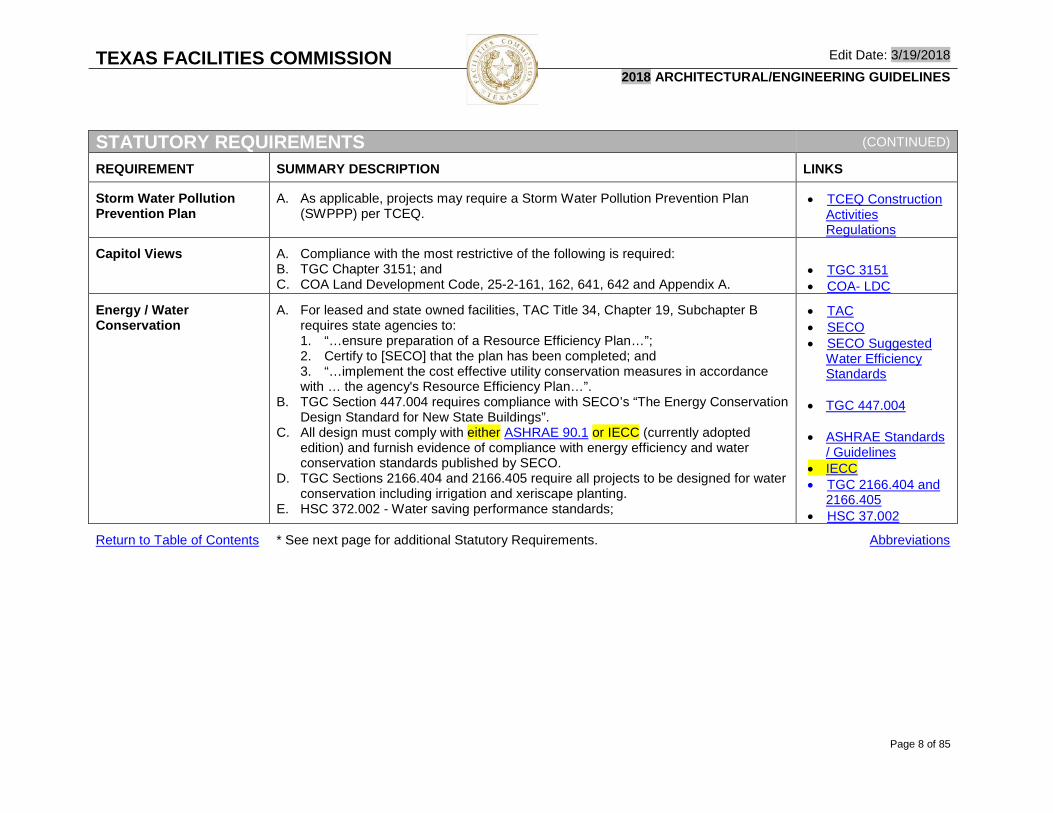
Storm Water Pollution Prevention Plan
A. As applicable, projects may require a Storm Water Pollution Prevention Plan (SWPPP) per TCEQ.
• TCEQ Construction Activities Regulations
Capitol Views A. Compliance with the most restrictive of the following is required: B. TGC Chapter 3151; and C. COA Land Development Code, 25-2-161, 162, 641, 642 and Appendix A.
• TGC 3151 • COA- LDC
Energy / Water Conservation
A. For leased and state owned facilities, TAC Title 34, Chapter 19, Subchapter B requires state agencies to: 1. “…ensure preparation of a Resource Efficiency Plan…”; 2. Certify to [SECO] that the plan has been completed; and 3. “…implement the cost effective utility conservation measures in accordance with … the agency's Resource Efficiency Plan…”.
B. TGC Section 447.004 requires compliance with SECO’s “The Energy Conservation Design Standard for New State Buildings”.
C. All design must comply with either ASHRAE 90.1 or IECC (currently adopted edition) and furnish evidence of compliance with energy efficiency and water conservation standards published by SECO.
D. TGC Sections 2166.404 and 2166.405 require all projects to be designed for water conservation including irrigation and xeriscape planting.
E. HSC 372.002 - Water saving performance standards;
• TAC • SECO • SECO Suggested
Water Efficiency Standards
• TGC 447.004
• ASHRAE Standards
/ Guidelines • IECC • TGC 2166.404 and
2166.405 • HSC 37.002
Return to Table of Contents * See next page for additional Statutory Requirements. Abbreviations

TEXAS FACILITIES COMMISSION Edit Date: 3/19/2018 2018 ARCHITECTURAL/ENGINEERING GUIDELINES
Page 9 of 85
STATUTORY REQUIREMENTS (CONTINUED)
REQUIREMENT SUMMARY DESCRIPTION LINKS
Energy Efficient Architectural and Engineering Design Alternatives Evaluation
A. TGC 2166.401 and 2166.403 - All projects, including new construction and alteration and repair projects where all or part of an energy system, energy source, or energy-consuming equipment is installed or replaced require a written economic feasibility evaluation of incorporating energy alternatives and energy-efficient architectural and engineering design into the building's design and proposed energy system. 1. Alternative Energy is defined as a renewable energy resource including solar
energy, biomass energy, geothermal energy, and wind energy. 2. SECO must approve any methodology or electronic software used in the
analysis. 3. The evaluation must identify the best energy alternative for each function of
the project over the economic life of the building considering costs and benefits of implementing alternative design practices and energy systems for all or part of each function relative to the use of conventional design practices and energy systems.
4. The evaluation must be made available to the public and presented at an open meeting.
5. If alternative designs or energy systems are determined to be economically feasible, the alternative design or system must be incorporated into the project.
• TGC 2166.401
• TGC 2166.403 • SECO
Return to Table of Contents * See next page for additional Statutory Requirements. Abbreviations

TEXAS FACILITIES COMMISSION Edit Date: 3/19/2018 2018 ARCHITECTURAL/ENGINEERING GUIDELINES
Page 10 of 85
STATUTORY REQUIREMENTS (CONTINUED)
REQUIREMENT SUMMARY DESCRIPTION LINKS
Combined Heating and Power (CHP) System
A. TGC 2311.002 – For economic development programs involving both state and local governments, new construction and extensive HVAC equipment renovations to critical governmental facilities require evaluation of the economic feasibility (over a 20 year period) of equipping the facility with a Combined Heating and Power (CHP) system. 1. A critical government facility is defined as a building owned by the state or a
political subdivision of the state that is expected to: a. Be continuously occupied; b. Maintain operations for at least 6,000 hours each year; c. Have a peak electricity demand exceeding 500 kilowatts; and d. Serve a critical public health or public safety function during a natural
disaster or other emergency situation that may result in a widespread power outage, including a: i. Command and control center; ii. Shelter; iii. Prison or jail; iv. Police or fire station; v. Communications or data center; vi. Water or wastewater facility; vii. Hazardous waste storage facility; viii. Biological research facility ix. Hospital; or x. Food preparation or food storage facility.
• TGC 2311.002
Return to Table of Contents * See next page for additional Statutory Requirements. Abbreviations

TEXAS FACILITIES COMMISSION Edit Date: 3/19/2018 2018 ARCHITECTURAL/ENGINEERING GUIDELINES
Page 11 of 85
STATUTORY REQUIREMENTS (CONTINUED)
REQUIREMENT SUMMARY DESCRIPTION LINKS
Exterior Lighting/Lighting Pollution (HSC 425)
A. Health and Safety Code, Title 5, Subtitle F, Chapter 425 requires outdoor lighting fixtures to be cutoff type luminaires under specific circumstances.
• HSC 425
Codes and Standards A. The most restrictive requirements of the following codes and standards will govern: 1. NFPA 101 Life Safety Code - Latest adopted edition per SFMO (TGC
417.008(e) establishes the SFMO as the AHJ for fire safety in all state owned buildings).
2. International Code Council (ICC) family of codes (latest published editions). 3. NFPA 70: National Electrical Code (latest published edition). 4. NFPA 70E: Standard for Electrical Safety in the Workplace; 5. ASHRAE 90.1: Energy Conservation Design Standard for State-Funded
Buildings or IECC (latest adopted edition per SECO); 6. Americans With Disabilities Act of 1990 (as currently amended);
a. 2010 ADA Standards for Accessible Design – 2010 Standards for State and Local Governments Title II;
7. TGC Chapter 469, Elimination of Architectural Barriers; a. 2012 Texas Accessibility Standards (and Technical Memoranda).
B. State of Texas properties are not subject to municipal or local codes, however TFC projects should be generally consistent with local land use practices. Cooperation with local services such as fire, watershed and utilities is advantageous to TFC projects.
• TGC 417.008 • NFPA 101 • NFPA 101 - SFMO
Adoption • ICC Store • ICC Public Access • NFPA 70 (NEC) • NFPA 70E • ASHRAE Standards
/ Guidelines • ASHRAE 90.1 /
IECC – SECO Adoption
• ADA Standards • TGC 469 • TAS Standards • Architectural
Barriers Technical Memoranda
Return to Table of Contents * See next page for additional Statutory Requirements. Abbreviations

TEXAS FACILITIES COMMISSION Edit Date: 3/19/2018 2018 ARCHITECTURAL/ENGINEERING GUIDELINES
Page 12 of 85
STATUTORY REQUIREMENTS (CONTINUED)
REQUIREMENT SUMMARY DESCRIPTION LINKS
Hazardous Materials A. Prior to demolition or construction efforts on existing facilities; a. TAC, Title 25, Part 1, Chapter 295, Subchapter C, Rule 295.34 requires
building owners to: i. Survey the facility for asbestos-containing material (ACM); ii. Abate all asbestos-containing building material (ACBM) that could
foreseeably be disturbed in the area to be renovated; and iii. Perform abatement in accordance with the Federal National Emission
Standard for Asbestos (40 CFR, Chapter 61, Subpart M) b. Obtain certification by a licensed engineer or architect that:
i. In the engineer's or architect's professional opinion, all parts of the building affected by the planned renovation or demolition do not contain asbestos.”
ii. Certification may be based on: (a) Current or previous surveys and reports; (b) Material safety data sheets for the materials used in
(i) The original construction; and (ii) The subsequent renovations or alterations of all parts of the
building affected by the planned renovation or demolition.
• TAC, 25,1, 295, C, 295.34
Uniform and Supplementary General Conditions
A. TGC Chapter 2166.302 requires TFC to adopt “…uniform general conditions to be incorporated into all building construction contracts made by the state”. 1. TFC’s Supplementary General Conditions modify the UGC and are required by
TFC to also be incorporated into all TFC construction contracts. 2. TFC’s currently adopted UGC and SGC are available on the TFC website.
B. TFC has also developed Special Conditions that may be incorporated in construction contracts at the discretion of TFC. 1. TFC Special Conditions, when required, may be obtained through TFC’s PM.
• TGC 2166.302 • UGC / SGC
Site Inspections A. TGC Chapter 2166.351 - TFC is responsible for protecting the interests of the state during construction through appropriate levels of inspections, including requirements upon the PSP.
• TGC 2166.351
Return to Table of Contents Abbreviations

TEXAS FACILITIES COMMISSION Edit Date: 3/19/2018 2018 ARCHITECTURAL/ENGINEERING GUIDELINES
Page 13 of 85
SUBMISSION PROCEDURES
SUBMISSION PROCEDURES
PROCEDURE PSP ACTIONS REQUIRED LINKS
General A. TFC has adopted an electronic “Round Trip” review process intended to: 1. Maximize clarity of communications between TFC and PSPs; 2. Minimize document review turn-around time; and 3. Reduce the environmental impact created by the traditional method of
printing and transporting hard-copy documents. B. Submit all documentation required at each project milestone as required in this
section and in the Submission Milestones and Submission Content sections below.
C. Clearly indicate the appropriate Edit Date of the Guidelines / Standards applicable to the project being submitted for review.
• Round Trip Review Process • Submission Milestones
Electronic Documents (Soft Copy)
A. Drawings: At each submission milestone: 1. Publish, or Export drawing sheet views to “DWFX” format (do not scan or convert from PDF format); 2. Group sheets into separate files by design discipline using the following file
naming convention: TFC Project Number
TFC Project Name Submission Milestone Abbreviation
Design Discipline Abbreviation 00-000-0000_???_???_???
Underscore
B. BIM Models (for BIM projects): At each submission milestone: 1. Civil3D Files:
a. Update the “.adsk” file(s) exported from the Building Model(s); and b. W-Block out to “.dwg” file format and submit w-blocked “.dwg” file.
2. Revit Files (Model Files Only – “PD” through “BA” Milestones): a. Review and correct all warnings. b. “Synchronize” all Revit “Local Files” with their respective “Central Model
File” in TFC’s collaboration environment; c. Export the “Central Model File” to “.adsk” (only for projects that require
coordination with Civil3D files).
• Autodesk “DWF Writer” • Drawing Standards – Document
Organization • BIM Standards
Return to Table of Contents * See next page for additional Submission Procedure requirements. Abbreviations
TEXAS FACILITIES COMMISSION Edit Date: 3/19/2018 2018 ARCHITECTURAL/ENGINEERING GUIDELINES
Page 14 of 85
SUBMISSION PROCEDURES (CONTINUED)
PROCEDURE PSP ACTIONS REQUIRED LINKS
Electronic Documents
(Soft Copy)
(Continued)
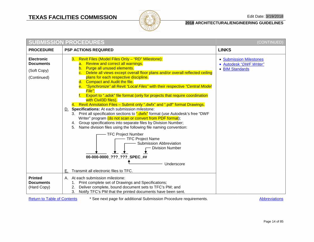
3. Revit Files (Model Files Only – “RD” Milestone): a. Review and correct all warnings. b. Purge all unused elements. c. Delete all views except overall floor plans and/or overall reflected ceiling
plans for each respective discipline. d. Compact and Audit the file. e. “Synchronize” all Revit “Local Files” with their respective “Central Model
File”; f. Export to “.adsk” file format (only for projects that require coordination
with Civil3D files). 4. Revit Annotation Files – Submit only “.dwfx” and “.pdf” format Drawings.
D. Specifications: At each submission milestone: 3. Print all specification sections to “.dwfx” format (use Autodesk’s free “DWF
Writer” program (do not scan or convert from PDF format); 4. Group specifications into separate files by Division Number; 5. Name division files using the following file naming convention:
TFC Project Number TFC Project Name
Submission Abbreviation Division Number
00-000-0000_???_???_SPEC_##
Underscore
E. Transmit all electronic files to TFC.
• Submission Milestones • Autodesk “DWF Writer” • BIM Standards
Printed Documents (Hard Copy)
A. At each submission milestone: 1. Print complete set of Drawings and Specifications; 2. Deliver complete, bound document sets to TFC’s PM; and 3. Notify TFC’s PM that the printed documents have been sent.
Return to Table of Contents * See next page for additional Submission Procedure requirements. Abbreviations

TEXAS FACILITIES COMMISSION Edit Date: 3/19/2018 2018 ARCHITECTURAL/ENGINEERING GUIDELINES
Page 15 of 85
SUBMISSION PROCEDURES (CONTINUED)
PROCEDURE PSP ACTIONS REQUIRED LINKS
Respond to Owner Comments
A. Upon receipt of TFC comments in DWFX and XLSX file formats: 1. Modify the BIM Model(s) or CADD file(s) as appropriate to address Owner
comments; 2. Export revised BIM/CADD sheet views to DWFX format; and 3. Provide written responses to TFC comments in the “Response” column of
the TFC Document Review Comments Log. B. Transmit all electronic files to TFC.
SECO Compliance Form(s)
A. Submit the completed compliance certification form and supporting documentation to the PM: 1. For downloadable compliance forms, follow the link to the right (SECO’s
Building Codes and Standards web page).
• SECO – Texas Design Standard Compliance Forms
Energy / Water Conservation Rebates
A. Identify Federal, State, and/or Local rebate programs applicable to the project. B. Develop and submit relevant/necessary application materials to the entity(ies)
offering rebates.
Accessibility Review and Inspection
A. Register project with TDLR and pay registration fee; B. Submit proof of registration and sealed Contract Documents to an RAS within
the allotted time; C. Pay the review fee; D. Respond in writing to the RAS regarding measures to be taken to address any
conditions found to be non-compliant and issue a formal Addendum correcting the deficiencies;
E. Schedule the accessibility inspection on or after the date of substantial completion;
F. Pay the inspection fee; G. Respond in writing to the RAS regarding measures to be taken to address any
conditions found to be non-compliant and issue a formal Change Proposal or directive.
H. Provide TFC’s PM with copies of all communications with the RAS.
• TDLR Online Registration • TDLR Fee Schedule • TDLR Document Submission
Requirements
Historical Status Determination and Compliance
A. If the Project Analysis indicates a requirement for THC review and approval, submit required documentation directly to THC in a timely manner.
• THC
Return to Table of Contents Abbreviations

TEXAS FACILITIES COMMISSION Edit Date: 3/19/2018 2018 ARCHITECTURAL/ENGINEERING GUIDELINES
Page 16 of 85
Round Trip Review Process Diagram
SUBMISSION PROCEDURES (CONTINUED)
PROCEDURE PSP ACTIONS REQUIRED LINKS
TCEQ Documentation
A. For projects where a SWPPP is required, submit the necessary documentation to TCEQ and pay all application and review fees.
• TCEQ
Roundtrip Review Process Diagram
• BIM Workflow Diagram
Return to Table of Contents Abbreviations

TEXAS FACILITIES COMMISSION Edit Date: 3/19/2018 2018 ARCHITECTURAL/ENGINEERING GUIDELINES
Page 17 of 85
SUBMISSION MILESTONES
SUBMISSION MILESTONES
PHASE MILESTONE DESCRIPTION SUBMISSION FORMAT
General A. Submit documentation for Owner review at each submission milestone listed below.
B. Individual project requirements (as determined by TFC) may dictate the need for fewer or additional submissions and submission format changes - confirm specific requirements with PM.
C. Submission content requirements are provided in the “Submission Content” portion of this document.
Assessment (PD) A. PD1 (Late Phase) – If required in PSP contract: 1. Substantially complete documentation of the work required in this
design phase. B. PD2 (End of Phase) – If required in PSP contract
1. Final documentation satisfactorily addressing Owner comments on previous submission.
• Number of printed and bound sets as defined in contract or as directed by PM; and
• Transmit electronic files to TFC.
Initial Conceptual Drawings / Schematic Design (SD)
A. SD1 (Late Phase) – If required in PSP contract: 1. Substantially complete documentation of the work required in this
design phase. B. SD2 (End of Phase) – If required in PSP contract:
1. Final documentation satisfactorily addressing Owner comments on previous submission.
• Number of printed and bound sets as defined in contract or as directed by PM;
• Transmit electronic files to TFC; and
• Number of mounted copies of renderings as defined in contract or as directed by PM: o Image width 24” (min.) o Board width 30” (min.)
Design Development (DD)
A. DD1 (Late of Phase): 1. Substantially complete, coordinated documentation of the work required
in this design phase.
B. DD2 (End of Phase): 1. Final documentation satisfactorily addressing Owner comments on
previous submission.
• Number of printed and bound sets as defined in contract or as directed by PM; and
• Transmit electronic files to TFC.
Return to Table of Contents Abbreviations

TEXAS FACILITIES COMMISSION Edit Date: 3/19/2018 2018 ARCHITECTURAL/ENGINEERING GUIDELINES
Page 18 of 85
SUBMISSION MILESTONES (CONTINUED)
PHASE MILESTONE DESCRIPTION SUBMISSION FORMAT
Contract Documents (CD)
A. CD65 (Mid-Phase): 1. In progress documentation of all work required in this design phase. 2. Submission occurs at approximately the mid-point of this design phase. 3. Satisfactorily address Owner comments on previous submissions.
B. CD90 (Late Phase): 1. Substantially complete, coordinated documentation of all work required
in this design phase. 2. Satisfactorily address Owner comments on previous submissions.
C. CD100 (End of Phase): 1. Complete, sealed and signed, coordinated documentation of all work
required in this design phase. 2. Last Submission prior to Bid Documents. 3. Satisfactorily address Owner comments on previous submissions.
• Number of printed and bound sets as defined in contract or as directed by PM; and
• Transmit electronic files to TFC.
Contract Bidding and Award (BA)
A. BA - Bid Documents: 1. Satisfactorily address Owner comments on previous submission
materials. 2. Complete, fully coordinated Bid Documents with:
a. Professional seals affixed; and b. Signatures of all responsible design professionals.
3. Submit all necessary documentation to authorities having jurisdiction.
• Number of printed and bound sets as defined in contract or as directed by PM; and
• Transmit electronic files to TFC.
Construction Phase - General Administration of Construction Contracts (CA)
A. CA – Construction Phase Documents: 1. Consolidated set of sealed / signed documents incorporating all
Addenda and Clarifications issued during the bidding phase.
• Number of printed and bound sets as defined in contract or as directed by PM;
• Transmit electronic files to TFC.
Warranty (RD) A. RD – Record Documents: 1. Documentation (incorporating all Contractor’s mark-ups) of as-
constructed conditions.
• Number of printed and bound sets as defined in contract or as directed by PM; and
• Transmit electronic files to TFC.
Return to Table of Contents Abbreviations

TEXAS FACILITIES COMMISSION Edit Date: 3/19/2018 2018 ARCHITECTURAL/ENGINEERING GUIDELINES
Page 19 of 85
SUBMISSION CONTENT Assessment (Pre-design)
SUBMISSION CONTENT – ASSESSMENT (PREDESIGN - PD1 & PD2) (Abbreviated from Phase previously identified as Mobilization/Predesign)
DOCUMENT PSP ACTIONS REQUIRED (Subject to PSP Contract Modifications) FILE FORMAT
General A. Confirm or modify to reflect current project requirements and/or conditions: 1. Prior programming decisions provided by TFC such as but not limited to:
a. Project Analysis; b. Construction Budget; and c. Project Schedule.
2. Other information provided by TFC: a. Existing conditions archival documents; b. Applicable codes and regulatory requirements.
Executive Summary Report
A. Document relevant data collected, analyses performed, and design concepts and criteria recommended.
• Autodesk Design Review (.dwfx)
• TFC Accepted Software Versions Project Objective
Statement A. State whether the project follows or deviates from the Project Analysis and
why.
Project Implementation Plan
A. Outline the method by which the project will be organized and delivered: 1. BIM or CADD.
Schedule for Delivery of Services
A. Identify all project milestones including: 1. Design Document Submission Dates and Review Periods for Owner and
Jurisdictional Authorities: a. Submission; b. Review; c. Revision; and d. Authorization to Proceed.
2. Critical Meetings / Presentations; 3. Bid Package Issuance Date(s); 4. Bid Opening Date(s); 5. Construction start, punch inspection, and substantial completion; 6. Owner Move-in; and 7. Warranty Period.
Return to Table of Contents * See next page for additional Mobilization / Pre-design Submission Content. Abbreviations

TEXAS FACILITIES COMMISSION Edit Date: 3/19/2018 2018 ARCHITECTURAL/ENGINEERING GUIDELINES
Page 20 of 85
SUBMISSION CONTENT – ASSESSMENT (PREDESIGN - PD1 & PD2) (Abbreviated from Phase previously identified as Mobilization/Predesign)
(CONTINUED)
DOCUMENT PSP ACTIONS REQUIRED (Subject to PSP Contract Modifications) FILE FORMAT
Technical Requirements List
A. Submit a list of all applicable: 1. Codes and Standards; 2. Jurisdictional Authorities; 3. Utility Providers; 4. Environmental factors affecting the project design (including EPA and
TCEQ fuel storage requirements); 5. Applicable TFC Technical and Design Standards (Reference the
applicable Edit Date); 6. Applicable Using Agency(ies) Technical and Design Standards (Reference
the applicable Edit Date).
Existing Facilities Condition Analysis
A. Describe the condition of the existing building and / or site features as appropriate to the project: 1. Provide a list of all items to be relocated or reused; 2. Indicate all features that do not meet Programmatic or Technical
Requirements; 3. Describe specific deficiencies for each non-compliant feature; and 4. Propose strategies for reconciling the deficiencies.
Return to Table of Contents Abbreviations

TEXAS FACILITIES COMMISSION Edit Date: 3/19/2018 2018 ARCHITECTURAL/ENGINEERING GUIDELINES
Page 21 of 85
Schematic Design
SUBMISSION CONTENT – SCHEMATIC DESIGN (SD1 & SD2) (Combined with portions of Phase previously identified as Mobilization/Predesign)
DOCUMENT PSP ACTIONS REQUIRED (Subject to PSP Contract Modifications) FILE FORMAT
General A. Describe the proposed conceptual design, scale, and relationships among the major components of the Project.
Executive Summary Report
A. Revise the previous report to reflect current project conditions. B. Include (as applicable to the project):
1. An illustration of key conceptual issues; 2. Stacking and Blocking diagrams showing efficient use of space; 3. Summary of site evaluation and regional data.
• Autodesk Design Review (.dwfx)
• TFC Accepted Software Versions
Schedule for Delivery of Services
A. Revise the previous Schedule to reflect any changes to anticipated task durations and milestone dates.
Initial Estimate of Probable Construction Cost
A. Adjust the TFC provided project budget to reflect updated program requirements with the following basis for Unit Costs: 1. Square footage calculations as measured from the SD Drawings:
a. Basis for Measurement: AIA Document D101 - Methods of Calculating the Area and Volume of Buildings;
2. Recent comparable projects of similar function, size, construction type, level of finish, and type of mechanical and electrical system(s);
3. Adjust unit costs for local bidding climate at time of projected bid date. B. Organize the estimate according to CSI Uniformat categories;
1. Include all applicable assemblies and systems. C. Include a list of items that are:
1. Not in the contract; or 2. Supplied by others.
D. Include contingencies for the following: 1. Scope escalation; 2. Development of unanticipated design elements; 3. Economic influences on cost escalation / fluctuation; and 4. Construction phase changes.
E. Identify cost variances between the Estimate and the established Construction Cost Limitation;
F. Propose strategies for reconciling the variances.
• Autodesk Design Review (.dwfx)
• TFC Accepted Software Versions
Return to Table of Contents * See next page for additional Mobilization / Pre-design Submission Content. Abbreviations

TEXAS FACILITIES COMMISSION Edit Date: 3/19/2018 2018 ARCHITECTURAL/ENGINEERING GUIDELINES
Page 22 of 85
SUBMISSION CONTENT – SCHEMATIC DESIGN (SD1 & SD2) (Combined with section previously identified as Mobilization/Predesign)
(CONTINUED)
DOCUMENT PSP ACTIONS REQUIRED (Subject to PSP Contract Modifications) FILE FORMAT
Technical Requirements List
A. Provide Plumbing Fixture Count Calculations based on Space Allocation Program below (if applicable to the project).
Room Data Sheets A. Provide the following information (as applicable to the project) for each programmed space: 1. Structural / Physical Isolation; 2. Hazardous Materials List (Types & Quantities); 3. Fire Separation; 4. Acoustical Performance; 5. Access Control / Monitoring; 6. Door Information:
a. Type(s); b. Size(s); c. Material(s); and d. Hardware Functions.
7. Finish Materials; 8. HVAC;
a. Temperature Range(s); b. Humidity Control; c. Filtering;
9. HVAC and Lighting controls requirements; 10. Lighting Level (Foot Candles); 11. Electrical Power; 12. Data / Telecommunications; 13. Plumbing; 14. Re-used Items; and 15. Special Considerations.
• Autodesk Design Review (.dwfx)
• TFC Accepted Software Versions
Return to Table of Contents * See next page for additional Mobilization / Pre-design Submission Content. Abbreviations

TEXAS FACILITIES COMMISSION Edit Date: 3/19/2018 2018 ARCHITECTURAL/ENGINEERING GUIDELINES
Page 23 of 85
SUBMISSION CONTENT – SCHEMATIC DESIGN (SD1 & SD2) (Combined with section previously identified as Mobilization/Predesign)
(CONTINUED)
DOCUMENT PSP ACTIONS REQUIRED (Subject to PSP Contract Modifications) FILE FORMAT
Layout Diagrams A. Provide the following graphic information (as applicable to the project) for each programmed space: 1. Diagrammatic configuration of individual and/or groups of spaces; 2. Dimensional Requirements (absolute, minimum, and/or maximum); 3. Partition Type(s):
a. Height; b. Fire Rating; and c. Sound Rating.
4. Door Location(s); 5. Window Location(s); 6. Furniture / Casework / Equipment / Relocated Items;
a. Type(s) / Size(s); b. Location(s); c. Mounting Heights; and d. Clearance Requirements.
7. Ceiling: a. Height(s); and b. Material(s).
8. Lighting: a. Fixture Type(s) / Location(s); and b. Switch / Controls Type(s) / Location(s).
9. Power / Data / Communications: a. Outlet Type(s) / Location(s); and b. Mounting Heights.
• Autodesk Design Review (.dwfx)
AND • Autodesk Autocad • TFC Accepted Software
Versions
Adjacency & Stacking Diagrams
A. Provide 2D and 3D diagrams illustrating horizontal and vertical relationships between spaces and between departments.
• Autodesk Design Review (.dwfx)
Return to Table of Contents * See next page for additional Mobilization / Pre-design Submission Content. Abbreviations

TEXAS FACILITIES COMMISSION Edit Date: 3/19/2018 2018 ARCHITECTURAL/ENGINEERING GUIDELINES
Page 24 of 85
SUBMISSION CONTENT – SCHEMATIC DESIGN (SD1 & SD2) (Combined with section previously identified as Mobilization/Predesign)
(CONTINUED)
DOCUMENT PSP ACTIONS REQUIRED (Subject to PSP Contract Modifications) FILE FORMAT
Space Allocation Program
A. Use TFC standard “Space Allocation Program” to report the following for each programmed space (if applicable to the project): 1. Provide square footages as measured from drawings below;
a. Use AIA Document D101 - Methods of Calculating the Area and Volume of Buildings.
2. Building-wide information: a. Building Grossing Factor; b. Total Gross Building Area.
3. Departmental Information: a. Using Agency Department Name and ID Number: b. Common Areas;
i. Circulation Spaces (vertical and Horizontal); ii. Maintenance and Support Spaces:
(a) Restrooms and Showers; (b) Housekeeping; (c) Shipping and Receiving.
iii. Building Service Spaces: (a) Mechanical; (b) Electrical; (c) Data / Communications; (d) Plumbing;
4. Space Information: a. Space Name and ID Number; b. Space Type; c. Number of occupants; d. Net area and dimensions (length, width, and ceiling height) e. Number Required. f. Total occupancy (number x occupants); g. Total Net Area (number x net area); h. Departmental Grossing Factor; i. Departmental Gross Area (factor x total net); and
• Autodesk Design Review (.dwfx)
• TFC Accepted Software Versions
Return to Table of Contents * See next page for additional Mobilization / Pre-design Submission Content. Abbreviations

TEXAS FACILITIES COMMISSION Edit Date: 3/19/2018 2018 ARCHITECTURAL/ENGINEERING GUIDELINES
Page 25 of 85
SUBMISSION CONTENT – SCHEMATIC DESIGN (SD1 & SD2) (Combined with section previously identified as Mobilization/Predesign)
(CONTINUED)
DOCUMENT PSP ACTIONS REQUIRED (Subject to PSP Contract Modifications) FILE FORMAT
BIM Model A. Provide all BIM model and annotation files (and all linked files) containing all features of the project as indicated in the Drawing requirements below.
B. See BIM Standards for more information.
• Autodesk Navisworks (.nwd and all linked .nwf files)
• Autodesk Civil3D • Autodesk Revit
Drawings – SD1 A. Provide drawings describing the proposed design containing the following (as applicable to the project): 1. Project information;
a. TFC Project Name and TFC Project Number; b. Project address / Location map; c. Team members; d. Drawing index; e. Submission Milestone.
2. Site: a. Existing conditions site survey; b. Property lines, setbacks, easements, and view corridor restrictions
(existing and proposed including metes and bounds); c. Building locations; d. Adjacent roadways; e. Site Demolition; f. Public transportation stops; g. Vehicular and pedestrian circulation paths and parking; h. Service vehicle access; i. Landscape planting strategies; j. Basic grading and soil retention strategies; k. Pools, ponds, and other water features; l. Storm water management strategies (as applicable) for:
i. Rainwater collection; ii. Drainage, Filtration, and Detention.
m. Utility service locations and routing (existing and proposed);
• Autodesk Design Review (.dwfx)
AND
• Autodesk Autocad
• TFC Accepted Software Versions
Return to Table of Contents * See next page for additional Mobilization / Pre-design Submission Content. Abbreviations

TEXAS FACILITIES COMMISSION Edit Date: 3/19/2018 2018 ARCHITECTURAL/ENGINEERING GUIDELINES
Page 26 of 85
SUBMISSION CONTENT – SCHEMATIC DESIGN (SD1 & SD2) (Combined with section previously identified as Mobilization/Predesign)
(CONTINUED)
DOCUMENT PSP ACTIONS REQUIRED (Subject to PSP Contract Modifications) FILE FORMAT
Drawings – SD1 (Continued)
n. Major exterior equipment locations and sizes such as: i. Diesel generators; ii. Electrical enclosures; iii. Communications towers; and iv. Fuel storage facilities.
3. Floor Plan(s): a. Overall building configuration; b. Arrangement of programmed spaces; c. Space names and numbers coordinated with Space Allocation
Program; d. Horizontal and vertical circulation elements; e. Furniture layouts; f. Roof Plan: Basic configuration; Major slopes defined;
4. Major exterior Building Elevations: a. Design vocabulary; b. Basic materials; c. Door and window openings; d. Floor-to-floor heights; e. Line of finished grade.
5. Building Section(s) as needed to illustrate unique volumetric characteristics of the proposed design.
6. MEP: a. One Line diagrams; b. Major equipment locations and sizes identified such as:
i. Chillers; ii. Fire Pump; iii. Emergency Generator; iv. Automatic Transfer Switch (ATS); v. Uninterruptable Power Supply (UPS); and vi. Switchboards and Panels vii. Building Management System (BMS).
• Autodesk Design Review (.dwfx)
AND
• Autodesk Autocad
• TFC Accepted Software Versions
Return to Table of Contents * See next page for additional Mobilization / Pre-design Submission Content. Abbreviations

TEXAS FACILITIES COMMISSION Edit Date: 3/19/2018 2018 ARCHITECTURAL/ENGINEERING GUIDELINES
Page 27 of 85
SUBMISSION CONTENT – SCHEMATIC DESIGN (SD1 & SD2) (Combined with section previously identified as Mobilization/Predesign)
(CONTINUED)
DOCUMENT PSP ACTIONS REQUIRED (Subject to PSP Contract Modifications) FILE FORMAT
Drawings – SD1 (Continued)
8. Other drawings if needed to illustrate important design features. 9. Legends and symbols: All disciplines.
•
Drawings – SD2 A. Provide final presentation documents reflecting satisfactory responses to TFC comments regarding the SD1 documents; and
B. Renderings (If applicable to the project): Photo-realistic color perspectives of the exterior of the proposed building(s) in context with their surroundings:
a. One bird’s-eye” view (or other view as determined by TFC); and b. One eye-level view that includes the main façade.
• Renderings: 600 DPI (.png)
Specifications A. List primary materials and building systems: 1. Format: Outline using TFC template.
B. See appendices for technical standards
• Autodesk Design Review (.dwfx)
Energy Efficient Architectural and Engineering Design Alternatives Evaluation
A. Develop in greater detail and verify results of the Energy Efficient Architectural and Engineering Design Alternatives Evaluation provided by TFC at the beginning of the Mobilization and Pre-design Phase. 1. Address all requirements of TGC Sections 2166.153, 2166.401, 2166.403,
and 2166.408 such as: a. Identify and compare the benefits and disadvantages of potential
alternatives including: i. Environmental impact (both initially and over the project’s life
cycle); ii. Economic Impact (both initially and over the project’s life cycle).
b. Recommend the best alternatives considering both economic and environmental life-cycle costs and benefits.
2. Determine the viability of accommodating future alternative energy system installations by providing anticipated floor space and service pathways in the current design.
B. When using BIM, utilize data embedded in the BIM model in conjunction with other appropriate energy modeling software and web-based weather/energy databases to perform this analysis. 1. Modeling shall comply with ASHRAE 90.1 Appendix G Performance
Rating Method or IECC (currently adopted edition).
• Autodesk Design Review (.dwfx)
• TFC Accepted Software Versions
Return to Table of Contents * See next page for additional Mobilization / Pre-design Submission Content. Abbreviations

TEXAS FACILITIES COMMISSION Edit Date: 3/19/2018 2018 ARCHITECTURAL/ENGINEERING GUIDELINES
Page 28 of 85
SUBMISSION CONTENT – SCHEMATIC DESIGN (SD1 & SD2) (Combined with section previously identified as Mobilization/Predesign)
(CONTINUED)
DOCUMENT PSP ACTIONS REQUIRED (Subject to PSP Contract Modifications) FILE FORMAT
Narratives / Analyses / Evaluations
A. Provide written analyses, assumptions, and recommendations to be included as the Basis of Design for materials, systems, equipment and energy sources for the following (as applicable to the project): 1. HVAC Systems:
a. Coordination events schedule; b. Load Estimates (order of magnitude); c. Strategy for resolving conflicts between:
i. Project criteria; ii. Design / Technical Standards; and iii. Code Requirements.
2. Plumbing Systems: a. Domestic and Fire water pressure and line size requirements; b. Wastewater:
i. Discharge capacity; ii. Lift station requirements (if applicable).
3. Energy Sources: a. Primary Utility; b. Emergency / Standby Power;
4. Energy Conservation; a. Alternative Energy Sources b. Metering of:
i. Electrical power and lighting; ii. Natural Gas; iii. Domestic, irrigation, and process water.
c. Artificial lighting and daylighting systems and controls strategies; d. Energy Consumption: Anticipated total monthly building energy usage.
5. Smoke and emission control systems; 6. Fire and Life Safety systems; 7. Building Management System.
• Autodesk Design Review (.dwfx)
• TFC Accepted Software Versions
Return to Table of Contents * See next page for additional Mobilization / Pre-design Submission Content. Abbreviations

TEXAS FACILITIES COMMISSION Edit Date: 3/19/2018 2018 ARCHITECTURAL/ENGINEERING GUIDELINES
Page 29 of 85
SUBMISSION CONTENT – SCHEMATIC DESIGN (SD1 & SD2) (Combined with section previously identified as Mobilization/Predesign)
(CONTINUED)
DOCUMENT PSP ACTIONS REQUIRED (Subject to PSP Contract Modifications) FILE FORMAT
Narratives / Analyses (Continued
B. Recommend the most appropriate assemblies/equipment/systems that address project specific needs including: 1. Operating Concepts: Critical ideas behind the recommended design
solution and the rationale which supports that solution: a. Statutory and regulatory requirements;
i. Include analysis and recommendation regarding use of ASHRAE 90.1 or IECC.
b. Interrelationships between spaces (both interior and exterior); c. Life safety features; d. Material and building systems selections; e. Artificial Lighting and Daylighting strategies for each type of space; f. Environmental quality (both interior and exterior); g. Emergency operations
2. Water conservation/efficiency (SECO Water Conservation Standard); 3. Foundation and Structural Frame Systems:
a. Brief analysis of soils report as related to system selection; b. Comparison of benefits and disadvantages of potential systems;
4. Building Envelope: a. Brief description of existing and new building envelope assemblies (as
applicable); 5. Comparison of the proposed envelope assemblies to the ASHRAE 90.1
Appendix G baseline or IECC -(currently adopted edition). 6. Indoor Air Quality and Pollutant Source Control Plan: Include specific
strategies for addressing the TFC: a. Design Standards – Indoor Air Quality sections; and b. Technical Standards – 01 81 19 - Indoor Air Quality Requirements.
• Autodesk Design Review (.dwfx)
• TFC Accepted Software Versions
Return to Table of Contents * See next page for additional Mobilization / Pre-design Submission Content. Abbreviations

TEXAS FACILITIES COMMISSION Edit Date: 3/19/2018 2018 ARCHITECTURAL/ENGINEERING GUIDELINES
Page 30 of 85
SUBMISSION CONTENT – SCHEMATIC DESIGN (SD1 & SD2) (Combined with section previously identified as Mobilization/Predesign)
(CONTINUED)
DOCUMENT PSP ACTIONS REQUIRED (Subject to PSP Contract Modifications) FILE FORMAT
Narratives / Analyses (Continued)
7. MEP, Fire Alarm, Fire Protection, and Security Systems Narratives: a. Brief description of existing and new systems/conditions (as
applicable); b. List of assumptions and unknowns; c. Design criteria; d. Benefits and disadvantages of potential equipment/systems: e. Comparison of the proposed systems to the ASHRAE 90.1 Appendix
G baseline or IECC (currently adopted edition). i. Target Efficiency: 15% more efficient than baseline building. ii. Maximum Payback Period: 5 years.
f. Address preparation of electrical breaker coordination study and NFPA 70E labeling requirements.
C. Estimate above ceiling space requirements for all systems. D. List all materials / systems yet to be determined.
• Autodesk Design Review (.dwfx)
• TFC Accepted Software Versions
Return to Table of Contents Abbreviations

TEXAS FACILITIES COMMISSION Edit Date: 3/19/2018 2018 ARCHITECTURAL/ENGINEERING GUIDELINES
Page 31 of 85
Design Development
SUBMISSION CONTENT – DESIGN DEVELOPMENT (DD1 & DD2)
DOCUMENT PSP ACTIONS REQUIRED (Subject to PSP Contract Modifications) FILE FORMAT
General A. Illustrate and coordinate all important aspects of the Project. B. Resolve all major issues that could cause significant restudy during the CD
phase.
Executive Summary Report
A. Revise the previous report to reflect current project conditions. • Autodesk Design Review (.dwfx)
• TFC Accepted Software Versions
Schedule for Delivery of Services
A. Revise the previous Schedule to reflect any changes to anticipated task durations and milestone dates.
Estimate of Probable Project Construction Cost
A. Revise the previous estimate based on: 1. New information regarding proposed building systems and materials; and
a. Quantities take-off as measured from the DD Drawings. B. Retain the CSI Uniformat organization. C. Include the same types of contingencies as in the previous phase.
Space Allocation Program
A. Same as SD submission content above plus the following: 1. Add room numbers (from drawings below).
BIM Model A. Same as SD submission content above plus the following: 1. All physical features of the project as indicated in the Drawing
requirements below. 2. Prior to document submission, use conflict checking software to:
a. Identify and resolve clashes between all disciplines and specialties included on the project: i. Hard clashes between the various elements; and ii. Soft clashes between any element(s) and required clearances.
b. Submit the report generated by the checking software indicating that conflicts have been resolved.
B. See BIM Standards for more information.
• Autodesk Navisworks (.nwd and all linked .nwf files)
• Autodesk Civil3D • Autodesk Revit
Return to Table of Contents * See next page for additional Design Development Submission Content. Abbreviations

TEXAS FACILITIES COMMISSION Edit Date: 3/19/2018 2018 ARCHITECTURAL/ENGINEERING GUIDELINES
Page 32 of 85
SUBMISSION CONTENT – DESIGN DEVELOPMENT (DD1 & DD2) (CONTINUED)
DOCUMENT PSP ACTIONS REQUIRED (Subject to PSP Contract Modifications) FILE FORMAT
Drawings A. Same as SD submission content above plus the following(as applicable to the project): 1. Detailed code compliance information (all disciplines);
a. Reference codes; b. Jurisdictional authorities; c. Building information:
i. Construction type; ii. Occupancy(ies); iii. Fire suppression systems;
d. Code compliance calculations indicating both allowable/required and proposed conditions: i. Height and area; ii. Exiting; iii. Plumbing fixture count;
e. Life safety plans: i. Occupant loading; ii. Exiting;
f. Fire rated walls and partitions clearly identified. 2. Site:
a. Accessible Route; b. Landscape planting and irrigation plans; c. Site furnishings and appurtenances; d. Planter, wall, and fence elevations; e. Grading Plan (with critical spot elevations); f. Utility Plan; g. Typical details;
i. Planting; ii. Paving and hardscape; iii. Retaining walls and planters; iv. Bollards; v. Utilities.
h. Parking counts;
• Autodesk Design Review (.dwfx)
AND • Autodesk Autocad • TFC Accepted Software
Versions
Return to Table of Contents * See next page for additional Design Development Submission Content. Abbreviations

TEXAS FACILITIES COMMISSION Edit Date: 3/19/2018 2018 ARCHITECTURAL/ENGINEERING GUIDELINES
Page 33 of 85
SUBMISSION CONTENT – DESIGN DEVELOPMENT (DD1 & DD2) (CONTINUED)
DOCUMENT PSP ACTIONS REQUIRED (Subject to PSP Contract Modifications) FILE FORMAT
Drawings (Continued)
3. Floor Plan(s): a. Room and door numbers; b. Reference keys:
i. Enlarged plans; ii. Partition types; iii. Exterior and Interior elevations; iv. Building and Wall sections; and v. Plan details.
c. Dimensions: i. Massing; ii. Structural Grid; and iii. Partitions.
4. Furniture layouts. 5. Roof:
a. All slopes indicated; b. Major equipment locations identified; c. Major MEP penetrations coordinated; d. Reference keys:
i. Building and Wall sections. 6. Exterior Building Elevations:
a. All building faces; b. Material patterns; c. Vertical dimensions; d. Structural grid; e. Building section and wall section keys;
7. Major MEP penetrations coordinated. 8. Enlarged floor plans;
a. Typical room layouts (as applicable to project type); b. Restrooms / Showers; c. Stairs, ramps, and elevators; and d. Other specialty spaces as appropriate to the proposed design.
•
Return to Table of Contents * See next page for additional Design Development Submission Content. Abbreviations

TEXAS FACILITIES COMMISSION Edit Date: 3/19/2018 2018 ARCHITECTURAL/ENGINEERING GUIDELINES
Page 34 of 85
SUBMISSION CONTENT – DESIGN DEVELOPMENT (DD1 & DD2) (CONTINUED)
DOCUMENT PSP ACTIONS REQUIRED (Subject to PSP Contract Modifications) FILE FORMAT
Drawings (Continued)
9. Interior / Millwork Elevations; 10. Door and frame information:
a. Schedule (including hardware set assignments); b. Types; and c. Typical head, jamb, and sill details.
11. Hardware Schedule (to be provided in the drawing set, not in the Project Manual): a. Generic functions only: b. Basis of Design: Include in specifications.
12. Room Finish Schedule (by individual space); 13. Reflected Ceiling Plans; 14. Architectural Details (typical); 15. Structural:
a. Foundation and Framing Plans; b. Loading assumptions and member sizes; c. Important details.
16. Metering: a. Meter locations; b. Types of data being metered.
17. Mechanical: a. Site information (if applicable); b. Equipment and thermostat locations; c. Primary distribution routing and sizes: d. Secondary distribution routing; e. Supply devices with CFM; f. Riser diagrams; g. Major duct penetrations (Locations and sizes); and h. Equipment selections / Schedules.
• Autodesk Design Review (.dwfx)
AND • Autodesk Autocad • TFC Accepted Software
Versions
Return to Table of Contents * See next page for additional Design Development Submission Content. Abbreviations

TEXAS FACILITIES COMMISSION Edit Date: 3/19/2018 2018 ARCHITECTURAL/ENGINEERING GUIDELINES
Page 35 of 85
SUBMISSION CONTENT – DESIGN DEVELOPMENT (DD1 & DD2) (CONTINUED)
DOCUMENT PSP ACTIONS REQUIRED (Subject to PSP Contract Modifications) FILE FORMAT
Drawings (Continued)
16. Electrical: a. Site information (if applicable); b. Equipment locations; c. Floor Plans:
i. Lighting layout; ii. Lighting Footcandle Levels (interior and exterior) including tables
showing: (a) Maximum, average, and minimum lighting levels; (b) Maximum-to-Average ratio; (c) Average-to-Minimum ratio.
iii. Power (panel and receptacle locations); iv. Lightning Protection and Grounding; v. Data / Communications (indicating drop locations); vi. Fire Alarm (FACP and device locations); vii. Security Systems (access control, CCTV, equipment schedules).
d. Riser diagrams: i. Expected panels and transformers; ii. Cable and conduit information.
e. Equipment and Fixture Schedules; f. Lighting Density Schedule for main areas: Demonstrate compliance
with ASHRAE 90.1 or IECC -(Currently adopted edition). 17. Plumbing and Fire Protection:
a. Site information (if applicable); b. Equipment and fixture locations;
i. Supply, waste, vent, and storm routing with flow rate quantities. c. Riser diagrams; d. Major piping penetrations and risers (Locations and sizes); and
18. Equipment and Fixture Schedules.
• Autodesk Design Review (.dwfx)
AND • Autodesk Autocad • TFC Accepted Software
Versions
Return to Table of Contents * See next page for additional Design Development Submission Content. Abbreviations
TEXAS FACILITIES COMMISSION Edit Date: 3/19/2018 2018 ARCHITECTURAL/ENGINEERING GUIDELINES
Page 36 of 85
SUBMISSION CONTENT – DESIGN DEVELOPMENT (DD1 & DD2) (CONTINUED)
DOCUMENT PSP ACTIONS REQUIRED (Subject to PSP Contract Modifications) FILE FORMAT
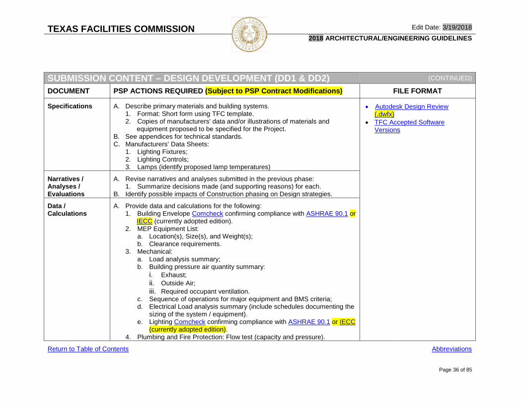
Specifications A. Describe primary materials and building systems. 1. Format: Short form using TFC template. 2. Copies of manufacturers' data and/or illustrations of materials and
equipment proposed to be specified for the Project. B. See appendices for technical standards. C. Manufacturers’ Data Sheets:
1. Lighting Fixtures; 2. Lighting Controls; 3. Lamps (identify proposed lamp temperatures)
• Autodesk Design Review (.dwfx)
• TFC Accepted Software Versions
Narratives / Analyses / Evaluations
A. Revise narratives and analyses submitted in the previous phase: 1. Summarize decisions made (and supporting reasons) for each.
B. Identify possible impacts of Construction phasing on Design strategies.
Data / Calculations
A. Provide data and calculations for the following: 1. Building Envelope Comcheck confirming compliance with ASHRAE 90.1 or
IECC (currently adopted edition). 2. MEP Equipment List:
a. Location(s), Size(s), and Weight(s); b. Clearance requirements.
3. Mechanical: a. Load analysis summary; b. Building pressure air quantity summary:
i. Exhaust; ii. Outside Air; iii. Required occupant ventilation.
c. Sequence of operations for major equipment and BMS criteria; d. Electrical Load analysis summary (include schedules documenting the
sizing of the system / equipment). e. Lighting Comcheck confirming compliance with ASHRAE 90.1 or IECC
(currently adopted edition). 4. Plumbing and Fire Protection: Flow test (capacity and pressure).
Return to Table of Contents Abbreviations

TEXAS FACILITIES COMMISSION Edit Date: 3/19/2018 2018 ARCHITECTURAL/ENGINEERING GUIDELINES
Page 37 of 85
Contract Documents
SUBMISSION CONTENT – CONTRACT DOCUMENTS (CD65, CD90, & CD100)
DOCUMENT PSP ACTIONS REQUIRED (Subject to PSP Contract Modifications) FILE FORMAT
General A. Develop detailed and coordinated documents setting forth the requirements for the construction of the project.
Executive Summary Report
A. Revise the previous report to reflect current project conditions. • Autodesk Design Review (.dwfx)
• TFC Accepted Software Versions
Schedule for Delivery of Services
A. Revise the previous Schedule to reflect any changes to anticipated task durations and milestone dates.
Estimate of Probable Project Construction Cost
A. Revise the previous estimate based on: 1. New information regarding proposed building systems and materials; and 2. Detailed quantities take-off (measured from Drawings below).
B. Change to the CSI MasterFormat 2004/2016 format; C. Include the same types of contingencies as in the previous phase.
Space Allocation Program
A. Same as DD submission content above.
BIM Model A. Same as DD submission content above; and B. All physical features of the project as indicated in the Drawing requirements
below. C. See BIM Standards for more information.
• Autodesk Navisworks (.nwd and all linked .nwf files)
• Autodesk Civil3D • Autodesk Revit
Return to Table of Contents * See next page for additional Contract Document Submission Content. Abbreviations
TEXAS FACILITIES COMMISSION Edit Date: 3/19/2018 2018 ARCHITECTURAL/ENGINEERING GUIDELINES
Page 38 of 85
SUBMISSION CONTENT – CONTRACT DOCUMENTS (CD65, CD90, & CD100)
(CONTINUED)
DOCUMENT PSP ACTIONS REQUIRED (Subject to PSP Contract Modifications) FILE FORMAT
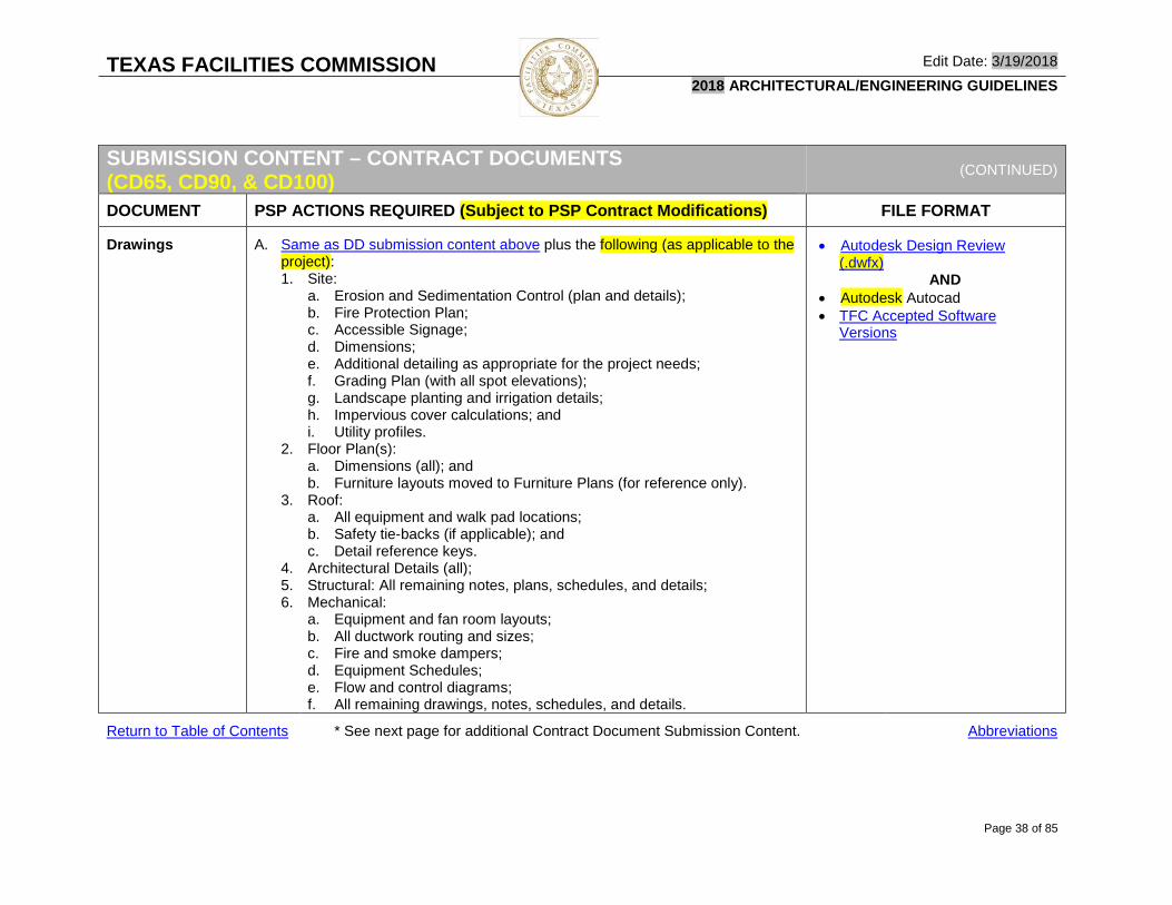
Drawings A. Same as DD submission content above plus the following (as applicable to the project): 1. Site:
a. Erosion and Sedimentation Control (plan and details); b. Fire Protection Plan; c. Accessible Signage; d. Dimensions; e. Additional detailing as appropriate for the project needs; f. Grading Plan (with all spot elevations); g. Landscape planting and irrigation details; h. Impervious cover calculations; and i. Utility profiles.
2. Floor Plan(s): a. Dimensions (all); and b. Furniture layouts moved to Furniture Plans (for reference only).
3. Roof: a. All equipment and walk pad locations; b. Safety tie-backs (if applicable); and c. Detail reference keys.
4. Architectural Details (all); 5. Structural: All remaining notes, plans, schedules, and details; 6. Mechanical:
a. Equipment and fan room layouts; b. All ductwork routing and sizes; c. Fire and smoke dampers; d. Equipment Schedules; e. Flow and control diagrams; f. All remaining drawings, notes, schedules, and details.
• Autodesk Design Review (.dwfx)
AND • Autodesk Autocad • TFC Accepted Software
Versions
Return to Table of Contents * See next page for additional Contract Document Submission Content. Abbreviations

TEXAS FACILITIES COMMISSION Edit Date: 3/19/2018 2018 ARCHITECTURAL/ENGINEERING GUIDELINES
Page 39 of 85
SUBMISSION CONTENT – CONTRACT DOCUMENTS (CD65, CD90, & CD100)
(CONTINUED)
DOCUMENT PSP ACTIONS REQUIRED (Subject to PSP Contract Modifications) FILE FORMAT
Drawings (Continued)
1. Electrical / Fire Alarm: a. Electrical details showing such things as:
i. Grounding; ii. ATS; iii. Wiring; iv. Lightning protection; v. Fencing; and vi. Housekeeping pads.
b. All remaining notes, plans, schedules, and details. 2. Plumbing / Fire Protection:
a. Equipment and pump room layouts; b. All piping routing and sizes; c. Fixture and Equipment Schedules; d. Flow and riser diagrams; e. Fire sprinkler hazard zones; f. Fire hydrant static and residual pressures:
i. Indicate fire and / or domestic water pump requirements. B. All remaining notes, plans, schedules, and details.
• Autodesk Design Review (.dwfx)
AND • Autodesk Autocad • TFC Accepted Software
Versions
Specifications A. Provide complete Project Manual: 1. Format: 3 part CSI MasterFormat 2004/2016. 2. Include all TFC Front-End documents as provided by TFC’s PM. 3. Include the following TFC-provided matrices at the end of the Project
Close Out section of the Project Manual and complete them to reflect project specific requirements: a. Submittals; b. Warranties; c. Testing; d. Training; and e. Manuals.
B. See the Appendices for relevant technical standards.
• Autodesk Design Review (.dwfx)
Return to Table of Contents * See next page for additional Contract Document Submission Content. Abbreviations

TEXAS FACILITIES COMMISSION Edit Date: 3/19/2018 2018 ARCHITECTURAL/ENGINEERING GUIDELINES
Page 40 of 85
SUBMISSION CONTENT – CONTRACT DOCUMENTS (CD65, CD90, & CD100)
(CONTINUED)
DOCUMENT PSP ACTIONS REQUIRED (Subject to PSP Contract Modifications) FILE FORMAT
Narratives / Analyses / Evaluations
A. Revise narratives and analyses submitted in the previous phase: 1. Summarize decisions made (and supporting reasons) for each.
B. Update the DD MEP systems narratives to indicate intended operational and maintenance procedures (for building occupants). 1. Address requirements of ASHRAE Standard 180 - Standard Practice for
Inspection and Maintenance of Commercial Building HVAC Systems. C. Estimate to what extent structural, building envelope, & hardscape materials
need to be replaced or repaired.
• Autodesk Design Review (.dwfx)
• TFC Accepted Software Versions
Data / Calculations
A. Same as DD submission content above and indicate the following: 1. Room by room electrical load analysis per ASHRAE 90.1 or IECC
(currently adopted edition); 2. Changes from previous submission; 3. Duct and piping calculations; 4. Air balance calculations; 5. Energy and ventilation calculations.
Return to Table of Contents Abbreviations

TEXAS FACILITIES COMMISSION Edit Date: 3/19/2018 2018 ARCHITECTURAL/ENGINEERING GUIDELINES
Page 41 of 85
Contract Bidding & Award
SUBMISSION CONTENT – CONTRACT BIDDING AND AWARD (BA)
DOCUMENT PSP ACTIONS REQUIRED (Subject to PSP Contract Modifications) FILE FORMAT
General A. Execute and issue bid documents that form the basis of competitive price proposals.
Executive Summary Report
A. Revise the previous report to reflect current project conditions. • Autodesk Design Review (.dwfx)
• TFC Accepted Software Versions
Schedule for Delivery of Services
A. Revise the previous Schedule to reflect any changes to anticipated task durations and milestone dates.
Space Allocation Program
A. Same as DD submission content above. • Autodesk Design Review (.dwfx)
Bid Documents A. Provide final, executed (sealed and signed): 1. Drawings and Specifications reflecting satisfactory responses to TFC
comments; and 2. Addenda and Clarifications as required to sufficiently respond to:
a. Requirements of regulatory authorities; b. Bidder Requests for Information; and c. Requests for Substitution.
• Autodesk Design Review (.dwfx)
AND • Autodesk Autocad • TFC Accepted Software
Versions
BIM Models A. Provide all BIM model and annotation files (and all linked files) reflecting the information contained within the Bid Documents as described below.
B. See BIM Standards for more information.
• Autodesk Navisworks (.nwd and .nwf files)
• Autodesk Civil3D • Autodesk Revit
Narratives / Analyses / Evaluations
A. Revise narratives and analyses submitted in the previous phase: 1. Summarize decisions made (and supporting reasons) for each.
Return to Table of Contents * See next page for additional Contract Bidding and Award Submission Content. Abbreviations

TEXAS FACILITIES COMMISSION Edit Date: 3/19/2018 2018 ARCHITECTURAL/ENGINEERING GUIDELINES
Page 42 of 85
SUBMISSION CONTENT – CONTRACT BIDDING AND AWARD (BA) (CONTINUED)
DOCUMENT PSP ACTIONS REQUIRED (Subject to PSP Contract Modifications) FILE FORMAT
Data / Calculations
A. Same as CD submission content above.
SECO Documentation
A. Submit sealed and executed SECO compliance forms and supporting documentation in accordance with SECO requirements and the Submission Procedures section of this document.
Accessibility Review
A. Register project and submit documentation to TDLR or a RAS in accordance with the TDLR requirements and the Submission Procedures section of this document.
Hazardous Materials Certification
A. Submit letter (complying with the hazardous materials statutory requirements listed above) certifying that the project and all parts of any building(s) affected by the project do not contain asbestos.
• Adobe PDF
TCEQ / EPA Documentation
A. Submit: 1. SWPPP complying with TAC Title 30, Part 1, Chapter 213, Subchapter B,
RULE §213.24. 2. SPCC Plan (EPA) for fuel storage tanks; 3. Fuel storage tank registration (TCEQ).
• As required by TCEQ and/or EPA
Return to Table of Contents Abbreviations

TEXAS FACILITIES COMMISSION Edit Date: 3/19/2018 2018 ARCHITECTURAL/ENGINEERING GUIDELINES
Page 43 of 85
Construction
SUBMISSION CONTENT – CONSTRUCTION (CA)
DOCUMENT PSP ACTIONS REQUIRED (Subject to PSP Contract Modifications) FILE FORMAT
Schedule for Delivery of Services
A. Revise the previous Schedule to reflect any changes to anticipated task durations and milestone dates.
• Autodesk Design Review (.dwfx)
Consolidated Contract Documents
A. Provide final, executed (sealed and signed) Drawings and Specifications updated to reflect all revisions including Addenda and Clarifications issued during the Contract Bidding and Award phase.
• Autodesk Design Review (.dwfx)
AND • Autodesk Autocad • TFC Accepted Software
Versions
BIM Model and Annotation Files
A. Provide all BIM model and annotation files (and all linked files) reflecting the information contained within the Consolidated Contract Documents as described above;
B. See BIM Standards for more information.
• Autodesk Navisworks (.nwd and .nwf files)
• Autodesk Civil3D • Autodesk Revit
Change Documentation
A. Provide final, executed (sealed and signed) Change Documentation including Drawings and Specifications reflecting agreed upon changes to the Contract for Construction such as: 1. Minor Changes / Supplemental Instructions (UGC 11.4) such as those
resulting from: a. Modifications to shop drawings and other submittals; b. RFI responses.
2. Changes resulting from unforeseen concealed conditions (UGC 11.5); and 3. Change Orders.
• Autodesk Design Review (.dwfx)
• TFC Accepted Software Versions
Return to Table of Contents Abbreviations

TEXAS FACILITIES COMMISSION Edit Date: 3/19/2018 2018 ARCHITECTURAL/ENGINEERING GUIDELINES
Page 44 of 85
Warranty
SUBMISSION CONTENT – CONSTRUCTION (CA)
DOCUMENT PSP ACTIONS REQUIRED (Subject to PSP Contract Modifications) FILE FORMAT
Record Documents
A. Update Drawings and specifications to reflect the “as-constructed” condition of the complete scope of the project as recorded in Contractor’s as-constructed field marked Record Documents and all: 1. Addenda; 2. Clarifications; 3. Minor Changes / Supplemental Instructions (UGC 11.4) such as those resulting from:
a. Modifications to shop drawings and other submittals; b. RFI responses.
4. Changes resulting from unforeseen concealed conditions (UGC 11.5); 5. Change Orders; and 6. Product, material, and equipment substitutions.
B. Finalize the MEP Systems Operations Manual. 1. Comply with ASHRAE Guideline 0, Informative Annex O.
• Autodesk Design Review • (.dwfx)
• AND • Autodesk Autocad • TFC Accepted Software
Versions • AND
• Microsoft Word 2007 • TFC Accepted Software
Versions
Record BIM Models
A. Update all BIM model and annotation files (and all linked files) to reflect the information contained within the Record Documents as described above.
B. Tag all components in the BIM models with embedded hyperlinks to the relevant: 1. Specification section in the Project Manual; 2. Product / Equipment Information in the O&M Manual; 3. Final, accepted Submittal Data; 4. Training Materials; 5. Commissioning Documentation; 6. Systems Manuals; and 7. Warranty Documents.
C. See BIM Standards for more information.
• Autodesk Navisworks (.nwd and .nwf files)
• Autodesk Civil3D • Autodesk Revit
Return to Table of Contents Abbreviations

TEXAS FACILITIES COMMISSION Edit Date: 3/19/2018 2018 ARCHITECTURAL/ENGINEERING GUIDELINES
Page 45 of 85
DRAWING STANDARDS - RECOMMENDED DOCUMENT ORGANIZATION
DRAWING STANDARDS – RECOMMENDED DOCUMENT ORGANIZATION
Purpose A. Facilitate familiarity of the document structure and contents by all parties.
B. Deviations from the recommended document organization standards (when appropriate) must receive prior written approval from TFC’s PM.
Drawing Numbering: A. Begin numbering in the bottom
right corner. B. Continue numbering upward
and then to the left.
Keyed Notes) TFC prohibits the use of the Con-Doc keyed notes system.
Detail Manuals: TFC prohibits the use of Detail Manuals. All details are to be included in the Drawings.
Door Hardware Schedule: Locate in drawings not Project Manual. SCHEDULES DIAGRAMS
General (Notes, Abbreviations, and
Symbols)Existing /
Demolition PlanEnlarged
PlanPlan
Detail ElevationEnlarged Elevation
Elevation Detail Section
Enlarged Section
Section Detail
Enlarged Section Detail
0 1 2 3 4 5 6 7 8 9 10 11 12 13
SECTIONSPLANS ELEVATIONSDESIGN DISCIPLINE
Cover G0-00Project Information G0-01Accessibility AR-01…Code Review CR-01…General NotesCivil C0-00 C1-100 C2-100 C3-100 C4-100 C8-100 C12-100 C13-100
Dimension Control C1-200 C2-200 C3-200 C4-200 C8-200 C12-200 C13-200Erosion / Sedimentation C1-300 C2-300 C3-300 C4-300 C8-300 C12-300 C13-300Grading C1-400 C2-400 C3-400 C4-400 C8-400 C12-400 C13-400Storm Water C1-500 C2-500 C3-500 C4-500 C8-500 C12-500 C13-500Utilities C1-600 C2-600 C3-600 C4-600 C8-600 C12-600 C13-600
Landscape L0-000 L1-100 L2-100 L3-100 L4-100 L5-100 L6-100 L7-100 L8-100 L9-100 L10-100 L11-100 L12-100Hardscape L1-200 L2-200 L3-200 L4-200 L5-200 L6-200 L7-200 L8-200 L9-200 L10-200 L11-200 L12-200 L13-200Planting L1-300 L2-300 L3-300 L4-300 L8-300 L9-300 L10-300 L11-300 L12-300 L13-300Irrigation L1-400 L2-400 L3-400 L4-400 L8-400 L9-400 L10-400 L11-400 L12-400 L13-400
Structural S0-000 S1-100 S2-100 S3-100 S4-100 S5-100 S6-100 S7-100 S8-100 S9-100 S10-100 S11-100 S12-100 S13-100Architecture A0-000 A1-100 A2-100 A3-100 A4-100 A5-100 A6-100 A7-100 A8-100 A9-100 A10-100 A11-100 A12-100
Site A1-200 A2-200 A3-200 A4-200 A5-200 A6-200 A7-200 A8-200 A9-200 A10-200 A11-200 A12-200Floor / Roof A1-300 A2-300 A3-300 A4-300 A5-300 A6-300 A7-300 A8-300 A9-300 A10-300 A11-300 A12-300Openings A12-400Ceiling A1-500 A2-500 A3-500 A4-500 A5-500 A6-500 A7-500 A8-500 A9-500 A10-500 A11-500 A12-500Wall A1-600 A2-600 A3-600 A4-600 A5-600 A6-600 A7-600 A8-600 A9-600 A10-600 A11-600 A12-600
Return to Table of Contents * See next page for additional Recommended Document Organization Standards. Abbreviations
2
3
5
6
8
9
1 4 7

TEXAS FACILITIES COMMISSION Edit Date: 3/19/2018 2018 ARCHITECTURAL/ENGINEERING GUIDELINES
Page 46 of 85
DRAWING STANDARDS – RECOMMENDED DOCUMENT ORGANIZATION (CONTINUED)
SCHEDULES DIAGRAMSGeneral (Notes,
Abbreviations, and Symbols)
Existing / Demolition Plan
Enlarged Plan
Plan Detail Elevation
Enlarged Elevation
Elevation Detail Section
Enlarged Section
Section Detail
Enlarged Section Detail
0 1 2 3 4 5 6 7 8 9 10 11 12 13
SECTIONSPLANS ELEVATIONSDESIGN DISCIPLINE
Interior I0-000 I1-100 I2-100 I3-100 I4-100 I5-100 I6-100 I7-100 I8-100 I9-100 I10-100 I11-100 I12-100
Floor I1-200 I2-200 I3-200 I4-200 I5-200 I6-200 I7-200 I8-200 I9-200 I10-200 I11-200 I12-200Ceiling I1-300 I2-300 I3-300 I4-300 I5-300 I6-300 I7-300 I8-300 I9-300 I10-300 I11-300 I12-300Wall I1-400 I2-400 I3-400 I4-400 I5-400 I6-400 I7-400 I8-400 I9-400 I10-400 I11-400 I12-400Casework I1-500 I2-500 I3-500 I4-500 I5-500 I6-500 I7-500 I8-500 I9-500 I10-500 I11-500 I12-500Finishes I1-600 I2-600 I3-600 I12-600Furniture I1-700 I2-700 I3-700 I4-700 I5-700 I6-700 I7-700 I8-700 I9-700 I10-700 I11-700 I12-700Signage I1-800 I2-800 I3-800 I4-800 I5-800 I6-800 I7-800 I8-800 I9-800 I10-800 I11-800 I12-800
Mechanical M0-000 M1-100 M2-100 M3-100 M4-100 M8-100 M12-100 M13-100Piping M1-200 M2-200 M3-200 M4-200 M8-200 M12-200 M13-200
Building Automation & Contro BA-000 BA1-100 BA2-100 BA3-100 BA4-100 BA8-100 BA12-100 BA13-100Electrical E0-000 E1-100 E2-100 E3-100 E4-100 E8-100 E12-100 E13-100
Power E1-200 E2-200 E3-200 E4-200 E8-200 E12-200 E13-200Lighting E1-300 E2-300 E3-300 E4-300 E8-300 E12-300 E13-300Fire Alarm E1-400 E2-400 E3-400 E4-400 E8-400 E12-400 E13-400Mechanical E1-500 E2-500 E3-500 E4-500 E8-500 E12-500 E13-500
Tele/Data TD0-000 TD1-100 TD2-100 TD3-100 TD4-100 TD8-100 TD9-100 TD10-100 TD11-100 TD12-100 TD13-100Security SC-000 SC1-100 SC2-100 SC3-100 SC4-100 SC5-100 SC8-100 SC12-100 SC13-100Plumbing P0-000 P1-100 P2-100 P3-100 P4-100 P8-100 P12-100 P13-100Fire Protection FP0-000 FP1-100 FP2-100 FP3-100 FP4-100 FP8-100 FP12-100 FP13-100Food Service FS0-000 FS1-100 FS2-100 FS3-100 FS4-100 FS5-100 FS6-100 FS7-100 FS8-100 FS9-100 FS10-100 FS11-100 FS12-100 FS13-100Other ??0-000 ??1-100 ??2-100 ??3-100 ??4-100 ??5-100 ??6-100 ??7-100 ??8-100 ??9-100 ??10-100 ??11-100 ??12-100 ??13-100 Partition Types A. See Partition Types information in BIM Standards. • TFC Partition Types
Door Types A. See Door Types information in BIM Standards. • TFC Door Types
Room Styles A. See Revit Room Styles information in BIM Standards. • TFC Room Styles
Materials Designations
A. See Revit Materials information in BIM Standards. • TFC Materials
Return to Table of Contents Abbreviations

TEXAS FACILITIES COMMISSION Edit Date: 3/19/2018 2018 ARCHITECTURAL/ENGINEERING GUIDELINES
Page 47 of 85
BIM / CADD STANDARDS - OVERVIEW
BIM / CADD STANDARDS – OVERVIEW
LINKS
General A. TFC has adopted Building Information Modeling (BIM) as a standard for all projects developed under TFC authority involving new construction and additions.
B. For deferred maintenance and minor alteration projects, Building Information Modeling (BIM) is preferred but not necessarily required. 1. CADD software may be used only with prior written authorization from TFC’s
PM and TFC’s IAECS Director.
• BIM Standards • CADD Standards • TFC Accepted Software
Versions
Purpose A. Facilitate implementation of TFC standards; B. Minimize document review turn-around time through standardization of:
1. Elements common to all TFC projects: 2. Format and organization of documents.
C. Streamline TFC facilities management and maintenance processes from the date of occupancy through the life of the property.
Software Requirements
A. All BIM Model files and CADD files are required to be created using BIM or CADD authoring software in native file formats readable by the current software versions in use by TFC as indicated below: 1. Autodesk Autocad – All versions through 2017 2. Autodesk Civil 3D - All versions through 2017 3. Autodesk Navisworks- 2017 4. Autodesk Revit - 2017 5. Autodesk Collaboration for Revit (C4R) - 2017
B. PSPs are responsible for providing proper software training for their staff members assigned to TFC projects.
• Autodesk Autocad • Autodesk Civil 3D • Autodesk Navisworks • Autodesk Revit • Autodesk Collaboration for Revit
BIM Team Collaboration
A. TFC will provide a cloud-based team collaboration environment for all project related BIM files as defined later in this document.
B. PSPs will develop BIM files in TFC’s collaboration environment in accordance with TFC’s BIM standards.
• BIM Standards • BIM Standards – File Types
Return to Table of Contents Abbreviations

TEXAS FACILITIES COMMISSION Edit Date: 3/19/2018 2018 ARCHITECTURAL/ENGINEERING GUIDELINES
Page 48 of 85
CADD STANDARDS
CADD STANDARDS
STANDARD DESCRIPTION LINKS
Purpose A. Provide a uniform format for CADD based projects developed under TFC authority.
Template Files A. The following standard files will be provided by TFC: 1. Cover Sheet; 2. Blank titleblock; 3. Partition Types and Details; and 4. Door Types Legend.
• TFC ACAD Template Files • TFC Partition Types • TFC Door Types
Existing Conditions Files
A. In cases of facility renovation projects, a copy of the existing CADD drawing files and associated Record Documentation will be made available for download through the project’s IMPACT folder structure.
B. These files and documents shall be utilized in the preparation of all related design and contract documents.
Accuracy A. All CAD drawings shall be drafted using precision input employing the most accurate source material available.
B. For all drawing entities, zero tolerance is required: 1. All lines meet at intersections; 2. Straight lines are straight; 3. Blocks are inserted properly without overlap; 4. Closure of all polygons, etc.
Return to Table of Contents * See next page for additional CADD Standards. Abbreviations

TEXAS FACILITIES COMMISSION Edit Date: 3/19/2018 2018 ARCHITECTURAL/ENGINEERING GUIDELINES
Page 49 of 85
CADD STANDARDS (CONTINUED)
STANDARD DESCRIPTION LINKS
Color A. Color will be used to control pen assignments and line weights. B. Select layer colors in accordance with the “Pen / Color Values Table”. C. Create all objects with color bylayer.
Linetypes A. Use only standard linetypes. B. Contour lines, dashed lines and other fonted lines shall be made of one
continuous line segment, not a series of separate line segments. C. A sample drawing must be submitted and approved by the CAD Manager if
multilines are used.
Units A. Set DDUNITS to architectural and angles to deg/min/sec with the precision set at 1/16"
Blocks A. Any graphic entity that occurs repeatedly in drawings should be made into a block.
B. Insertion points for blocks shall be consistent with its placement in the drawing 1. Keep names simple and descriptive. 2. Use a logical insertion point (center of circle, bottom left corner of object). 3. Blocks must be drawn on layer 0 and inserted on the proper layer; or drawn
on the proper layer/ layers and inserted on layer 0. C. Nested blocks are permitted but should be avoided whenever possible. D. If custom nested blocks are used, TFC’s CADD Manager must approve them.
External Reference Files (XRefs)
A. Bind (do not insert) all reference files into the active file.
Scale A. All model space files must be drawn at real size (1-to-1). B. Objects must be created at full size:
1. A 50-foot wall must be drawn to 50 feet 0”; and 2. A 48-inch column must be drawn to 48 inches.
C. CAD files will be drawn in 2D only (not 3D).
Return to Table of Contents * See next page for additional CADD Standards. Abbreviations

TEXAS FACILITIES COMMISSION Edit Date: 3/19/2018 2018 ARCHITECTURAL/ENGINEERING GUIDELINES
Page 50 of 85
CADD STANDARDS (CONTINUED)
STANDARD DESCRIPTION LINKS
Text and Fonts A. Use only standard text fonts supplied with AutoCAD’s font library. B. Fonts for lettering shall be readable and plottable by AutoCAD with no additional
software required. C. Text size must be legible and appropriate to the graphic information presented
and the intended plotted scale of the drawing.
Drawing Origin A. The lower left corner of the building shall be placed at 0,0,0. B. For non-rectilinear buildings a logical origin point shall be established. C. The origin point must remain consistent between all model files for the purpose
of xref coordination. D. Once the origin is established, it may not be changed.
Dimensions A. All dimensioning shall be associative. 1. Break lines and parts of cut-through views are an exception.
B. Preferred dimension styles are provided in the template file.
Hatching A. Use pattern hatching sparingly since the practice significantly increases the AutoCAD entity count of a drawing.
B. Associative hatching may be used only with the approval of TFC’s CAD Manager.
C. Use the solid command or polyline command to represent solid-filled regions when possible.
Layers A. CADD drawings shall be organized in accordance with the TFC Layering Guidelines. 1. If the TFC format does not include an appropriate layer name, layer names
shall be in accordance with CAD Layer Guidelines as published by the American Institute of Architects (A.I.A.).
B. The layer names shall be the long format and shall include the modifier. C. As these layer guidelines allow flexibility in the assignment of layers, a Layer
Matrix shall be provided to TFC with the Record Documents. D. All third party add on application packages which modify or create CAD layers or
other entities must comply with the AIA CAD Layer Guidelines.
Return to Table of Contents * See next page for additional CADD Standards. Abbreviations

TEXAS FACILITIES COMMISSION Edit Date: 3/19/2018 2018 ARCHITECTURAL/ENGINEERING GUIDELINES
Page 51 of 85
CADD STANDARDS (CONTINUED)
STANDARD DESCRIPTION LINKS
Area Calculations
A. Include the following area calculations using area polylines included in the “as-built” submittal. 1. Construction Area – Area calculation boundary line will be drawn around the
exterior Floor Plan for each level of building on layer a-area-cons 2. Gross Area - Area calculation boundary line will be drawn around interior
Floor Plan for each level of building on layer a-area-gros 3. Room Area - Area calculation boundary line will be drawn around each room
from the centerline of the wall on layer a-area-room B. Wall edges, partition centerlines and structural centerlines used for area
polygons, should be saved in the layers listed above, as appropriate.
Quality Check A. Check the CADD files to verify the following: 1. All entities are:
a. Dimensionally accurate; b. Inserted on the proper layer;
2. Column and grid line dimensions are correct; 3. Entity intersections meet each other properly; 4. Entities outside the drawing limits are deleted. 5. Colors and linetypes are assigned BYLAYER; 6. Layering system conforms to TFC and AIA CAD Layer Standard.
B. Correct any non-compliant conditions. C. Confirm that all files are free of viruses.
Purge / Audit A. If the drawing file becomes too large, response to commands will be slow and regeneration times will be longer.
B. Prior to submitting files: 1. Purge all unused blocks, linetypes and layers. 2. Audit all files and “Fix All Errors”.
Return to Table of Contents Abbreviations

TEXAS FACILITIES COMMISSION Edit Date: 3/19/2018 2018 ARCHITECTURAL/ENGINEERING GUIDELINES
Page 52 of 85
BIM STANDARDS BIM Standards - File Types
BIM STANDARDS – FILE TYPES
FILE TYPE DEFINITION LINKS
Purpose A. Facilitate the effective and efficient implementation of BIM in the design and documentation of projects within TFC’s jurisdictional authority.
B. Allow for dynamic, simultaneous modifications of multiple portions of any given facility (by both internal and external service providers).
C. Maintain an accurate, current, easily accessible record of the existing condition of all facilities even while proposed design and/or construction modifications are underway.
General A. There are two types of files for a TFC project: 1. Model Files contain all physical features of the project;
a. Existing conditions to remain; i. The extent of existing conditions modeling required beyond the
affected areas and the level of information to be included will be determined based on project-specific needs.
b. Existing conditions to be removed; c. Proposed new construction; and d. All elements tagged with CSI Uniformat Level 4 categories. e. Annotations such as working dimensions, tags, and other annotation
elements utilized for purposes other than formal documentation may be incorporated in the model files but must be purged prior to submitting final deliverable to TFC.
2. Annotation Files contain all non-physical formal documentation information (such as title blocks, notes, dimensions, details, schedules, etc.) describing the physical features contained in the model files.
3. All drawings and schedules required for assessment, review, bidding and construction shall be extractions from the model file(s).
B. Separating the project into model and annotation files is intended to: 1. Limit the size of the “Central File”; 2. Maximize workflow efficiency; and 3. Protect discipline specific work from unauthorized modification.
• BIM Standards (Workflow Diagram)
Return to Table of Contents * See next page for additional BIM Workflow Diagram. Abbreviations

TEXAS FACILITIES COMMISSION Edit Date: 3/19/2018 2018 ARCHITECTURAL/ENGINEERING GUIDELINES
Page 53 of 85
BIM Standards – Work Flow Diagram
BIM STANDARDS – WORKFLOW DIAGRAM
Return to Table of Contents * See next page for additional BIM File Types. Abbreviations

TEXAS FACILITIES COMMISSION Edit Date: 3/19/2018 2018 ARCHITECTURAL/ENGINEERING GUIDELINES
Page 54 of 85
BIM STANDARDS – FILE TYPES (CONTINUED)
FILE TYPE DEFINITION LINKS
Model Types A. Each TFC facility has (or will have) a Federated system of Models linked together to create a unified whole:
B. Master Models: Contain no native model elements, but are a conglomeration of Linked Component Models: 1. The various types of Master Models are:
a. Campus Master Model; b. Site Master Models; and; c. Building Master Model.
C. Component Models are discrete subsets of the larger facility containing native elements (from all disciplines) representing all physical features within the Component Model’s clearly defined scope boundaries. 1. Each is linked into the Master Model and other relevant Component Models
with “Origin to Origin” positioning. 2. No model objects are duplicated between the various Component Models. 3. The various types of Component Models are:
a. Site Component Models; and b. Building Component Models
D. Each Model has (or will have) multiple copies: 1. Current Conditions Models:
a. Reflect the actual, current state of the facility; b. Are linked into the relevant Master Model; and c. Are located on TFC’s local area network..
2. Project Copy Models: a. Reflect proposed modifications for each unique and on-going project b. Are NOT linked into the Master Models. c. Are copied from the relevant Current Conditions Models at the beginning
of any given project; d. Are hosted in TFC’s cloud-based collaboration environment and
provided to PSP by invitation from TFC.
Return to Table of Contents * See next page for additional BIM File Types. Abbreviations

TEXAS FACILITIES COMMISSION Edit Date: 3/19/2018 2018 ARCHITECTURAL/ENGINEERING GUIDELINES
Page 55 of 85
BIM STANDARDS – FILE TYPES (CONTINUED)
FILE TYPE DEFINITION LINKS
Model Types (Continued)
3. Archive Copy Models are saved as a record of previous conditions. After Record Document changes are recorded in the Project Copy Models:
a. Each Current Conditions Model is copied to the appropriate archive folder on TFC’s network; and
b. Each recently completed Record Model will be copied back into the Current folder on TFC’s network and replaces its respective Current Conditions Model.
Campus Master Models
A. Contain linked Building Component Model(s) and Site Component Model(s). B. File naming convention:
1. Current Conditions Model: (Facility Abbreviation)_MODEL_CAMPUS_YYYY (Revit Version)
2. Proposed Modifications Models: (Facility Abbreviation) _( PRJ #)_MODEL_CAMPUS_YYYY (Revit Version)
Site Component Models
A. Contain all physical and regulatory features of portions of the facility’s site: 1. Property Lines; 2. Easements and setbacks; 3. Topography; 4. Roadways; 5. Parking; 6. Walkways; 7. Site Utilities (terminate 5 feet from building face); 8. Walls and Fences; 9. Site Furnishings; 10. Landscape Planting; 11. Drainage Structures;
B. File naming convention: 1. Current Conditions Model:
(Facility Abbreviation)_MODEL_SITE_YYYY (Revit Version) 2. Proposed Modifications Models:
(Facility Abbreviation) _( PRJ #)_MODEL_SITE_YYYY (Revit Version)
Return to Table of Contents * See next page for additional BIM File Types. Abbreviations

TEXAS FACILITIES COMMISSION Edit Date: 3/19/2018 2018 ARCHITECTURAL/ENGINEERING GUIDELINES
Page 56 of 85
BIM STANDARDS – FILE TYPES (CONTINUED)
FILE TYPE DEFINITION LINKS
Building Master Models
A. Contain linked Building Component Models. B. File naming convention:
1. Current Conditions Model: (Building Abbreviation)_MODEL_MASTER_YYYY (Revit Version)
2. Proposed Modifications Models: Not Applicable
Building Component Models
A. Contain all physical features of the relevant Building Components as defined later in this document.
B. There are 4 types of Building Component Models: 1. Structural Model (one per building); 2. Building Shell Model (one per building); 3. Core Model (one per floor); and 4. Suite (Tenant Space) Model (one per suite).
C. Shade Structures and pavilions are to be treated as independent buildings.
Structural Component Models
A. Contain All physical features of the building structure (one file per building): 1. Structural Grid; 2. Foundations; 3. Structural Floors; 4. Structural Walls; and 5. Structural Framing.
B. File naming convention: 1. Current Conditions Model:
(Facility Abbreviation)_MODEL_STRUCT_YYYY (Revit Version) 2. Proposed Modifications Models:
(Facility Abbreviation)_( PRJ #)_MODEL_STRUCT_YYYY (Revit Version)
Return to Table of Contents * See next page for additional BIM File Types. Abbreviations

TEXAS FACILITIES COMMISSION Edit Date: 3/19/2018 2018 ARCHITECTURAL/ENGINEERING GUIDELINES
Page 57 of 85
BIM STANDARDS – FILE TYPES (CONTINUED)
FILE TYPE DEFINITION LINKS
Building Shell Component Models
A. Contain all Architectural and MEP features of the exterior building envelope and vertical building systems/components (one file per building): 1. Exterior Walls; 2. Exterior Openings; 3. Awnings and canopies; 4. Roof Systems; 5. Vertical Circulation Elements (including shaft walls, openings, and opening
protective devices); 6. Building-wide MEP equipment and distribution systems (including shaft
walls, openings, and opening protective devices) - Terminate Mechanical, Electrical, and Plumbing systems using a “System Surrogate” Family to simulate the continuation of the relevant system in the adjoining Component Model(s): a. At the outside face of vertical shaft enclosures; and b. At the tenant side of the common corridor partition.
B. File naming convention: 1. Current Conditions Model:
(Facility Abbreviation)_MODEL_SHELL_YYYY (Revit Version) 2. Proposed Modifications Models:
(Facility Abbreviation)_(PRJ #)_MODEL_SHELL_YYYY (Revit Version)
Return to Table of Contents * See next page for additional BIM File Types. Abbreviations

TEXAS FACILITIES COMMISSION Edit Date: 3/19/2018 2018 ARCHITECTURAL/ENGINEERING GUIDELINES
Page 58 of 85
BIM STANDARDS – FILE TYPES (CONTINUED)
FILE TYPE DEFINITION LINKS
Core Component Models
A. Contain all features of the Building Common Areas including Architectural, MEP, and Life Safety systems (one file per floor including the roof/penthouse): 1. Entrance Lobby; 2. Restrooms; 3. Corridors; 4. Tenant Space Demising Partitions and Openings; 5. Equipment Rooms; 6. Floor-wide MEP equipment and distribution systems - Terminate
Mechanical, Electrical, and Plumbing systems using a “System Surrogate” Family to simulate the continuation of the relevant system in the adjoining Component Model(s): a. At the outside face of vertical shaft enclosures; and b. At the tenant side of the common corridor partition.
B. File naming convention: 1. Current Conditions Model:
(Facility Abbreviation)_MODEL_CORE_L# (Floor Level) _YYYY (Revit Version)
2. Proposed Modifications Models: (Facility Abbreviation)_(PRJ #)_MODEL_CORE_L# (Floor Level)
Return to Table of Contents * See next page for additional BIM File Types. Abbreviations

TEXAS FACILITIES COMMISSION Edit Date: 3/19/2018 2018 ARCHITECTURAL/ENGINEERING GUIDELINES
Page 59 of 85
BIM STANDARDS – FILE TYPES (CONTINUED)
FILE TYPE DEFINITION LINKS
Suite Component Models (Tenant Spaces)
A. Contain all features of individual Tenant Suites within the boundaries of its demising partitions including Architectural, MEP, and Life Safety systems (one file per tenant space): 1. Programmed spaces (tenant lobbies, restrooms, copy/print rooms, offices,
storage rooms, etc.); 2. Furniture, Fixtures and Equipment (FF&E); 3. Vertical circulation serving only an individual tenant space; 4. MEP Systems - Terminate Mechanical, Electrical, and Plumbing systems
using a “System Surrogate” Family to simulate the continuation of the relevant system in the adjoining Component Model(s): a. At the outside face of vertical shaft enclosures; b. At the tenant side of the common corridor partition; and c. At the centerlines of demising partitions between Suites.
B. File naming convention: 1. Current Conditions Model:
(Facility Abbreviation)_MODEL_SUITE_(Suite Number) _YYYY (Revit Version)
2. Proposed Modifications Models: (Facility Abbreviation) _(PRJ #)_MODEL_ SUITE_ (Suite Number) _YYYY (Revit Version)
Return to Table of Contents * See next page for additional BIM File Types. Abbreviations

TEXAS FACILITIES COMMISSION Edit Date: 3/19/2018 2018 ARCHITECTURAL/ENGINEERING GUIDELINES
Page 60 of 85
BIM STANDARDS – FILE TYPES (CONTINUED)
FILE TYPE DEFINITION LINKS
Project Annotation Files
A. Contain all project-specific, non-physical information (such as notes, dimensions, etc.) describing the physical features contained in the Model Files.
B. All relevant Model Files are linked in to each Project Annotation File with “Origin to Origin” positioning.
C. Explanatory Comments: 1. Revit has several limiting factors that hinder the development of annotative
information for multiple projects within a single file: a. Duplicate Sheet Numbers are not allowed; and b. Parametric titleblocks are populated by the data entered in the “Manage
/ Project Information” dialog box that does not accommodate input for more than one project per Revit file.
2. There are two possibilities for dealing with these limitations: a. Create a new Model File containing both model and annotation objects
for each project. Duplicating a facility’s Model File for each project is not desired because it would result in: (a) A large collection of uncoordinated redundant Model Files; and (b) Version control issues with no one Model File containing the latest
information for the overall facility. b. Create a separate Annotation file for each project. Separating the
annotative information from the Model File and creating a unique Annotation File for each project is recommended since it: (a) Works within Revit’s limited capabilities to allow unique “Project
Information” to be associated with each Project; and (b) Allows a single Model File to be linked into multiple Annotation Files
thereby: (i) Eliminating redundant, uncoordinated Model information; and (ii) Providing access to the same, current Model information for all
projects within the facility.
Return to Table of Contents * See next page for additional BIM File Types. Abbreviations

TEXAS FACILITIES COMMISSION Edit Date: 3/19/2018 2018 ARCHITECTURAL/ENGINEERING GUIDELINES
Page 61 of 85
BIM STANDARDS – FILE TYPES (CONTINUED)
FILE TYPE DEFINITION LINKS
Existing Conditions Model(s)
A. In cases of facility renovation projects, a copy of any existing BIM file(s) and associated Record Documentation will be made available to PSP via TFC’s cloud-based team collaboration environment.
B. The existing conditions model file(s) and documentation shall be utilized in the preparation of all related design and contract documents.
Templates A. The following standard files will be provided to PSP by TFC: 1. Revit Model File with standardized information such as:
a. Project Phasing (and associated graphic overrides); b. Graphic conventions; c. Wall (Partition) types; d. Door types; e. Door hardware functions; f. Room finish types.
2. Revit Annotation File(s) with standardized information such as: a. Drawing sheet organization; b. Graphic conventions; c. Partition keys and details; d. Legends; e. Schedules.
3. Revit Titleblocks: a. Cover Sheet; and b. Other standard sheets.
B. These template files are provided for the convenience of design professionals providing services to TFC for projects developed under TFC authority.
C. The template files are intended to facilitate compliance with TFC design standards and must not replace the informed professional judgment of the PSP.
D. It is solely the PSP’s responsibility to determine the proper application of the standardized information contained within these files.
• TFC Revit 2013 Template Files • Model File • Annotation Files (11x17) • Annotation Files (24x36) • Annotation Files (30x42)
• TFC Revit 2015 Template Files • Model File • Annotation Files (11x17) • Annotation Files (24x36) • Annotation Files (30x42)
• TFC Revit 2017 Template Files • Model File • Annotation Files (11x17) • Annotation Files (24x36) • Annotation Files (30x42)
Return to Table of Contents Abbreviations

TEXAS FACILITIES COMMISSION Edit Date: 3/19/2018 2018 ARCHITECTURAL/ENGINEERING GUIDELINES
Page 62 of 85
BIM Standards – Team Collaboration
BIM STANDARDS – TEAM COLLABORATION
FILE TYPE DEFINITION LINKS
Revit Worksets A. TFC does not utilize Worksets. B. If utilized by PSP, remove worksets from final deliverable.
Collaboration for Revit (Cloud- Based Collaboration)
A. TFC has adopted a team collaboration process utilizing Autodesk’s “Collaboration for Revit (C4R)”. While not mandatory, TFC strongly recommends and urges all PSPs to utilize this process as it is the most efficient and effective means of delivering the final BIM model(s) in the format required by TFC. 1. All project Model Files as defined above are located within a TFC managed /
Autodesk hosted “BIM 360 Team Hub” cloud environment. a. TFC will act as the Administrator to provide access and permissions to
the various project team members. 2. Local Copies of the Central Files are downloaded and cached on individual
hard drives within each PSP’s office via C4R. 3. PSPs are responsible for obtaining and maintaining C4R licensing for each
Revit user within their respective offices.
• Autodesk Collaboration for Revit
• BIM Standards (Workflow Diagram)
Revit Software Build
A. TFC will provide information regarding the Revit Software Build (Release Version, Build number, and Update Release).
B. Primary PSP must insure that all project team members are using the same Revit Software Build (Release Version, Build number, and Update Release).
Return to Table of Contents Abbreviations

TEXAS FACILITIES COMMISSION Edit Date: 3/19/2018 2018 ARCHITECTURAL/ENGINEERING GUIDELINES
Page 63 of 85
Revit View Settings
BIM STANDARDS – REVIT VIEW SETTINGS
VIEW SCALE DETAIL LEVEL
MODEL GRAPHICS STYLE SHADOWS CROP
REGION PHASE PHASE FILTER
EXISTING Site Plans 1” = 20’-0” Coarse Hidden Line Off Off Existing Show All
Floor Plans 1/8” = 1’-0” Medium Hidden Line Off Off Existing Show All
Reflected Ceilings 1/8” = 1’-0” Medium Hidden Line Off Off Existing Show All
Exterior Elevations 1/8” = 1’-0” Coarse Hidden Line Off Off Existing Show All
Interior Elevations 3/8” = 1’-0” Medium Hidden Line Off Off Existing Show All
Building Sections 1/8” = 1’-0” Medium Hidden Line Off Off Existing Show All
Wall Sections ¾” = 1’-0” Fine Hidden Line Off Off Existing Show All
DEMOLITION Site Plans 1” = 20’-0” Coarse Hidden Line Off Off Demolition Show Previous + Demo
Floor Plans 1/8” = 1’-0” Medium Hidden Line Off Off Demolition Show Previous + Demo
Reflected Ceilings 1/8” = 1’-0” Medium Hidden Line Off Off Demolition Show Previous + Demo
Exterior Elevations 1/8” = 1’-0” Coarse Hidden Line Off Off Demolition Show Previous + Demo
Interior Elevations 3/8” = 1’-0” Medium Hidden Line Off Off Demolition Show Previous + Demo
Building Sections 1/8” = 1’-0” Medium Hidden Line Off Off Demolition Show Previous + Demo
Wall Sections ¾” = 1’-0” Fine Hidden Line Off Off Demolition Show Previous + Demo
Return to Table of Contents * See next page for additional Revit Architecture View Settings Standards. Abbreviations

TEXAS FACILITIES COMMISSION Edit Date: 3/19/2018 2018 ARCHITECTURAL/ENGINEERING GUIDELINES
Page 64 of 85
BIM STANDARDS – REVIT VIEW SETTINGS (CONTINUED)
VIEW SCALE DETAIL LEVEL
MODEL GRAPHICS STYLE SHADOWS CROP
REGION PHASE PHASE FILTER
NEW CONSTRUCTION Site Plans 1” = 20’-0” Coarse Hidden Line Off Off New Construction Show Previous + New
Floor Plans 1/8” = 1’-0” Medium Hidden Line Off Off New Construction Show Previous + New
Reflected Ceilings 1/8” = 1’-0” Medium Hidden Line Off Off New Construction Show Previous + New
Exterior Elevations 1/8” = 1’-0” Coarse Hidden Line Off Off New Construction Show Previous + New
Interior Elevations 3/8” = 1’-0” Medium Hidden Line Off Off New Construction Show Previous + New
Building Sections 1/8” = 1’-0” Medium Hidden Line Off Off New Construction Show Previous + New
Wall Sections ¾” = 1’-0” Fine Hidden Line Off Off New Construction Show Previous + New
Return to Table of Contents Abbreviations

TEXAS FACILITIES COMMISSION Edit Date: 3/19/2018 2018 ARCHITECTURAL/ENGINEERING GUIDELINES
Page 65 of 85
Revit Partitions
BIM STANDARDS – REVIT PARTITIONS
ELEMENT DEFINITION LINKS
Wall (Partition) Type Tags
A. When a “Wall Type” tag is placed, the correct partition type information is automatically populated.
Partition Assembly Type (Letter) Core Type (Digit) Partition Height Type (Letter - or - 2 Digits for Inches @ partial height walls)
Fire Rating (F+2 Digits) Sound Rating (S+2 Digit STC Rating)
B. Partition Assembly Type Codes: A = Metal stud framing with one layer of gypsum board on each side. B = Metal stud framing with two layers of gypsum board on each side. C = Metal stud furring partition with one layer of gypsum board on the
finished side. D = Metal stud Shaftwall with one inch shaft-liner and varying layers of
gypsum board on the finished face. E = Metal stud framing with resilient furring channels on one side and one
layer of gypsum board on each finished face. F = Metal stud framing with resilient furring channels on one side and two
layers of gypsum board on each finished face. G = Metal stud framed plumbing chase with 1 layer of gypsum board on
each finished face. H = Partial height metal stud framing with one layer of gypsum board on
each side. J = Fire rated metal stud partition with window(s) and deluge sprinklers. K = Concrete masonry units of varying widths.
Return to Table of Contents * See next page for additional Revit Architecture Partition Standards. Abbreviations

TEXAS FACILITIES COMMISSION Edit Date: 3/19/2018 2018 ARCHITECTURAL/ENGINEERING GUIDELINES
Page 66 of 85
BIM STANDARDS – REVIT PARTITIONS (CONTINUED)
ELEMENT DEFINITION LINKS
Wall (Partition) Type Tags (Continued)
A. Core Width Codes: 1 = 1 5/8" Metal Studs 3 = 3 5/8" Metal Studs 4 = 4" Metal Studs – or - 4" Nominal Masonry 6 = 6" Metal Studs – or - 6" Nominal Masonry 7 = 7” Clear inside width at metal stud framed plumbing chase 8 = 8" Metal Studs – or - 8" Nominal Masonry 9 = 9” Clear inside width at metal stud framed plumbing chase 12 = 12” Nominal Masonry
B. Partition Height Codes: A = Above Ceiling (to 6” above ceiling)
(Set the “Top Offset” constraint of the “Wall” to six inches more than the height of the ceiling in question)
C = Ceiling (to bottom of ceiling) (Attach the “Wall” to the “Ceiling”)
D = Deck High (to bottom of structural deck above) (Attach the “Wall” to the “Structural Floor or Roof” above)
## = Fixed Height (in inches to top of finish) (Set the “Unconnected Height” constraint of the “Wall” to the desired height of the partition at the top of the finished wall cap)
C. Sound Rating Codes: S## (## = 2 digit STC rating number)
D. Fire Rating Codes: F01 = 1 hour F02 = 2 hour F03 = 3 hour F04 = 4 hour F20 = 20 minutes F30 = 30 minutes F45 = 45 minutes F90 = 90 minutes
Return to Table of Contents * See next page for additional Revit Architecture Partition Standards. Abbreviations

TEXAS FACILITIES COMMISSION Edit Date: 3/19/2018 2018 ARCHITECTURAL/ENGINEERING GUIDELINES
Page 67 of 85
BIM STANDARDS – REVIT PARTITIONS (CONTINUED)
ELEMENT DEFINITION LINKS
Wall (Partition) Type Tags (Continued)
E. When the “Wall Type” is changed, the tag automatically updates with the appropriate information for the new partition type.
F. Custom “Wall Types” can be generated if necessary, but must include the following parametric “Identity Data” information: 1. Assembly Code - Edit Uniformat selection to match the wall construction ; 2. Type Mark – Assign a new partition type (use TFC naming conventions); 3. Fire Rating – Indicate if applicable. 4. Fire Test # - Provide UL assembly number if partition is fire rated; 5. Sound Test # - Provide STC rating if applicable; and 6. UL URL – Provide web address for specific UL assembly.
Wall (Partition) Types)
A. The Project Template file has a large library of TFC standard “Wall Types” (interior partitions) pre-loaded.
B. All TFC standard “Wall Types” contain parameter text that matches the appropriate TFC standard partition type.
C. “Wall Type” names are based on the Type Tag conventions above: 1. Example: “A3DS-51”
a. Partition Type: A b. Core Width: 3 5/8” metal stud framing c. Partition Height: Deck high d. Sound Rating: STC 51 e. Fire Rating: None
Return to Table of Contents Abbreviations

TEXAS FACILITIES COMMISSION Edit Date: 3/19/2018 2018 ARCHITECTURAL/ENGINEERING GUIDELINES
Page 68 of 85
Revit Door Types
BIM STANDARDS – REVIT DOOR TYPES (KEY SCHEDULE)
The Project Template file has a library of TFC standard “Door Types” based on the function of the space the door is serving. Schedule information parameters are pre-defined as follows:
Hardware Abbreviations
CL – Closer EA – Electronic Access ED – Exit Device FBA – Flush Bolt (Automatic) PA – Power Assist KP – Kick Plate
LA – Latchset LO – Lockset (Office) LP – Lockset (Privacy) LS – Lockset (Storage) PP – Push Plate PU - Pull
RH – Robe Hook RM – Removable Mullion STW – Stop (Wall) SS – Smoke Seal TH - Threshold WS - Weatherstripping
Return to Table of Contents * See next page for additional Revit Architecture Door Types. Abbreviations

TEXAS FACILITIES COMMISSION Edit Date: 3/19/2018 2018 ARCHITECTURAL/ENGINEERING GUIDELINES
Page 69 of 85
BIM STANDARDS – REVIT DOOR TYPES (KEY SCHEDULE) (CONTINUED)
DOOR TYPE WIDTH (inches)
HEIGHT (inches)
DOORTYPE
DOOR MATERIAL
DOOR FINISH
FRAME TYPE
FRAME MATERIAL
FRAME FINISH
HARDWARE FUNCTIONS
Conference 36 84 GQ3 Solid Core Wood
Trans-parent Single Aluminum Anodized LO, CL, STW
Conference (Enhanced) 36 84 GQ3 Solid Core
Wood Trans-parent
Single Sidelite Aluminum Anodized LO, CL, STW
Copy/Print 36 84 GQ5 Solid Core Wood
Trans-parent Single Aluminum Anodized LA, STW
Corridor (Exit) 36 84 S Solid Core Wood
Trans-parent Single Aluminum Anodized LO, CL, STW
Restroom (Single) 36 84 S Solid Core Wood
Trans-parent Single Aluminum Anodized LP, CL, STW
Restroom (Common) 36 84 S Solid Core Wood
Trans-parent Single Aluminum Anodized PU, PP, KP, CL,
STW
Server 36 84 S Solid Core Wood
Trans-parent Single Aluminum Anodized EA, LS, STW
Stair 36 84 S Hollow Metal Paint Single Hollow Metal Paint ED, CL, SS
Storage (Single) 36 84 S Solid Core Wood
Trans-parent Single Aluminum Anodized LS, STW
Storage (Double) 72 84 2-S Solid Core Wood
Trans-parent Single Aluminum Anodized LS, RM
Entrance (Primary, Exterior) 72 84 2GF Aluminum /
Glass Anodized Double Aluminum Anodized EA, ED,
FBA, CL, PA, TH, WS
Entrance (Secondary, Exterior) 36 84 S Hollow
Metal Paint Single Hollow Metal Paint EA, ED, CL, PA, TH, WS
File 36 84 GQ5 Solid Core Wood
Trans-parent Single Aluminum Anodized LS, CL, STW
Maintenance 36 84 S Solid Core Wood
Trans-parent Single Hollow Metal Paint LS, CL, STW
MEP (Single) 36 84 S Solid Core Wood
Trans-parent Single Hollow Metal Paint LS, CL, STW
MEP (Double) 72 84 2-S Solid Core Wood
Trans-parent Single Hollow Metal Paint LS, CL
Return to Table of Contents * See next page for additional Revit Architecture Door Types. Abbreviations

TEXAS FACILITIES COMMISSION Edit Date: 3/19/2018 2018 ARCHITECTURAL/ENGINEERING GUIDELINES
Page 70 of 85
BIM STANDARDS – REVIT DOOR TYPES (KEY SCHEDULE) (CONTINUED)
DOOR TYPE WIDTH (inches)
HEIGHT (inches)
DOORTYPE
DOOR MATERIAL
DOOR FINISH
FRAME TYPE
FRAME MATERIAL
FRAME FINISH
HARDWARE FUNCTIONS
Office 36 84 S Solid Core Wood
Trans-parent Single Aluminum Anodized LO, RH, STW
Office Suite 36 84 S Solid Core Wood
Trans-parent
Single Sidelite Aluminum Anodized LO, STW
Restroom (Single) 36 84 S Solid Core Wood
Trans-parent Single Aluminum Anodized LP, CL, STW
Restroom (Common) 36 84 S Solid Core Wood
Trans-parent Single Aluminum Anodized PP, PU, KP, CL,
STW
Server 36 84 S Solid Core Wood
Trans-parent Single Aluminum Anodized EA, LS, STW
Stair 36 84 S Hollow Metal Paint Single Hollow Metal Paint ED, CL, SS
Storage (Single) 36 84 S Solid Core Wood
Trans-parent Single Aluminum Anodized LS, STW
Storage (Double) 72 84 2-S Solid Core Wood
Trans-parent Single Aluminum Anodized LS, RM
Return to Table of Contents Abbreviations

TEXAS FACILITIES COMMISSION Edit Date: 3/19/2018 2018 ARCHITECTURAL/ENGINEERING GUIDELINES
Page 71 of 85
Revit Room Styles
BIM STANDARDS – REVIT ROOM STYLES (KEY SCHEDULE)
The Project Template file has a library of TFC standard “Room Styles” with Finish Schedule information parameters pre-defined.
ROOM TYPE FLOOR BASE CEILING
Break LVT 4” Rubber Cove 2’x2’ ACT
Conference Carpet Tile 4” Rubber Cove 2’x2’ ACT
Conference (Enhanced) Carpet Tile Wood (Stained) 2’x2’ ACT, Painted Gypsum Board
Copy / Print LVT 4” Rubber Cove 2’x2’ ACT
Corridor Carpet Tile 4” Rubber Cove 2’x2’ ACT
File Carpet Tile 4” Rubber Cove 2’x2’ ACT
Maintenance Sealed Concrete 4” Rubber Cove 2’x2’ ACT
MEP Sealed Concrete None 2’x2’ ACT
Office Carpet Tile 4” Rubber Cove 2’x2’ ACT
Restroom Tile Tile Painted Gypsum Board
Server Static Dissipative Tile 4” Rubber Cove 2’x2’ ACT
Shower Tile Tile Water Resistant Gypsum Board (Epoxy Paint)
Stair Sealed Concrete None 2’x2’ ACT, Painted Structure
Storage (General) Sealed Concrete None Painted Structure
Storage (Office) Carpet Tile 4” Rubber Cove 2’x2’ ACT
Return to Table of Contents Abbreviations

TEXAS FACILITIES COMMISSION Edit Date: 3/19/2018 2018 ARCHITECTURAL/ENGINEERING GUIDELINES
Page 72 of 85
Revit Materials
BIM STANDARDS – REVIT MATERIALS
The Project Template file has a library of TFC standard “Materials” with Design Selections Schedule information parameters pre-defined.
MARK MATERIAL CLASS DESCRIPTION
AT-AC01 Acoustical Treatment (AT) Acoustical Coating (AC)
AT-SAP01 Acoustical Treatment (AT) Sound Absorptive Panel (SAP)
AT-SRP01 Acoustical Treatment (AT) Sound Reflective Panel (SRP)
AW-WD01 Architectural Woodwork (AW) Wood Trim (WD)
AW-WP01 Architectural Woodwork (AW) Wood Panel (WP)
AW-WV01 Architectural Woodwork (AW) Wood Veneer (WV)
CF-BR01 Concrete Finish (CF) Broom Finished Concrete (BR)
CF-CS01 Concrete Finish (CF) Clear Sealer (CS)
CF-EA01 Concrete Finish (CF) Exposed Aggregate (EA)
CF-IC01 Concrete Finish (CF) Integral Color (IC)
CF-POL01 Concrete Finish (CF) Polished (POL)
CF-RF01 Concrete Finish (CF) Rough Formwork (RF)
CF-SB01 Concrete Finish (CF) Sandblasted (SB)
CF-ST01 Concrete Finish (CF) Stained (ST)
CF-TRW01 Concrete Finish (CF) Trowel Finished (TR)
Return to Table of Contents * See next page for additional Revit Materials. Abbreviations

TEXAS FACILITIES COMMISSION Edit Date: 3/19/2018 2018 ARCHITECTURAL/ENGINEERING GUIDELINES
Page 73 of 85
BIM STANDARDS – REVIT MATERIALS (CONTINUED)
MARK MATERIAL CLASS DESCRIPTION
CL-AT01 Ceilings (CL) Acoustical Ceiling Tile (AT)
CL-GD01 Ceilings (CL) Acoustical Ceiling Grid (GD)
CL-LS01 Ceilings (CL) Linear Ceiling System (LS) - Wood or Metal
CW-HG01 Casework (CW) Hardware Grommet (HG)
CW-HP01 Casework (CW) Hardware Pull (HP)
DS-CB01 Visual Display Surfaces (DS) Chalk Board (CB)
DS-MB01 Visual Display Surfaces (DS) Marker Board (MB)
DS-TB01 Visual Display Surfaces (DS) Tack Board (TB)
FL-AF01 Flooring (FL) Access Flooring (AF)
FL-CK01 Flooring (FL) Cork (CK)
FL-CP01 Flooring (FL) Carpet (CP) - Broadloom or Tile
FL-FA01 Flooring (FL) Fluid Applied (FA)
FL-LS01 Flooring (FL) Linoleum Sheet (LS)
FL-LT01 Flooring (FL) Linoleum Tile (LT)
FL-SDT01 Flooring (FL) Static Dissipative Tile (SDT)
FL-TZ01 Flooring (FL) Terrazzo (TZ)
FL-VS01 Flooring (FL) Vinyl Sheet (VS)
Return to Table of Contents * See next page for additional Revit Materials. Abbreviations

TEXAS FACILITIES COMMISSION Edit Date: 3/19/2018 2018 ARCHITECTURAL/ENGINEERING GUIDELINES
Page 74 of 85
BIM STANDARDS – REVIT MATERIALS (CONTINUED)
MARK MATERIAL CLASS DESCRIPTION
FL-VT01 Flooring (FL) Vinyl Tile (VT) - VCT, Solid Vinyl..
FL-WD01 Flooring (FL) Wood (WD)
GF-CK01 General Finishes (GF) Cork (CK)
GF-CT01 General Finishes (GF) Ceramic Tile (CT)
GF-CTG01 General Finishes (GF) Ceramic Tile Grout (CTG)
GF-FB01 General Finishes (GF) Fabric (FB)
GF-M01 General Finishes (GF) Metal (M)
GF-PL01 General Finishes (GF) Plastic Laminate (PL)
GF-QS01 General Finishes (GF) Quartz Surface (QS)
GF-SS01 General Finishes (GF) Solid Surface (SS)
GF-ST01 General Finishes (GF) Stone Tile (ST)
GL-G01 Glazing (GL) Glass (G) - Tempered, Decorative, Mirrored, LCD..
GL-PG01 Glazing (GL) Plastic Glazing (PG)
GL-SF01 Glazing (GL) Surface Applied Film (SF)
Return to Table of Contents * See next page for additional Revit Materials. Abbreviations

TEXAS FACILITIES COMMISSION Edit Date: 3/19/2018 2018 ARCHITECTURAL/ENGINEERING GUIDELINES
Page 75 of 85
BIM STANDARDS – REVIT MATERIALS (CONTINUED)
MARK MATERIAL CLASS DESCRIPTION
PC-CS01 Paints and Coatings (PC) Clear Sealer (CS)
PC-HP01 Paints and Coatings (PC) High Performance / Special Coatings (HP) - Fire Resistive, Galvanizing…
PC-IP01 Paints and Coatings (PC) Interior Paint (IP)
PC-IS01 Paints and Coatings (PC) Interior Stain (IS)
PC-IT01 Paints and Coatings (PC) Interior Textured Coating (IT)
PC-WR01 Paints and Coatings (PC) Water Repellant Coating (WR)
PC-XP01 Paints and Coatings (PC) Exterior Paint (XP)
PC-XS01 Paints and Coatings (PC) Exterior Stain (XS)
PC-XT01 Paints and Coatings (PC) Exterior Textured Coating (XT)
WB-R401 Wall Base (WB) Rubber 4" (R4)
WB-R601 Wall Base (WB) Rubber 6" (R6)
WB-V401 Wall Base (WB) Vinyl 4" (V4)
WB-V601 Wall Base (WB) Vinyl 6" (V6)
WB-WD401 Wall Base (WB) Wood 4" (WD4)
WB-WD601 Wall Base (WB) Wood 6" (WD6)
WF-FP01 Interior Wall Finishes (WF) Fabric Panel (FP)
WF-WC01 Interior Wall Finishes (WF) Wall Covering (WC) – Fabric, Vinyl…
Return to Table of Contents * See next page for additional Revit Materials. Abbreviations

TEXAS FACILITIES COMMISSION Edit Date: 3/19/2018 2018 ARCHITECTURAL/ENGINEERING GUIDELINES
Page 76 of 85
BIM STANDARDS – REVIT MATERIALS (CONTINUED)
MARK MATERIAL CLASS DESCRIPTION
WP-CG01 Wall Protection (WP) Corner Guard (CG)
WP-WG01 Wall Protection (WP) Wall Guard (WG)
WT-BL01 Window Treatments (WT) Blinds (BL)
WT-DR01 Window Treatments (WT) Drapery / Curtain (DR)
WT-SH01 Window Treatments (WT) Window Shades (SH)
XF-BK01 Exterior Finishes (XF) Brick (BK)
XF-CFS01 Exterior Finishes (XF) Cement Fiberboard Siding (CFS)
XF-CM01 Exterior Finishes (XF) Concrete Masonry Unit (CM)
XF-CP01 Exterior Finishes (XF) Cement Plaster (CP)
XF-GU01 Exterior Finishes (XF) Glass Unit Masonry (GU)
XF-LS01 Exterior Finishes (XF) Linear Soffit System (LS) - Wood or Metal
XF-MP01 Exterior Finishes (XF) Metal Panel (MP)
XF-PC01 Exterior Finishes (XF) Precast Concrete (PC)
XF-SP01 Exterior Finishes (XF) Simulated Plaster (SP) – EIFS…
XF-SS01 Exterior Finishes (XF) Simulated Stone (SS)
XF-ST01 Exterior Finishes (XF) Stone (ST)
XF-WS01 Exterior Finishes (XF) Wood Siding (WS)
Return to Table of Contents Abbreviations

TEXAS FACILITIES COMMISSION Edit Date: 3/19/2018 2018 ARCHITECTURAL/ENGINEERING GUIDELINES
Page 77 of 85
Recommended Practices BIM STANDARDS –RECOMMENDED PRACTICES
TOPIC RECOMMENDATION LINKS
Model Planning & Coordination
A. Utilize a BIM Planning and Coordination Document such as in Appendix M (or a similar document) to identify authorship responsibility for each portion of the Building Model Central File.
B. Do not modify or manipulate elements that other PSPs are responsible for.
• Appendix M - BIM Planning Document
Revit File Maintenance
A. Audit the Central Files periodically to identify and correct file irregularities. B. Compact the Central files at the end of each work day to reduce file size.
Digital Data Agreement
A. It is TFC’s intent to share the Project BIM Model with the Contractor for their use in project scheduling and coordination.
B. TFC recommends that the PSP include a Division 1 Specification requirement for the Contractor, Subcontractors, and Suppliers to enter into a Digital Data Licensing Agreement such as AIA Document C106-2007.
• AIA Documents
Digital Coordination & Review
A. TFC utilizes Autodesk’s free “Design Review” software to review all documentation submitted by PSPs.
• Autodesk Design Review Software
Revit Productivity
A. Download and utilize software extensions and bonus tools available from the Autodesk Subscription Center
Return to Table of Contents Abbreviations

TEXAS FACILITIES COMMISSION Edit Date: 3/19/2018 2018 ARCHITECTURAL/ENGINEERING GUIDELINES
Page 78 of 85
APPENDICES
APPENDICES
NUMBER TITLE DESCRIPTION
A Reserved for Future Use A. (Previously “Standard Procedure for Measurement”)
B Reserved for Future Use A. (Previously “Sustainable Building Practices”)
C Indoor Air Quality Guidelines A. Design and construction requirements for meeting indoor air quality criteria.
D Reserved for Future Use A. (Previously “Energy Simulation Software”).
E Reserved for Future Use A. (Previously “Resources”)
F Landscaping Criteria A. Standards for the selection and specification of water conserving landscape materials.
G Facilities Programming Guide A. Recommended practices for the programming of facilities to be developed under the authority of TFC.
H DPS Standards (08/08/2006) A. Design standards for DPS projects.
I Reserved for Future Use A. (Previously “Common TAS Errors”)
J DPS Design Issues A. A sampling of common design issues and preferred solutions on DPS projects.
K Project Manual Format and Specification Requirements A. Standard formatting for: 1. Project Manual Cover and signature pages; and 2. Specification sections.
B. Standards for the content of select specification sections.
L Space Allocation Program A. Standard spreadsheet for recording square footages for proposed buildings, departments, and individual spaces.
M Building Information Model Planning and Coordination Document
A. Matrix for assigning BIM scopes of work by discipline.
Return to Table of Contents Abbreviations

TEXAS FACILITIES COMMISSION Edit Date: 3/19/2018 2018 ARCHITECTURAL/ENGINEERING GUIDELINES
Page 79 of 85
WEB LINKS INCLUDED IN THIS DOCUMENT
WEB LINKS INCLUDED IN THIS DOCUMENT STATE OF TEXAS DIR Department of Information Resources http://www.dir.state.tx.us/ DPS Department of Public Safety http://www.txdps.state.tx.us/index.htm HSC Health & Safety Code (Texas) http://www.statutes.legis.state.tx.us/?link=GV
SECO
State Energy Conservation Office http://www.seco.cpa.state.tx.us/index.php Texas Design Standard Compliance Forms http://www.seco.cpa.state.tx.us/resources/ AHRAE 90.1 and ComCheck Adoption https://www.energycodes.gov/adoption/states/texas SECO Suggested Water Efficiency Standards http://www.seco.cpa.state.tx.us/tbec/waterconservation.php
SFMO State Fire Marshal’s Office http://www.tdi.state.tx.us/fire/index.html
TCEQ Texas Commission on Environmental Quality https://www.tceq.texas.gov/
TCEQ Construction Activities Regulations http://www.tceq.state.tx.us/permitting/water_quality/stormwater/TXR15_AIR.html
TDI Texas Department of Insurance http://www.tdi.state.tx.us/
TDLR
Texas Department of Licensing and Regulation – Home Page http://www.license.state.tx.us/index.htm
Document Submission Requirements http://www.license.state.tx.us/ab/abrules.htm#6850 EAB (Elimination of Architectural Barriers) http://www.license.state.tx.us/ab/ab.htm Fee Schedule http://www.license.state.tx.us/ab/abfees.htm Online Registration https://www.license.state.tx.us/ABProjectRegistrationOnline/ TAS (Texas Accessibility Standards) http://www.license.state.tx.us/ab/abtas.htm#toc Architectural Barriers Technical Memoranda http://www.license.state.tx.us/ab/techmemos.htm
TAC Texas Administrative Code http://texreg.sos.state.tx.us/public/readtac$ext.viewtac
Return to Table of Contents * See next page for additional Web Links. Abbreviations

TEXAS FACILITIES COMMISSION Edit Date: 3/19/2018 2018 ARCHITECTURAL/ENGINEERING GUIDELINES
Page 80 of 85
WEB LINKS INCLUDED IN THIS DOCUMENT (CONTINUED) STATE OF TEXAS (Continued)
TFC
Texas Facilities Commission – Home Page http://www.tfc.state.tx.us/ ACAD Template Files http://a360.co/1fqN6R8 TFC BIM 360 Team https://mytfc.autodesk360.com/g/all_projects/active FDC (Facilities Design and Construction) http://www.tfc.state.tx.us/divisions/facilities/prog/construct/
EM (Energy Management) http://www.tfc.state.tx.us/divisions/facilities/prog/FMD/EnergyManagement.html
EPMCS (Electronic Project Management Control System) https://impact.parsons.com/projects/TBPC/3didefault.asp
Guidelines / Standards http://www.tfc.state.tx.us/divisions/facilities/prog/construct/formsindex IMPACT (Web based Project Management Software) https://impact.parsons.com/projects/TBPC/3didefault.asp
Facilities Operations and Maintenance http://www.tfc.state.tx.us/divisions/facilities/prog/pm/Maintenance.html Forms Index http://www.tfc.state.tx.us/divisions/facilities/prog/construct/formsindex/ Historically Underutilized Businesses (HUB) http://www.tfc.state.tx.us/divisions/commissionadmin/prog/HUB/
Procurement http://www.tfc.state.tx.us/divisions/commissionadmin/prog/internal-procurement-1/
Planning and Real Estate Management http://www.tfc.state.tx.us/divisions/facilities/prog/planning UGC / SGC (Uniform and Supplementary General Conditions) http://www.tfc.state.tx.us/divisions/facilities/prog/construct/formsindex
TGC Texas Statutes - Government Code http://www.statutes.legis.state.tx.us/?link=GV THC Texas Historical Commission http://www.thc.state.tx.us/index.shtml FEDERAL and LOCAL
ADA
Americans With Disabilities Act http://www.ada.gov/ 2010 ADA Standards for Accessible Design http://www.ada.gov/stdspdf.htm 2010 Standards for State and Local Governments Title II
https://www.ada.gov/regs2010/2010ADAStandards/2010ADAstandards.htm#titleII
COA City of Austin http://www.austintexas.gov/ CAPITOL VIEW CORRIDOR TGC 3151 Preservation of View of State Capitol http://www.statutes.legis.state.tx.us/Docs/GV/pdf/GV.3151.pdf
LDC Land Development Code (City of Austin) https://www.municode.com/library/tx/austin/codes/code_of_ordinances?nodeId=TIT25LADE
Return to Table of Contents * See next page for additional Web Links. Abbreviations

TEXAS FACILITIES COMMISSION Edit Date: 3/19/2018 2018 ARCHITECTURAL/ENGINEERING GUIDELINES
Page 81 of 85
WEB LINKS INCLUDED IN THIS DOCUMENT (CONTINUED)
CODES AND REFERENCE STANDARDS AIA D101-1995
Methods of Calculating the Area and Volume of Buildings; https://www.aiabookstore.com/aia-documents/aia-documents-d-series.html
ANSI American National Standards Institute http://www.ansi.org/
ASHRAE
The American Society of Heating, Refrigerating and Air-Conditioning Engineers http://www.ashrae.org/
90.1 - Energy Conservation Design Standard for State-Funded Buildings http://www.techstreet.com/lists/ashrae_standards.tmpl
Standard 180 http://www.techstreet.com/searches/16010335 Comcheck Energy Code Compliance Checking Software http://energycode.pnl.gov/COMcheckWeb/ CSI MasterFormat 2004/2016 Edition Numbers and Titles http://www.csiresources.org/practice/standards
ICC
International Code Council https://www.iccsafe.org/ International Code Council ICC Store http://shop.iccsafe.org/ Public Access E-Codes https://codes.iccsafe.org/public/collections/I-Codes IECC https://www.iccsafe.org/codes-tech-support/codes/2015-i-codes/iecc/
NFPA
National Fire Protection Association – Home Page http://www.nfpa.org/
NFPA 101 - Life Safety Code http://www.nfpa.org/aboutthecodes/AboutTheCodes.asp?DocNum=101 NFPA 70 - National Electrical Code http://www.nfpa.org/aboutthecodes/AboutTheCodes.asp?DocNum=70 NFPA 70E - Standard for Electrical Safety in the Workplace
http://www.nfpa.org/codes-and-standards/all-codes-and-standards/list-of-codes-and-standards?mode=code&code=70E
SOFTWARE Autodesk “Autocad” http://usa.autodesk.com/adsk/servlet/pc/index?id=13779270&siteID=123112 Autodesk “Autocad Civil 3D” http://usa.autodesk.com/civil-3d/ Autodesk “Collaboration for Revit (C4R)” http://www.autodesk.com/products/collaboration-for-revit/overview Autodesk “Design Review” http://www.autodesk.com/products/design-review/overview Autodesk “DWF Writer” http://usa.autodesk.com/dwf-writer/ Autodesk “Navisworks” http://www.autodesk.com/products/navisworks/overview Autodesk “Revit” http://www.autodesk.com/products/revit-family/overview
Return to Table of Contents Abbreviations

TEXAS FACILITIES COMMISSION Edit Date: 3/19/2018 2018 ARCHITECTURAL/ENGINEERING GUIDELINES
Page 82 of 85
INDEX
INDEX Abbreviations ................................................................................. 3, 4 Accessibility (Registration and Review - BA) ................................... 64 Accessibility (Review and Inspection) .............................................. 23 ADA Standards ................................................................................ 15 Adjacency and Stacking Diagrams (SD) .......................................... 35 Alternative Energy Evaluations (TFC Resonsibility) ........................ 13 Appendices .................................................................................... 108 ASHRAE 90.1 ........................................ 11, 15, 42, 45, 46, 53, 54, 61 ASHRAE 90.1 (SECO Adoption) ..................................................... 15 Bid Documents (BA) ......................................................................... 62 BIM / CADD Standards (Overview) .................................................. 71 BIM Model (Submission Procedures) .............................................. 19 BIM Model Planning & Coordination Document ............................ 108 BIM Model Planning and Coordination (Recommended Practices)
.................................................................................................... 107 BIM Models (Content - BA) .............................................................. 62 BIM Models (Content - CA) .............................................................. 65 BIM Models (Content - CD) .............................................................. 56 BIM Models (Content - DD) .............................................................. 47 BIM Models (Content) (SD) .............................................................. 39 BIM Models (Record Documents) .................................................... 66 BIM Standards - Model Types (Archive Copy Models) .................... 82 BIM Standards - Model Types (Building Component Models) ......... 84 BIM Standards - Model Types (Building Component Models) ......... 80 BIM Standards - Model Types (Building Master Models) .......... 80, 84 BIM Standards - Model Types (Building Shell Models) ................... 85 BIM Standards - Model Types (Campus Master Models) ................ 82 BIM Standards - Model Types (Campus Master Models) ................ 80 BIM Standards - Model Types (Component Models) ....................... 80 BIM Standards - Model Types (Core Models) .................................. 86 BIM Standards - Model Types (Current Conditions Models) ........... 80 BIM Standards - Model Types (Project Copy Models) ..................... 80 BIM Standards - Model Types (Site Component Models) ............... 82 BIM Standards - Model Types (Site Component Models) ............... 80 BIM Standards - Model Types (Site Master Models) ....................... 80 BIM Standards - Model Types (Structural Models) .......................... 84 BIM Standards - Model Types (Suite Models) ................................. 87 BIM Standards (Annotation Files) .................................................... 77
BIM Standards (Collaboration for Revit) .......................................... 91 BIM Standards (Deviation From) ...................................................... 71 BIM Standards (Existing Conditions Models) ................................... 89 BIM Standards (File Types - General) ............................................. 77 BIM Standards (File Types) ....... 77, 80, 82, 84, 85, 86, 87, 88, 89, 91 BIM Standards (Model Files) ............................................................ 77 BIM Standards (Model Types) ................................................... 80, 82 BIM Standards (Project Annotation Files – Explanatory Comments)
...................................................................................................... 88 BIM Standards (Project Annotation Files) ........................................ 88 BIM Standards (Purpose) ........................................................... 71, 77 BIM Standards (Recommended Practices) .................................... 107 BIM Standards (Revit Door Types) ...................................... 97, 98, 99 BIM Standards (Revit Materials) .................... 101, 102, 104, 105, 106 BIM Standards (Revit Partitions) .......................................... 94, 95, 96 BIM Standards (Revit Room Styles) .............................................. 100 BIM Standards (Revit Software Build).............................................. 91 BIM Standards (Revit View Settings) ......................................... 92, 93 BIM Standards (Revit Wall Type Tags) ................................ 94, 95, 96 BIM Standards (Revit Wall Types Library) ....................................... 96 BIM Standards (Revit Worksets) ...................................................... 91 BIM Standards (Software Requirements) ........................................ 71 BIM Standards (Template Files) ...................................................... 89 BIM Standards (TFC Adoption) ........................................................ 71 BIM Standards (Workflow Diagram)................................................. 78 BIM Team Collaboration .................................................................. 71 Building Area (Reporting Requirements) ......................................... 37 CADD Standards ............................................................ 72, 73, 75, 76 CADD Standards (Accuracy) ........................................................... 72 CADD Standards (Area Calculations) .............................................. 76 CADD Standards (Blocks) ................................................................ 73 CADD Standards (Colors) ................................................................ 73 CADD Standards (Dimensions) ....................................................... 75 CADD Standards (Drawing Origin) .................................................. 75 CADD Standards (Existing Conditions Files) ................................... 72 CADD Standards (Hatching) ............................................................ 75 CADD Standards (Layers) ............................................................... 75 CADD Standards (Limitations of Use).......................................... 5, 71

TEXAS FACILITIES COMMISSION Edit Date: 3/19/2018 2018 ARCHITECTURAL/ENGINEERING GUIDELINES
Page 83 of 85
CADD Standards (Linetypes) ........................................................... 73 CADD Standards (Purge/Audit) ....................................................... 76 CADD Standards (Purpose) ............................................................. 72 CADD Standards (Quality Check) .................................................... 76 CADD Standards (Reference Files) ................................................. 73 CADD Standards (Scale) ................................................................. 73 CADD Standards (Template Files) .................................................. 72 CADD Standards (Text and Fonts) .................................................. 75 CADD Standards (Units) .................................................................. 73 Capitol Views ................................................................................... 11 Change Documentation (CA) ........................................................... 65 Change Orders ................................................................................... 9 City of Austin Land Development Code ........................................... 11 Civil 3D Files (Submission Procedures) ........................................... 19 Clash Detection ................................................................................ 47 Codes and Standards ...................................................................... 15 Contract Documents (Consolidated Set - CA) ................................. 65 CSI MasterFormat (2004 Edition) .................................................... 59 Data / Calculations (BA) ................................................................... 64 Data / Calculations (CD) .................................................................. 61 Data / Calculations (DD) .................................................................. 54 Digital Coordination & Review (Recommended Practices) ............ 107 Digital Data Agreement (Recommended Practices) ...................... 107 Document Review (TFC Responsibility) ............................................ 9 Document Submission Procedures ................................ 19, 21, 23, 25 Door Types ....................................................................................... 69 DPS Design Issues ........................................................................ 108 DPS Standards .............................................................................. 108 Drawing Standards (Document Organization) ........................... 67, 69 Drawing Standards (Drawing Numbering) ....................................... 67 Drawings (Content - CD) ............................................................ 58, 59 Drawings (Content - SD1) .................................................... 39, 41, 42 Drawings (Content – SD2) ............................................................... 42 Drawings (Content –DD) ................................................ 49, 50, 52, 53 Drawings (Electronic Document Submission Procedures) .............. 19 Electronic Documents (Submission Procedures) ...................... 19, 21 Electronic File Submission Format . 29, 30, 32, 34, 35, 37, 39, 41, 42,
44, 45, 46, 47, 49, 50, 52, 53, 54, 56, 58, 59, 61, 62, 64, 65, 66 Elimination of Architectural Barriers (Technical Memoranda) .......... 16 Energy / Water Conservation (TFC Responsibility) ......................... 11
Energy / Water Conservation Rebates............................................. 23 Energy Efficient Architectural & Engineering Design Alternatives
(SD) .............................................................................................. 42 Estimate of Probable Project Construction Cost (CD) ..................... 56 Estimate of Probable Project Construction Cost (DD) ..................... 47 Estimate of Probable Project Construction Cost (SD) ..................... 32 Executive Summary Report (Assessment / PD) .............................. 29 Executive Summary Report (BA) ..................................................... 62 Executive Summary Report (CD) ..................................................... 56 Executive Summary Report (DD) ..................................................... 47 Executive Summary Report (SD) ..................................................... 32 Existing Conditions Analysis (Assessment / PD) ............................. 30 Facilities Programming Guide ........................................................ 108 FDC Forms Index ............................................................................... 5 Guidelines/Standards (Applicability ) ................................................. 5 Guidelines/Standards (Intent) ............................................................ 5 Guidelines/Standards (Periodic Revisions) ........................................ 5 Hazardous Materials ........................................................................ 17 Hazardous Materials (Certification letter) (BA) ................................ 64 Historical Status (Determination and Compliance) .......................... 24 HSC 425 (Regulation of Certain Outdoor Lighting) .......................... 15 Indoor Air Quality Guidelines ......................................................... 108 International Code Council ............................................................... 15 Keyed Notes ..................................................................................... 67 Landscaping Criteria ...................................................................... 108 Layout Diagrams (SD) ...................................................................... 35 Lighting Pollution (Exterior) .............................................................. 15 Materials Designations ..................................................................... 69 Model Types
Building Shell Models ................................................................... 84 Core Models ................................................................................. 84 Suite Models ................................................................................. 84
Narratives / Analyses / Evaluations (BA) ......................................... 62 Narratives / Analyses / Evaluations (CD) ......................................... 61 Narratives / Analyses / Evaluations (DD) ......................................... 54 Narratives / Analyses / Evaluations (SD) ............................. 44, 45, 46 NFPA 101 ......................................................................................... 15 NFPA 101 (SFMO Adoption) ............................................................ 15 NFPA 70 (NEC) ................................................................................ 15 NFPA 70E ........................................................................................ 15

TEXAS FACILITIES COMMISSION Edit Date: 3/19/2018 2018 ARCHITECTURAL/ENGINEERING GUIDELINES
Page 84 of 85
Partition Types ................................................................................. 69 Partition Types (Assembly Type Codes) .......................................... 94 Partition Types (Core Width Codes) ................................................ 95 Partition Types (Custom) ................................................................. 96 Partition Types (Fire Rating Codes) ................................................. 95 Partition Types (Height Codes) ........................................................ 95 Partition Types (Sound Rating Codes) ............................................ 95 Printed Documents (Submission Procedures) ................................. 21 Project Funding .................................................................................. 9 Project Implementation Plan (Assessment / PD) ............................. 29 Project Objective Statement (Assessment / PD) ............................. 29 Record Documents (Content) .......................................................... 66 Response to Owner Comments (Submission Procedures) ............. 23 Revit File Maintenance (Recommended Practices) ....................... 107 Revit Files (Submission Procedures) ......................................... 19, 21 Room Data Sheets (SD) .................................................................. 34 Room Styles ..................................................................................... 69 Round Trip Review Process............................................................. 19 Roundtrip Review Process Diagram ................................................ 25 Schedule for Delivery of Services (Assessment / PD) ..................... 30 Schedule for Delivery of Services (BA) ............................................ 62 Schedule for Delivery of Services (CA) ............................................ 65 Schedule for Delivery of Services (CD) ........................................... 56 Schedule for Delivery of Services (DD) ........................................... 47 Schedule for Delivery of Services (SD)t ........................................... 32 SECO (Compliance Forms) ............................................................. 23 SECO (State Energy Conservation Office) ................................ 11, 13 SECO (Texas Design Standard Compliance Forms) ................ 23, 64 SECO (Water Conservation Standard) ............................................ 45 SECO Documentation (BA).............................................................. 64 SECO Suggested Water Efficiency Standards ................................ 11 Site Inspections ................................................................................ 17 Software Requirements ...................................................................... 5 Space Allocation Program................................................................ 47 Space Allocation Program.............................................................. 108 Space Allocation Program (BA) ....................................................... 62 Space Allocation Program (CD) ....................................................... 56 Space Allocation Program (SD) ....................................................... 37 Specifications (Content - CD)........................................................... 59 Specifications (Content - DD)........................................................... 54
Specifications (Content - SD) ........................................................... 42 State Agencies ................................................................................... 7 State Agencies (Other Key Agencies) ............................................... 7 State Agencies (TFC) ......................................................................... 7 State Agencies (Using Agency) ......................................................... 7 Statutory Charge (of TFC) .................................................................. 5 Statutory Requirements ....................................... 9, 11, 13, 14, 15, 17 Submission Content (Assessment / Predesign) ......................... 29, 30 Submission Content (Construction) ........................................... 65, 66 Submission Content (Contract Bidding and Award)................... 62, 64 Submission Content (Contract Documents) ................... 56, 58, 59, 61 Submission Content (Design Development) ...... 47, 49, 50, 52, 53, 54 Submission Content (Schematic Design) ... 32, 34, 35, 37, 39, 41, 42,
44, 45, 46 Submission Format Requirements ............................................. 26, 27 Submission Milestones .............................................................. 26, 27 Submission Milestones (Assessment / PD) ..................................... 26 Submission Milestones (Construction) ............................................. 27 Submission Milestones (Contract Bidding and Award) .................... 27 Submission Milestones (Contract Documents) ................................ 27 Submission Milestones (Design Development) ............................... 26 Submission Milestones (Schematic Design) .................................... 26 Submission Milestones (Warranty) .................................................. 27 Submission Procedures ................................................. 19, 21, 23, 25 Supplemental General Conditions ................................................... 17 SWPPP (Storm Water Polution Prevention Plan) ............................ 11 Table of Contents ............................................................................... 2 TAC (Texas Administrative Code) .................................................... 11 TAC, 25,1, 295, C, 295.34 ............................................................... 17 TAS Standards ................................................................................. 16 TCEQ (Texas Commission for Environmental Quality) .................... 25 TCEQ / EPA Documentation (BA) .................................................... 64 TCEQ Construction Activities Legislation ........................................ 11 TDLR (Document Submission Requirements) ................................. 23 TDLR (Fee Schedule) ...................................................................... 23 TDLR (Online Registration) .............................................................. 23 Technical Requirements (Assessment / PD) ................................... 30 Technical Requirements (SD) .......................................................... 34 TFC (Enabling Statute) ...................................................................... 9 TFC (FDC Activities and Limits) ......................................................... 9

TEXAS FACILITIES COMMISSION Edit Date: 3/19/2018 2018 ARCHITECTURAL/ENGINEERING GUIDELINES
Page 85 of 85
TGC 2151 (State Purchasing and General Services Act) .................. 9 TGC 2152 (Texas Facilities Commission) ......................................... 9 TGC 2155 (Purchasing
General Rules and Procedures) ..................................................... 9 TGC 2156 (Purchasing Methods) ................................................. 9 TGC 2157 (Purchasing
Purchase of Automated Information Systems) ............................... 9 TGC 2158 (Purchasing Miscellaneous Provisions for Purchase of
Certain Goods and Services) ......................................................... 9 TGC 2161 (Historically Underutilized Businesses) ............................ 9 TGC 2162 State Council on Competitive Government) ..................... 9 TGC 2163 (Commercially Available Activities) .................................. 9
TGC 2165 ........................................................................................... 5 TGC 2165 (State Buildings, Grounds, and Property) ......................... 9 TGC 2166 (Building Construction and Acquisition).... 9, 12, 13, 17, 42 TGC 2167 (Lease of Space for State Agencies) ................................ 9 TGC 3151 (Preservation of View of State Capitol) .......................... 11 TGC 417 (State Fire Marshal) .......................................................... 15 TGC 469 (Elimination of Architectural Barriers) ............................... 15 THC (Texas Historical Commission) ................................................ 24 Uniform and Supplemental General Conditions ............................... 17 Uniform General Conditions ............................................................. 17 Web Links ....................................................................... 109, 110, 111
Return to Table of Contents