20170921 Linde CO2 Sources and Capture Assessment -Wichita KS
13
Integrated CCS for Kansas (ICKan): CO 2 source assessment Preliminary design for capture from fossil fuel sources Carbon Capture, Utilization and Storage in Kansas Krish R. Krishnamurthy, Linde LLC September 21, 2017 Wichita, KS
Transcript of 20170921 Linde CO2 Sources and Capture Assessment -Wichita KS

Integrated CCS for Kansas (ICKan): CO2 source assessment Preliminary design for capture from fossil fuel sources
Carbon Capture, Utilization and Storage in KansasKrish R. Krishnamurthy, Linde LLCSeptember 21, 2017Wichita, KS
2
Overall Objective
— Identify CO2 emission sources and assess cost effective capture and compression options to provide 50 Million tonnes/CO2 for the ICKan project CO2 utilization and storage network
Specific Objectives
— Identify large single point CO2 emissions sources (e.g. power plants and industrial CO2emissions) in Kansas state that can deliver the targeted captured CO2 volumes for the ICKan EOR utilization /geological storage sites
— Obtain data from the source facilities for preliminary assessment of CO2 capture and compression
— Perform conceptual design to assess CO2 capture and compression costs.
ICKan Project Phase 1: CO2 Sources & Capture Options Assessment - Objectives
3
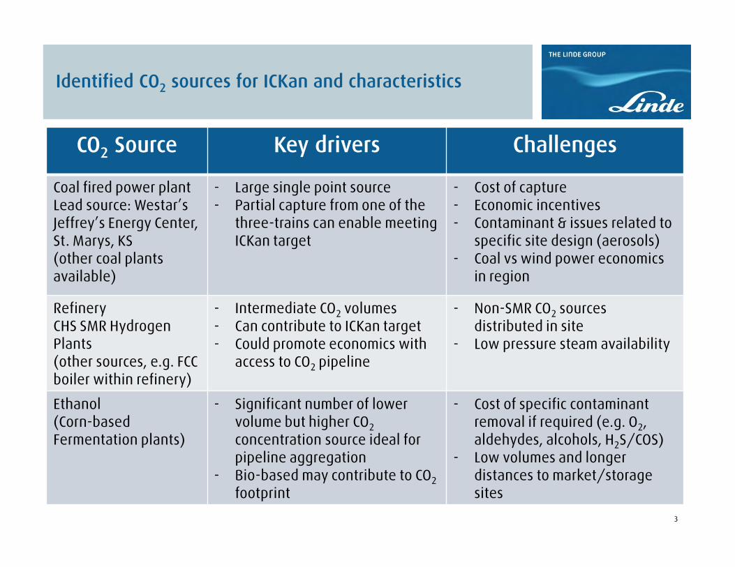
Identified CO2 sources for ICKan and characteristics
CO2 Source Key drivers Challenges
Coal fired power plantLead source: Westar’s Jeffrey’s Energy Center, St. Marys, KS(other coal plants available)
- Large single point source- Partial capture from one of the
three-trains can enable meeting ICKan target
- Cost of capture- Economic incentives- Contaminant & issues related to
specific site design (aerosols)- Coal vs wind power economics
in region
RefineryCHS SMR Hydrogen Plants(other sources, e.g. FCC boiler within refinery)
- Intermediate CO2 volumes- Can contribute to ICKan target- Could promote economics with
access to CO2 pipeline
- Non-SMR CO2 sources distributed in site
- Low pressure steam availability
Ethanol(Corn-based Fermentation plants)
- Significant number of lower volume but higher CO2concentration source ideal for pipeline aggregation
- Bio-based may contribute to CO2footprint
- Cost of specific contaminant removal if required (e.g. O2, aldehydes, alcohols, H2S/COS)
- Low volumes and longer distances to market/storage sites
4
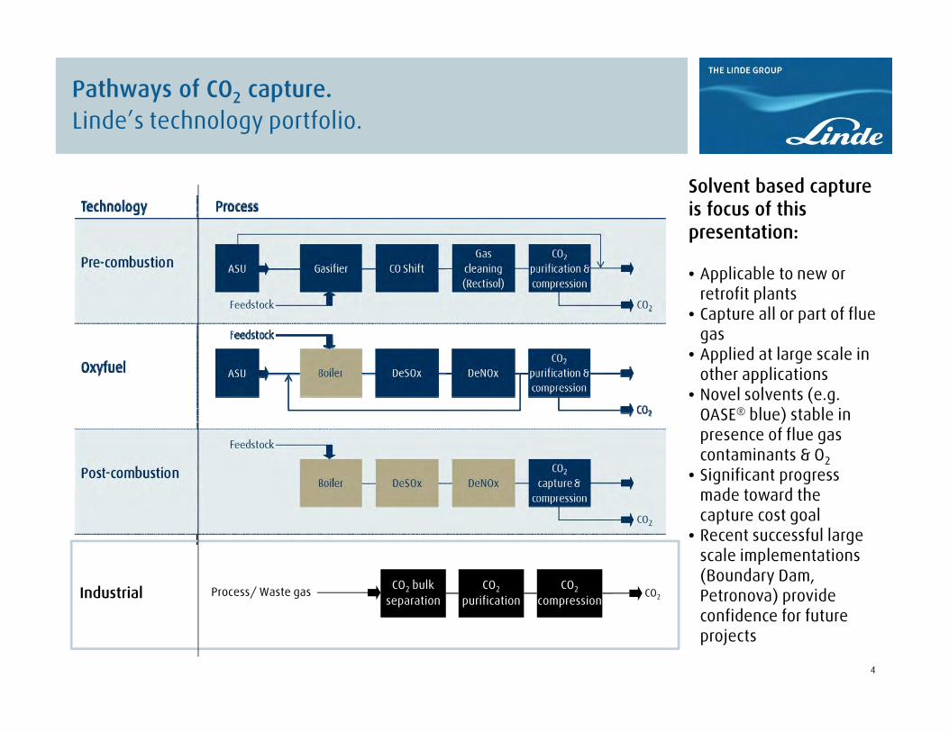
Pathways of CO2 capture.Linde’s technology portfolio.
iCCUS Workshop Berlin – CCUS at the Linde Group
Industrial
Solvent based capture is focus of this presentation:
• Applicable to new or retrofit plants
• Capture all or part of flue gas
• Applied at large scale in other applications
• Novel solvents (e.g. OASE® blue) stable in presence of flue gas contaminants & O2
• Significant progress made toward the capture cost goal
• Recent successful large scale implementations (Boundary Dam, Petronova) provide confidence for future projects
CO2 bulkseparation
CO2
purificationCO2
compressionCO2Process/ Waste gas
5
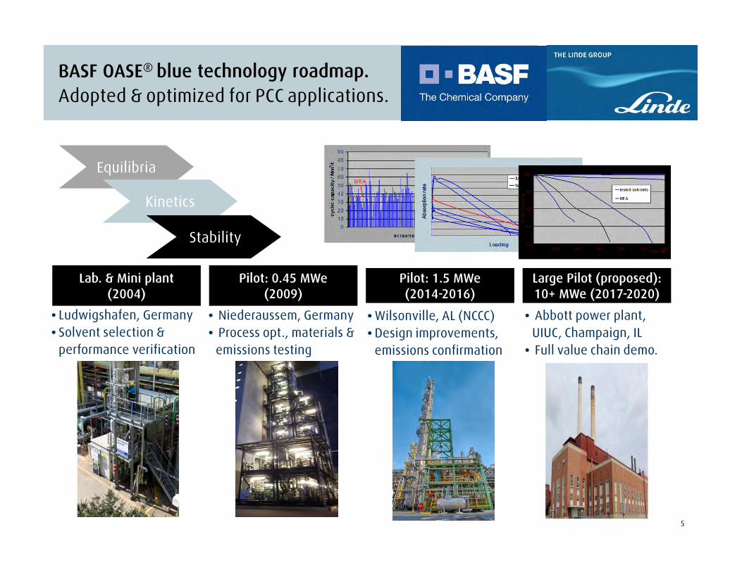
BASF OASE® blue technology roadmap.Adopted & optimized for PCC applications.
Equilibria
Kinetics
Stability
Lab. & Mini plant (2004)
Pilot: 0.45 MWe(2009)
Pilot: 1.5 MWe(2014-2016)
• Ludwigshafen, Germany• Solvent selection &
performance verification
• Niederaussem, Germany• Process opt., materials &
emissions testing
• Wilsonville, AL (NCCC)• Design improvements,
emissions confirmation
Large Pilot (proposed): 10+ MWe (2017-2020)
• Abbott power plant, UIUC, Champaign, IL
• Full value chain demo.

6
Linde-BASF progress toward lowering the cost of capture
0
0.5
1
1.5
2
2.5
3
3.5
4
Reference MEA Novel solvent Novel process Internal heatintegration
Power plantheat
integration
Additionalwaste heat
recovery
Regenerator steam in GJ/MT CO2
Tested & validatedPower plant specific concepts
Capex reduction:- High capacity structured packing
(smaller diameter absorbers)- Higher pressure regeneration
(Reduced CO2 compressor cost)- Novel lower cost equipment
(e.g. reboiler, inter-stage heater)
Electrical energy reduction:- CO2 compression power by
operating at higher regeneratorpressure
Other features for lower Opex:- Reduced solvent inventory- Fast dynamics for load following
Reducing low pressure steam consumption:
77
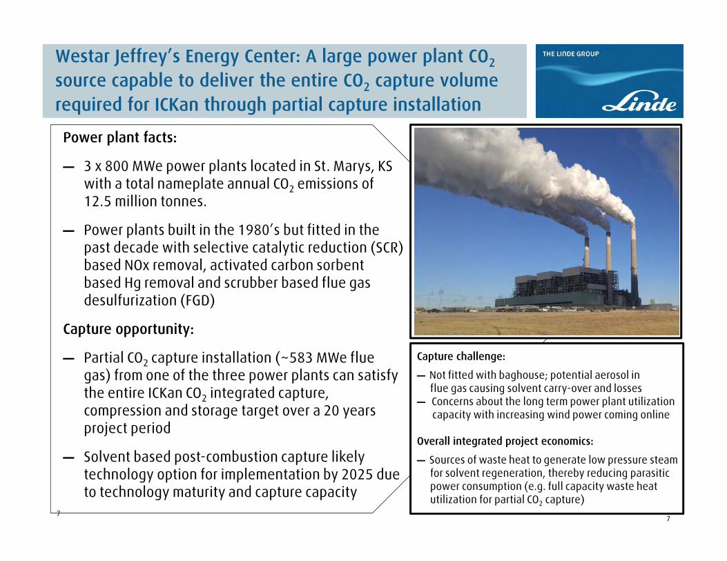
Westar Jeffrey’s Energy Center: A large power plant CO2
source capable to deliver the entire CO2 capture volume required for ICKan through partial capture installation
Power plant facts:
― 3 x 800 MWe power plants located in St. Marys, KS with a total nameplate annual CO2 emissions of 12.5 million tonnes.
― Power plants built in the 1980’s but fitted in the past decade with selective catalytic reduction (SCR) based NOx removal, activated carbon sorbent based Hg removal and scrubber based flue gas desulfurization (FGD)
Capture opportunity:
― Partial CO2 capture installation (~583 MWe flue gas) from one of the three power plants can satisfy the entire ICKan CO2 integrated capture, compression and storage target over a 20 years project period
― Solvent based post-combustion capture likely technology option for implementation by 2025 due to technology maturity and capture capacity
7
Capture challenge:
― Not fitted with baghouse; potential aerosol in flue gas causing solvent carry-over and losses
― Concerns about the long term power plant utilization capacity with increasing wind power coming online
Overall integrated project economics:
― Sources of waste heat to generate low pressure steamfor solvent regeneration, thereby reducing parasitic power consumption (e.g. full capacity waste heat utilization for partial CO2 capture)

8
Westar Jeffrey’s Energy Center: Preliminary CO2 capture assessment/Design basis
CO2 product:
― 2.5 million MT (20 yrs) or 7500 MTPD
― 90% capture efficiency
― 99.7+% purity (<100 ppmv Oxygen)
― 150 bars delivery pressure at site boundary
Flue gas processed:
― Target flue gas flow rate: 2063 MT/hr (wet)
― Flue gas composition: CO2 10.8% wet; 13.2%dry
O2 5.1% wet; 6.3% dry
― Target capture plant capacity: 583 MWe (~73% of Unit 1)
Operating requirements:
― Regenerator LP steam (4.8 bar): 1.16 tons/ton CO2
― Electrical power: 129 kW/ton CO2 (40 MW)
― Cooling water: 112 m3/ton CO2 (36,000 m3/hr)
8

9
Power plant block flow diagram showing potential waste heat extraction to generate LP steam for PCC plant
SECONDARY AIR FANS
COAL FEED
PU
LVE
RIZ
ED
CO
AL
BO
ILE
R
PRIMARY AIR FANS
INFILTRATION AIR
SCR
BOILER
FEEDWATER
HP ST
FEEDWATER HEATER SYSTEM
MAIN STEAM
COLD REHEAT
HOT REHEAT
IP ST LP ST
CONDENSER
CO2 CAPTURE & COMPRESSION PLANT
Dry ESP FGD
ID FANS
LIMESTONE SLURRY
CO2 COMPR.
TO STACK
MAKEUP WATER
OXIDATION AIR
GYPSUM
BOTTOM ASH
FLY ASH
CO2 PRODUCT
EL. POWER GENERATOR
10
8a
7
5
21
43
6
9
1413
1512
1611
23
25
24
26
19
1817
21
20
22
Absorber
Treated flue gasto stack
CO2to Compression
Reboiler
Desorber
Condenser
Make-up water
SolventStorage
Tank
Interstage Cooler
Flue gas
DCC
NaOH Tank
Rich/LeanSolvent
Hex
Flue gas blower
Solvent Cooler
Interstage Heater
LP_Steam
Condensatereturn
LP/IP_Steam
Condensate return
Solvent Filter
Water Wash
Water Wash
WaterCooler
Cooler
Separator
FROM ROTARY
AIR BLOWER
HEATED AIR TO BOILER
8 9a
ACI
Waste heat extraction 1: Heat recovery prior to entering FGDWaste heat extraction 2: Heat recovery From flue gas leaving SCR prior to entering activated carbon injection for Hg removal
Waste heat extraction 3: Heat recovery from fly ash hopper
IP steam is split into two at cross-over point to two separate LPturbines (shown as 1 in figure)
1010
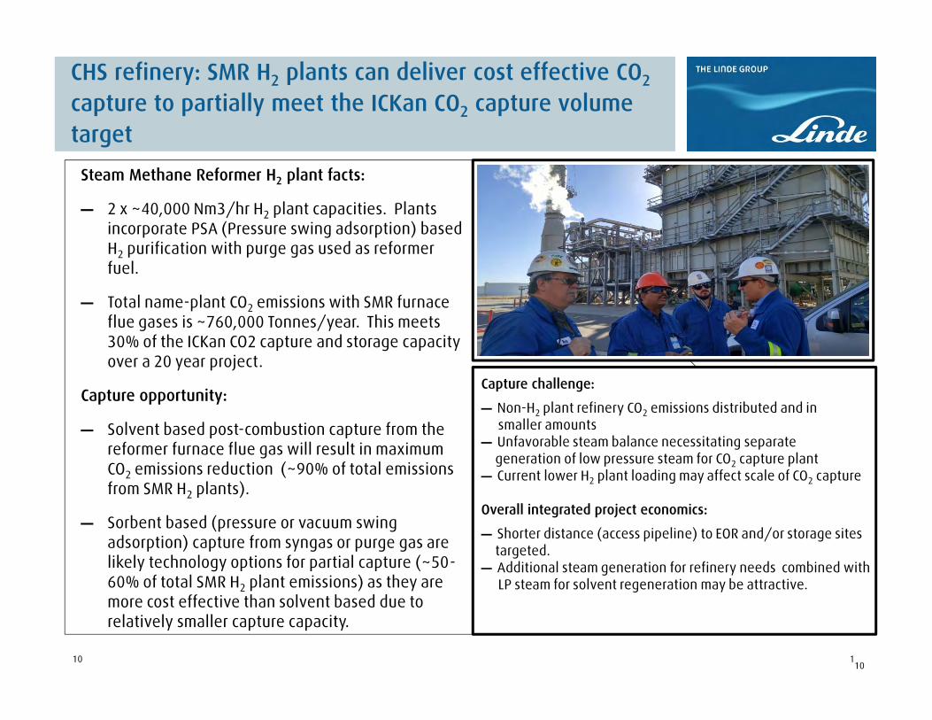
CHS refinery: SMR H2 plants can deliver cost effective CO2
capture to partially meet the ICKan CO2 capture volume target
Steam Methane Reformer H2 plant facts:
― 2 x ~40,000 Nm3/hr H2 plant capacities. Plants incorporate PSA (Pressure swing adsorption) based H2 purification with purge gas used as reformer fuel.
― Total name-plant CO2 emissions with SMR furnace flue gases is ~760,000 Tonnes/year. This meets 30% of the ICKan CO2 capture and storage capacity over a 20 year project.
Capture opportunity:
― Solvent based post-combustion capture from the reformer furnace flue gas will result in maximum CO2 emissions reduction (~90% of total emissions from SMR H2 plants).
― Sorbent based (pressure or vacuum swing adsorption) capture from syngas or purge gas are likely technology options for partial capture (~50-60% of total SMR H2 plant emissions) as they are more cost effective than solvent based due to relatively smaller capture capacity.
10
Capture challenge:
― Non-H2 plant refinery CO2 emissions distributed and in smaller amounts
― Unfavorable steam balance necessitating separate generation of low pressure steam for CO2 capture plant
― Current lower H2 plant loading may affect scale of CO2 capture
Overall integrated project economics:
― Shorter distance (access pipeline) to EOR and/or storage sites targeted.
― Additional steam generation for refinery needs combined withLP steam for solvent regeneration may be attractive.

11
CHS refinery SMR H2 plant CO2 capture: Preliminary assessment and design basis
CO2 product:
― 1872 MTPD (~13.6 million tons over 20 yrs)
― 90% capture efficiency
― 99.7+% purity (<100 ppmv Oxygen)
― 150 bars delivery pressure at site boundary
Flue gas processed (mixed from 2 SMR’s):
― Target flue gas flow rate: 362.7 MT/hr (wet)
― Flue gas composition: CO2 15.8% wet; 19.1%dry
O2 2.2% wet; 2.7% dry
― Target capture plant capacity: 100% of available SMR H2 plant furnace flue gases (2 plants)
Operating requirements:
― Regenerator LP steam (4.8 bar): 1.17 tons/ton CO2
― Electrical power: 123 kW/ton CO2 (9,600 kW)
― Cooling water: 115 m3/ton CO2 (9000 m3/hr)

12
Questions?
Thank you for your attention!
Back-up slides

13
Linde has performed number of large scale studies/ process concepts and engineering assessment tailor-made based on end-customer requirements

![2012 Determination - Home - Linde España | Linde España · Linde financiaL highLights [1] Linde financiaL highL ights Linde financial highlights January to december 2012 2011 change](https://static.fdocuments.in/doc/165x107/5f9a3ff2e98e362cc85a459b/2012-determination-home-linde-espaa-linde-espaa-linde-financial-highlights.jpg)