2017 GAS GAS - Offroadracing Pilz · The exhaust pipe and other elements reach high temperatures...
77
Transcript of 2017 GAS GAS - Offroadracing Pilz · The exhaust pipe and other elements reach high temperatures...


2017 GAS GASAll rights reservedReprinting and reproduction of any kind, either in whole or in part, is prohibited without the written permission of the copyright holder.The company has the right, without prior notice, to change the technical content of the products.The models in the images may appear with special equipment that does not come with the standard model.
Edition 01/06/2017
Owner's Manual
-3-
General information ................................................................................................................................................................. 7IntroductIon ...............................................................................................................................................................................8LeGAL notIceS ...............................................................................................................................................................................8notIceS And wArnInGS...............................................................................................................................................................8PreLImInAry wArnInGS ..............................................................................................................................................................9LocaTion of componEnTs Ec 2T 250/300cc 2018 .................................................................................................................10LocaTion of componEnTs Ec 2T 250/300cc 2018 .................................................................................................................11IdentIfIcAtIon ............................................................................................................................................................................ 13SteerInG Lock ............................................................................................................................................................................. 13SPecIfIcAtIonS ............................................................................................................................................................................ 14ELEcTRic diagRam foR 250/300cc modELs ...........................................................................................................................17
engine ................................................................................................................................................................................. 20muLTifuncTion gaugE (Ec modELs onLy) .............................................................................................................................23
mode push-button ..............................................................................................................................................................23adjustment push-button .....................................................................................................................................................23
HomoLoGAtIon .......................................................................................................................................................................... 24operatinG instructions ........................................................................................................................................................... 26
StArtInG Procedure ................................................................................................................................................................27BREaking-in ................................................................................................................................................................................. 27dAILy InSPectIon before rIdInG .............................................................................................................................................28cLeAnInG ...................................................................................................................................................................................... 32StorAGe ........................................................................................................................................................................................ 33obd oPerAtIon ........................................................................................................................................................................... 33
maintenance ............................................................................................................................................................................... 35mAIntenAnce tAbLe ................................................................................................................................................................... 36mAIntenAnce .............................................................................................................................................................................. 37
1.-clutch .............................................................................................................................................................................. 372.-clutch discs ..................................................................................................................................................................... 373.-Throttle cable ..................................................................................................................................................................374.-spark plug ....................................................................................................................................................................... 375.-air filter .......................................................................................................................................................................... 386.-carburettor ..................................................................................................................................................................... 407.-Transmission oil ..............................................................................................................................................................408.-piston and ring ................................................................................................................................................................419. cylinder head, cylinder and exhaust valve ......................................................................................................................4110.-Exhaust system .............................................................................................................................................................4111.-muffler fibre ..................................................................................................................................................................4212.-connecting rod and bearings ........................................................................................................................................4313.-kick-starter and gear shift pedal ...................................................................................................................................4314.-Rubber gasket exhaust/silencer ....................................................................................................................................4315.-motor bearings .............................................................................................................................................................4316.-coolant ......................................................................................................................................................................... 4317.-Radiator tube and connections .....................................................................................................................................4518.-Brakes adjustment ........................................................................................................................................................4519.-Brakes wear ..................................................................................................................................................................4620.-Brake fluid ..................................................................................................................................................................... 4821.-Brake fluid level.............................................................................................................................................................4822.-Brake pump piston and dust cover (front and rear) ......................................................................................................48
Contents
Owner's Manual
-4-
23.-calliper piston and dust cover (all callipers) ..................................................................................................................4924.-Brake hoses ................................................................................................................................................................... 4925 and 26.-spokes and wheels ............................................................................................................................................4927.-chain guide ................................................................................................................................................................... 4928.-chain guide wear ..........................................................................................................................................................4929.- chain guide shoe ..........................................................................................................................................................4930.-front suspension ..........................................................................................................................................................5031.-front suspension oil ......................................................................................................................................................5132.-Bolts, nuts and fasteners ...............................................................................................................................................5133.-petrol tube .................................................................................................................................................................... 5134.-fuel system ................................................................................................................................................................... 5235.-steering head adjustment .............................................................................................................................................5236.-general lubrication .......................................................................................................................................................5337.-steering bearing ............................................................................................................................................................5338.-Wheel bearing ..............................................................................................................................................................5339.-swingarm and linkage ...................................................................................................................................................5340.-Rear suspension ............................................................................................................................................................5341.-chain ............................................................................................................................................................................. 5642.-Tires .............................................................................................................................................................................. 5643.-Battery charge ...............................................................................................................................................................57
settinGs ........................................................................................................................................................................................ 58IntroductIon ............................................................................................................................................................................. 59cArburAtor SettInG * for Xc modeL ....................................................................................................................................59
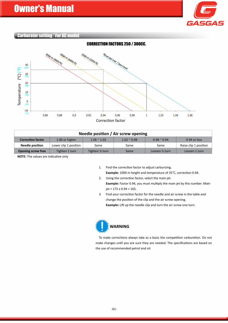
opening of the throttle valve and influences ......................................................................................................................59idle jet and mixing screw ....................................................................................................................................................59Reference carburetion (competition only) ..........................................................................................................................60carburettor needle .............................................................................................................................................................60main jet .............................................................................................................................................................................. 60correction factors 250 / 300cc. ...........................................................................................................................................61
SecondAry trAnSmISSIon rAtIo .............................................................................................................................................62SuSPenSIon SettInG ..................................................................................................................................................................62
available settings ................................................................................................................................................................62suspEnsion settings ..........................................................................................................................................................63static sag ............................................................................................................................................................................. 65correction according to type of terrain ...............................................................................................................................65adjusting your motorcycle ..................................................................................................................................................65
SuSPenSIon SettInG ..................................................................................................................................................................66centrIfuGAL eXternAL AdjuStment SyStem .......................................................................................................................67
troubleshootinG ....................................................................................................................................................................... 68Warranty manual ..................................................................................................................................................................... 74
Contents

Owner's Manual
-5-
Owner's Manual
-6-
This page has been left blank intentionally.
Owner's Manual
-7-
General infOrMatiOn
Owner's Manual
-8-
introductionGas Gas thanks you for your trust.
By choosing the new Gas Gas ec 2018 or Xc 2018 you have just joined the great Gas Gas team, and as a user of the number one brand of off-road bikes, you deserve the distinguished care that we would like to offer you, both after purchasing your Gas Gas and in the explanations that we set out in this manual.
your Gas Gas ec 2018 or Xc 2018 is a bike designed for high-level competition, it is the fruit of many years of competition and experience in demanding disciplines. The many successes achieved by the great riders of our Gas Gas bikes has provided the basic data to be able to create these high-end motorcycles. Exclusive Gas Gas motorcycles that have three key factors: reliability, high performance and good stability.
congratulations because your choice has undoubtedly been the right one. With your skills in handling your Gas Gas and with the proper preparation and the corresponding reviews, vital for your Gas Gas to be highly reliable, you can enjoy the most comfortable and fulfilling motorcycling.
Thank you for your trust and welcome to Gas Gas.
notices and warningsplease read this manual thoroughly, paying particular attention to the following warnings:
DanGer
notices about a danger that leads to serious injury or even death.
WarninG
notices regarding danger that could result in personal injury and/or damage to the vehicle.
legal notices
in the interest of technical development Gas Gas reserves the right to modify the construction, equipment and accessories of the motorcycle without prior notice. measurements, weight and power data are understood to include the respective tolerances. depending on the volume of equipment and accessories of your Gas Gas , as well as in the approved versions in accordance with the different laws of each state, there may be variations with respect to the descriptions and illustrations. Therefore, the photographs contained in this manual may not correspond to the model purchased. for this reason no liability shall be derived for error, printing error or omission.
Owner's Manual
-9-
Preliminary warnings
DanGer
Three out of four fatal accidents are due to head injuries. The risk of brain injury is three times greater if no helmet is used. always wear an approved helmet, the probability of remaining unscathed in the event of an accident is increased by 20%. it is also recommended to use eye protection as well as gloves, boots and other protective items that should be in perfect condition.
never carry a passenger. your Gas Gas is not approved for this purpose, nor does it have space on the seat, handlebars or footrests for the passenger. in addition, the extra weight can impair handling.
avoid modifying your Gas Gas with non-original accessories and do not remove the original elements, these changes could affect the stability and handling, making the vehicle dangerous or illegal. The use of original spare parts and accessories or parts approved by Gas Gas is recommended. it is an essential condition for maintaining the warranty.
your Gas Gas has been designed for off-road use, it has not been designed for long journeys on the road or motorway. such use may result in damage to the engine due the high revolutions and the tires are not suitable for use on paved surfaces. it has not been designed for urban use either. Long stops at traffic lights in the city could cause engine overheating.
keep your Gas Gas in good condition. To avoid any problems, inspect your motorcycle before every use, and perform all maintenance as recommended in this manual. after a fall, check that the main elements have not been damaged. Riding a motorcycle in poor condition can cause an accident with serious injuries and even death.
DanGer
The exhaust pipe and other elements reach high temperatures during use and take time to cool down once the engine has been turned off. avoid handling or touching anything during this period. The use of shorts is not recommended, since it can cause burns to the legs.
DanGer
avoid wearing loose clothing that could get caught on parts of the vehicle or the surroundings. although total safety is impossible, the use of adequate equipment reduces the possibility and/or severity of injuries.
Owner's Manual
-10-
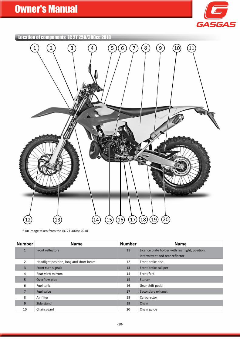
location of components eC 2t 250/300cc 2018
number name number name1 front reflectors 11 Licence plate holder with rear light, position,
intermittent and rear reflector
2 Headlight position, long and short beam 12 front brake disc
3 front turn signals 13 front brake calliper
4 Rear-view mirrors 14 front fork
5 overflow pipe 15 starter
6 fuel tank 16 gear shift pedal
7 fuel valve 17 secondary exhaust
8 air filter 18 carburettor
9 side stand 19 chain
10 chain guard 20 chain guide
* an image taken from the Ec 2T 300cc 2018
1 2 3 4 5 6 7 8 9 10 11
12 13 14 15 16 17 18 19 20
Owner's Manual
-11-
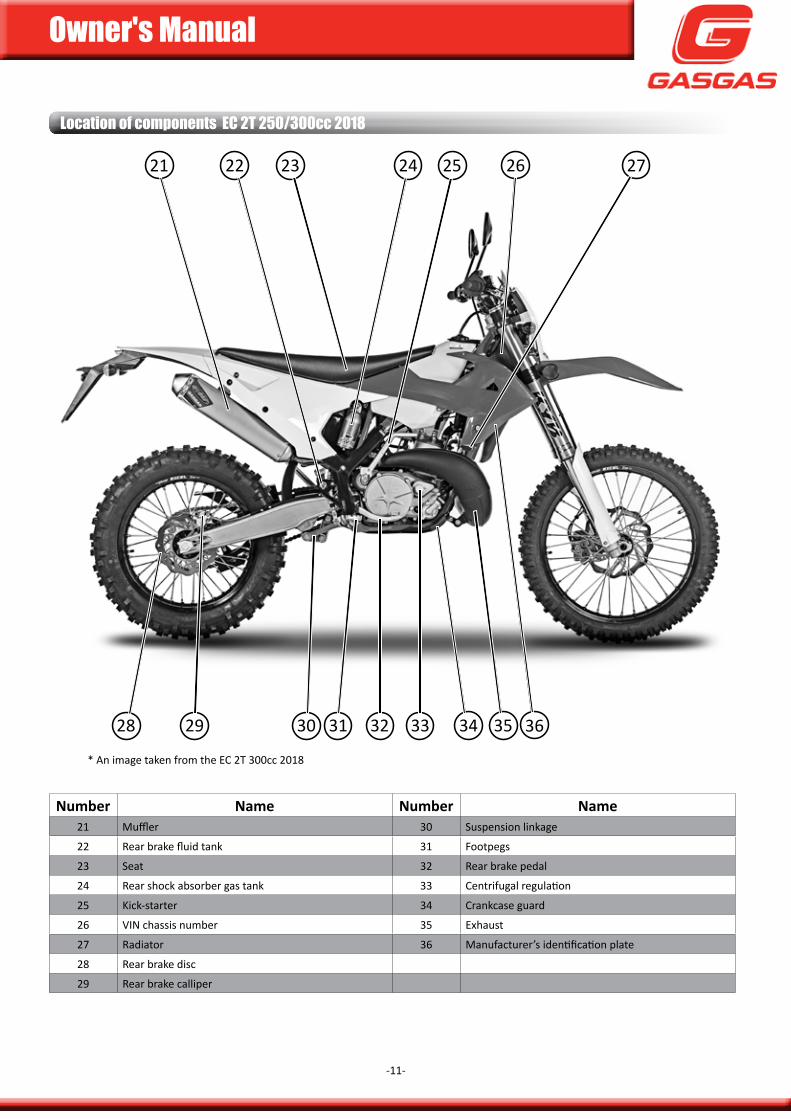
location of components eC 2t 250/300cc 2018
* an image taken from the Ec 2T 300cc 2018
number name number name21 muffler 30 suspension linkage
22 Rear brake fluid tank 31 footpegs
23 seat 32 Rear brake pedal
24 Rear shock absorber gas tank 33 centrifugal regulation
25 kick-starter 34 crankcase guard
26 Vin chassis number 35 Exhaust
27 Radiator 36 manufacturer’s identification plate
28 Rear brake disc
29 Rear brake calliper
21 22 23 24 25 26 27
28 29 30 31 32 33 34 35 36
Owner's Manual
-12-
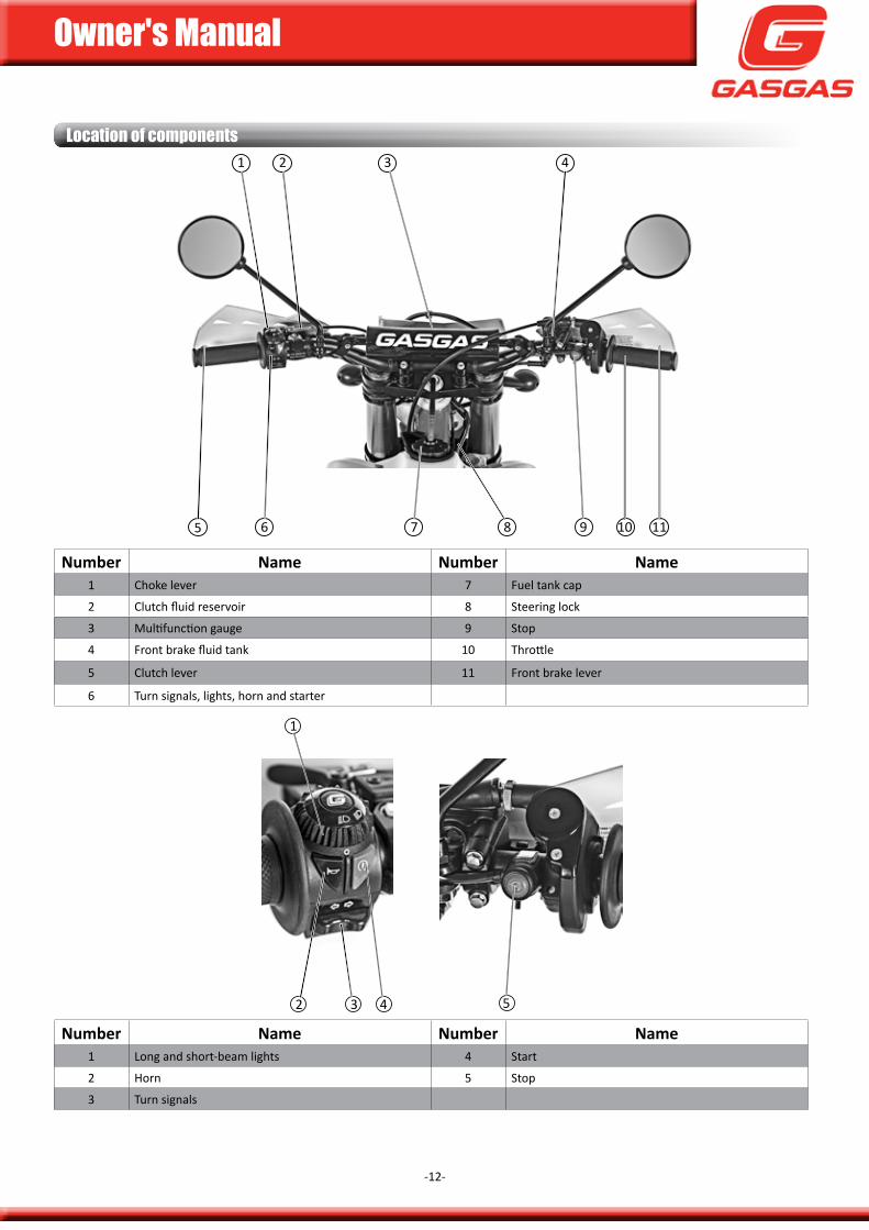
number name number name1 choke lever 7 fuel tank cap
2 clutch fluid reservoir 8 steering lock
3 multifunction gauge 9 stop
4 front brake fluid tank 10 Throttle
5 clutch lever 11 front brake lever
6 Turn signals, lights, horn and starter
location of components
number name number name1 Long and short-beam lights 4 start
2 Horn 5 stop
3 Turn signals
1 2 3 4
5 6 7 8 9 10 11
1
2 3 4 5
Owner's Manual
-13-
Identification
Steering lock
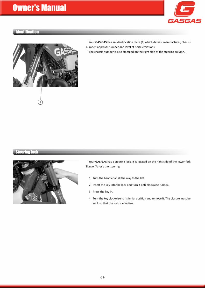
your Gas Gas has an identification plate (1) which details: manufacturer, chassis number, approval number and level of noise emissions.
The chassis number is also stamped on the right side of the steering column.
your Gas Gas has a steering lock. it is located on the right side of the lower fork flange. To lock the steering:
1. Turn the handlebar all the way to the left.
2. insert the key into the lock and turn it anti-clockwise ⅛ back.
3. press the key in.
4. Turn the key clockwise to its initial position and remove it. The closure must be sunk so that the lock is effective.
1
Owner's Manual
-14-
Specifications
enG
ine
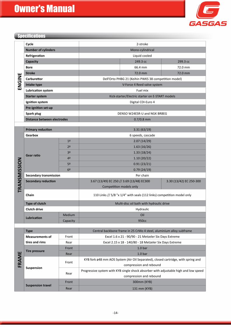
cycle 2-stroke
number of cylinders mono-cylindrical
Refrigeration Liquid cooled
capacity 249.3 cc 299.3 cc
bore 66.4 mm 72.0 mm
stroke 72.0 mm 72.0 mm
Carburettor dell’orto pHBg 21 (keihin pWks 38 competition model)
intake type V-force 4 Reed valve system
Lubrication system fuel mix
starter system kick-starter/Electric starter on E-sTaRT models
Ignition system digital cdi-Euro 4
Pre-ignition set-up
spark plug dEnso W24EsR-u and ngk BR8Eg
Distance between electrodes 0.7/0.8 mm
tran
smis
sio
n
Primary reduction 3.31 (63/19)
Gearbox 6 speeds, cascade
Gear ratio
1ª 2.07 (14/29)
2ª 1.63 (16/26)
3ª 1.33 (18/24)
4ª 1.10 (20/22)
5ª 0.91 (23/21)
6ª 0.79 (24/19)
secondary transmission per chain
Secondary reduction 3.67 (13/49) Ec 250 // 3.69 (13/48) Ec300competition models only
3.30 (13/42) Ec 250-300
chain 110 Links // 5/8 "x 1/4" with seals (112 links) competition model only
type of clutch multi-disc oil bath with hydraulic drive
clutch drive Hydraulic
Lubricationmedium oil
capacity 950cc
fram
e
type central backbone frame in 25 crmo 4 steel, aluminium alloy subframe
measurements of tires and rims
front Excel 1.6 x 21 - 90/90 - 21 metzeler six days Extreme
Rear Excel 2.15 x 18 - 140/80 - 18 metzeler six days Extreme
tire pressurefront 1.0 bar
Rear 1.0 bar
suspension
frontkyB fork ø48 mm aos system (air oil separated), closed cartridge, with spring and
compression and rebound
Rearprogressive system with kyB single shock absorber with adjustable high and low speed
compression and rebound
suspension travelfront 300mm (kyB)
Rear 131 mm (kyB)
Owner's Manual
-15-
Specifications
250 300
fram
e
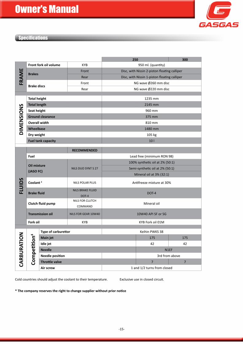
front fork oil volume kyb 950 ml. (quantity)
brakesfront disc, with nissin 2-piston floating calliper
Rear disc, with nissin 1-piston floating calliper
brake discsfront ng wave Ø260 mm disc
Rear ng wave Ø220 mm disc
Dim
ensi
on
s
total height 1235 mm
total length 2145 mm
seat height 960 mm
Ground clearance 375 mm
overall width 810 mm
Wheelbase 1480 mm
Dry weight 105 kg
fuel tank capacity 10 l
flu
iDs
recommenDeD
fuel Lead free (minimum Ron 98)
oil mixture(Jaso fc)
nILS duo Synt S 27
100% synthetic oil at 2% (50:1)
semi-synthetic oil at 2% (50:1)
mineral oil at 3% (32:1)
coolant 2 nILS PoLAr PLuS antifreeze mixture at 30%
Brake fluidnILS brAke fLuId
dot-4dot-4
Clutch fluid pumpnILS for cLutcH
commAndmineral oil
transmission oil nILS for GeAr 10w40 10W40 api sf or sg
fork oil kyb kyB fork oil 01m
carb
ura
tio
n
Com
petiti
on4
Type of carburettor keihin PwkS 38
main jet 175 175
idle jet 42 42
needle n1ef
Needle position 3rd from above
Throttle valve 7 7
air screw 1 and 1/2 turns from closed cold countries should adjust the coolant to their temperature. Exclusive use in closed circuit.
* The company reserves the right to change supplier without prior notice
Owner's Manual
-16-
Owner's Manual
-17-
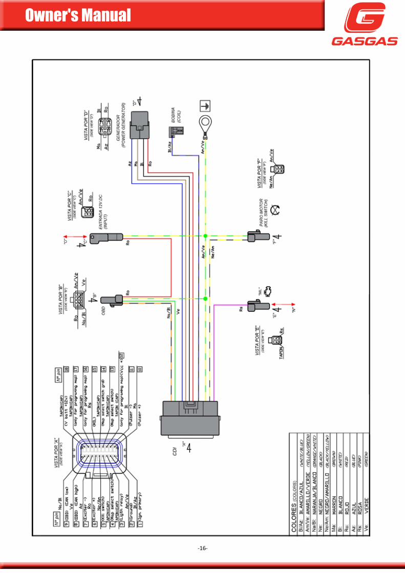
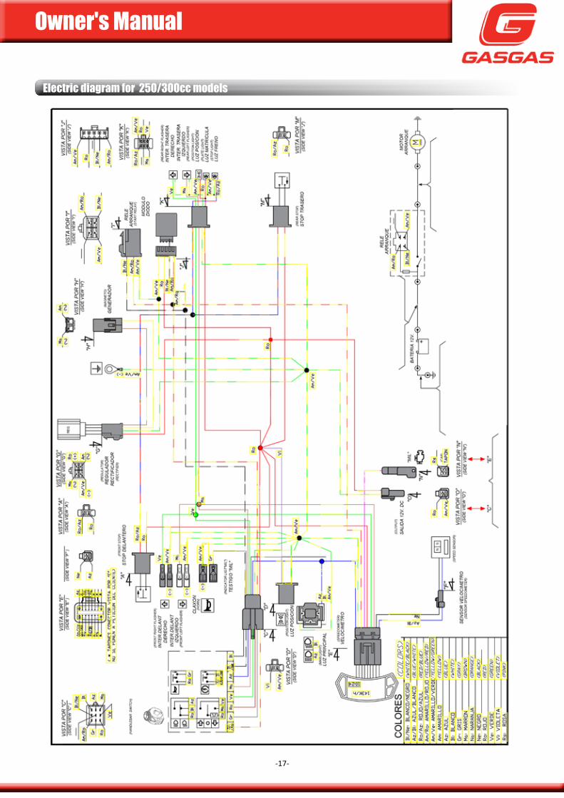
electric diagram for 250/300cc models
Owner's Manual
-18-
Owner's Manual
-19-
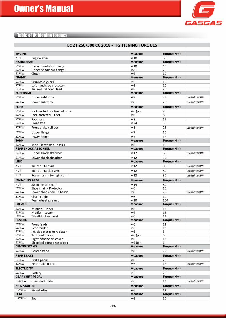
table of tightening torques
ec 2t 250/300 cc 2018 - tiGhteninG torQues
enGine measure torque (nm)nut Engine axles m10 60hanDlebar measure torque (nm)Screw Lower handlebar flange m10 40Screw upper handlebar flange m8 25Screw clutch m6 10frame measure torque (nm)Screw crankcase guard m6 10Screw Left-hand side protector m6 10Screw Tie Rod cylinder Head m8 25subframe measure torque (nm)Screw upper subframe m8 25Screw Lower subframe m8 25forK measure torque (nm)Screw fork protector - guided hose m6 (pl) 8Screw fork protector - foot m6 8Screw foot fork m8 15Screw front axle m24 35Screw front brake calliper m8 25Screw upper flange m7 15Screw Lower flange m7 12tanK measure torque (nm)Screw Tank-silentblock-chassis m6 10rear shocK absorber measure torque (nm)Screw upper shock absorber m12 60Screw Lower shock absorber m12 50linK measure torque (nm)nut Tie-rod - chassis m12 80nut Tie-rod - Rocker arm m12 80nut Rocker arm - swinging arm m12 80sWinGinG arm measure torque (nm)nut swinging arm nut m14 80Screw shoe chain - protector m6 10Screw Lower shoe chain - chassis m8 25Screw chain guide m6 10nut Rear wheel axle nut m20 100eXhaust measure torque (nm)Screw muffler - upper m6 12Screw muffler - Lower m6 12Screw silentblock exhaust m6 12plastic measure torque (nm)Screw front fender m6 12Screw Rear fender m6 12Screw inf. side plates to radiator m6 8Screw Tank and plates m6 (pl) 6Screw Right-hand valve cover m6 12Screw Electrical components box m6 (pl) 6centre stanD measure torque (nm)Screw center stand m8 25rear braKe measure torque (nm)Screw Brake pedal m8 20Screw Rear brake pump m6 12electricity measure torque (nm)Screw Battery m5 2.5Gear shift peDal measure torque (nm)
Screw gear shift pedal m6 12KicK-starter measure torque (nm)
Screw kick-starter m6 12seat measure torque (nm)
Screw seat m6 10
Owner's Manual
-20-
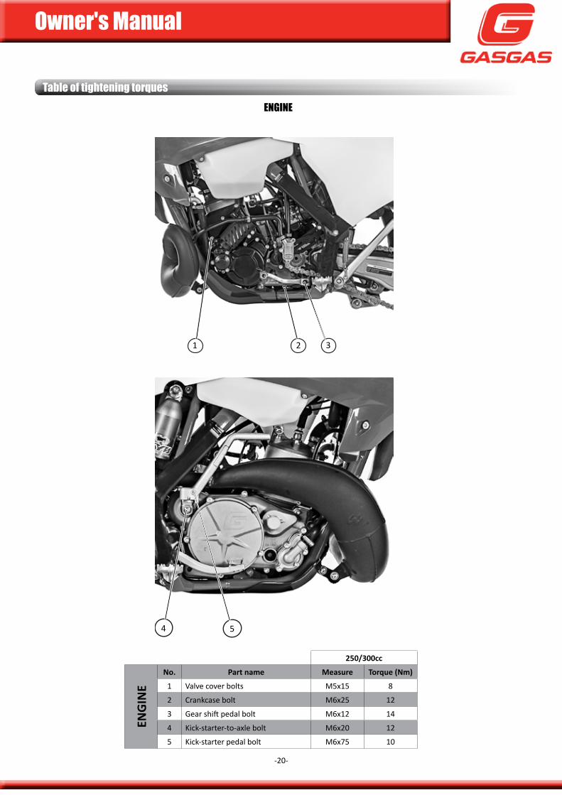
table of tightening torques
250/300cc
enG
ine
no. part name measure torque (nm)
1 Valve cover bolts m5x15 8
2 crankcase bolt m6x25 12
3 gear shift pedal bolt m6x12 14
4 kick-starter-to-axle bolt m6x20 12
5 kick-starter pedal bolt m6x75 10
enGine
4 5
2 31
Owner's Manual
-21-
table of tightening torques
1
2 3
4
5
6
7 8
9
Owner's Manual
-22-
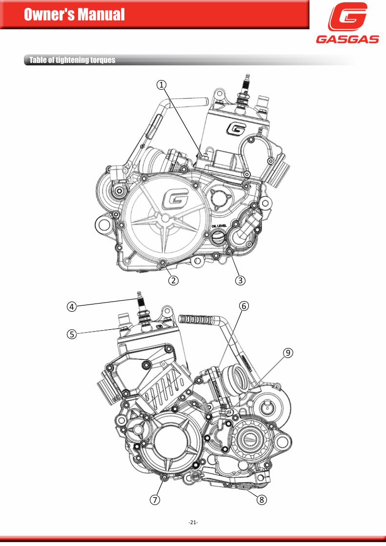
250/300cc
enG
ine
no. part name measure torque (nm)
1 cylinder nut m10 40
2 clutch cover bolt m6 12
3 Water pump drain bolt m6 8
4 spark plug - 25
5 cylinder head bolt m8 27
6 Reed block bolt m6 12
7 ignition cover bolt m6 8
8 Engine drain plug m12 15
9 oil fill bolt m12 15
- Ratchet plate bolt m6 8
- stator bolts m5 8
- ignition motor coil bolt m10 60
- selector spring fixing bolt m8 15
- primary nut m20 80
- clutch spring bolts m6 10
- Valve control support bolt m5 8
- clutch hub nut m18 80
table of tightening torques
Owner's Manual
-23-
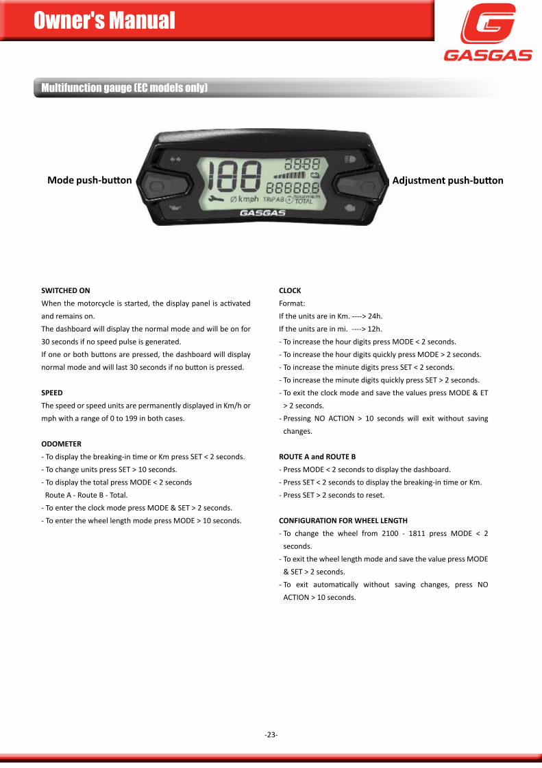
Multifunction gauge (eC models only)
sWitcheD on When the motorcycle is started, the display panel is activated and remains on. The dashboard will display the normal mode and will be on for 30 seconds if no speed pulse is generated. if one or both buttons are pressed, the dashboard will display normal mode and will last 30 seconds if no button is pressed.
speeD The speed or speed units are permanently displayed in km/h or mph with a range of 0 to 199 in both cases.
oDometer- To display the breaking-in time or km press sET < 2 seconds.- To change units press sET > 10 seconds.- To display the total press modE < 2 seconds Route a - Route B - Total.- To enter the clock mode press modE & sET > 2 seconds.- To enter the wheel length mode press modE > 10 seconds.
Adjustment push-buttonMode push-button
clocKformat:if the units are in km. ----> 24h.if the units are in mi. ----> 12h.- To increase the hour digits press modE < 2 seconds.- To increase the hour digits quickly press modE > 2 seconds.- To increase the minute digits press sET < 2 seconds.- To increase the minute digits quickly press sET > 2 seconds.- To exit the clock mode and save the values press modE & ET
> 2 seconds.- pressing no acTion > 10 seconds will exit without saving
changes.
route a and route b- press modE < 2 seconds to display the dashboard.- press sET < 2 seconds to display the breaking-in time or km.- press sET > 2 seconds to reset.
confiGuration for Wheel lenGth- To change the wheel from 2100 - 1811 press modE < 2
seconds.- To exit the wheel length mode and save the value press modE
& sET > 2 seconds.- To exit automatically without saving changes, press no
acTion > 10 seconds.
Owner's Manual
-24-
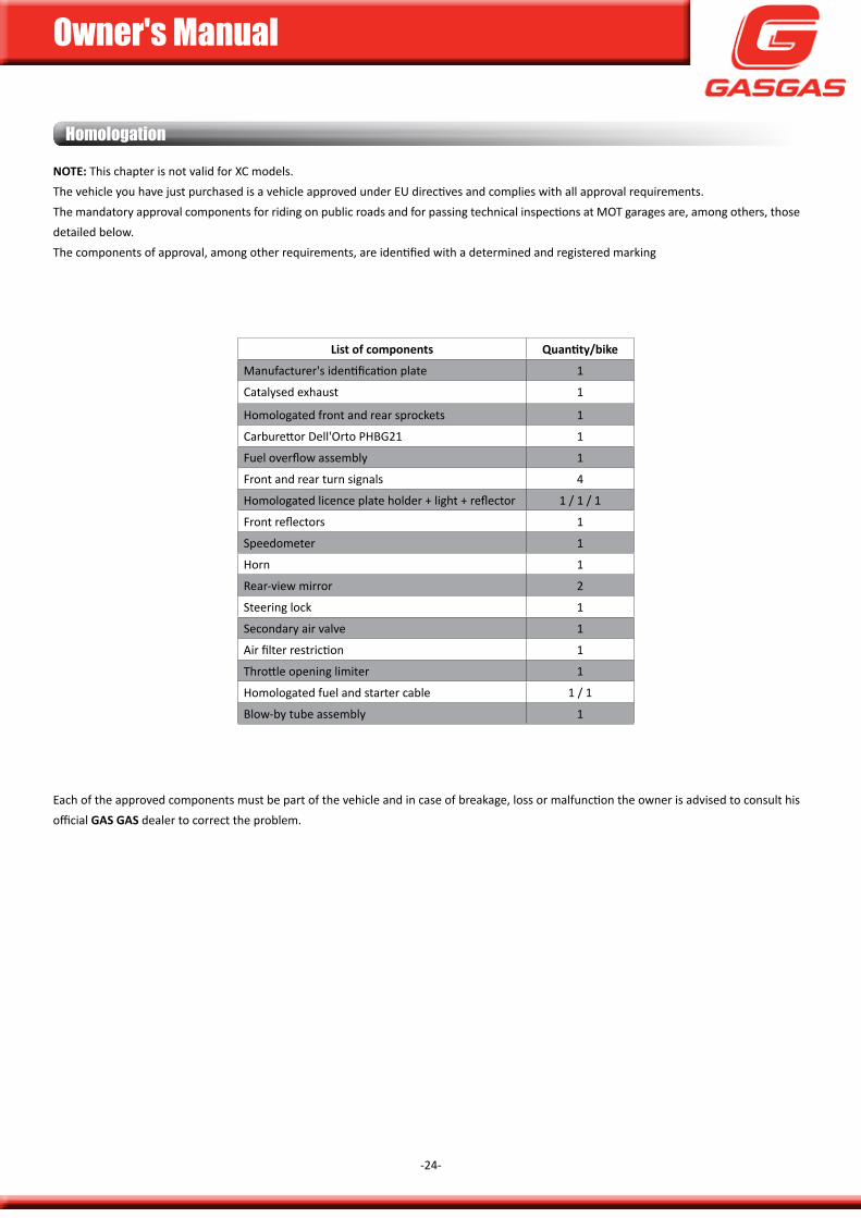
note: This chapter is not valid for Xc models.The vehicle you have just purchased is a vehicle approved under Eu directives and complies with all approval requirements.The mandatory approval components for riding on public roads and for passing technical inspections at moT garages are, among others, those detailed below.The components of approval, among other requirements, are identified with a determined and registered marking
list of components Quantity/bike
manufacturer's identification plate 1
catalysed exhaust 1
Homologated front and rear sprockets 1
carburettor dell'orto pHBg21 1
fuel overflow assembly 1
front and rear turn signals 4
Homologated licence plate holder + light + reflector 1 / 1 / 1
front reflectors 1
speedometer 1
Horn 1
Rear-view mirror 2
steering lock 1
secondary air valve 1
air filter restriction 1
Throttle opening limiter 1
Homologated fuel and starter cable 1 / 1
Blow-by tube assembly 1
Each of the approved components must be part of the vehicle and in case of breakage, loss or malfunction the owner is advised to consult his official Gas Gas dealer to correct the problem.
Homologation

Owner's Manual
-25-
Owner's Manual
-26-
This page has been left blank intentionally.
OPeratinG inStruCtiOnS
Owner's Manual
-27-
Breaking-in
it is important to carry out the breaking-in phase, by doing this you will ensure the duration and correct function of your engine in the long term. The intervals to be performed are the following:
1. from 0 to 200 km: Riding at between 50% and 75% load (throttle opening), alternately, without continued use at 75% load.
2. from 200 to 300 km: Riding the same but reaching on occasion, without
keeping it more than 5 ~ 10 seconds, at 100% load.3. from 300 to 400 km: Riding a 75% to 100% load, alternatively, without
maintaining the load stop.
4. from 400 km, increase the requirement with some escalation around 60 ~ 80 km, until reaching its full performance.
DanGer
Reckless acceleration can cause problems in the engine. Take care that you use the skills and techniques necessary in riding the motorcycle.
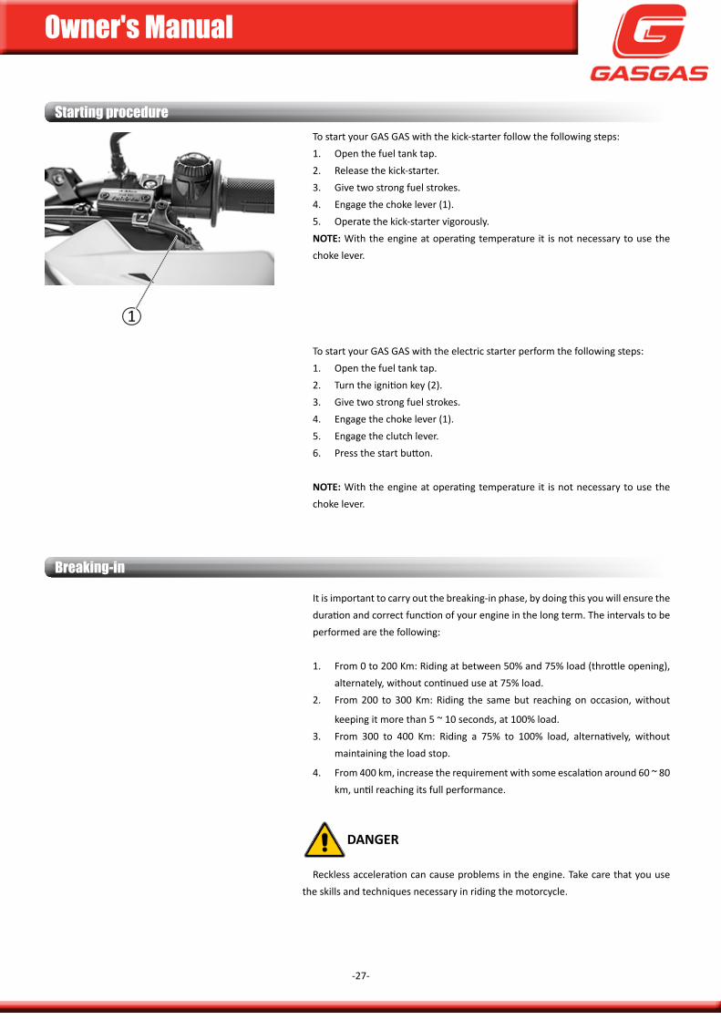
Starting procedure To start your gas gas with the kick-starter follow the following steps:1. open the fuel tank tap.2. Release the kick-starter.3. give two strong fuel strokes.4. Engage the choke lever (1).5. operate the kick-starter vigorously.note: With the engine at operating temperature it is not necessary to use the choke lever.
To start your gas gas with the electric starter perform the following steps:1. open the fuel tank tap.2. Turn the ignition key (2).3. give two strong fuel strokes.4. Engage the choke lever (1).5. Engage the clutch lever.6. press the start button.
note: With the engine at operating temperature it is not necessary to use the choke lever.
1
Owner's Manual
-28-
Daily inspection before ridingprior to each use of your Gas Gas motorcycle it is necessary to carry out the
following checks:
is there enough fuel? open the fuel cap and, by moving the motorcycle sideways with the handlebar, you will see and hear the fuel, so you will know the approximate contents.
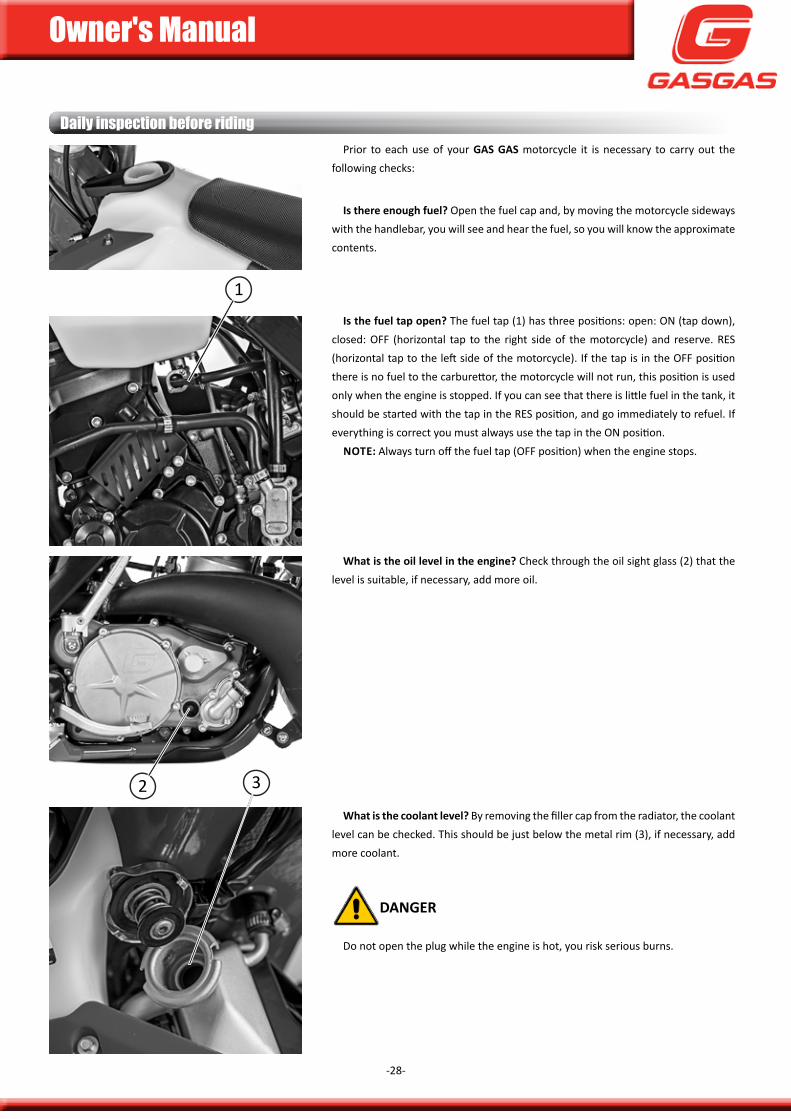
is the fuel tap open? The fuel tap (1) has three positions: open: on (tap down), closed: off (horizontal tap to the right side of the motorcycle) and reserve. REs (horizontal tap to the left side of the motorcycle). if the tap is in the off position there is no fuel to the carburettor, the motorcycle will not run, this position is used only when the engine is stopped. if you can see that there is little fuel in the tank, it should be started with the tap in the REs position, and go immediately to refuel. if everything is correct you must always use the tap in the on position.
note: always turn off the fuel tap (off position) when the engine stops.
What is the oil level in the engine? check through the oil sight glass (2) that the level is suitable, if necessary, add more oil.
What is the coolant level? By removing the filler cap from the radiator, the coolant level can be checked. This should be just below the metal rim (3), if necessary, add more coolant.
DanGer
do not open the plug while the engine is hot, you risk serious burns.
1
2 3
Owner's Manual
-29-
Daily inspection before riding
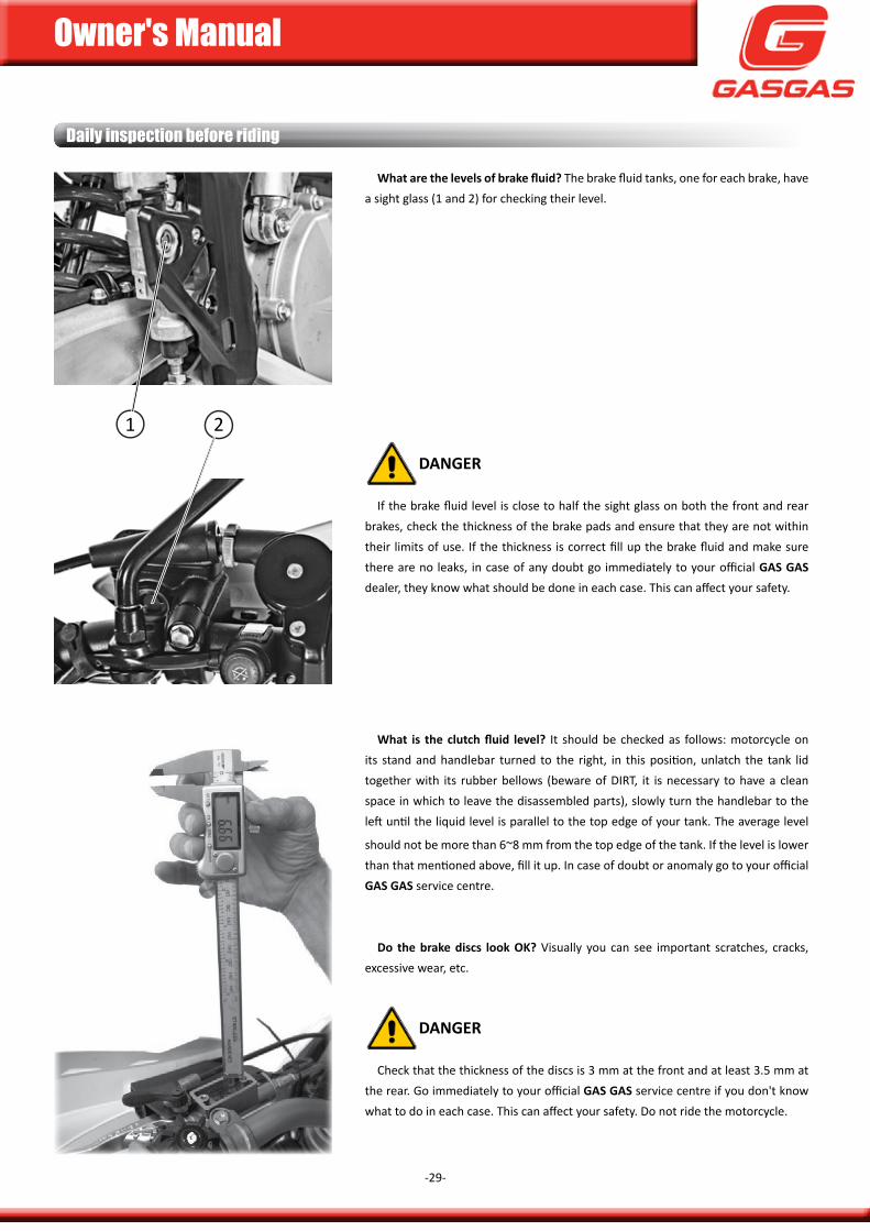
What are the levels of brake fluid? The brake fluid tanks, one for each brake, have a sight glass (1 and 2) for checking their level.
DanGer
if the brake fluid level is close to half the sight glass on both the front and rear brakes, check the thickness of the brake pads and ensure that they are not within their limits of use. if the thickness is correct fill up the brake fluid and make sure there are no leaks, in case of any doubt go immediately to your official Gas Gas dealer, they know what should be done in each case. This can affect your safety.
What is the clutch fluid level? it should be checked as follows: motorcycle on its stand and handlebar turned to the right, in this position, unlatch the tank lid together with its rubber bellows (beware of diRT, it is necessary to have a clean space in which to leave the disassembled parts), slowly turn the handlebar to the left until the liquid level is parallel to the top edge of your tank. The average level
should not be more than 6~8 mm from the top edge of the tank. if the level is lower than that mentioned above, fill it up. in case of doubt or anomaly go to your official Gas Gas service centre.
Do the brake discs look oK? Visually you can see important scratches, cracks, excessive wear, etc.
DanGer
check that the thickness of the discs is 3 mm at the front and at least 3.5 mm at the rear. go immediately to your official Gas Gas service centre if you don't know what to do in each case. This can affect your safety. do not ride the motorcycle.
1 2
Owner's Manual
-30-
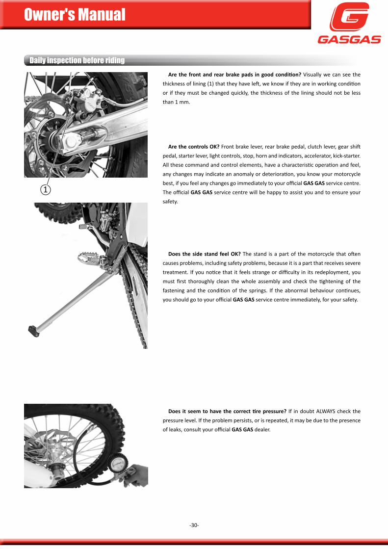
Daily inspection before ridingAre the front and rear brake pads in good condition? Visually we can see the
thickness of lining (1) that they have left, we know if they are in working condition or if they must be changed quickly, the thickness of the lining should not be less than 1 mm.
are the controls oK? front brake lever, rear brake pedal, clutch lever, gear shift pedal, starter lever, light controls, stop, horn and indicators, accelerator, kick-starter. all these command and control elements, have a characteristic operation and feel, any changes may indicate an anomaly or deterioration, you know your motorcycle best, if you feel any changes go immediately to your official Gas Gas service centre. The official Gas Gas service centre will be happy to assist you and to ensure your safety.
Does the side stand feel oK? The stand is a part of the motorcycle that often causes problems, including safety problems, because it is a part that receives severe treatment. if you notice that it feels strange or difficulty in its redeployment, you must first thoroughly clean the whole assembly and check the tightening of the fastening and the condition of the springs. if the abnormal behaviour continues, you should go to your official Gas Gas service centre immediately, for your safety.
Does it seem to have the correct tire pressure? if in doubt aLWays check the pressure level. if the problem persists, or is repeated, it may be due to the presence of leaks, consult your official Gas Gas dealer.
1
Owner's Manual
-31-
Daily inspection before riding
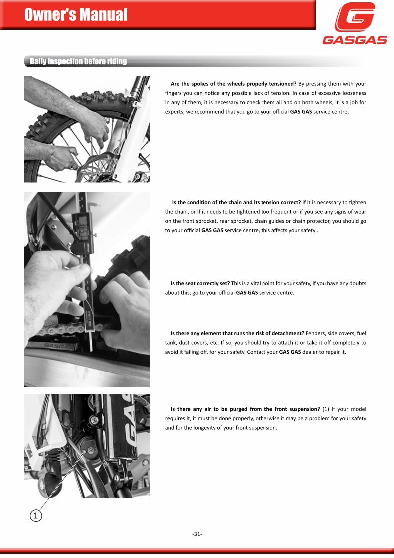
are the spokes of the wheels properly tensioned? By pressing them with your fingers you can notice any possible lack of tension. in case of excessive looseness in any of them, it is necessary to check them all and on both wheels, it is a job for experts, we recommend that you go to your official Gas Gas service centre.
Is the condition of the chain and its tension correct? if it is necessary to tighten the chain, or if it needs to be tightened too frequent or if you see any signs of wear on the front sprocket, rear sprocket, chain guides or chain protector, you should go to your official Gas Gas service centre, this affects your safety .
is the seat correctly set? This is a vital point for your safety, if you have any doubts about this, go to your official Gas Gas service centre.
is there any element that runs the risk of detachment? fenders, side covers, fuel tank, dust covers, etc. if so, you should try to attach it or take it off completely to avoid it falling off, for your safety. contact your Gas Gas dealer to repair it.
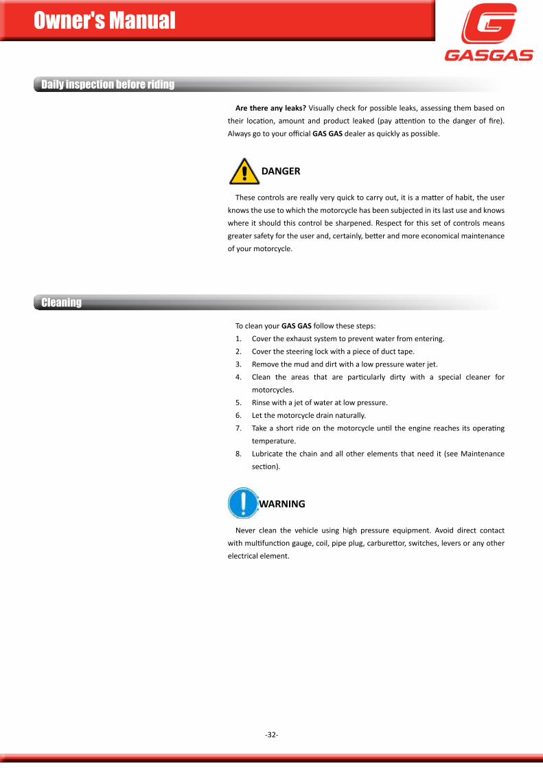
is there any air to be purged from the front suspension? (1) if your model requires it, it must be done properly, otherwise it may be a problem for your safety and for the longevity of your front suspension.
1
Owner's Manual
-32-
are there any leaks? Visually check for possible leaks, assessing them based on their location, amount and product leaked (pay attention to the danger of fire). always go to your official Gas Gas dealer as quickly as possible.
DanGer
These controls are really very quick to carry out, it is a matter of habit, the user knows the use to which the motorcycle has been subjected in its last use and knows where it should this control be sharpened. Respect for this set of controls means greater safety for the user and, certainly, better and more economical maintenance of your motorcycle.
Daily inspection before riding
Cleaning
To clean your Gas Gas follow these steps:1. cover the exhaust system to prevent water from entering.2. cover the steering lock with a piece of duct tape.3. Remove the mud and dirt with a low pressure water jet.4. clean the areas that are particularly dirty with a special cleaner for
motorcycles.5. Rinse with a jet of water at low pressure.6. Let the motorcycle drain naturally.7. Take a short ride on the motorcycle until the engine reaches its operating
temperature.8. Lubricate the chain and all other elements that need it (see maintenance
section).
WarninG
never clean the vehicle using high pressure equipment. avoid direct contact with multifunction gauge, coil, pipe plug, carburettor, switches, levers or any other electrical element.
Owner's Manual
-33-
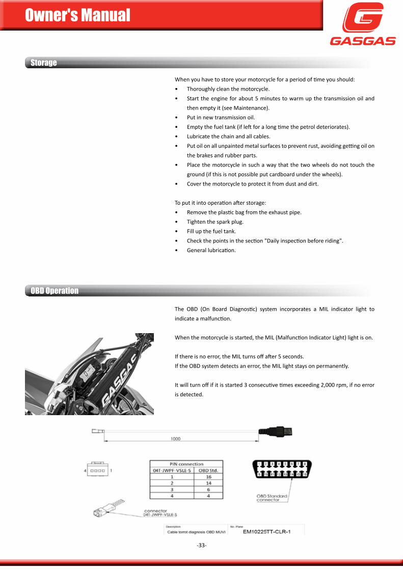
When you have to store your motorcycle for a period of time you should:• Thoroughly clean the motorcycle.• start the engine for about 5 minutes to warm up the transmission oil and
then empty it (see maintenance).• put in new transmission oil.• Empty the fuel tank (if left for a long time the petrol deteriorates).• Lubricate the chain and all cables.• put oil on all unpainted metal surfaces to prevent rust, avoiding getting oil on
the brakes and rubber parts.• place the motorcycle in such a way that the two wheels do not touch the
ground (if this is not possible put cardboard under the wheels).• cover the motorcycle to protect it from dust and dirt.
To put it into operation after storage:• Remove the plastic bag from the exhaust pipe.• Tighten the spark plug.• fill up the fuel tank.• check the points in the section "daily inspection before riding".• general lubrication.
Storage
OBD Operation
The oBd (on Board diagnostic) system incorporates a miL indicator light to indicate a malfunction.
When the motorcycle is started, the miL (malfunction indicator Light) light is on.
if there is no error, the miL turns off after 5 seconds. if the oBd system detects an error, the miL light stays on permanently.
it will turn off if it is started 3 consecutive times exceeding 2,000 rpm, if no error is detected.
Owner's Manual
-34-
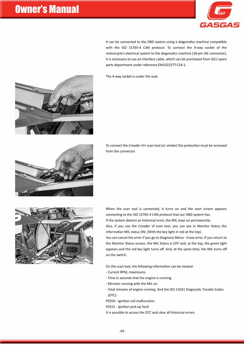
it can be connected to the oBd system using a diagnostics machine compatible with the iso 15765-4 can protocol. To connect the 4-way socket of the motorcycle’s electrical system to the diagnostics machine (18-pin JaE connector), it is necessary to use an interface cable, which can be purchased from gg’s spare parts department under reference Em10225TT-cLR-1.
The 4-way socket is under the seat.
To connect the Creader VI+ scan tool (or similar) the protection must be removed from the connector.
When the scan tool is connected, it turns on and the start screen appears connecting to the iso 15765-4 can protocol that our oBd system has. if the system detects an historical error, the miL stays on permanently. also, if you use the Creader VI scan tool, you can see in monitor status the information miL status on. (With the key light in red at the top). you can cancel the error if you go to diagnosis menu - Erase error. if you return to the monitor status screen, the miL status is off and, at the top, the green light appears and the red key light turns off. and, at the same time, the miL turns off on the switch.
on the scan tool, the following information can be viewed:- current Rpm, maximums.- Time in seconds that the engine is running.- minutes running with the miL on.- Total minutes of engine running. and the iso 15031 diagnostic Trouble codes
(dTc):p0350 - ignition coil malfunction.p0315 - ignition pick-up faultit is possible to access the dTc and clear all historical errors.
Owner's Manual
-35-
MaintenanCe
Owner's Manual
-36-
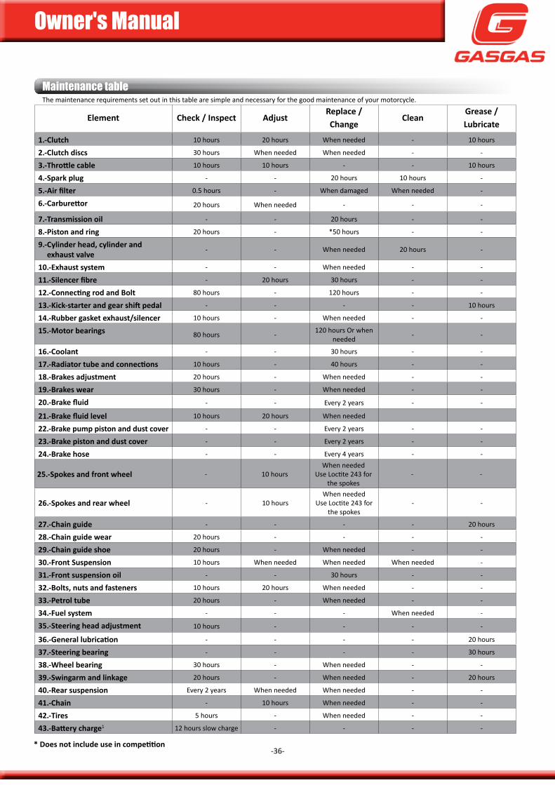
Maintenance tableThe maintenance requirements set out in this table are simple and necessary for the good maintenance of your motorcycle.
element check / inspect adjustreplace / change
cleanGrease / lubricate
1.-clutch 10 hours 20 hours when needed - 10 hours
2.-clutch discs 30 hours when needed when needed - -
3.-Throttle cable 10 hours 10 hours - - 10 hours
4.-spark plug - - 20 hours 10 hours -
5.-Air filter 0.5 hours - When damaged when needed -
6.-Carburettor 20 hours when needed - - -
7.-transmission oil - - 20 hours - -
8.-piston and ring 20 hours - *50 hours - -
9.- cylinder head, cylinder and exhaust valve
- - when needed 20 hours -
10.-exhaust system - - when needed - -
11.-Silencer fibre - 20 hours 30 hours - -
12.-Connecting rod and Bolt 80 hours - 120 hours - -
13.- Kick-starter and gear shift pedal - - - - 10 hours
14.- rubber gasket exhaust/silencer 10 hours - when needed - -
15.-motor bearings 80 hours - 120 hours or when needed - -
16.-coolant - - 30 hours - -
17.- Radiator tube and connections 10 hours - 40 hours - -
18.-brakes adjustment 20 hours - when needed - -
19.-brakes wear 30 hours - when needed - -
20.-Brake fluid - - Every 2 years - -
21.-Brake fluid level 10 hours 20 hours when needed
22.- brake pump piston and dust cover - - Every 2 years - -
23.-brake piston and dust cover - - Every 2 years - -
24.-brake hose - - Every 4 years - -
25.-spokes and front wheel - 10 hourswhen needed
use Loctite 243 for the spokes
- -
26.-spokes and rear wheel - 10 hourswhen needed
use Loctite 243 for the spokes
- -
27.-chain guide - - - - 20 hours
28.-chain guide wear 20 hours - - - -
29.-chain guide shoe 20 hours - when needed - -
30.-front suspension 10 hours when needed when needed when needed -
31.-front suspension oil - - 30 hours - -
32.-bolts, nuts and fasteners 10 hours 20 hours when needed - -
33.-petrol tube 20 hours - when needed - -
34.-fuel system - - - when needed -
35.-steering head adjustment 10 hours - - - -
36.-General lubrication - - - - 20 hours
37.-steering bearing - - - - 30 hours
38.-Wheel bearing 30 hours - when needed - -
39.-swingarm and linkage 20 hours - when needed - 20 hours
40.-rear suspension Every 2 years when needed when needed - -
41.-chain - 10 hours when needed - -
42.-tires 5 hours - when needed - -
43.-Battery charge1 12 hours slow charge - - - -
* Does not include use in competition
Owner's Manual
-37-
Maintenance
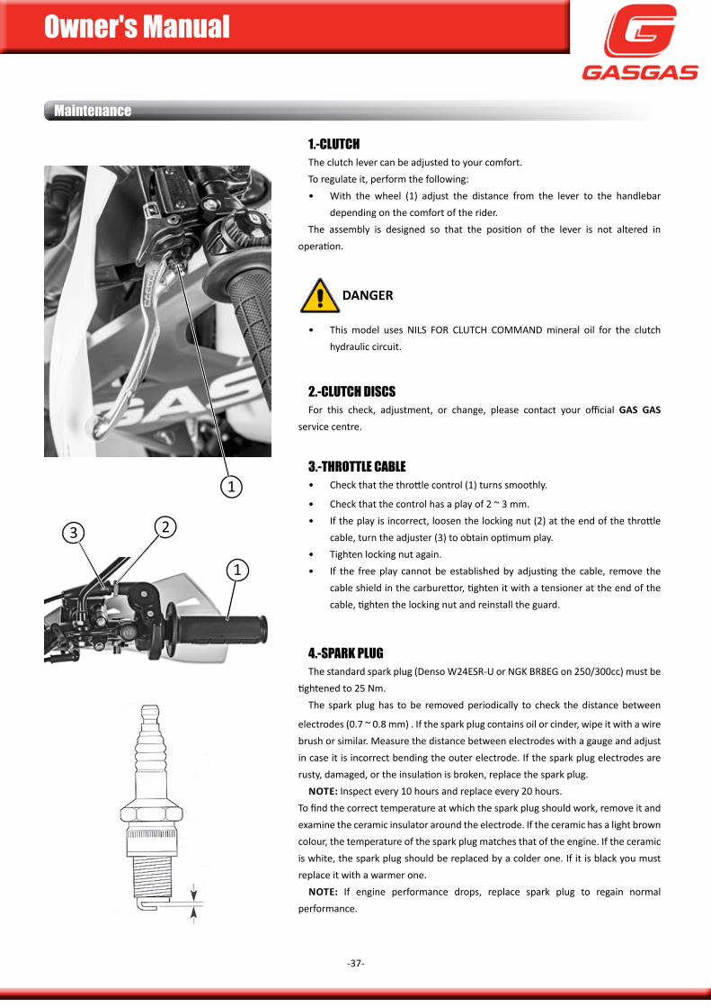
1.-ClutCHThe clutch lever can be adjusted to your comfort.To regulate it, perform the following:• With the wheel (1) adjust the distance from the lever to the handlebar
depending on the comfort of the rider. The assembly is designed so that the position of the lever is not altered in
operation.
DanGer
• This model uses niLs foR cLuTcH command mineral oil for the clutch hydraulic circuit.
2.-ClutCH DiSCSfor this check, adjustment, or change, please contact your official Gas Gas
service centre.
3.-tHrOttle CaBle• check that the throttle control (1) turns smoothly.
• check that the control has a play of 2 ~ 3 mm. • if the play is incorrect, loosen the locking nut (2) at the end of the throttle
cable, turn the adjuster (3) to obtain optimum play.• Tighten locking nut again.• if the free play cannot be established by adjusting the cable, remove the
cable shield in the carburettor, tighten it with a tensioner at the end of the cable, tighten the locking nut and reinstall the guard.
4.-SPark PluGThe standard spark plug (denso W24EsR-u or ngk BR8Eg on 250/300cc) must be
tightened to 25 nm.The spark plug has to be removed periodically to check the distance between
electrodes (0.7 ~ 0.8 mm) . if the spark plug contains oil or cinder, wipe it with a wire brush or similar. measure the distance between electrodes with a gauge and adjust in case it is incorrect bending the outer electrode. if the spark plug electrodes are rusty, damaged, or the insulation is broken, replace the spark plug.
note: inspect every 10 hours and replace every 20 hours. To find the correct temperature at which the spark plug should work, remove it and examine the ceramic insulator around the electrode. if the ceramic has a light brown colour, the temperature of the spark plug matches that of the engine. if the ceramic is white, the spark plug should be replaced by a colder one. if it is black you must replace it with a warmer one.
note: if engine performance drops, replace spark plug to regain normal performance.
1
23
1
Owner's Manual
-38-
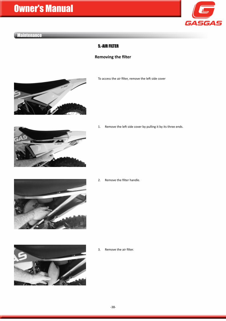
5.-air filter
Removing the filter
To access the air filter, remove the left side cover
1. Remove the left side cover by pulling it by its three ends.
2. Remove the filter handle.
3. Remove the air filter.
Maintenance
Owner's Manual
-39-
Maintenance
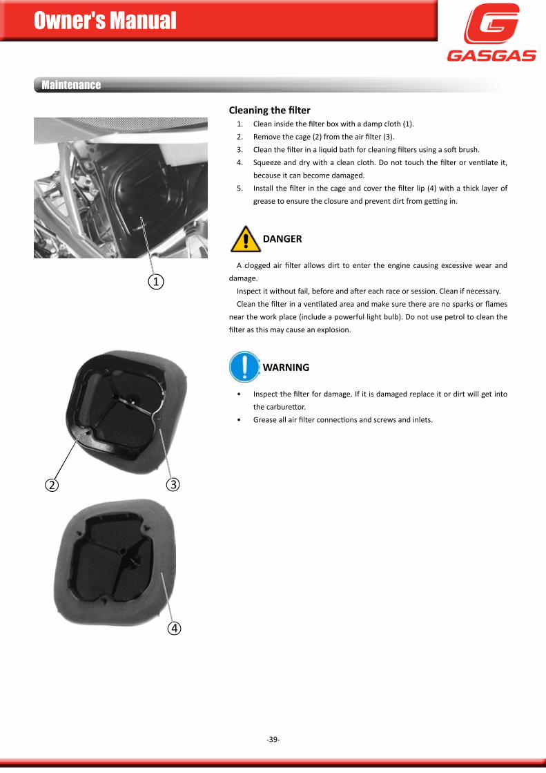
Cleaning the filter1. clean inside the filter box with a damp cloth (1).2. Remove the cage (2) from the air filter (3).3. clean the filter in a liquid bath for cleaning filters using a soft brush.4. squeeze and dry with a clean cloth. do not touch the filter or ventilate it,
because it can become damaged.5. install the filter in the cage and cover the filter lip (4) with a thick layer of
grease to ensure the closure and prevent dirt from getting in.
DanGer a clogged air filter allows dirt to enter the engine causing excessive wear and
damage.inspect it without fail, before and after each race or session. clean if necessary.clean the filter in a ventilated area and make sure there are no sparks or flames
near the work place (include a powerful light bulb). do not use petrol to clean the filter as this may cause an explosion.
WarninG
• inspect the filter for damage. if it is damaged replace it or dirt will get into the carburettor.
• grease all air filter connections and screws and inlets.
2 3
4
1
Owner's Manual
-40-
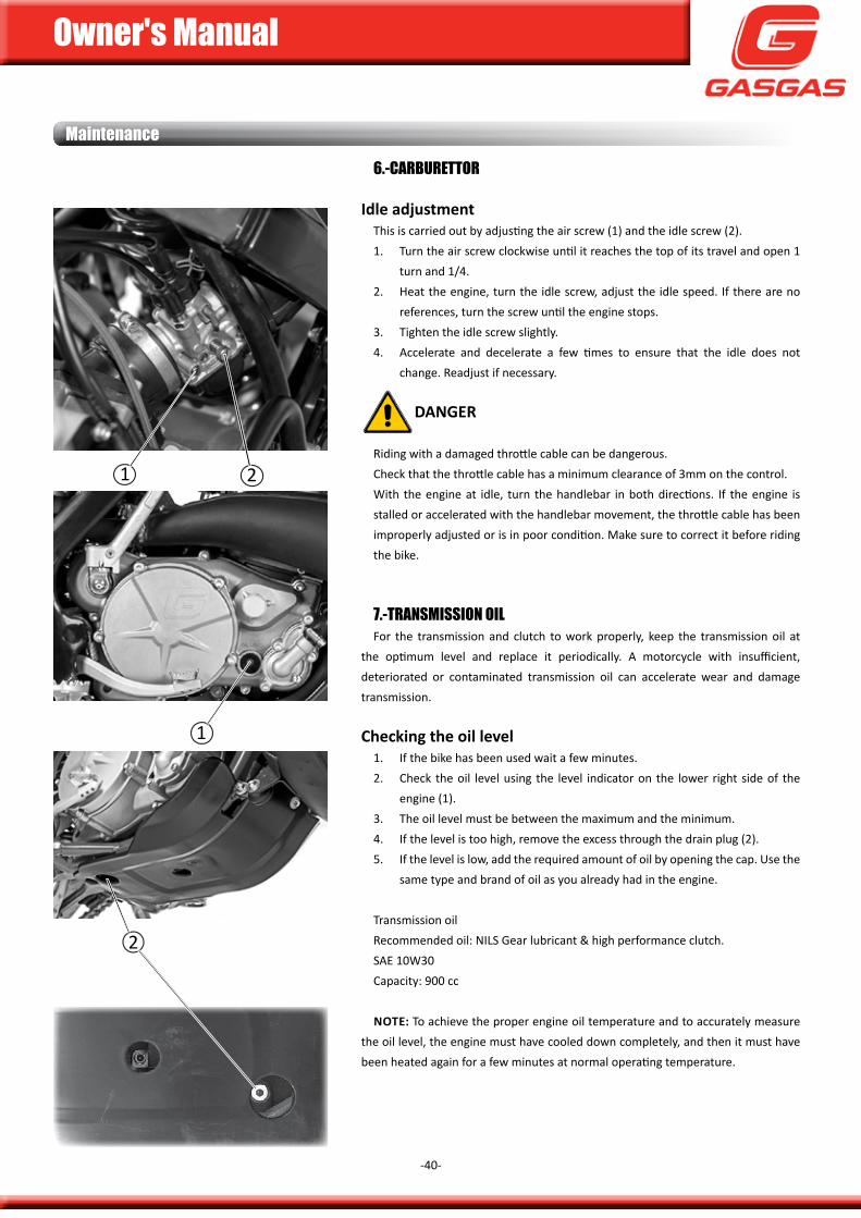
6.-CarBurettOr
idle adjustmentThis is carried out by adjusting the air screw (1) and the idle screw (2).1. Turn the air screw clockwise until it reaches the top of its travel and open 1
turn and 1/4.2. Heat the engine, turn the idle screw, adjust the idle speed. if there are no
references, turn the screw until the engine stops.3. Tighten the idle screw slightly.4. accelerate and decelerate a few times to ensure that the idle does not
change. Readjust if necessary.
DanGer
Riding with a damaged throttle cable can be dangerous.check that the throttle cable has a minimum clearance of 3mm on the control. With the engine at idle, turn the handlebar in both directions. if the engine is stalled or accelerated with the handlebar movement, the throttle cable has been improperly adjusted or is in poor condition. make sure to correct it before riding the bike.
7.-tranSMiSSiOn Oilfor the transmission and clutch to work properly, keep the transmission oil at
the optimum level and replace it periodically. a motorcycle with insufficient, deteriorated or contaminated transmission oil can accelerate wear and damage transmission.
checking the oil level1. if the bike has been used wait a few minutes.2. check the oil level using the level indicator on the lower right side of the
engine (1).3. The oil level must be between the maximum and the minimum.4. if the level is too high, remove the excess through the drain plug (2).5. if the level is low, add the required amount of oil by opening the cap. use the
same type and brand of oil as you already had in the engine.
Transmission oilRecommended oil: niLs gear lubricant & high performance clutch.SAe 10w30capacity: 900 cc
note: To achieve the proper engine oil temperature and to accurately measure the oil level, the engine must have cooled down completely, and then it must have been heated again for a few minutes at normal operating temperature.
Maintenance
1 2
1
2
Owner's Manual
-41-
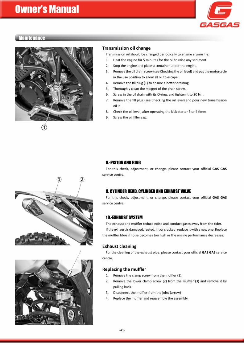
transmission oil changeTransmission oil should be changed periodically to ensure engine life.1. Heat the engine for 5 minutes for the oil to raise any sediment.2. stop the engine and place a container under the engine.3. Remove the oil drain screw (see checking the oil level) and put the motorcycle
in the use position to allow all oil to escape.4. Remove the fill plug (1) to ensure a better draining.5. Thoroughly clean the magnet of the drain screw. 6. screw in the oil drain with its o-ring, and tighten it to 20 nm.7. Remove the fill plug (see checking the oil level) and pour new transmission
oil in. 8. check the oil level, after operating the kick-starter 3 or 4 times.9. screw the oil filler cap.
Maintenance
8.-PiStOn anD rinGfor this check, adjustment, or change, please contact your official Gas Gas
service centre.
9. CylinDer HeaD, CylinDer anD exHauSt valvefor this check, adjustment, or change, please contact your official Gas Gas
service centre.
10.-exHauSt SySteMThe exhaust and muffler reduce noise and conduct gases away from the rider.if the exhaust is damaged, rusted, hit or cracked, replace it with a new one. Replace
the muffler fibre if noise becomes too high or the engine performance decreases.
exhaust cleaningfor the cleaning of the exhaust pipe, please contact your official Gas Gas service
centre.
Replacing the muffler1. Remove the clamp screw from the muffler (1).2. Remove the lower clamp screw (2) from the muffler (3) and remove it by
pulling back.3. disconnect the muffler from the joint (arrow)4. Replace the muffler and reassemble the assembly.
1
1 2
Owner's Manual
-42-
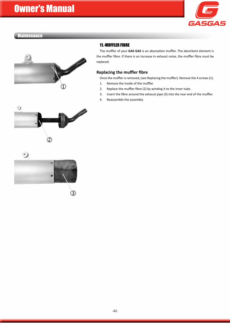
11.-Muffler fiBreThe muffler of your Gas Gas is an absorption muffler. The absorbent element is
the muffler fibre. if there is an increase in exhaust noise, the muffler fibre must be replaced.
Replacing the muffler fibreonce the muffler is removed, (see Replacing the muffler). Remove the 4 screws (1).1. Remove the inside of the muffler.2. Replace the muffler fibre (2) by winding it to the inner tube.3. insert the fibre around the exhaust pipe (3) into the rear end of the muffler.4. Reassemble the assembly.
Maintenance
1
2
3
Owner's Manual
-43-
12.-COnneCtinG rOD anD BearinGSfor this check, adjustment, or change, please contact your official Gas Gas
service centre.
13.-kiCk-Starter anD Gear SHift PeDalLubricate the moving and articulated parts with oil or grease, excessive lubrication
can cause your boots to slip on the pedals.
Maintenance
14.-ruBBer GaSket exHauSt/SilenCerfor this check, adjustment, or change, please contact your official Gas Gas
service centre.
15.-MOtOr BearinGSfor this check, adjustment, or change, please contact your official Gas Gas
service centre.
16.-COOlantThe coolant absorbs excessive heat from the engine and transfers it to the air
through the radiator. if the fluid level drops, the engine overheats and can severely damage it. check your fluid level every day before riding your Gas Gas.
To protect the aluminium parts of the cooling system (engine and radiator) from rust and corrosion, use chemical inhibitors in the essence of coolant. if an anti-corrosive liquid were not used, after a while the radiator would rust. This would obstruct the cooling tubes.
note: initially, a permanent-type antifreeze is used at the factory. it is green, contains 30% ethylene glycol and has a freezing point of -18ºc.
DanGer
chemical liquids are harmful to the human body. follow the manufacturer's instructions.
WarninG
use of incorrect liquid solutions can cause damage to the engine and cooling system.
use coolant with anti-corrosive specific for aluminium engines and radiators according to the manufacturer's instructions.
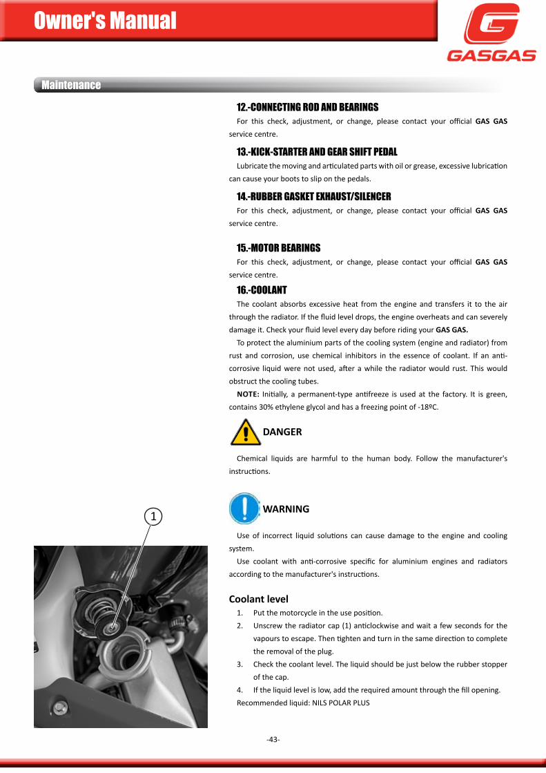
coolant level1. put the motorcycle in the use position.2. unscrew the radiator cap (1) anticlockwise and wait a few seconds for the
vapours to escape. Then tighten and turn in the same direction to complete the removal of the plug.
3. check the coolant level. The liquid should be just below the rubber stopper of the cap.
4. if the liquid level is low, add the required amount through the fill opening.Recommended liquid: niLs poLaR pLus
1
Owner's Manual
-44-
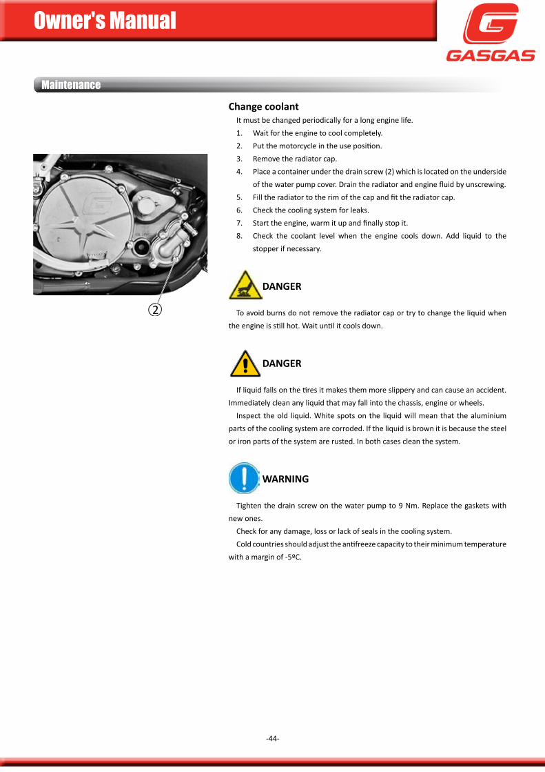
change coolantit must be changed periodically for a long engine life.1. Wait for the engine to cool completely.2. put the motorcycle in the use position.3. Remove the radiator cap.4. place a container under the drain screw (2) which is located on the underside
of the water pump cover. drain the radiator and engine fluid by unscrewing.5. fill the radiator to the rim of the cap and fit the radiator cap.6. check the cooling system for leaks.7. start the engine, warm it up and finally stop it.8. check the coolant level when the engine cools down. add liquid to the
stopper if necessary.
DanGer
To avoid burns do not remove the radiator cap or try to change the liquid when the engine is still hot. Wait until it cools down.
DanGer
if liquid falls on the tires it makes them more slippery and can cause an accident. immediately clean any liquid that may fall into the chassis, engine or wheels.
inspect the old liquid. White spots on the liquid will mean that the aluminium parts of the cooling system are corroded. if the liquid is brown it is because the steel or iron parts of the system are rusted. in both cases clean the system.
WarninG
Tighten the drain screw on the water pump to 9 nm. Replace the gaskets with new ones.
check for any damage, loss or lack of seals in the cooling system. cold countries should adjust the antifreeze capacity to their minimum temperature
with a margin of -5ºc.
Maintenance
2
Owner's Manual
-45-
Maintenance
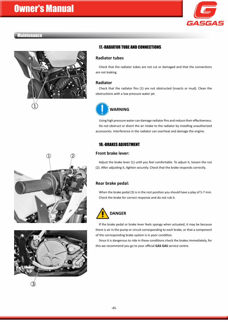
17.-raDiatOr tuBe anD COnneCtiOnS
radiator tubes
check that the radiator tubes are not cut or damaged and that the connections are not leaking.
radiatorcheck that the radiator fins (1) are not obstructed (insects or mud). clean the
obstructions with a low pressure water jet.
WarninG
using high pressure water can damage radiator fins and reduce their effectiveness.do not obstruct or divert the air intake to the radiator by installing unauthorized
accessories. interference in the radiator can overheat and damage the engine.
18.-BrakeS aDjuStMent
front brake lever:
adjust the brake lever (1) until you feel comfortable. To adjust it, loosen the nut (2). after adjusting it, tighten securely. check that the brake responds correctly.
rear brake pedal:
When the brake pedal (3) is in the rest position you should have a play of 5-7 mm. check the brake for correct response and do not rub it.
DanGer
if the brake pedal or brake lever feels spongy when actuated, it may be because there is air in the pump or circuit corresponding to each brake, or that a component of the corresponding brake system is in poor condition.
since it is dangerous to ride in these conditions check the brakes immediately, for this we recommend you go to your official Gas Gas service centre.
1
3
1 2
Owner's Manual
-46-
19.-BrakeS wearif the thickness of any of the brake pads on the front or rear disc is less than 1mm,
a complete change of the affected pad set must be carried out.
DanGer
check that the thickness of the discs is at least 3 mm on the front and 3.5 mm on the rear.
WarninG
for this change we recommend that you go to your official Gas Gas service centre who, in addition, will check the possible wear of your brake discs.
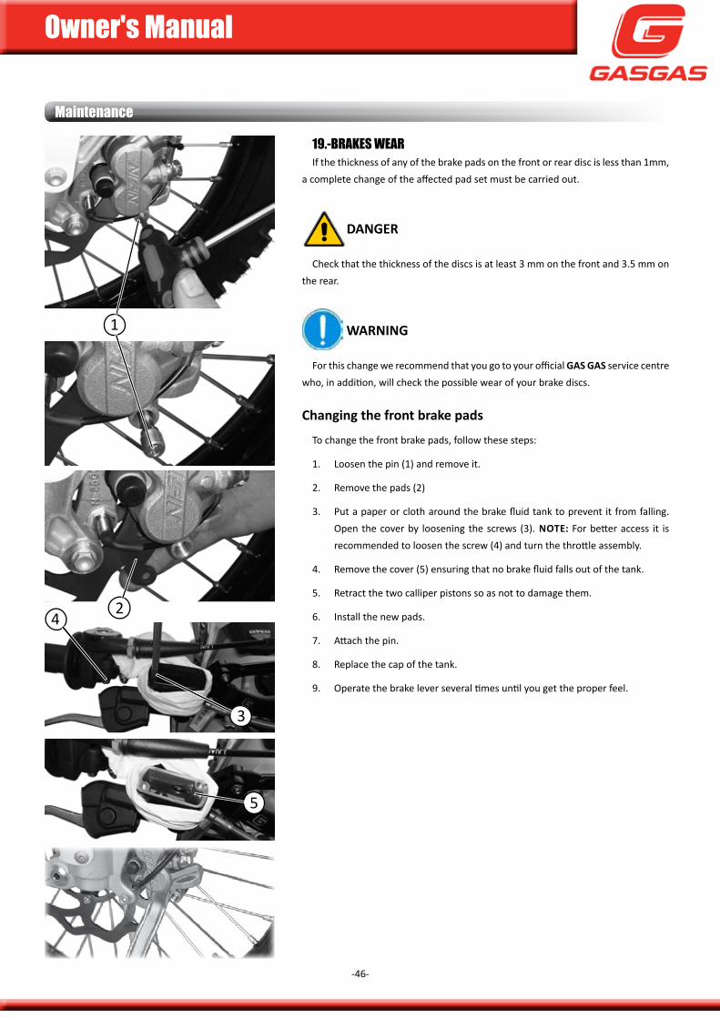
changing the front brake pads
To change the front brake pads, follow these steps:
1. Loosen the pin (1) and remove it.
2. Remove the pads (2)
3. put a paper or cloth around the brake fluid tank to prevent it from falling. open the cover by loosening the screws (3). note: for better access it is recommended to loosen the screw (4) and turn the throttle assembly.
4. Remove the cover (5) ensuring that no brake fluid falls out of the tank.
5. Retract the two calliper pistons so as not to damage them.
6. install the new pads.
7. attach the pin.
8. Replace the cap of the tank.
9. operate the brake lever several times until you get the proper feel.
Maintenance
1
2
3
4
5
Owner's Manual
-47-
Maintenance
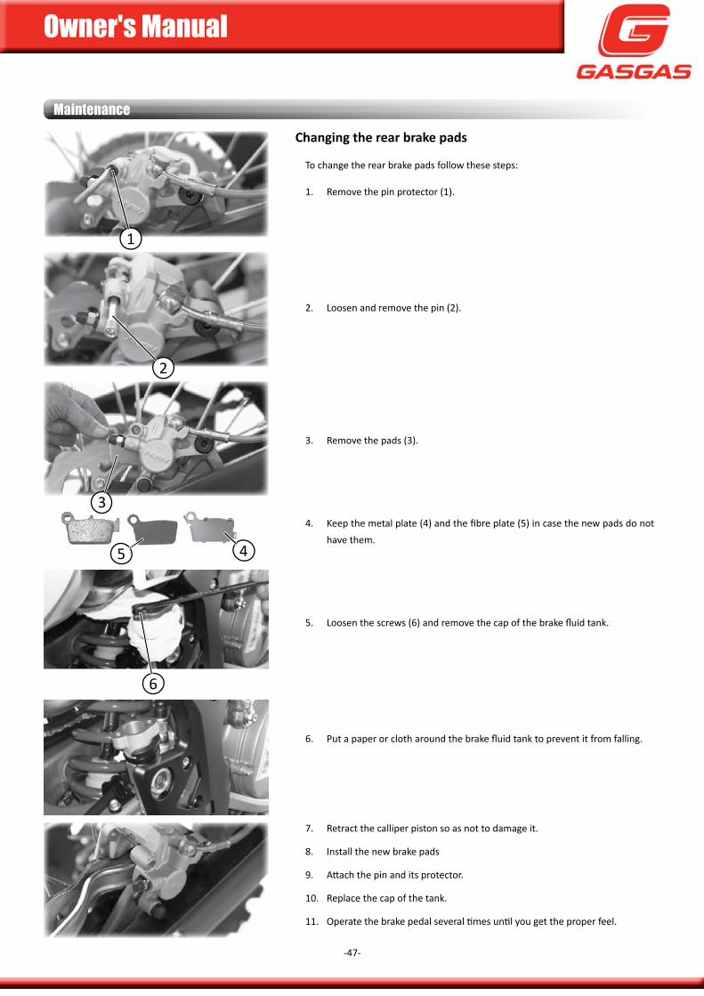
changing the rear brake pads
To change the rear brake pads follow these steps:
1. Remove the pin protector (1).
2. Loosen and remove the pin (2).
3. Remove the pads (3).
4. keep the metal plate (4) and the fibre plate (5) in case the new pads do not have them.
5. Loosen the screws (6) and remove the cap of the brake fluid tank.
6. put a paper or cloth around the brake fluid tank to prevent it from falling.
7. Retract the calliper piston so as not to damage it.
8. install the new brake pads
9. attach the pin and its protector.
10. Replace the cap of the tank.
11. operate the brake pedal several times until you get the proper feel.
1
2
3
5 4
6
Owner's Manual
-48-
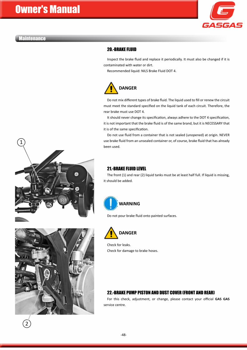
21.-Brake fluiD levelThe front (1) and rear (2) liquid tanks must be at least half full. if liquid is missing,
it should be added.
WarninG
do not pour brake fluid onto painted surfaces.
DanGer
check for leaks.check for damage to brake hoses.
20.-Brake fluiD
inspect the brake fluid and replace it periodically. it must also be changed if it is contaminated with water or dirt.
Recommended liquid: niLs Brake fluid doT 4.
DanGer
do not mix different types of brake fluid. The liquid used to fill or renew the circuit must meet the standard specified on the liquid tank of each circuit. Therefore, the rear brake must use doT 4.
it should never change its specification, always adhere to the doT 4 specification, it is not important that the brake fluid is of the same brand, but it is nEcEssaRy that it is of the same specification.
do not use fluid from a container that is not sealed (unopened) at origin. nEVER use brake fluid from an unsealed container or, of course, brake fluid that has already been used.
22.-Brake PuMP PiStOn anD DuSt COver (frOnt anD rear)for this check, adjustment, or change, please contact your official Gas Gas
service centre.
Maintenance
1
2
Owner's Manual
-49-
Maintenance
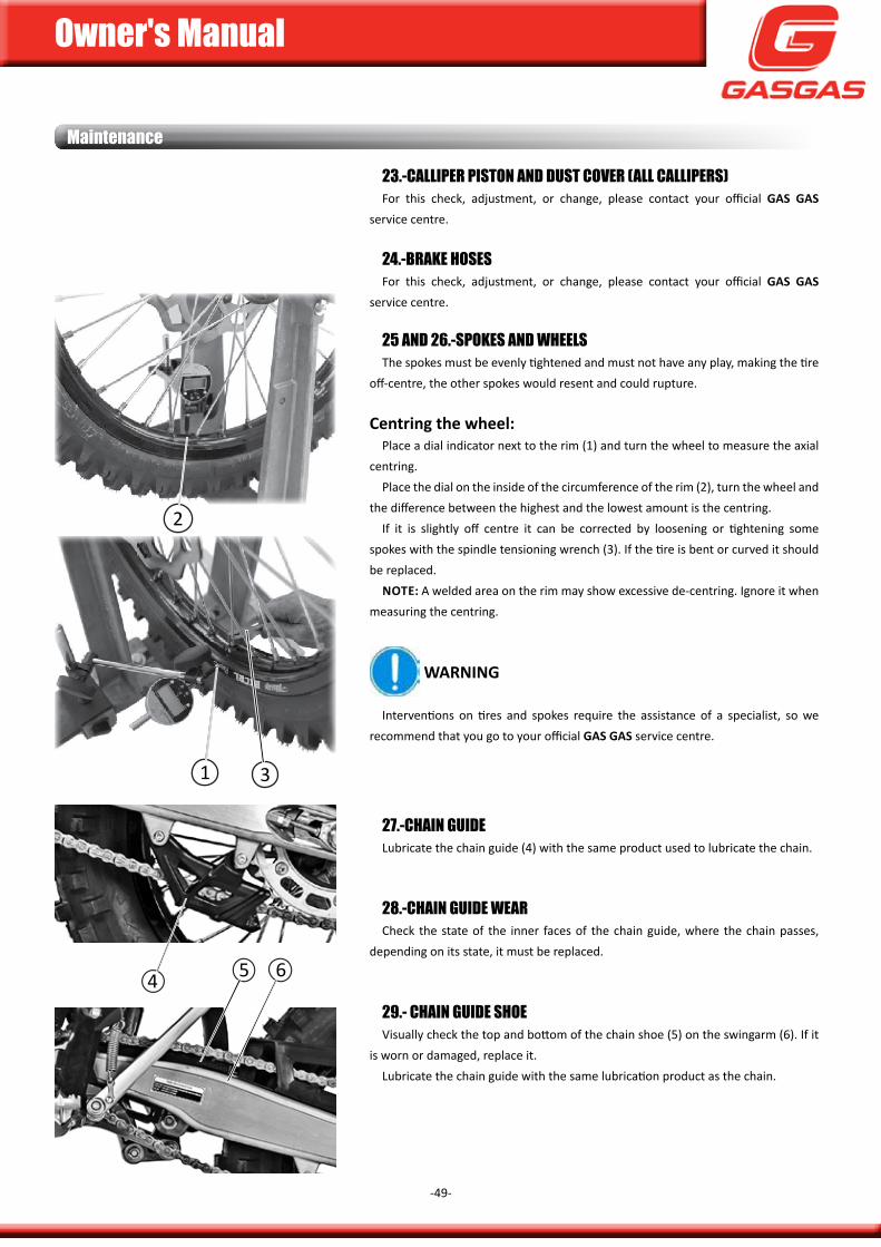
25 anD 26.-SPOkeS anD wHeelSThe spokes must be evenly tightened and must not have any play, making the tire
off-centre, the other spokes would resent and could rupture.
centring the wheel:place a dial indicator next to the rim (1) and turn the wheel to measure the axial
centring.place the dial on the inside of the circumference of the rim (2), turn the wheel and
the difference between the highest and the lowest amount is the centring.if it is slightly off centre it can be corrected by loosening or tightening some
spokes with the spindle tensioning wrench (3). if the tire is bent or curved it should be replaced.
note: a welded area on the rim may show excessive de-centring. ignore it when measuring the centring.
WarninG
interventions on tires and spokes require the assistance of a specialist, so we recommend that you go to your official Gas Gas service centre.
27.-CHain GuiDeLubricate the chain guide (4) with the same product used to lubricate the chain.
28.-CHain GuiDe wearcheck the state of the inner faces of the chain guide, where the chain passes,
depending on its state, it must be replaced.
29.- CHain GuiDe SHOeVisually check the top and bottom of the chain shoe (5) on the swingarm (6). if it
is worn or damaged, replace it.Lubricate the chain guide with the same lubrication product as the chain.
23.-CalliPer PiStOn anD DuSt COver (all CalliPerS)for this check, adjustment, or change, please contact your official Gas Gas
service centre.
24.-Brake HOSeSfor this check, adjustment, or change, please contact your official Gas Gas
service centre.
1
2
3
4 5 6
Owner's Manual
-50-
Maintenance
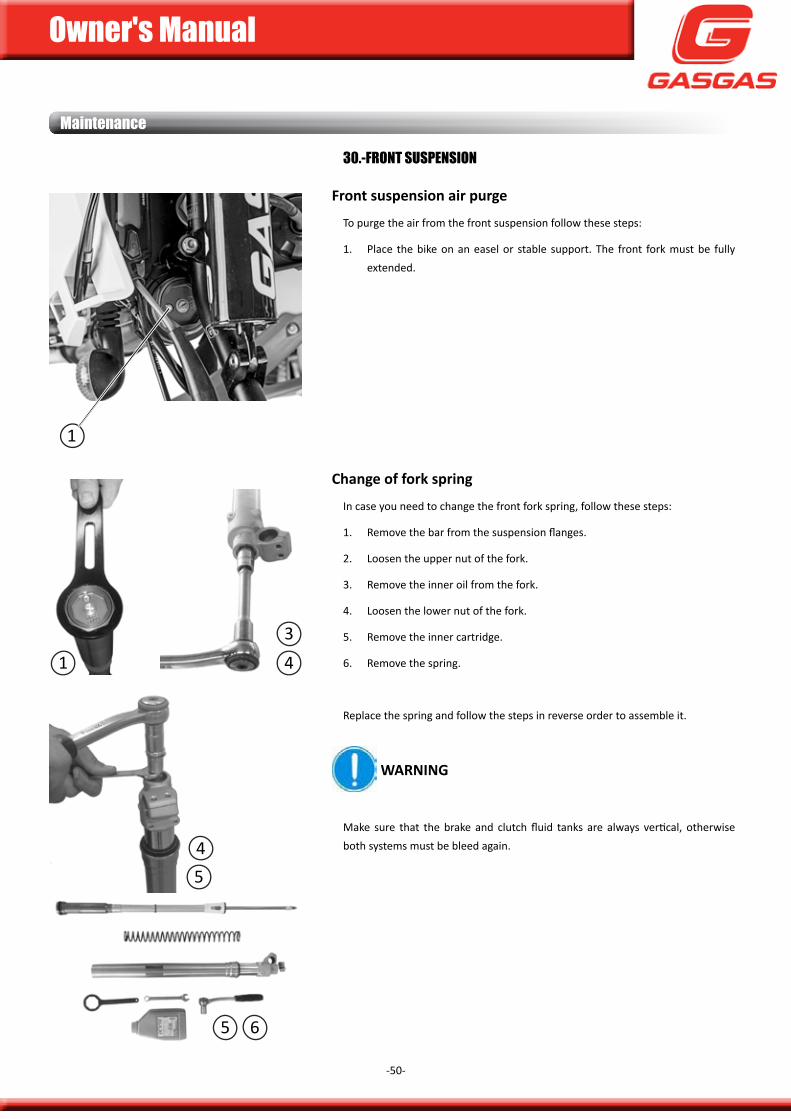
30.-frOnt SuSPenSiOn
front suspension air purge
To purge the air from the front suspension follow these steps:
1. place the bike on an easel or stable support. The front fork must be fully extended.
change of fork spring
in case you need to change the front fork spring, follow these steps:
1. Remove the bar from the suspension flanges.
2. Loosen the upper nut of the fork.
3. Remove the inner oil from the fork.
4. Loosen the lower nut of the fork.
5. Remove the inner cartridge.
6. Remove the spring.
Replace the spring and follow the steps in reverse order to assemble it.
WarninG
make sure that the brake and clutch fluid tanks are always vertical, otherwise both systems must be bleed again.
1
1
4
4
5 6
3
5
Owner's Manual
-51-
Maintenance
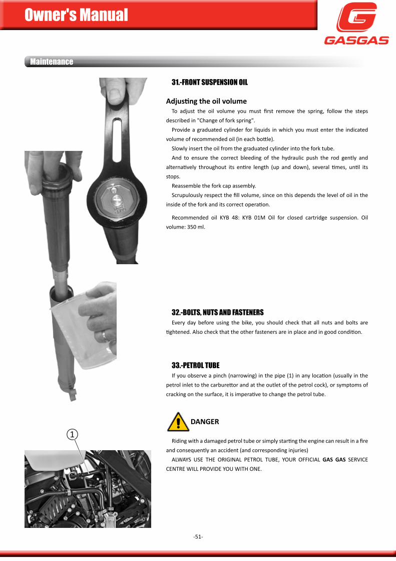
31.-frOnt SuSPenSiOn Oil
Adjusting the oil volumeTo adjust the oil volume you must first remove the spring, follow the steps
described in "change of fork spring".provide a graduated cylinder for liquids in which you must enter the indicated
volume of recommended oil (in each bottle).slowly insert the oil from the graduated cylinder into the fork tube. and to ensure the correct bleeding of the hydraulic push the rod gently and
alternatively throughout its entire length (up and down), several times, until its stops.
Reassemble the fork cap assembly.scrupulously respect the fill volume, since on this depends the level of oil in the
inside of the fork and its correct operation.
Recommended oil kyB 48: kyB 01m oil for closed cartridge suspension. oil volume: 350 ml.
32.-BOltS, nutS anD faStenerSEvery day before using the bike, you should check that all nuts and bolts are
tightened. also check that the other fasteners are in place and in good condition.
33.-PetrOl tuBeif you observe a pinch (narrowing) in the pipe (1) in any location (usually in the
petrol inlet to the carburettor and at the outlet of the petrol cock), or symptoms of cracking on the surface, it is imperative to change the petrol tube.
DanGer
Riding with a damaged petrol tube or simply starting the engine can result in a fire and consequently an accident (and corresponding injuries)
aLWays usE THE oRiginaL pETRoL TuBE, youR officiaL Gas Gas SerVIce cEnTRE WiLL pRoVidE you WiTH onE.
1
Owner's Manual
-52-
Maintenance
34.-fuel SySteMcheck the status of: The rubber of the tank cap, the tank cap, the tank breather
tube and the tank.
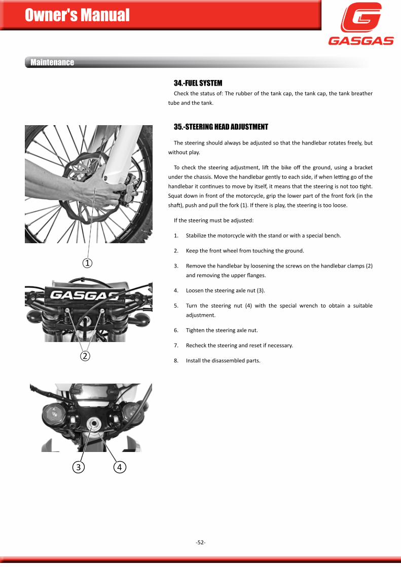
35.-SteerinG HeaD aDjuStMent
The steering should always be adjusted so that the handlebar rotates freely, but without play.
To check the steering adjustment, lift the bike off the ground, using a bracket under the chassis. move the handlebar gently to each side, if when letting go of the handlebar it continues to move by itself, it means that the steering is not too tight. squat down in front of the motorcycle, grip the lower part of the front fork (in the shaft), push and pull the fork (1). if there is play, the steering is too loose.
if the steering must be adjusted:
1. stabilize the motorcycle with the stand or with a special bench.
2. keep the front wheel from touching the ground.
3. Remove the handlebar by loosening the screws on the handlebar clamps (2) and removing the upper flanges.
4. Loosen the steering axle nut (3).
5. Turn the steering nut (4) with the special wrench to obtain a suitable adjustment.
6. Tighten the steering axle nut.
7. Recheck the steering and reset if necessary.
8. install the disassembled parts.2
1
3 4
Owner's Manual
-53-
Maintenance
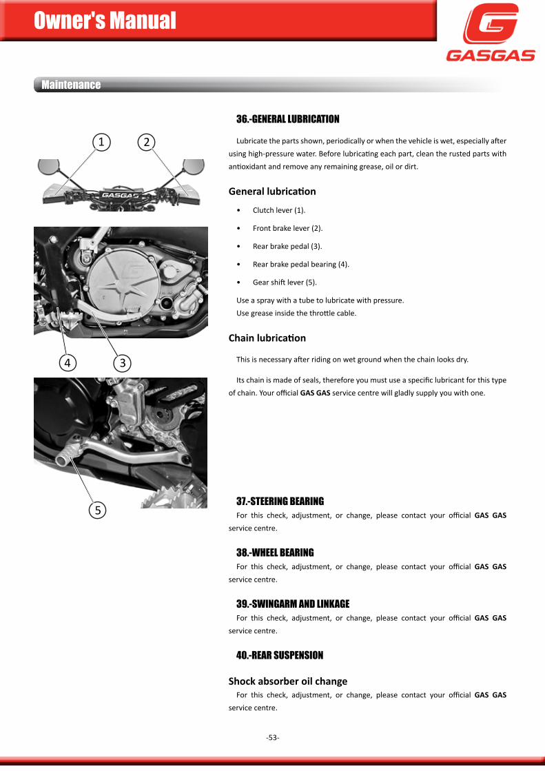
36.-General luBriCatiOn
Lubricate the parts shown, periodically or when the vehicle is wet, especially after using high-pressure water. Before lubricating each part, clean the rusted parts with antioxidant and remove any remaining grease, oil or dirt.
General lubrication
• clutch lever (1).
• front brake lever (2).
• Rear brake pedal (3).
• Rear brake pedal bearing (4).
• gear shift lever (5).
use a spray with a tube to lubricate with pressure.use grease inside the throttle cable.
Chain lubrication
This is necessary after riding on wet ground when the chain looks dry.
its chain is made of seals, therefore you must use a specific lubricant for this type of chain. your official Gas Gas service centre will gladly supply you with one.
37.-SteerinG BearinGfor this check, adjustment, or change, please contact your official Gas Gas
service centre.
38.-wHeel BearinGfor this check, adjustment, or change, please contact your official Gas Gas
service centre.
39.-SwinGarM anD linkaGefor this check, adjustment, or change, please contact your official Gas Gas
service centre.
40.-rear SuSPenSiOn
shock absorber oil changefor this check, adjustment, or change, please contact your official Gas Gas
service centre.
1 2
4 3
5
Owner's Manual
-54-
Maintenance
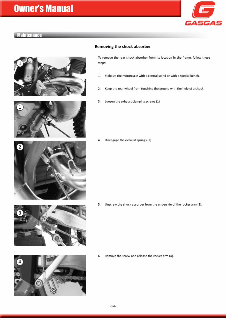
removing the shock absorber
To remove the rear shock absorber from its location in the frame, follow these steps:
1. stabilize the motorcycle with a central stand or with a special bench.
2. keep the rear wheel from touching the ground with the help of a chock.
3. Loosen the exhaust clamping screws (1)
4. disengage the exhaust springs (2)
5. unscrew the shock absorber from the underside of the rocker arm (3).
6. Remove the screw and release the rocker arm (4).
1
1
2
3
4
Owner's Manual
-55-
Maintenance
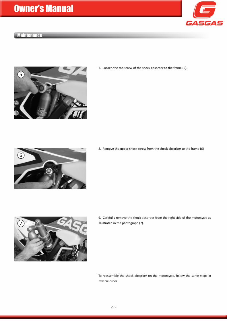
7. Loosen the top screw of the shock absorber to the frame (5).
8. Remove the upper shock screw from the shock absorber to the frame (6)
9. carefully remove the shock absorber from the right side of the motorcycle as illustrated in the photograph (7).
To reassemble the shock absorber on the motorcycle, follow the same steps in reverse order.
5
6
7
Owner's Manual
-56-
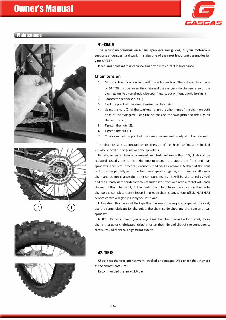
41.-CHainThe secondary transmission (chain, sprockets and guides) of your motorcycle
supports undergoes hard work. it is also one of the most important assemblies for your safETy.
it requires constant maintenance and obviously, correct maintenance.
chain tension1. motorcycle without load and with the side stand out: There should be a space
of 30 ~ 36 mm. between the chain and the swingarm in the rear area of the chain guide. you can check with your fingers, but without overly forcing it.
2. Loosen the rear axle nut (1).3. find the point of maximum tension on the chain.4. using the nuts (2) of the tensioner, align the alignment of the chain on both
ends of the swingarm using the notches on the swingarm and the lugs on the adjusters.
5. Tighten the nuts (2).6. Tighten the nut (1).7. check again at the point of maximum tension and re-adjust it if necessary.
The chain tension is a constant check. The state of the chain itself must be checked visually, as well as the guide and the sprockets.
usually, when a chain is overused, or stretched more than 2%, it should be replaced. usually this is the right time to change the guide, the front and rear sprockets. This is for practical, economic and safETy reasons. a chain at the limit of its use has partially worn the teeth rear sprocket, guide, etc. if you install a new chain and do not change the other components, its life will be shortened by 40% and the already-deteriorated elements such as the front and rear sprocket will reach the end of their life quickly. in the medium and long term, the economic thing is to change the complete transmission kit at each chain change. your official Gas Gas service centre will gladly supply you with one.
Lubrication: its chain is of the type that has seals, this requires a special lubricant, use the same lubricant for the guide, the chain guide shoe and the front and rear sprocket.
note: We recommend you always have the chain correctly lubricated, those chains that go dry, lubricated, dried, shorten their life and that of the components that surround them to a significant extent.
Maintenance
42.-tireScheck that the tires are not worn, cracked or damaged. also check that they are
at the correct pressure.Recommended pressure: 1.0 bar
12
Owner's Manual
-57-
Maintenance
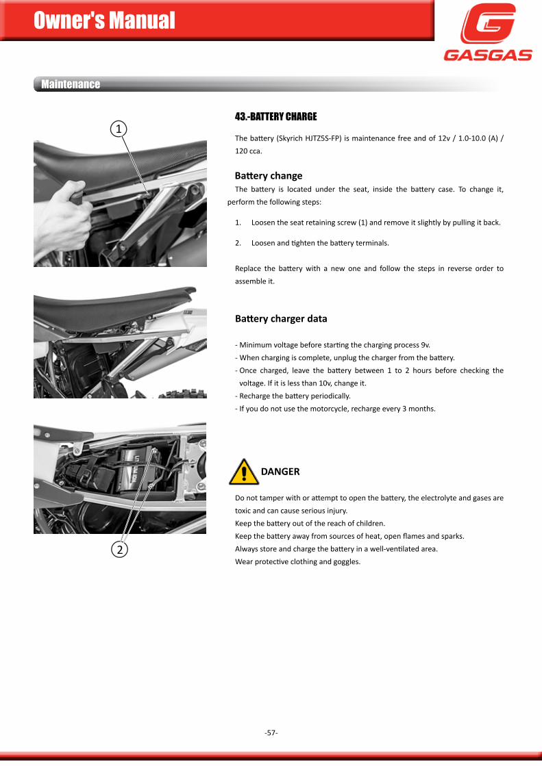
43.-Battery CHarGe
The battery (skyrich HJTZ5s-fp) is maintenance free and of 12v / 1.0-10.0 (a) / 120 cca.
Battery changeThe battery is located under the seat, inside the battery case. To change it,
perform the following steps:
1. Loosen the seat retaining screw (1) and remove it slightly by pulling it back.
2. Loosen and tighten the battery terminals.
Replace the battery with a new one and follow the steps in reverse order to assemble it.
Battery charger data
- minimum voltage before starting the charging process 9v.- When charging is complete, unplug the charger from the battery.- once charged, leave the battery between 1 to 2 hours before checking the
voltage. if it is less than 10v, change it.- Recharge the battery periodically.- if you do not use the motorcycle, recharge every 3 months.
DanGer
do not tamper with or attempt to open the battery, the electrolyte and gases are toxic and can cause serious injury.keep the battery out of the reach of children.keep the battery away from sources of heat, open flames and sparks.always store and charge the battery in a well-ventilated area.Wear protective clothing and goggles.
2
1
Owner's Manual
-58-
This page has been left blank intentionally.
SettinGS
Owner's Manual
-59-
Carburator setting * for xC model
The settings chapter is for a user with high mechanical knowledge and experience.otherwise these adjustments must be carried out by your official Gas Gas service
centre.
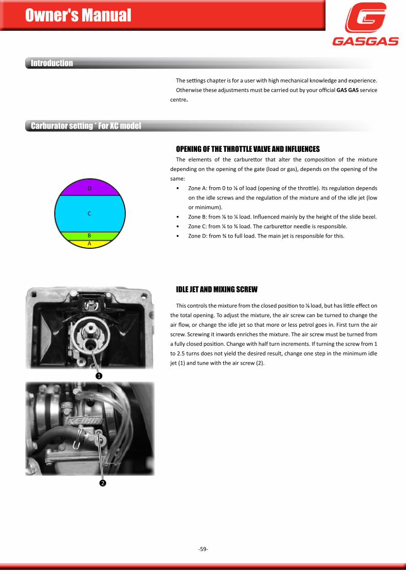
iDle jet anD MixinG SCrew
This controls the mixture from the closed position to ⅛ load, but has little effect on the total opening. To adjust the mixture, the air screw can be turned to change the air flow, or change the idle jet so that more or less petrol goes in. first turn the air screw. screwing it inwards enriches the mixture. The air screw must be turned from a fully closed position. change with half turn increments. if turning the screw from 1 to 2.5 turns does not yield the desired result, change one step in the minimum idle jet (1) and tune with the air screw (2).
1
2
OPeninG Of tHe tHrOttle valve anD influenCeSThe elements of the carburettor that alter the composition of the mixture
depending on the opening of the gate (load or gas), depends on the opening of the same:
• Zone a: from 0 to ⅛ of load (opening of the throttle). its regulation depends on the idle screws and the regulation of the mixture and of the idle jet (low or minimum).
• Zone B: from ⅛ to ¼ load. influenced mainly by the height of the slide bezel.• Zone c: from ¼ to ¾ load. The carburettor needle is responsible. • Zone d: from ¾ to full load. The main jet is responsible for this.
Ab
c
d
introduction
Owner's Manual
-60-
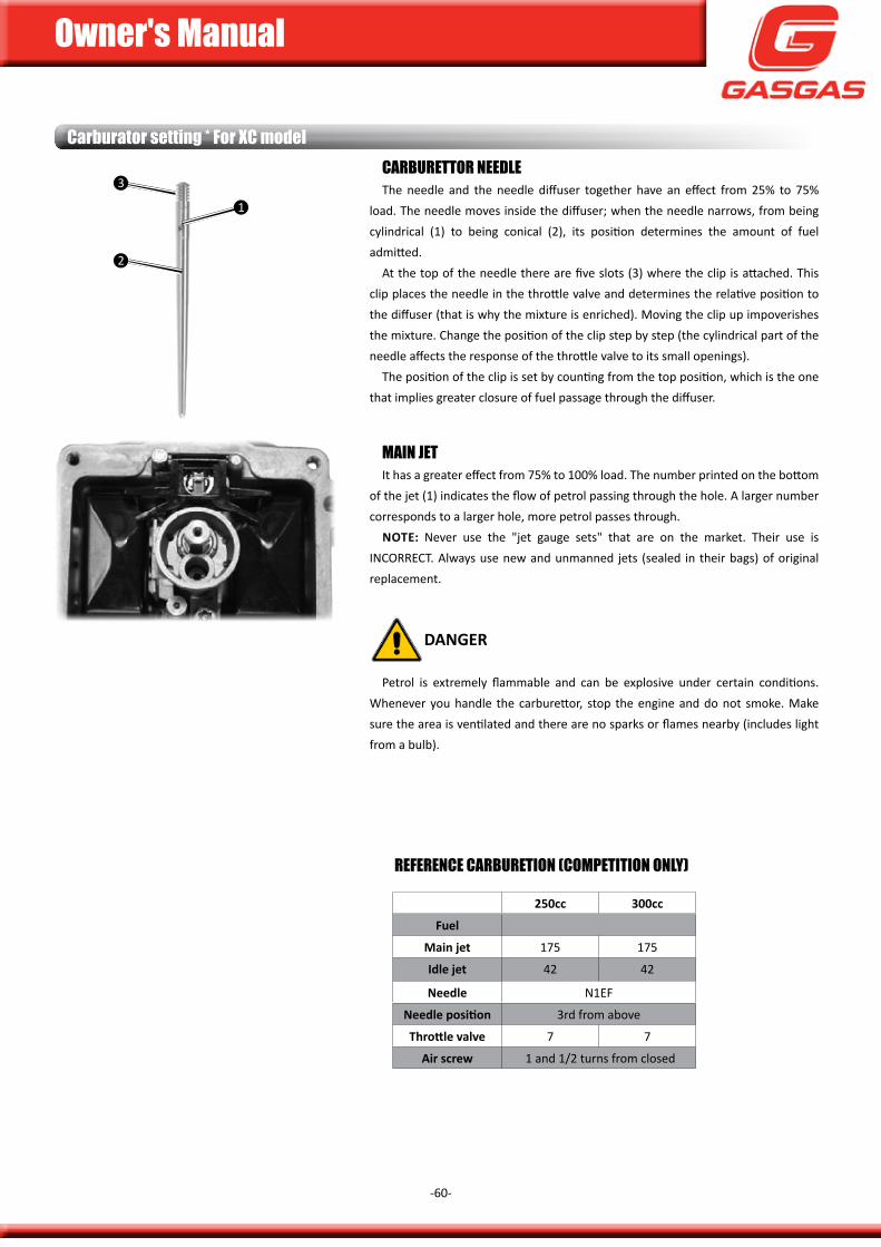
Main jetit has a greater effect from 75% to 100% load. The number printed on the bottom
of the jet (1) indicates the flow of petrol passing through the hole. a larger number corresponds to a larger hole, more petrol passes through.
note: never use the "jet gauge sets" that are on the market. Their use is incoRREcT. always use new and unmanned jets (sealed in their bags) of original replacement.
DanGer
petrol is extremely flammable and can be explosive under certain conditions. Whenever you handle the carburettor, stop the engine and do not smoke. make sure the area is ventilated and there are no sparks or flames nearby (includes light from a bulb).
1
Carburator setting * for xC modelCarBurettOr neeDleThe needle and the needle diffuser together have an effect from 25% to 75%
load. The needle moves inside the diffuser; when the needle narrows, from being cylindrical (1) to being conical (2), its position determines the amount of fuel admitted.
at the top of the needle there are five slots (3) where the clip is attached. This clip places the needle in the throttle valve and determines the relative position to the diffuser (that is why the mixture is enriched). moving the clip up impoverishes the mixture. change the position of the clip step by step (the cylindrical part of the needle affects the response of the throttle valve to its small openings).
The position of the clip is set by counting from the top position, which is the one that implies greater closure of fuel passage through the diffuser.
3
2
1
250cc 300cc
fuel
main jet 175 175
idle jet 42 42
needle n1ef
Needle position 3rd from above
Throttle valve 7 7
air screw 1 and 1/2 turns from closed
referenCe CarBuretiOn (COMPetitiOn Only)
Owner's Manual
-61-
Carburator setting * for xC model
1. find the correction factor to adjust carburizing. example: 1000 m height and temperature of 35°c, correction 0.94.
2. using the correction factor, select the main jet. example: factor 0.94, you must multiply the main jet by this number. main jet = 175 x 0.94 = 165.
3. find your correction factor for the needle and air screw in the table and change the position of the clip and the air screw opening. example: Lift up the needle clip and turn the air screw one turn.
COrreCtiOn faCtOrS 250 / 300CC.(for changes in height or temperature).
Needle position / Air screw openingCorrection factor 1.06 or higher 1.06 ~ 1.02 1.02 ~ 0.98 0.98 ~ 0.94 0.94 or less
Needle position Lower clip 1 position same same same Raise clip 1 position
opening screw free Tighten 1 turn Tighten ½ turn same Loosen ½ turn Loosen 1 turnnote: The values are indicative only
WarninG
To make corrections always take as a basis the competition carburetion. do not make changes until you are sure they are needed. The specifications are based on the use of recommended petrol and oil.
correction factor
Tem
pera
ture
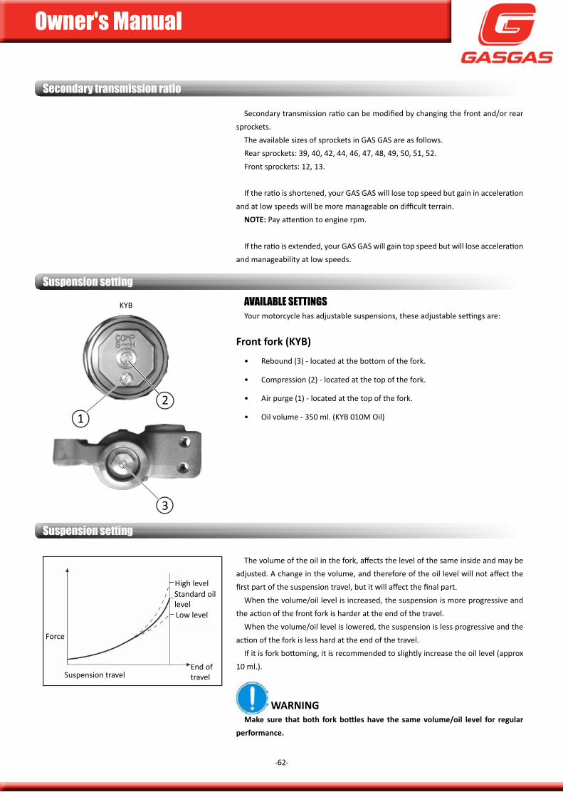
Owner's Manual
-62-
Secondary transmission ratio
secondary transmission ratio can be modified by changing the front and/or rear sprockets.
The available sizes of sprockets in gas gas are as follows.Rear sprockets: 39, 40, 42, 44, 46, 47, 48, 49, 50, 51, 52.front sprockets: 12, 13.
if the ratio is shortened, your gas gas will lose top speed but gain in acceleration and at low speeds will be more manageable on difficult terrain.
note: pay attention to engine rpm.
if the ratio is extended, your gas gas will gain top speed but will lose acceleration and manageability at low speeds.
Suspension setting
kyb availaBle SettinGSyour motorcycle has adjustable suspensions, these adjustable settings are:
front fork (Kyb)
• Rebound (3) - located at the bottom of the fork.
• compression (2) - located at the top of the fork.
• air purge (1) - located at the top of the fork.
• oil volume - 350 ml. (kyB 010m oil)
3
21
The volume of the oil in the fork, affects the level of the same inside and may be
adjusted. a change in the volume, and therefore of the oil level will not affect the first part of the suspension travel, but it will affect the final part.
When the volume/oil level is increased, the suspension is more progressive and the action of the front fork is harder at the end of the travel.
When the volume/oil level is lowered, the suspension is less progressive and the action of the fork is less hard at the end of the travel.
if it is fork bottoming, it is recommended to slightly increase the oil level (approx 10 ml.).
WarninGMake sure that both fork bottles have the same volume/oil level for regular
performance.
Suspension setting
suspension travelEnd of travel
High level
Low level
standard oil level
force
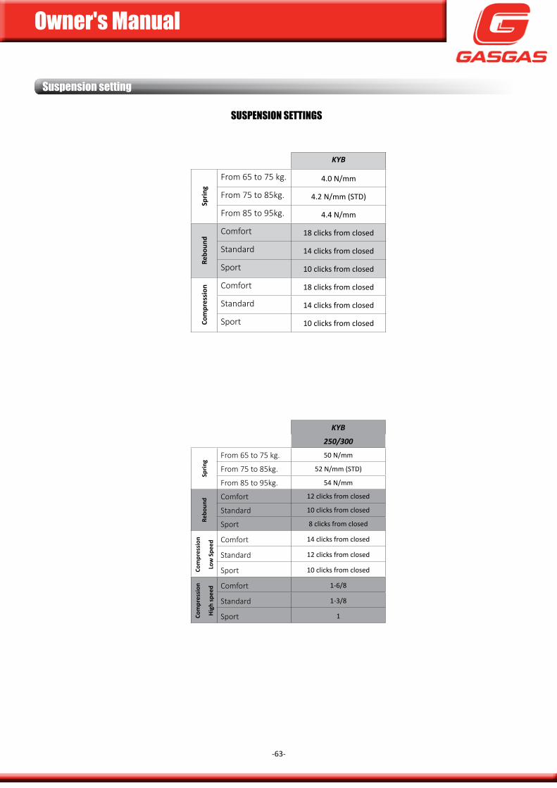
Owner's Manual
-63-
Suspension setting
KYB
sprin
g
From 65 to 75 kg. 4.0 n/mm
From 75 to 85kg. 4.2 n/mm (sTd)
From 85 to 95kg. 4.4 n/mmre
boun
d
Comfort 18 clicks from closed
Standard 14 clicks from closed
Sport 10 clicks from closed
com
pres
sion Comfort 18 clicks from closed
Standard 14 clicks from closed
Sport 10 clicks from closed
SuSPenSiOn SettinGS
KYB
250/300
sprin
g
From 65 to 75 kg. 50 n/mm
From 75 to 85kg. 52 n/mm (sTd)
From 85 to 95kg. 54 n/mm
rebo
und Comfort 12 clicks from closed
Standard 10 clicks from closed
Sport 8 clicks from closed
com
pres
sion
low
spe
ed
Comfort 14 clicks from closed
Standard 12 clicks from closed
Sport 10 clicks from closed
com
pres
sion
high
spee
d Comfort 1-6/8
Standard 1-3/8
Sport 1
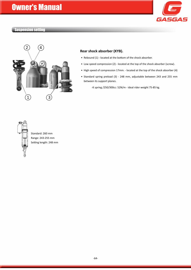
Owner's Manual
-64-
Suspension setting
rear shock absorber (Kyb).
• Rebound (1) - located at the bottom of the shock absorber.
• Low speed compression (2) - located at the top of the shock absorber (screw).
• High speed of compression 17mm. - located at the top of the shock absorber (4)
• standard spring preload (3) - 248 mm, adjustable between 243 and 255 mm between its support planes.
-k spring /250/300cc: 52n/m - ideal rider weight 75-85 kg.
1
2
3
4
standard: 260 mmRange: 243-255 mmsetting length: 248 mm
s
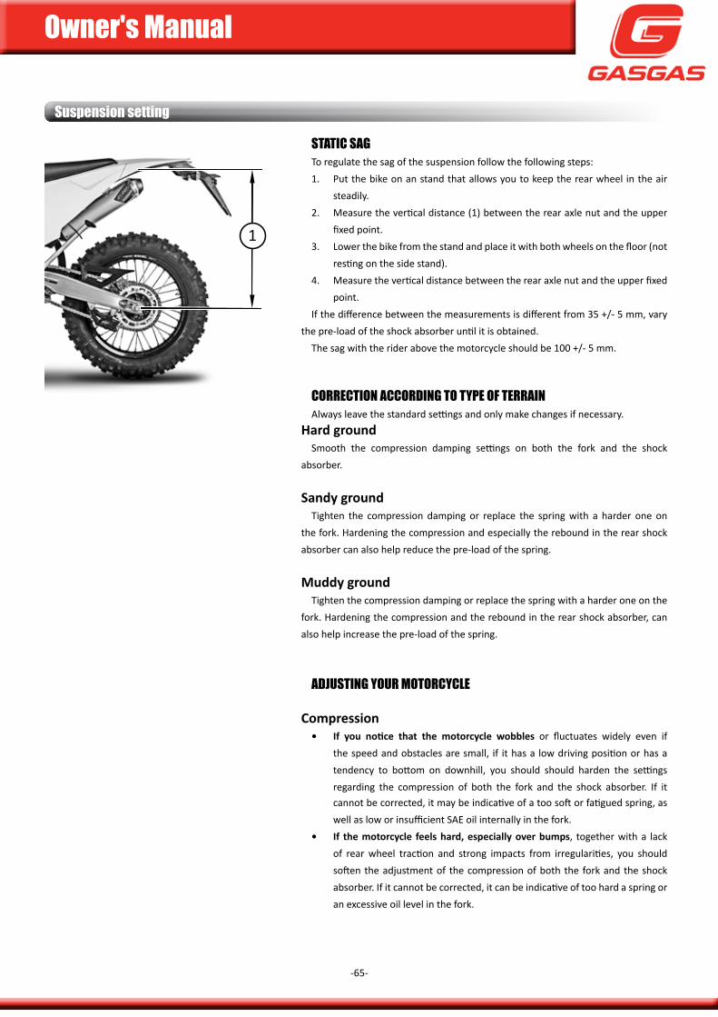
Owner's Manual
-65-
COrreCtiOn aCCOrDinG tO tyPe Of terrainalways leave the standard settings and only make changes if necessary.
hard groundsmooth the compression damping settings on both the fork and the shock
absorber.
sandy groundTighten the compression damping or replace the spring with a harder one on
the fork. Hardening the compression and especially the rebound in the rear shock absorber can also help reduce the pre-load of the spring.
muddy groundTighten the compression damping or replace the spring with a harder one on the
fork. Hardening the compression and the rebound in the rear shock absorber, can also help increase the pre-load of the spring.
StatiC SaGTo regulate the sag of the suspension follow the following steps:1. put the bike on an stand that allows you to keep the rear wheel in the air
steadily.2. measure the vertical distance (1) between the rear axle nut and the upper
fixed point.3. Lower the bike from the stand and place it with both wheels on the floor (not
resting on the side stand).4. measure the vertical distance between the rear axle nut and the upper fixed
point.if the difference between the measurements is different from 35 +/- 5 mm, vary
the pre-load of the shock absorber until it is obtained.The sag with the rider above the motorcycle should be 100 +/- 5 mm.
Suspension setting
aDjuStinG yOur MOtOrCyCle
compression• If you notice that the motorcycle wobbles or fluctuates widely even if
the speed and obstacles are small, if it has a low driving position or has a tendency to bottom on downhill, you should should harden the settings regarding the compression of both the fork and the shock absorber. if it cannot be corrected, it may be indicative of a too soft or fatigued spring, as well as low or insufficient saE oil internally in the fork.
• if the motorcycle feels hard, especially over bumps, together with a lack of rear wheel traction and strong impacts from irregularities, you should soften the adjustment of the compression of both the fork and the shock absorber. if it cannot be corrected, it can be indicative of too hard a spring or an excessive oil level in the fork.
1
Owner's Manual
-66-
suspension adjustment is a very critical adjustment, because if it is not done correctly it can deprive even the best rider of full performance on the motorcycle. check the suspension according to the rider and the terrain conditions.
When adjusting the suspension, you should not forget:
• if the bike is new, get used to the suspension for at least one hour of driving before making any changes.
• The factors to take into account are the weight of the rider, skill of the rider and the conditions of the terrain.
• if you have a problem, try changing your position on the bike to resolve it.
• The suspension must be adjusted to the rider's strengths. if you are fast on turns, you must adjust the suspension to this point.
• make changes in small increments as it is very easy to get past.
• The front and rear suspension must be balanced.
• When evaluating suspension, the rider must strive to ride consciously and recognize the effects of the change. a poor driver's position and/or fatigue will lead to an incorrect judgement of the settings.
• When the change for a particular terrain is well adjusted, the references should be noted for when you encounter similar terrain the next time.
• Lubricate the swingarm bearings, tie-rods, rocker arms and joints before making changes to prevent excessive friction affecting suspension operation.
rebound• If the motorcycle feels unstable or soft, if it easily loses its direction or
oscillates widely, although the speed and obstacles are small, you must tighten the adjustment of the rebound in both the fork and the shock absorber. if it cannot be corrected, it may be indicative of a too soft or fatigued spring, as well as low or insufficient saE oil internally in the fork.
• if the motorcycle is rigid with short suspension travel, along with lack of rear wheel traction and strong impacts of irregularities, you should soften the adjustment of the rebound in both the fork extension and the shock absorber. if it cannot be corrected, it can be indicative of too hard a spring or an excessive oil level in the fork.
WarninG
make only one adjustment on the set each time and test the effect it has on the motorcycle.
Suspension setting
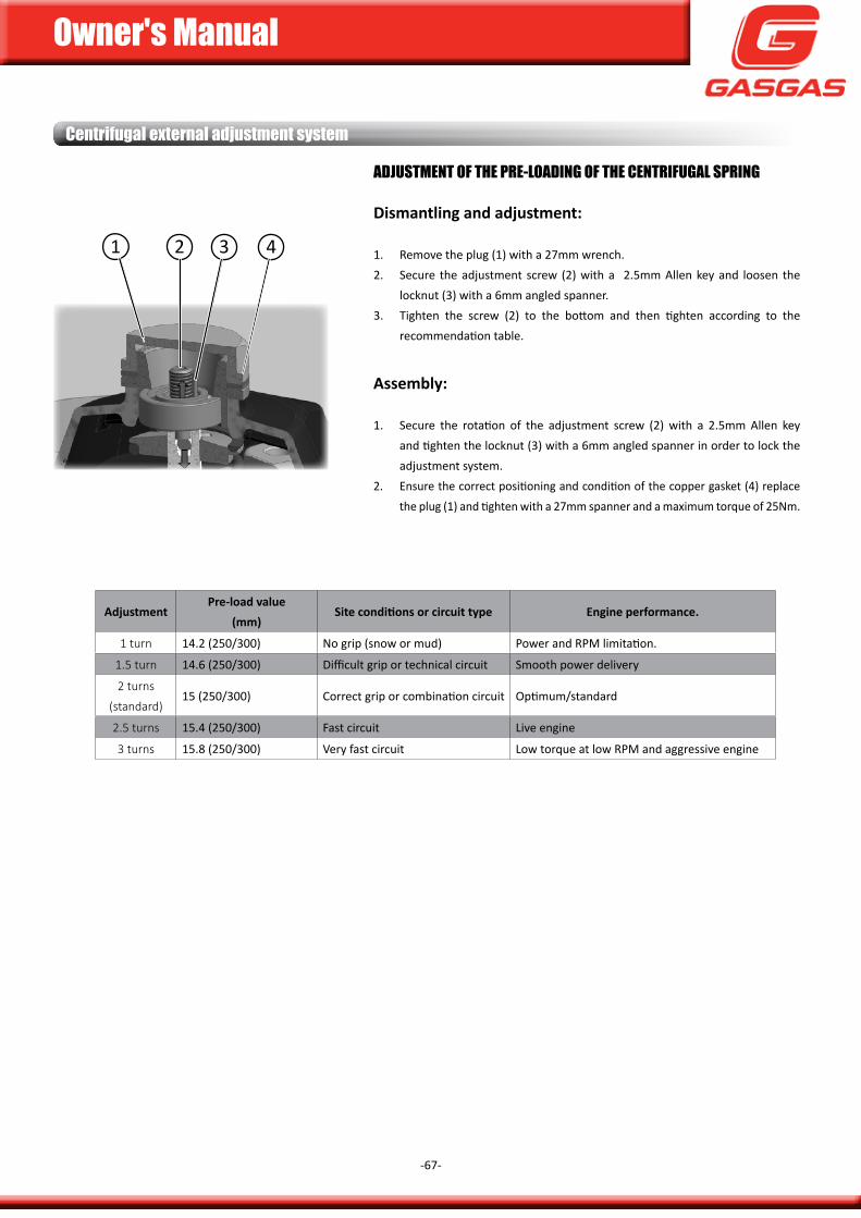
Owner's Manual
-67-
Centrifugal external adjustment system
aDjuStMent Of tHe Pre-lOaDinG Of tHe CentrifuGal SPrinG
Dismantling and adjustment:
1. Remove the plug (1) with a 27mm wrench.2. secure the adjustment screw (2) with a 2.5mm allen key and loosen the
locknut (3) with a 6mm angled spanner.3. Tighten the screw (2) to the bottom and then tighten according to the
recommendation table.
assembly:
1. secure the rotation of the adjustment screw (2) with a 2.5mm allen key and tighten the locknut (3) with a 6mm angled spanner in order to lock the adjustment system.
2. Ensure the correct positioning and condition of the copper gasket (4) replace the plug (1) and tighten with a 27mm spanner and a maximum torque of 25nm.
adjustmentpre-load value
(mm)Site conditions or circuit type engine performance.
1 turn 14.2 (250/300) no grip (snow or mud) power and Rpm limitation.
1.5 turn 14.6 (250/300) difficult grip or technical circuit smooth power delivery
2 turns
(standard)15 (250/300) correct grip or combination circuit optimum/standard
2.5 turns 15.4 (250/300) fast circuit Live engine
3 turns 15.8 (250/300) Very fast circuit Low torque at low Rpm and aggressive engine
1 2 3 4

Owner's Manual
-68-
This page has been left blank intentionally.
trOuBleSHOOtinG
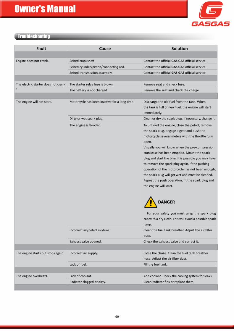
Owner's Manual
-69-
troubleshooting
fault cause Solution
Engine does not crank. seized crankshaft. contact the official Gas Gas official service.
seized cylinder/piston/connecting rod. contact the official Gas Gas official service.
seized transmission assembly. contact the official Gas Gas official service.
The electric starter does not crank 1
The starter relay fuse is blown Remove seat and check fuse.
The battery is not charged Remove the seat and check the charge.
The engine will not start. motorcycle has been inactive for a long time discharge the old fuel from the tank. When the tank is full of new fuel, the engine will start immediately.
dirty or wet spark plug. clean or dry the spark plug. if necessary, change it.
The engine is flooded. To unflood the engine, close the petrol, remove the spark plug, engage a gear and push the motorcycle several meters with the throttle fully open.Visually you will know when the pre-compression crankcase has been emptied. mount the spark plug and start the bike. it is possible you may have to remove the spark plug again, if the pushing operation of the motorcycle has not been enough, the spark plug will get wet and must be cleaned. Repeat the push operation, fit the spark plug and the engine will start.
DanGer
for your safety you must wrap the spark plug cap with a dry cloth. This will avoid a possible spark jump.
incorrect air/petrol mixture. clean the fuel tank breather. adjust the air filter duct.
Exhaust valve opened. check the exhaust valve and correct it.
The engine starts but stops again. incorrect air supply. close the choke. clean the fuel tank breather hose. adjust the air filter duct.
Lack of fuel. fill the fuel tank.
The engine overheats. Lack of coolant. add coolant. check the cooling system for leaks.
Radiator clogged or dirty. clean radiator fins or replace them.

Owner's Manual
-70-
it runs unevenly. spark plug dirty, broken or incorrectly adjusted. check the condition of the spark plug and clean it, adjust it or replace it.
spark plug cap problem. check the condition of the spark plug cap. check the good contact of the cable with the cap and the cable itself. change what is damaged.
ignition rotor damaged. change the rotor.
Water in the fuel. Empty the tank and put new fuel in
The engine lacks power or accelerates poorly.
The fuel supply is faulty. clean the fuel system and check it.
dirty air filter. clean or replace the air filter.
Exhaust damaged or is leaking. check if the exhaust system is damaged, renew the fibreglass in the muffler if necessary.
dirty carburettor jets. Remove the carburettor and clean the jets.
Worn or damaged crankshaft bearings. contact the official Gas Gas official service.
The engine emits strange sounds. ignition problem. contact the official Gas Gas official service.
overheating. see "The engine overheats".
The exhaust emits backfires. presence of carbon in the combustion chamber. contact the official Gas Gas official service.
poor quality petrol or bad octane. drain the petrol and introduce new and proper octane.
spark plug in poor condition or has inadequate specifications.
Replace spark plug with new and proper spark plug.
Exhaust system gaskets are deteriorated. check if the exhaust system is damaged. The gaskets must be in perfect condition, otherwise change them for new ones.
The exhaust emits white smoke. damaged cylinder head gasket (leakage of coolant to the cylinder).
contact the official Gas Gas official service.
The exhaust emits black smoke. clogged air filter. clean or replace the air filter.
The main jet is too high. check main jet.
The gears are not engaged. clutch does not disengage. contact the official Gas Gas official service.
shift fork bent or blocked. contact the official Gas Gas official service.
gear locked in transmission. contact the official Gas Gas official service.
gear shift lever damaged. Replace gear shift lever.
spring selector position loose or broken. contact the official Gas Gas official service.
Broken shift drum. contact the official Gas Gas official service.
gear ratchet spring broken. contact the official Gas Gas official service.
troubleshooting
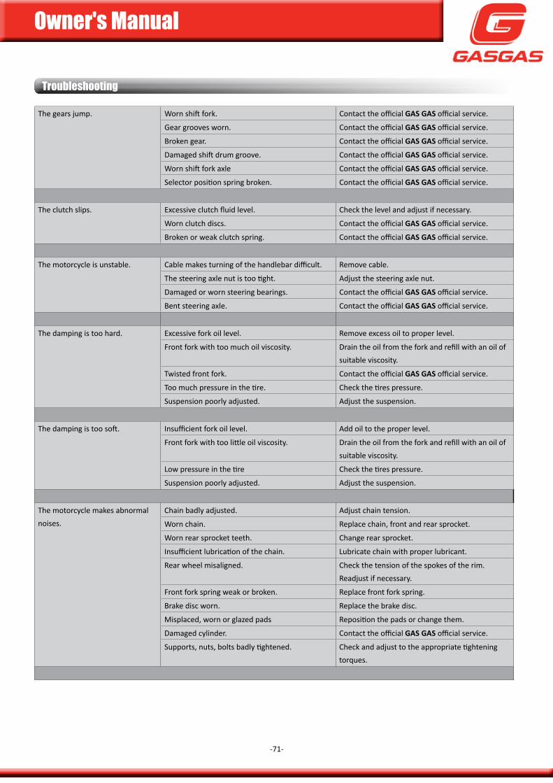
Owner's Manual
-71-
The gears jump. Worn shift fork. contact the official Gas Gas official service.
gear grooves worn. contact the official Gas Gas official service.
Broken gear. contact the official Gas Gas official service.
damaged shift drum groove. contact the official Gas Gas official service.
Worn shift fork axle contact the official Gas Gas official service.
selector position spring broken. contact the official Gas Gas official service.
The clutch slips. Excessive clutch fluid level. check the level and adjust if necessary.
Worn clutch discs. contact the official Gas Gas official service.
Broken or weak clutch spring. contact the official Gas Gas official service.
The motorcycle is unstable. cable makes turning of the handlebar difficult. Remove cable.
The steering axle nut is too tight. adjust the steering axle nut.
damaged or worn steering bearings. contact the official Gas Gas official service.
Bent steering axle. contact the official Gas Gas official service.
The damping is too hard. Excessive fork oil level. Remove excess oil to proper level.
front fork with too much oil viscosity. drain the oil from the fork and refill with an oil of suitable viscosity.
Twisted front fork. contact the official Gas Gas official service.
Too much pressure in the tire. check the tires pressure.
suspension poorly adjusted. adjust the suspension.
The damping is too soft. insufficient fork oil level. add oil to the proper level.
front fork with too little oil viscosity. drain the oil from the fork and refill with an oil of suitable viscosity.
Low pressure in the tire check the tires pressure.
suspension poorly adjusted. adjust the suspension.
The motorcycle makes abnormal noises.
chain badly adjusted. adjust chain tension.
Worn chain. Replace chain, front and rear sprocket.
Worn rear sprocket teeth. change rear sprocket.
insufficient lubrication of the chain. Lubricate chain with proper lubricant.
Rear wheel misaligned. check the tension of the spokes of the rim. Readjust if necessary.
front fork spring weak or broken. Replace front fork spring.
Brake disc worn. Replace the brake disc.
misplaced, worn or glazed pads Reposition the pads or change them.
damaged cylinder. contact the official Gas Gas official service.
supports, nuts, bolts badly tightened. check and adjust to the appropriate tightening torques.
troubleshooting
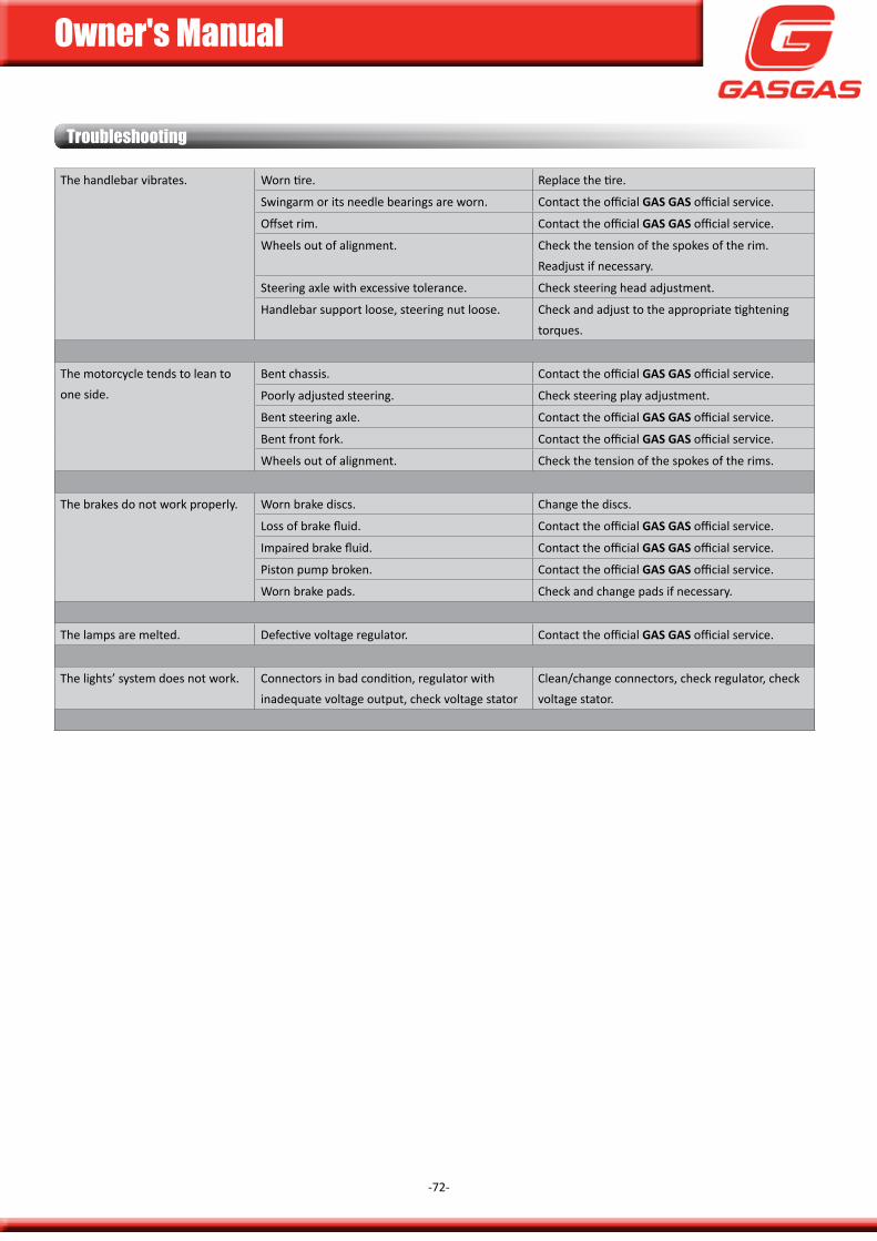
Owner's Manual
-72-
The handlebar vibrates. Worn tire. Replace the tire.
swingarm or its needle bearings are worn. contact the official Gas Gas official service.
offset rim. contact the official Gas Gas official service.
Wheels out of alignment. check the tension of the spokes of the rim. Readjust if necessary.
steering axle with excessive tolerance. check steering head adjustment.
Handlebar support loose, steering nut loose. check and adjust to the appropriate tightening torques.
The motorcycle tends to lean to one side.
Bent chassis. contact the official Gas Gas official service.
poorly adjusted steering. check steering play adjustment.
Bent steering axle. contact the official Gas Gas official service.
Bent front fork. contact the official Gas Gas official service.
Wheels out of alignment. check the tension of the spokes of the rims.
The brakes do not work properly. Worn brake discs. change the discs.
Loss of brake fluid. contact the official Gas Gas official service.
impaired brake fluid. contact the official Gas Gas official service.
piston pump broken. contact the official Gas Gas official service.
Worn brake pads. check and change pads if necessary.
The lamps are melted. defective voltage regulator. contact the official Gas Gas official service.
The lights’ system does not work. connectors in bad condition, regulator with inadequate voltage output, check voltage stator
clean/change connectors, check regulator, check voltage stator.
troubleshooting

Owner's Manual
-73-
Owner's Manual
-74-
This page has been left blank intentionally.
warranty Manual
Owner's Manual
-75-
warranty manual(according to Law 23/2003 of 10 July, on guarantees for the sale of consumer goods)
Gas Gas manufacturer's warranty rules.The company Gas Gas (hereinafter gg) hereby guarantees to the end consumer, purchaser of a vehicle manufactured by gg, that both
the materials and the manufacture are free from defects in accordance with the highest quality standards. consequently, gg hereby warrants to the final purchaser (hereinafter the "purchaser"), in accordance with the conditions set forth below, the repair of any defects in materials or workmanship detected on a new motorcycle free of charge within the warranty period and without any limitation as to the number of kilometres travelled or the number of hours of operation.
Warranty periodThe warranty period shall commence on the day of delivery of the vehicle to the purchaser by a gg licensing dealer, or in the case of
demonstration models, on the date the vehicle first starts operating. The seller is liable for any lack of conformity which becomes manifest within the time period established under the Law 23/2003 of July on Warranties in the sale of consumer goods from the time of delivery and in accordance with directive 1999/44/Ec for the rest of the member states of the European community. for countries outside the European community, the warranty period will be governed by the rules in force. However, if the lack of conformity becomes apparent during the first six months from the date of delivery of the motorcycle, it is presumed that this fault existed when it was delivered; from the sixth month, the consumer must prove that the non-conformity existed at the time of delivery of the goods. during the first six months after the delivery of the repaired good, the seller shall be liable for any lack of conformity which motivated the repair.
any defects detected in the product must be brought to the attention of a dealer authorized by gg within the warranty period. if the last day of the warranty period falls on a sunday or an official holiday, the warranty period will be extended in such a way that the last day of the warranty period is the first business day after the sunday or an official holiday.
Warranty claims for defects not brought to the attention of a dealer authorized by GG before the end of the warranty period will be excluded.
Obligations of the buyergg will be entitled to reject warranty claims if and to the extent that:a.) The buyer has not proceeded to subject the vehicle to any of the inspections and/or maintenance work required in the user manual
or has exceeded the date stipulated for such inspections or maintenance work; also excluded from the warranty are any defects that appear before the date set for an inspection or maintenance work that would have never been carried out, or that will be carried out after the established date.
b.) inspection, maintenance work or repair carried out by third parties not recognized or authorized by gg.c.) any maintenance or repair that has been carried out in breach of the technical requirements, specifications and instructions stated by
the manufacturer.d.) spare parts not authorized for use by gg in maintenance or repair work on the vehicle, or if, and to the extent that, the vehicle has been
applied with fuels, lubricants or other liquids (including, but not limited to, cleaning products) that have not been expressly stipulated in the specifications of the user manual.
e.) The vehicle has in any way been altered or modified or equipped with components other than those expressly authorized by gg as admitted vehicle components.
f.) The vehicle has been stored or transported in a manner inconsistent with the corresponding technical requirements.g.) The vehicle has been used for a special use other than ordinary use, such as competition, races or attempts to obtain a record.h.) The vehicle has suffered a fall or accident that directly or indirectly causes damage.
Warranty exclusionsThe following items will be excluded from the warranty:a.) Worn parts, including, but not limited to, spark plugs, batteries, fuel filters, oil filter element, chains (secondary), engine output
sprockets, rear sprockets, air filters, brake discs, brake pads, clutch discs, bulbs, fuses, carbon brushes, footrests, tires, chambers, cables and other rubber components.
b.) Lubricants (e.g. oil, grease, etc.) and operating fluids (e.g. battery fluid, coolant, etc.).
Owner's Manual
-76-
warranty manual
c.) inspection, adjustment and other maintenance work, as well as all types of cleaning work.d.) paint damage and consequent corrosion due to external influences such as stones, salt, industrial exhaust fumes and other environmental
impacts or improper cleaning with improper products.e.) damage caused by defects, as well as expenses caused directly or indirectly by incidents of defects (for example, communication
expenses, accommodation expenses, car rental expenses, public transportation expenses, crane expenses, express courier charges, etc. ), as well as other financial damages (for example, caused by loss of use of a vehicle, loss of revenue, loss of time, etc.).
f.) acoustic or aesthetic phenomenon that does not significantly affect the condition of use of the motorcycle (e.g. small or hidden imperfections, normal noise or vibration of use, etc.).
g.) phenomena due to the ageing of the vehicle (for example, discolouration of painted or metal coated surfaces).
Various1.) in the event that the repair or replacement of the part will be disproportionate, gg will have the prerogative to decide at its sole
discretion whether to repair or replace defective parts. The owner of the spare parts, if any, will be gg, without any other consideration. The gg authorized dealer who has been entrusted with the repair of defects will not be authorized to make binding declarations on behalf of gg.
2.) in cases of doubt as to the existence of a defect or if a visual or material inspection is required, gg reserves the right to require the shipment of the parts on which a warranty claim is based or to request a review of the defect by a gg expert. any additional warranty obligations on parts replaced free of charge or any service provided free of charge under this warranty will be excluded. The warranty for spare parts within the warranty period will expire on the expiration date of the warranty period of the respective product.
3.) if a defect cannot be repaired and its replacement is disproportionate to the manufacturer, the secured consumer shall be entitled to cancellation of the contract (payment of compensation) or partial reimbursement of the purchase price (discount), instead of motorcycle repair.
4.) The warranty claims of the buyer under the contract of sale with the corresponding authorized dealer will not be affected by this warranty. This warranty does not affect the buyer's additional contractual rights under the general conditions of business of the authorized dealer. such additional rights, however, can only be claimed from the authorized dealer.
5.) if the buyer resells the product within the warranty period, the terms and conditions of this warranty will continue to exist to the current extent, so that the claim rights under this warranty in accordance with the terms and conditions set forth in this document will be transferred to the new owner of the motorcycle.