
2017 Collegiate Design Series SAE Aero Design Rules · PDF file1.2 SAE Aero Design Rules and...
60
2017 Collegiate Design Series SAE Aero Design Rules
Transcript of 2017 Collegiate Design Series SAE Aero Design Rules · PDF file1.2 SAE Aero Design Rules and...

2017 Collegiate Design Series
SAE Aero Design Rules
i
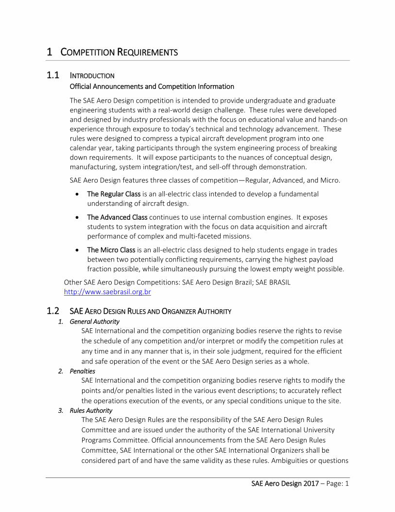
Forward Welcome to SAE Aero Design 2017. Each year, we as a Rules Committee strive to write competition
rules that are easy to understand, and that present students of all engineering disciplines and levels
of experience with relevant real-world challenges. As such, the SAE Aero Design competition is
broken down into three classes including Regular, Micro and Advanced to fit your level of
experience and interest. The Regular Class is designed to be an entry level class but tends to draw
students at all levels of experience. Micro Class is more challenging because of having to deal with
low Reynold’s Number flight and the form factor of the containerized aircraft. Advanced Class is
made to be the most challenging with a set of multidisciplinary challenges. In the past, teams have
struggled with system reliability in Advanced Class because the many systems need to function
flawlessly together. Remember that with five separate systems, each having 80% reliability, the
whole system has only a 33% operational uptime (0.8^5). Keep this in mind when designing your
aircraft and setting performance goals for each subsystem.
For 2017, the most significant changes were made to Regular Class. In the past, Regular had a
simple goal of reliably lifting the highest weight with limited power and overall dimensional
constraints. This year, the goal with Regular is to reliably lift the most “Passengers” and “Luggage”
and thereby maximize Total Revenue, with limited power available. The number of seated
Passengers and Luggage work to increase revenue, whereas Empty Seats work to reduce revenue;
similar to the challenges faced by commercial airlines. From a design standpoint, you’ll need to
select an optimal number of passenger seats for your aircraft so you can consistently fly a full
aircraft and avoid the penalty of empty seats. For standardization, filled seats are represented by
unmodified industry standard tennis balls. In building your design optimization routines you’ll want
to consider the effect of Passenger Bay volume on aerodynamic performance. In past years, the
Regular Class aircraft fuselage volume was small and accounted for a relatively small component
of the overall drag. This year you’ll find that the fuselage volume has a more significant effect on
drag and therefore impacts your optimal design. Beyond Regular Class, there are a number of
changes and clarifications throughout the rules. The significant changes are noted in colored text;
pay particular attention to these. As always, read and reread the rules.
After 13 years of being involved in this competition I believe this year has one of the most industry-
relevant and challenging rule sets to date. I’m expecting the East and West competition to sell out
very quickly this year, so be sure to sign up early. If you are unfortunate enough to be a waitlisted
team, I encourage you to move forward with your design and plan to attend. Last year, all
waitlisted teams were contacted and invited to attend. We have an exciting competition year
ahead of ourselves. I hope you’re up to the challenge and I look forward to seeing you at the
competition!! Good luck.
Brian Czapor | Rules Committee Chair

ii
TABLE OF CONTENTS 1 Competition Requirements ........................................................................................................... 1
1.1 Introduction ........................................................................................................................... 1
1.2 SAE Aero Design Rules and Organizer Authority .................................................................. 1
1. General Authority .................................................................................................................. 1
2. Penalties ................................................................................................................................. 1
3. Rules Authority....................................................................................................................... 1
4. Rules Validity .......................................................................................................................... 2
5. Rules Compliance ................................................................................................................... 2
6. Understanding the Rules ....................................................................................................... 2
7. Loopholes ............................................................................................................................... 2
8. Participating in the Competition ........................................................................................... 2
9. Visa--United States Visas ....................................................................................................... 2
10. Letters of Invitation ............................................................................................................ 3
11. Certificates of Participation ............................................................................................... 3
12. Violations of Intent ............................................................................................................ 3
13. Right to Impound ............................................................................................................... 3
1.3 Society Membership and Eligibility ....................................................................................... 3
1. Society Membership .............................................................................................................. 3
2. Team Pilots ............................................................................................................................. 3
1.4 Liability Waiver and Insurance Requirements ...................................................................... 3
1.5 Ringers Prohibited ................................................................................................................. 4
1.6 Design and Fabrication .......................................................................................................... 4
1.7 Original Design ....................................................................................................................... 4
1.8 Official Languages .................................................................................................................. 4
1.9 Unique Designs ...................................................................................................................... 5
1.10 Aircraft Classification/Duplicate Aircraft .............................................................................. 5
1. One Aircraft per class ............................................................................................................ 5
2. Backup Aircraft ....................................................................................................................... 5
3. Scoring with Backup Aircraft ................................................................................................. 5
1.11 Aircraft Eligibility .................................................................................................................... 5

iii
1.12 Registration Information, Deadlines and Waitlist (NEW) .................................................... 6
1. Team/Class/University Policy ................................................................................................ 6
2. Individual Registration Requirements – ACTION REQUIRED ............................................... 6
1.13 Waitlist ................................................................................................................................... 6
1.14 Policy Deadline ....................................................................................................................... 7
1. Failure to meet deadlines ...................................................................................................... 7
2. Late Submission Penalty ........................................................................................................ 7
3. Automatic Withdrawal Policy ................................................................................................ 7
1.15 Faculty Advisor ....................................................................................................................... 8
1.16 Questions, Complaints and Appeals ..................................................................................... 8
1. Questions ............................................................................................................................... 8
2. Complaints ............................................................................................................................. 8
3. Appeal / Preliminary Review ................................................................................................. 8
4. Cause for Appeal .................................................................................................................... 8
5. Appeal Format........................................................................................................................ 9
6. Appeals Period ....................................................................................................................... 9
7. Appeals Committee ............................................................................................................... 9
1.17 Professional Conduct ............................................................................................................. 9
1. Unsportsmanlike Conduct ..................................................................................................... 9
2. Arguments with Officials ....................................................................................................... 9
3. Alcohol and Illegal Material ................................................................................................. 10
4. Organizer’s Authority ........................................................................................................... 10
5. Ground Safety and Flight Line Safety Equipment .............................................................. 10
1.18 SAE Technical Standards Access ......................................................................................... 10
2 General Aircraft Requirements ................................................................................................... 11
2.1 Aircraft Identification ........................................................................................................... 11
2.2 No lighter-than-air or rotary wing aircraft ......................................................................... 11
2.3 Empty CG design requirement and Empty CG markings on aircraft ................................. 11
2.4 Gross Weight Limit............................................................................................................... 11
2.5 Controllability ....................................................................................................................... 12
2.6 Radio Control System .......................................................................................................... 12

iv
2.7 Spinners or Safety Nuts Required ....................................................................................... 12
2.8 Metal propellers................................................................................................................... 12
2.9 Lead is prohibited ................................................................................................................ 12
2.10 Payload Distribution ............................................................................................................ 12
2.11 Aircraft Ballast ...................................................................................................................... 12
2.12 Stored Energy Restriction .................................................................................................... 12
2.13 Control Surface Slop ............................................................................................................ 12
2.14 Servo Sizing .......................................................................................................................... 12
2.15 Clevis Keepers ...................................................................................................................... 12
2.16 Red Arming Plug ................................................................................................................... 13
2.17 Repairs, Alterations, and Spares ......................................................................................... 13
2.18 Alteration after First Flight .................................................................................................. 13
2.19 Competition Supplied Fuel .................................................................................................. 13
3 Mission Requirements................................................................................................................. 14
3.1 Round Attempt .................................................................................................................... 14
3.2 Engine or Motor Run-Up Before Takeoff ............................................................................ 14
3.3 Aircraft Configuration at Liftoff and During the Flight Attempt ........................................ 14
3.4 Competition Circuit Requirements ..................................................................................... 14
3.5 Time Limits and Multiple Flight Attempt s ......................................................................... 15
3.6 Take-off ................................................................................................................................ 15
3.7 Landing ................................................................................................................................. 16
3.8 Landing Zone ........................................................................................................................ 16
1. Allowed during Landing ....................................................................................................... 16
2. Not Allowed during Landing ................................................................................................ 16
3.9 Grounding an Aircraft .......................................................................................................... 16
3.10 No-Fly Zone .......................................................................................................................... 17
3.11 Flight Rules Announcement ................................................................................................ 17
3.12 Flight Rules Violations .......................................................................................................... 17
3.13 Local Field Rules ................................................................................................................... 17
4 Design Report .............................................................................................................................. 18
4.1 Submission Deadlines .......................................................................................................... 18
v
4.2 Original Work ....................................................................................................................... 18
4.3 Technical Design Report Requirements ............................................................................. 19
4.4 2D Drawing Requirements .................................................................................................. 20
1. 2D Format and Size .............................................................................................................. 20
2. Markings Required ............................................................................................................... 20
3. Views Required .................................................................................................................... 20
4. Dimensions Required ........................................................................................................... 20
5. Summary Data Required ..................................................................................................... 20
6. Weight and Balance Information ........................................................................................ 21
4.5 Tech Data Sheet: Payload Prediction (Regular Class Only) ................................................ 21
4.6 Tech Data Sheet: Radio Link Budget (Advanced Class Only) ............................................. 22
4.7 Tech Data Sheet: Weight Buildup (Micro Class Only) ........................................................ 22
5 Technical Presentation ................................................................................................................ 23
5.1 Technical Presentation Requirements ................................................................................ 23
5.2 Regular Class Payload Loading and Unloading Demonstration ......................................... 23
5.3 Technical Presentation Process and Procedures ............................................................... 24
6 Technical Inspection .................................................................................................................... 25
6.1 Aircraft Conformance to 2D drawing .................................................................................. 25
6.2 Deviations from 2D drawing ................................................................................................ 25
6.3 Failure to report design changes ........................................................................................ 25
6.4 Safety and airworthiness of aircraft .................................................................................... 26
6.5 Inspection of spare aircraft and spare aircraft components. ............................................ 26
6.6 Aircraft must meet all inspection requirements throughout the competition. ............... 26
6.7 Technical and safety inspection penalties .......................................................................... 26
7 Regular Class Design Requirements ........................................................................................... 27
7.1 Aircraft Dimension Requirement ........................................................................................ 27
7.2 Material and Equipment Restrictions for Regular Class .................................................... 27
1. Fiber-Reinforced Plastic (FRP) ............................................................................................. 27
2. Rubber bands ....................................................................................................................... 27
3. Stability Assistance............................................................................................................... 27
7.3 Aircraft System Requirements ............................................................................................ 27

vi
1. Electric Motor Requirements .............................................................................................. 27
2. Gear boxes, Drives, and Shafts ............................................................................................ 27
3. Aircraft Propulsion System Battery ..................................................................................... 27
4. Power Limiter ....................................................................................................................... 27
5. Radio System Battery ........................................................................................................... 28
7.4 Payload Requirements ......................................................................................................... 28
1. Types of Payload .................................................................................................................. 28
2. Cargo Bay Requirements ..................................................................................................... 28
3. Luggage and Luggage Support Requirements .................................................................... 29
4. Passenger Payload Definition .............................................................................................. 29
5. Passenger Cabin Requirements .......................................................................................... 29
7.5 Regular Class Scoring ........................................................................................................... 30
8 Advanced Class Design Requirements........................................................................................ 31
8.1 Video documentation of proven operational ability for Advanced class ......................... 31
8.2 Aircraft Dimension Requirement ........................................................................................ 31
8.3 Engine Requirements .......................................................................................................... 31
8.4 Radio System Battery ........................................................................................................... 31
8.5 Rubber Bands ....................................................................................................................... 32
Payload Requirements ............................................................................................................ 32
8.6 .................................................................................................................................................... 32
1. Releasable Payload Requirements ...................................................................................... 32
2. Static Payload Requirements .............................................................................................. 33
8.7 Gyroscopic and other stability augmentation .................................................................... 33
8.8 Autonomous flight ............................................................................................................... 33
8.9 Data Acquisition System (DAS) ............................................................................................ 33
8.10 First Person View System (FPV)........................................................................................... 33
8.11 DAS and FPV Failures ........................................................................................................... 34
8.12 Payload Specialist ................................................................................................................. 34
8.13 Link Budget Format for SAE Aero Design Competition ...................................................... 34
8.14 Flight & Drop Procedures .................................................................................................... 35
8.15 Advance Class Scoring ......................................................................................................... 36

vii
1. Zone Multiplier ..................................................................................................................... 36
2. Scoring Equation .................................................................................................................. 36
9 Micro Class Design Requirements .............................................................................................. 37
9.1 Aircraft Systems Requirements ........................................................................................... 37
9.2 Payload Requirements ......................................................................................................... 37
9.3 Micro Class Aircraft Launch ................................................................................................. 38
9.4 Micro Class Aircraft Hand-Launch Safety Requirements ................................................... 39
9.5 Aircraft System Container ................................................................................................... 39
9.6 Timed Aircraft Assembly ...................................................................................................... 40
9.7 Mission Requirements ......................................................................................................... 41
9.8 Micro Class Flight Scoring .................................................................................................... 42
10 Future Rule Changes ................................................................................................................ 43
Appendix A............................................................................................................................................. 1
Appendix B ............................................................................................................................................. 2
Appendix C ............................................................................................................................................. 3
Appendix D ............................................................................................................................................ 4
Appendix E ............................................................................................................................................. 6
Appendix F ............................................................................................................................................. 7
SAE Aero Design 2017 – Page: 1
1 COMPETITION REQUIREMENTS
1.1 INTRODUCTION Official Announcements and Competition Information
The SAE Aero Design competition is intended to provide undergraduate and graduate engineering students with a real-world design challenge. These rules were developed and designed by industry professionals with the focus on educational value and hands-on experience through exposure to today’s technical and technology advancement. These rules were designed to compress a typical aircraft development program into one calendar year, taking participants through the system engineering process of breaking down requirements. It will expose participants to the nuances of conceptual design, manufacturing, system integration/test, and sell-off through demonstration.
SAE Aero Design features three classes of competition—Regular, Advanced, and Micro.
The Regular Class is an all-electric class intended to develop a fundamental understanding of aircraft design.
The Advanced Class continues to use internal combustion engines. It exposes students to system integration with the focus on data acquisition and aircraft performance of complex and multi-faceted missions.
The Micro Class is an all-electric class designed to help students engage in trades between two potentially conflicting requirements, carrying the highest payload fraction possible, while simultaneously pursuing the lowest empty weight possible.
Other SAE Aero Design Competitions: SAE Aero Design Brazil; SAE BRASIL http://www.saebrasil.org.br
1.2 SAE AERO DESIGN RULES AND ORGANIZER AUTHORITY 1. General Authority
SAE International and the competition organizing bodies reserve the rights to revise
the schedule of any competition and/or interpret or modify the competition rules at
any time and in any manner that is, in their sole judgment, required for the efficient
and safe operation of the event or the SAE Aero Design series as a whole. 2. Penalties
SAE International and the competition organizing bodies reserve rights to modify the
points and/or penalties listed in the various event descriptions; to accurately reflect
the operations execution of the events, or any special conditions unique to the site. 3. Rules Authority
The SAE Aero Design Rules are the responsibility of the SAE Aero Design Rules
Committee and are issued under the authority of the SAE International University
Programs Committee. Official announcements from the SAE Aero Design Rules
Committee, SAE International or the other SAE International Organizers shall be
considered part of and have the same validity as these rules. Ambiguities or questions

SAE Aero Design 2017 – Page: 2
concerning the meaning or intent of these rules will be resolved by the officials, SAE
International Rules Committee or SAE International Staff. 4. Rules Validity
The SAE Aero Design Rules posted on the SAE International Website (www.sae.org)
and dated for the calendar year of the competition are the rules in effect for the
competition. Rule sets dated for other years are invalid. 5. Rules Compliance
By entering an SAE Aero Design competition, the team members, faculty advisors and
other personnel of the entering university agree to comply with, and be bound by,
the rules and all rules interpretations or procedures issued or announced by SAE
International, the SAE Aero Design Rules Committee and other organizing bodies. All
team members, faculty advisors and other university representatives are required to
cooperate with, and follow all instructions from competition organizers, officials and
judges. 6. Understanding the Rules
Teams are responsible for reading and understanding the rules in their entirety for
the competition in which they are participating. The section and paragraph headings
in these rules are provided to facilitate reading: they do not affect the paragraph
contents. 7. Loopholes
It is virtually impossible for a set of rules to be so comprehensive that it covers all
possible questions about the aircraft’s design parameters or the conduct of the
competition. Please keep in mind that safety remains paramount during any SAE
International competition, so any perceived loopholes should be resolved in the
direction of increased safety/ concept of the competition. 8. Participating in the Competition
Teams, team members as individuals, faculty advisors and other representatives of a
registered university who are present on-site at a competition are considered to be
“participating in the competition” from the time they arrive at the event site until
they depart the site at the conclusion of the competition or earlier by withdrawing. 9. Visa--United States Visas
Teams requiring visas to enter to the United States are advised to apply at least sixty
(60) days prior to the competition. Although most visa applications seem to go
through without an unreasonable delay, occasionally teams have had difficulties and
in several instances visas were not issued before the competition.
Affiliated CDS Student Team Members will have the ability to print out a
Registration Confirmation Letter for the individual event(s) that they are attending.
Once a student team member affiliates themselves to their teams profile page under
their individual edit section. They will have the opportunity to print out their
personalized letter with the following information: Student’s Name, School’s Name,
the CDS Event Name, Official Dates and Location(s).

SAE Aero Design 2017 – Page: 3
10. Letters of Invitation
Neither SAE International staff nor any competition organizers are permitted to give
advice on visas, customs regulations or vehicle shipping regulations concerning the
United States or any other country. 11. Certificates of Participation
Any affiliated team member can print a personalized Certificate of Participation on
their Team Profile page at any point during the competition season. Certificates will
not be available after the competition season concludes. Competition organizers do
not issue certificate of participation. 12. Violations of Intent
The violation of the intent of a rule will be considered a violation of the rule itself.
Questions about the intent or meaning of a rule may be addressed to the SAE
International Officials, Competition Organizers or SAE International Staff. 13. Right to Impound
SAE International and the other competition organizing bodies reserve the right to
impound any on-site vehicle/aircraft at any time during a competition for inspection
and examination by the organizers, officials and technical inspectors.
1.3 SOCIETY MEMBERSHIP AND ELIGIBILITY 14. Society Membership
Individual team members must be members of one of the following societies: (1) SAE
International or an SAE International affiliate society, (2) ATA, or (3) IMechE or (4)
VDI. Proof of membership, such as a membership card, is required at the event.
Students who are members of one of the societies listed above are not required to
join any of the other societies in order to participate in any SAE competition. Students
may join online at http://www.sae.org/students
Teams are also required to read the articles posted on the SAE Aero Design News
Feed ( http://students.sae.org/cds/aerodesign/news ) published by SAE International
and the other organizing bodies. Teams must also be familiar with all official
announcements concerning the competitions and rule interpretations released by the
SAE Aero Design Rules Committee. 15. Team Pilots
Team pilots are not required to be students or SAE International members, but they
must be current members of either the Academy of Model Aeronautics or the
national model aircraft club in their country of origin (such as the MAAC for Canadian
teams). Valid AMA membership cards must be presented at the flying field prior to
flying any team’s aircraft. Copies of AMA application forms will not suffice as proof of
AMA membership; the actual AMA card must be presented at the event flying field.
1.4 LIABILITY WAIVER AND INSURANCE REQUIREMENTS
All on-site participants and faculty advisors are required to sign a liability waiver prior to or upon registration. Individual medical and accident insurance coverage is the sole responsibility of the participant.
SAE Aero Design 2017 – Page: 4
1.5 RINGERS PROHIBITED
In order to maintain the integrity of a fair competition, the faculty advisor must prohibit ringers. A ringer is someone that has exceptional skills related to the competition (e.g., a professional model builder) that cannot be a legal member of the team but helps the team win points.
1.6 DESIGN AND FABRICATION
The aircraft must be designed and built by the SAE International student members without direct involvement from professional engineers, radio control model experts, pilots, machinists, or related professionals. The students may use any literature or knowledge related to R/C aircraft design and construction and information from professionals or from professors as long as the information is given as discussion of alternatives with their pros and cons and is acknowledged in the references in the design report. Professionals may not make design decisions, nor contribute to the drawings, the report, or the construction of the aircraft. The faculty advisor must sign the Statement of Compliance given in the Appendix.
1.7 ORIGINAL DESIGN
Any aircraft presented for competition must be an original design whose configuration is conceived by the student team members. Photographic scaling of an existing model aircraft design is not allowed. Use of major components such as wings, fuselage, or empennage of existing model aircraft kits is prohibited. Use of standard model aircraft hardware such as engine mounts, control horns, and landing gear is allowed.
1.8 OFFICIAL LANGUAGES
The official language of the SAE Aero Design series is English. Document submissions, presentations and discussions in English are acceptable at all competitions in the series.
Team members, judges and officials at Non U.S. competition events may use their respective national languages for document submissions, presentations and discussions if all the parties involved agree to the use of that language.
SAE Aero Design East English
SAE Aero Design West English
SAE Aero Design Brazil Portuguese and English

SAE Aero Design 2017 – Page: 5
1.9 UNIQUE DESIGNS
Universities may enter more than one team in each SAE Aero Design competition, but each entry must be a unique design, significantly different from each other. If the aircraft are not significantly different in the opinion of the rules committee and organizer, then the university will be considered to have only a single entry and only one of the teams and its aircraft will be allowed to participate in the competition. For example, two aircraft with identical wings and fuselages but different empennage would likely not be considered significantly different. For guidance regarding this topic, please email [email protected]
1.10 AIRCRAFT CLASSIFICATION/DUPLICATE AIRCRAFT 1. One Aircraft per class
A university or college can only have one aircraft registered for one class. A university
cannot register more than one team per class.
2. Backup Aircraft
When a team has an identical aircraft as a back-up, the back-up aircraft must go
through inspection with the primary aircraft.
3. Scoring with Backup Aircraft
Team will forfeit all flight points earned with the original aircraft if the team decides
to fly with an entirely new aircraft.
1. If a team decides to replace more than 50% of the original aircraft with spare
parts, the team will forfeit all flight points earned with the original aircraft
2. If a team decides to replace less than 50% of the original aircraft with spare parts,
the team will retain all flight points earned with the original aircraft
Once the spare parts have successfully flown with original parts of the aircraft, the
spare part will no longer be classified as spare.
1.11 AIRCRAFT ELIGIBILITY Aircraft will only be allowed to compete during a single academic year. Aircraft may be
entered in both SAE Aero Design East and SAE Aero Design West during the same
calendar year, but that same aircraft may not be used in either competition during the
following year. Entering the same aircraft in SAE Aero Design West one year and SAE
Aero Design East the next year is not allowed.

SAE Aero Design 2017 – Page: 6
1.12 REGISTRATION INFORMATION, DEADLINES AND WAITLIST (NEW) Teams intending to participate in the 2017 SAE Aero Design competitions must register their
teams online per the open registration schedule.
Registration Fee: $1000
Registration Limit: 75 Registered Teams / 40 Waitlist Teams
All Classes Online Registration Open: Monday, October 3, 2016 at 10:00 AM EST
All Classes Online Registration Close: Monday, November 14, 2016 at 10:00 AM EST
The registration fee is non-refundable and failure to meet these deadlines will be
considered a failure to qualify for the competition. Separate entry fees are required for
the East and West events. 1. Team/Class/University Policy
A university or college can only have one aircraft registered for one class. A university
cannot register more than one team per class. Teams must pay the registration fees or
provide proof that the payment has been initiated as indicated on the website ($1000)
within 48 business hours of registration.
Individual Registration Requirements – ACTION REQUIRED
All participating team members and faculty advisors must be sure that they are
individually affiliated to their respective school / university on the SAE International
website (www.sae.org) event registration page.
If you are not an SAE International member, go to www.sae.org and select the
“Membership” link. Students will need to select the “Student Membership” link and then
follow the series of questions that are asked Please note all student participants must be
SAE International members to participate in the events.
Faculty members who wish to become SAE International members should choose the
“Professional Membership” link. Please note: this is not mandatory for faculty advisors.
However, Faculty members must be affiliated on the team roster using a free customer
account.
All student participants and faculty advisors must affiliate themselves to the appropriate
team(s) online.
The “Add New Member” button will allow individuals to access this page and include the
necessary credentials. If the individual is already affiliated to the team, simply select the
Edit button next to the name. Please be sure this is done separately for each of the
events your team has entered.
All students, both domestic and international, must affiliate themselves online prior to
the competition.
**NOTE: When your team is registering for a competition, only the student or faculty
advisor completing the registration needs to be linked to the school. All other students and
faculty can affiliate themselves after registration has been completed.

SAE Aero Design 2017 – Page: 7
Waitlist
Once an event reaches the 75 team capacity, all remaining registered team will be placed
on a waitlist. The waitlist is capped at 40 available spaces per event and will close on the
same day as registration. Once another team withdraws from an event, an SAE
International Staff member will inform your team by email (the individual who registered
the team to the waitlist) that a spot on the registered teams list has opened. You will
have 24 hours to accept or reject the position and an additional 48 business hours to
have the registration payment completed or process for payment begun. Waitlisted
teams are required to submit all documents by the deadlines in order to be considered
serious participants and any team that does not submit all documents will be withdrawn
from the waitlist.
1.13 POLICY DEADLINE 1. Failure to meet deadlines
Teams registering for SAE Aero Design competitions are required to submit a number of
documents prior to the competition including a Design Report, Technical Data Sheet, and
Drawings that the event judges need to evaluate the team during the competition. When
these documents are not submitted our judges cannot properly assess the team.
Additionally, teams that do not submit a Design Report typically do not come to the
competition. Teams that do not notify us that they are withdrawing create the following
problems
1. They are included in the static event schedules and judging time is wasted.
2. Their unused registration slot cannot be offered to a team on the waitlist.
Additionally, failure to submit the required Design Report is a clear violation of
the rules. 2. Late Submission Penalty
Late submission or failure to submit the Design Report will be penalized five (5) points
per day. If your Design Report is received more than five (5) days late it will be classified
as “Not Submitted” and your team will not participate and the automatic withdrawn
policy will be in effect (see section 3).
3. Automatic Withdrawal Policy
Failure to submit the required Design Report, Technical Data Sheet, and Drawings within
5 days of the deadline will constitute an automatic withdrawal of your team. Your team
will be notified of no submission that we have not received your documents and after the
5 days, your team’s registration will be cancelled and no refund will be given.

SAE Aero Design 2017 – Page: 8
1.14 FACULTY ADVISOR Each team is expected to have a Faculty Advisor appointed by the university. The Faculty
Advisor is expected to accompany the team to the competition and will be considered by
competition officials to be the official university representative. Faculty Advisors may
advise their teams on general engineering and engineering project management theory,
but may not design any part of the vehicle nor directly participate in the development of
any documentation or presentation. Additionally Faculty Advisors may neither fabricate
nor assemble any components nor assist in the preparation, maintenance, or testing of
the vehicle. In Brief - Faculty Advisors may not design, build or repair any part of the
aircraft.
1.15 QUESTIONS, COMPLAINTS AND APPEALS 1. Questions
Any questions or comments about the rules should be brought to the attention of the
Rules Committee via the Rules Q&A on https://www.saeaerodesign.com.
General information about hotels and other attractions in the area as well as a schedule
of events will be posted on the SAE International website according to the competition in
which you are competing: http://students.sae.org/competitions/aerodesign/ 2. Complaints
Competition officials will be available to listen to complaints regarding errors in scoring,
interpretation, or application of the rules during the competition. Competition officials
will not be available to listen to complaints regarding the nature, validity, or efficacy of
the rules themselves at the competition. In other words, the Organizer will not change
the rulebook at the field. 3. Appeal / Preliminary Review
A team can only appeal issues related to own-team scoring, judging, venue policies,
and/or any official actions. Team Captain(s) and/or faculty advisor must bring the issue
to the Organizer’s or SAE International staff’s attention for an informal preliminary review
before filing an official appeal.
A team cannot file an appeal to cause harm to another team’s standing and/or score. 4. Cause for Appeal
A team may appeal any rule interpretation, own-team scoring or official actions which
the team feel has caused some actual, non-trivial, harm to own-team, or has had a
substantive effect on their score.
Teams may not appeal rule interpretations or actions that have not caused them any
substantive damage.

SAE Aero Design 2017 – Page: 9
5. Appeal Format
If a faculty advisor or team captain(s) feel that their issue regarding an official action or
rules interpretation was not properly addressed by the event officials, the team may file a
formal appeal to the action or rules interpretation with the Appeals Committee.
All appeals must be filed in writing (see Appendix E) to the Organizer by the faculty
advisor or team captain only.
All appeals will require the team to post twenty five (25) points as collateral. If the
appeal is successful and the action is reversed, the team will not forfeit the twenty five
(25) collateral points. If the appeal is overruled, the team will forfeit the twenty five (25)
collateral points.
All rulings issued by the Appeals Committee are final.
6. Appeals Period
All appeals must be submitted within thirty (30) minutes of the end of the flight round or
other competition event to which the appeal relates. 7. Appeals Committee
When a timely appeal is received, the committee will review in detail the claims. All
contentions or issues raised in the formal appeal will be addressed in a timely manner.
The consideration in each review is whether the actions in dispute were just and in-line
with the intent of the rules. Once the review is completed, a new order will be issued
affirming, reversing or modifying the original determination.
All rulings issued by the Appeals Committee are final.
The Appeals Committee must consist of a minimum of three members: the Organizer or
delegate, SAE International representative, and either the Chief Steward, the Chief Judge,
the Air Boss and/or rule committee member.
1.16 PROFESSIONAL CONDUCT 1. Unsportsmanlike Conduct
In the event of unsportsmanlike conduct by team members or that team’s faculty
advisor, the team will receive a warning from a Competition Official. A second violation
will result in expulsion of the team from the competition and loss of any points earned in
all aspects of the competition. 2. Arguments with Officials
Arguments with or disobedience toward any competition official may result in the team
being eliminated from the competition. All members of the team may be immediately
escorted from the grounds.

SAE Aero Design 2017 – Page: 10
3. Alcohol and Illegal Material
Alcoholic beverages, illegal drugs, firearms, weapons, or illegal material of any type are
not permitted on the event sites at any time during the competition. Any violations of
this rule will result in the immediate expulsion of all members of the offending school,
not just the individual team member in violation. This rule applies to team members and
faculty advisors. Any use of illegal drugs or any use of alcohol by an underage person
must be reported to the local law enforcement authorities for prosecution. 4. Organizer’s Authority
The Organizer reserves the exclusive right to revise the schedule of the competition
and/or to interpret the competition rules at any time and in any manner which is
required for efficient operation or safety of the competition. 5. Ground Safety and Flight Line Safety Equipment
1. No open toe shoes allowed. All team participants, including faculty advisors and pilots, will be required to wear CLOSED toe shoes during flight testing and during flight competition.
2. Smoking is prohibited. Smoking is prohibited in all competition areas. 3. All students in all classes involved at the flight line must wear safety glasses. 4. Micro Class must wear hard hats in addition to safety glasses at the flight line.
1.17 SAE TECHNICAL STANDARDS ACCESS A cooperative program of SAE International’s Education Board and Technical Standards
Board is making some of SAE International’s Technical Standards available to teams
registered for any North American CDS competition at no cost. The Technical Standards
referenced in the Collegiate Design Series rules, along with other standards with
reference value, will be accessible online to registered teams, team members and faculty
advisors. To access the standards (1) your team must be registered for a competition in
North America and (2) the individual team member or faculty advisor wanting access
must be linked to the team in SAE International’s system.
Access Procedure - Once your team has registered, there will be a link to SAE Mobilus to
access the technical standards under “Design Standards” on your profile page where all
the required onsite team information is added. On the SAE Mobilus, you will have the
ability to search standards either by J-number assigned or topic of interest such as brake
light.
A list of accessible SAE International Technical Standards can be found in Appendix F.

SAE Aero Design 2017 – Page: 11
2 GENERAL AIRCRAFT REQUIREMENTS
2.1 AIRCRAFT IDENTIFICATION Team number as assigned by SAE International must be visible on both the top and bottom of the wing, and on both sides of the vertical stabilizer or other vertical surface.
1. Aircraft must be identified with the school name and address either on the outside or
the inside of the aircraft. 2. Team numbers on Regular and Advanced Class aircraft shall be a minimum of 3 inches
in height. Micro Class team numbers shall be a minimum of 1 inch in height 3. The University name must be clearly displayed on the wings or fuselage. 4. The University initials may be substituted in lieu of the University name provided the
initials are unique and recognizable.
The assigned aircraft numbers appear next to the school name on the “Registered Teams” page of the SAE Aero Design section of the Collegiate Design Series website at: SAE Aero East: http://students.sae.org/cds/aerodesign/east/ SAE Aero West: http://students.sae.org/cds/aerodesign/west/
2.2 NO LIGHTER-THAN-AIR OR ROTARY WING AIRCRAFT Competing designs are limited to fixed wing aircraft only. No lighter-than-air or rotary wing aircraft such as helicopters or auto-gyros will be allowed to compete.
2.3 EMPTY CG DESIGN REQUIREMENT AND EMPTY CG MARKINGS ON AIRCRAFT All aircraft must meet the following Center of Gravity (CG) related requirements:
1. All aircraft must be flyable at their designated Empty CG position (no payload, ready to fly) within the fore and aft CG range as documented on the submitted 2D aircraft drawing.
2. All aircraft must have the fuselage clearly marked on both sides with a classic CG symbol (Figure 2.1) that is a minimum of 0.5 inches in diameter centered at the Empty CG position, per the submitted 2D drawings. (Wing type aircraft may place the two CG markings on the bottom of the wing.)
3. The Empty CG location will be verified during Technical and Safety Inspection. 4. No empty weight flight is required.
Figure 2.1 - Center Of Gravity Symbol
2.4 GROSS WEIGHT LIMIT Aircraft gross take-off weight may not exceed fifty-five (55) pounds.

SAE Aero Design 2017 – Page: 12
2.5 CONTROLLABILITY All aircraft must be controllable in flight.
2.6 RADIO CONTROL SYSTEM The use of a 2.4 GHz radio control system is required for all aircraft. The 2.4 GHz radio control system must have a functional fail safe system that will reduce the throttle to zero if the radio signal is lost.
2.7 SPINNERS OR SAFETY NUTS REQUIRED All aircraft must utilize either a spinner or a rounded model aircraft type safety nut.
2.8 METAL PROPELLERS Metal propellers are not allowed.
2.9 LEAD IS PROHIBITED The use of lead in any portion of any aircraft (payload included) is strictly prohibited.
2.10 PAYLOAD DISTRIBUTION The payload cannot contribute to the structural integrity of the airframe.
2.11 AIRCRAFT BALLAST Aircraft ballast is allowed with the following exceptions: 1. Ballast cannot be used in the closed payload bay or passenger cabin. 2. Ballast stations must be clearly indicated on the 2D drawings. 3. Ballast must be secured so as to avoid shifting or falling off the aircraft and causing a
CG problem. 4. Ballast will not be counted as payload.
2.12 STORED ENERGY RESTRICTION Aircraft must be powered by the engine(s)/motor on board the aircraft. No other internal and/or external forms of stored potential energy allowed.
2.13 CONTROL SURFACE SLOP Aircraft control surfaces and linkage must not feature excessive slop. Sloppy control surfaces lead to reduced controllability in mild cases, or control surface flutter in severe cases.
2.14 SERVO SIZING Analysis and/or testing must be described in the Design Report that demonstrates the servos are adequately sized to handle the expected aerodynamic loads during flight.
2.15 CLEVIS KEEPERS All control clevises must have additional mechanical keepers to prevent accidental opening of the control clevis in flight.

SAE Aero Design 2017 – Page: 13
2.16 RED ARMING PLUG All electric powered aircraft MUST use a discrete and removable red arming plug to arm and disarm the aircraft propulsion system. This red arming plug must be integrated into the electrical circuit between the battery and the electronic speed controller (ESC). 1. The red arming plug must physically be located at 40% to 60% of the aircraft length
from the aircraft propeller. This is to allow arming and disarming the aircraft at a safe distance from the propeller.
2. The red arming plug must be located on top of the fuselage or wing and external of the aircraft surface.
3. The non-removable portion of the arming plug interface may not have more than one male lead.
4. Disconnecting wiring harnesses to arm and disarm a system will NOT be allowed.
2.17 REPAIRS, ALTERATIONS, AND SPARES 1. The original design of the aircraft as presented in the written and oral reports must
be maintained as the baseline aircraft during the course of the competition. 2. In the event of damage to the aircraft, the aircraft may be repaired provided such
repairs do not drastically deviate from the original baseline design. All major repairs must inspected before the aircraft is cleared for flight.
2.18 ALTERATION AFTER FIRST FLIGHT Minor alterations are allowed after the first and subsequent flight attempts. 1. A penalty will be assessed ONLY if 2/3 of the ruling committee (Event Director, Head
scoring judge and/or SAE staff judge) agree that there was significant modifications made from the baseline configuration.
2. If the ruling committee determines that the changes are a result of safety-of-flight, the changes will not incur penalty points. Alteration must be reported utilizing Engineering Change Request (ECR) Appendix D.
2.19 COMPETITION SUPPLIED FUEL Classes that use internal combustion engine may use the competition-supplied fuel. 1. Advanced Class teams may provide their own fuel. 2. Fuel used for the Advanced Class must be acceptable for use by the AMA and the
competition organizer. 3. No fuel systems with gaseous boosts in which gases other than air enter the internal
combustion engine will be allowed; pressurized air is also not allowed. 4. Engines utilizing extremely hazardous fuels such as those containing tetra
nitromethane or hydrazine are prohibited.

SAE Aero Design 2017 – Page: 14
3 MISSION REQUIREMENTS
3.1 ROUND ATTEMPT Teams are allowed one (1) flight attempt per round. 1. Regular and Advanced class: Without violating other take-off restrictions, a team can
have multiple attempts to become airborne within the team’s prescribed time limit for each respective class identified in section 3.5.
2. Micro class: only one launch attempt is allowed per round.
3.2 ENGINE OR MOTOR RUN-UP BEFORE TAKEOFF Aircraft may be throttled up/run up for takeoff, subject to the following conditions: 1. Advanced class: Use of a helper to hold the aircraft for takeoff is allowed. Helper may
not push the aircraft on release. 2. Regular class: Use of a helper to hold the aircraft is allowed. Main wheels must be
placed on the takeoff line for Regular class. The helper may not push the aircraft upon release.
3. Micro class: aircraft must be run up and hand launched within the launch circle for Micro class.
3.3 AIRCRAFT CONFIGURATION AT LIFTOFF AND DURING THE FLIGHT ATTEMPT The aircraft must remain intact during takeoff, the circuit of the field and landing. 1. No parts of any kind may leave the aircraft during the flight attempt. 2. Exception: a broken prop during landing is allowed and does not invalidate the flight
attempt.
3.4 COMPETITION CIRCUIT REQUIREMENTS 1. During departure and approach to landing, the pilot must not fly the aircraft in a
pattern that will allow the aircraft to enter any of the no-fly zones. 2. No aerobatic maneuvers will be allowed at any time during the flight competition in
any competition class. This includes but not limited to: loops, figure 8’s, Immelmann, all types of rolling maneuvers and inverted flight.
3. Regular and Micro Class aircraft must successfully complete a minimum of one 360° circuit.
4. Advanced class has no specific flight pattern. (See Advanced class rules for details concerning the releasable payload drop mission element.)

SAE Aero Design 2017 – Page: 15
3.5 TIME LIMITS AND MULTIPLE FLIGHT ATTEMPT S 1. Multiple takeoff attempts are allowed within the class specific time allotment as long
as the aircraft has NOT become airborne during an aborted attempt. 2. If an airborne aircraft returns to the ground after being airborne and is beyond the
take-off limits, the flight attempt will be disqualified for that round. Table 3.1
Class Time Limit (sec)
Can make multiple takeoff attempts if: Definition of Takeoff is defined as the point at
which:
Still within the Time
Limit
Bounce within required take-
off distance
Bounce outside the required
take-off distance
Regular 180 Yes Yes No The main wheels leave the ground
Advanced 180 Yes Yes No The main wheels leave the ground
Micro 60 No No No The launcher is no longer in contact with the aircraft
3.6 TAKE-OFF Takeoff direction will be determined by the Air Boss, and will selected to face into the wind if possible. 1. Regular and Advanced class aircraft must remain on the runway during the takeoff
roll. 2. Micro class must be launched from the designated launch circle. 3. Distance requirements are defined in Table 3.2. 4. Making the initial turn before passing the “distance from start before initial turn”
requirement will disqualify that flight attempt. (Table 3.2)
Table 3.2
Class Take-Off Distance
Limits (ft.)
Distance from start before
initial turn (ft.) Description
Regular 200 ft. 400 ft. Aircraft must be airborne within the prescribed take-off distance.
Advanced None None Aircraft will have the full use of the runway.
Micro N/A 100 ft.
Team may use the entire launch circle per attempt to get the aircraft airborne. Only one (1) launch attempt per round is allowed.

SAE Aero Design 2017 – Page: 16
3.7 LANDING A successful landing is defined as a controlled return to the ground inside the landing
zone for that class and remaining on the ground through rollout. A failed landing attempt
will result in no score for the round.
3.8 LANDING ZONE The landing zone is a predetermined fixed area for each class for the purpose of
returning a flying aircraft back to the ground. See Table 3.3 for class requirements.
1. The landing zones will be visibly marked at each event site prior to the start of the
competition.
2. It is the team and team pilot’s responsibility to be aware of the class specific landing zone dimensions at the event site.
3.8.1 Allowed during Landing
1. Controlled rollout beyond the landing zone is allowed provided the aircraft touches the ground inside the landing zone.
2. Controlled run-off to the side of the runway within the landing zone is allowed provided the aircraft touches the ground inside the landing zone.
3. Controlled run-off to the side of the runway beyond the landing zone is allowed provided the aircraft touches the ground inside the landing zone.
3.8.2 Not Allowed during Landing
1. Touchdown outside the landing zone for that class. 2. Uncontrolled runoff or bouncing across the boundary at the end of the landing zone
is not allowed and will be judged as a failed landing attempt. 3. Touch-and-goes are not allowed and will be judged as a failed landing attempt. 4. Uncontrolled runoff or a bouncing run-off to the side of the runway is not allowed
and will be judged as a failed landing attempt.
Table 3.3: Landing Distance Limit
Class Landing Distance
Limits (ft.) Description
Regular 400 ft. Aircraft must land in the same direction as takeoff within a designated landing zone.
Advanced None Aircraft must land in the same direction as takeoff within a designated landing zone.
Micro 200 ft. Aircraft must land in the same direction as takeoff within a designated landing zone.
3.9 GROUNDING AN AIRCRAFT 1. An aircraft will be grounded if it is deemed non-flight-worthy or not in compliance
with class rules by any SAE official, event official or a designated technical/safety inspector.
SAE Aero Design 2017 – Page: 17
2. Until the non-flight-worthy or out of compliance condition has been addressed and has been cleared by re-inspection, the aircraft will not be allowed to fly in the competition.
3.10 NO-FLY ZONE Each competition will have venue-specific no-fly zones. The no-fly zones will be defined during the all hands briefing at the event and during the pilot’s briefings. 1. At no time will an aircraft enter the no-fly zones, whether under controlled flight or
uncontrolled. 2. First infraction for crossing into the no-fly zone will result in an invalidated flight
attempt and zero points will be awarded for that flight. 3. Second infraction will result in disqualification from the entire event and loss of all
points. 4. It is the team and team pilot’s responsibility to be aware of the venue-specific no-fly
zones and to comply with all venue specific rules. 5. If a team is unable to directionally control their aircraft and it is headed towards or is
in a no fly zone, the Judges and/or Flight boss may order the pilot to intentionally crash the aircraft to prevent it from endangering people or property. This safety directive must be followed immediately if so ordered by the officials.
3.11 FLIGHT RULES ANNOUNCEMENT Flight rules will be explained to all teams before the flight competition begins, either during the pilots’ meeting or during activities surrounding the technical inspections and oral presentations.
3.12 FLIGHT RULES VIOLATIONS 1. Violation of any flight rule may result in the team being eliminated from the
competition. 2. All members of an eliminated team may be escorted from the grounds.
3.13 LOCAL FIELD RULES In addition to competition rules, the local flying club may have additional rules in place at the event flying field. 1. Club rules will be obeyed during the flight competition. 2. In the event that club rules conflict with competition rules, it is the responsibility of
the team captain and/or faculty advisor to bring attention to the conflict and follow the appeals process to resolve the conflict.

SAE Aero Design 2017 – Page: 18
4 DESIGN REPORT The Design Report is the primary means in which a team conveys the story of how their aircraft is
the most suited design to accomplish the intended mission. The Design Report should explain
the team’s thought processes and engineering philosophy that drove them to their conclusions.
Some topics that are important to cover are: selection of the overall vehicle configuration, wing
planform design including airfoil selection, drag analysis including three-dimensional drag
effects, aircraft stability and control, power plant performance including both static and dynamic
thrust, and performance prediction. Other topics as appropriate may be included, see
http://students.sae.org/cds/aerodesign/rules/reportguidelines.pdf available on the SAE Aero
Design website for additional comments, suggested topics and a suggested outline. For more
information regarding performance prediction, a white paper by Leland Nicolai is available on
the SAE Aero Design website.
4.1 SUBMISSION DEADLINES The Technical Design Report, 2D drawing, and supplemental Tech Data Sheet (TDS) must
be electronically submitted to www.saeaerodesign.com no later than the date indicated
on the Action Deadlines given on the event page on the SAE International Website:
http://students.sae.org/cds/aerodesign. Successful submission is indicated by a green
indicator. Neither the Organizer nor the SAE International is responsible for any lost or
misdirected reports, drawings, or server routing delays. The SAE International will not
receive any paper copies of the reports through regular mail or email.
4.2 ORIGINAL WORK The Technical Design Report shall be the team’s original work for this competition year.
Resubmissions of previous year’s design reports will not be accepted. Recitation of
previous year’s work is acceptable if appropriately cited and credited to the original
author. Plagiarism is a forbidden industry and academic practice, all references, quoted
text and reused images from any source shall have appropriate citation within the text
and within the Technical Design Report’s Table of References providing credit to the
original author and editor.
SAE Aero Design 2017 – Page: 19
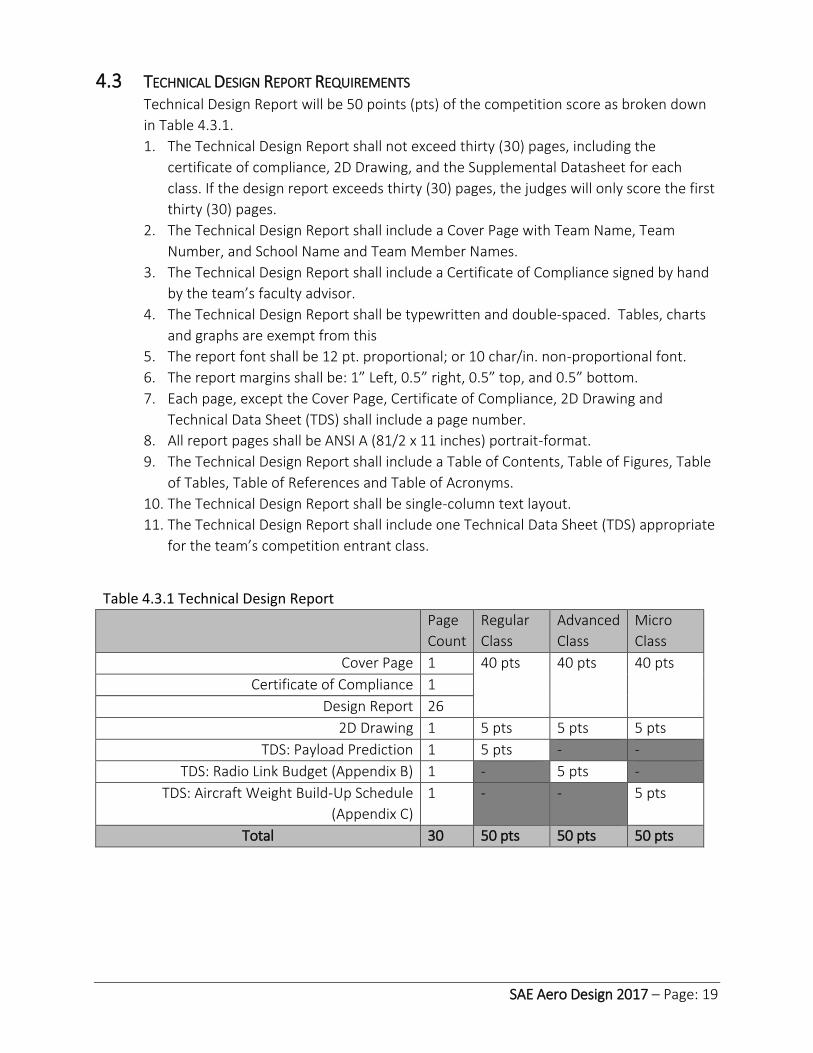
4.3 TECHNICAL DESIGN REPORT REQUIREMENTS Technical Design Report will be 50 points (pts) of the competition score as broken down
in Table 4.3.1.
1. The Technical Design Report shall not exceed thirty (30) pages, including the
certificate of compliance, 2D Drawing, and the Supplemental Datasheet for each
class. If the design report exceeds thirty (30) pages, the judges will only score the first
thirty (30) pages.
2. The Technical Design Report shall include a Cover Page with Team Name, Team
Number, and School Name and Team Member Names.
3. The Technical Design Report shall include a Certificate of Compliance signed by hand
by the team’s faculty advisor.
4. The Technical Design Report shall be typewritten and double-spaced. Tables, charts
and graphs are exempt from this
5. The report font shall be 12 pt. proportional; or 10 char/in. non-proportional font.
6. The report margins shall be: 1” Left, 0.5” right, 0.5” top, and 0.5” bottom.
7. Each page, except the Cover Page, Certificate of Compliance, 2D Drawing and
Technical Data Sheet (TDS) shall include a page number.
8. All report pages shall be ANSI A (81/2 x 11 inches) portrait-format.
9. The Technical Design Report shall include a Table of Contents, Table of Figures, Table
of Tables, Table of References and Table of Acronyms.
10. The Technical Design Report shall be single-column text layout.
11. The Technical Design Report shall include one Technical Data Sheet (TDS) appropriate
for the team’s competition entrant class.
Table 4.3.1 Technical Design Report
Page
Count
Regular
Class
Advanced
Class
Micro
Class
Cover Page 1 40 pts 40 pts 40 pts
Certificate of Compliance 1
Design Report 26
2D Drawing 1 5 pts 5 pts 5 pts
TDS: Payload Prediction 1 5 pts - -
TDS: Radio Link Budget (Appendix B) 1 - 5 pts -
TDS: Aircraft Weight Build-Up Schedule
(Appendix C)
1 - - 5 pts
Total 30 50 pts 50 pts 50 pts

SAE Aero Design 2017 – Page: 20
4.4 2D DRAWING REQUIREMENTS 4. 2D Format and Size
The 2D drawing must be ANSI B sized page (PDF) format (11 x 17 inches). 1. For teams outside North America that cannot submit an ANSI B size drawings, page
format size must be the closest size available to ANSI B. 2. Drawing shall consist of one (1) page.
5. Markings Required
The 2D drawing must be clearly marked with: 1. Team number 2. Team name 3. School name
6. Views Required
Drawings shall include at a minimum, a standard aeronautical 3-view orthographic projection arranged as described: 1. Left side view, in lower left, with nose pointed left. 2. Top view, above and aligned with the left side view, also with nose pointed left (wing-
span break-view permitted). 3. Front view aligned to side view, located in the lower right (projection view non-
standard movement as noted by projection view arrows in accordance with ANSI-Y14.5M 1994).
4. (Regular Class Only) Regular Class shall include an additional view, separate from the basic aircraft, illustrating the passenger cabin layout with appropriate dimensions identifying the passenger seating arrangement. Total passenger capacity shall be labeled.
7. Dimensions Required
Drawing dimensions and tolerance shall be in English units, decimal notation accordance with ANSI-Y14.5M 1994 to an appropriate level of precision to account for construction tolerances (allowable variation from analyzed prediction to account for fabrication) (i.e. X.X = ± .1 in; X.XX = ± .03 in; X.XXX = ± .010 in). The minimum required dimensions/tolerances are: Aircraft length, width, and height
8. Summary Data Required
The drawing shall contain a summary table of pertinent data to include but not limited to:
a. Wingspan
b. Empty weight
c. Battery(s) capacity
d. Motor or engine make and model
e. Motor KV (micro and Regular Class only)
f. Propeller manufacturer, diameter, and pitch

SAE Aero Design 2017 – Page: 21
9. Weight and Balance Information
The 2d drawing shall contain the following weight and balance information: 1. A clearly marked and labeled aircraft datum 2. A weight and balance table containing pertinent aircraft equipment. Each item listed
must show its location from the aircraft datum in inches (the moment arm), the force, and resultant moment. See “Rules and Important Documents” section of the SAE Aero Design website for additional information. The minimum list of pertinent equipment includes: a. Motor or engine b. Battery(s) c. Fuel (advanced class) d. Payload e. Ballast (if used) f. Electronics
3. Center of gravity (CG) locations listed below must be clearly shown on drawing. a. Forward CG limit b. Aft CG limit c. Empty CG location (flightworthy) d. Fully loaded CG (payload and fuel, if applicable)
4.5 TECH DATA SHEET: PAYLOAD PREDICTION (REGULAR CLASS ONLY) Regular Class teams must include a total payload prediction curve as part of the technical
report. The graph represents an engineering estimate of the aircraft’s lift performance
based on density altitude.
1. Graph of payload weight shall be linearized over the relevant range. 2. The linear equation shall be in the form of:
𝑦 = 𝑚𝑋 + 𝑏
Y = Payload weight (lbs.) X = Density Altitude (feet) m = Slope of the linear line b = y-intercept.
3. Only one line and one equation may be presented on the graph. This curve may take into account predicted headwind for local conditions, rolling drag, inertia, engine and propeller performance, or any other factors that may affect takeoff performance. All these factors are allowed components of the prediction curve, but only one curve will be allowed; multiple curves to account for varying headwind conditions will not be allowed.
4. The team must provide a brief explanation of how the line was generated in the body of the report. The section of the report containing this information must be noted on the revenue prediction curve.
5. Graph axes shall be in English units, decimal notation.

SAE Aero Design 2017 – Page: 22
4.6 TECH DATA SHEET: RADIO LINK BUDGET (ADVANCED CLASS ONLY) A link budget is an accounting of all of the gains and losses from the transmitter, through
the medium (free space, cable, waveguide, fiber, etc.) to the receiver in a
telecommunication system. It accounts for the attenuation of the transmitted signal due
to propagation, as well as the antenna gains, feed-line and miscellaneous losses.
Randomly varying channel gains and propagation fading are taken into account by adding
signal margin, depending on the anticipated severity of these effects. The amount of
margin required can be reduced by the use of mitigating techniques such as antenna
diversity or frequency hopping.
A template for the link budget can be found in Appendix B.
4.7 TECH DATA SHEET: WEIGHT BUILDUP (MICRO CLASS ONLY) The Micro Class Weight & Balance Build-up schedule will help teams understand the
importance of managing aircraft weight to achieve safety of flight at the desired payload
fraction. Each team shall supply a one (1) sheet summary list of pertinent aircraft parts
and weight (lb).
A template for the weight buildup can be found in Appendix C.
Payload = -0.001x + 25.2
0
5
10
15
20
25
30
Pay
load
(lb
)
Density Altitude (ft)
Payload Prediction CurveDensity Altitude

SAE Aero Design 2017 – Page: 23
5 TECHNICAL PRESENTATION
Like all professionals, engineers must possess a well-developed ability to synthesize issues and communicate effectively to diverse audiences. The technical portion of the aero-design competition is designed to emphasize the value of an ability to deliver clear, concise and effective oral presentations. Teams can obtain a maximum technical presentation score of fifty (50) points. Presentation score shall be comprised of scores from the presenter’s delivery technique and the judges' evaluation of technical content, empirical analysis, and quality visual aide.
5.1 TECHNICAL PRESENTATION REQUIREMENTS
1. Technical presentation shall last ten (10) minutes and be followed by a five (5) minute "Question and Answer" (Q&A) period.
2. Technical presentation shall be delivered in English.
3. Technical presentation shall address, but are not limited to, trade studies performed, design challenges, and manufacturing techniques.
4. Technical presentation is limited to student team members only. Non-team member pilot, faculty advisors, and/or parents can attend the technical presentation but are prohibited from participating in the setup, delivery, and/or the Q&A.
5. Assistance in the use of visual aids is advisable; Film clips, if used, may not exceed one-minute total duration; Film clips may not be accompanied by recorded narration.
6. Regular and Micro Class shall display their entry aircraft during technical presentation. Advanced Class team are exempted from the requirement to have a static display if and only if the size of the aircraft prevents entry into the room.
7. Advanced Class teams shall make every effort to bring all or a portion of their aircraft to the presentation; however, if the size of the aircraft prevents its display, adequate photographs are acceptable substitutes.
8. During the presentation and static display setup, the teams shall provide a single sheet (8.5” x 11”) marketing/promotion piece to further detail aircraft’s feature, capabilities, and unique design attributes.
5.2 REGULAR CLASS PAYLOAD LOADING AND UNLOADING DEMONSTRATION Technical Presentation for Regular Class shall demonstrate the requirement to quickly
load/secure and unload both Passengers and Luggage. This is a timed activity and shall be
performed by no more than two (2) members of the team within the following time
constraints:
1. One (1) minute to load/secure both Luggage (5 – 7.5lbs.) and 10 passengers for flight. o The demonstration will start with the passengers and cargo separate from the
aircraft and the aircraft in a flight-ready configuration. o The demonstration is considered complete when all required passengers and
Luggage are loaded, secured, and the aircraft is put back in a flight-ready configuration.
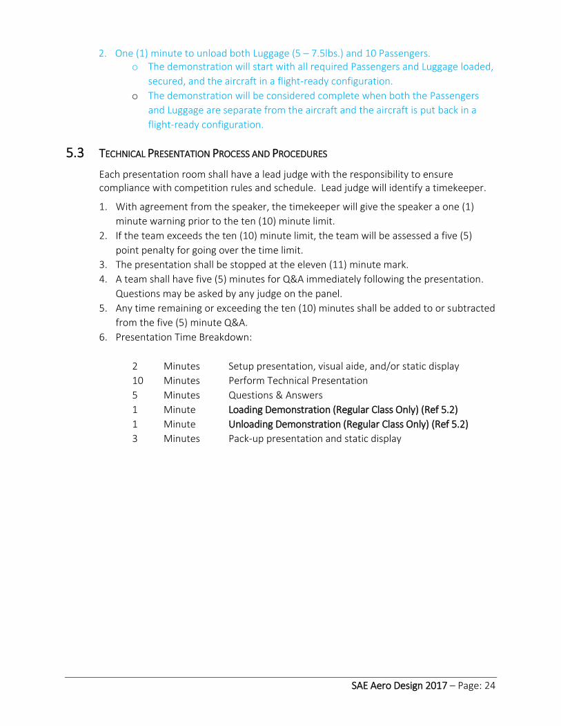
SAE Aero Design 2017 – Page: 24
2. One (1) minute to unload both Luggage (5 – 7.5lbs.) and 10 Passengers. o The demonstration will start with all required Passengers and Luggage loaded,
secured, and the aircraft in a flight-ready configuration.
o The demonstration will be considered complete when both the Passengers
and Luggage are separate from the aircraft and the aircraft is put back in a
flight-ready configuration.
5.3 TECHNICAL PRESENTATION PROCESS AND PROCEDURES
Each presentation room shall have a lead judge with the responsibility to ensure compliance with competition rules and schedule. Lead judge will identify a timekeeper.
1. With agreement from the speaker, the timekeeper will give the speaker a one (1)
minute warning prior to the ten (10) minute limit.
2. If the team exceeds the ten (10) minute limit, the team will be assessed a five (5)
point penalty for going over the time limit.
3. The presentation shall be stopped at the eleven (11) minute mark.
4. A team shall have five (5) minutes for Q&A immediately following the presentation.
Questions may be asked by any judge on the panel.
5. Any time remaining or exceeding the ten (10) minutes shall be added to or subtracted
from the five (5) minute Q&A.
6. Presentation Time Breakdown:
2 Minutes Setup presentation, visual aide, and/or static display
10 Minutes Perform Technical Presentation
5 Minutes Questions & Answers
1 Minute Loading Demonstration (Regular Class Only) (Ref 5.2)
1 Minute Unloading Demonstration (Regular Class Only) (Ref 5.2)
3 Minutes Pack-up presentation and static display

SAE Aero Design 2017 – Page: 25
6 TECHNICAL INSPECTION Technical and Safety inspection of all aircraft will be conducted using the published Technical
and Safety Inspection checklists for each class for the current year. The checklists can be found
on the SAE Aero Design home page under Rules and Important Documents
(http://students.sae.org/cds/aerodesign/rules).
Technical and Safety Inspection is the process of checking all aircraft for:
1 Compliance with all General aircraft requirements.
2 Compliance with all aircraft configuration requirements for their class.
3 Overall safety and airworthiness.
All aircraft must pass the Technical and Safety Inspection in order to compete. It is
strongly suggested that each team pre-inspect their aircraft and correct any problems
using the official inspection checklist before arriving at the competition.
6.1 AIRCRAFT CONFORMANCE TO 2D DRAWING During Technical Inspection, the aircraft will be inspected and measured for conformance
to the 2D drawing presented in the Design Report.
1. At a minimum, aircraft length, wingspan and height dimensions will be measured and
compared to the 2D drawing.
2. All teams must have a hard copy of their design report with them during technical
inspection.
3. Aircraft will have their actual empty CG compared to the empty CG presented in the
design report 2D drawing.
6.2 DEVIATIONS FROM 2D DRAWING Any deviation in construction of the aircraft from the submitted 2D drawing, after
submission of the Design Report, must be reported in writing.
1. Each design change must be documented separately using the Engineering Change
Request (ECR) – a physical copy of which must be brought to the Technical and safety
Inspection
2. Only one design change may be submitted per CR form.
3. Judges will assess penalty points for design changes using the penalty chart.
6.3 FAILURE TO REPORT DESIGN CHANGES Failure to report any design changes incorporated after Design Report submission and
prior to Technical Check-in will incur a one (1) point penalty for each unreported design
change discovered during technical inspection.

SAE Aero Design 2017 – Page: 26
6.4 SAFETY AND AIRWORTHINESS OF AIRCRAFT Technical and Safety Inspection will be also be used to assess the general safety and
airworthiness aspects of each aircraft by seeking any problems that could cause an
aircraft to depart controlled flight. This assessment includes but is not limited to:
1. Unintentional wing warps
2. Control surface alignment
3. Correct control surface response to radio transmitter inputs
4. Structural and mechanical soundness
6.5 INSPECTION OF SPARE AIRCRAFT AND SPARE AIRCRAFT COMPONENTS. 1. All spare aircraft and spare aircraft components (wings, fuselages and tail surfaces)
must be presented for inspection at the same time as the primary aircraft.
2. Any spare aircraft or spare aircraft components presented for inspection after the
team has had their primary aircraft inspected may not be used in the competition.
6.6 AIRCRAFT MUST MEET ALL INSPECTION REQUIREMENTS THROUGHOUT THE COMPETITION. 1. All aircraft must meet all Technical and Safety Inspection requirements throughout
the competition.
2. Any official may request that an aircraft be re-inspected if a general, class
configuration or safety requirement problem is seen on an aircraft at any time during
the event.
3. This includes any errors or omissions made by officials during inspection.
6.7 TECHNICAL AND SAFETY INSPECTION PENALTIES No points are available to be scored as a result of the Technical and Safety Inspection:
teams may only lose points as a result of errors and problems encountered during the
inspection process. Any penalties assessed during Technical Inspection will be applied to
the overall competition score.

SAE Aero Design 2017 – Page: 27
7 REGULAR CLASS DESIGN REQUIREMENTS The objective of Regular Class is to design an aircraft that can generate revenue by carrying as
much payload as possible while observing the power available requirement. Payload will consist
of passengers, represented by tennis balls, and Luggage, represented by payload weights, which
must be carried on each flight. Accurately predicting the lifting capacity of the aircraft and
selecting the appropriate number of passenger seats is an important part of the airplane design.
7.1 AIRCRAFT DIMENSION REQUIREMENT There are no aircraft dimension requirements.
7.2 MATERIAL AND EQUIPMENT RESTRICTIONS FOR REGULAR CLASS 10. Fiber-Reinforced Plastic (FRP)
The use of Fiber-Reinforced Plastic (FRP) is prohibited on all parts of the aircraft.
Exceptions to this rule include: commercially available FRP motor mount, propeller,
landing gear and control linkage components. Exploration of alternative materials is
encouraged.
11. Rubber bands
Elastic material such as rubber bands shall not be used to retain the wing or payloads to
the fuselage.
12. Stability Assistance
All types of gyroscopic or other stability assistance are prohibited.
7.3 AIRCRAFT SYSTEM REQUIREMENTS 13. Electric Motor Requirements
The aircraft shall be propelled by a single electric motor (no multiple motors). There are
no restrictions on the make or model of the electric motor.
14. Gear boxes, Drives, and Shafts
Gearboxes, belt drive systems, and propeller shaft extensions are allowed as long as a
one-to-one propeller to motor RPM is maintained. The prop(s) must rotate at motor
RPM.
15. Aircraft Propulsion System Battery
Regular Class aircraft must be powered by a commercially available Lithium-Polymer
battery pack.
1. Required: 6 cell (22.2 volt) Lithium Polymer (Li-Poly/Li-Po) battery pack.
Minimum requirements for Li-Po battery: 3000 mAh, 25c
2. Homemade batteries are NOT allowed.
16. Power Limiter
All Regular Class aircraft must use a 2015 or 2016 V2 version 1000 watt power limiter
from our supplier, Neumotors.com.
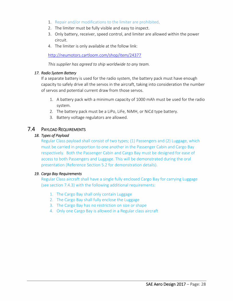
SAE Aero Design 2017 – Page: 28
1. Repair and/or modifications to the limiter are prohibited.
2. The limiter must be fully visible and easy to inspect.
3. Only battery, receiver, speed control, and limiter are allowed within the power
circuit.
4. The limiter is only available at the follow link:
http://neumotors.cartloom.com/shop/item/24377
This supplier has agreed to ship worldwide to any team.
17. Radio System Battery
If a separate battery is used for the radio system, the battery pack must have enough
capacity to safely drive all the servos in the aircraft, taking into consideration the number
of servos and potential current draw from those servos.
1. A battery pack with a minimum capacity of 1000 mAh must be used for the radio
system.
2. The battery pack must be a LiPo, LiFe, NiMH, or NiCd type battery.
3. Battery voltage regulators are allowed.
7.4 PAYLOAD REQUIREMENTS 18. Types of Payload
Regular Class payload shall consist of two types; (1) Passengers and (2) Luggage, which
must be carried in proportion to one another in the Passenger Cabin and Cargo Bay
respectively. Both the Passenger Cabin and Cargo Bay must be designed for ease of
access to both Passengers and Luggage. This will be demonstrated during the oral
presentation (Reference Section 5.2 for demonstration details).
19. Cargo Bay Requirements
Regular Class aircraft shall have a single fully enclosed Cargo Bay for carrying Luggage
(see section 7.4.3) with the following additional requirements:
1. The Cargo Bay shall only contain Luggage 2. The Cargo Bay shall fully enclose the Luggage 3. The Cargo Bay has no restriction on size or shape 4. Only one Cargo Bay is allowed in a Regular class aircraft

SAE Aero Design 2017 – Page: 29
20. Luggage and Luggage Support Requirements
Luggage shall consist of a support assembly and payload plates with the following
additional requirements:
1. For weight measurement and scoring, Luggage shall consist of the payload plates and support structure used to retain the weight(s) in the Cargo Bay.
2. An average Luggage weight of ½ lb. or more must be carried for each Passenger carried.
3. If the Luggage weight carried does not meet the ½ lb. per passenger requirement, the excess Passengers will be counted as empty seats and the flight scored accordingly.
4. Luggage weight in excess of ¾ lbs. per passenger will not count in Luggage weight scoring.
5. Luggage must be secured to the airframe, within the Cargo Bay, to ensure the payload will not shift or come loose in flight.
6. There is no required configuration for the payload plates or support assembly. 7. Teams must provide their own payload plates. 8. The support assembly must be constructed so as to mechanically retain the
payload plates as a homogeneous mass. The design of the support assembly will depend upon the configuration of the payload plates.
9. Tape, Velcro, rubber bands and friction systems alone may not be used to retain the support assembly and/or payload plates.
21. Passenger Payload Definition
The Passenger* payload must consist only of unmodified tennis balls which meet or
exceed the minimum size and weight specifications for Type 1 and Type 2 tennis balls as
specified by the International Tennis Federation (ITF). Accordingly, the minimum tennis
ball weight is 1.975 ounces (56 grams) and minimum ball diameter allowed is 2.57 inches
(5.64 centimeters). A list of accepted brands of tennis balls is given at
http://www.itftennis.com/technical/balls/.
* Teams must provide their own Passengers.
22. Passenger Cabin Requirements
Regular Class aircraft must position all Passengers in a single Passenger Cabin.
1. The Passenger Cabin must position all Passengers to be tangent to the same side of a single geometric plane.
2. All Passengers must be constrained to the geometric plane within the Passenger Bay so that they will not shift or come loose during any portion of a flight.
3. A position designed to hold a Passenger is a Seat. Passenger Seats must be in contiguous positions. Contiguous is defined as being less than 0.25in from the adjacent Passenger.
4. Any Passenger not in a seat after a flight will not count as revenue generated by Passengers.
5. Passengers must be in a countable configuration to be scored as a revenue generating Passenger. A countable configuration is defined as when Passengers are clearly visible and can be easily touch-counted.

SAE Aero Design 2017 – Page: 30
6. Each Passenger carried in excess of the maximum number (as determined by Luggage weight), will not count as a revenue generating Passenger and will be scored as an empty Seat.
7.5 REGULAR CLASS SCORING In order to participate in the flight portion of the competition, each team is required to
have submitted AND received a score for their Design Report and Oral Presentation.
The Final Regular Class Flight Score shall be based upon the Total Revenue earned and
Total Penalty deductions received.
𝐹𝐹𝑆 = 𝐹𝑖𝑛𝑎𝑙 𝐹𝑙𝑖𝑔ℎ𝑡 𝑆𝑐𝑜𝑟𝑒 = 1
40 𝑁[∑ 𝐹𝑆
𝑁
1
] − ∑ 𝑇
N = Total Number of Flight Rounds During Competition
Flight Score
𝐹𝑆 = $100𝑃 + $50𝐶 − $100𝐸 𝑓𝑜𝑟 𝑒𝑎𝑐ℎ 𝑓𝑙𝑖𝑔ℎ𝑡
𝑃 = 𝑁𝑢𝑚𝑏𝑒𝑟 𝑜𝑓 𝑠𝑒𝑎𝑡𝑒𝑑 𝑃𝑎𝑠𝑠𝑒𝑛𝑔𝑒𝑟𝑠 𝑐𝑎𝑟𝑟𝑖𝑒𝑑 𝑜𝑛 𝑎 𝑓𝑙𝑖𝑔ℎ𝑡
𝐶 = 𝐿𝑢𝑔𝑔𝑎𝑔𝑒 𝑤𝑒𝑖𝑔ℎ𝑡 (𝑙𝑏𝑠)
𝐸 = 𝑁𝑢𝑚𝑏𝑒𝑟 𝑜𝑓 𝑒𝑚𝑝𝑡𝑦 𝑆𝑒𝑎𝑡𝑠
All Flight Score’s with a value less than zero (0) will default to zero (0).
Total Penalty Points
𝑇 = 𝑃𝑒𝑛𝑎𝑡𝑦 𝑃𝑜𝑖𝑛𝑡𝑠 𝑎𝑠𝑠𝑒𝑠𝑠𝑒𝑑 𝑡ℎ𝑜𝑢𝑔ℎ𝑜𝑢𝑡 𝑡ℎ𝑒 𝑒𝑣𝑒𝑛𝑡
SAE Aero Design 2017 – Page: 31
8 ADVANCED CLASS DESIGN REQUIREMENTS The objective of the Advanced Class is to design the most efficient aircraft capable of accurately
dropping multiple two pound (2 lb.) humanitarian aid packages from a minimum of 100ft above
ground level. Though the class is mostly focused on mission success, students will need to
perform trade studies to optimize empty weight and anticipate repair build-up weight while
meeting several aircraft design requirements.
8.1 VIDEO DOCUMENTATION OF PROVEN OPERATIONAL ABILITY FOR ADVANCED CLASS All Advanced class teams are required to bring a video documenting the proven operational ability of their advanced class aircraft to Technical and Safety Inspection. 1. The video must show the following three activities accomplished successfully with
their competition aircraft: A takeoff, a payload release, and a landing without damage.
2. The video will be reviewed by SAE officials during Technical and Safety Inspection. 3. Advanced class aircraft will not be allowed to compete without the video
documentation of proven operational ability. 4. Teams must provide a device to play the video for the officials at a screen size that
allows the officials to clearly see the aircraft accomplish each required activity. 5. Videos should be no more than 1 minute in length. Edited video will be accepted if
the video is of the same flight.
8.2 AIRCRAFT DIMENSION REQUIREMENT There are no dimensional limits on an Advanced Class Aircraft.
8.3 ENGINE REQUIREMENTS Advanced Class aircraft must be solely powered by internal combustion, reciprocating engines. The common-use displacement will be used to determine displacement, i.e. the advertised displacement. 1. The total displacement may not exceed .46 cubic inches. 2. Advanced Class aircraft are not limited to the number of engines. 3. No changes to the internal displacement of the engine(s) will be allowed. 4. No restriction to the make and model of the engine(s).
8.4 RADIO SYSTEM BATTERY The radio system battery pack must have enough capacity to safely drive all the servos in the aircraft, taking into consideration the number of servos and potential current draw from those servos. If the radio system battery also supplies DAS and FPV power needs, the radio system battery must be large enough for these power requirements as well. 1. A battery pack with a minimum capacity of 1000 mAh must be used for the radio
system. 2. The battery pack must be a LiPo, LiFe, NiMH, or NiCd type battery. 3. Battery voltage regulators are allowed.
SAE Aero Design 2017 – Page: 32
8.5 RUBBER BANDS Rubber bands shall not be used to retain the wing to the fuselage.
8.6 PAYLOAD REQUIREMENTS Advanced Class payload requirements shall consist of two types of payload.
Releasable payload
Static payload
23. Releasable Payload Requirements
There is no limit to the number of Releasable Payloads that can be carried by each
aircraft. The following requirements apply to releasable payload:
1. Releasable Payloads may be mounted internally and/or externally to the airframe.
2. Releasable Payloads shall be independent of all others carried on the aircraft.
3. Releasable Payloads that are connected (e.g., become tangled during drop) in any
way shall not be counted for score.
4. Each Releasable Payload shall be sand enclosed within a sewn woven fabric
material container. Placing the sand inside a thin plastic bag inside the woven
fabric is allowed.
5. Each Releasable Payload shall have a minimum weight of 2.0 lbs. and a maximum
weight of 2.25 lbs.
6. Each Releasable Payload will be inspected and weighed during technical
inspection and after each successful flight.
7. Excluding the streamer, each Releasable Payload shall be no more than 10 inches
in any linear dimension (length, width or height).
8. The CG of each mounted Releasable Payload shall not exceed a distance of 6
inches laterally or longitudinally from the CG of the EW aircraft. This shall be
measured during technical inspection.
9. Static payload bay(s) must be completely closed off and physically separated from
all releasable payload.
10. Each Releasable Payload shall have one (1) flexible streamer attached to facilitate
payload location and recovery.
11. Streamers shall be colored such that they are highly visible against typical terrain.
12. Each streamer shall be 54 ± 6 inches long and 2.5 ± 0.5 inches wide. Spot check of
streamer dimensions will be performed as required. If the streamer does not
meet the dimensional requirements, the releasable payload score will be zeroed
(0) for that flight attempt.
13. Streamers must be in a stored configuration prior to the drop and deploy before
each releasable payload strikes the ground.
14. Streamers must remain attached to each releasable payload at all times. Attached
is defined as being able to support the weight of the releasable payload.
15. Releasable payload shall be marked with the team number in three places, on the
container, and both ends of the streamer with numbers 2-inches in height.

SAE Aero Design 2017 – Page: 33
24. Static Payload Requirements
1. Static payload shall be in its own payload bay(s).
2. Static payload bay(s) shall be fully enclosed.
3. Static payload bay(s) shall have no restriction on size or shape.
4. Advanced Class may have multiple Static Payload bays.
8.7 GYROSCOPIC AND OTHER STABILITY AUGMENTATION Gyroscopic assist or other forms of stability augmentation are allowed in Advanced Class.
8.8 AUTONOMOUS FLIGHT Autonomous flight systems that cause the aircraft to navigate without direct pilot control
input are prohibited.
8.9 DATA ACQUISITION SYSTEM (DAS) Advanced Class aircraft must have a Data Acquisition System (DAS) that shall record
altitude.
1. Using a ground receiver station, the team must display the real-time altitude of the
aircraft to the Payload Specialist and the flight judge.
2. Team must automatically record the altitude of the aircraft at the moment they
initiate the release of any Releasable Payload.
3. The DAS recording must be performed on the ground station and must support play
back for review on demand.
4. Altitude must be measured in feet with display precision of at least one (1) ft.
5. DAS system must use a discrete and removable Red arming plug to apply power to
the DAS system. The DAS arming plug must be located on top of the aircraft at least
12 inches from the propeller. One Red arming plug can be used for both DAS and FPV.
6. DAS equipment may also have a reset switch, if desired. If a manual reset switch is
used, it must be located externally at least 12 inches away from the propeller. A
wireless DAS reset system is allowed.
7. DAS systems shall not use the same 2.4 GHz channel as the flight control system,
unless the telemetry being used is part of the radio control system being used. A DAS
built into the radio control system must meet all DAS rules requirements.
8.10 FIRST PERSON VIEW SYSTEM (FPV) Some type of First Person View (FPV) system is required to be used as a drop sighting
device. FPV video and the required telemetry data for altitude must be transmitted to the
ground station and be visible to the Payload Specialist and the flight judge.
1. Payload Specialist must be a team member and must use the FPV video stream to
verbally direct the pilot to the drop zone.
2. The primary pilot must fly visually only (no FPV goggles or ground station reference).
3. The FPV system must transmit a live real time video signal from the aircraft to the
ground station. FPV and DAS data may be combined on the ground station display.

SAE Aero Design 2017 – Page: 34
4. FPV systems CANNOT use the same frequency as the flight control system. Use of 2.4
GHz for FPV video is prohibited.
5. The FPV system must use a discrete and removable Red arming plug to apply power
to the FPV system. The Red arming plug must be located on top of the aircraft at least
12” from the propeller. One Red arming plug can be used for both DAS and FPV.
8.11 DAS AND FPV FAILURES Any DAS or FPV failure during the flight attempt is considered a missed flight attempt and
receives no points.
Example: A team has flown four (4) rounds successfully and on the 5th round the
aircraft takes-off successfully, makes a successful drop, but the DAS altitude reading
malfunctions. The flight attempt will NOT be considered a qualified flight and the
team will receive zero (0) flight score for round 5.
Advanced class aircraft must have functioning DAS altitude readout and FPV to be
allowed to take off for an official flight.
8.12 PAYLOAD SPECIALIST Advanced class aircraft must be able to drop the Releasable payload using a system
commanded by the Payload Specialist.
1. The primary pilot cannot have access to or activate the Releasable Payload.
2. The Payload release must be manually activated by the Payload Specialist or by an
automatic release system that is part of the aircraft electronics.
3. If an automatic Payload release system is used, it must have a manual override
controlled by the payload specialist.
4. The Releasable Payload release cannot be controlled from or connected to the
primary pilot’s R/C transmitter in any way.
5. Teams may activate the payload release system using a second 2.4 GHz radio system
or some other method based on their DAS or telemetry system.
8.13 LINK BUDGET FORMAT FOR SAE AERO DESIGN COMPETITION Radio Link Budget should be used to establish the requirements for the advanced class FPV and DAS systems. Each system component needs to be described with enough detail to evaluate its effect on system performance. The link budget form provided in the rules appendix is required to summarize the system parameters in the design report. Calculations for the 2.4GHz radio control systems are optional. Calculations for the FPV and DAS systems are required. An example link budget form can be found in Appendix B.

SAE Aero Design 2017 – Page: 35
8.14 FLIGHT & DROP PROCEDURES
1. Teams are allowed two drop attempts on the target. Teams may drop as many or as
few releasable payloads as they wish during each drop attempt.
2. Advanced Class teams are allowed to drop their releasable cargo in the upwind or
downwind directions or both.
3. Dropping direction shall be declared to the Air Boss prior to takeoff and adhered to
during flight operations. Stated direction will be recorded on the flight log.
4. To receive a flight score, the team shall release at least one successful payload.
A successful payload release is defined as the intentional targeted drop of at least one
releasable payload, at 100ft above the target, in the dropping direction indicated to the
flight boss prior to takeoff. The payload does not have to land in the target zone but must
meet all requirements after the drop. Altitude at release must be successfully recorded on
the DAS and displayed on the ground station.
Example 1:
A team states they will drop in one direction (upwind or downwind). They will get
two attempts to position their aircraft in the proper direction. Each approach to
the drop zone in the declared direction will be counted as a drop attempt.
Example 2:
A team states they will drop in both directions; upwind and downwind. Any
approach to the drop zone is considered an attempt.

SAE Aero Design 2017 – Page: 36
8.15 ADVANCE CLASS SCORING In order to participate in the flight portion of the competition, each team is required to
have submitted AND received a score for both Design Report and Oral Presentation. In
addition, each team must have provided video demonstration of aircraft operational
ability to SAE officials during Technical and Safety Inspection.
25. Zone Multiplier
The Zone Multiplier (Zm) is the multiplier earned for each releasable payload successfully
dropped in the respective drop zone.
Zone Range Multiplier
1 0 ft 15 ft 1.00
2 15 ft 30 ft 0.75
3 30 ft 45 ft 0.50
4 45ft 60 ft 0.25
OUTSIDE 60 ft + 0.00
26. Scoring Equation
𝐹𝑖𝑛𝑎𝑙 𝐹𝑙𝑖𝑔ℎ𝑡 𝑆𝑐𝑜𝑟𝑒 = 4 × (1
𝑁∑ 𝐹𝑆
𝑁
0
) − ∑ 𝑇
Where:
𝐹𝑆 = 𝐹𝑙𝑖𝑔ℎ𝑡 𝑆𝑐𝑜𝑟𝑒 = 𝑆𝑝 + (𝑆𝑝 × ∑ 𝑍𝑚)
𝑍𝑚 = 𝑍𝑜𝑛𝑒 𝑀𝑢𝑙𝑡𝑖𝑝𝑙𝑖𝑒𝑟
𝑆𝑝 = 𝑆𝑡𝑎𝑡𝑖𝑐 𝑃𝑎𝑦𝑙𝑜𝑎𝑑 (𝑙𝑏𝑠)
𝑇 = 𝑇𝑜𝑡𝑎𝑙 𝑃𝑒𝑛𝑎𝑙𝑡𝑦 𝑃𝑜𝑖𝑛𝑡 𝐴𝑠𝑠𝑒𝑠𝑠𝑒𝑑 𝑡ℎ𝑟𝑜𝑢𝑔ℎ𝑜𝑢𝑡 𝑡ℎ𝑒 𝑐𝑜𝑚𝑝𝑒𝑡𝑖𝑡𝑖𝑜𝑛
𝑁 = 𝑇𝑜𝑡𝑎𝑙 𝑁𝑢𝑚𝑏𝑒𝑟 𝑜𝑓 𝐹𝑙𝑖𝑔ℎ𝑡 𝑅𝑜𝑢𝑛𝑑𝑠 𝐷𝑢𝑟𝑖𝑛𝑔 𝐶𝑜𝑚𝑝𝑒𝑡𝑖𝑡𝑖𝑜𝑛
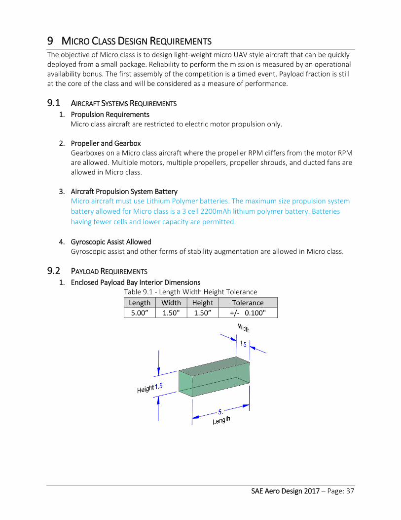
SAE Aero Design 2017 – Page: 37
9 MICRO CLASS DESIGN REQUIREMENTS The objective of Micro class is to design light-weight micro UAV style aircraft that can be quickly deployed from a small package. Reliability to perform the mission is measured by an operational availability bonus. The first assembly of the competition is a timed event. Payload fraction is still at the core of the class and will be considered as a measure of performance.
9.1 AIRCRAFT SYSTEMS REQUIREMENTS 1. Propulsion Requirements
Micro class aircraft are restricted to electric motor propulsion only.
2. Propeller and Gearbox Gearboxes on a Micro class aircraft where the propeller RPM differs from the motor RPM are allowed. Multiple motors, multiple propellers, propeller shrouds, and ducted fans are allowed in Micro class.
3. Aircraft Propulsion System Battery Micro aircraft must use Lithium Polymer batteries. The maximum size propulsion system
battery allowed for Micro class is a 3 cell 2200mAh lithium polymer battery. Batteries
having fewer cells and lower capacity are permitted.
4. Gyroscopic Assist Allowed
Gyroscopic assist and other forms of stability augmentation are allowed in Micro class.
9.2 PAYLOAD REQUIREMENTS 1. Enclosed Payload Bay Interior Dimensions
Table 9.1 - Length Width Height Tolerance
Length Width Height Tolerance
5.00” 1.50" 1.50” +/- 0.100"
SAE Aero Design 2017 – Page: 38
2. Payload Bay Requirements Micro class aircraft must have a single fully enclosed payload bay with precision interior
dimensional requirements.
1. A fully enclosed payload bay is defined as having four sides, a bottom and a top. 2. The payload bay must be fully enclosed within the aircraft and meet the precision
dimension requirements above. (Table 9.1) 3. One or more surfaces of the payload bay must be removable for payload access and
for inserting the official payload bay test block. 4. The interior surfaces of the payload bay must be smooth and unbroken (no lightening
holes or visible gaps in and between surfaces). 5. The payload bay position may be adjusted forward and aft as needed. 6. No penetrations are allowed through the payload bay surfaces except for the payload
support assembly. 7. The payload support assembly MUST be removable so that the payload bay test block
can be inserted into the payload bay during technical inspection. 8. The removable payload support assembly will be considered as payload. 9. The payload bay is not considered as payload.
10. All payload carried for score must be carried within the payload bay.
3. Payload and Payload Supports
The payload must consist of a support assembly and payload plates. The payload must be secured to the airframe to ensure the payload will not shift or come loose in flight. 1. There is no required configuration for the payload plates. 2. Teams must provide their own payload plates. 3. The support assembly must be constructed so as to retain the weights as a
homogeneous mass. The design of the support assembly will depend upon the configuration of the payload plates.
4. The total payload consists of the payload plates plus the support assembly.
9.3 MICRO CLASS AIRCRAFT LAUNCH 1. Hand launched (tossed)
The Micro class aircraft must be hand launched (tossed) by throwing the aircraft using one (1) hand grasping the aircraft. a. Only one (1) member of the team can enter pre-marked launch zone. b. The pilot must be outside the pre-marked launch zone during the tossing action. c. The aircraft can only be tossed by one (1) team member. d. The aircraft cannot be tossed by the pilot. e. There is no limit on number of steps taken during the launching action, but the
person must remain inside the launch zone before and after releasing the aircraft.
2. Hand launched (tossed) violations
The following actions are not permitted and will invalidate the flight attempt and score for the round.
a. Using more than one hand to toss the aircraft b. Tossing the aircraft from any other part of the aircraft other than the fuselage

SAE Aero Design 2017 – Page: 39
c. Running with the aircraft during launch d. Pilot launching (tossing) the aircraft
9.4 MICRO CLASS AIRCRAFT HAND-LAUNCH SAFETY REQUIREMENTS 1. Safety Gear
Safety gear must be used by the designated team member performing the aircraft toss and any team member assisting with preparing the aircraft inside the launch zone. Safety gear will consist of:
a. Safety glasses b. Hard hat
9.5 AIRCRAFT SYSTEM CONTAINER 1. Storage and Transport Container
Micro class aircraft must fit in a storage and transport container with size limitations. The required container may be either purchased or constructed. Compliance with the following requirements will be confirmed during technical inspection.
a. The aircraft container maximum outside diameter must measure no more than 6” b. The fully packed aircraft container must weigh no more than 10 pounds (lbs). c. The aircraft container must include a shoulder strap and a carrying handle. The
strap and handle are not considered as part of the container’s maximum outside diameter of 6”.
d. The container must be one-man portable. e. The aircraft container must have school name, team name and team number on
the outside surface of the container.
2. Aircraft System Packaging General Requirements
The aircraft system container must contain the following: a. All components of the flight ready aircraft including airframe, propulsion system
battery, payload assembly, payload plates and any other part(s) required for flight must be packaged within the constraints of the aircraft system container.
b. The propulsion system battery must not be pre-installed in the aircraft. c. The red arming plug must not be pre-installed in the aircraft. d. The propulsion system battery must be contained in its own partitioned space in
the aircraft system container. e. The transmitter and any spare parts are not required to be in the aircraft system
container. f. If the aircraft uses a separate radio system battery, it may be pre-installed in its
flight location. If the aircraft uses a radio system battery and a team elects not to pre-install it, then the radio system battery must be contained within its own partitioned space within the aircraft system container.

SAE Aero Design 2017 – Page: 40
9.6 TIMED AIRCRAFT ASSEMBLY 1. Assembly Demonstration Bonus (Round 1 Only)
Assembly demonstration must consist of installation of the propulsion system battery at minimum. The timed Micro class assembly demonstration for Round 1 is optional. If a team elects to perform the demonstration, the Micro class aircraft must be assembled within the specified time-constraint in order to receive an assembly demonstration bonus. Aircraft assembly will be timed and scored during ROUND 1 only. The assembly demonstration bonus (Bad) will be calculated per section 9.8.
a. The timed assembly demonstration can ONLY be performed during Round 1. b. If the aircraft is not assembled within the specified time, the assembly
demonstration bonus will be zeroed, and the team will have the option to move to the back of the line, finish assembly, and attempt a Round 1 flight.
c. The assembly demonstration is considered complete when all tasks required for flight have been performed with the exception of:
1. Installing the Red Arming Plug 2. Performing preflight controls checks 3. Hand launching the Micro class aircraft
d. Performing preflight controls checks is limited to validation of adequate control
movements and range. Disassembling the aircraft during the pre-flight control checks will invalidate the Aircraft Demonstration Bonus.
e. Teams may elect not to perform the assembly demonstration. If this is the case, there are no timed assembly requirements. The aircraft must be assembled but not armed prior to entering the launch zone. Micro class aircraft must be airborne within the specified time constraints in accordance with Section 3.5.
f. For Round 2 thru Round n: there are no timed assembly requirements. The
aircraft must be assembled but not armed prior to entering the launch zone. Micro class aircraft must be airborne within the specified time constraints in accordance with Section 3.5.
g. The Assembly Demonstration Bonus is only applicable if the ensuing flight is
successful. A failed flight attempt in Round 1 will result in a zero Assembly Demonstration Bonus.
Note: Round 1 is defined as the first round on the first day of the competition, not the team’s first attempt to fly at the competition.

SAE Aero Design 2017 – Page: 41
9.7 MISSION REQUIREMENTS 1. Process for Assembly Demonstration Bonus
a. Two team members tasked with assembling the aircraft will be located immediately outside the launch circle in a designated area. At this time, the fully packaged, non-energized aircraft, with flight battery NOT installed, must be held over the shoulder using the required shoulder strap. (Failure to have the Red Arming Plug removed at this time will result in a zero bonus and a disqualified flight.)
b. The head judge give a “Go” command to begin assembly. Two scoring officials will start the time.
c. When the aircraft is fully assembled, with the flight battery installed, the team will give the “DONE” command to signal the timers to stop the timer.
d. After the “DONE” command is given by the assembling team, no further assembly may continue.
e. The official will inspect the aircraft to confirm aircraft flight ready status and record the time in seconds.
f. Head judge will give the instruction to install the Red Arming Plug. (Any further assembly of the aircraft after the clock has stopped will result in zero for the bonus.)
g. The team will then step into the launch circle to begin their flight attempt. At this time, upon signal given by the Air Boss, a team will have 60 seconds (1.5 minutes) to accomplish a successful launch. During these 60 seconds, the pilot can do a final test on the controls. If the officials witness additional assembly after the clock has stopped, the assembly demonstration bonus will be zeroed.
2. Time Limit for Aircraft Launch
Micro class aircraft should be assembled prior to entering the launch zone. a. Each team will have 60 seconds to complete preflight checks, energize the
propulsion system, and check the controls and hand-launch the aircraft. b. Only one takeoff launch attempt is permitted per round.
3. Aircraft Takeoff and Circuit
Takeoff for Micro class is defined as the point at which the aircraft departs the hand of the person throwing the aircraft. Once takeoff occurs, Micro Class aircraft are required to: a. Remain airborne and fly past the designated turn point before turning
approximately 180 degrees in heading. b. Flying past a second designated turn point, turning 180 degrees in heading. c. Land in the designated landing zone for Micro class (see figure below). d. Takeoff direction will be determined by the Air Boss, and normally selected to
face into the wind.

SAE Aero Design 2017 – Page: 42
9.8 MICRO CLASS FLIGHT SCORING Final Flight Score will be calculated in three parts: the average of successful flight round
scores; the summation of operational availability bonus points; and the Round 1 timed
assembly bonus score. This running calculation will be posted on the score board to
determine team standings.
𝐹𝐹𝑆 = 𝐹𝑖𝑛𝑎𝑙 𝐹𝑙𝑖𝑔ℎ𝑡 𝑆𝑐𝑜𝑟𝑒 = (1
𝑆∑ 𝐹𝑆𝑛
𝑆
1
) + (∑ 𝐵𝑜𝑎
𝑆
1
) + (𝐵𝑎𝑑) − ∑ 𝑇
Where:
Flight Score:
𝐹𝑆𝑛 = (70 − 𝐿𝑎𝑐) × (2 × 𝑃𝐹)
Bonus for Operational Availability
𝐵𝑜𝑎 = (5 × 𝑃𝐹)
Payload Fraction
𝑃𝐹 = 𝑃𝑎𝑦𝑙𝑜𝑎𝑑 𝐹𝑟𝑎𝑐𝑡𝑖𝑜𝑛 = (𝑊𝑝𝑎𝑦𝑙𝑜𝑎𝑑)
(𝑊𝑝𝑎𝑦𝑙𝑜𝑎𝑑 + 𝑊𝑒𝑚𝑝𝑡𝑦)
Bonus for assembly demonstration
𝐵𝑎𝑑 = (15 − 0.1𝑡)
𝐿𝑎𝑐 = 𝐿𝑒𝑛𝑔𝑡ℎ 𝑜𝑓 𝐴𝑖𝑟𝑐𝑟𝑎𝑓𝑡 𝐶𝑜𝑛𝑡𝑎𝑖𝑛𝑒𝑟
𝑡 = 𝑡𝑖𝑚𝑒 𝑟𝑒𝑐𝑜𝑟𝑑𝑒𝑑 𝑖𝑛 𝑠𝑒𝑐𝑜𝑛𝑑𝑠
𝑆 = 𝑡𝑜𝑡𝑎𝑙 𝑛𝑢𝑚𝑏𝑒𝑟 𝑜𝑓 𝑠𝑢𝑐𝑐𝑒𝑠𝑠𝑓𝑢𝑙 𝑟𝑜𝑢𝑛𝑑𝑠 𝑓𝑙𝑜𝑤𝑛
𝑇 = 𝑇𝑜𝑡𝑎𝑙 𝑃𝑒𝑛𝑎𝑙𝑡𝑦 𝑎𝑐𝑟𝑢𝑒𝑑 𝑡ℎ𝑟𝑜𝑢𝑔ℎ𝑜𝑢𝑡 𝑡ℎ𝑒 𝑐𝑜𝑚𝑝𝑒𝑡𝑖𝑡𝑖𝑜𝑛

SAE Aero Design 2017 – Page: 43
10 FUTURE RULE CHANGES This section is intended to give teams advance notice of possible future changes to SAE Aero
Design rules. These changes might have a significant effect on the design of the aircraft. This is
an informational notice only and does not imply that the proposed changes will in fact be
adopted.
One of the new metrics the rules committee is considering for the Micro class is to measure
endurance. This may be incorporated in future Micro-Class Competition.
The use of lock washers and nylon locking nuts are already popular and in use in the RC
hobby may be included in future competitions.
Possible advanced class engine change from internal combustion to an all-electric class.
Eliminating flight rounds.

SAE Aero Design 2017 – Page: 1
APPENDIX A
SAE AERO DESIGN
STATEMENT OF COMPLIANCE Certification of Qualification
Team Name Team Number
School
Faculty Advisor
Faculty Advisor’s Email
Statement of Compliance
As Faculty Advisor, I certify that the registered team members are enrolled in collegiate courses.
This team has designed, constructed and/or modified the radio controlled aircraft they will use for
the SAE Aero Design 2017 competition, without direct assistance from professional engineers, R/C
model experts or pilots, or related professionals.
Signature of Faculty Advisor
Team Captain Information:
Team Captain:
Captain's E-mail:
Captain’s Phone:
Note:
A copy of this statement needs to be included in your Design Report as page 2 (Reference Section
4.3)

SAE Aero Design 2017 – Page: 2
APPENDIX B
Advanced Class Tech-Data Sheet: Radio Link Budget Supply data for each radio system used onboard aircraft. Expand number of columns as needed.
Calculations for Radio control systems using 2.4GHz are optional.
Radio System Function (FPV, DAS, RC, Payload) Units FPV DAS RC Payload
Release Operating Frequency, F MHz Wavelength (WL) = 300 / F (MHz) meters Maximum Operating Range (Rng) meters Free Space Path Loss (Lfs) = 20Log(4Pi (Rng / WL)) dB Transmitter Brand/Model Transmitter Power (Pt) dBm Number of Transmitter Channels --- Transmit Antenna Gain (Gt) dB Transmit Antenna Polarization (H, V, RHC, LHC) Transmit Losses (Lt) dB Receive Losses (Lr) dB Receive Antenna Gain (Gr) dB Transmit Antenna Polarization (H, V, RHC, LHC) Processing Gain (Gpr) dB Polarization Loss (Lpol) dB Power Rcvd (Pr) = Pt + Gt + Gr + Gpr – Lfs – Lt – Lr – Lpol dBm Receiver Signal Power Required Pmin. dBm Signal Margin = Pr – Pmin dB
FPV Transmitter Operating Frequencies Available (MHz).
If your video transmitter or data-link is set to a fixed frequency which can be changed with a
switch, please list the available frequencies to aid the event in reducing frequency conflicts. If
your system is spread spectrum, list the range of frequencies on which it can operate.
Reference: https://en.Wikipedia.org/wiki/Link_budget
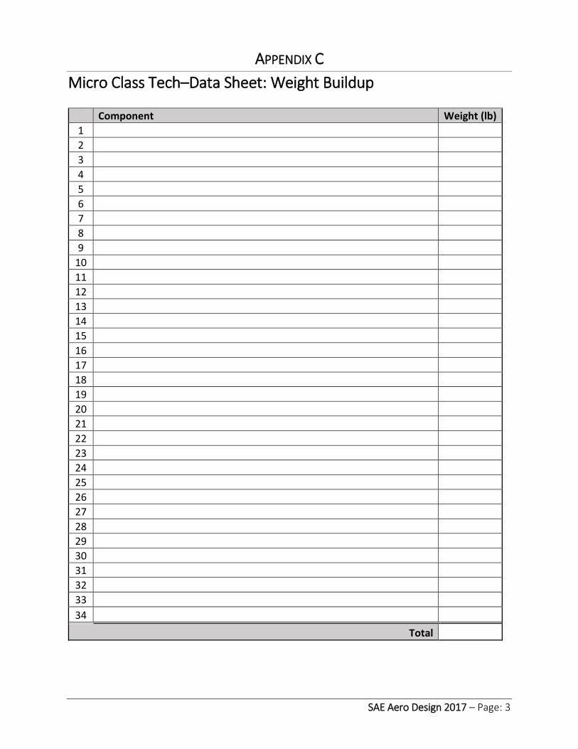
SAE Aero Design 2017 – Page: 3
APPENDIX C
Micro Class Tech–Data Sheet: Weight Buildup
Component Weight (lb)
1
2
3
4
5
6
7
8
9
10
11
12
13
14
15
16
17
18
19
20
21
22
23
24
25
26
27
28
29
30
31
32
33
34
Total

SAE Aero Design 2017 – Page: 4
APPENDIX D
Engineering Change Request (ECR) Team Number:
School Name:
Team Name:
Discovery
Method
☐Tech
Inspection
☐Safety
Inspection
☐Test Flight
☐Design
Analysis
System
Affected ☐Wing (area
+/-)
☐Fuselage
(area +/-)
☐Horiz.
Stabilizer
(area +/-)
☐Vertical Tail
(area +/-)
☐Engine
Mount
assembly
☐Mechanical
☐Landing System
☐Structural
☐Electronics (avionics)
☐Payload bay Assembly
Surface Area
AREA ADDED:___________ AREA REDUCED:_____________
If surface area was impacted by the modification, specify total area added or reduced. Show
calculations:
Describe the
Modification
Reason for
Modification
Other
Considerations
*** OFFICIAL USE ONLY ***
ECR #

SAE Aero Design 2017 – Page: 5
Penalty Chart Guidelines
Aero-Dynamic Changes
Plan Form Area Points Structural Change
(Pts Deducted)
Mechanical
(Pts Deducted)
Electronic
(Pts Deducted)
Misc
(Pts Deducted) Add (in2) Removed
(in2) Add Removed
1 1 .5 4 3 3 2
2 1 .5 4 3 3 2
3 1 .5 4 3 3 2
4 1 .5 4 3 3 2
5 1 .5 4 3 3 2
6 2 1 4 3 3 2
7 2 1 4 3 3 2
8 2 1 4 3 3 2
9 2 1 4 3 3 2
10 4 2 4 3 3 2
11 4 2 4 3 3 2
12 4 2 4 3 3 2
13 4 2 4 3 3 2
14 4 2 4 3 3 2
15 6 3 4 3 3 2
16 6 3 4 3 3 2
17 6 3 4 3 3 2
18 6 3 4 3 3 2
19 6 3 4 3 3 2
20 8 4 4 3 3 2
21 8 4 4 3 3 2
22 8 4 4 3 3 2
23 8 4 4 3 3 2
24 8 4 4 3 3 2
25 10 5 4 3 3 2
26 10 5 4 3 3 2
27 10 5 4 3 3 2
28 10 5 4 3 3 2
29 10 5 4 3 3 2
30 12 6 4 3 3 2
31 12 6 4 3 3 2
32 12 6 4 3 3 2
33 12 6 4 3 3 2
34 12 6 4 3 3 2
35 14 7 4 3 3 2
36 14 7 4 3 3 2
37 14 7 4 3 3 2
38 14 7 4 3 3 2
39 14 7 4 3 3 2
40+ 14 7 4 3 3 2
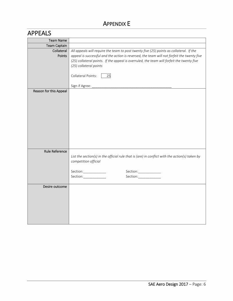
SAE Aero Design 2017 – Page: 6
APPENDIX E
APPEALS Team Name
Team Captain
Collateral
Points
All appeals will require the team to post twenty five (25) points as collateral. If the
appeal is successful and the action is reversed, the team will not forfeit the twenty five
(25) collateral points. If the appeal is overruled, the team will forfeit the twenty five
(25) collateral points
Collateral Points: 25
Sign if Agree: __________________________________________
Reason for this Appeal
Rule Reference
List the section(s) in the official rule that is (are) in conflict with the action(s) taken by
competition official
Section:____________ Section:____________
Section:____________ Section:____________
Desire outcome

SAE Aero Design 2017 – Page: 7
APPENDIX F
SAE Technical Standards
The SAE Technical Standards Board (TSB) has made the following SAE Technical Standards
available on line, at no cost, for use by Collegiate Design teams. Standards are important in all
areas of engineering and we urge you to review these documents and to become familiar will
their contents and use.
The technical documents listed below include both (1) standards that are identified in the rules
and (2) standards that the TSB and the various rules committees believe are valuable references
or which may be mentioned in future rule sets.
All Collegiate Design Series teams registered for competitions in North America have access to
all the standards listed below - including standards not specific to your competition.
SAE Technical Standards included in the CDS Rules
Baja SAE
J586 - Stop Lamps for Use on Motor Vehicles Less Than 2032 mm in Overall Width
J759 - Lighting Identification Code
J994 - Alarm - Backup – Electric Laboratory Tests
J1741 - Discriminating Back-Up Alarm Standard
Clean Snowmobile Challenge
J192 - Maximum Exterior Sound Level for Snowmobiles
J1161 - Sound Measurement – Off-Road Self-Propelled Work Machines Operator-Work Cycle
Formula Hybrid
J1318 - Gaseous Discharge Warning Lamp for Authorized Emergency, Maintenance and Service
Vehicles
J1673 - High Voltage Automotive Wiring Assembly Design
Formula SAE
SAE 4130 steel is referenced but no specific standard is identified
SAE Grade 5 bolts are required but no specific standard is identified
Supermileage
J586 - Stop Lamps for Use on Motor Vehicles Less Than 2032 mm in Overall Width
SAE Technical Standards for Supplemental Use
Standards Relevant to Baja SAE
J98 – Personal Protection for General Purpose Industrial Machines – Standard
J183 – Engine Oil Performance and Engine Service Classification - Standard
J306 – Automotive Gear Lubricant Viscosity Classification - Standard
J429 – Mechanical and Material Requirements for Externally Threaded Fasteners – Standard

SAE Aero Design 2017 – Page: 8
J512 – Automotive Tube Fittings - Standard
J517 – Hydraulic Hose - Standard
J1166 – Sound Measurement – Off-Road Self-Propelled Work Machines Operator-Work Cycle
J1194 – Rollover Protective Structures (ROPS) for Wheeled Agricultural Tractors
J1362 – Graphical Symbols for Operator Controls and Displays on Off-Road Self-Propelled Work
Machines - Standard
J1614 – Wiring Distribution Systems for Construction, Agricultural and Off-Road Work Machines
J1703 - Motor Vehicle Brake Fluid - Standard
J2030 – Heavy Duty Electrical Connector Performance Standard
J2402 – Road Vehicles – Symbols for Controls, Indicators and Tell-Tales – Standard
Standards Relevant to Clean Snowmobile Challenge
J44 – Service Brake System Performance Requirements – Snowmobiles - Recommended
Practice
J45 – Brake System Test Procedure – Snowmobiles – Recommended Practice
J68 – Tests for Snowmobile Switching Devices and Components - Recommended Practice
J89 – Dynamic Cushioning Performance Criteria for Snowmobile Seats - Recommended Practice
J92 – Snowmobile Throttle Control Systems – Recommended Practice
J192 – Maximum Exterior Sound Level for Snowmobiles - Recommended Practice
J288 – Snowmobile Fuel Tanks - Recommended Practice
J1161 – Operational Sound Level Measurement Procedure for Snowmobiles - Recommended
Practice
J1222 – Speed Control Assurance for Snowmobiles - Recommended Practice
J1279 – Snowmobile Drive Mechanisms - Recommended Practice
J1282 – Snowmobile Brake Control Systems - Recommended Practice
J2567 – Measurement of Exhaust Sound Levels of Stationary Snowmobiles - Recommended
Practice
Standards Relevant to Formula SAE
J183 – Engine Oil Performance and Engine Service Classification - Standard
J306 – Automotive Gear Lubricant Viscosity Classification - Standard
J429 – Mechanical and Material Requirements for Externally Threaded Fasteners – Standard
J452 - General Information – Chemical Compositions, Mechanical and Physical Properties of SAE
Aluminum Casting Alloys – Information Report
J512 – Automotive Tube Fittings - Standard
J517 – Hydraulic Hose - Standard
J637 – Automotive V-Belt Drives – Recommended Practice
J829 – Fuel Tank Filler Cap and Cap Retainer
J1153 - Hydraulic Cylinders for Motor Vehicle Brakes – Test Procedure
J1154 – Hydraulic Master Cylinders for Motor Vehicle Brakes - Performance Requirements -
Standard
J1703 - Motor Vehicle Brake Fluid - Standard

SAE Aero Design 2017 – Page: 9
J2045 – Performance Requirements for Fuel System Tubing Assemblies - Standard
J2053 – Brake Master Cylinder Plastic Reservoir Assembly for Road Vehicles – Standard
Standard Relevant to Formula Hybrid
J1772 – SAE Electric Vehicle and Plug in Hybrid Conductive Charge Coupler
Standard Relevant to all CDS Competitions
J1739 – Potential Failure Mode and Effects Analysis in Design (Design FMEA) Potential Failure
Mode and Effects Analysis in Manufacturing and Assembly Processes (Process FMEA) and
Potential Failure Mode and Effects Analysis for Machinery (Machinery FMEA)


