(2017) Ch. 2 Telemetry Systems - FINAL -...
23
1 Chapter 2 TELEMETRY SYETEMS Dr. H.K. VERMA Distinguished Professor Department of Electrical and Electronics Engineering School of Engineering and Technology SHARDA UNIVERSITY Greater Noida, India website: profhkverma.info 1. Introduction The block schematic of a single-channel basic telemetry system, which was described in Chapter 1, is reproduced below. Using this schematic as the basis, schematics of specific telemetry systems will be developed in this Chapter. 2. Classification of Telemetry Systems on the Basis of Signal Transmission Medium Telemetry systems were classified on the basis of the signal transmission medium or link used in Chapter-1 as under: (i) Wire-link or wire telemetry system (ii) Radio or wireless telemetry system, with two special types: 1. Short-range radio telemetry system 2. Satellite radio telemetry system Transducer or sensor Signal conditioner1 Transmitter End device Signal conditioner2 Receiver ≈ Physical variable (Measurand) Transmission signal Signal transmission medium SENDING END RECEIVING END Block schematic of basic telemetry system
Transcript of (2017) Ch. 2 Telemetry Systems - FINAL -...

1
Chapter 2
TELEMETRY SYETEMS
Dr. H.K. VERMA Distinguished Professor
Department of Electrical and Electronics Engineering School of Engineering and Technology
SHARDA UNIVERSITY Greater Noida, India
website: profhkverma.info
1. Introduction The block schematic of a single-channel basic telemetry system, which was described in
Chapter 1, is reproduced below. Using this schematic as the basis, schematics of specific telemetry systems will be developed in this Chapter.
2. Classification of Telemetry Systems on the Basis of Signal Transmission Medium
Telemetry systems were classified on the basis of the signal transmission medium or link
used in Chapter-1 as under:
(i) Wire-link or wire telemetry system (ii) Radio or wireless telemetry system, with two special types:
1. Short-range radio telemetry system 2. Satellite radio telemetry system
Transducer
or sensor
Signal conditioner-‐1
Transmitter
End device Signal conditioner-‐2
Receiver
≈
Physical variable
(Measurand)
Transmission signal
Signal transmission medium
SENDING END
RECEIVING END
Block schematic of basic telemetry system
2
(iii) Optical-fibre or fibre-optic telemetry system The three telemetry systems, using wire link, radio link and optical fibre link, are
described in detail in Sections 3, 4 and 5, respectively. 3. Wire-Link or Wire Telemetry System
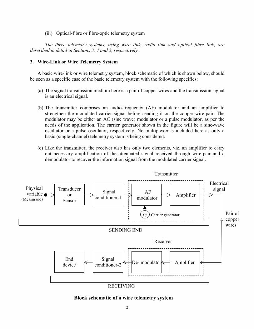
A basic wire-link or wire telemetry system, block schematic of which is shown below, should be seen as a specific case of the basic telemetry system with the following specifics:
(a) The signal transmission medium here is a pair of copper wires and the transmission signal is an electrical signal.
(b) The transmitter comprises an audio-frequency (AF) modulator and an amplifier to strengthen the modulated carrier signal before sending it on the copper wire-pair. The modulator may be either an AC (sine wave) modulator or a pulse modulator, as per the needs of the application. The carrier generator shown in the figure will be a sine-wave oscillator or a pulse oscillator, respectively. No multiplexer is included here as only a basic (single-channel) telemetry system is being considered.
(c) Like the transmitter, the receiver also has only two elements, viz. an amplifier to carry out necessary amplification of the attenuated signal received through wire-pair and a demodulator to recover the information signal from the modulated carrier signal.
Block schematic of a wire telemetry system
Transducer or
Sensor
Signal conditioner-1
≈
Physical variable
(Measurand)
Electrical signal
Pair of copper wires
SENDING END
RECEIVING END
AF modulator Amplifier
End device
Signal conditioner-2 De- modulator Amplifier
Transmitter
Receiver
G Carrier generator

3
4. Radio or Wireless Telemetry System
Block schematic of a basic radio telemetry system is shown below. This can also be treated as a specific case of the basic telemetry system with following details:
(a) The signal transmission medium here is a radio link, comprising a transmitting antenna
(TA), a receiving antenna (RA) and the space between the two used for propagation of radio wave from TA to RA.
(b) The transmitter comprises the following components: (i) RF modulator: Either AM or FM type, depending on the performance, bandwidth
and cost considerations. and an amplifier. (ii) Band pass filter (BPF): Stops any undesired frequencies produced by the RF
modulator and any noise generated internally and allows only the desired frequency band for transmission.
(iii) Power amplifier: To suitably amplify the power of the signal before feeding it to the transmitting antenna.
(c) The receiver also comprises three components as under:
(i) Input filter or tuner: To select the relevant radio signal out of the several radio signals that may be picked by the receiving antenna.
(ii) Input amplifier (iii) Demodulator: Either AM or FM type, so as to match the type of the modulator.
Physical variable
(Measurand)
Block schematic of radio telemetry system
Transducer or
Sensor
Signal conditioner-‐1
Antenna
SENDING END
RECEIVING END
RF modulator
Power amplifier
End device
Signal conditioner-‐2
De-‐ modulator
Transmitter
Receiver
~ RF
oscillator
BPF
Input filter
Antenna
Radio wave
Input amplifier

4
4.1 Short-Range Radio Telemetry System The schematic given above is in principle valid for a basic short-range telemetry system also.
The transmitter power may be very small as the range is very short, typically from a few metres or several tens of metres. The choice of radio frequency will be guided by the cost consideration and local requirements.
4.2 Satellite Radio Telemetry System
Block schematic of a basic satellite radio telemetry system is shown below. This system can
be considered as an advanced version of the basic radio telemetry system discussed earlier with the following advanced features:
(a) The communication between the transmitter and receiver takes place via a
communication satellite, which is a machine that keeps rotating around the earth and is equipped with one or more transponders acting as radio-wave repeaters in the sky.
(b) The radio frequencies (RF) used are normally higher than 3.3 GHz, known as microwave frequencies.
Transducer or sensor
Signal
conditioner-‐1
Physical variable
(Measurand)
Antenna
SENDING EARTH-‐STATION
Block schematic of a satellite radio telemetry system
IF-‐to-‐RF
upconverter
Power amplifier
Transmitter
IF
modulator
End device
Signal conditioner-‐2
RECEIVING EARTH-‐STATION
Input filter & amplifier
IF de-‐
modulator
RF-‐to-‐IF down-‐
converter
Antenna
Radio wave Radio
wave
Satellite transponder
Receiver
∼
∼
IF carrier generator
Microwave generator
Microwave generator
∼

5
(c) The transmitter in the sending earth-station incorporates, as shown in the figure, the following: (i) Intermediate-frequency (IF) modulator: It uses, typically, frequency modulation
(FM) in case of analog communication, or PSK, QPSK or QAM in case of digital communication.
(ii) IF-to-RF up-converter: It comprises a mixer followed by a band-pass filter, and its RF output is at the so-called uplink frequency.
(iii) Power amplifier.
(d) The transponder has a frequency translator (mixer plus band-pass filter) in addition to filters and a power amplifier. Its role is to receive microwave signal from one earth station, amplify, convert a higher-band uplink frequency to a lower-band down-link frequency, amplify and then retransmit to the other earth station.
(e) The receiver in the receiving earth-station receives the radio signal at downlink
frequency. It incorporates, as shown in the figure, an input filter, amplifier, RF-to-IF down-converter (that converts the downlink frequency signal to an IF signal) and an IF demodulator.
5. Optical-Fibre or Fibre-Optic Telemetry System Block schematic of a basic optical fibre telemetry system, presented in the figure below,
shows the important components of the transmitter and receiver. The highlights of the system are as follows:
(a) The transmission signal is a high-intensity narrow infrared optical beam.
(b) The signal transmission medium is an optical fibre, which works on the principle of total internal reflection and thereby serves as the waveguide for the propagation of the infrared optical beam from the transmitter to the receiver.
(c) The transmitter includes the following: (i) PCM modulator: It gets a digitized value of the measurand from signal conditioner-
1 and produces binary voltage pulses in a coded sequence. (ii) voltage-to-current converter: It converts the coded binary voltage pulses into
corresponding current pulses, as the next element, that is the light source, works on current input.
(iii) Light source: Usually an injection laser diode (ILD), it converts the binary current pulses to binary optical pulses.
(iv) Light-source to optical-fibre coupling unit (also called simply as source-to-fibre coupler).
(d) The receiver includes components performing the complementary functions of the
transmitter components in reverse order. These are:

6
(i) Optical-fibre to light detector coupling unit (also called simply as fibre-to-detector coupler).
(ii) Light detector: Usually a PIN diode is used to detect the binary optical pulses it gets from the optical fibre and to convert them to binary current pulses.
(iii) Current to voltage converter (iv) PCM demodulator: which delivers digital voltage signal to the end device through
an appropriate signal conditioner. In case the end device requires an analog input signal, the signal conditioner-2 would include a digital-to-analog converter (DAC). This is generally not the case, as digital end devices are preferred to analog end devices these days. Thus, normally DAC is not present.
6. Further Classification of Telemetry Systems
Telemetry systems were classified in Chapter-1 on the basis of the modulation method used
as under:
(i) DC telemetry systems 1. Direct voltage telemetry system 2. Direct current telemetry system
(ii) AC telemetry systems
1. Amplitude modulation (AM) telemetry system 2. Frequency modulation (FM) telemetry system
Block schematic of an optical-‐fibre telemetry system
Transducer or Sensor
Signal
conditioner-‐1
≈
Physical variable
(Measurand)
Optical Signal
Optical fibre
SENDING END
RECEIVING END
Modulator (PCM)
V-‐to-‐I
converter
End
device
Signal
conditioner-‐2
De-‐
modulator
I-‐to-‐V
converter
Transmitter
Receiver
Light source
Source-‐to-‐
fibre coupling
Light
detector
Fibre-‐to-‐ detector coupling

7
(iii) Pulse telemetry systems 1. Pulse amplitude modulation (PAM) telemetry system 2. Pulse width modulation (PWM) telemetry system 3. Pulse phase modulation (PPM) telemetry system 4. Pulse frequency modulation (PFM) telemetry system 5. Pulse code modulation (PCM) telemetry system
The same were also classified on the basis of the type of information signal as under:
(i) Analog telemetry systems
1. Direct voltage telemetry system 2. Direct current telemetry system 3. Amplitude modulation (AM) telemetry system 4. Frequency modulation (FM) telemetry system 5. Pulse amplitude modulation (PAM) telemetry system 6. Pulse width modulation (PWM) telemetry system 7. Pulse phase modulation (PPM) telemetry system 8. Pulse frequency modulation (PFM) telemetry system
(ii) Digital telemetry system
1. Pulse code modulation (PCM) telemetry system The afore-listed telemetry systems, along with their merits and limitations, will be discussed
in the following sections.
7. DC Telemetry Systems
The transmission signal for DC telemetry systems is either a DC voltage or a DC current and
the signal transmission medium is essentially a pair of copper wires. Obviously no modulation or carrier is used in these systems.
7.1 Direct Voltage Telemetry System Principle: Transmission signal for this telemetry system is a direct voltage (DC voltage) signal and the signal transmission medium is essentially a copper wire line, which is usually designed for a maximum voltage of about 80V. Sending-End Scheme: As shown in the figure below, the transducer (sensor) converts the input physical variable (measurand) to an electrical quantity, which is either an electrical parameter or an electrical signal. This output is processed by appropriate electronic circuits (signal conditioner unit) to yield a voltage signal, typically in the range of 0-1V to 0-10V. Typically, the voltage is linearly proportional to the value of the measurand. This voltage signal is then suitably amplified to a value Vdc1 and transmitted on the copper wire link.

8
Receiving-End Scheme: To maintain simplicity of the system, the end device at the receiving end is a permanent-magnet moving-coil (PMMC) voltmeter. This type of meter has two important advantages of high sensitivity and scale linearity. The meter measures the voltage at the receiving end of the line, Vdc2. Its scale is calibrated in terms of measurand (M), so that the user can read the value of M directly.
Transmission Error: The voltage at the receiving end is given by
Vdc2 = Vdc1 – I R
where I is the line current and R is the resistance of the line. The IR drop can be accounted for in the calibration of the complete telemetry system. However, R changes with the ambient temperature and thus calibration remains valid only for the temperature at which the calibration was carried out. Any variations in the temperature would, therefore, lead to a telemetry error (specifically the transmission error part). To control or minimize this error, one has to minimize I, R and the temperature variations to which the wire line is subjected.
Based on the foregoing analysis, the following measures can be recommended for minimizing transmission error in this telemetry system:
(a) The resistance of the PMMC voltmeter should be maximum for a minimum value of the line current, I.
(b) The telemetry system should be used for short distances only to ensure a low value of the line resistance, R.
(c) Only an underground cable, as against open wires, should be used because the former is not directly exposed to the usually large variations in ambient temperature.
Merits/ Advantages: The obvious merits of direct voltage telemetry system are 1. Simplicity of the system and its components 2. Low cost of the system as there are no specialized components
Demerits/ Disadvantages: The demerits of this telemetry system are
1. It can be used only for short distances as both the error and the cost of line increase with the length of the wire line.

9
2. As the line current is small, the leakage currents could become comparable and thereby cause a large error in the meter reading.
Application: Because of the above demerits, this type of telemetry system is not favoured in practice.
7.2 Direct Current Telemetry System
Principle: Transmission signal for this telemetry system is a direct current (DC current) signal and the signal transmission medium is essentially a copper wire line. The most commonly used current signal is 4-20mA, but sometimes other ranges like 0-20mA or 0-10mA are also used in industry. Sending-End Scheme: As can be seen in the figure below, this telemetry scheme is very similar the direct voltage telemetry scheme discussed earlier. The obvious difference in the sending-end schemes is that the direct current system employs a voltage to current converter while the direct voltage system uses a voltage amplifier.
Receiving-End Scheme: The end device is a PMMC milli-ammeter as it has to read the value of the line current at the receiving end, Idc2, which is in milli-ampere range. Its scale is calibrated in terms of the measurand (M), so that the user can read the value of M directly.
Transmission Error: As illustrated in the above figure, the line current at the receiving end is given by
Idc2 = Idc1 – Ileakage
where Idc1 is the line current at the sending end and Ileakage is the small current leaking from one wire of the line to the other wire or to the ground due to a finite value of insulation resistance. This reduction in the line current from Idc1 to Idc2 due to leakage can be accounted for in the calibration of the complete telemetry system. However, the leakage current changes with the

10
ambient temperature and thus calibration remains valid only for the temperature at which the calibration was carried out. Any variations in the temperature would, therefore, lead to a telemetry error (specifically the transmission error part). To control or minimize this error, one has to minimize the leakage current and the variations in the temperature to which the wire line is subjected.
Therefore, the following measures can be taken to minimize transmission error in the direct current telemetry system, which are similar to those identified for the direct voltage system:
(a) The insulation resistance between the wires of the line and that between each wire and earth should be maximum for minimizing the leakage.
(b) The telemetry system should be used for short distances only, because the value of Ileakage is the product of the leakage current per unit length of the given wire cable and its total length.
(c) Only an underground cable, as against open wires, should be used as the former is not directly exposed to the usually large variations in ambient temperature.
Merits/ Advantages: The merits of direct current telemetry system are 1. Simplicity of the system and its components 2. Low cost of the system as there are no specialized components 3. The line current is much more than the leakage current and, therefore, the latter has
insignificant effect on the accuracy of measurement. 4. The “live-zero” system, like the popular 4-20mA signal system, can readily
differentiate between a zero input (i.e. zero value of the measurand) and an open or short circuit in the line.
Demerits/ Disadvantages: The only demerit or limitation of this telemetry system is that it can be used only for short distances because (a) the error due to leakage can become substantial if the length of the wire line is large, and (b) the cost of the line increases directly with its length. Application: Because of the above merits and limitation, this type of telemetry system is very popular for in-plant telemetry where the distances are generally short.
8. AC Telemetry Systems The transmission signal for AC telemetry systems is a modulated AC (sinusoidal) signal. The
type of modulation is either amplitude modulation (AM) or frequency modulation (FM). The signal transmission medium is either a pair of copper wires, which would use an audio-frequency (AF) carrier, or a radio link, which would need a radio-frequency (RF) carrier.

11
8.1 AM Telemetry System Principle: Transmission signal for this telemetry system is an amplitude-modulated AC signal. Generally an AF sinusoidal signal is used as the carrier and a wire line as the transmission medium. Sending-End Scheme: This system is preferably used with variable-inductance transducers, either single or complimentary-paired ones. These transducers need to be connected in an AC-excited Wheatstone bridge. The best frequency of excitation is typically a few kHz, which falls in AF range. A simple AM telemetry system based on these considerations is shown in the figure below. A complementary pair of inductive transducers, T1 & T2, forms two adjoining arms of the bridge, while the remaining arms are two fixed identical resistances, R1 & R2. The output of the bridge, which is the out-of-balance voltage, has obviously the same frequency as that of the excitation source (oscillator), while its amplitude increases with the variation of the transducer inductance, or in other words with the value of the measurand applied to it. Thus the bridge output is an amplitude-modulated AF signal, where the value of the measurand is causing the modulation. This signal is amplified in an AC amplifier to the desired level of amplitude before sending it on the wire line.
Receiving-End Scheme: For the reasons given under Direct Voltage Telemetry System, the end device is a PMMC voltmeter. Since it can read only a DC or a unidirectional voltage, a rectifier is placed before the meter. Because of the mechanical inertia of its moving parts, the meter responds to the average or peak value of the rectified voltage waveform. Its scale is calibrated in terms of the measurand (M), so that the user can read the value of M directly.

12
Transmission Error: If we compare the performance of the AM telemetry system with that of the direct voltage telemetry system, the voltage drop in the present case will be more because the line inductance in addition to line resistance will cause this drop. Consequently the variation in voltage drop and the error will also be higher.
The measures to be taken to minimize transmission error in the AM telemetry system are identical to those identified for the direct voltage system. These are as follows:
(a) The resistance of the PMMC voltmeter should be maximum for a minimum value of the line current.
(b) The telemetry system should be used for short distances only to ensure a low value of the line impedance.
(c) Only an underground cable, as against open wires, should be used because the former is not directly exposed to the usually large variations in ambient temperature.
Merits/ Advantages: The obvious merits of AM telemetry system are 1. Simplicity of the system and its components 2. Low cost of the system as there are no specialized components
Demerits/ Disadvantages: The demerits of AM telemetry system are
1. It can be used only for short distances as both the error and the cost of line increase with the length of the wire line.
2. As the line current is small, the leakage currents could become comparable and thereby cause a large error in the meter reading.
Application: Because of the above demerits, AM telemetry systems are not in common use. It may be useful only where inductive transducer suits the given measurand and the distance is short.
8.2 FM Telemetry System Principle: Transmission signal for this telemetry system is a frequency-modulated AC signal. Generally a RF sinusoidal signal is used as the carrier and a radio link as the transmission medium. Sending-End Scheme: FM telemetry has been largely used for short range radio telemetry and a simple telemetry system of this type is shown in the figure below. It can be best understood with reference to the basic telemetry system given in the first Section. A transducer converts the given physical variable (measurand) into an electrical output, which is conditioned/ processed by an appropriate signal conditioner to yield a dc voltage proportional to the value of the measurand, M. This voltage signal is used for the frequency modulation (FM) of a radio-frequency (RF) carrier. The frequency-modulated radio-frequency (FM-RF) signal is applied to a transmitting

13
antenna through a band-pass filter (BPF) so as to pass only the desired frequency band. Power amplification after modulation is generally not required as a small transmitter power is sufficient for sort-range radio transmission.
Receiving-End Scheme: The receiver selects the desired signal by employing a band-pass filter. This signal, being a FM-RF signal, is demodulated using a frequency demodulator thereby recovering the information signal. Signal conditioner-2 conditions/ processes the information signal to make it compatible to the given end device. The end device thus gets the intended information, that is, the value of the measurand.
Transmission Error: Since the information (value of M) resides in the frequency, and not the amplitude of the transmission signal, no telemetry error results from the attenuation or variations in the attenuation of this signal during its propagation. However, some error can occur due to selective fading of the radio signal during bad weathers if the telemetry system is used outdoor and due to high-frequency noise. Standard solutions to both the problems are available with radio communication engineers and, therefore, not dealt with here.
Merits/ Advantages: The merits of FM telemetry system are as under:
1. The most important advantage is that it can be used conveniently wherever it is difficult or impossible to access the sensor output with wire leads.
2. The system and its components are quite simple.

14
3. The system is inexpensive as only ordinary/ standard components are used. 4. As the information (value of M) resides in the frequency, and not the amplitude of the
transmission signal, no telemetry error results from the attenuation or variations in the attenuation of this signal during its propagation.
5. It can be easily extended to a multi-channel telemetry system using frequency division multiplexing (FDM), in which case each channel uses a carrier of different radio frequency.
Demerits/ Disadvantages
1. In outdoor telemetry applications, its performance can be problematic in bad weathers 2. It can become expensive when used with long range-range transmissions in
commercial radio frequency band.
Application: Because of the above merits, almost all short-range radio telemetry systems are FM telemetry systems.
9. Analog Pulse Telemetry Systems
PFM, PAM, PWM and PPM type pulse telemetry systems are all analog telemetry systems,
while the fifth type, i.e. PCM telemetry system, is the only digital telemetry system. Of the four analog systems, only the PWM telemetry system of multi-channel type has some significance for industrial application and will, therefore, be discussed here. Although PAM telemetry is rarely used by itself, it forms the basis of the PWM telemetry. For this reason, we shall first discuss the principles and schematics of multi-channel PAM and single-channel PWM telemetry systems and then take up a multi-channel PWM telemetry system. The PCM or digital telemetry system will be dealt with in the next Section.
9.1 Multi-Channel TDM-PAM Telemetry System Principle: Transmission signal for PAM telemetry takes the form of amplitude-modulated pulses and multi-channel operation is achieved through time-division multiplexing (TDM). Sending-End Scheme: A 4-channel PAM telemetry system is shown in the figure below. It can be seen that the four physical variables or measurands, M1 to M4, are applied to appropriate transducers, T1 to T4, respectively. The transducer outputs are processed in suitable signal conditioners, SC-1 to SC-4, respectively, such that their outputs are the dc voltages, V1 to V4, proportional to M1 to M4, respectively. These voltage signals are applied to a 4-channel multiplexing switch (which is an integrated circuit device) at its input terminals, IN1 to IN4. The multiplexing switch functions under the control of a clock and makes one of the inputs available at a time at the output terminal, OUT, for a short duration equal to the time period of the clock. The switch normally functions in a cyclic order. The output of the switch is thus pulses with their amplitudes modulated by the input

15
signals in cyclic order. The output is thus a time-multiplexed PAM signal, shown in the figure as a sequence of amplitude-modulated pulses, P1 to P4.
It is expected that the first telemetry channel should always connect the first measurand at the sending end to the first PMMC voltmeter at the receiving end. Similar thing should be true for other channels too. To that end, the de-multiplexing switch in the receiving station should run in synchronism (both in terms of frequency or rate and phase or position). This is achieved by generating a synchronization pulse (sync pulse) before the start of each cycle of the multiplexing switch and adding this pulse to PAM signals before transmitting them to the receiving end, as shown in the block schematic. The sync pulse has the same width or duration as do the PAM pulses, but its amplitude is much larger than the maximum amplitude of any PAM pulse.
Receiving-End Scheme: The receiver gets the sync pulse as well as PAM signals. The sync pulse is identified by a sync pulse detector (on the basis of amplitude) and delivered to the synchronization circuit, which acts on the de-multiplexing switch to synchronize it in frequency and phase with the multiplexing switch. The time-multiplexed PAM signal (sequence of amplitude-modulated pulses, P1 to P4) is applied to the de--multiplexing switch, which outputs the pulses P1 to P4 at its output terminals, OUT1 to OUT4, respectively. These pulsed signals are interpolated by the signal interpolators, SI-1 to SI-4 thereby producing continuous voltage signals, V1 to V4, proportional to P1 to P4, respectively. Finally, these voltages are read on

16
respective PMMC voltmeters, which are calibrated in terms of values of the measurands, M1 to M4.
Merits/ Advantages: The advantage of PAM telemetry system over the PWM and PCM telemetry systems is that it is relatively simpler and cheaper. Demerits/ Disadvantages: The disadvantage can be understood from the simple fact that attenuation and changes in attenuation of the signal can result in much larger errors with PAM signals (because information is contained in the amplitude of the pulses) than with PWM and PCM signals (as no information is contained in the amplitude of the pulses). Application: Because of the above disadvantage, PAM telemetry systems are rarely used.
9.2 Single-Channel PWM Telemetry System Principle: Transmission signal for PWM telemetry (also known as PDM telemetry) takes the form of width-modulated (or duration-modulated) pulses. Sending-End Scheme: A single-channel PWM telemetry system is shown in the figure below. It can be seen that the physical variable or measurand M is applied to an appropriate transducer, the output of which is processed suitably by the signal conditioner to produce a dc voltage, Vdc, proportional to M. This voltage is applied to a pulse-width modulator to produce PWM signal, which is transmitted to the receiving end after necessary amplification and/or conversion of the signal by the transmitter. The nature of signal conversion will depend on the signal transmission medium as explained earlier.

17
Receiving-End Scheme: The receiver recovers the PWM signal from the received signal, which is applied to a pulse shaper to make the amplitude of these pulses constant (independent of the attenuation suffered during transmission) and their edges sharp. These perfectly-shaped width-modulated pulses are then input to a low-pass filter as shown in the block schematic. The filter produces a d.c. voltage, Vdc, proportional to the pulse width of the input pulses, and thus proportional to M. This d.c. voltage is read on a PMMC voltmeter serving as the end device at the receiving end. The voltmeter is calibrated in term of the value of the measurand M, so that the user can read the value of M directly on this voltmeter. Merits/ Advantages:
1. The main advantage of PWM telemetry system as compared to direct voltage and PAM telemetry systems is that as the information (value of M) resides in the width and not in the amplitude of the pulses, theoretically no telemetry error can result from the attenuation or the variations in attenuation of the signal during transmission.
2. As compared to the PCM telemetry system, the PWM telemetry system is cheaper because it does not need the expensive components like ADC and sample-and-hold circuit.
Application
1. PWM telemetry suits more to wire-line links than to radio or optical-fibre links. 2. Single-channel PWM telemetry systems are not popular because of their complexity and
high cost.
9.3 Multi-Channel TDM-PWM Telemetry System
Principle: Transmission signal for PWM telemetry (also known as PDM telemetry) takes the form of width-modulated (or duration-modulated) pulses. Multi-channel operation is achieved through time-division multiplexing (TDM). Sending-End Scheme: A 4-channel PWM telemetry system is shown in the figure below. The sending end scheme of this system is quite similar to that of the multi-channel PAM telemetry system discussed above with following differences: (a) A pulse-amplitude to pulse-width converter is added after the multiplexing switch. This converts the PAM signals to PWM signals. (b) The sync pulse has the same amplitude as do the PWM pulses, but its width is much more than the maximum width of any PWM pulse. (c) Since the PWM and sync pulses are binary in amplitude (low or high value), an OR-gate is used here in place of the adder of PAM scheme.

18
Receiving-End Scheme: The receiving end scheme is also similar to that of the PAM system. One important difference is that the sync pulse detector here works on the basis of pulse width (rather than pulse amplitude) and the second major difference is that the PWM scheme uses low-pass filters in place of the signal interpolators of PAM system. The output of a low-pass filter with pulse-width modulated pulses of constant amplitude as the input is a continuous voltage of a magnitude proportional to the pulse width.
Merits/ Advantages:
1. The main advantage of PWM telemetry system as compared to PAM telemetry system is that as the information (value of M) resides in the width and not in the amplitude of the pulses, theoretically no telemetry error can result from the attenuation or the variations in attenuation of the signal during transmission.
2. As compared to the PCM telemetry system, the PWM telemetry system is cheaper because it does not need the expensive components like ADC and sample-and-hold circuit.

19
Application: Because of the above advantage, majority of multi-channel wire-line analog telemetry systems are of PWM type.
10. PCM/Digital Telemetry System 10.1 Single-Channel PCM/Digital Telemetry System Principle: The transmission signal in PCM telemetry system takes the form of a coded sequence of binary pulses. Thus the information represented by the transmitted pulses is digital. None of the attributes of these pulses, like amplitude, width or phase, is analogous to the information. Sending-End Scheme: Block schematic of a single-channel PCM telemetry system is shown in the figure below. The physical variable or measurand M is applied to an appropriate transducer, the output of which is processed suitably by the signal conditioner to produce a dc voltage, Vdc, proportional (analogous) to M. This analog voltage is sampled at regular intervals (or sampling frequency) and converted to its equivalent digital value by an analog to digital converter (ADC). Generally a successive-approximation type ADC is used in this type of application and its resolution ranges from 8 to 16 bits. As the analog voltage follows the time-variations in the value of the measurand, its value changes continuously. Any change in the analog input to the ADC of successive-approximation type, while A-to-D conversion is going on, can cause serious error in the output of the ADC. The problem is avoided by using a sample-and-hold circuit (S/H circuit), rather than a simple sampling circuit, before the ADC as shown in the block schematic. The ADC is followed by the circuits described below in that order: Parity/CRC Bits Adder: The data transmission can be either asynchronous or synchronous. In case of asynchronous transmission, this circuit adds a parity bit to each character, that is, n-bit data output of the ADC. In case of synchronous transmission, the circuit adds a certain number of cyclic-redundancy-check bits (CRC bits) at the end of the data bits. PCM Modulator: It encodes the augmented data (comprising data bits and parity/CRC bits) into a series of coded pulses using a certain PCM code Transmitter: The transmitter has two functions to perform:
(a) Addition of Synchronization Information: In case of asynchronous transmission, it adds start and stop pulses before and after each data character. In case of synchronous transmission, it adds a synchronization (sync) bit pattern in front of the entire data block.
(b) Signal Conversion: The transmitter converts the coded voltage pulses (PCM signal) into a
transmission signal to suit the given transmission medium and the desired range of transmission. For details, see Section 3 on Wire-Link Telemetry System, Section 4 on Radio or Wireless Telemetry System, Section 4.1 on Short-Range Radio Telemetry System, Section 4.2 on Satellite Radio Telemetry System and Section 5 on Optical Fibre Telemetry System, which address various practical situations.

20
Since the S/H circuit, ADC and all other circuits mentioned above operate in tandem, their operations need to be synchronized using a common reference clock, as shown in the diagram. Receiving-End Scheme: The receiver has two functions to perform here: (a) It synchronizes its own operation with the transmitter by using the start and stop pulses (for
asynchronous transmission) or the sync bit pattern (for synchronous transmission). (b) It carries out reverse signal conversion, that is, it converts the transmission signal received
by it into coded voltage pulses (PCM signal). Thereafter, a PCM demodulator decodes the coded voltage pulses back into ‘augmented data’ and converts them into parallel bits. This data is passed on to an error detector, which verifies the correctness of the data from the parity or CRC bits. In case an error is detected, the information is passed on to the error control system for suitable action. If no error is found, then the data bits alone are passed on to the end devices. All the circuits, including the end devices, operating in tandem, are synchronized by a clock in the receiving end of the telemetry system, as shown in the diagram. This clock has the same frequency as the one in the sending end.

21
Merits/ Advantages: As compared to analog telemetry systems in general, the digital or PCM telemetry system has the following advantages:
1. Like all digital systems in general, the digital telemetry system has high immunity to noise.
2. Like digital communication systems, the digital telemetry uses error control techniques as a standard feature thereby ensuring that the data reaching the end devices is error free.
Demerits/ Disadvantages: The only disadvantage of digital telemetry, when compared with analog telemetry systems, for very simple or ordinary applications not demanding high accuracies, may be its higher cost. Application: Because of the above advantages, PCM telemetry systems are now generally preferred over analog telemetry systems.
10.2 Multi-Channel PCM/Digital Telemetry System
Principle: The transmission signal in PCM telemetry system takes the form of a coded sequence of binary pulses. Thus the information represented by the transmitted pulses is digital. None of the attributes of these pulses, like amplitude, width or phase, is analogous to the information. The multi-channel operation is achieved through time-division multiplexing (TDM) as in the cases of PAM and PWM telemetry systems discussed earlier. Sending-End Scheme: A 4-channel PCM telemetry system is shown in the figure below. The initial part of the sending end scheme of this system is quite similar to that of the PAM telemetry system upto the point of obtaining PAM signal. The subsequent components have their roles as under: Sample-and Hold (S/H) Circuit: The amplitude of PAM signal, for example P1, follows the variations in the magnitude of the continuous (analog) signal V1. Similar is the case with the other PAM signals, P2, P3 and P4. This can cause serious error in the output of an ADC of successive-approximation type, which is commonly used in applications like PCM telemetry. To overcome the problem, a sample-and-hold circuit is placed before the ADC to sample the signal and hold the sample at a constant value. Analog-to-Digital Converter (ADC): The sampled value of the analog signal is converted to its equivalent digital value by an ADC, which is generally of successive-approximation type. The width or resolution of the ADC usually ranges from 8 to 16 bits. Parity/CRC Bits Adder: The data transmission can be either asynchronous or synchronous. In case of asynchronous transmission, this circuit adds a parity bit to each character, that is, n-bit data output of the ADC. In case of synchronous transmission, the circuit adds a certain number of cyclic-redundancy-check bits (CRC bits) at the end of the complete data block.

22
PCM Modulator: It encodes the augmented data (comprising data bits and parity/CRC bits) into a series of coded pulses using a certain PCM code. Transmitter: The transmitter has two functions to perform: a) Addition of Synchronization Information: In case of asynchronous transmission, it adds start
and stop pulses before and after each data character. In case of synchronous transmission, it adds a synchronization (sync) bit pattern in front of the entire data block.
b) Signal Conversion: The transmitter converts the coded voltage pulses (PCM signal) into a
transmission signal to suit the given transmission medium and the desired range of transmission. For details, see Section 3 on Wire-Link Telemetry System, Section 4 on Radio or Wireless Telemetry System, Section 4.1 on Short-Range Radio Telemetry System, Section 4.2 on Satellite Radio Telemetry System and Section 5 on Optical Fibre Telemetry System, which address all the practical situations.
Since the S/H circuit, ADC and all other circuits mentioned above operate in tandem, their operations need to be synchronized using a common reference clock, as shown in the diagram.

23
Receiving-End Scheme: The receiver has two functions to perform here: (a) It synchronizes its own operation with the transmitter by using the start and stop pulses (for
asynchronous transmission) or the sync bit pattern (for synchronous transmission). (b) It carries out reverse signal conversion, that is, it converts the transmission signal received
by it into coded voltage pulses (PCM signal). Thereafter, a PCM demodulator decodes the coded voltage pulses back into ‘augmented data’ and converts them into parallel bits. This data is passed on to an error detector, which verifies the correctness of the data from the parity or CRC bits. In case an error is detected, the information is passed on to the error control system for suitable action. If no error is found, then the data bits alone are passed on to the end devices. All the circuits, including the end devices, operating in tandem, are synchronized by a clock in the receiving end of the telemetry system, as shown in the diagram. This clock has the same frequency as the one in the sending end. In the block schematic given here, three commonly used end devices are shown: (a) A multiplexed digital display unit for displaying the values of the measurands one by one. (b) A digital storage unit for storing values of all the measurands for a later analysis. (c) A data processor for analyzing the data immediately. The receiver sends channel information along with data (for identifying the channel number for each data) to these end devices so that the data reaches the correct end device. Merits/ Advantages: As compared to analog telemetry systems in general, the digital or PCM telemetry system has the following advantages: 1. Like all digital systems in general, the digital telemetry system has high immunity to noise. 2. Like digital communication systems, the digital telemetry uses error control techniques as a
standard feature thereby ensuring that the data reaching the end devices is error free. Demerits/ Disadvantages: The only disadvantage of digital telemetry in very simple or ordinary applications can be its higher cost when compared with analog telemetry.
Application: Because of the above advantages, PCM telemetry systems are used in all applications demanding high performance and/or involving large number of channels.
xxxxxxxxxxxxxxxxxxxxxx