2017 Award Nomination - NACE...
15
1 2017 Award Nomination Title of Innovation: Distributed Smart TR’s for Impressed Current Cathodic Protection Nominee(s) David Celine, Omniflex Tadek Dzwig, Omniflex Martin Elsner, Omniflex Agustin Ritacco, Omniflex Category: Cathodic Protection Coatings and Linings Instrumentation Cathodic Protection Testing Materials Design Integrity Assessment Chemical Treatment Other—fill in Dates of Innovation Development: from January 2014 to July 2016 Web site: www.omniflex.com/cp Summary Description: Impressed Current Cathodic Protection systems are in wide spread use for their effectiveness in protecting steel piling and concrete columns and beams. But in long structures, such as wharves and bridges, limited space and access has mandated that traditional ICCP systems most often be mounted at each end of the structure. This requires a significant cost in copper cabling and associated installation hardware such as cable trays, that can impact on project cost and sometimes even feasibility. A new technology developed by Omniflex is allowing such systems to be installed with significant reductions in installation cost while at the same time drastically increasing the
Transcript of 2017 Award Nomination - NACE...

1
2017 Award Nomination Title of Innovation: Distributed Smart TR’s for Impressed Current Cathodic Protection Nominee(s) David Celine, Omniflex Tadek Dzwig, Omniflex Martin Elsner, Omniflex Agustin Ritacco, Omniflex Category: Cathodic Protection
Coatings and Linings Instrumentation Cathodic Protection Testing Materials Design Integrity Assessment Chemical Treatment Other—fill in
Dates of Innovation Development: from January 2014 to July 2016 Web site: www.omniflex.com/cp
Summary Description: Impressed Current Cathodic Protection systems are in wide spread use for their effectiveness in protecting steel piling and concrete columns and beams. But in long structures, such as wharves and bridges, limited space and access has mandated that traditional ICCP systems most often be mounted at each end of the structure. This requires a significant cost in copper cabling and associated installation hardware such as cable trays, that can impact on project cost and sometimes even feasibility.
A new technology developed by Omniflex is allowing such systems to be installed with significant reductions in installation cost while at the same time drastically increasing the

2
number of controllable zones of protection and level of control of each zone.
By designing ‘smart’ TR modules with real-time communications built to the core, it has been possible to implement some very large CP systems with unprecedented levels of remote monitoring and control. By placing new smart TR’s with multiple independent controllable outputs close to the elements being protected, copper cable has been reduced to a minimum, the number of independently controllable zones of protection increased and real-time monitoring and control enhanced.
The communication infrastructure extends from each Transformer/Rectifier zone and reference half-cell right up to the web services that monitor these systems in real time. This in turn allows full remote monitoring and control of each zone and fully automated CP testing to be implemented in accordance with the international standards, further reducing life cycle costs and increasing assurance of levels of protection. This technology has brought the new “Internet of Things” to the world of Corrosion Protection.
3
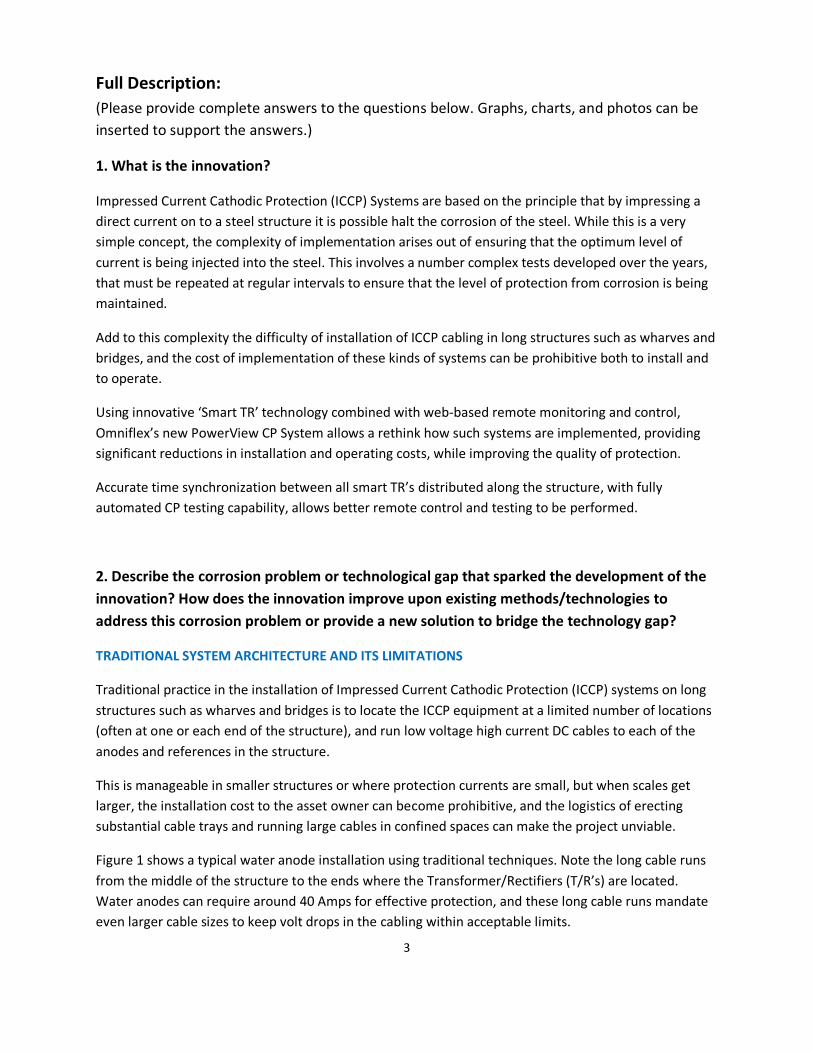
Full Description: (Please provide complete answers to the questions below. Graphs, charts, and photos can be inserted to support the answers.)
1. What is the innovation?
Impressed Current Cathodic Protection (ICCP) Systems are based on the principle that by impressing a direct current on to a steel structure it is possible halt the corrosion of the steel. While this is a very simple concept, the complexity of implementation arises out of ensuring that the optimum level of current is being injected into the steel. This involves a number complex tests developed over the years, that must be repeated at regular intervals to ensure that the level of protection from corrosion is being maintained.
Add to this complexity the difficulty of installation of ICCP cabling in long structures such as wharves and bridges, and the cost of implementation of these kinds of systems can be prohibitive both to install and to operate.
Using innovative ‘Smart TR’ technology combined with web-based remote monitoring and control, Omniflex’s new PowerView CP System allows a rethink how such systems are implemented, providing significant reductions in installation and operating costs, while improving the quality of protection.
Accurate time synchronization between all smart TR’s distributed along the structure, with fully automated CP testing capability, allows better remote control and testing to be performed.
2. Describe the corrosion problem or technological gap that sparked the development of the innovation? How does the innovation improve upon existing methods/technologies to address this corrosion problem or provide a new solution to bridge the technology gap?
TRADITIONAL SYSTEM ARCHITECTURE AND ITS LIMITATIONS
Traditional practice in the installation of Impressed Current Cathodic Protection (ICCP) systems on long structures such as wharves and bridges is to locate the ICCP equipment at a limited number of locations (often at one or each end of the structure), and run low voltage high current DC cables to each of the anodes and references in the structure.
This is manageable in smaller structures or where protection currents are small, but when scales get larger, the installation cost to the asset owner can become prohibitive, and the logistics of erecting substantial cable trays and running large cables in confined spaces can make the project unviable.
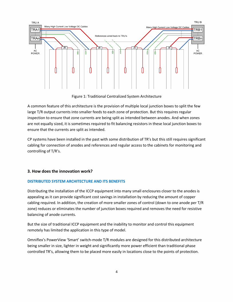
Figure 1 shows a typical water anode installation using traditional techniques. Note the long cable runs from the middle of the structure to the ends where the Transformer/Rectifiers (T/R’s) are located. Water anodes can require around 40 Amps for effective protection, and these long cable runs mandate even larger cable sizes to keep volt drops in the cabling within acceptable limits.
4
Figure 1: Traditional Centralized System Architecture
A common feature of this architecture is the provision of multiple local junction boxes to split the few large T/R output currents into smaller feeds to each zone of protection. But this requires regular inspection to ensure that zone currents are being split as intended between anodes. And when zones are not equally sized, it is sometimes required to fit balancing resistors in these local junction boxes to ensure that the currents are split as intended.
CP systems have been installed in the past with some distribution of TR’s but this still requires significant cabling for connection of anodes and references and regular access to the cabinets for monitoring and controlling of T/R’s.
3. How does the innovation work?
DISTRIBUTED SYSTEM ARCHITECTURE AND ITS BENEFITS
Distributing the installation of the ICCP equipment into many small enclosures closer to the anodes is appealing as it can provide significant cost savings in installation by reducing the amount of copper cabling required. In addition, the creation of more smaller zones of control (down to one anode per T/R zone) reduces or eliminates the number of junction boxes required and removes the need for resistive balancing of anode currents.
But the size of traditional ICCP equipment and the inability to monitor and control this equipment remotely has limited the application in this type of model.
Omniflex’s PowerView ‘Smart’ switch-mode T/R modules are designed for this distributed architecture being smaller in size, lighter in weight and significantly more power efficient than traditional phase controlled TR’s, allowing them to be placed more easily in locations close to the points of protection.

5
By introducing intelligence into each TR module, it is now possible to communicate with each of these locally placed TR modules over a single twisted pair cable or by radio communications, dramatically reducing the amount of cabling required in such installations, while increasing the amount of monitoring and control that can be achieved.
Figure 2: Distributed System Architecture
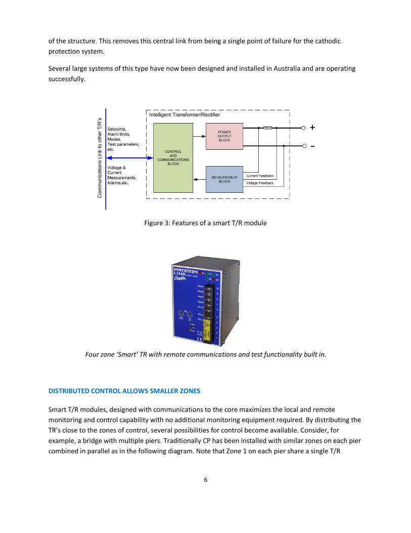
SMART TR MODULES WITH REAL TIME COMMUNICATIONS
A key component of these distributed systems that allow this architecture to be robust in practice is the ‘smart’ T/R module.
By redesigning the T/R module with the ability to communicate intelligently with the central control unit, each T/R module can perform most of the functions of the system independently, and only use the communications link to receive instructions to change settings, or to perform tests, or receive requests for information from the central control unit.
Each smart T/R module is equipped with an accurate clock, kept synchronized with the real time by the central control unit. This allows all smart T/R modules to perform testing in complete synchronization, even over large distances.
The communications link is typically a simple twisted pair cable that can operate up to 4000 feet (1200m). in length, but radio communications is also possible in more difficult applications.
Each PowerView CP smart TR module combines a power output stage to drive the anodes, independent measurement circuits to measure the output voltage, current and circuit resistance, and a communications processor to control the output, measure the inputs, and communicate with the Central Control Unit.
A key advantage of these units is their ability act independently under normal operating conditions. This means that the central control unit and communications link is not required for the ongoing protection
6
of the structure. This removes this central link from being a single point of failure for the cathodic protection system.
Several large systems of this type have now been designed and installed in Australia and are operating successfully.
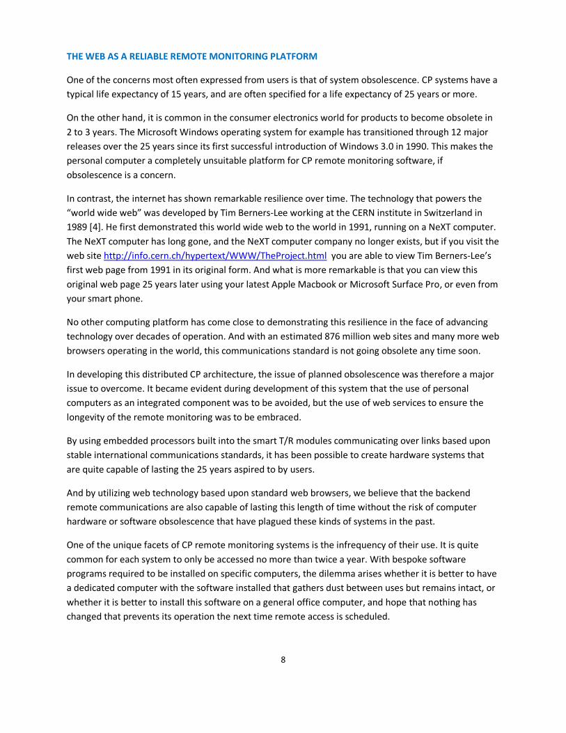
Figure 3: Features of a smart T/R module
Four zone ‘Smart’ TR with remote communications and test functionality built in.
DISTRIBUTED CONTROL ALLOWS SMALLER ZONES
Smart T/R modules, designed with communications to the core maximizes the local and remote monitoring and control capability with no additional monitoring equipment required. By distributing the TR’s close to the zones of control, several possibilities for control become available. Consider, for example, a bridge with multiple piers. Traditionally CP has been installed with similar zones on each pier combined in parallel as in the following diagram. Note that Zone 1 on each pier share a single T/R

7
output, and so balancing of the currents between the piers is dependent upon the piers behaving electrically the same.
Figure 4: Traditional sharing of zones between piers/beams
By splitting the zones vertically, rather than horizontally, and using Omniflex’s PowerView compact T/R modules with multiple output zones of control located closer to each pier, the installation cost is significantly reduced and the level of monitoring and control of each zone is significantly increased.
And by separating the central control unit with user interface from the point of protection through the communications link, a host of new possibilities arise for improving remote system access with minimum cost of cabling.
Figure 5: Distributed zones using smart T/R’s reduces cables and increases control
8
THE WEB AS A RELIABLE REMOTE MONITORING PLATFORM
One of the concerns most often expressed from users is that of system obsolescence. CP systems have a typical life expectancy of 15 years, and are often specified for a life expectancy of 25 years or more.
On the other hand, it is common in the consumer electronics world for products to become obsolete in 2 to 3 years. The Microsoft Windows operating system for example has transitioned through 12 major releases over the 25 years since its first successful introduction of Windows 3.0 in 1990. This makes the personal computer a completely unsuitable platform for CP remote monitoring software, if obsolescence is a concern.
In contrast, the internet has shown remarkable resilience over time. The technology that powers the “world wide web” was developed by Tim Berners-Lee working at the CERN institute in Switzerland in 1989 [4]. He first demonstrated this world wide web to the world in 1991, running on a NeXT computer. The NeXT computer has long gone, and the NeXT computer company no longer exists, but if you visit the web site http://info.cern.ch/hypertext/WWW/TheProject.html you are able to view Tim Berners-Lee’s first web page from 1991 in its original form. And what is more remarkable is that you can view this original web page 25 years later using your latest Apple Macbook or Microsoft Surface Pro, or even from your smart phone.
No other computing platform has come close to demonstrating this resilience in the face of advancing technology over decades of operation. And with an estimated 876 million web sites and many more web browsers operating in the world, this communications standard is not going obsolete any time soon.
In developing this distributed CP architecture, the issue of planned obsolescence was therefore a major issue to overcome. It became evident during development of this system that the use of personal computers as an integrated component was to be avoided, but the use of web services to ensure the longevity of the remote monitoring was to be embraced.
By using embedded processors built into the smart T/R modules communicating over links based upon stable international communications standards, it has been possible to create hardware systems that are quite capable of lasting the 25 years aspired to by users.
And by utilizing web technology based upon standard web browsers, we believe that the backend remote communications are also capable of lasting this length of time without the risk of computer hardware or software obsolescence that have plagued these kinds of systems in the past.
One of the unique facets of CP remote monitoring systems is the infrequency of their use. It is quite common for each system to only be accessed no more than twice a year. With bespoke software programs required to be installed on specific computers, the dilemma arises whether it is better to have a dedicated computer with the software installed that gathers dust between uses but remains intact, or whether it is better to install this software on a general office computer, and hope that nothing has changed that prevents its operation the next time remote access is scheduled.
9
And without this computer software running continuously, it is not possible to report discrepancies by exception in real-time, and the problem of secure long term storage of historical data is also a concern.
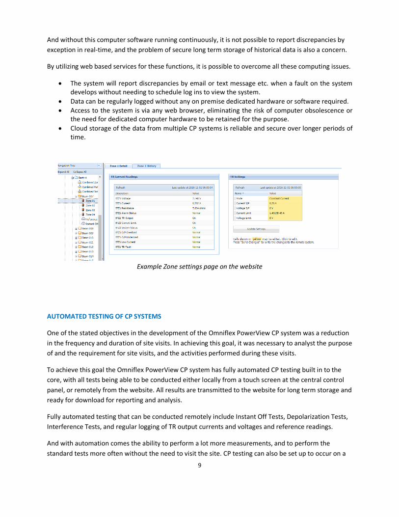
By utilizing web based services for these functions, it is possible to overcome all these computing issues.
• The system will report discrepancies by email or text message etc. when a fault on the system develops without needing to schedule log ins to view the system.
• Data can be regularly logged without any on premise dedicated hardware or software required. • Access to the system is via any web browser, eliminating the risk of computer obsolescence or
the need for dedicated computer hardware to be retained for the purpose. • Cloud storage of the data from multiple CP systems is reliable and secure over longer periods of
time.
Example Zone settings page on the website
AUTOMATED TESTING OF CP SYSTEMS
One of the stated objectives in the development of the Omniflex PowerView CP system was a reduction in the frequency and duration of site visits. In achieving this goal, it was necessary to analyst the purpose of and the requirement for site visits, and the activities performed during these visits.
To achieve this goal the Omniflex PowerView CP system has fully automated CP testing built in to the core, with all tests being able to be conducted either locally from a touch screen at the central control panel, or remotely from the website. All results are transmitted to the website for long term storage and ready for download for reporting and analysis.
Fully automated testing that can be conducted remotely include Instant Off Tests, Depolarization Tests, Interference Tests, and regular logging of TR output currents and voltages and reference readings.
And with automation comes the ability to perform a lot more measurements, and to perform the standard tests more often without the need to visit the site. CP testing can also be set up to occur on a

10
regular schedule. This increases the level of surveillance and therefore assurance of ongoing protection from corrosion, without increasing the onus on the monitoring function and therefore the cost of monitoring.
Example Automatic Instant Settings on the website
[Note: This system description is adapted from a technical paper being presented at the Australasian Corrosion Association Conference 2016 being held in Auckland, New Zealand]
4. Has the innovation been tested in the laboratory or in the field? If so, please describe any tests or field demonstrations and the results that support the capability and feasibility of the innovation.
A number of Omniflex PowerView CP systems with distributed architecture and smart T/R’s have now been delivered.
SYDNEY OPERA HOUSE WESTERN BOARDWALK
The first Omniflex PowerView distributed CP system was installed at the Sydney Opera House in 2014.
Features of this system:
Date of Installation 2014 Structure Protected Concrete piles and
beams Length of the structure being protected 480 feet (150m) Number of distributed CP cabinets 5 Number of zones of protection 85 Number of references being monitored with automated testing
135

11
View down the length of the structure
One of the five local TR Cabinets
Internals of one cabinet containing 18 independent zones and 30 reference inputs
12
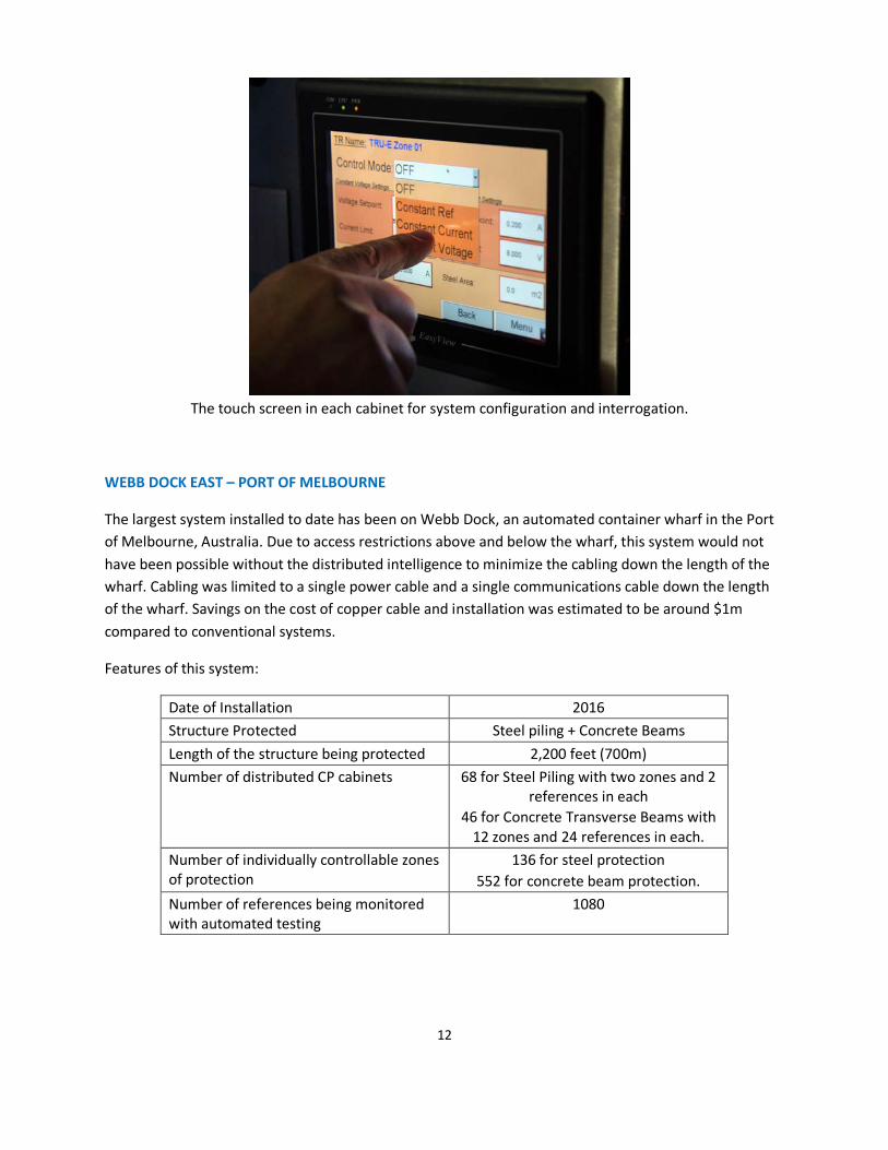
The touch screen in each cabinet for system configuration and interrogation.
WEBB DOCK EAST – PORT OF MELBOURNE
The largest system installed to date has been on Webb Dock, an automated container wharf in the Port of Melbourne, Australia. Due to access restrictions above and below the wharf, this system would not have been possible without the distributed intelligence to minimize the cabling down the length of the wharf. Cabling was limited to a single power cable and a single communications cable down the length of the wharf. Savings on the cost of copper cable and installation was estimated to be around $1m compared to conventional systems.
Features of this system:
Date of Installation 2016 Structure Protected Steel piling + Concrete Beams Length of the structure being protected 2,200 feet (700m) Number of distributed CP cabinets 68 for Steel Piling with two zones and 2
references in each 46 for Concrete Transverse Beams with
12 zones and 24 references in each. Number of individually controllable zones of protection
136 for steel protection 552 for concrete beam protection.
Number of references being monitored with automated testing
1080
13
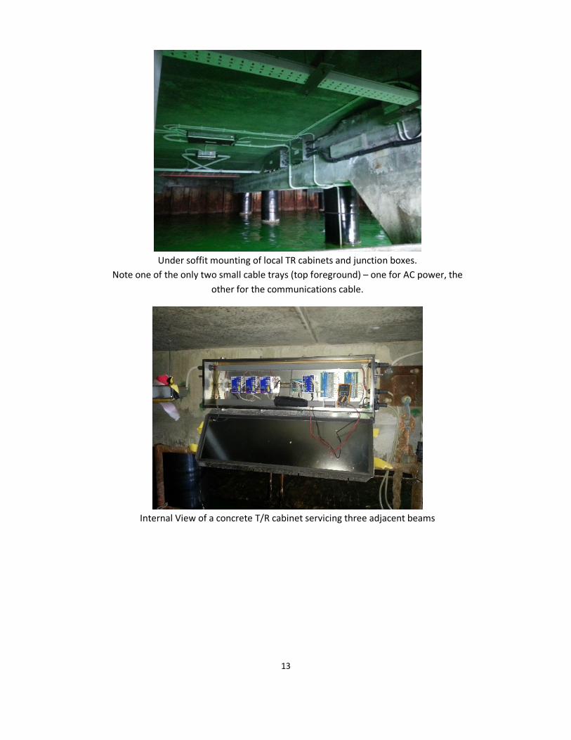
Under soffit mounting of local TR cabinets and junction boxes.
Note one of the only two small cable trays (top foreground) – one for AC power, the other for the communications cable.
Internal View of a concrete T/R cabinet servicing three adjacent beams
14
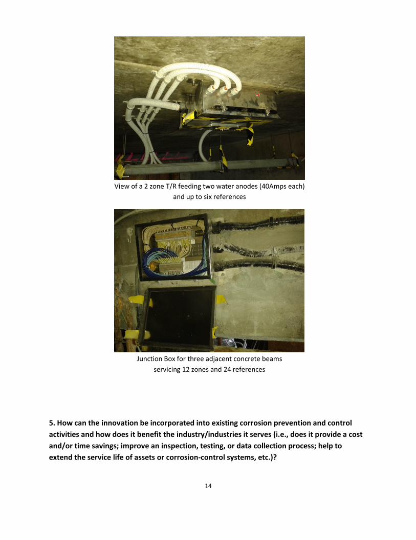
View of a 2 zone T/R feeding two water anodes (40Amps each)
and up to six references
Junction Box for three adjacent concrete beams
servicing 12 zones and 24 references
5. How can the innovation be incorporated into existing corrosion prevention and control activities and how does it benefit the industry/industries it serves (i.e., does it provide a cost and/or time savings; improve an inspection, testing, or data collection process; help to extend the service life of assets or corrosion-control systems, etc.)?

15
The Omniflex PowerView CP has proven that significant savings in cost of installation and cost of operation can be achieved using Smart TR technology with web based remote monitoring and control.
The Omniflex PowerView remote monitoring and control has also been retrofitted to existing T/R systems, providing full remote control with web access to CP systems not originally designed with this capability in mind.
6. Is the innovation commercially available? If yes, how long has it been utilized? If not, what is the next step in making the innovation commercially available? What are the challenges, if any, that may affect further development or use of this innovation and how could they be overcome?
The Omniflex PowerView CP system with distributed architecture and fully automated web based remote monitoring and control has been commercially available since 2014.
7. Are there any patents related to this work? If yes, please provide the patent title, number, and inventor.
There are no patents registered on the technology.