2016 TACOMA 4” Kits3.amazonaws.com/roughcountry/install/921748200.pdf2016 TACOMA 4” Kit Torque...
14
NOTICE Thank you for choosing Rough Country for your suspension needs. Rough Country recommends a certified technician install this system. In addition to these instructions, professional knowledge of disassembly/reassembly procedures as well as post installation checks must be known. Attempts to install this system without this knowledge and expertise may jeopardize the integrity and/or operating safety of the vehicle. Please read instructions before beginning installation. Check the kit hardware against the parts list on this page and the product layout on the last page. Be sure you have all needed parts and know where they go. Also please review tools needed list and make sure you have needed tools. PRODUCT USE INFORMATION As a general rule, the taller a vehicle is, the easier it will roll. Seat belts and shoulder harnesses should be worn at all times. Avoid situations where a side rollover may occur. Generally, braking performance and capability are decreased when larger/heavier tires and wheels are used. Take this into consideration while driving. Do not add, alter, or fabricate any factory or after-market parts to increase vehicle height over the intended height of the Rough Country product purchased. Mixing component brands is not recommended. Rough Country makes no claims regarding lifting devices and excludes any and all implied claims. We will not be responsible for any product that is altered. If questions exist we will be happy to answer any questions concerning the design, function, and correct use of our prod- ucts. This suspension system was developed using a Maximum tire size of 32” X 10.5” with a 17” x 9” aftermarket wheel with 4 1/2” - 5” backspacing. DEALER AND VEHICLE OWNER Any vehicle equipped with any Rough Country product should have a “Warning to Driver” decal installed on the inside of the windshield or on the vehicle’s dash. The decal should act as a constant reminder for whoever is operating the vehi- cle of its unique handling characteristics. INSTALLING DEALER - it is your responsibility to install the warning decal and forward these installation instructions on to the vehicle owner for review. These instructions should be kept in the vehicle for its service 921748200 Tools Needed: 10mm Wrench 12 mm Socket/Wrench 14 mm Socket/Wrench 17 mm Socket/Wrench 19 mm Socket/Wrench 21mm Socket/Wrench 22mm Socket/Wrench 35mm Socket 5mm Allen Wrench 9/16” socket/wrench 1 1/4” Wrench 11/32” Drll Bit Hammer Jack Stands Floor Jack Flat Screwdriver 2016 TACOMA 4” Kit Torque Specs: Size Grade 5 Grade 8 5/16” 15 ft/lbs 20 ft/lbs 3/8” 30 ft/lbs 35 ft/lbs 7/16” 45 ft/lbs 60 ft/lbs 1/2” 65 ft/lbs 90 ft/lbs 9/16” 95 ft/lbs 130 ft/lbs 5/8” 135 ft/lbs 175 ft/lbs 3/4” 185 ft/lbs 280 ft/lbs Class 8.8 Class 10.9 6MM 5 ft/lbs 9 ft/lbs 8MM 18ft/lbs 23 ft/lbs 10MM 32ft/lbs 45ft/lbs 12MM 55ft/lbs 75ft/lbs 14MM 85ft/lbs 120ft/lbs 16MM 130ft/lbs 165ft/lbs 18MM 170ft/lbs 240ft/lbs
Transcript of 2016 TACOMA 4” Kits3.amazonaws.com/roughcountry/install/921748200.pdf2016 TACOMA 4” Kit Torque...
NOTICE
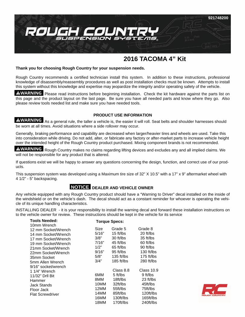
Thank you for choosing Rough Country for your suspension needs. Rough Country recommends a certified technician install this system. In addition to these instructions, professional knowledge of disassembly/reassembly procedures as well as post installation checks must be known. Attempts to install this system without this knowledge and expertise may jeopardize the integrity and/or operating safety of the vehicle.
Please read instructions before beginning installation. Check the kit hardware against the parts list on this page and the product layout on the last page. Be sure you have all needed parts and know where they go. Also please review tools needed list and make sure you have needed tools.
PRODUCT USE INFORMATION
As a general rule, the taller a vehicle is, the easier it will roll. Seat belts and shoulder harnesses should be worn at all times. Avoid situations where a side rollover may occur.
Generally, braking performance and capability are decreased when larger/heavier tires and wheels are used. Take this into consideration while driving. Do not add, alter, or fabricate any factory or after-market parts to increase vehicle height over the intended height of the Rough Country product purchased. Mixing component brands is not recommended.
Rough Country makes no claims regarding lifting devices and excludes any and all implied claims. We will not be responsible for any product that is altered.
If questions exist we will be happy to answer any questions concerning the design, function, and correct use of our prod-ucts.
This suspension system was developed using a Maximum tire size of 32” X 10.5” with a 17” x 9” aftermarket wheel with 4 1/2” - 5” backspacing.
DEALER AND VEHICLE OWNER
Any vehicle equipped with any Rough Country product should have a “Warning to Driver” decal installed on the inside of the windshield or on the vehicle’s dash. The decal should act as a constant reminder for whoever is operating the vehi-cle of its unique handling characteristics.
INSTALLING DEALER - it is your responsibility to install the warning decal and forward these installation instructions on to the vehicle owner for review. These instructions should be kept in the vehicle for its service
921748200
Tools Needed: 10mm Wrench 12 mm Socket/Wrench 14 mm Socket/Wrench 17 mm Socket/Wrench 19 mm Socket/Wrench 21mm Socket/Wrench 22mm Socket/Wrench 35mm Socket 5mm Allen Wrench 9/16” socket/wrench 1 1/4” Wrench 11/32” Drll Bit Hammer Jack Stands Floor Jack Flat Screwdriver
2016 TACOMA 4” Kit
Torque Specs:
Size Grade 5 Grade 8 5/16” 15 ft/lbs 20 ft/lbs 3/8” 30 ft/lbs 35 ft/lbs 7/16” 45 ft/lbs 60 ft/lbs 1/2” 65 ft/lbs 90 ft/lbs 9/16” 95 ft/lbs 130 ft/lbs 5/8” 135 ft/lbs 175 ft/lbs 3/4” 185 ft/lbs 280 ft/lbs Class 8.8 Class 10.9 6MM 5 ft/lbs 9 ft/lbs 8MM 18ft/lbs 23 ft/lbs 10MM 32ft/lbs 45ft/lbs 12MM 55ft/lbs 75ft/lbs 14MM 85ft/lbs 120ft/lbs 16MM 130ft/lbs 165ft/lbs 18MM 170ft/lbs 240ft/lbs
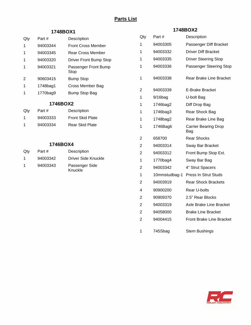
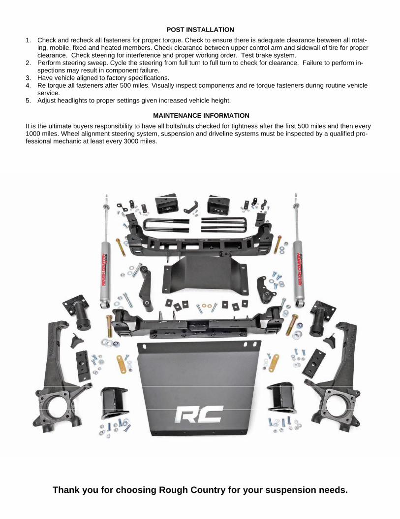
Parts List
Qty Part # Description
1 94003344 Front Cross Member
1 94003345 Rear Cross Member
1 94003320 Driver Front Bump Stop
1 94003321 Passenger Front Bump Stop
2 90603415 Bump Stop
1 1748bag1 Cross Member Bag
1 1770bag9 Bump Stop Bag
1748BOX1
Qty Part # Description
1 94003333 Front Skid Plate
1 94003334 Rear Skid Plate
1746BOX2
1748BOX2 Qty Part # Description
1 94003305 Passenger Diff Bracket
1 94003332 Driver Diff Bracket
1 94003335 Driver Steering Stop
1 94003336 Passenger Steering Stop
1 94003338 Rear Brake Line Bracket
2 94003339 E-Brake Bracket
1 9/16bag U-bolt Bag
1 1746bag2 Diff Drop Bag
1 1746bag3 Rear Shock Bag
1 1748bag2 Rear Brake Line Bag
1 1746Bag6 Carrier Bearing Drop Bag
2 658700 Rear Shocks
2 94003314 Sway Bar Bracket
2 94003312 Front Bump Stop Ext.
1 1770bag4 Sway Bar Bag
2 94003342 4” Strut Spacers
1 10mmstudbag-1 Press In Strut Studs
2 94003919 Rear Shock Brackets
4 90900200 Rear U-bolts
2 90909370 2.5” Rear Blocks
2 94003319 Axle Brake Line Bracket
2 94058000 Brake Line Bracket
2 94004415 Front Brake Line Bracket
1 745Sbag Stem Bushings
1746BOX4 Qty Part # Description
1 94003342 Driver Side Knuckle
1 94003343 Passenger Side Knuckle

Kit Bags
1748Bag1 2-5/8” x 5.5” bolts 2-5/8” nylocks 4-5/8” washers 2-22mm x 110mm bolts 2-22mm nylocks 4-22mm washers 1746Bag2 6-bushings 3-9/16” x 3/4” x 2.41” Sleeve 3-9/16” x 3.5” bolt 3-9/16” top lock 9-9/16” washer 3-14mm x 25mm bolt 6-3/8” x 1.25” bolt 6-3/8” washer 2-10mm nylock 2-10mm x 35mm bolt 1746Bag3 2-1.5” shock sleeve 2-1.25” shock sleeve 1748Bag2 7-1/4” x 3/4” bolt 14-1/4” washer 7-1/4” nuts 2-5/16” nylocks 2-5/16” x 3/4” bolt 2-3/8” nylock 4-3/8” washer 2-3/8” x 1” bolt 4-5/16” washer 1746Bag6 6-carrier bearing shims 2-hardened washers 2-10mm x 50mm bolts 1746Bag4 1-instruction sheet 1-warning to driver 2-N2.0 stickers
1770Bag9 6-3/8” self tapping bolt 9/16Bag 8-9/16” nylocks 8-9/16” washers 1770Bag4 4-5/16” washers 4-3/8” nuts 4-3/8” lock washers 4-3/8” x 1” bolt 10MMSTUDBAG-1 6-10mm Studs 6-10mm Lock Washers 6-10mm Flat Washers 7-10mm Nuts 1-.500” Jam Nut
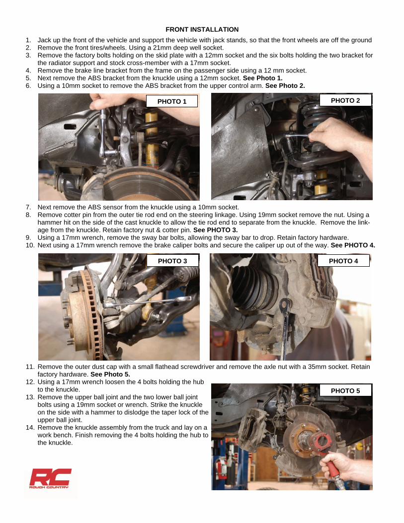
FRONT INSTALLATION
1. Jack up the front of the vehicle and support the vehicle with jack stands, so that the front wheels are off the ground 2. Remove the front tires/wheels. Using a 21mm deep well socket. 3. Remove the factory bolts holding on the skid plate with a 12mm socket and the six bolts holding the two bracket for
the radiator support and stock cross-member with a 17mm socket. 4. Remove the brake line bracket from the frame on the passenger side using a 12 mm socket. 5. Next remove the ABS bracket from the knuckle using a 12mm socket. See Photo 1. 6. Using a 10mm socket to remove the ABS bracket from the upper control arm. See Photo 2.
7. Next remove the ABS sensor from the knuckle using a 10mm socket. 8. Remove cotter pin from the outer tie rod end on the steering linkage. Using 19mm socket remove the nut. Using a
hammer hit on the side of the cast knuckle to allow the tie rod end to separate from the knuckle. Remove the link-age from the knuckle. Retain factory nut & cotter pin. See PHOTO 3.
9. Using a 17mm wrench, remove the sway bar bolts, allowing the sway bar to drop. Retain factory hardware. 10. Next using a 17mm wrench remove the brake caliper bolts and secure the caliper up out of the way. See PHOTO 4.
11. Remove the outer dust cap with a small flathead screwdriver and remove the axle nut with a 35mm socket. Retain factory hardware. See Photo 5.
12. Using a 17mm wrench loosen the 4 bolts holding the hub to the knuckle.
13. Remove the upper ball joint and the two lower ball joint bolts using a 19mm socket or wrench. Strike the knuckle on the side with a hammer to dislodge the taper lock of the upper ball joint.
14. Remove the knuckle assembly from the truck and lay on a work bench. Finish removing the 4 bolts holding the hub to the knuckle.
PHOTO 4
PHOTO 2 PHOTO 1
PHOTO 3
PHOTO 5
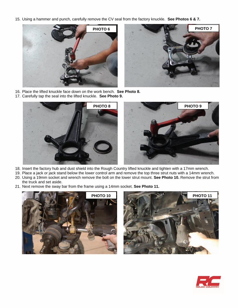
15. Using a hammer and punch, carefully remove the CV seal from the factory knuckle. See Photos 6 & 7.
16. Place the lifted knuckle face down on the work bench. See Photo 8. 17. Carefully tap the seal into the lifted knuckle. See Photo 9.
18. Insert the factory hub and dust shield into the Rough Country lifted knuckle and tighten with a 17mm wrench. 19. Place a jack or jack stand below the lower control arm and remove the top three strut nuts with a 14mm wrench. 20. Using a 19mm socket and wrench remove the bolt on the lower strut mount. See Photo 10. Remove the strut from
the truck and set aside. 21. Next remove the sway bar from the frame using a 14mm socket. See Photo 11.
PHOTO 9
PHOTO 7 PHOTO 6
PHOTO 8
PHOTO 10 PHOTO 11
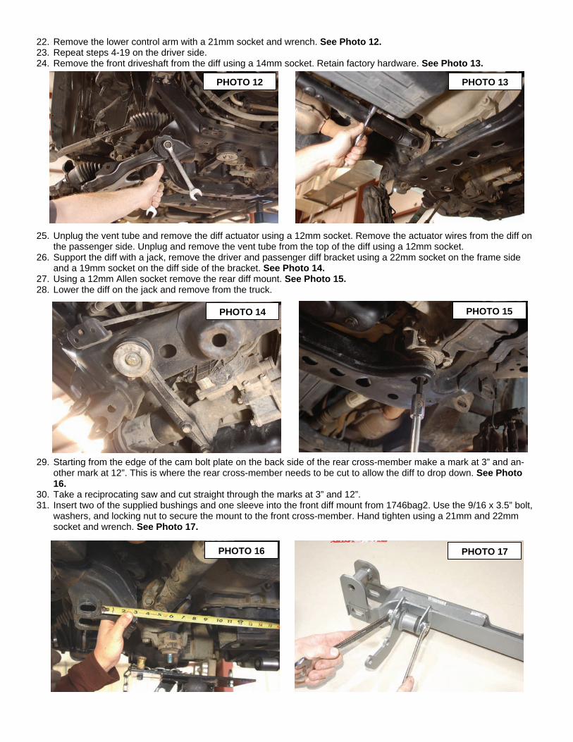
22. Remove the lower control arm with a 21mm socket and wrench. See Photo 12. 23. Repeat steps 4-19 on the driver side. 24. Remove the front driveshaft from the diff using a 14mm socket. Retain factory hardware. See Photo 13.
25. Unplug the vent tube and remove the diff actuator using a 12mm socket. Remove the actuator wires from the diff on the passenger side. Unplug and remove the vent tube from the top of the diff using a 12mm socket.
26. Support the diff with a jack, remove the driver and passenger diff bracket using a 22mm socket on the frame side and a 19mm socket on the diff side of the bracket. See Photo 14.
27. Using a 12mm Allen socket remove the rear diff mount. See Photo 15. 28. Lower the diff on the jack and remove from the truck.
29. Starting from the edge of the cam bolt plate on the back side of the rear cross-member make a mark at 3” and an-other mark at 12”. This is where the rear cross-member needs to be cut to allow the diff to drop down. See Photo 16.
30. Take a reciprocating saw and cut straight through the marks at 3” and 12”. 31. Insert two of the supplied bushings and one sleeve into the front diff mount from 1746bag2. Use the 9/16 x 3.5” bolt,
washers, and locking nut to secure the mount to the front cross-member. Hand tighten using a 21mm and 22mm socket and wrench. See Photo 17.
PHOTO 15 PHOTO 14
PHOTO 13 PHOTO 12
PHOTO 17 PHOTO 16
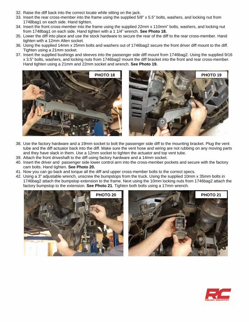
32. Raise the diff back into the correct locate while sitting on the jack. 33. Insert the rear cross-member into the frame using the supplied 5/8” x 5.5” bolts, washers, and locking nut from
1748bag1 on each side. Hand tighten. 34. Insert the front cross-member into the frame using the supplied 22mm x 110mm” bolts, washers, and locking nut
from 1748bag1 on each side. Hand tighten with a 1 1/4” wrench. See Photo 18. 35. Lower the diff into place and use the stock hardware to secure the rear of the diff to the rear cross-member. Hand
tighten with a 12mm Allen socket. 36. Using the supplied 14mm x 25mm bolts and washers out of 1746bag2 secure the front driver diff mount to the diff.
Tighten using a 21mm socket. 37. Insert the supplied bushings and sleeves into the passenger side diff mount from 1746bag2. Using the supplied 9/16
x 3.5” bolts, washers, and locking nuts from 1746bag2 mount the diff bracket into the front and rear cross-member. Hand tighten using a 21mm and 22mm socket and wrench. See Photo 19.
38. Use the factory hardware and a 19mm socket to bolt the passenger side diff to the mounting bracket. Plug the vent tube and the diff actuator back into the diff. Make sure the vent hose and wiring are not rubbing on any moving parts and they have slack in them. Use a 12mm socket to tighten the actuator and top vent tube.
39. Attach the front driveshaft to the diff using factory hardware and a 14mm socket. 40. Insert the driver and passenger side lower control arm into the cross-member pockets and secure with the factory
cam bolts. Hand tighten. See Photo 20. 41. Now you can go back and torque all the diff and upper cross-member bolts to the correct specs. 42. Using a 3” adjustable wrench, unscrew the bumpstops from the truck. Using the supplied 10mm x 35mm bolts in
1746bag2 attach the bumpstop extension to the frame. Next using the 10mm locking nuts from 1746bag2 attach the factory bumpstop to the extension. See Photo 21. Tighten both bolts using a 17mm wrench.
PHOTO 18 PHOTO 19
PHOTO 20 PHOTO 21
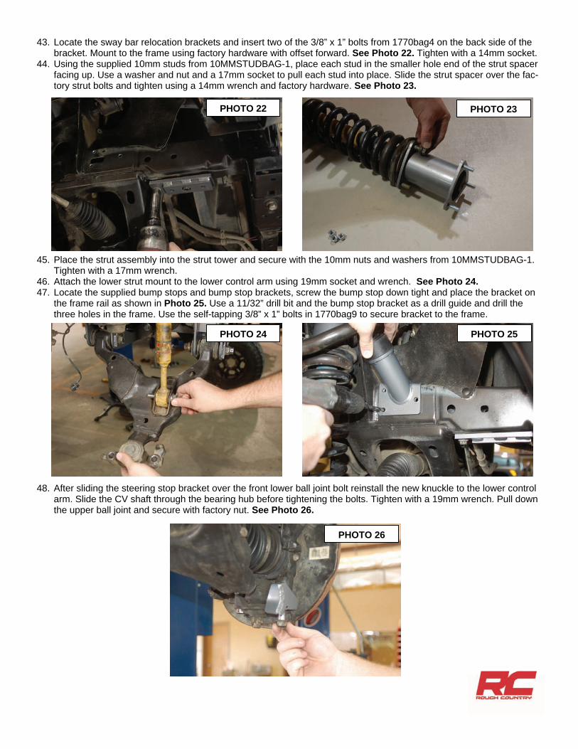
43. Locate the sway bar relocation brackets and insert two of the 3/8” x 1” bolts from 1770bag4 on the back side of the bracket. Mount to the frame using factory hardware with offset forward. See Photo 22. Tighten with a 14mm socket.
44. Using the supplied 10mm studs from 10MMSTUDBAG-1, place each stud in the smaller hole end of the strut spacer facing up. Use a washer and nut and a 17mm socket to pull each stud into place. Slide the strut spacer over the fac-tory strut bolts and tighten using a 14mm wrench and factory hardware. See Photo 23.
45. Place the strut assembly into the strut tower and secure with the 10mm nuts and washers from 10MMSTUDBAG-1. Tighten with a 17mm wrench.
46. Attach the lower strut mount to the lower control arm using 19mm socket and wrench. See Photo 24. 47. Locate the supplied bump stops and bump stop brackets, screw the bump stop down tight and place the bracket on
the frame rail as shown in Photo 25. Use a 11/32” drill bit and the bump stop bracket as a drill guide and drill the three holes in the frame. Use the self-tapping 3/8” x 1” bolts in 1770bag9 to secure bracket to the frame.
48. After sliding the steering stop bracket over the front lower ball joint bolt reinstall the new knuckle to the lower control arm. Slide the CV shaft through the bearing hub before tightening the bolts. Tighten with a 19mm wrench. Pull down the upper ball joint and secure with factory nut. See Photo 26.
PHOTO 26
PHOTO 25
PHOTO 23
PHOTO 24
PHOTO 22
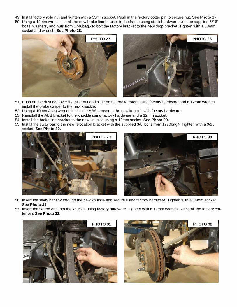
49. Install factory axle nut and tighten with a 35mm socket. Push in the factory cotter pin to secure nut. See Photo 27. 50. Using a 12mm wrench install the new brake line bracket to the frame using stock hardware. Use the supplied 5/16”
bolts, washers, and nuts from 1746bag5 to bolt the factory bracket to the new drop bracket. Tighten with a 13mm socket and wrench. See Photo 28.
51. Push on the dust cap over the axle nut and slide on the brake rotor. Using factory hardware and a 17mm wrench install the brake caliper to the new knuckle.
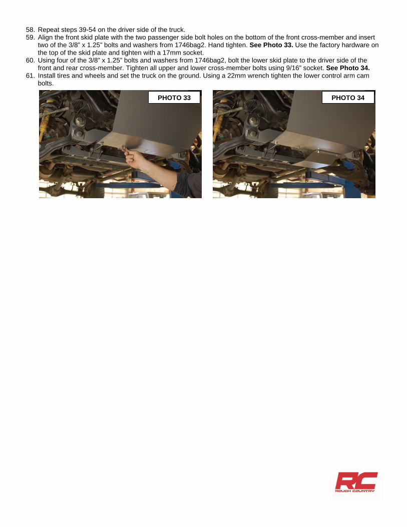
52. Using a 10mm Allen wrench install the ABS sensor to the new knuckle with factory hardware. 53. Reinstall the ABS bracket to the knuckle using factory hardware and a 12mm socket. 54. Install the brake line bracket to the new knuckle using a 12mm socket. See Photo 29. 55. Install the sway bar to the new relocation bracket with the supplied 3/8’ bolts from 1770bag4. Tighten with a 9/16
socket. See Photo 30.
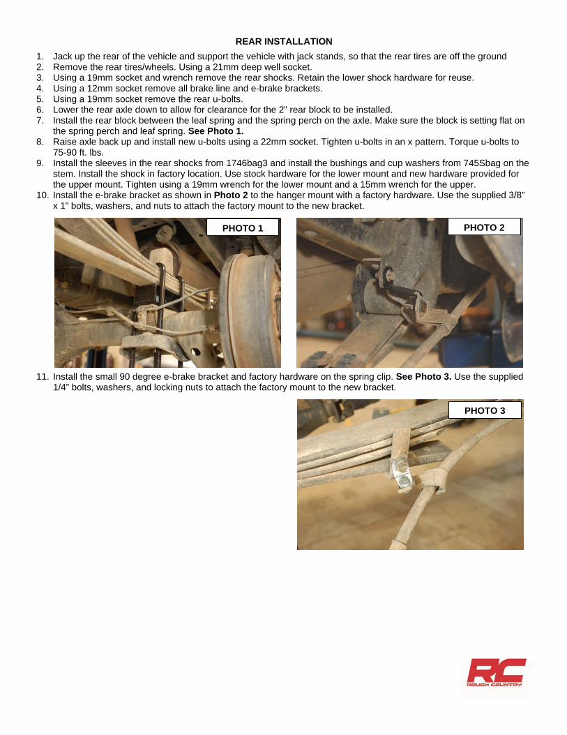
56. Insert the sway bar link through the new knuckle and secure using factory hardware. Tighten with a 14mm socket. See Photo 31.
57. Insert the tie rod end into the knuckle using factory hardware. Tighten with a 19mm wrench. Reinstall the factory cot-ter pin. See Photo 32.
PHOTO 30 PHOTO 29
PHOTO 28 PHOTO 27
PHOTO 31 PHOTO 32
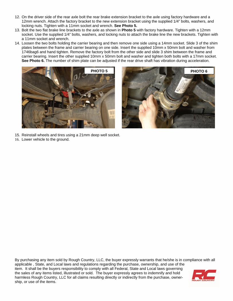
58. Repeat steps 39-54 on the driver side of the truck. 59. Align the front skid plate with the two passenger side bolt holes on the bottom of the front cross-member and insert
two of the 3/8” x 1.25” bolts and washers from 1746bag2. Hand tighten. See Photo 33. Use the factory hardware on the top of the skid plate and tighten with a 17mm socket.
60. Using four of the 3/8” x 1.25” bolts and washers from 1746bag2, bolt the lower skid plate to the driver side of the front and rear cross-member. Tighten all upper and lower cross-member bolts using 9/16” socket. See Photo 34.
61. Install tires and wheels and set the truck on the ground. Using a 22mm wrench tighten the lower control arm cam bolts.
PHOTO 33 PHOTO 34
REAR INSTALLATION
1. Jack up the rear of the vehicle and support the vehicle with jack stands, so that the rear tires are off the ground 2. Remove the rear tires/wheels. Using a 21mm deep well socket. 3. Using a 19mm socket and wrench remove the rear shocks. Retain the lower shock hardware for reuse. 4. Using a 12mm socket remove all brake line and e-brake brackets. 5. Using a 19mm socket remove the rear u-bolts. 6. Lower the rear axle down to allow for clearance for the 2” rear block to be installed. 7. Install the rear block between the leaf spring and the spring perch on the axle. Make sure the block is setting flat on
the spring perch and leaf spring. See Photo 1. 8. Raise axle back up and install new u-bolts using a 22mm socket. Tighten u-bolts in an x pattern. Torque u-bolts to
75-90 ft. lbs. 9. Install the sleeves in the rear shocks from 1746bag3 and install the bushings and cup washers from 745Sbag on the
stem. Install the shock in factory location. Use stock hardware for the lower mount and new hardware provided for the upper mount. Tighten using a 19mm wrench for the lower mount and a 15mm wrench for the upper.
10. Install the e-brake bracket as shown in Photo 2 to the hanger mount with a factory hardware. Use the supplied 3/8” x 1” bolts, washers, and nuts to attach the factory mount to the new bracket.
11. Install the small 90 degree e-brake bracket and factory hardware on the spring clip. See Photo 3. Use the supplied 1/4” bolts, washers, and locking nuts to attach the factory mount to the new bracket.
PHOTO 3
PHOTO 2 PHOTO 1
12. On the driver side of the rear axle bolt the rear brake extension bracket to the axle using factory hardware and a 12mm wrench. Attach the factory bracket to the new extension bracket using the supplied 1/4” bolts, washers, and locking nuts. Tighten with a 11mm socket and wrench. See Photo 5.
13. Bolt the two flat brake line brackets to the axle as shown in Photo 5 with factory hardware. Tighten with a 12mm socket. Use the supplied 1/4” bolts, washers, and locking nuts to attach the brake line the new brackets. Tighten with a 11mm socket and wrench.
14. Loosen the two bolts holding the carrier bearing and then remove one side using a 14mm socket. Slide 3 of the shim plates between the frame and carrier bearing on one side. Insert the supplied 10mm x 50mm bolt and washer from 1746bag6 and hand tighten. Remove the factory bolt from the other side and slide 3 shim between the frame and carrier bearing. Insert the other supplied 10mm x 50mm bolt and washer and tighten both bolts with a 17mm socket. See Photo 6. The number of shim plate can be adjusted if the rear drive shaft has vibration during acceleration.
15. Reinstall wheels and tires using a 21mm deep well socket. 16. Lower vehicle to the ground.
PHOTO 5 PHOTO 6
By purchasing any item sold by Rough Country, LLC, the buyer expressly warrants that he/she is in compliance with all applicable , State, and Local laws and regulations regarding the purchase, ownership, and use of the item. It shall be the buyers responsibility to comply with all Federal, State and Local laws governing the sales of any items listed, illustrated or sold. The buyer expressly agrees to indemnify and hold harmless Rough Country, LLC for all claims resulting directly or indirectly from the purchase, owner-ship, or use of the items.
POST INSTALLATION
1. Check and recheck all fasteners for proper torque. Check to ensure there is adequate clearance between all rotat-ing, mobile, fixed and heated members. Check clearance between upper control arm and sidewall of tire for proper clearance. Check steering for interference and proper working order. Test brake system.
2. Perform steering sweep. Cycle the steering from full turn to full turn to check for clearance. Failure to perform in-spections may result in component failure.
3. Have vehicle aligned to factory specifications. 4. Re torque all fasteners after 500 miles. Visually inspect components and re torque fasteners during routine vehicle
service. 5. Adjust headlights to proper settings given increased vehicle height.
MAINTENANCE INFORMATION
It is the ultimate buyers responsibility to have all bolts/nuts checked for tightness after the first 500 miles and then every 1000 miles. Wheel alignment steering system, suspension and driveline systems must be inspected by a qualified pro-fessional mechanic at least every 3000 miles.
Thank you for choosing Rough Country for your suspension needs.