2016 Standard for Performance Rating of Forced-circulation...
29
2016 Standard for Performance Rating of Forced-circulation Free-delivery Unit Coolers for Refrigeration AHRI Standard 420 (I-P)
Transcript of 2016 Standard for Performance Rating of Forced-circulation...

2016 Standard for
Performance Rating of Forced-circulation Free-delivery Unit Coolers for Refrigeration
AHRI Standard 420 (I-P)
©Copyright 2016, by Air-Conditioning, Heating and Refrigeration Institute
Registered United States Patent and Trademark Office
Price $10.00 (Members) $20.00 (Non-Members)
Printed in U. S.A.
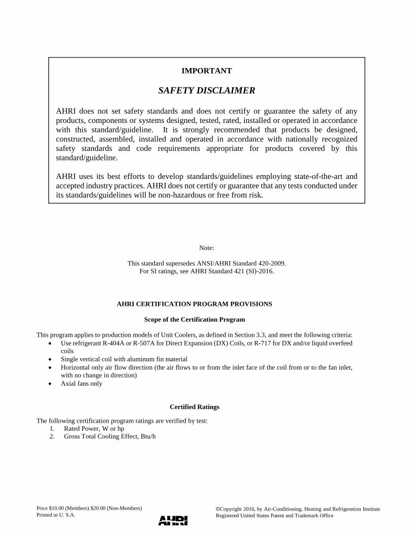
IMPORTANT
SAFETY DISCLAIMER
AHRI does not set safety standards and does not certify or guarantee the safety of any
products, components or systems designed, tested, rated, installed or operated in accordance
with this standard/guideline. It is strongly recommended that products be designed,
constructed, assembled, installed and operated in accordance with nationally recognized
safety standards and code requirements appropriate for products covered by this
standard/guideline.
AHRI uses its best efforts to develop standards/guidelines employing state-of-the-art and
accepted industry practices. AHRI does not certify or guarantee that any tests conducted under
its standards/guidelines will be non-hazardous or free from risk.
Note:
This standard supersedes ANSI/AHRI Standard 420-2009.
For SI ratings, see AHRI Standard 421 (SI)-2016.
AHRI CERTIFICATION PROGRAM PROVISIONS
Scope of the Certification Program
This program applies to production models of Unit Coolers, as defined in Section 3.3, and meet the following criteria:
Use refrigerant R-404A or R-507A for Direct Expansion (DX) Coils, or R-717 for DX and/or liquid overfeed
coils
Single vertical coil with aluminum fin material
Horizontal only air flow direction (the air flows to or from the inlet face of the coil from or to the fan inlet,
with no change in direction)
Axial fans only
Certified Ratings
The following certification program ratings are verified by test:
1. Rated Power, W or hp
2. Gross Total Cooling Effect, Btu/h
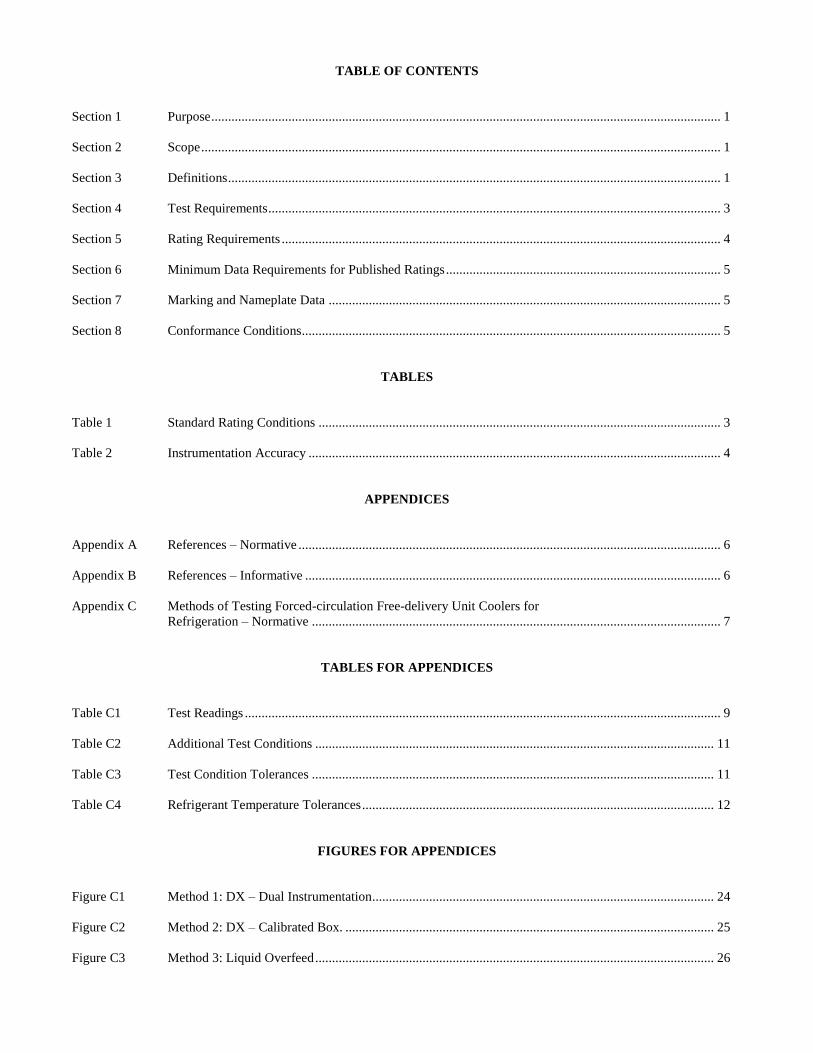
TABLE OF CONTENTS
Section 1 Purpose ........................................................................................................................................................ 1
Section 2 Scope ........................................................................................................................................................... 1
Section 3 Definitions ................................................................................................................................................... 1
Section 4 Test Requirements ....................................................................................................................................... 3
Section 5 Rating Requirements ................................................................................................................................... 4
Section 6 Minimum Data Requirements for Published Ratings .................................................................................. 5
Section 7 Marking and Nameplate Data ..................................................................................................................... 5
Section 8 Conformance Conditions............................................................................................................................. 5
TABLES
Table 1 Standard Rating Conditions ........................................................................................................................ 3
Table 2 Instrumentation Accuracy ........................................................................................................................... 4
APPENDICES
Appendix A References – Normative .............................................................................................................................. 6
Appendix B References – Informative ............................................................................................................................ 6
Appendix C Methods of Testing Forced-circulation Free-delivery Unit Coolers for
Refrigeration – Normative .......................................................................................................................... 7
TABLES FOR APPENDICES
Table C1 Test Readings .............................................................................................................................................. 9
Table C2 Additional Test Conditions ....................................................................................................................... 11
Table C3 Test Condition Tolerances ........................................................................................................................ 11
Table C4 Refrigerant Temperature Tolerances ......................................................................................................... 12
FIGURES FOR APPENDICES
Figure C1 Method 1: DX – Dual Instrumentation ...................................................................................................... 24
Figure C2 Method 2: DX – Calibrated Box. .............................................................................................................. 25
Figure C3 Method 3: Liquid Overfeed ....................................................................................................................... 26

AHRI STANDARD 420 (I-P)-2016
1
PERFORMANCE RATING OF FORCED-CIRCULATION FREE-DELIVERY UNIT COOLERS FOR REFRIGERATION
Section 1. Purpose
1.1 Purpose. The purpose of this standard is to establish for Forced-circulation Free-delivery Unit Coolers for Refrigeration:
definitions; test requirements; rating requirements; minimum data requirements for Published Ratings; marking and nameplate
data; and conformance conditions.
1.1.1 Intent. This standard is intended for the guidance of the industry, including manufacturers, engineers, installers,
contractors, and users.
1.1.2 Review and Amendment. This standard is subject to review and amendment as technology advances.
Section 2. Scope
2.1 Scope. This standard applies to factory-made, Forced-circulation, Free-delivery Unit Coolers, as defined in Section 3,
operating with a Volatile Refrigerant fed by either direct expansion or liquid overfeed at wet and/or dry conditions.
2.1.1 Exclusions. This standard does not apply to:
2.1.1.1 Air-conditioning units used primarily for comfort cooling for which testing methods are given in
other standards.
2.1.1.2 Unit Coolers operating at latent load conditions with Refrigerant Saturation Temperature < 32 ºF to
prevent frost.
2.1.1.3 Unit Coolers installed in or connected to ductwork.
2.1.1.4 Unit Coolers using zeotropic refrigerants with Glides greater than 2.0 ºF.
2.1.1.5 Field testing of Unit Coolers.
Section 3. Definitions
All terms in this document follow the standard industry definitions in the current edition of ASHRAE Terminology
(https://www.ashrae.org/resources--publications/free-resources/ashrae-terminology) unless otherwise defined in this section.
3.1 Dew Point. Refrigerant vapor saturation temperature at a specified pressure.
3.2 Enthalpy Difference (HD). The difference between the enthalpy of the air entering the Unit Cooler and the calculated
enthalpy of saturated air at the Refrigerant Saturation Temperature at the Unit Cooler outlet, Btu/lb.
3.3 Forced-circulation Free-delivery Unit Coolers (Unit Coolers). A factory-made assembly, including means for forced
air circulation and elements by which heat is transferred from air to refrigerant without any element external to the cooler
imposing air resistance. These may also be referred to as Air Coolers, Cooling Units, Air Units or Evaporators.
3.3.1 Direct Expansion Unit Cooler. A Unit Cooler in which the leaving refrigerant vapor is superheated.
3.3.2 Liquid Overfeed Unit Cooler. A Unit Cooler in which the refrigerant liquid is supplied at a Recirculation
Rate greater than 1.
3.4 Glide. The absolute value of the difference between the starting and ending temperatures of a phase-change process
(condensation or evaporation) for a zeotropic refrigerant exclusive of any liquid subcooling or vapor superheating.

AHRI STANDARD 420 (I-P)-2016
2
3.5 Gross Total Cooling Effect (Cooling Capacity). The heat absorbed by the refrigerant, Btu/h. This is the sum of the
Net Total Cooling Effect and the heat equivalent of the energy required to operate the Unit Cooler. This includes both sensible
and latent cooling.
3.6 Net Total Cooling Effect. The refrigeration capacity available for space and product cooling, Btu/h. It is equal to the
Gross Total Cooling Effect less the heat equivalent of energy required to operate the Unit Cooler. This includes both sensible
and latent cooling.
3.7 Overfeed Ratio. The mass ratio of liquid to vapor at the outlet of the Liquid Overfeed Unit Cooler. This may also be
referred to as overfeed rate.
3.8 Published Rating. A statement of the assigned values of those performance characteristics, under stated Rating
Conditions, by which a unit may be chosen to fit its application. These values apply to all units of like nominal size and type
(identification) produced by the same manufacturer. The term Published Rating includes the rating of all performance
characteristics shown on the unit or published in specifications, advertising or other literature, controlled by the manufacturer,
at stated Rating Conditions.
3.8.1 Application Rating. A rating at conditions other than Standard Rating Conditions.
3.8.2 Standard Rating. A rating at one of the Standard Rating Conditions shown in Table 1 that is an accurate
representation of test data.
3.9 Rated Power.
3.9.1 For single phase motors, total fan motor input power, W or kW.
3.9.2 For polyphase motors, individual fan motor output power, hp.
3.10 Rating Conditions. Any set of operating conditions under which a single level of performance results and which
causes only that level of performance to occur.
3.10.1 Standard Rating Conditions. Rating Conditions listed in Table 1 that can be used as a basis of comparison
for performance characteristics.
3.10.1.1 Dry Rating Condition. Rating Condition where latent cooling is not present.
3.10.1.2 Wet Rating Condition. Rating Condition where both sensible and latent cooling are present and the
coil surface temperature is above freezing.
3.11 Recirculation Ratio. (Recirculation Rate) The mass ratio of liquid circulated to the amount of liquid vaporized.
3.12 Refrigerant Saturation Temperature. Refrigerant temperature at the Unit Cooler inlet or outlet determined either by
measuring the temperature at the outlet of the two-phase refrigerant flow, for a Liquid Overfeed Unit Cooler, or by measuring
refrigerant pressure and determining the corresponding temperature from reference thermodynamic tables or equations for the
refrigerant, ºF. For zeotropic refrigerants, the corresponding temperature to a measured pressure is the refrigerant Dew Point.
3.13 “Shall” or “Should”. “Shall” or “Should” shall be interpreted as follows:
3.13.1 Shall. Where “shall” or “shall not” is used for a provision specified, that provision is mandatory if compliance
with the standard is claimed.
3.13.2 Should. “Should” is used to indicate provisions which are not mandatory but which are desirable as good
practice.
3.14 Standard Air Conditions. Dry air at 70 ºF and absolute pressure 29.92 in Hg. Under these conditions, dry air has a
mass density of 0.075 lb/ft3.
3.15 Steady-State Conditions. An operating state of a system, including its surroundings, in which the extent of change
with time is within the limits specified in Tables C3 and C4.

AHRI STANDARD 420 (I-P)-2016
3
3.16 Temperature Difference (TD). The difference between the dry-bulb temperature of the air entering the Unit Cooler
and the Refrigerant Saturation Temperature at the unit cooler outlet, ºF.
3.17 Test Measurement. The reading of a specific test instrument at a specific point in time. The Test Measurement may
be averaged with other measurements of the same parameter at the same time to determine a Test Reading or averaged over
the duration of the test to determine the value for the Test Run.
3.18 Test Reading. The recording of one full set of the Test Measurements required to assess the performance of the test
unit.
3.19 Test Run. Test Readings compiled during Unit Cooler operation during which steady-state conditions have been
maintained. It shall last for a minimum of 30 minutes with at least 15 consecutive Test Readings, all of which shall comply
with the requirements of Tables C1, C2, C3 and C4. It includes all the information required to determine Unit Cooler
performance at a specific rating condition.
3.20 Test Series. A group of Test Runs, performed on the same test unit, to determine performance at all required rating
conditions.
3.21 Volatile Refrigerant. A refrigerant which changes from liquid to vapor in the process of absorbing heat.
Section 4. Test Requirements
4.1 Test Requirements. All Standard Ratings of Unit Coolers shall be verified by tests conducted at Standard Rating
Conditions, Table 1, in accordance with one of the methods set forth in Appendix C.
Table 1. Standard Rating Conditions
Condition
Number
Coil rating
condition
Entering Air Refrigerant
Saturation
Temperature2,
ºF
Temperature
Difference,
ºF Dry-bulb
Temperature, ºF
Wet-bulb
Temperature,
ºF
Relative
Humidity1,
%
Dew Point
Temperature1, ºF
1 Wet 50 46.1 75 - 35 15
2 Dry 50 - < 45 < 30 35 15
3 Dry 35 - < 50 < 20 25 10
4 Dry 10.0 - < 46 < -5.0 0.00 10
5 Dry -10.0 - < 43 < -25 -20.0 10
Notes:
1. The coil Dry Rating Condition can be confirmed by measuring either the entering air dew point or relative humidity
according to the instrumentation requirements of Table 2. At coil Wet Rating Condition, relative humidity is for reference
only.
2. Measured at coil outlet.
4.1.1 All regularly furnished equipment that will affect performance shall be in place during the test.
4.1.2 The refrigerant used during the test shall be one that is published for use with the Unit Cooler.
4.1.3 Each Standard Rating test shall be performed at either 50 Hz or 60 Hz and at the highest rated voltage as
specified by the manufacturer on the unit or motor nameplate.
4.1.4 Instrumentation Requirements. Precision instruments and automated electronic data acquisition equipment
shall be used to measure and record temperature, pressure and refrigerant flow rate test parameters. The use of
advanced technologies or methods of measurement not described in this appendix are acceptable, provided the
accuracy requirements of this appendix are achieved by the alternative method.
AHRI STANDARD 420 (I-P)-2016
4
4.1.4.1 Calibration All measuring instruments and instrument systems (e.g. data acquisition coupled to
temperature, pressure, or flow sensors) shall be calibrated by comparison to primary or secondary standards
with calibrations traceable to National Institute of Standards and Technology (NIST) measurements, other
recognized national laboratories, or derived from accepted values of natural physical constants. All test
instruments shall be calibrated annually, whenever damaged, or when the accuracy is called into question.
4.1.4.2 Selection and Accuracy. All measuring instruments shall be selected to meet or exceed the accuracy
criteria listed in Table 2 for each type of measurement.
Table 2. Instrumentation Accuracy
Measurement Medium Minimum Accuracy Instrument Examples
Temperature
Air dry-bulb
± 0.10 °F
Resistance temperature device (RTD)
thermistor
Air wet-bulb
Refrigerant liquid
Refrigerant vapor ± 0.5 °F Special calibrated thermocouple
Air Dew Point ± 0.5 °F Chilled mirror hygrometer
Others ± 1.0 °F Liquid-in-glass thermometer
Relative Humidity1 Air ± 3 percentage points Rh Capacitive or resistive Rh sensor
Pressure
Refrigerant Pressure corresponding to ± 0.2
°F of saturation temperature Transducer
Air ± 0.05 inches of mercury Barometer
Flow
Refrigerant 1% of reading Mass flow meter
Liquids 1% of reading Venturi
Electrical
Motor
kilowatts/amperes/voltage
1% of reading
Power meter
Auxiliary kilowatt input (e.g.
heater)
Amp probe
Multimeter
Speed Motor/fan shaft 1% of reading Tachometer
Weight Oil/refrigerant solution 0.5% of reading Gravimeter (scale or analytical balance)
Specific Gravity Brine 1% of reading Hydrometer
Time Hours/minutes/seconds 0.5% of time interval Electronic clock
Note:
1. Relative humidity and air dew point measurements are intended to confirm the dry coil condition for test condition
numbers 2 through 5 from Table 1.
Section 5. Rating Requirements
5.1 Standard Ratings. Standard Ratings shall include Rated Power and Gross Total Cooling Effect established at all
applicable Standard Rating Conditions specified in Table 1.
5.2 Application Ratings. Application Ratings shall include Rated Power and Gross Total Cooling Effect at conditions
other than Standard Rating Conditions. Application Ratings with Refrigerant Saturation Temperatures below 32 ˚F shall be
rated at dry conditions. Application Ratings published by the manufacturer shall be clearly identified as Application Ratings.
5.3 Tolerances. To comply with this standard, any representative production unit selected at random, when tested at the
Standard Rating Conditions, shall have a Gross Total Cooling Effect not less than 95 % of its published Standard Rating and
not exceed 105 % of its Rated Power.

AHRI STANDARD 420 (I-P)-2016
5
Section 6. Minimum Data Requirements for Published Ratings
6.1 Minimum Data Requirements for Published Ratings. As a minimum, Published Ratings shall include all Standard
Ratings at which the unit will be produced, marketed or sold. All claims to ratings for products within the scope of this standard
shall be accompanied by the statement “Rated in accordance with AHRI Standard 420.” All claims to ratings outside the scope
of this standard shall include the statement “Outside the scope of AHRI Standard 420.” Wherever Application Ratings are
published or printed, they shall include a statement of the conditions at which the ratings apply.
6.2 Required Published Ratings. All published Standard Ratings and Application Ratings shall include:
6.2.1 Model number
6.2.2 Gross Total Cooling Effect, Btu/h
6.2.3 Temperature difference, ºF
6.2.4 Refrigerant designation(s) in accordance with ANSI/ASHRAE Standard 34 with Addenda
6.2.5 Refrigerant saturation temperature, ºF
6.2.6 Rated power, W or hp
6.2.7 Number of motors
6.2.8 Coil fin density, fins per inch or coil fin spacing; Actual fin density or fin spacing shall be within 10% of
published values.
6.2.9 Airflow rate, scfm
6.3 Recommended Published Ratings. It is recommended that the following data be published in addition to the required
Published Ratings per Section 6.2:
6.3.1 Type of defrost
6.3.2 Unit cooler motor current, A; voltage, V; and frequency, Hz
6.3.3 Defrost heater power, W; and voltage, V (if used)
Section 7. Marking and Nameplate Data
7.1 Marking and Nameplate Data. As a minimum, the manufacturer name or trade-name; model number; refrigerant(s);
current, A; voltage, V; frequency, Hz; and phase shall be shown in a conspicuous place on the unit.
Nameplate voltages for 60 Hertz systems shall include one or more of the equipment nameplate voltage ratings shown in Table
1 of AHRI Standard 110. Nameplate voltages for 50 Hertz systems shall include one or more of the utilization voltages shown
in Table 1 of IEC Standard Publication 60038.
Section 8. Conformance Conditions
8.1 Conformance. While conformance with this standard is voluntary, conformance shall not be claimed or implied for
products or equipment within the standard’s Purpose (Section 1) and Scope (Section 2) unless such product claims meet all of
the requirements of the standard and all of the testing and rating requirements are measured and reported in complete
compliance with the standard. Any product that has not met all the requirements of the standard shall not reference, state, or
acknowledge the standard in any written, oral, or electronic communication.

AHRI STANDARD 420 (I-P)-2016
6
APPENDIX A. REFERENCES – NORMATIVE
A1. Listed here are all standards, handbooks and other publications essential to the formation and implementation of the
standard. All references in this appendix are considered as part of the standard except where deviations are noted.
A1.1 AHRI Standard 110-2016, Air-Conditioning, Heating, and Refrigerating Equipment Nameplate Voltages,
2016, Air-Conditioning, Heating, and Refrigeration Institute, 2111 Wilson Boulevard, Suite 500, Arlington, VA 22201,
U.S.A.
A1.2 ANSI/ASHRAE Standard 34-2013 with Addenda, Designation and Safety Classification of Refrigerants, 2013,
American Society of Heating, Refrigerating, and Air-Conditioning Engineers, Inc., 1791 Tullie Circle, N.E., Atlanta,
GA 30329, U.S.A.
A1.3 ANSI/ASHRAE Standard 41.1-2013, Standard Method for Temperature Measurement, 2013, American
Society of Heating, Refrigerating, and Air-Conditioning Engineers, Inc., 1791 Tullie Circle, N.E., Atlanta, GA 30329,
U.S.A.
A1.4 ANSI/ASHRAE Standard 41.3-2014, Standard Method for Pressure Measurement, 2014, American Society of
Heating, Refrigerating, and Air-Conditioning Engineers, Inc., 1791 Tullie Circle, N.E., Atlanta, GA 30329, U.S.A.
A1.5 ANSI/ASHRAE Standard 41.4-2015, Standard Method for Measurement of Proportion of Lubricant in Liquid
Refrigerant, 2015, American Society of Heating, Refrigerating, and Air-Conditioning Engineers, Inc., 1791 Tullie
Circle, N.E., Atlanta, GA 30329, U.S.A.
A1.6 ANSI/ASHRAE Standard 41.10-2013, Standard Methods for Refrigerant Mass Flow Measurement Using
Flowmeters, 2013, American Society of Heating, Refrigerating, and Air-Conditioning Engineers, Inc., 1791 Tullie
Circle, N.E., Atlanta, GA 30329, U.S.A.
A1.7 ASHRAE Handbook Fundamentals, 2013, American Society of Heating, Refrigerating, and Air-Conditioning
Engineers, Inc., 1791 Tullie Circle, N.E., Atlanta, GA 30329, U.S.A.
A1.8 ASHRAE Psychrometric Analysis software, Version 7, 2016, American Society of Heating, Refrigerating, and
Air-Conditioning Engineers, Inc., 1791 Tullie Circle, N.E., Atlanta, GA 30329, U.S.A.
A1.9 ASHRAE Terminology, https://www.ashrae.org/resources--publications/free-resources/ashraeterminology,
2016, American Society of Heating, Refrigerating and Air-Conditioning Engineers, Inc., 1791 Tullie Circle, N.E.,
Atlanta, GA 30329, U.S.A.
A1.10 IEC Standard Publication 60038-2009, IEC Standard Voltages, 2009, International Electrotechnical
Commission, 3, rue de Varembé, P.O. Box 131, CH - 1211 GENEVA 20, Switzerland.
A1.11 NIST Reference Fluid Thermodynamic and Transport Properties, REFPROP, Version 9.1, 2016, National
Institute of Standards and Technology, Boulder, CO 80303, USA.
APPENDIX B. REFERENCES – INFORMATIVE
B1. Listed here are standards, handbooks, and other publications that may provide useful information and background but
are not considered essential. References in this appendix are not considered part of the standard.
B1.1 Ammonia Refrigeration Piping Handbook, 2014, International Institute of Ammonia Refrigeration, 1001 North
Fairfax Street, Suite 503, Alexandria, VA 22314, U.S.A.
B1.2 ANSI/ASHRAE Standard 41.9-2011, Standard Methods for Volatile-Refrigerant Mass Flow Measurements
Using Calorimeters, 2011, American Society of Heating, Refrigerating, and Air-Conditioning Engineers, Inc., 1791
Tullie Circle, N.E., Atlanta, GA 30329, U.S.A.

AHRI STANDARD 420 (I-P)-2016
7
APPENDIX C. METHODS OF TESTING FORCED-CIRCULATION FREE-DELIVERY UNIT COOLERS
FOR REFRIGERATION – NORMATIVE
C1. Purpose. The purpose of this appendix is to provide a method of testing for Forced-circulation Free-delivery Unit
Coolers for Refrigeration.
C2. Scope. These methods of testing apply to factory-made, Forced-circulation, Free-delivery Unit Coolers, as defined in
Section 3, operating with a Volatile Refrigerant fed by either direct expansion or liquid overfeed at wet and/or dry conditions.
C2.1 Exclusions. These methods of testing do not apply to:
C2.1.1 Air-conditioning units used primarily for comfort cooling for which testing methods are given in
other standards
C2.1.2 Unit Coolers operating at latent load conditions with Refrigerant Saturation Temperature < 32 ºF to
prevent frost
C2.1.3 Unit Coolers installed in or connected to ductwork
C2.1.4 Unit Coolers using zeotropic refrigerants with Glides greater than 2.0 ºF
C2.1.5 Field testing of Unit Coolers
C3. Measurements
C3.1 Refer to AHRI Standard 420 Table 2 for required instrumentation accuracy.
C3.2 Temperature Measurements
C3.2.1 Temperature measurements shall be made in accordance with ANSI/ASHRAE Standard 41.1.
C3.2.2 Air wet-bulb and dry-bulb temperatures entering the Unit Cooler shall be measured based on the
airflow area at the point of measurement. One measuring station is required for each 2.0 ft2 of the first 10.0 ft2
of airflow area and one additional measuring station is required for each 4.0 ft2 of airflow area above 10.0 ft2.
A minimum of two stations shall be used and the number of measuring stations shall be rounded up to the next
whole number.
C3.2.3 The airflow area shall be divided into the required number of equal area rectangles with aspect ratios
no greater than 2 to 1. Additional measuring stations may be necessary to meet this requirement. The
measuring stations shall be located at the geometric center of each rectangle.
C3.2.4 The maximum allowable deviation between any two air temperature measurement stations shall be
2.0 °F.
C3.2.5 If sampling tubes are used, each tube opening may be considered a temperature measuring station
provided the openings are uniformly spaced along the tube, the airflow rates entering each port are relatively
uniform (± 15%) and the arrangement of tubes complies with the location requirements of C3.2.3. Additionally,
a one time temperature traverse shall be made over the measurement surface, prior to the test to assess the
temperature variation and ensure it complies with the allowable deviation specified in C3.2.4. (Refer to
ANSI/ASHRAE Standard 41.1 for more information and diagrams).
C3.2.6 Refrigerant temperatures entering and leaving the Unit Cooler shall be measured by a temperature
measuring instrument placed in a thermometer well and inserted into the refrigerant stream. These wells shall
be filled with non-solidifying, thermal conducting liquid or paste to ensure the temperature sensing instrument

AHRI STANDARD 420 (I-P)-2016
8
is exposed to a representative temperature. The entering temperature of the refrigerant shall be measured within
six pipe diameters upstream of the control device.
C3.3 Pressure Measurements. Connections for pressure measurements shall be smooth and flush within the pipe
wall and shall be located not less than six pipe diameters downstream from fittings, bends, or obstructions. (Refer to
ANSI/ASHRAE Standard 41.3 for more information and diagrams).
C3.4 Volatile Refrigerant Flow Measurement
C3.4.1 Refrigerant flow meters shall be installed and the flow rate of Volatile Refrigerants shall be
measured in accordance with ANSI/ASHRAE Standard 41.10.
C3.4.1.1 Refrigerant liquid must be sub-cooled both upstream and downstream of the meter to
ensure the liquid remains single phase.
C3.4.1.2 Refrigerant vapor must be superheated both upstream and downstream of the meter to
ensure the vapor remains single phase.
C3.4.1.3 Flow meters shall be installed with at least ten pipe diameters upstream and five
diameters downstream of the meter, in straight pipe free of valves and fittings, or in accordance with
the manufacturer’s instructions.
C3.4.1.4 A direct reading mass-flow-rate measuring device, such as a Coriolis meter, is the
preferred instrument for measuring the refrigerant flow rate. Other flow meters that demonstrate
the capability to measure flow rate with the specified accuracy are also acceptable.
C3.5 Oil-in-Refrigerant Mass Ratio Measurement. The ratio of oil to refrigerant shall be less than 1 % by weight.
Unless the system does not contain refrigerant oil, tests for oil concentration shall be made a minimum of once per Test
Series per ANSI/ASHRAE Standard 41.4.
C3.6 Rated Power Measurement. Prior to conducting a capacity Test Series, the following shall be measured and
recorded, refer to Section C11.1.
E - Total electrical power input to fan motor(s) of Unit Cooler, W
FS - Fan speed (s), rpm
N - Number of motors
Pb - Barometric pressure, in Hg
Tdb - Dry-bulb temperature of air at inlet, °F
Twb - Wet-bulb temperature of air at inlet, °F
V - Voltage of each phase, V
For a given motor winding configuration, the total power input shall be measured at the highest nameplated voltage.
For three-phase power, voltage imbalance shall be no more than 2%.
AHRI STANDARD 420 (I-P)-2016
9
C3.7 Measurement Intervals. Measurement intervals shall be in accordance with Table C1.
Table C1. Test Readings
Test Parameter
Minimum Data
Collection Rate,
Test Readings per
Hour
Minimum Number
of Test Readings
per Test Run 2
Temperature 30 15
Pressure 30 15
Refrigerant mass flow rate 30 15
Test room barometric pressure 1 1
Fan speed(s) 1 1
Total electrical power input to fan motor(s)1 3 2
Total electrical power input to heater and
auxiliary equipment 1 3 2
Notes:
1. For calibrated box only (Method 2)
2. Duration of test run shall be a minimum of 30 minutes
C4. Unit Cooler General Data. The following data shall be recorded, where applicable, for each unit tested, including the
units of measurement used.
C4.1 Physical data
C4.1.1 Manufacturer name and address
C4.1.2 Identification number (model/serial)
C4.1.3 Size (external dimensions), in × in × in
C4.1.4 Nameplate motor data (for each motor)
C4.1.4.1 Type
C4.1.4.2 Frame size
C4.1.4.3 Power, hp
C4.1.4.4 Speed, rpm
C4.1.4.5 Voltage, V
C4.1.4.6 Amps, A
C4.1.4.7 Phase
C4.1.4.8 Frequency, Hz
C4.1.4.9 Efficiency (NEMA nominal or manufacturer’s certificate for polyphase motors)
C4.1.4.10 Manufacturer
C4.1.4.11 Serial number or manufacturer identification number
C4.1.5 Fan data
C4.1.5.1 Diameter, in
C4.1.5.2 Width (centrifugal fans only), in
C4.1.5.3 Speed, rpm
C4.1.5.4 Number of blades
C4.1.5.5 Manufacturer
C4.1.5.6 Model number or part number
C4.1.5.7 Number of fans

AHRI STANDARD 420 (I-P)-2016
10
C4.1.6 Cooling coil data
C4.1.6.1 Finned length, in
C4.1.6.2 Fin height and depth, in
C4.1.6.3 Number of rows deep
C4.1.6.4 Number of tubes high
C4.1.6.5 Fin density, fins per inch or fin spacing, mm based on total fin count
C4.1.6.6 If fins are staged, fin density per stage, fins per inch or fin spacing per stage
C4.1.6.7 Measured fin material thickness, in {Note: fin thickness for hot dipped galvanized
coils will vary.}
C4.1.6.8 Fin material
C4.1.6.9 Finished fin geometry
C4.1.6.10 Tube material
C4.1.6.11 Tube description {i.e. outside diameter (or equivalent), enhancements}
C4.1.6.12 Number of refrigerant circuits
C4.1.6.13 Coil or fin coatings
C4.1.7 Accessories (e.g. louvers, distributor orifice, grills)
C4.2 Specific to the test
C4.2.1 Test location, test company and address
C4.2.2 Method of test
C4.2.3 Date and time of Test Run
C4.2.4 Names of observers – responsible engineers and all data takers
C4.2.5 Published Gross Total Cooling Effect at Standard Rating Conditions, Btu/h
C4.2.6 Refrigerant
C4.2.7 Recirculation Ratio (Method 3) - manufacturer specified
C4.2.8 Refrigerant flow rate, lbm/h (Method 3) - manufacturer specified
C5. Methods of Testing. The Gross Total Cooling Effect of Unit Coolers shall be determined by one of the following
methods. In all methods, the reported Gross Total Cooling Effect, qt, shall be the average of two independent determinations.
C5.1 Method 1, DX Dual Instrumentation. The Cooling Capacity shall be determined by measuring the enthalpy
change and the mass flow rate of the refrigerant across the Unit Cooler using two independent measuring systems, see
Figure C1.
C5.2 Method 2, DX Calibrated Box. The Cooling Capacity shall be determined concurrently by measuring the
enthalpy change and the mass flow rate of the refrigerant across the Unit Cooler and the heat input to the calibrated box,
see Figure C2.
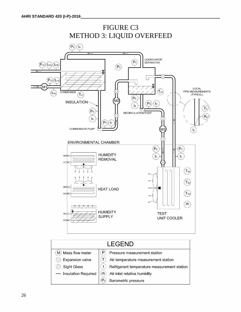
C5.3 Method 3, Liquid Overfeed. The Cooling Capacity shall be determined by measuring the enthalpy change and
the mass flow rate of the refrigerant across the Unit Cooler and also measured with a condenser calorimeter. The
refrigerant outlet pressure shall be measured and the corresponding Refrigerant Saturation Temperature shall agree with
the measured temperature within 0.2 °F. The Recirculation Ratio and refrigerant flow rate through Unit Cooler shall be
specified by the manufacturer, see Figure C3.
C6. Test Chamber Dimensions. The Unit Cooler shall be installed in a room of sufficient size to avoid airflow restrictions
or recirculation such that:
C6.1 No obstacle is positioned within a distance of AB2 from the discharge of the Unit Cooler, where A and
B are the air inlet dimensions, in, per fan section of the Unit Cooler.
C6.2 All other distances correspond to the minimum requirements of the installation instructions provided by the
manufacturer.
C6.3 The minimum volume, ft3, of the test chamber shall be 20 % of the airflow rate, ft3/min produced by the Unit
Cooler together with all auxiliary air moving devices that operate simultaneously with the Unit Cooler.

AHRI STANDARD 420 (I-P)-2016
11
C7. General Test Conditions. Test acceptance criteria listed in Tables C2, C3 and C4 apply to all methods of test:
Table C2. Additional Test Conditions
Method Condition
Number
Inlet Saturation Temperature, ºF Inlet Subcooling, ºF Outlet Superheat, ºF
Excluding R-717 R-717 only
1, 2 All 105 95 15 6.5
3
1 40 40 3 -
2 40 40 3 -
3 30 30 3 -
4 7.0 7.0 4 -
5 -10 -10 6 -
Table C3. Test Condition Tolerances
Variable Description
Test Condition Stability Over Test Run
Duration, ºF
Allowable Deviation of Average Test
Temperatures from Standard Rating
Conditions, ºF
Dry Condition Wet Condition Dry Condition Wet Condition
Dry-bulb Temperature - - ± 1.0 ± 1.0
Wet-bulb Temperature - ± 0.5 - ± 0.5
Dew Point Temperature - - Note 2 -
Temperature Difference ± 0.51 ± 0.51 - -
Refrigerant Flow Rate ± 3.0 % - -
Note:
1. The Dry-bulb temperature tolerance is set by the Temperature Difference.
2. The Dew Point Temperature cannot exceed the temperature shown in Table 1.

AHRI STANDARD 420 (I-P)-2016
12
Table C4. Refrigerant Temperature Tolerances
Variable Description
Test Temperature Stability During the Test
Run, ºF
Allowable Deviation of Average Test
Temperatures from Standard Rating
Conditions, ºF
Methods 1, 2 Method 3 Methods 1, 2 Method 3
Inlet Saturation
Temperature ± 5.0 ± 2.0 ± 2.5 ± 1.0
Inlet Subcooling ± 5.0 ± 1.0 1 ± 2.0 ± 1.0
Outlet Saturation
Temperature - - ± 0.5 ± 0.5
Outlet Superheat ± 1.5 - ± 1.0 -
Note:
1. For Test Condition 5, ± 2.0 ºF.
C8. DX Dual Instrumentation Test Procedure (Method 1)
C8.1 Test Setup and Procedure. Refer to Section C5, C6, C7 and Figure C1 for specific test setup.
C8.2 Data to be Measured and Recorded
C8.2.1 Air side (as required for dry or wet coil conditions)
FS - Fan speed (s), rpm
Pb - Barometric pressure, in Hg
rh - Air inlet relative humidity, %
Tdb - Dry-bulb temperature of air at inlet, °F
Tdp - Dew point temperature of air at inlet, °F
Twb - Wet-bulb temperature of air at inlet, °F
C8.2.2 Refrigerant side
P0a, P0b - Pressure of subcooled refrigerant liquid entering the expansion valve, psi
P2a, P2b - Pressure of superheated refrigerant vapor leaving the Unit Cooler, psi
t0a, t0b - Temperature of subcooled refrigerant liquid entering the expansion valve, °F
t2a, t2b - Temperature of superheated refrigerant vapor leaving the Unit Cooler, °F
wv1 - Mass flow rate of subcooled refrigerant liquid through M1, lbm/h
wv2 - Mass flow rate of subcooled refrigerant liquid through M2 or superheated
refrigerant vapor through M2ALT, lbm/h
C8.3 Calculations (refer to Section C11 for calculated values)
C8.3.1 For each independent refrigerant mass flow measurement at a Dry Rating Condition, calculate the
Gross Total Cooling Effect, refer to C12.1.1.
C8.3.2 For each independent refrigerant mass flow measurement at a Wet Rating Condition, calculate the
Gross Total Cooling Effect, refer to C12.1.2.
C8.3.3 Calculate the Gross Total Cooling Effect and heat balance, refer to C12.1.3 and C12.1.4.

AHRI STANDARD 420 (I-P)-2016
13
C9. DX Calibrated Box Test Procedure (Method 2)
C9.1 Test Setup and Procedure. Refer to Section C5, C6, C7 and Figure C2 for specific test setup.
C9.1.1 Apparatus Setup for Calibrated Box Calibration and Test
C9.1.1.1 The calibrated box shall be installed in a temperature controlled enclosure in which
the temperature can be maintained at a constant level.
C9.1.1.2 The temperature controlled enclosure shall be of a size that will provide clearances of
not less than 18 in at all sides, top and bottom, except that clearance of any one surface may be
reduced to not less than 5.5 in.
C9.1.1.3 In no case shall the heat leakage of the calibrated box exceed 30 % of the Gross Total
Cooling Effect of the Unit Cooler under test. The ability to maintain a low temperature in the
temperature controlled enclosure will reduce the heat leakage into the calibrated box and may extend
its application range.
C9.1.1.4 Refrigerant lines within the calibrated box shall be well insulated to avoid appreciable
heat loss or gain.
C9.1.1.5 Instruments for measuring the temperature around the outside of the calibrated box
shall be located at the center of each wall, ceiling, and floor at a distance of 6 in from the calibrated
box. Exception: in the case where a clearance around the outside of the calibrated box, as indicated
above, is reduced to less than 18 in, the number of temperature measuring devices on the outside of
that surface shall be increased to six, which shall be treated as a single temperature to be averaged
with the temperature of each of the other five surfaces. When the clearance is reduced below 12 in
(one surface only), the temperature measuring instruments shall be located midway between the
outer wall of the calibrated box and the adjacent wall. The six temperature measuring instruments
shall be located at the center of six rectangular sections of equal area.
C9.1.1.6 Heating means inside the calibrated box shall be shielded or installed in a manner to
avoid radiation to the Unit Cooler, the temperature measuring instruments, and to the walls of the
box. The heating means shall be constructed to avoid stratification of temperature, and suitable
means shall be provided for distributing the temperature uniformly.
C9.1.1.7 The average air dry-bulb temperature in the calibrated box during Unit Cooler tests
and calibrated box heat leakage tests shall be the average of eight temperatures measured at the
corners of the box at a distance of 2 in to 4 in from the walls. The instruments shall be shielded
from any cold or warm surfaces except that they shall not be shielded from the adjacent walls of the
box. The Unit Cooler under test shall be mounted such that the temperature instruments are not in
the direct air stream from the discharge of the Unit Cooler.
C9.1.2 Calibration of the Calibrated Box. A calibration test shall be made for the maximum and the
minimum forced air movements expected in the use of the calibrated box. The calibration heat leakage shall
be plotted as a straight line function of these two air quantities and the curve shall be used as calibration for
the box.
C9.1.2.1 The heat input shall be adjusted to maintain an average box temperature not less than
25.0 ºF above the test enclosure temperature.
C9.1.2.2 The average dry-bulb temperature inside the calibrated box shall not vary more than
1.0 ºF over the course of the calibration test.
C9.1.2.3 A calibration test shall be the average of eleven consecutive hourly readings when the
box has reached a steady-state temperature condition.
C9.1.2.4 The box temperature shall be the average of all readings after a steady-state
temperature condition has been reached.

AHRI STANDARD 420 (I-P)-2016
14
C9.1.2.5 The calibrated box has reached a steady-state temperature condition when:
C.9.1.2.5.1 The average box temperature is not less than 25.0ºF above the test
enclosure temperature;
C9.1.2.5.2 Temperature variations do not exceed 5.0ºF between temperature
measuring stations; and
C9.1.2.5.3 Temperatures do not vary by more than 2.0ºF at any one temperature-
measuring station.
C9.2 Data to be Measured and Recorded
C9.2.1 Air Side (as required for dry coil conditions)
E - Total electrical power input to fan motor(s) of Unit Cooler, W
FS - Fan speed (s), rpm
Pb - Barometric pressure, in Hg
rh - Air inlet relative humidity
Tcb - Average dry-bulb temperature of air within the calibrated box, °F
Tdb - Dry-bulb temperature of air at inlet, °F
Tdp - Dew point temperature of air at inlet, °F
Ten - Average dry-bulb temperature of air within the temperature controlled
enclosure, °F
Twb - Wet-bulb temperature of air at inlet, °F
C9.2.2 Heat load provided to calibrated box
Ec - Total electrical power input to heater and auxiliary equipment, W
C9.2.3 Refrigerant Side
P0 - Pressure of subcooled refrigerant liquid entering the expansion valve, psi
P2 - Pressure of superheated refrigerant vapor leaving the Unit Cooler, psi
t0 - Temperature of subcooled refrigerant liquid entering the expansion valve, °F
t2 - Temperature of superheated refrigerant vapor leaving the Unit Cooler, °F
wv1 - Mass flow rate of subcooled refrigerant liquid through M1, lbm/h
C9.3 Calculations (refer to Section C11 for calculated values)
C9.3.1 Calculate the heat leakage coefficient of the calibrated box, refer to C12.2.1.
C9.3.2 For each Dry Rating Condition, calculate the air-side Gross Total Cooling Effect, refer to C12.2.2.
C9.3.3 For each Dry Rating Condition, calculate the refrigerant-side Gross Total Cooling Effect, refer to
C12.2.3.
C9.3.4 Calculate the Gross Total Cooling Effect and heat balance, refer to C12.2.4 and C12.2.5.

AHRI STANDARD 420 (I-P)-2016
15
C10. Liquid Overfeed Test Procedure (Method 3)
C10.1 Test Setup and Procedure. Refer to Section C5, C6, C7 and Figure C3 for specific test setup.
C10.2 Data to be Measured and Recorded
C10.2.1 Air side (as required for dry or wet coil conditions)
FS - Fan speed (s), rpm
Pb - Barometric pressure, in Hg
rh - Air inlet relative humidity, %
Ta - Local pipe ambient temperature, °F
Ta1 - Condenser calorimeter ambient temperature, °F
Ta2 - Liquid/vapor separator ambient temperature, °F
Tdb - Dry-bulb temperature of air at inlet, °F
Tdp - Dew point temperature of air at inlet, °F
Twb - Wet-bulb temperature of air at inlet, °F
C10.2.2 Refrigerant side
P0 - Pressure of subcooled refrigerant liquid entering the expansion valve, psi
P3 - Pressure of saturated refrigerant liquid/vapor mixture leaving the Unit Cooler,
psi
P4 - Pressure of refrigerant in liquid/vapor separator, psi
P5 - Pressure of refrigerant entering condenser calorimeter, psi
P6 - Pressure of subcooled refrigerant liquid leaving condenser calorimeter and
entering condensate pump, psi
P7 - Pressure of subcooled refrigerant liquid leaving condensate pump, psi
P8 - Pressure of subcooled refrigerant liquid entering recirculation pump, psi
P9 - Pressure of subcooled refrigerant liquid leaving recirculation pump, psi
Pc1 - Pressure of fluid entering condenser calorimeter, psi
Pc2 - Pressure of fluid leaving condenser calorimeter, psi
t0 - Temperature of subcooled refrigerant liquid entering the expansion valve, °F
t3 - Temperature of saturated refrigerant liquid/vapor mixture at outlet, °F
t5 - Temperature of refrigerant entering condenser calorimeter, °F
t6 - Temperature of subcooled refrigerant liquid entering condensate pump, °F
t7 - Temperature of subcooled refrigerant liquid leaving condensate pump, °F
t8 - Temperature of subcooled refrigerant liquid entering recirculation pump, °F
t9 - Temperature of subcooled refrigerant liquid leaving recirculation pump, °F
tc1a, tc1b - Temperature of fluid entering condenser calorimeter, °F
tc2a, tc2b - Temperature of fluid leaving condenser calorimeter, °F
ts - Local pipe refrigerant temperature, °F
wc - Mass flow rate of fluid through M1 entering the condenser calorimeter, lbm/h
wv2 - Mass flow rate of subcooled refrigerant liquid through M2, lbm/h
wv3 - Mass flow rate of subcooled refrigerant liquid through M3, lbm/h
C10.3 Calculations (refer to Section C11 for calculated values)
C10.3.1 Calculate system heat losses or gains, refer to C12.3.1.
C10.3.2 Calculate the Recirculation Ratio, refer to C12.3.2.
C10.3.3 Calculate the condenser calorimeter capacity and mass balance, refer to C12.3.3.1 and C12.3.3.2
C10.3.4 Calculate the independent Gross Total Cooling Effect: Dry Rating Condition, refer to C12.3.3.3.
C10.3.5 Calculate the independent Gross Total Cooling Effect: Wet Rating Condition, refer to C12.3.3.4.
C10.3.6 Calculate the Gross Total Cooling Effect and heat balance, refer to C12.3.3.5 and C12.3.3.6.

AHRI STANDARD 420 (I-P)-2016
16
C10.3.7 Calculate the system heat loss or gain as a percent of the Gross Total Cooling Effect, refer to
C12.3.3.7.
C11. Calculated values. Results from these calculations are required for Section C12.
C11.1 Calculating Rated Power (all methods)
C11.1.1 Air Density for Rated Power Test
Determine the test air density (ρtest) using dry-bulb temperature (Tdb), barometric pressure (Pb) and wet-bulb
temperature (Twb) by referencing ASHRAE Psychrometric Analysis software.
C11.1.2 Rated Power, for units with single phase motors:
test
safmi
Ep
C1
C11.1.3 Rated Power, for units with polyphase motors:
N746
eEp
test
safmfmo
C2
C11.2 Average measured temperatures
C11.2.1 Dry-bulb temperature (all methods)
n
T
T
n
1ndb
db
C3
C11.2.2 Wet-bulb temperature (all methods)
n
T
T
n
wb
wb
n 1 C4
C11.2.3 Temperature of subcooled refrigerant liquid entering the expansion valve (method 1)
2
ttt b0a0
0
C5
C11.2.4 Temperature of refrigerant vapor leaving the Unit Cooler (method 1)
2
ttt b2a2
2
C6

AHRI STANDARD 420 (I-P)-2016
17
C11.2.5 Temperature of fluid entering and leaving condenser calorimeter (method 3)
2
ttt b1ca1c
1c
C7
2
ttt b2ca2c
2c
C8
C11.2.6 Temperature controlled enclosure temperature (method 2)
n
T
T
n
1nen
en
C9
C11.2.7 Calibrated box temperature (method 2)
n
T
T
n
1ncb
cb
C10
C11.3 Average measured pressures
C11.3.1 Pressure of subcooled refrigerant liquid entering the expansion valve (method 1)
2
PPP b0a0
0
C11
C11.3.2 Pressure of refrigerant vapor leaving the Unit Cooler (method 1)
2
PPP b2a2
2
C12
C11.4 Calculated Saturation Temperatures
C11.4.1 Refrigerant Liquid Saturation Temperature entering the expansion valve (all methods)
Determine t0s for P0 by referencing thermophysical properties in texts from ASHRAE Handbook Fundamentals
or NIST REFPROP.
C11.4.2 Unit Cooler Outlet Saturation Temperature (methods 1, 2)
Determine t2s for P2 by referencing thermophysical properties in texts from ASHRAE Handbook Fundamentals
or NIST REFPROP.
C11.4.3 Unit Cooler Outlet Saturation Temperature (method 3) for comparison to measured t3.
Determine t3s for P3 by referencing thermophysical properties in texts from ASHRAE Handbook Fundamentals
or NIST REFPROP.
C11.4.4 Liquid/Vapor Separator Saturation Temperature (method 3)
Determine t4s for P4 by referencing thermophysical properties in texts from ASHRAE Handbook Fundamentals
or NIST REFPROP.

AHRI STANDARD 420 (I-P)-2016
18
C11.4.5 Condenser Calorimeter Saturation Temperature (method 3)
Determine t5s for P5 by referencing thermophysical properties in texts from ASHRAE Handbook Fundamentals
or NIST REFPROP.
C11.5 Liquid subcooling entering expansion valve (all methods)
000 ttt ssc C13
C11.6 Vapor superheat leaving Unit Cooler (methods 1, 2)
s22sh2 ttt C14
C11.7 Enthalpies
C11.7.1 Air Enthalpies (methods 1, 3)
Determine enthalpies using dry-bulb (Tdb), barometric pressure (Pb) and wet-bulb (Twb) by referencing
ASHRAE Psychrometric Analysis software.
C11.7.2 Refrigerant Enthalpies
Determine enthalpies for the appropriate refrigerant by using average pressure and temperature measured at
each location and referencing thermodynamic software or texts from ASHRAE Handbook Fundamentals or
NIST REFPROP.
C11.8 Temperature Difference Correction Factor
s2dbtest tTTD (methods 1, 2) C15
s3dbtest tTTD (method 3) C16
test
rated
CFTD
TDTD C17
Refer to Table 1 for TDrated values.
C11.9 Air Enthalpy Correction Factor (methods 1, 3)
ar1arated hhHD C18
at2atest hhHD C19
test
rated
CFHD
HDHD C20
C12. Capacity Calculations for each method
C12.1 Gross Total Cooling Effect (method 1)
C12.1.1 Independent Measurement Gross Total Cooling Effect: Dry Rating Condition

AHRI STANDARD 420 (I-P)-2016
19
CF021v1tr TDhhwq C21
CF022v2tr TDhhwq C22
C12.1.2 Independent Measurement Gross Total Cooling Effect: Wet Rating Condition
CF021v1tr HDhhwq C23
CF022v2tr HDhhwq C24
C12.1.3 Gross Total Cooling Effect
2
qqq 2tr1tr
t
C25
C12.1.4 Allowable Cooling Capacity heat balance
%5q
)qq(100%5
t
2tr1tr
C26
C12.2 Gross Total Cooling Effect – Dry Rating Condition only (Method 2)
C12.2.1 Heat Leakage Coefficient of Calibrated Box
)T(T
E3.41K
cben
c
cb
C27
C12.2.2 Air-Side Gross Total Cooling Effect
CFccbencbta TDEE41.3TTKq C28
C12.2.3 Refrigerant-Side Gross Total Cooling Effect
CF021vtr TDhhwq C29
C12.2.4 Gross Total Cooling Effect
2
qqq trta
t
C30
C12.2.5 Allowable Cooling Capacity heat balance
%5q
)qq(100%5
t
trta
C31

AHRI STANDARD 420 (I-P)-2016
20
C12.3 Gross Total Cooling Effect Calculation. (Method 3)
C12.3.1 System heat loss or gain
C12.3.1.1 Condenser heat loss or gain
2
ttTkAq 6s5
1acc1c C32
C12.3.1.2 Liquid/vapor separator heat loss or gain
s42asss tTkAq C33
C12.3.1.3 Piping heat loss or gain
n
1nsnanpnpp tTkAq C34
C12.3.1.4 Pump heat gain
672vcp hhwq C35
893vrp hhwq C36
C12.3.2 Recirculation Ratio
2v
3v
w
wRR C37
C12.3.3 Gross Total Cooling Effect
C12.3.3.1 Condenser calorimeter capacity
1c2ccc hhwq C38
1c652vv qhhwq C39
1c2c
cl652vcc
hh
qhhww
C40
C12.3.3.2 Independent Gross Total Cooling Effect: Dry Rating Condition
)qqqq(TDhhwq rpcpspCF1c2cc1tr C41
)qqqq(TDhhwq rpcpspCF1c2ccc2tr C42
AHRI STANDARD 420 (I-P)-2016
21
C12.3.3.3 Independent Gross Total Cooling Effect: Wet Rating Condition
)qqqq(HDhhwq rpcpspCF1c2cc1tr C43
)qqqq(HDhhwq rpcpspCF1c2ccc2tr C44
C12.3.3.4 Gross Total Cooling Effect
2
qqq 2tr1tr
t
C45
C12.3.3.5 Allowable Cooling Capacity heat balance
%5q
)qq(100%5
t
2tr1tr
C46
C12.3.3.6 Allowable system heat loss or gain
%5q
)qqqqq(100%5
t
rpcppscl
C47
C13. Symbols and Subscripts
Ac - Surface area of exposed external area of the condenser calorimeter, ft2
Ap - Pipe surface area, ft2
As - Liquid/vapor separator surface area, ft2
E - Total electrical power input to fan motor(s) of Unit Cooler, W
Ec - Total electrical power input to heater and auxiliary equipment, W
efm - Fan motor efficiency
FS - Fan speed (s), rpm
h0 - Enthalpy of refrigerant liquid entering the Unit Cooler, Btu/lb
h2 - Enthalpy of refrigerant leaving the Unit Cooler, Btu/lb
h5 - Enthalpy of refrigerant vapor entering the condenser, Btu/lb
h6 - Enthalpy of refrigerant liquid leaving condenser calorimeter and entering condensate pump, Btu/lb
h7 - Enthalpy of refrigerant liquid leaving the condensate pump, Btu/lb
h8 - Enthalpy of refrigerant liquid leaving the liquid/vapor separator, Btu/lb
h9 - Enthalpy of refrigerant liquid leaving the recirculation pump, Btu/lb
ha1 - Enthalpy of the air entering the Unit Cooler at Standard Rating Conditions, Btu/lb
ha2 - Enthalpy of the air entering the Unit Cooler at the test condition, Btu/lb
har - Enthalpy of saturated air at Standard Rating Refrigerant Saturation Temperature, Btu/lb
hat - Enthalpy of saturated air at the test Refrigerant Saturation Temperature, Btu/lb
hc1 - Enthalpy of fluid entering the condenser, Btu/lb
hc2 - Enthalpy of fluid leaving the condenser, Btu/lb
HDCF - Enthalpy of air correction factor
HDrated - Enthalpy difference of air at Rating Conditions, Btu/lb
HDtest - Enthalpy difference of air at test conditions, Btu/lb
kc - Conductance of condenser calorimeter insulation, Btu/h·°F·ft²
Kcb - Heat leakage coefficient of calibrated box, Btu/h·°F
kp - Conductance of piping insulation, Btu/h·°F·ft²
ks - Conductance of liquid/vapor separator insulation, Btu/h·°F·ft² add dots between symbols
n - Number of measurement stations
N - Number of motors
P0 - Pressure of subcooled refrigerant liquid entering the expansion valve (method 1 average value), psi
P0a - Pressure of subcooled refrigerant liquid entering the expansion valve, psi
P0b - Pressure of subcooled refrigerant liquid entering the expansion valve, psi

AHRI STANDARD 420 (I-P)-2016
22
P2 - Pressure of superheated refrigerant vapor leaving the Unit Cooler (method 1 average value), psi
P2a - Pressure of superheated refrigerant vapor leaving the Unit Cooler, psi
P2b - Pressure of superheated refrigerant vapor leaving the Unit Cooler, psi
P3 - Pressure of saturated refrigerant liquid/vapor mixture leaving the Unit Cooler, psi
P4 - Pressure of refrigerant in liquid/vapor separator, psi
P5 - Pressure of refrigerant entering condenser calorimeter, psi
P6 - Pressure of subcooled refrigerant liquid leaving condenser calorimeter and entering condensate
pump, psi
P7 - Pressure of subcooled refrigerant liquid leaving condensate pump, psi
P8 - Pressure of subcooled refrigerant liquid entering recirculation pump, psi
P9 - Pressure of subcooled refrigerant liquid leaving recirculation pump, psi
Pb - Barometric pressure, in Hg
Pc1 - Pressure of fluid entering condenser calorimeter, psi
Pc2 - Pressure of fluid leaving condenser calorimeter, psi
pfmi - Input rated power, W
pfmo - Output rated power, hp
qc - Capacity of the condenser calorimeter calculated from the non-volatile side, Btu/h
qcl - Heat gain or loss to condenser calorimeter, Btu/h
qcp - Heat gain from condensate pump, Btu/h
qp - Total piping heat loss or gain, Btu/h
qrp - Heat gain from recirculation pump, Btu/h
qs - Heat gain or loss from liquid/vapor separator, Btu/h
qt - Gross Total Cooling Effect, Btu/h
qta - Air-side Gross Total Cooling Effect, Btu/h
qtr - Refrigerant-side Gross Total Cooling Effect, Btu/h
qtr1 - Refrigerant-side Gross Total Cooling Effect established by first independent measurement, Btu/h
qtr2 - Refrigerant-side Gross Total Cooling Effect established by second independent measurement, Btu/h
qv - Capacity of the condenser calorimeter calculated from the volatile side, Btu/h
rh - Air inlet relative humidity, %
RR - Recirculation Ratio
t0 - Temperature of subcooled refrigerant liquid entering the expansion valve (method 1 average value),
°F
t0a - Temperature of subcooled refrigerant liquid entering the expansion valve, °F
t0b - Temperature of subcooled refrigerant liquid entering the expansion valve, °F
t0s - Temperature of saturated refrigerant entering the expansion valve, °F
t0sc - Subcooling entering the expansion valve, °F
t2 - Temperature of superheated refrigerant vapor leaving the Unit Cooler (method 1 average value), °F
t2a - Temperature of superheated refrigerant vapor leaving the Unit Cooler, °F
t2b - Temperature of superheated refrigerant vapor leaving the Unit Cooler, °F
t2s - Temperature of saturated refrigerant leaving Unit Cooler, °F
t2sh - Amount of superheat leaving test Unit Cooler, °F
t3 - Temperature of refrigerant liquid/vapor leaving the Unit Cooler, °F
t3s - Temperature of saturated refrigerant leaving Unit Cooler, °F
t4s - Temperature of saturated refrigerant in liquid/vapor separator, °F
t5 - Temperature of refrigerant entering condenser calorimeter, °F
t5s - Temperature of saturated refrigerant entering condenser calorimeter, °F
t6 - Temperature of subcooled refrigerant liquid entering condensate pump, °F
t7 - Temperature of subcooled refrigerant liquid leaving condensate pump, °F
t8 - Temperature of subcooled refrigerant liquid entering recirculation pump, °F
t9 - Temperature of subcooled refrigerant liquid leaving recirculation pump, °F
Ta - Local pipe ambient temperature, °F
Ta1 - Condenser calorimeter ambient temperature, °F
Ta2 - Liquid/vapor separator ambient temperature, °F
tc1 - Average temperature of fluid entering condenser calorimeter, °F
tc1a - Temperature of fluid entering condenser calorimeter, °F
tc1b - Temperature of fluid entering condenser calorimeter, °F
tc2 - Average temperature of fluid leaving condenser calorimeter, °F
tc2a - Temperature of fluid leaving condenser calorimeter, °F
tc2b - Temperature of fluid leaving condenser calorimeter, °F

AHRI STANDARD 420 (I-P)-2016
23
Tcb - Average dry-bulb temperature of air within the calibrated box, °F
Tdb - Average dry-bulb temperature of air entering Unit Cooler, °F
Tdp - Dew point temperature of air entering Unit Cooler, °F
Ten - Average dry-bulb temperature of air within the temperature controlled enclosure, °F
ts - Local pipe refrigerant temperature, °F
Twb - Wet-bulb temperature of air entering Unit Cooler, °F
TDCF - Temperature Difference correction factor
TDrated - Temperature Difference at Rating Conditions, °F
TDtest - Temperature Difference at test conditions, °F
V - Voltage of each phase, V
wc - Mass flow rate of fluid through M1 entering the condenser calorimeter, lbm/h
wcc - Calculated mass flow rate of fluid through M1 entering the condenser calorimeter, lbm/h
wv1 - Mass flow rate of subcooled refrigerant liquid through M1, lbm/h
wv2 - Mass flow rate of subcooled liquid or superheated refrigerant vapor through M2 or M2ALT, lbm/h
wv3 - Mass flow rate of subcooled refrigerant liquid through M3, lbm/h
Greek Symbols
ρsa - Density of air at Standard Air Conditions, 0.075 lb/ft3
ρtest - Density of air at test conditions, lb/ft3
Conversion factors
1 hp = 746 W
1 W = 3.41 Btu/h
AHRI STANDARD 420 (I-P)-2016
24
FIGURE C1
METHOD 1: DX – DUAL INSTRUMENTATION

AHRI STANDARD 420 (I-P)-2016
25
FIGURE C2
METHOD 2: DX – CALIBRATED BOX
AHRI STANDARD 420 (I-P)-2016
26
FIGURE C3
METHOD 3: LIQUID OVERFEED