2016 IRC Measurement Manual
30
IRCMEAS15-1 150112 1 January 2015 IRC MEASUREMENT 1. Introduction This version, IRCMEAS16-1, has been revised and re-issued in January 2016. 2. General The guide is intended to ensure good and consistent measurement practice by IRC measurers around the world. In addition to describing each measurement, some of the common mistakes and errors are noted. While the term ‘measurer’ will be used throughout, this should be taken to include ‘official’ measurers and also owners self measuring their own boats. Official Measurers should note the following: You are measuring a boat for the owner, BUT on behalf of the rest of the fleet. The aim is thus to achieve a fair and accurate result, rather than the optimum result for the particular owner. These are not necessarily the same thing.. A professional approach and attitude is also very important. The owner is paying for your services, and wants to have confidence in the measurements you take, both on his own boat and also on his competitors' boats. This cannot be emphasised sufficiently; whilst the owner you are dealing with may be scrupulously fair, he is certain that his opposition are anything but. He needs the confidence that you will not let them get away with it! In this context, if you are not sure refer to the rule book or contact the IRC Rating Authority (via your local IRC Rule Authority) for clarification. Always explain what you are doing and show the owner the measurement outcome, particularly if it is not in his favour! He is going to get an unpleasant surprise anyway when his certificate arrives; better that he should know there and then and understand why. Measurers should NOT however discuss the effect on TCC of changes. Owners should be advised to contact the IRC Rating Authority through their Rule Authority. In the particular case of measurement for Endorsement, owners and/or measurers should contact their local IRC Rule Authority first and direct the owner to an official measurer. A specific point to note:. We have had a couple of cases recently where owners have been misled by unofficial comments by measurers. Official measurers should NEVER interpret IRC rules. If an owner asks you to interpret, or you are in doubt, contact the IRC Rating Authority through your local Rule Authority. Measurers do not have the authority to interpret IRC Rules. That right lies solely with the IRC Rating Authority. 3. Documentation Measurers will need to have available to them: Document Source IRC measurement documentation http://www.ircrating.org/technical-a-certification/measurement IRC Rules http://www.ircrating.org/technical-a-certification/rule-a-definitions ISAF ERS http://www.sailing.org/documents/equipmentrules/index.php
Transcript of 2016 IRC Measurement Manual

IRCMEAS15-1 150112 1 January 2015
IRC MEASUREMENT 1. Introduction This version, IRCMEAS16-1, has been revised and re-issued in January 2016. 2. General The guide is intended to ensure good and consistent measurement practice by IRC measurers around the world. In addition to describing each measurement, some of the common mistakes and errors are noted. While the term ‘measurer’ will be used throughout, this should be taken to include ‘official’ measurers and also owners self measuring their own boats. Official Measurers should note the following:
You are measuring a boat for the owner, BUT on behalf of the rest of the fleet. The aim is thus to achieve a fair and accurate result, rather than the optimum result for the particular owner. These are not necessarily the same thing.. A professional approach and attitude is also very important. The owner is paying for your services, and wants to have confidence in the measurements you take, both on his own boat and also on his competitors' boats. This cannot be emphasised sufficiently; whilst the owner you are dealing with may be scrupulously fair, he is certain that his opposition are anything but. He needs the confidence that you will not let them get away with it! In this context, if you are not sure refer to the rule book or contact the IRC Rating Authority (via your local IRC Rule Authority) for clarification. Always explain what you are doing and show the owner the measurement outcome, particularly if it is not in his favour! He is going to get an unpleasant surprise anyway when his certificate arrives; better that he should know there and then and understand why. Measurers should NOT however discuss the effect on TCC of changes. Owners should be advised to contact the IRC Rating Authority through their Rule Authority.
In the particular case of measurement for Endorsement, owners and/or measurers should contact their local IRC Rule Authority first and direct the owner to an official measurer. A specific point to note:. We have had a couple of cases recently where owners have been misled by unofficial comments by measurers. Official measurers should NEVER interpret IRC rules. If an owner asks you to interpret, or you are in doubt, contact the IRC Rating Authority through your local Rule Authority. Measurers do not have the authority to interpret IRC Rules. That right lies solely with the IRC Rating Authority. 3. Documentation Measurers will need to have available to them: Document Source IRC measurement documentation http://www.ircrating.org/technical-a-certification/measurement IRC Rules http://www.ircrating.org/technical-a-certification/rule-a-definitions ISAF ERS http://www.sailing.org/documents/equipmentrules/index.php
IRCMEAS16-1 160107 2 January 2016
Now that IRC Rules incorporate ERS, we have adopted the convention used within ERS that a word printed in IRC Rules in bold is being used in its ERS defined sense. This has then been extended such that a word printed underlined is being used in its IRC defined sense. IRC definitions are contained within IRC Rules as Appendix A. ERS definitions are not repeated in IRC Rules. Apart from direct quotes from IRC Rules or definitions, this convention has NOT been followed in this manual 4. Equipment With the exception of weighing, nothing complicated is needed! If full measurement is the target, the following will be required. Other bits and pieces may also be desirable. Essential: Steel tape measures: 5m and 30m (50 metres for large boats) Wooden (floating!) rulers: 1m and single hinge 2m Spirit level with 450 bevel: 0.5m (minimum) 2 plumb bobs Sundry string Desirable: 3, 8 and/or 10m steel tape measure 2m multiple hinge wooden ruler 2 more plumb bobs 0.15m - 0.20m spirit level Callipers Optical or laser level Basic tools: pliers, screwdriver, PVC tape, masking tape 5. Accuracy IRC Rule 8.10 states 8.10 Rated Dimensions 8.10.1 Values stated on certificates for LH, Hull Beam, Draft, x, P, E, J, FL, MUW, MTW,
MHW, LLmax, HSA, PY, EY, LLY, LPY, SPA and STL are maximum values. 8.10.2 Values stated on certificates for Boat Weight, BO, h, SO, y, and Internal Ballast
are minimum values. 8.10.3 If during Equipment Inspection by an Equipment Inspector, or during
measurement carried out under Rules 10.2 or 13.6, any rated dimension is found to exceed a maximum value or to be less than a minimum value, then the boat is not in compliance with her certificate.
8.10.4 Attention is drawn to Rule 13 and to RRS 78, Compliance with Class Rules;
Certificates. This defines clearly when a boat is not in compliance with her certificate. It is relevant to a measurer acting as an Equipment Inspector at an event. The introduction to IRC Rule 9 states: 9 Rating review
Rule 9 does not apply to equipment inspection at an event. In a few instances in the past, attempts have been made to take the protest limits of IRC Rule 9.8 as measurement ‘tolerances’. In other words, measured linear dimensions are adjusted by the protest limits. This is NOT the purpose of IRC Rule 9.8. Measurers shall report the actual measurements found which will be used for rating the boat. To be clear, who applies IRC Rule 9? Answer: the Rating Authority. Who applies IRC Rule 10 (which refers to IRC Rule 9)? Answer: the Protest Committee and the Rating Authority. A measurer never has any decision to take in the application of IRC Rules 9 nor 10.
IRCMEAS16-1 160107 3 January 2016
The measurer's aim must always be to achieve the best possible result. It should also be noted that in the case of a 'composite' measurement, (LWP for example), the final accuracy is dependent on the accuracy of the component parts. To demonstrate: if LOA, BO and SO all have errors of 50mm, then LWP could be in error by as much as 150mm. Unlikely perhaps, but to be borne in mind by the measurer. This issue is relevant also to the equipment used. When weighing for example, ensure that the accuracy of the equipment is sufficient. The IRC Rating Authority uses load cells with a quoted accuracy of +/-0.2% of maximum capacity, ie, for a 10 tonne cell +/-20 kg, or for a 20 tonne cell, +/-40 kg. As a rule of thumb, a load cell should not be used to weigh a boat with a weight of less than a minimum of 15% of the cell's capacity. Inevitably, this ‘rule’ has to be breached on occasion. Similarly, the Rating Authority uses EC Class II tape measures. 6. Techniques Please note the following pointers to good measuring practice: Ensure horizontal measurements are actually horizontal. For instance, when measuring from a reference point to a plumb line, hold the end of the tape on the reference point and arc the tape behind the plumb line looking for the minimum figure. Ensure vertical measurements are actually vertical. For instance, when measuring draft ashore, allow the tape to hang freely. If it does not hang above your lower reference point, move so that it does. When measuring to a plumb line, hold the tape behind the plumb line. The required measurement is then clearly marked by the tape. Never measure between two plumb lines, always between each plumb line and a fixed reference point. Be very aware of the environment, particularly the effect of wind and/or current on plumb lines and free hanging tapes. On a windy day, use a weight to steady the tape. Never attempt to identify the waterline (eg for draft or overhangs) by reference to for example discoloured anti-fouling. This is firstly inaccurate in itself, and secondly may be misleading if the boat was not floating in the correct trim. Whenever possible repeat a measurement, including any setting up. This practice is a good example of not only doing a good job, but being seen to do so by the owner. His confidence will be affected not by your measurement but by the presentation of your measurement. 7. Previous Measurements Many boats will have had either IMS (ORCi), ORC Club, or certificates under other local measurement rules in the past. With care, some of the figures on the most up to date certificate may be directly useable. Others will require checking. In general, hull measurements will not have changed, unless the boat has been modified. Others, such as rig and sail measurements will often need physically checking. Care should be taken to ensure that the data on a boat’s certificate under another rule is real data as opposed to ‘class standard’ data which may be the case under for instance ORC Club and some local rules. Additionally, IRC definitions are in many cases not the same as definitions under other rules. Great care should be exercised in this respect. The following may be used as a guide: IRC IMS/ORCi Comment Values likely to be unchanged: LH LOA Hull Beam BMax Unlikely to change, but
has been known. Engine weight EW
IRCMEAS16-1 160107 4 January 2016
J J See 2011 IRC Rule change
Values which may have changed: STL SPL Note that IRC defines
STL differently P P E E Draft D May have changed,
either as result of keel modifications or re-ballasting.
Sail data Various Note variation in definitions of dimensions.
8. Weighing The weight of boats causes possibly the most dispute of any measurement; while an apparently simple procedure, it occasionally results in wildly anomalous figures. In most cases, this can be ascribed to inadequate weighing equipment. When weighing for Endorsement purposes, measurers should refuse to use a load cell that has not been cleared by the IRC Rating Authority or the local IRC Rule Authority. Obviously, an officially owned load cell is to be preferred whenever possible. Experience over the years has shown that weighings using officially owned or sanctioned equipment are close to 100% reliable. When other load cells are used, of the order of 50% of weighings are subsequently proved to be inaccurate! When a boat is weighed, the overhangs should always be measured simultaneously. A weighing report should be produced defining what was on board and what was not, quantity of fuel and water, and overhang measurements. The IRC Rating Authority’s strongly preferred method of weighing is hanging the boat from a single point beneath a load cell. This may be either using a boat’s built in lifting point or straps around the hull with or without a lifting frame/spreader bars. Provided that the weight of whatever lifting gear is used is tared off, it doesn’t matter which. Experience over the years has shown that single point lifting to be by far the most reliable and repeatable method of weighing boats. An alternative acceptable method is the use of 3 or 4 compression load cells to weigh the gross weight of the boat in a cradle. By then deducting the weight of the cradle, boat weight can be found. This method can produce good results, but is more susceptible to error by way of missing straps, and other equipment. It is also a composite measurement, with all the inherent possibilities for error. Good measurement practice is essential. Please see Appendix 1 and discuss the method intended with the local IRC Rule Authority before going ahead. For very large boats, generally longer than 30.5m, the Rating Authority may approve calculation of weight from freeboards. See Appendix 2 for more information. Currently weighing a boat hung in a travel lift rolled onto compression load cells is NOT an approved method of weighing. The Rating Authority is experimenting with a view in the future to permitting this method. To date however the results have not proved sufficiently reliable. Historically, weighing on compression load cells was generally acceptable for an endorsed certificate. With effect from 2010, for the purposes of endorsement, this method has been moved to ‘at the discretion of a Rule Authority’. This change was made firstly as a result of concerns over general reliability and secondly because the local IRC Rule Authority is the only body in a position to properly review the proposed process in each case. What is NOT acceptable is recording the load in each sling of a travel lift by either load cell or the travel lift’s in-built equipment. The latter particularly has been shown to be capable of errors of up to 50%! The former is erroneous to the extent that the slings are not vertical, either athwartships or fore and aft. Simple geometry shows that very small errors in sling angles rapidly combine to produce gross errors.
IRCMEAS16-1 160107 5 January 2016
For very large boats (generally weighing in excess of 20 tonnes) for which weighing is impractical, an acceptable alternative is flotation followed by calculation and declaration of weight by the Rating Authority. The Rating Authority may delegate this task to the designer. If this approach is to be taken, the IRC Rating Authority must first be contacted to discuss the proposed method. Attention is drawn to the table in paragraph 4 of Appendix 4, IRC Endorsement. This clearly defines the various acceptable methods of establishing the weight of a boat and also those methods which are not acceptable. There are a number of traps the measurer can fall into. It is absolutely essential that the boat is EMPTY (see measurement condition in IRC rule 17). The measurer must be pedantic, inspecting every locker, lifting every board, and insisting on the removal of EVERYTHING, down to the toilet rolls. Among things to watch for are: • Bilges full of water. • Mainsail on the boom. • Anchors 'forgotten' under bunks. • Water fuel and holding tanks. Watch for second (and third and fourth….!) water tanks. • Chart tables full of charts and other rubbish. • Portable electronic equipment (laptop computers etc.) • Safety gear: horseshoe rings and Dan buoys on the transom. • Gas bottles (and spares!). • Fire extinguishers. • Are removal cockpit boxes on board? • Fenders and mooring lines as the boat is lifted. • Running rigging shall be slack. Do not treat the above as exhaustive. Vigilance is the only answer. It should be noted in the weighing report cushions that were on board or not on board and if removable cockpit boxes were on board or not. The number of batteries on board should also be noted. Water and holding tanks should be pumped dry. From 2013, it has been clarified that water ballast tanks shall also be empty. Fuel is more difficult and it is acceptable to deduct a known weight of fuel from the gross weight. If doing the latter, 2 means of estimating quantity should be sought. For instance a fuel gauge, and a measurement of tank volume together with either dipping the tank or a sight glass. Diesel has a specific gravity of 0.85, ie 1 litre weighs 0.85 kg. The only loose items aboard should now be fitted (but not necessarily fixed) bunk cushions, loose bunk boards, floor boards and washboards, and spinnaker pole(s). Make a note of the number of loose cushions for our records. Note also the number, identification if possible, and size of batteries (if there are an unusually large number of batteries, check that they are actually connected!), and the quantity of internal ballast. In the case of production boats any deviations from standard, eg addition/removal of furniture such as doors and tables should also be noted. Having emptied the boat, the weight of lifting gear below the load cell (ie spreader bars, straps, shackles, etc.) must be found for deduction from the gross weight. Unless using an internal centre lift point, if the boat is to be lifted from the water, the slings should first be immersed. On some load cells, this weight can be zeroed out. It is left to the measurer’s discretion whether he does this or notes the reading for later deduction. The boat should now be weighed twice, with all weight removed from the load cell between weighings. If any significant (+/-10kg) difference is seen, STOP AND FIND THE PROBLEM. Re-weigh the strops etc. to check finally that nothing has shifted. Again if any significant difference is seen STOP AND FIND THE PROBLEM.
IRCMEAS16-1 160107 6 January 2016
Be rigorous in recording everything, and input all weights, notes and comments. Please do NOT 'adjust' the figures. So what goes wrong? Obviously, equipment still aboard will not help! There are however also many more subtle things. Wind and rain can have noticeable effects. Directly, wet decks and topsides can hold significant quantities of water. Wind will also always increase the figure read. Ideally, weighing should be carried out in light winds, preferably 10 knots or less and dry weather. It is recognised however that this will often not be practical. With care, satisfactory results can be achieved in stronger winds. It is also sometimes possible to find a sheltered location. It is therefore left entirely to the discretion of measurers when to abandon a weighing because of conditions. Measurers must always report actual conditions to the IRC Rating Authority. The shackles for the load cells have to be carefully sized, not only for strength, but for match to the holes in the load cell. A minimum freedom of movement has to be allowed, otherwise any torsion or twist when lifting will be directly transmitted into the load cell, giving a potentially erroneous answer. If too much freedom of movement is given, the measurement can also be wrong. Load cell battery level is also important. If in doubt, change or charge the batteries. The load cells can be susceptible to temperature changes, care should be taken to avoid large temperature changes prior to weighing i.e. storing in a warm office prior to weighing on a cold day or a cold (air conditioned) areas before weighing in hot climates. When arriving on site open up the load cell and set up to allow as much acclimatisation as possible. When noting the weight of strops etc, read the sign (+ or -) on the display. Negative values are quite possible if the display has not been zeroed before use. Please also note that the IRC Certificate now also includes Bulb Weight for boats with keel types 10, 11 and 12. How to establish this, if needed is detailed in Appendix 9. 9. Hull 9.1 LH This is best done ashore. Owners should be informed in advance that the boat has to be set up level with the waterplane in Measurement Condition, which is a task that has to be performed before the measurer arrives. Hang plumb bobs on the centreline over the bow and stern. Measure from a convenient point on the keel or underbody to each plumb line and total for LH. DO NOT: Include pulpits, pushpits, stemhead fittings, runner/backstay tangs, bowsprits, etc. DO NOT: Measure LH with the boat out of level fore and aft. You will get the wrong answer. On
occasion, measurers may find that a boat has been deliberately levelled bow up to minimise measured LH. Measurers are quite within their rights to require that the boat be re-levelled.
If necessary, LH can be measured afloat by dividing the boat into convenient sections, measuring each and totalling. Eg: (Stem to mast) + (mast) + (mast to forward face of cockpit), etc. If doing this, be careful and check that reference vertical surfaces are actually vertical. 9.2 Hull Beam Inspect for maximum hull beam station by sighting from off the boat. It is very desirable to do this from both ahead and astern of the boat if possible. It is easy to be fooled by the shape of the boat! Maximum beam is nearly always further aft than you think. If in doubt, check several stations to find a maximum value. Having found the right station:
IRCMEAS16-1 160107 7 January 2016
If afloat: Using a level held vertically at the point of maximum hull beam (ignoring rubbing strakes)
measure inboard to a convenient point on the deck of the boat. Repeat from the other side. This method is not recommended as it is far less precise than ashore.
If ashore: Hang plumb bobs at the required station and measure in from each to a reference point
on the hull or keel. Again, NEVER measure directly between two plumb lines. 9.3 Draft The boat will need to be seen by the measurer both ashore and afloat. It doesn't matter which is first. It is better to start ashore to determine the lowest point of the keel As with overhangs, draft is measured in IRC measurement condition (see IRC Rule 17) . Ashore: Ensuring first that the boat is in level trim, establish a convenient reference point on each
side of the boat above the waterline in way of the section at maximum keel depth. Using a spirit level, project horizontally from the underside of the keel outboard to vertically below the reference point each side. Measure vertically down from each reference point. Alternatively, if available, a surveyor's level may be used.
If measuring a drop keel boat, measurements will be needed with the keel fully up and fully down.
Afloat: Ensure first that the boat is in measurement condition (IRC rule 17), that everybody is off
the boat(!), and that the boat is in level trim both fore and aft and athwartships. If doing the afloat measurement first, mark the reference points on the hull as above.
Using a wooden ruler, measure vertically downwards from the reference point each side to the water surface. By subtraction from the ashore figures, and then averaging the results, draft is found.
9.4 Overhangs Please refer to the attached diagrams before taking any measurements. Before an IRC certificate can be issued, BO, SO, y, x, and h are required for EVERY BOAT. The boat should first be inspected to ensure she is, as required by IRC rule 18, in measurement condition (rule 17). Bow overhang is usually straightforward. Stern overhang can be difficult. These measurements can only sensibly be taken in still water. Any current will offset the plumb line positions; even small waves can make an accurate stern overhang measurement very difficult. Note that on boats with skegs, stern overhang is measured to the intersection of the actual hull (the canoe body) with the water, ignoring the skeg. If the upper end of the rudder is above the waterline, it is preferable to measure SO on both sides. Hang a plumb line over the bow and stern, ensuring that they are on the centreline and do not include any hull fittings. Bow (BO): Using a floating ruler, position one end of the ruler against the bow at the waterline. Pivot
the rule about this point towards the plumb line. Repeat as many times as is necessary to achieve a consistent result.
Stern (SO): Measurement can be difficult, particularly with modern designs with transoms low to the
water. A dinghy or float is essential with an assistant to hold this in position. As with the bow, position the end of a floating ruler against the required measurement point and pivot the ruler about this point towards the plumb line. Repeat as many times as necessary to achieve a consistent result.
y: In all cases, the dimension 'y' should also be supplied. Measurement is straightforward.

IRCMEAS16-1 160107 8 January 2016
x and h: If the boat has a flying bow, measure also x and h. The diagrams define the exact
measurement points. x can be awkward to measure. h is straightforward once the measurement point has been established. If there is no flying bow, please say so and input 0 figures for x and h
As an alternative to direct measurement of BO, x and SO, if the bow and stern profiles are known (or have been measured ashore), then measurements of y and h (the easier and more accurate measurements to take directly) can be used to find BO, x and SO by either calculation or graphical methods.
Bow and stern overhangs
Waterplane
Waterplane
BO
45°
xBO
h
FLYING BOW OR KNUCKLE EXPOSED
x and h both zeroIMMERSED KNUCKLE
Waterplane
BOTRADITIONAL BOW
SO
y
COUNTER STERN
Waterplane
SO
y
SPADE RUDDER
Waterplane
TRADITIONAL TRANSOM HUNG RUDDER
Waterplane
y
SOSO
y
MODERN TRANSOM HUNG RUDDER
Waterplane
45°
x
h
10. Spars Spar and rig measurements are straightforward. P and E are exactly as other rules, with the exception that if there are no measurement bands, P is measured from the top surface of the boom or boom track to the halyard shackle pin when the halyard is fully hoisted, and E is measured from the aft face of the mast to the extremity of the boom. Hoisting a tape on the main halyard and judging its position by eye from on deck is not an accurate method. For Endorsed certificates, this is NOT acceptable. If the rig is up, sending a man aloft with the tape is the only method.

IRCMEAS16-1 160107 9 January 2016
With effect from December 2010, an IRC definition of Forestay has been added and the definitions of J and FL amended to read: Forestay The ERS definition of forestay shall not apply. Forestay is defined as: Permanently
attached rigging providing forward support for a mast spar. FL The forestay length measured from the forward end of J to the forestay rigging point. (Note: The forestay length is a maximum value, conformation should be sought from the owner/representative to confirm the forestay is in its maximum sailing length setting) J The longitudinal distance between the intersection of the fore side of the mast spar,
extended as necessary, and the deck including any superstructure; and the intersection of the centreline of the forestay, extended as necessary, and the deck, or bowsprit spar.
The substantive effect of these changes is that FL and J are always measured to the permanent forestay. In addition, Rules 21.3.3 and the definitions of Headsail and LP have been amended: 21.3.3 RRS 50.3(a) is amended to the extent that a spinnaker or a headsail may be tacked to a
bowsprit. Headsail RRS 50.4 shall not apply. Any sail tacked down forward of the foremost mast which does
not meet the definition of a spinnaker. A headsail may be hoisted from above the forestay rigging point..
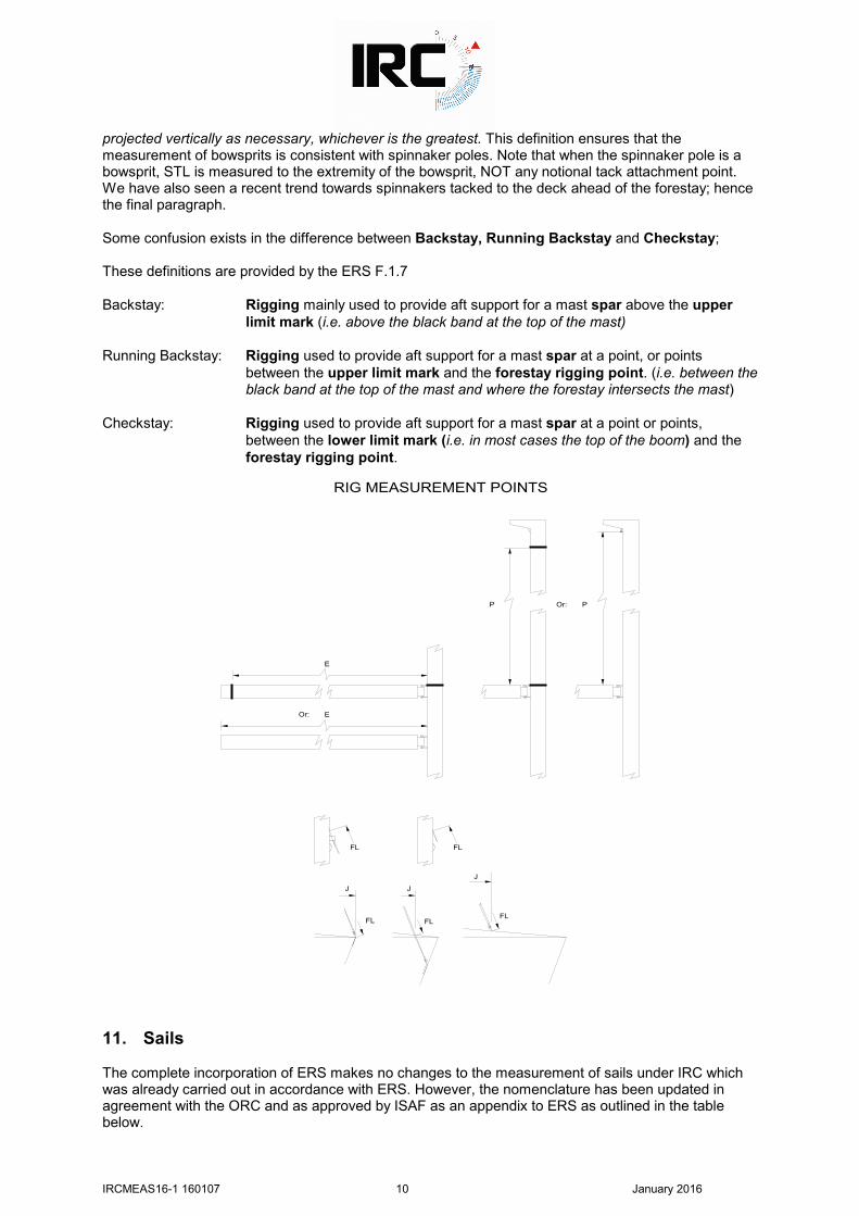
These changes clarify that a headsail may be hoisted and tacked from outside the foretriangle. There was a detail change to the definition of LP in 2012 relevant to the measurement of cutter rigs. In this definition, the previous wording to the foremost forestay was replaced by to the foremost headsail luff which may be set simultaneously while racing. J is therefore measured in exactly the same manner as for other common rating rules. Note that J is measured horizontally. A spirit level to project upwards from the forward measurement point to the height of the mast at deck level is nearly always necessary. FL can be a little more complex depending on the detail of the forestay attachment. What is required is the point where the centreline of the forestay intersects the front wall of the mast, or would if extended. The only exception to this is a masthead rig where the upper limit is the top surface of the mast. The attached diagrams show the various possibilities. Again someone will need to go up the mast. At the bottom of FL, the measurement point is as for J. The diagrams attached show all of the above. Measurers should be clear that we want the real forestay, not a thin cable that is declared as permanent, but which clearly achieves nothing when it comes to holding the rig up. P and FL may also be measured with the rig down. In both cases however, measurement will be to a reference mark on the mast/forestay for later correction to the actual lower limit of P/FL. With effect from 2013, the definition of E has been amended by the addition of: Fittings, local curvature, local cutaway and any increase in the fore/aft dimension of a sail track
and/or sail track support, shall be ignored. This closes a loophole applicable to large boats with in-boom mainsail furling but which could also have been exploited by smaller boats. STL is slightly different from ORCi/ORC Club. The definition says: The length of the longest spinnaker pole, whisker pole or bowsprit measured on or near the centre line of the boat from the forward face of the mast spar to the extremity of the spinnaker pole, whisker pole or bowsprit, or the horizontal length from the forward face of the mast spar at deck level to the spinnaker tack point on deck
IRCMEAS16-1 160107 10 January 2016
projected vertically as necessary, whichever is the greatest. This definition ensures that the measurement of bowsprits is consistent with spinnaker poles. Note that when the spinnaker pole is a bowsprit, STL is measured to the extremity of the bowsprit, NOT any notional tack attachment point. We have also seen a recent trend towards spinnakers tacked to the deck ahead of the forestay; hence the final paragraph. Some confusion exists in the difference between Backstay, Running Backstay and Checkstay; These definitions are provided by the ERS F.1.7 Backstay: Rigging mainly used to provide aft support for a mast spar above the upper
limit mark (i.e. above the black band at the top of the mast) Running Backstay: Rigging used to provide aft support for a mast spar at a point, or points
between the upper limit mark and the forestay rigging point. (i.e. between the black band at the top of the mast and where the forestay intersects the mast)
Checkstay: Rigging used to provide aft support for a mast spar at a point or points,
between the lower limit mark (i.e. in most cases the top of the boom) and the forestay rigging point.
E
EOr:
P POr:
FL FL
FL FLFL
J
J J
RIG MEASUREMENT POINTS
11. Sails The complete incorporation of ERS makes no changes to the measurement of sails under IRC which was already carried out in accordance with ERS. However, the nomenclature has been updated in agreement with the ORC and as approved by ISAF as an appendix to ERS as outlined in the table below.
IRCMEAS16-1 160107 11 January 2016
IRC Rules do not differentiate between spinnaker types. All spinnakers are measured in the same way, irrespective of shape. With effect from 2013, IRC Rule 21.1.5 (h) prohibits sails with detachable pieces. IRC sail measurement is very straightforward. Mainsails require measurement of widths, 5 measurements for headsails (with from 2013 Top Width replaced by Upper (7/8) Width), and 4 for spinnakers as follows: Further details and diagrams are provided in Appendix 3, 5, 6, 7 & 8. Previously Now Mainsails: Half Width MHW MHW Three Quarter Width MTW MTW Upper (seven eighth) Width MUW MUW Headsails: Luff length LL HLU Luff Perpendicular LP HLP Half Width HHW HHW Three-Quarter Width HTW HTW Upper (seven eighth) Width HUW HUW Spinnakers: Luff length SLU SLU Leech Length SLE SLE Foot Length SF SFL Mid Width SHW SHW For all measurements, light tension should be applied to the cloth, sufficient to remove wrinkles. Measurers should however be aware of the potential shortfall in luff length caused by not stretching the boltrope when measuring HLU, and if uncertain should err on the side of excessive tension. Measurers should also be aware that sailmakers on occasion (and particularly for smaller boats with hanks as opposed to luff grooves) sometimes fit pre-stretched headsail bolt ropes which when relaxed are significantly shorter than the luff length of the sail itself. In this context, light tension may be taken to mean firmly pulled by hand. IRC definitions define a spinnaker as Spinnaker: RRS 50.4 shall not apply. A spinnaker is defined as a sail set forward of the foremost
mast with half width (measured as a spinnaker) equal to or greater than 75% of foot length and without battens.
Thus, if a sail satisfies the definition of a spinnaker (ie half width is equal to or greater than 75% of foot), then that is what it is: a spinnaker. Any other sail is a headsail. ‘Code zeros’ are nearly always intended by the sailmaker to be spinnakers. Measurers should however beware. If however a sail has battens, defined in IRC as Any material added to the sail, as either a removable element, permanent stiffening, or other contrivance, the purpose of which is to support and/or stiffen the sail. then it is a headsail rather than a spinnaker, irrespective of what the dimensions are. With effect from 1st January 2013, measurement of headsail Top Width, HHB, is no longer required with the required dimensions now being HLU, HLP, HHW, HTW and HUW of the largest area headsail. In addition, the longest luff length (LLm) of any headsail carried is also required. In parallel the calculation of HSA, was amended to: HSA = 0.0625*HLU*(4*HLP + 6*HHW + 3*HTW + 2*HUW + 0.09) The IRC definition of HUW defines upper leech point as the point on the leech equidistant from the head point and the three-quarter leech point. This point is simply found by folding the head of the sail to the three-quarter leech point.

IRCMEAS16-1 160107 12 January 2016
Historically, HHW and HTW were never taken as less than 50% & 25% of HLP respectively for the purpose of the calculation. With effect from 2012, these minima have been removed. Measurers should therefore measure HHW and HTW for all headsails so that boats get the rating benefit of any general leech hollow. Measurers should however be aware that it is very common for the leech of a sail to be hollow between battens. Measurers should check all sails and bridge any hollows between battens found as described by ERS (see Appendix 3). The actual dimensions of the largest area headsail, (not just HSA) are needed. The IRC definitions of HLU, HLUmax and HLP now include: and which may be used while racing. This then formally covers the situation of a boat rated with a single roller furling headsail carrying other sails on board as permitted by Rule 21.8.4 without affecting her TCC. From 1st January 2013, there is a new IRC definition of Foot Offset: Foot Offset The maximum offset between the edge of a headsail foot and a straight line
between tack point and clew point. This has been added to close a loophole and is linked to IRC Rule 21.7.1: If foot offset is greater than 7.5% of HLP, then foot offset shall be declared and foot offset shall
be added to HLU in the calculation of HSA. It is considered unlikely that many, if any, sails will have Foot Offset in excess of 7.5% of HLP. Measurers are asked however to check and report any excessive values found. We have also seen a recent trend towards careful placement of headsail battens to minimise ‘hollows’ as defined by ERS. If in doubt, please refer to ERS and/or consult your local IRC Rule Authority. For spinnakers, what is required are the dimensions of the largest area sail calculated from: SPA = ((SLU + SLE)/2) * ((SFL + (4 * SHW))/5) * 0.83 While SPA is all that is required for rating the boat, measurers are asked to submit actual sail dimensions to minimise the likelihood of error. For mainsails, the only dimensions required are the three widths. Note that with effect from 2012, the historic minima for mainsail widths have been removed. Attention is drawn to the quick reference guides to sail measurement included as Appendices 5, 6 and 7 to this manual. IRC does not include any rules regarding sail reinforcement. The historic rules relating to sailcloth have now effectively disappeared. While IRC Rule, 21.4 refers to 'exotic materials' in sailcloth, the current exotic list is none. IRC Rule 21.8 gives a rating credit to boats rated for a single roller furling headsail. To be eligible, (with the exception of boats with LH greater than 30.5m and IRC DLR greater than 60) rated HLP must be greater than 1.3*J. The Rating Authority will pick up qualification in this regard. More importantly from a measurer's point of view is that, while other sails may be carried aboard, only storm jibs and, when declared, heavy weather jibs may be used while racing. The definitions of storm and heavy weather jibs are as defined by IRC definitions: Storm Jib A headsail of area not greater than 5% foretriangle height squared, luff length not
greater than 65% of foretriangle height, and not containing aromatic polyamides, carbon or similar fibres.
HWJ Heavy weather jib. A headsail of area not greater than 13.5% foretriangle height
squared, and without reef points.

IRCMEAS16-1 160107 13 January 2016
Note that a No.3 headsail is NOT a Heavy Weather Jib. In relevant cases, IRC certificates show the maximum permitted heavy weather jib area. Finally on the subject of sails, be aware that sail cloth can shrink/grow with time, use and sometimes moisture. The fact therefore that a sail has a measurement stamp on it does not guarantee that it measures. For Equipment Inspection at events, the only sure way is actually to measure the sail.
SAIL MEASUREMENT POINTS
LEECH LUFF LEECH LUFF
HEADSAIL
SPINNAKER
LEECH HEAD POINT
SPINNAKER
FOOT
HEADSAIL LEECH
FOOT
CLEW POINT
HEADSAIL
FOOT
LUFF
FOOT
LUFF SPINNAKER
HEADSAIL
FOOT
LUFF
TACK POINT
LEECH
LUFF
HEADSAIL
IRCMEAS16-1 160107 14 January 2016
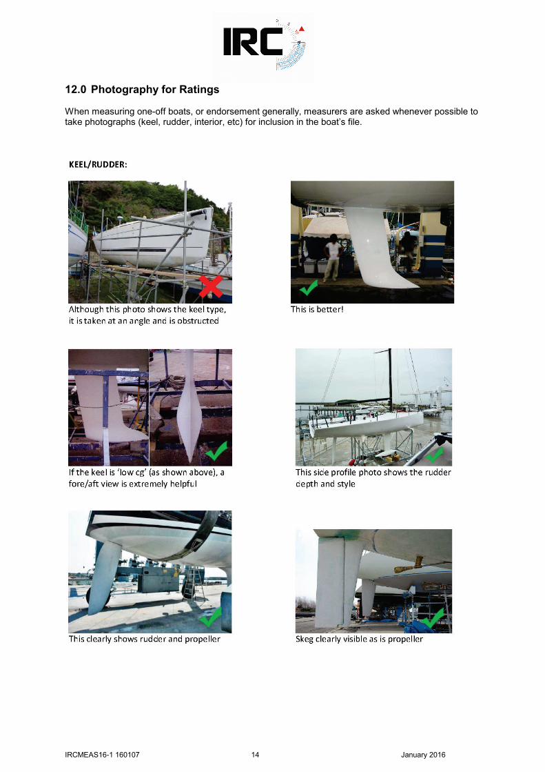
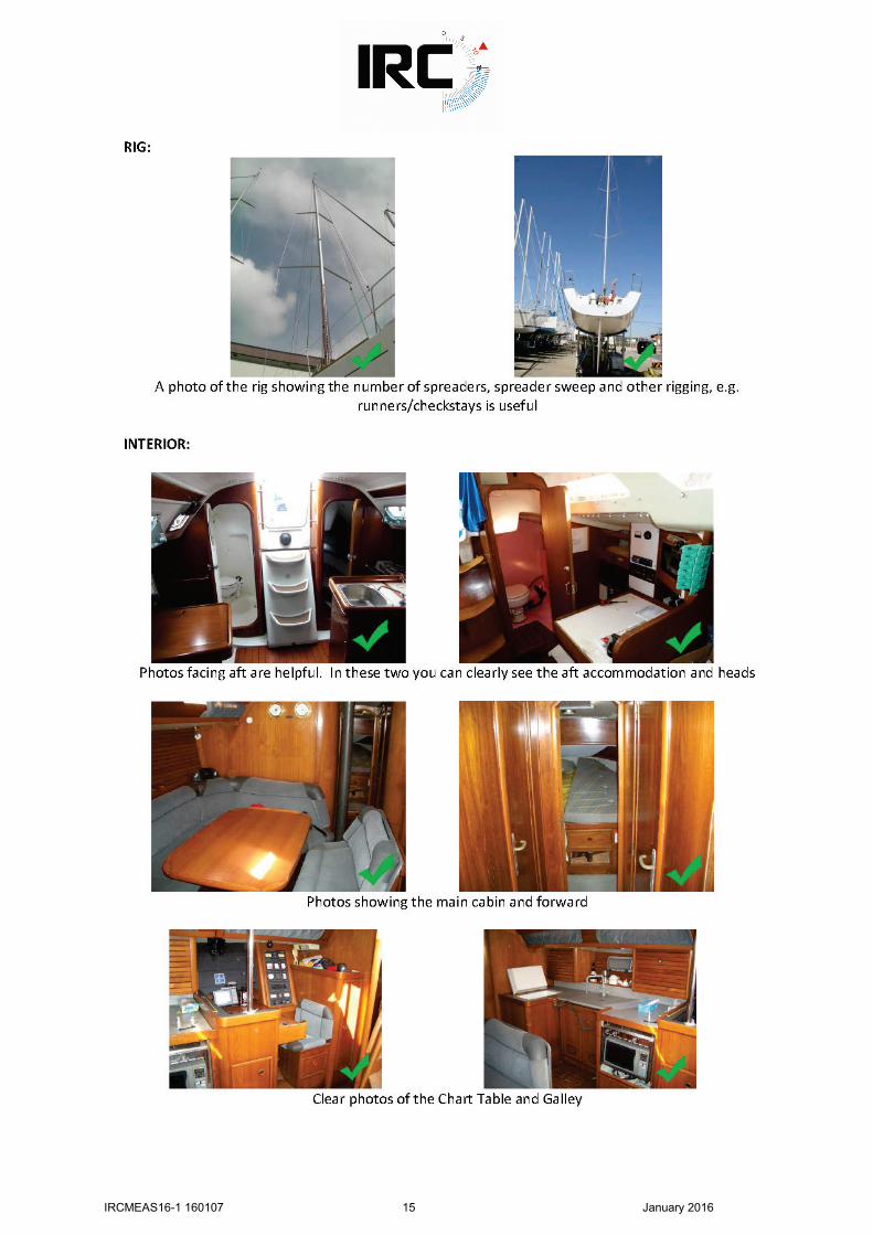
12.0 Photography for Ratings When measuring one-off boats, or endorsement generally, measurers are asked whenever possible to take photographs (keel, rudder, interior, etc) for inclusion in the boat’s file.
IRCMEAS16-1 160107 15 January 2016

IRCMEAS16-1 160107 16 January 2016
13.0 Other Issues Measurers should be aware of other IRC rules issues and are asked to report as much additional detail as possible for recording in a boat’s file. For instance: • Which version of the design? Mk I? MK II? Deep draft? Shallow draft? Etc. • Has furniture been removed from below and not reported in contravention of IRC rule 22.1? • Are removable cockpit boxes on board? • Are the correct number of spreaders/jumpers/runners/checkstays declared? • Is the mast aluminium or carbon? • Is the standing rigging wire, rod, or composite materials. Specifically, what is the forestay
material ? • Quantity (if any) of internal ballast. Has ballast been added or removed? • If originally an IOR rated boat, have the bumps and creases been faired out? • No. of spinnakers carried. • Does the boat use stored power? See IRC rule 15. • Does the boat have on board systems (other than conventional turnbuckles) to adjust the
forestay or the mast foot? If so, will the boat use these systems while racing? It is impossible to detail every point. Measurers are simply asked to check whatever detail is possible whenever possible. When measuring one-off boats, or endorsement generally, measurers are asked whenever possible to take photographs (keel, rudder, interior, etc) for inclusion in the boat’s file.
IRC Technical Committee January 2015

IRCMEAS16-1 160107 17 January 2016
APPENDIX 1
WEIGHING ON COMPRESSION LOAD CELLS It is recognised that weighing on compression load cells is becoming more and more attractive from a logistical and financial perspective. However, where possible it is always recommended that single point lift be the preferred option. Event organisers may require competitors to be weighed prior to an event. In such cases the recommendation is that such boats are weighed using the single point lift method. As with all measurement, accuracy and repeatability is paramount. There are 2 distinctly different methods of weighing on compression load cells: lowering the boat into a cradle supported on compression load cells and driving a travel lift onto pressure pads. Only the first method, lowering the boat into a cradle is acceptable for IRC weighing. Driving a travel lift onto pads and weighing the combined weight of the travel lift and boat, then deducting the weight of the travel lift is not acceptable but is currently under review. 1. There appear to be two types of compression load cells, one of which has the sensor at the top,
the other has the sensor at both ends. This latter type is not desirable because it requires a totally flat clean surface underneath as well as on top. If the latter type is to be used, each cell MUST be stood on a clean flat steel plate.
2. Flat level ground appears to be important. If not, the load may be unevenly shared between
corners (which in itself shouldn't matter) but may also vary during the weighing which will produce false readings.
3. There is also a possibility that non parallel ground/cradle surfaces may introduce errors into the
readings. 4. The bearing point on each cell must be cleanly in contact with the underside of the cradle.
Placing timber or other compressible material between the load cell and the cradle can result in the load being shared by the structure of the cell rather than only by the load sensitive part.
Additionally, it is important that the bearing point on each cell bears against a flat section of
cradle. Discontinuities in the cradle surface (created by welds, joints etc) must be avoided. 5 Wind can have an effect. Windage on the rig of a boat will change the distribution of load in the
cradle and hence the reading on each individual cell. The total net effect should be small, BUT when each cell has to be read individually, they really then need to be read at exactly the same moment.
The effects of this can be mitigated in the case of individual read-outs by laying out the read-outs
in such a way that it is possible to see all of them simultaneously. Cross variation can then be seen and noted.
6. If possible use equipment with the read out from each of the four cells electronically combined.
Read (if possible record) the read out at regular intervals so that a mean reading can be found.
In the case of a load cell read out combining electronically the signals from each cell, windage and uneven ground effects should be minimised. This does not make them any the less undesirable.
7. As ever, dunnage and packing used when the boat is in the cradle must be replaced on the
cradle for tare purposes. 8. For practical reasons, when the boats is lowered into a cradle the travel lift straps will generally
remain around the boat during the weighing. Obviously, care must be taken to ensure that they are slack.

IRCMEAS16-1 160107 18 January 2016
9. Accuracy. Given that 3 or 4 cells are used as opposed to 1 for a single point lift, the potential for inaccuracy is increased. Cells of the highest possible accuracy, rated as appropriately as possible for the gross weight become of greater importance.
10. Range. While for maximum accuracy, we want cells of combined total capacity as close as
possible to the gross weight, care needs to be taken because placing the boat in the cradle may result in a very uneven load distribution. This should be taken account of in sizing the cells.

IRCMEAS16-1 160107 19 January 2016
APPENDIX 2
OVERHANGS & WEIGHING OF SUPERYACHTS It is recognised that for very large boats, with Hull Length of 30.5m and greater, it is generally impractical to bring the boat into measurement condition, and not possible to weigh the boat by single point lifting. It is also extremely difficult and costly to weigh the boat on pressure pads, as this may require a dry dock and extremely substantial custom built cradle. As such the following alternative is permitted with prior approval of the Rating Authority for these very large boats. It may also be used for smaller but very heavy boats with the prior approval of the Rating Authority. As with all measurement, accuracy and repeatability is paramount. This method takes time, so accept that and don’t rush it. It is imperative that the condition of the boat is recorded accurately as outlined below: 1. Ensure the Rule Authority is aware of the method being used, and that the Rating Authority has
sanctioned it. 2. Ensure that a set of hull lines are provided by either the designer or from an ORC IMS
measurement or similar, in a format that can be used to calculate the displacement and trim changes in the appropriate software. Discuss this with the designer and Rule Authority first.
3. Ensure that the boat captain is aware of the process and the time required to complete the work.
Also make the boat captain aware that the closer to empty the boat is, the less chance for error there is. So ask them to empty the boat as far as reasonably possible. If sails, or other heavy items which cannot be easily weighed are to remain on board, ask the boat captain to provide weights for these items. For very large sails the sail maker will have a record of the delivery weights at least, and will probably have a record of the fully dressed sail weight. Remember to include battens where necessary. Ask that any bow anchor be dropped to the seabed if possible with a lanyard left attached only for recovery, ensuring that there is no weight on the line.
4. In an ordered manner record the fore and aft location as well as the weight of everything that
should not be included in measurement condition. It is best to start at the bow and work aft, first above decks and then below decks, or vice versa, provided no location is overlooked. Fore and aft location can be recorded relative to the mast for simplicity. Multiple items, such as drinking water bottles can be counted and multiplied by the volume. Tankage can be recorded from the gauges, but remember to also record the location of each tank. It is best to compile this record on a spreadsheet so that the mean longitudinal location of the combined weigh can be calculated relative to the mast.
5. Once all is recorded the mooring lines should be eased as much as possible and the
measurements y and h are recorded at the bow and stern as accurately as possible. For this the conditions have to be at least as good as a normal overhang measurement.
6. Provide the full information to the designer and Rule Authority so that the measured
displacement and overhangs can be calculated. From this the recorded weight can then be deducted from the calculated location and the weight and overhangs adjusted and recorded for use in the IRC calculation.
7. Record as much as possible with a camera, with the boat captain’s permission. Also recognise
that the crew may live on the boat full time. Respect their privacy in areas of the boat where their personal belongings are kept, as well as the privacy of the owner.
8. This is a costly and time consuming process. As such ensure as much as possible is prepared
beforehand, and ensure that the Rule Authority is fully aware of what you are doing. The Rating Authority will be at hand to answer any questions whenever possible. Do not be afraid to ask.

IRCMEAS16-1 160107 20 January 2016
APPENDIX 3
ERS H.5.2, Hollows in Sail Edges H.5.2 Hollows in Sail Leeches Where there is a sail leech hollow and a measurement point falls in the hollow: between adjacent batten pockets between the aft head point and the adjacent batten pocket between the clew point and the adjacent batten pocket at an attachment the sail shall be flattened out in the area of the sail edge, the sail edge hollow shall be bridged by a straight line and the shortest distance from the measurement point to the straight line shall be measured. This distance shall be added to the measurement being taken.

IRCMEAS16-1 160107 21 January 2016
APPENDIX 4
IRC Endorsement
Process, Measurement, and Data Standards 1. Preamble An ‘endorsed’ IRC certificate is one for which the data on the certificate has been audited and if necessary verified by measurement (official measurers) or other methods. The 2005 IRC Congress agreed that a set of common standards for the IRC Rating Authority and Rule Authorities to apply when endorsing a boat’s IRC certificate should be developed and published. Generally, IRC is a self-measurement system. There is thus no general requirement for an owner to have his boat officially measured or weighed unless either he chooses to do so, or his Rule Authority (ie his local IRC body) and/or an Organising Authority for a race requires official measurement, generally resulting in an endorsed IRC certificate. As a part of this, in future, the nomenclature on an endorsed IRC certificate issued by either the RORC Rating Office or the UNCL Centre de Calcul will be:
ENDORSED meaning that the data has been audited by a Rule Authority with any measurement by a measurer recognised by the Rule Authority.
Within the guidelines below Rule Authorities are given some options for sources of data. This recognises that circumstances vary from country to country, that some owners are prepared to expend more time and effort than others, and that for instance weighing a large boat may be impractical. The options offered cater for these while at the same time not generally compromising the validity of a boat’s data and hence her endorsed certificate. It is a fundamental prerequisite of this that responsibility for appointment and training of measurers and quality of measurement data generally lies with each Rule Authority. Attention is drawn to the IRC Measurement Manual available from the IRC website, www.ircrating.org. Additional material to aid Rule Authorities and measurers is also available direct from the Rating Authority. 2. Process An owner wishing to have his certificate endorsed first contacts his local Rule Authority. The Rule Authority carries responsibility for auditing the boat’s data file and for defining what, if any, data is to be verified. In doing this, the data and measurement standards below shall be applied. If these standards are not applied, then the Rating Authority must be advised and an endorsed certificate will not be issued On return of the data from the measurer, or other defined source, the Rule Authority will review the data and confirm that it is satisfied that an endorsed certificate can be issued. The data is then forwarded to the Rating Authority accompanied by a request to issue an endorsed certificate. Only then will the Rating Authority issue an Endorsed certificate. The Rating Authority reserves the right at its absolute discretion to refuse to issue an endorsed certificate if it is not satisfied in any respect with the data submitted by a boat through her Rule Authority.
IRCMEAS16-1 160107 22 January 2016
3. Measuring Equipment While measurement methods are generally beyond the scope of this, the following shall apply. 3.1 Load Cells Load cells for single point lift weighing shall have a quoted accuracy of +/-0.2% of maximum capacity or equivalent and discrimination of not less than 10 kg. ie, a 10 tonne load cell should have a quoted accuracy of +/- 20 kg, and a 20 tonne cell, +/- 40 kg. Load cells shall be calibrated at least once per year. A load cell should not be used to weigh a boat weighing less than 15% of the maximum capacity of the load cell, ie 1500 kg for a 10 tonne cell. Rule Authorities may waive this requirement on an individual case basis. Compression load cells should generally follow the above standards. It is however recognised and noted that the ultimate accuracy of weighing on compression load cells is a function of the combined accuracy of all the cells rather than the accuracy of each individual cell and also of the methodology adopted. Rule Authorities are therefore advised to exercise care in approving compression load cells. 3.2 Linear Measurements Tape measures and measuring rules built to CE category 2 or equivalent standards are acceptable. Tape measures should be steel. Fabric tapes are not generally acceptable.
IRCMEAS16-1 160107 23 January 2016
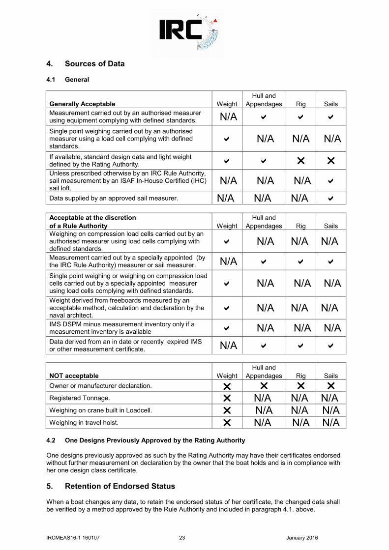
4. Sources of Data 4.1 General Hull and Generally Acceptable Weight Appendages Rig Sails Measurement carried out by an authorised measurer using equipment complying with defined standards. N/A
Single point weighing carried out by an authorised measurer using a load cell complying with defined standards.
N/A N/A N/A If available, standard design data and light weight defined by the Rating Authority. Unless prescribed otherwise by an IRC Rule Authority, sail measurement by an ISAF In-House Certified (IHC) sail loft.
N/A N/A N/A
Data supplied by an approved sail measurer. N/A N/A N/A Acceptable at the discretion Hull and of a Rule Authority Weight Appendages Rig Sails Weighing on compression load cells carried out by an authorised measurer using load cells complying with defined standards.
N/A N/A N/A Measurement carried out by a specially appointed (by the IRC Rule Authority) measurer or sail measurer. N/A
Single point weighing or weighing on compression load cells carried out by a specially appointed measurer using load cells complying with defined standards.
N/A N/A N/A Weight derived from freeboards measured by an acceptable method, calculation and declaration by the naval architect.
N/A N/A N/A IMS DSPM minus measurement inventory only if a measurement inventory is available N/A N/A N/A Data derived from an in date or recently expired IMS or other measurement certificate. N/A Hull and NOT acceptable Weight Appendages Rig Sails Owner or manufacturer declaration. Registered Tonnage. N/A N/A N/A Weighing on crane built in Loadcell. N/A N/A N/A Weighing in travel hoist. N/A N/A N/A
4.2 One Designs Previously Approved by the Rating Authority One designs previously approved as such by the Rating Authority may have their certificates endorsed without further measurement on declaration by the owner that the boat holds and is in compliance with her one design class certificate. 5. Retention of Endorsed Status When a boat changes any data, to retain the endorsed status of her certificate, the changed data shall be verified by a method approved by the Rule Authority and included in paragraph 4.1. above.

IRCMEAS16-1 160107 24 January 2016
APPENDIX 5
Mainsail Measurement What is being measured? Half width, three quarter width and upper width.
What are these? The distances from the half, three quarter, and upper leech points to
the luff. In practice: 1. Lay the sail out flat on a suitable floor. 2 Establish head point and clew point as shown by the diagram. 3. Fold the head point to the clew point.
Mark the fold in the leech. That is half leech point
4. Fold the head point to the half leech point. Mark the fold. That is three quarter leech point. 5. Fold the head point to the three quarter leech point. Mark the fold. That is upper leech point. 6. Measure from each leech point to the nearest point on the luff. These distances are the
mainsail widths. 7. Check for sail leech hollows 8. Add any hollow (A) to each measured
Width (B) to get the final widths. References: Equipment Rules of Sailing. http://www.sailing.org/documents/isaf-equipment-rules.php. G.4.1 and G.4.2 define clew point and head point. G.5.2 and G.5.3 define Half Leech Point and three quarter leech point. IRC definitions define upper width of the mainsail as: MUW The upper width of the mainsail, the upper leech point being the point on the leech
equidistant from the three-quarter leech point and the head point.
G.7.5, G.7.6, and G.7.7 define half width, three quarter width and upper width. G.2.4 and H.5.2 address Sail leech hollows.
Head point Clew point Sail sail
Hollow Batten pocket Measurement point B B Hollow Batten pocket “A” to be added to measurement “B”
A

IRCMEAS16-1 160107 25 January 2016
APPENDIX 6
Headsail Measurement What is being measured? Luff length, luff perpendicular (LP), half width, three quarter width
and upper width, headsail foot offset.
What are these? The length of the luff, the distance between the clew point and the luff, and the distances from the half, three quarter and upper leech points to the luff.
In practice: 1. Lay the sail out flat on a suitable floor. 2 Establish head point, tack point
and clew point as shown by the diagram. 3. Straighten the luff and pulling firmly
measure the luff length between the head point and the tack point.
4. Measure LP from the clew point
to the nearest point on the luff. 5. Fold the head point to the clew point.
Mark the fold. That is half leech point. 6. Fold the head point to the half leech point.
Mark the fold. That is three quarter leech point.
7. Fold the head point to the three quarter leech point. Mark the fold. That is upper leech point.
8. Measure from each leech point to the nearest point
on the luff. This will give the half, three quarter and upper widths.
9. Check for sail leech hollows. 10. Add any hollow (A) to each measured
width (B) to get the final widths. References: Equipment Rules of Sailing. http://www.sailing.org/documents/isaf-equipment-rules.php. G.4.1, G.4.2 and G.4.3 define clew point, head point, and tack point. G.5.2, G.5.3 and G.5.4 define half leech point, three quarter leech point and upper leech point. G.7.3 defines luff length. G.7.5, G.7.6 and G.7.7 define half width, three quarter width and upper width. G.7.11 defines luff perpendicular. G.2.4 and H.5.2 address sail leech hollows.
Head point sail sail
Sail Tack Point sail Clew Point
Hollow Batten pocket Measurement Point B B Hollow “A” to be added to measurement “B” Batten pocket
A

IRCMEAS16-1 160107 26 January 2016
APPENDIX 7
Headsail Foot Offset
To prevent the practice of reducing headsail dimensions and the corresponding area calculations by exaggerating the curve of the foot artificially raising the tack and clew, Foot Offset is controlled. This is referenced in IRC Rule 21.7.1 If foot offset is greater than 7.5% of LP, then foot offset shall be declared and foot offset shall be added
to LL in the calculation of HSA. What is Foot Offset?: - It is the maximum offset distance between the edge of a headsail foot and a straight line between tack point and clew point How is it Measured: 1 – Lay out the sail flake as necessary so that the foot area is flat on the
floor. 2 – Determine the tack and clew points and measure LP. 3 – Run a string line from tack to clew.
4 – Visually determine the position of the maximum distance from string line to headsail foot, measure perpendicular to the string line from headsail foot to string line at this point. 5 – Repeat the measurement from string line to headsail foot in numerous
locations to ensure that the maximum dimension has been determined. 6 – Foot Offset % is calculated by 100 * Foot Offset Measrement / LP 7 – If the foot offset is greater than 7.5% the dimension should be submitted
with the headsail data on the measurement input form.
Clew Point LP Foot Offset Tack Point

IRCMEAS16-1 160107 27 January 2016
APPENDIX 8
Spinnaker Measurement What is being measured? Luff length, leech length, foot length and half width.
What are these? The lengths of the luff, leech and foot and the distance from the half luff
point to the half leech point. In practice: 1. Lay the sail out flat on a suitable floor. 2 Establish head point, tack point
and clew point as shown by the diagram. Note that for a symmetric spinnaker, luff/leech and
tack point/clew point are interchangeable. 3. Straighten the luff and measure the luff length
between the head point and the tack point. 4. Straighten the leech and measure the leech length
between the head point and the clew point. 5. Straighten the foot and measure the foot length
between the tack point and the clew point. 6. Fold the head point to the tack point.
Mark the fold. That is half luff point. 7. Fold the head point to the clew point.
Mark the fold. That is half leech point.
8. Measure from the half luff point to the half leech point. This will give you half width. References: Equipment Rules of Sailing. http://www.sailing.org/documents/isaf-equipment-rules.php. G.4.1, G.4.2 and G.4.3 define clew point, head point, and tack point. G.5.2 defines half leech point. G.5.7defines half luff point. G.7.1, G.7.2 and G.7.3 define foot length, leech length and luff length. G.7.5 (b) defines half width.
Head point
sail
Tack point and
clew point Sail
IRCMEAS16-1 160107 28 January 2016
APPENDIX 9
Bulb Weight Measurement
For several years now we have required bulb weight to be provided for keel types 10, 11 and 12. There are several methods which may be used to establish this, with varying levels of accuracy and reliability. In general we will not require this to be measured and if you do plan to measure it please contact the Rule Authority to confirm that it is necessary and which method is to be used as a preference. We will also base the rating calculation on the most accurately understood data that we have. However, if needed, the methods used are detailed below: 1. Weigh the bulb. This is the ultimate check for us. The bulb needs to be weighed separately from the keel fin, normally at a stage of manufacture and normally this is only possible when a new keel is being assembled. This needs to be done in exactly the same way as boat weight, using a single point lift with an appropriately calibrated and tested load cell. Allowance may need to be made for lifting eyes and corrector weight pockets, along with any additional lead that may be fitted into the fin to bulb recess. This is generally only an option for top level programs of new builds, and is not something we can rely upon being an option in most cases. 2. Designer/builder declaration. Most boat builders these days will be purchasing the keel from a sub-contractor. In these cases it is common practice for the principle builder to require proof of weight in the purchase agreement so that they can confirm they have got what they have asked for and that it coincides with the designer’s specification. Similarly, the designer will have a target weight for the bulb even if they have not required proof of weight. Again, whilst this information is likely to be somewhere for most boats with these keel types, records of it may be difficult to obtain for older builds and where modifications have been made. We also never really know whether an owner has filled or emptied pockets, or altered the bulb. And often the original designer and builder may not be aware of changes made. It is however a good reference point and in the vast majority of cases will represent the actual bulb weight well. 3. Volume measurement. This can be completed in several ways. I have tried to list these in order of simplicity of measurement. But each situation will present different issues and a combination of methods will hopefully validate each other. a) Immersed volume
When the boat is being weighed and is over the water, ask the crane driver to hold the boat with the bulb only immersed. Record the boat weight in this position and when completely clear of the water. The difference in weight will give you the immersed volume of the bulb. Provide this information with the measurement data. Quite simply, if the difference in weight is 1000kgs and the weighing is done in saltwater then the water density will be approximately 1025kgs/m3. As such the corrected volume would be 1025 litres. The density of pure lead is 11340kgs/m3. However, including the normal 1.5% antimony and other naturally occurring impurities it is unlikely that the density will be higher than 11000kgs/m3. As such the calculated bulb weight for this volume would be 11000kgs.
b) Measurement of volume There are several methods that can be used, from the more complex approach of a full laser scan or photogrammetry (photo below) to simply measuring length and circumference at selected points along the length. From this a combination of cross-sectional area and Simpsons rule can be used to calculate the volume of the bulb.

IRCMEAS16-1 160107 29 January 2016
The inaccuracies in these method are:
Density of water estimated. This can be overcome by using a hydrometer and measuring the density. Does not apply to method b).
Density of the bulb. This needs to be estimated. However, deviation is likely to be small.
Unaccounted pockets. There are likely to be voids in the bulb for attachments and possible adjustment pockets. If detail is known of these then they can be accounted for.
Internal structure. Some keels may have internal steel cages. These will reduce the density slightly, but it is best to ignore these unless details are available. But if details are available then we will likely also have full bulb weight details.
Defining the top of the bulb. With a sharp intersection of the bulb to fin joint this is easy to establish. But with a large radius then some assessment is needed. Best to stop the crane at the bottom of the radius, as the joint is likely to be primarily filler and not made of lead.
For clarity, we consider the definition of the bulb in the following way:
IRC Bulb Weight refers to the Bulb as defined by the ISAF Equipment Rules of Sailing. This document is
provided as clarification that all under-fin spacers and in-fills shall be included in the total Bulb Weight.
The ERS defines Bulb as
E.1.2(e) A hull appendage containing ballast at the bottom of another hull appendage primarily used to
affect stability.
Ballast is defined as
C.6.3(e) Weight installed to influence the stability, flotation or total weight of the boat.
E.1.1 defines Hull Appendage as
Hull Appendage Any item of equipment – including the items listed in E.1.2– which is:
• wholly or partly below the sheerline or its extension when fixed or when fully exposed if retractable,
• attached to the hull shell or another hull appendage, and used to affect: stability, leeway, steerage,
directional stability, motion damping, trim, displaced volume.

IRCMEAS16-1 160107 30 January 2016
And clarifies that:
Any of the following shall be included in the hull appendage:
• corrector weights,
• integral ballast, and
• associated fittings.
Therefore, all under-fin spacers and in-fills shall be included in the total Bulb Weight.