2016 Engineering Symposium – Rochester April 26, 2016 · 2016 Engineering Symposium – Rochester...
40
Page 1 NEC Article 695-Fire Pumps 1 Installation Requirements for Electrically Driven Fire Pumps 2016 Engineering Symposium – Rochester April 26, 2016 Motor Circuit Elements – NEC Article 430 • Short‐Circuit Ground‐Fault Protection • Overload Protection • Circuit Conductors • Controller • Disconnecting Means 2
Transcript of 2016 Engineering Symposium – Rochester April 26, 2016 · 2016 Engineering Symposium – Rochester...

Page 1
NEC Article 695-Fire Pumps
1
Installation Requirements for Electrically Driven Fire Pumps
2016 Engineering Symposium – RochesterApril 26, 2016
Motor Circuit Elements – NEC Article 430
• Short‐Circuit Ground‐Fault Protection
• Overload Protection
• Circuit Conductors
• Controller
• Disconnecting Means
2
Page 2
NEC Article 695-Fire Pumps
3
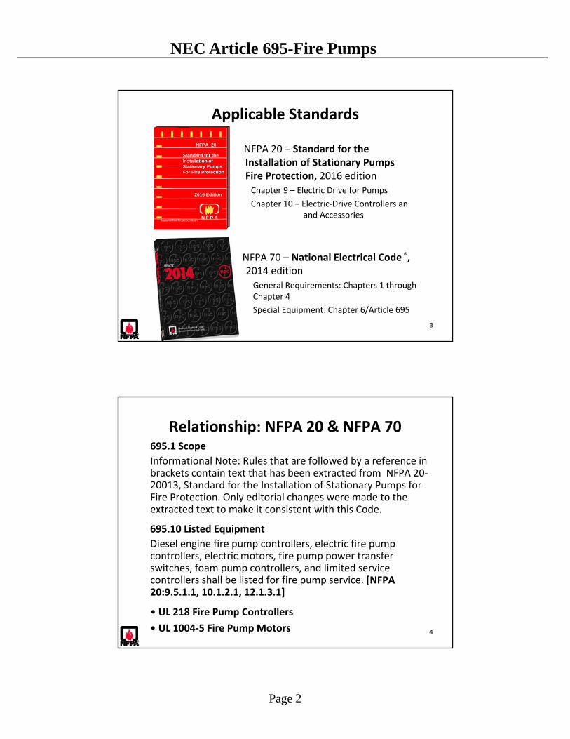
Applicable Standards
NFPA 20 – Standard for the Ins Installation of Stationary Pumps for Fire Protection, 2016 edition
Chapter 9 – Electric Drive for Pumps
Chapter 10 – Electric‐Drive Controllers an and Accessories
NFPA 70 – National Electrical Code ®, 2014 editionGeneral Requirements: Chapters 1 through Chapter 4
Special Equipment: Chapter 6/Article 695
NFPA 20
Standard for theInstallation ofStationary Pumps For Fire Protection
2016 Edition
National Fire Protection Assn.N F P A
4
Relationship: NFPA 20 & NFPA 70695.1 Scope
Informational Note: Rules that are followed by a reference in brackets contain text that has been extracted from NFPA 20‐20013, Standard for the Installation of Stationary Pumps for Fire Protection. Only editorial changes were made to the extracted text to make it consistent with this Code.
695.10 Listed Equipment
Diesel engine fire pump controllers, electric fire pump controllers, electric motors, fire pump power transfer switches, foam pump controllers, and limited service controllers shall be listed for fire pump service. [NFPA 20:9.5.1.1, 10.1.2.1, 12.1.3.1]
• UL 218 Fire Pump Controllers
• UL 1004‐5 Fire Pump Motors
Page 3
NEC Article 695-Fire Pumps
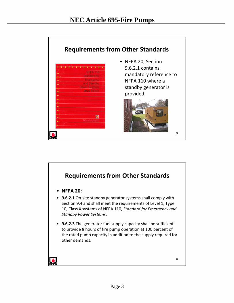
Requirements from Other Standards
• NFPA 20, Section 9.6.2.1 contains mandatory reference to NFPA 110 where a standby generator is provided.
5
2016
Requirements from Other Standards
• NFPA 20:
• 9.6.2.1 On‐site standby generator systems shall comply with Section 9.4 and shall meet the requirements of Level 1, Type 10, Class X systems of NFPA 110, Standard for Emergency and Standby Power Systems.
• 9.6.2.3 The generator fuel supply capacity shall be sufficient to provide 8 hours of fire pump operation at 100 percent of the rated pump capacity in addition to the supply required for other demands.
6
Page 4
NEC Article 695-Fire Pumps
Requirements from Other Standards
• NFPA 110:
• 7.2 Location.
• 7.2.1 Indoor EPS Installations. The EPS shall be installed in a separate room for Level 1 installations.
• 7.2.1.1 The EPS room shall be separated from the rest of the building by construction with a 2‐hour fire resistance rating.
• 7.2.1.2 EPSS equipment shall be permitted to be installed in the EPS room.
• 7.2.1.3 No other equipment, including architectural appurtenances, except those that serve this space, shall be permitted in the EPS room.
7
8
Other Applicable Standards
• UL–218 Fire Pump Controllers
• UL 1004‐5 Fire Pump Motors
• UL Fire Resistance Directory
Page 5
NEC Article 695-Fire Pumps
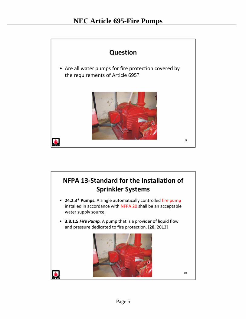
Question
• Are all water pumps for fire protection covered by the requirements of Article 695?
9
NFPA 13‐Standard for the Installation of Sprinkler Systems
• 24.2.3* Pumps. A single automatically controlled fire pump installed in accordance with NFPA 20 shall be an acceptable water supply source.
• 3.8.1.5 Fire Pump. A pump that is a provider of liquid flow and pressure dedicated to fire protection. [20, 2013]
10
Page 6
NEC Article 695-Fire Pumps
NFPA 13R‐Installation of Sprinkler Systems in Low‐Rise Residential Occupancies
• Low‐Rise Residential Occupancy– 60 ft. or less in height above grade plane
– Not more than 4 stories
– Apartment buildings; hotels, motels and dormitories; lodging and rooming houses; board and care facilities
• Standard based on the concept that the sprinkler system is designed to protect against a fire originating at a single location
11
NFPA 13R – Installation of Sprinkler Systems in Low‐Rise Residential Occupancies
• 9.3* Source. The water supply source shall be one of the following:– (1)*A connection to a reliable waterworks system with or without a
pump, as required
– (2) An elevated tank
– (3) A pressure tank installed in accordance with NFPA 13 and NFPA 22
– (4)*A stored water source with an automatically operated fire pump
• 9.4 Fire Pump. Where a fire pump is installed, the fire pump shall be installed in accordance with NFPA 20.
12

Page 7
NEC Article 695-Fire Pumps
NFPA 13D – Standard for the Installation ofSprinkler Systems in One‐ and Two‐Family
Dwellings and Manufactured Homes
• 5.1.3 Tanks, expansion tanks, pumps, hangers, waterflowdetection devices, and waterflow valves shall not be required to be listed.
• 6.2* Water Supply Sources. The following water supply sources shall be considered to be acceptable by this standard:
(1) A connection to a reliable waterworks system with or without an automatically operated pump
• 3.3.8 Pump. A mechanical device that transfers or raises, or transfers and raises, the pressure of a fluid (water).
13
NFPA 13D – Standard for the Installation ofSprinkler Systems in One‐ and Two‐Family
Dwellings and Manufactured Homes
• Not required to be a listed fire pump
• Separate pump for fire protection required to operate @ 240 volts
• Type of controller is not specified
• Follow general requirements in Chapters 1 through 4 of NEC for motor/motor operated appliance installations
14
Page 8
NEC Article 695-Fire Pumps
Question
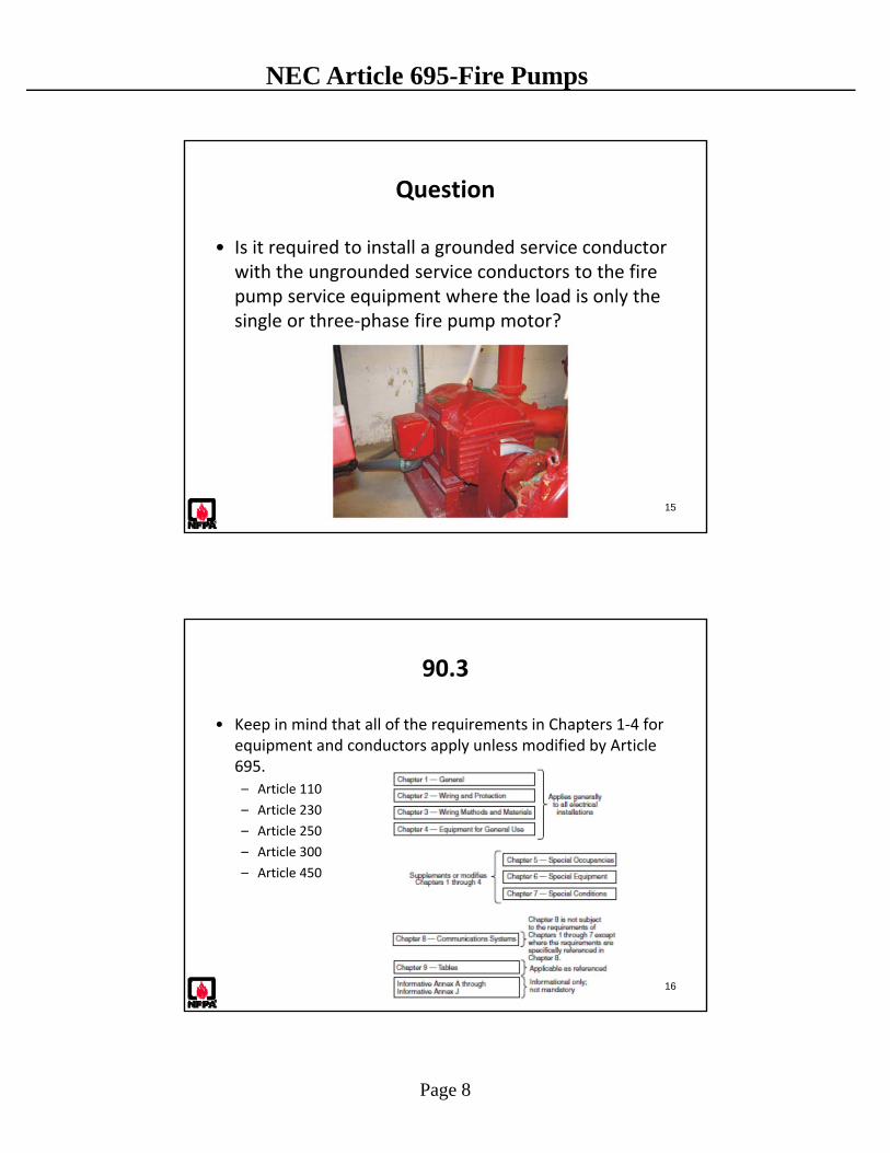
• Is it required to install a grounded service conductor with the ungrounded service conductors to the fire pump service equipment where the load is only the single or three‐phase fire pump motor?
15
90.3
• Keep in mind that all of the requirements in Chapters 1‐4 for equipment and conductors apply unless modified by Article 695.– Article 110
– Article 230
– Article 250
– Article 300
– Article 450
16
Page 9
NEC Article 695-Fire Pumps
250.24 (C)
• (C) Grounded Conductor Brought to Service Equipment. Where an ac system operating at 1000 volts or less is grounded at any point, the grounded conductor(s) shall be routed with the ungrounded conductors t o each service disconnecting means and shall be connected to each disconnecting means grounded conductor(s) terminal or bus. A main bonding jumper shall connect the grounded conductor(s) to each service disconnecting means enclosure. The grounded conductor(s) shall be installed in accordance with 250.24(C)(1) through (C)(4).
17
Question
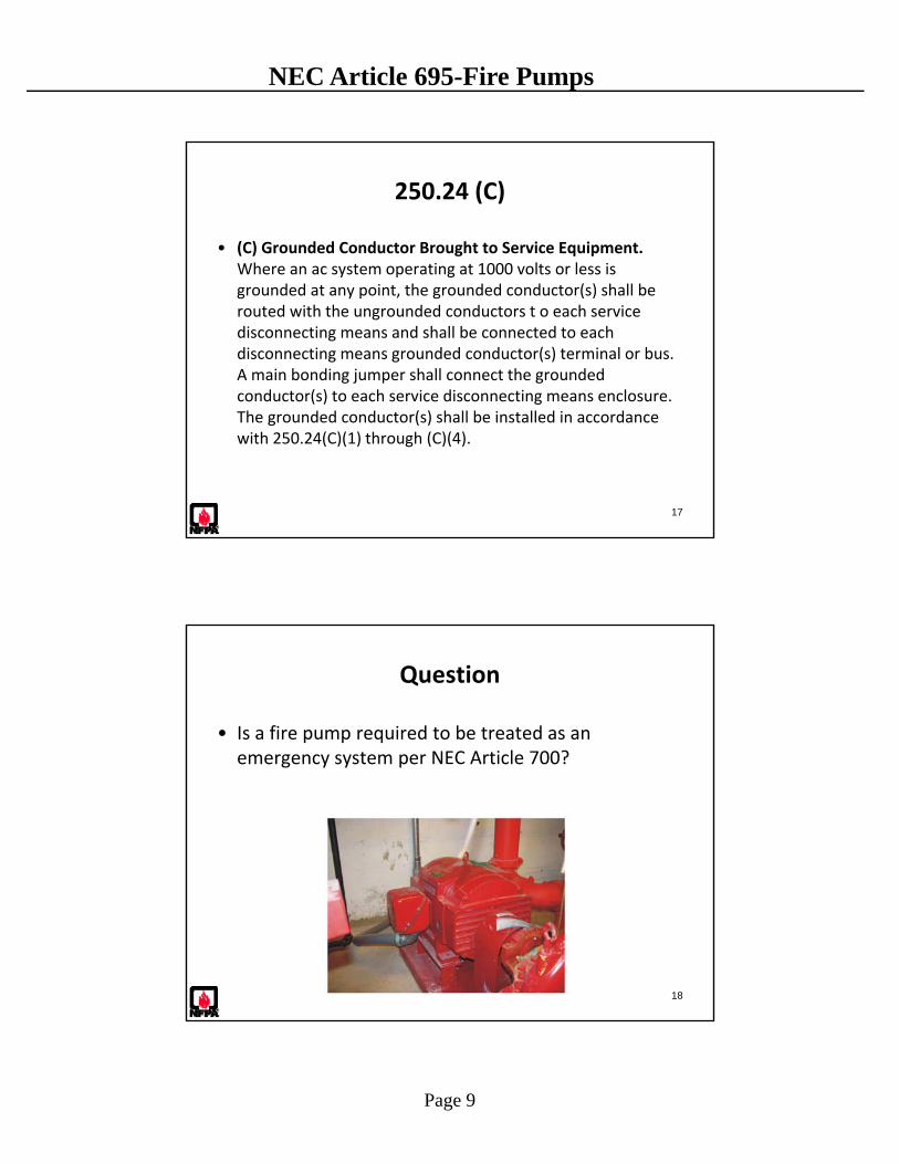
• Is a fire pump required to be treated as an emergency system per NEC Article 700?
18
Page 10
NEC Article 695-Fire Pumps
19
695.1 – Scope(A) Covered:
(1) Electric power sources and interconnecting circuits (2) Switching and control equipment dedicated to fire pump
drivers
(B) Not Covered:(1) The performance, maintenance, and acceptance testing
of the fire pump system, and the internal wiring of the components of the system
(2) Pressure maintenance (jockey or makeup) pumps (not covered in Article 695, but motors in general are covered in Article 430
(3) Transfer equipment upstream of the fire pump transferswitch(es)
Informational Note: See NFPA 20‐2013, Standard for the Installation of Stationary Pumps for Fire Protection, for further information.
700.1 – Scope
The provisions of this article apply to the electrical safety of the installation, operation, and maintenance of emergency systems consisting of circuits and equipment intended to supply, distribute, and control electricity for illumination, power, or both, to required facilities when the normal electrical supply or system is interrupted.
20
Page 11
NEC Article 695-Fire Pumps
700.2 – Definition
Emergency Systems. Those systems legally required and classed as emergency by municipal, state, federal, or other codes, or by any governmental agency having jurisdiction.
Informational Note to 700.2: …Emergency systems may also provide power for such functions as ventilation where essential to maintain life, fire detection and alarm systems, elevators, fire pumps, public safety communications systems, industrial processes where current interruption would produce serious life safety or health hazards, and similar functions.
21
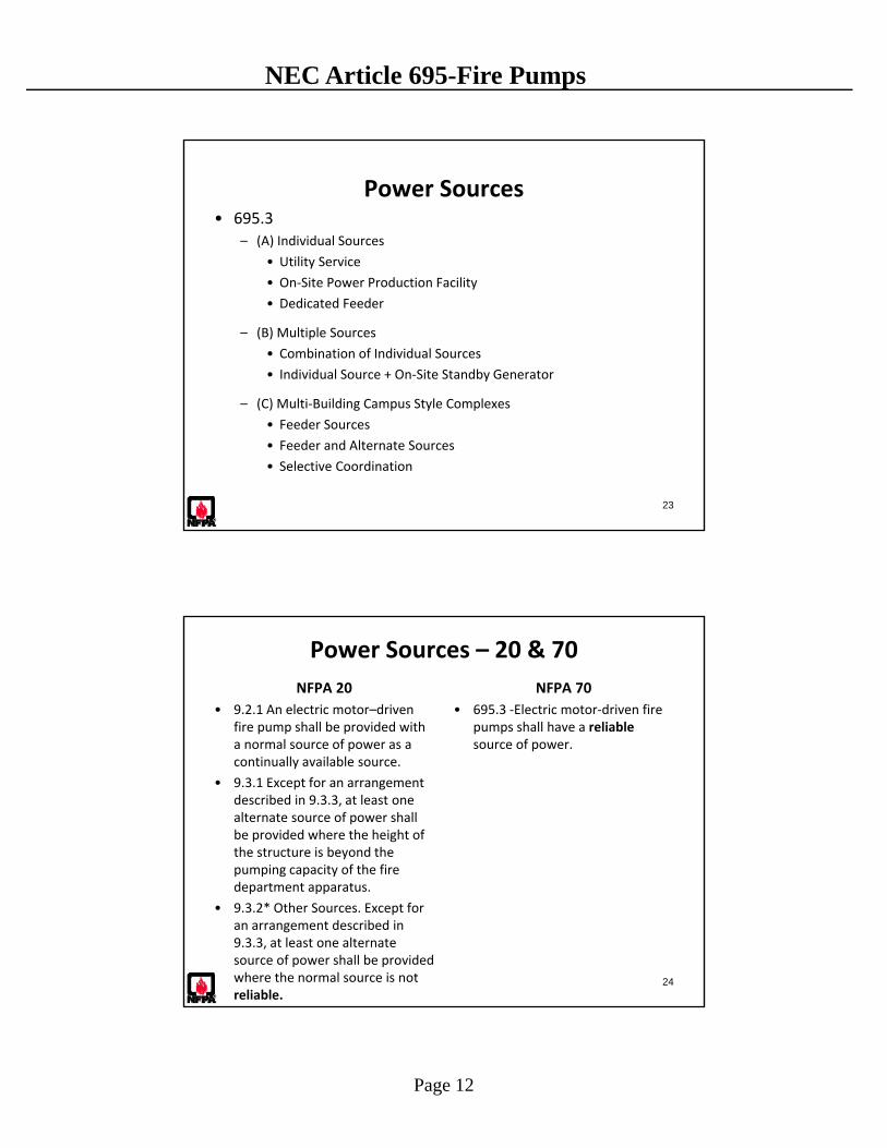
Question
• Can a fire pump be supplied by a single power source?
22
Page 12
NEC Article 695-Fire Pumps
Power Sources• 695.3
– (A) Individual Sources
• Utility Service
• On‐Site Power Production Facility
• Dedicated Feeder
– (B) Multiple Sources
• Combination of Individual Sources
• Individual Source + On‐Site Standby Generator
– (C) Multi‐Building Campus Style Complexes
• Feeder Sources
• Feeder and Alternate Sources
• Selective Coordination
23
24
Power Sources – 20 & 70
NFPA 20
• 9.2.1 An electric motor–driven fire pump shall be provided with a normal source of power as a continually available source.
• 9.3.1 Except for an arrangement described in 9.3.3, at least one alternate source of power shall be provided where the height of the structure is beyond the pumping capacity of the fire department apparatus.
• 9.3.2* Other Sources. Except for an arrangement described in 9.3.3, at least one alternate source of power shall be provided where the normal source is not reliable.
NFPA 70
• 695.3 ‐Electric motor‐driven fire pumps shall have a reliablesource of power.

Page 13
NEC Article 695-Fire Pumps
Individual Power Sources 695.3(A)
• (A) Individual Sources.
– Reliable,
– Capable of carrying indefinitely the sum of the locked‐rotor current ofthe fire pump motor(s) and the pressure maintenance pump motor(s)and the full‐load current of the associated fire pump accessoryequipment when connected to this power supply.
• Indefinitely ‐ Having no exact limits (Webster’s definition)
• Source will allow motor to run or try to run to failure
• Different approach than most motor installations in that the goal is reliability, however the equipment can be sacrificed for the greater goal of protecting lives and property
25
Individual Power Sources 695.3(A)
(1) Electric Utility Service Connection.
– Separate service,
– Connection located ahead of and not within the samecabinet, enclosure, vertical switchgear section or verticalswitchboard section as the service disconnecting means.
– Connection located and arranged so as to minimize thepossibility of damage by fire from within the premises andfrom exposing hazards.
– Tap ahead of the service disconnecting means shall complywith 230.82(5)
– The service equipment shall comply with the labelingrequirements in 230.2 and the location requirements in230.72(B). [20:9.2.2 (1)] 26
Page 14
NEC Article 695-Fire Pumps
Individual Power Sources 695.3(A)
(2) On‐Site Power Production Facility.
– Source facility located and protected to minimize the possibility of damage by fire. [20:9.2.2 (2)]
• On‐Site Power Production Facility. The normal supply of electric power for the site that is expected to be constantly producing power.
27
Individual Power Sources 695.3(A)
(3) Dedicated Feeder.
– A dedicated feeder where derived from a service connection as described in 695.3(A) (1). [20:9.2.2 (3)]
28
Page 15
NEC Article 695-Fire Pumps
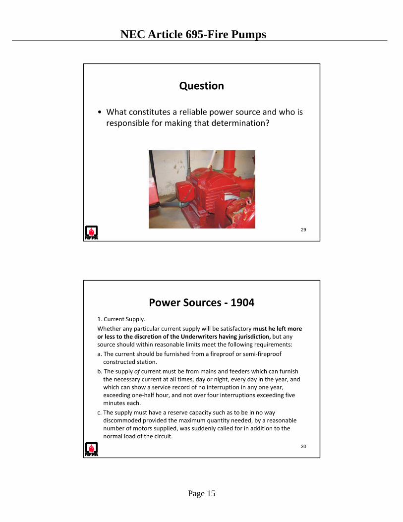
Question
• What constitutes a reliable power source and who is responsible for making that determination?
29
Power Sources ‐ 1904
1. Current Supply.
Whether any particular current supply will be satisfactory must he left more or less to the discretion of the Underwriters having jurisdiction, but any source should within reasonable limits meet the following requirements:
a. The current should be furnished from a fireproof or semi‐fireproof constructed station.
b. The supply of current must be from mains and feeders which can furnish the necessary current at all times, day or night, every day in the year, and which can show a service record of no interruption in any one year, exceeding one‐half hour, and not over four interruptions exceeding five minutes each.
c. The supply must have a reserve capacity such as to be in no way discommoded provided the maximum quantity needed, by a reasonable number of motors supplied, was suddenly called for in addition to the normal load of the circuit.
30

Page 16
NEC Article 695-Fire Pumps
31
Individual Power Sources
• Reliable – Subject to infrequent outages
– Power quality
– Metering and Meter Disconnect Considerations
– Arranged to minimize damage (underground vs. overhead installations)
– Is typically subject to approval by the authority having jurisdiction with statutory or other authority for fire protection of buildings. (i.e. fire marshals, fire chiefs, building officials, insurance underwriters) and may or may not be under the sole jurisdiction or co‐jurisdiction of the electrical AHJ.
Question
• If a single reliable power source is not available what are the permitted power supply options?
32
Page 17
NEC Article 695-Fire Pumps
33
Multiple Source Combinations for Reliable Power
• Permitted combinations for single buildings
– One service plus an “on‐site” standby generator.
– Two utility services.
– One utility service and an on‐site power production facility
• Permitted combinations for multibuilding campus complexes
– Any of the combinations permitted for single buildings
– Two feeders (supplied from different services)
– One feeder plus an on‐site standby generator
On‐Site Standby Generator 695.3 (D)
• (D) On‐Site Standby Generator as Alternate Source. An on‐site standby generator(s) used as an alternate source of power shall comply with (D)(1) through (D)(3). [20:9.6.2.1]
• (1) Capacity. The generator shall have sufficient capacity to allow normal starting and running of the motor(s) driving the fire pump(s) while supplying all other simultaneously operated load(s). [20:9.6.1.1]
• Automatic shedding of one or more optional standby loads in order to comply with this capacity requirement shall be permitted.
• (2) Connection. A tap ahead of the generator disconnecting means shall not be required. [20:9.6.1.2]
34
Page 18
NEC Article 695-Fire Pumps
35
Multiple Power Source Combinations – NFPA 20
• Other permitted combinations:– One of the approved power sources and a redundant fire pump
driven by a diesel engine complying with Chapter 11
– One of the approved power sources and a redundant fire pump driven by a steam turbine complying with Chapter 13
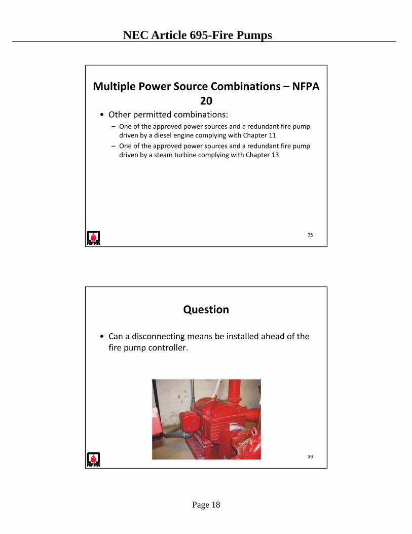
Question
• Can a disconnecting means be installed ahead of the fire pump controller.
36
Page 19
NEC Article 695-Fire Pumps
37
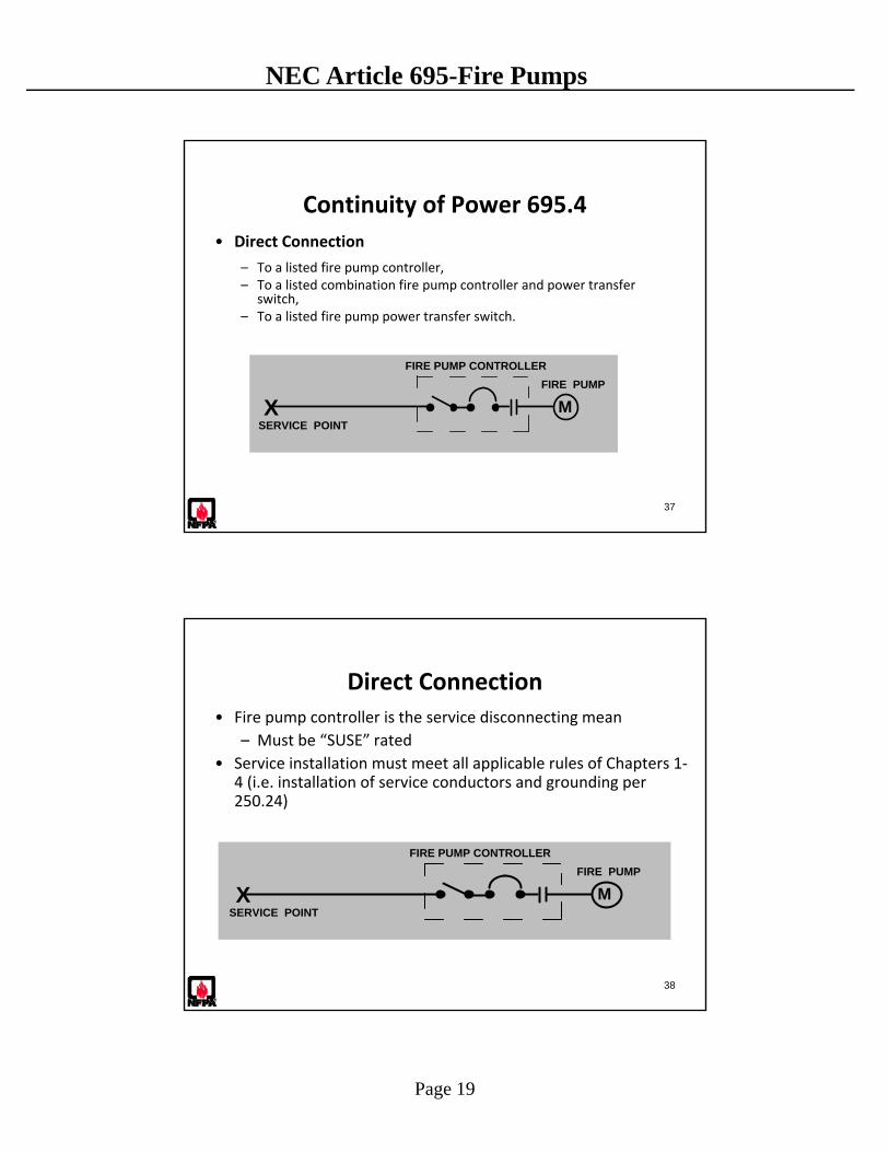
Continuity of Power 695.4
• Direct Connection
– To a listed fire pump controller, – To a listed combination fire pump controller and power transfer
switch, – To a listed fire pump power transfer switch.
M
FIRE PUMP CONTROLLER
XSERVICE POINT
FIRE PUMP
38
Direct Connection
• Fire pump controller is the service disconnecting mean
– Must be “SUSE” rated
• Service installation must meet all applicable rules of Chapters 1‐4 (i.e. installation of service conductors and grounding per 250.24)
M
FIRE PUMP CONTROLLER
XSERVICE POINT
FIRE PUMP
Page 20
NEC Article 695-Fire Pumps
39
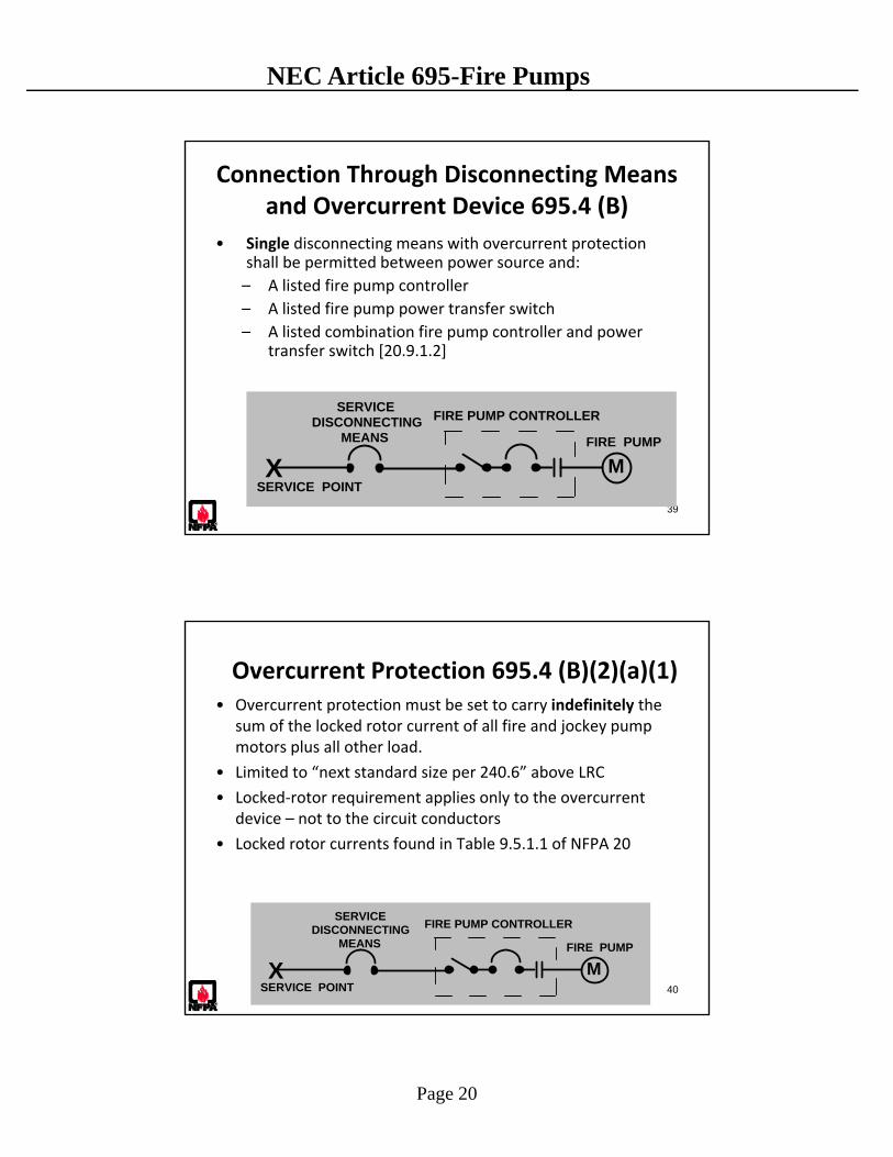
Connection Through Disconnecting Means and Overcurrent Device 695.4 (B)
• Single disconnecting means with overcurrent protection shall be permitted between power source and:
– A listed fire pump controller
– A listed fire pump power transfer switch
– A listed combination fire pump controller and power transfer switch [20.9.1.2]
FIRE PUMP CONTROLLER
FIRE PUMP
XSERVICE POINT
SERVICE DISCONNECTING
MEANS
M
40
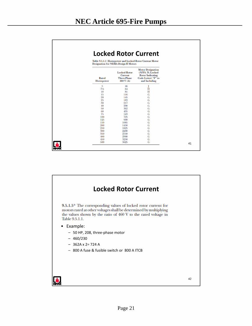
Overcurrent Protection 695.4 (B)(2)(a)(1)• Overcurrent protection must be set to carry indefinitely the
sum of the locked rotor current of all fire and jockey pump motors plus all other load.
• Limited to “next standard size per 240.6” above LRC
• Locked‐rotor requirement applies only to the overcurrent device – not to the circuit conductors
• Locked rotor currents found in Table 9.5.1.1 of NFPA 20
FIRE PUMP CONTROLLER
FIRE PUMP
XSERVICE POINT
SERVICE DISCONNECTING
MEANS
M
Page 21
NEC Article 695-Fire Pumps
Locked Rotor Current
41
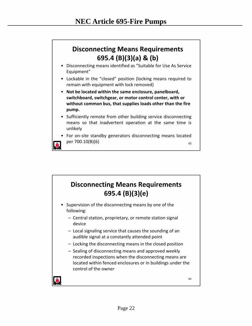
Locked Rotor Current
42
• Example:– 50 HP, 208, three‐phase motor
– 460/230
– 362A x 2= 724 A
– 800 A fuse & fusible switch or 800 A ITCB
Page 22
NEC Article 695-Fire Pumps
43
Disconnecting Means Requirements 695.4 (B)(3)(a) & (b)
• Disconnecting means identified as “Suitable for Use As ServiceEquipment”
• Lockable in the “closed” position (locking means required toremain with equipment with lock removed)
• Not be located within the same enclosure, panelboard, switchboard, switchgear, or motor control center, with or without common bus, that supplies loads other than the fire pump.
• Sufficiently remote from other building service disconnectingmeans so that inadvertent operation at the same time isunlikely
• For on‐site standby generators disconnecting means locatedper 700.10(B)(6)
44
Disconnecting Means Requirements 695.4 (B)(3)(e)
• Supervision of the disconnecting means by one of the following:
– Central station, proprietary, or remote station signal device
– Local signaling service that causes the sounding of an audible signal at a constantly attended point
– Locking the disconnecting means in the closed position
– Sealing of disconnecting means and approved weekly recorded inspections when the disconnecting means are located within fenced enclosures or in buildings under the control of the owner
Page 23
NEC Article 695-Fire Pumps
45
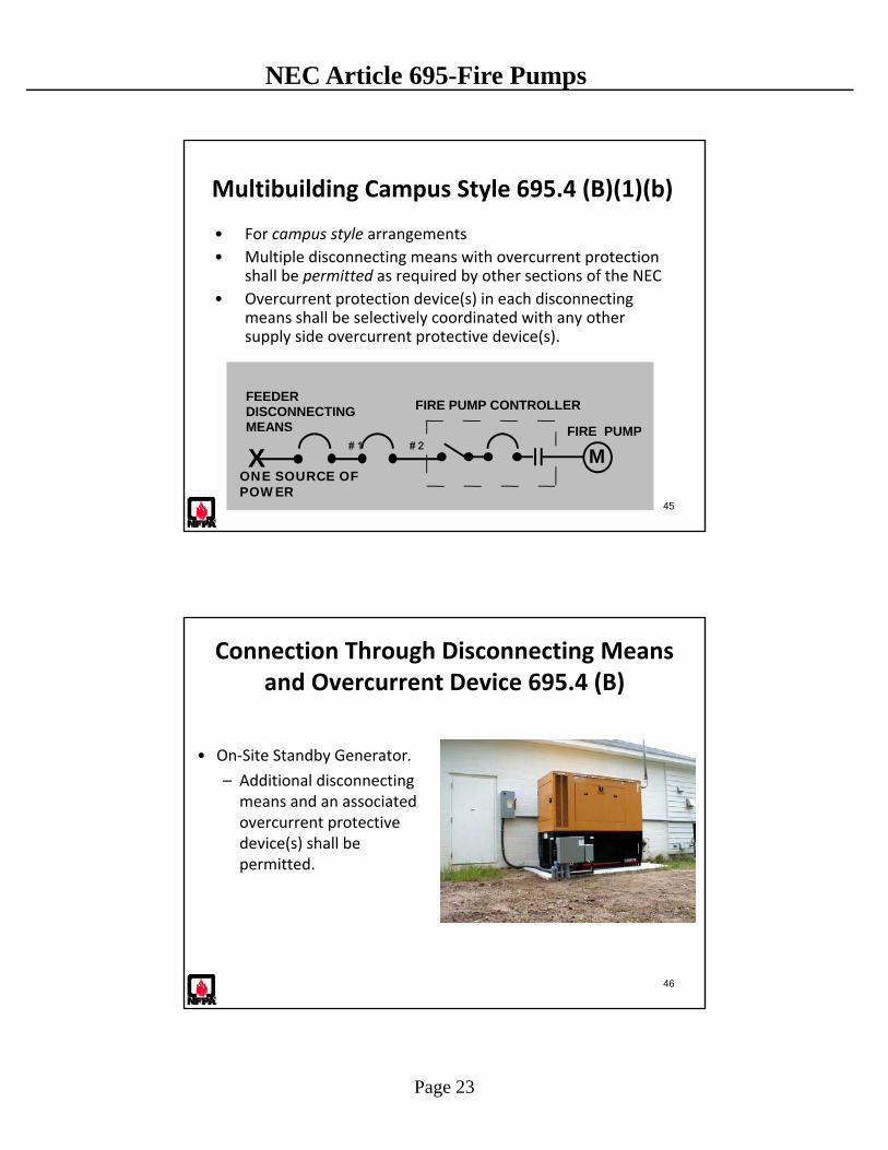
Multibuilding Campus Style 695.4 (B)(1)(b)
• For campus style arrangements
• Multiple disconnecting means with overcurrent protection shall be permitted as required by other sections of the NEC
• Overcurrent protection device(s) in each disconnecting means shall be selectively coordinated with any other supply side overcurrent protective device(s).
FIRE PUMP CONTROLLER
FIRE PUMP
XONE SOURCE OFPOWER
FEEDERDISCONNECTINGMEANS
M# 1 # 2
Connection Through Disconnecting Means and Overcurrent Device 695.4 (B)
• On‐Site Standby Generator.
– Additional disconnecting means and an associated overcurrent protective device(s) shall be permitted.
46

Page 24
NEC Article 695-Fire Pumps
47
Generator Overcurrent Protection 695.4 (B)(2)(b)
• Overcurrent protective devices between an on‐site standby generator and a fire pump controller:
– Sized to allow for instantaneous pickup of the full pump room load,
– Shall not be larger than the value selected to comply with 430.62 to provide short‐circuit protection only.
Question
• What are the conductor installation and sizing requirements for a fire pump service and/or feeder?
48
Page 25
NEC Article 695-Fire Pumps
49
Circuit Conductors – 695.6
• Service conductors
• Circuit (feeder and branch) conductors
• Pump room wiring methods
• Conductor sizing
• Overcurrent protection
• Junction points
• Control wiring
50
Utility Service and On‐site Power Production Source Conductors 695.6 (A)
• Physically routed outside the building, and installed as serviceentrance conductors.
• Permitted to be routed through building if installed under, orenclosed within, not less than 2 inches of concrete (230.6(1)or (2))
Page 26
NEC Article 695-Fire Pumps
51
Circuit Conductors 695.6 (A) (2)
• Applies to feeders and branch circuits on the load side of the final disconnecting means or conductors connected directly to output terminals of standby generator:
– Shall be kept entirely independent of all other wiring.
– Shall supply only loads that are directly associated with the fire pump system,
– Shall be protected to resist potential damage by fire, structural failure, or operational accident.
52
Circuit Conductors 695.6 (A) (2)
If necessary to route fire pump conductors inside a building conductors shall be:
• Be encased in a minimum 50 mm (2 in.) of concrete
• Be protected by a fire‐rated assembly listed to achieve a minimum fire rating of 2 hours and dedicated to the fire pump circuit(s)
• Be a listed electrical circuit protective system with a minimum 2‐hour fire rating
Page 27
NEC Article 695-Fire Pumps
Circuit Conductors 695.6 (A) (2)
53
Circuit Conductors 695.6 (A) (2)
54

Page 28
NEC Article 695-Fire Pumps
Circuit Conductors 695.6 (A) (2)
55
Circuit Conductors 695.6 (A) (2)
56
Page 29
NEC Article 695-Fire Pumps
57
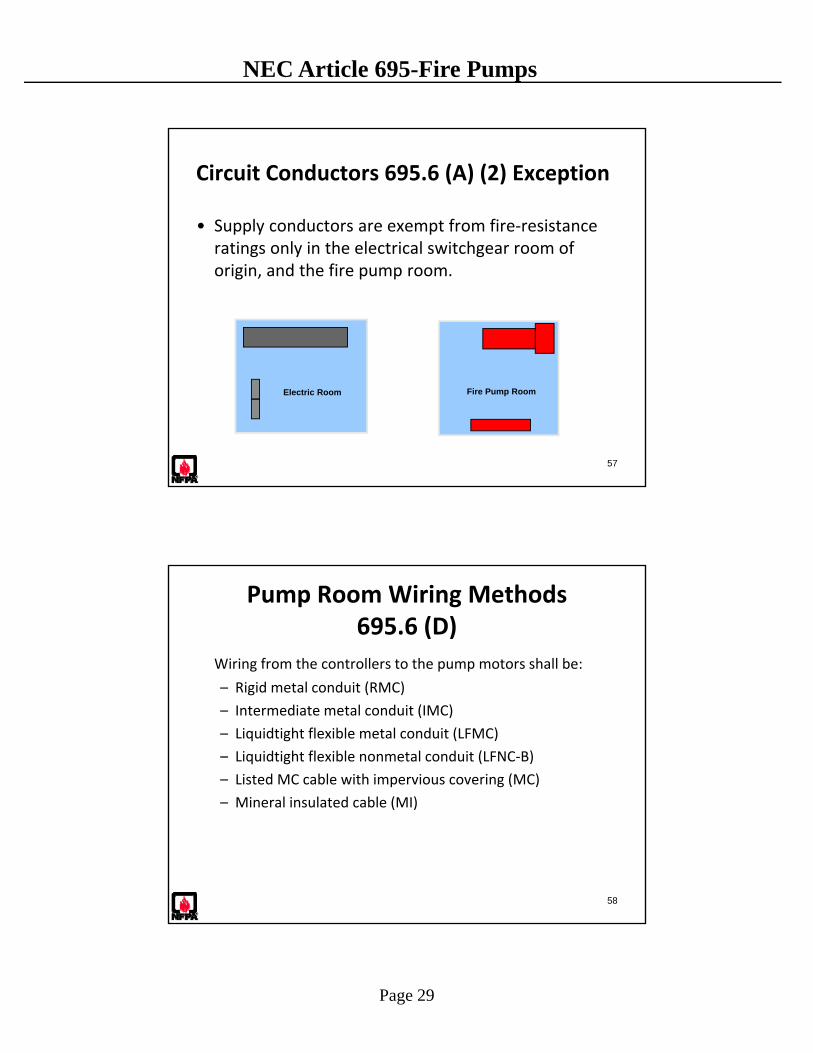
Circuit Conductors 695.6 (A) (2) Exception
• Supply conductors are exempt from fire‐resistance ratings only in the electrical switchgear room of origin, and the fire pump room.
Electric Room Fire Pump Room
58
Pump Room Wiring Methods 695.6 (D)
Wiring from the controllers to the pump motors shall be:
– Rigid metal conduit (RMC)
– Intermediate metal conduit (IMC)
– Liquidtight flexible metal conduit (LFMC)
– Liquidtight flexible nonmetal conduit (LFNC‐B)
– Listed MC cable with impervious covering (MC)
– Mineral insulated cable (MI)
Page 30
NEC Article 695-Fire Pumps
59
Conductor Size for Fire Pump 695.6 (B)
125% of fire pump(s) FLC
+ 125% of jockey pump(s)
+ 100% of other equipment
Or, just 125% of fire pump FLC if only fire pump load(s)
60
Voltage Drop 695.7
Performance requirements to assure the initial power circuit installation is satisfactory
At controller line terminals:
• During normal starting conditions, a 15% volt drop is the maximum vd permitted.
• During 115% of run condition, a 5% voltage drop is the maximum vd permitted.
Page 31
NEC Article 695-Fire Pumps
61
Overcurrent Protection 695.6 (C)
General Rules: • Short circuit protection only• No overload protection• Ground fault protection of equipment not permitted for fire
pumps.• Taps made to supply a fire pump shall be treated as service
conductors in accordance with 230.6. – The applicable distance and size restrictions in 240.21 shall not apply.
• Conductors directly connected to generator with output greater than 2.25 times FLC of fire pump, conductors are to be installed per 695.6 (A) (2)
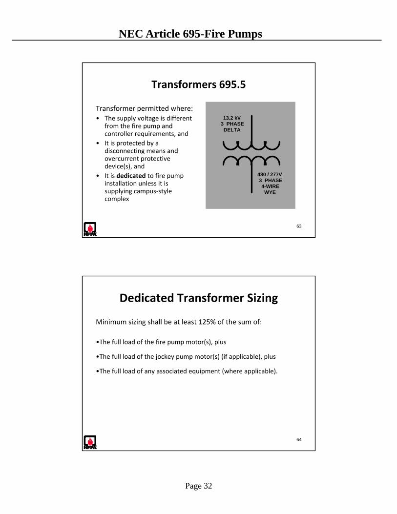
Question
• Does Article 695 cover installations where the fire pump utilization voltage differs from the supply voltage to the premises?
62
Page 32
NEC Article 695-Fire Pumps
63
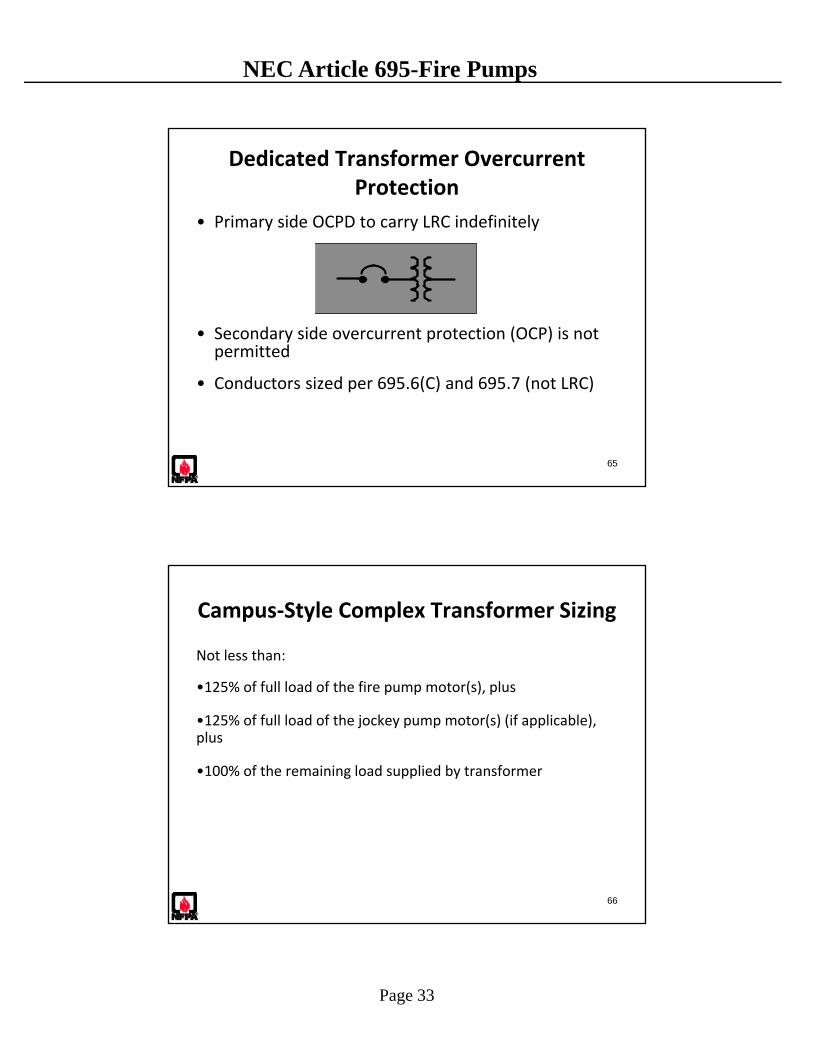
Transformers 695.5
Transformer permitted where: • The supply voltage is different
from the fire pump and controller requirements, and
• It is protected by a disconnecting means and overcurrent protective device(s), and
• It is dedicated to fire pump installation unless it is supplying campus‐style complex
13.2 kV 3 PHASE DELTA
480 / 277 V 3 PHASE 4-WIRE WYE
64
Dedicated Transformer Sizing
Minimum sizing shall be at least 125% of the sum of:
•The full load of the fire pump motor(s), plus
•The full load of the jockey pump motor(s) (if applicable), plus
•The full load of any associated equipment (where applicable).
Page 33
NEC Article 695-Fire Pumps
65
Dedicated Transformer Overcurrent Protection
• Primary side OCPD to carry LRC indefinitely
• Secondary side overcurrent protection (OCP) is not permitted
• Conductors sized per 695.6(C) and 695.7 (not LRC)
66
Campus‐Style Complex Transformer Sizing
Not less than:
•125% of full load of the fire pump motor(s), plus
•125% of full load of the jockey pump motor(s) (if applicable), plus
•100% of the remaining load supplied by transformer

Page 34
NEC Article 695-Fire Pumps
Campus‐Style Complex Transformer Overcurrent Protection
Transformer, feeder conductors and overcurrent protection shall be coordinated so that :
• Transformer is protected per 450.3
• Feeder conductors are protected per 215.3
• Overcurrent protection devices will carry indefinitely sum of:– Locked‐rotor current of fire pump motor(s)
– Locked‐rotor current of pressure maintenance pump motors
– Full‐load current of associated fire pump accessory equipment, and
– Remaining load supplied by transformer at 100%
– Locked‐rotor requirement does not apply to feeder conductors
67
Question
• Can a fire pump controller or transfer switch be used as a location to make a tap to supply a pressure maintenance (jockey) pump or other fire pump related equipment?
68
Page 35
NEC Article 695-Fire Pumps
69
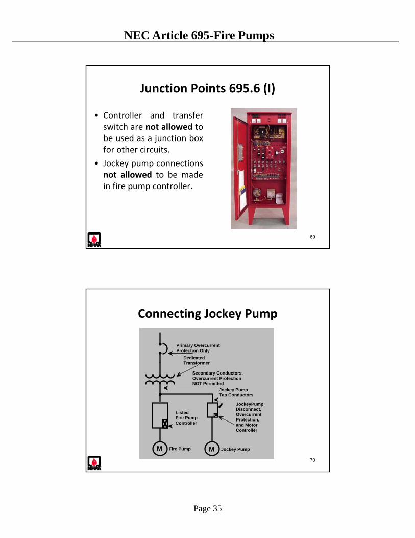
Junction Points 695.6 (I)
• Controller and transferswitch are not allowed tobe used as a junction boxfor other circuits.
• Jockey pump connectionsnot allowed to be madein fire pump controller.
70
MM
JockeyPump Disconnect, Overcurrent Protection, and Motor Controller
Jockey PumpFire Pump
Listed Fire Pump Controller
Primary Overcurrent Protection Only
Dedicated Transformer
Jockey Pump Tap Conductors
Secondary Conductors, Overcurrent Protection NOT Permitted
Connecting Jockey Pump
Page 36
NEC Article 695-Fire Pumps
Raceway Connections to Controller Enclosure 695.6 (J)
• Listed conduit hubs shall be used. [20:9.9.1]
• The type rating of the conduit hub(s) shall be at least equal to that of the fire pump controller. [20:9.9.2]
• The installation instructions of the manufacturer of the fire pump controller shall be followed. [20:9.9.3]
• Alterations to the fire pump controller, other than conduit entry as allowed elsewhere in this Code, shall be approved by the authority having jurisdiction. [20:9.9.4]
71
Listed Electrical Circuit Protective System to Controller Wiring 695.6 (H)
• Shall comply with any restrictions provided in the listing of the electrical circuit protective system used
• Junction box shall be installed ahead of the fire pump controller a minimum of 300 mm (12 in.) beyond the fire‐rated wall or floor bounding the fire zone.
• If required by the manufacturer of a listed electrical circuit protective system or by the listing, or as required elsewhere in this Code, the raceway between a junction box and the fire pump controller shall be sealed at the junction box end as required and in accordance with the instructions of the manufacturer. [20:9.8.2]
• Standard wiring between the junction box and the controller permitted. [20:9.8.3] 72
Page 37
NEC Article 695-Fire Pumps
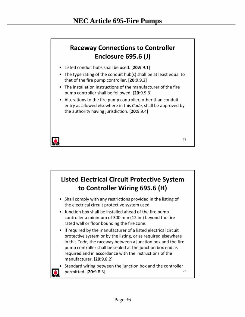
Listed Electrical Circuit Protective System to Controller Wiring – NFPA 20 9.8
73
Junction Boxes 695.6 (I)
• Junction boxes shall be securely mounted. [20:9.7(1)]
• Mounting and installing of a junction box shall not violate the enclosure type rating of the fire pump controller(s). [20:9.7(2)]
• Mounting and installing of a junction box shall not violate the integrity of the fire pump controller (s) and shall not affect the short‐circuit rating of the controller(s). [20:9.7(3)]
• As a minimum, a Type 2, drip‐proof enclosure (junction box) shall be used where installed in the fire pump room.
• Enclosure shall be listed to match the fire pump controller enclosure type rating. [20:9.7(4)]
74
Page 38
NEC Article 695-Fire Pumps
75
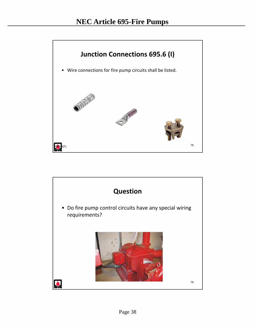
Junction Connections 695.6 (I)
• Wire connections for fire pump circuits shall be listed.
695.6(F)
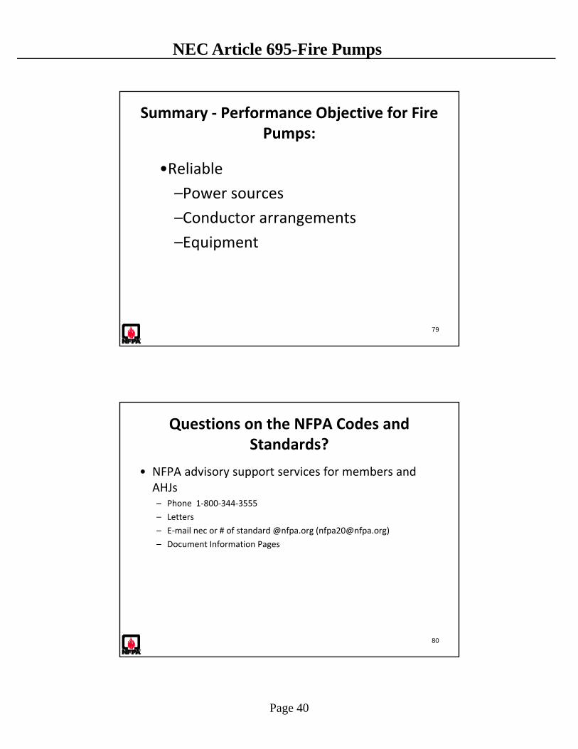
Question
• Do fire pump control circuits have any special wiring requirements?
76

Page 39
NEC Article 695-Fire Pumps
77
Fire Pump Control Wiring Methods 695.14 (E)
• RMC and IMC conduit
• LFMC and LFNC‐B flexible conduit
• MI cable
• Listed MC cable with impervious covering
695.14(E)
78
Generator Control Wiring Methods 695.14 (F)
• Between fire pump controller and standby generator
• Separate from all other wiring
• Resist damage from fire and structural failure
• If routed through the building:
– Encased in 50 mm. of concrete, or
– Within 2 hr. dedicated construction, or
– Within 2 hr. circuit protective system
695.14(F)
Page 40
NEC Article 695-Fire Pumps
79
Summary ‐ Performance Objective for Fire Pumps:
•Reliable
–Power sources
–Conductor arrangements
–Equipment
80
Questions on the NFPA Codes and Standards?
• NFPA advisory support services for members and AHJs– Phone 1‐800‐344‐3555
– Letters
– E‐mail nec or # of standard @nfpa.org ([email protected])
– Document Information Pages