2016 Crosby General Catalog English Imperial [email protected] • (918) 834-4611, Fax:...
28
McKISSICK SHEAVES McKissick ® Sheaves With Product Warnings and Application Information
Transcript of 2016 Crosby General Catalog English Imperial [email protected] • (918) 834-4611, Fax:...

McKISSICKSHEAVES
McKissick® Sheaves
W i t h P r o d u c t W a r n i n g s a n d A p p l i c a t i o n I n f o r m a t i o n

Copyright © 2016 The Crosby Group LLC All Rights Reserved278
Remember: “When buying Crosby, you’re buying more than product, you’re buying Quality.”
HISTORY & EXPERIENCE The ability to match the sheave design and manufacturing
process to meet the application requirements requires
experience. It also requires the ability to creatively use this
experience and manufacturing resources to provide the
best solution.
DELIVERY & ACCESSIBILITY Many energy and lifting sheave applications require short
delivery times and delivery to locations around the world.
Access around the world requires not only logistics
experience and capabilities, but also requires manufacturing
resources strategically located around the world.
FLEXIBILITY OF DESIGN Matching the best solution to the application requires the
ability to fabricate sheaves by a number of processes:
1) Heavy Duty – Roll forged sheaves are hot forged with no
splitting stresses at base for sheaves up to 78”.
2) Heavy Duty – Closed die forged sheaves with machined
Wireline groove for sheaves up to 16”.
3) Extreme Duty – Roll forged sheaves with welded dome
reinforcement employ the latest welding technology with
no shape cross brace stress concentration areas.
4) Heavy Duty fabricated sheaves – With welded rings and
reinforced webs utilizing the latest welding technology.
5) The ability to provide sheave grooves with 30, 35 and 45
6) The ability to provide bearings to match application:
Plain bore, bronze bushed, roller bearings, tapered
roller bearings and full complement bearings.
7) Heat treatment of Wireline groove to provide wear
resistance.
SPECIFICATIONS Many energy and lifting sheaves must meet standards.
These standards include API, ABS, DIN, DNV and ASME.
applications also include strength, fatigue, impact and non-
destructive testing.
TECHNICAL SUPPORT & TRAINING The selection, use, inspection and maintenance of sheaves
requires technical support. This technical support includes
engineering services, training support and the ability to
meet the various industry requirements around the world.
McKissick has provided sheaves to energy and lifting
industries since the early 1900’s. Since McKissick became
part of Crosby in the mid 1900’s there has been a continuous
history of product and process development. Crosby invented
the roll forged sheave in 1978 and continues to be a leader
today in sheave design and manufacturing process.
Crosby-McKissick stocks key raw materials and has an
capacity to support short deliveries. Crosby has McKissick
block and sheave centers that serve their local markets in
Tulsa, Oklahoma (USA); Putte, Belgium; Singapore; and
Hangzhou, China.
McKissick offers roll forged sheaves that provide an upset
point. The dome-reinforced sheave design provides for a
continuous weld in a circular pattern. McKissick produces
underwater and in harsh and demanding environments
gives McKissick the needed experience in selecting sheaves
for all applications. From material selection to hardening of
the groove, McKissick sheaves provide the needed wire-
line life.
Ask: How do they support short deliveries?
Ask: What is their experience providing worldwide delivery?
Ask: What resources do they have in key areas of the world?
Ask: Do they understand and have experience in meeting the industry standards such as API, ABS, DIN, DNV and ASME?
Ask: Do they have a history of gaining required approvals?
Ask: Are they licensed to manufacture sheaves to API 8C?
Ask: What technical support do they provide?
Ask: Where is this support provided from?
Ask: What training is available to support the selection, use, inspection and maintenance of sheaves?
Ask: What is their history and experience?
Ask: What processes do they have available to draw upon?
Ask: What technical experience do they have available to provide technical solutions to technical demands?
Ask: How do they achieve the performance required with a split or cast sheave?
Ask: How do they resolve the welding stresses induced when you fabricate the sheave?
Ask: What sheave groove profile do they provide on a regular basis?
Ask: Do they have technical expertise to recommend proper sheave bearings?
Ask: How do they provide for proper Wireline groove life?
THE COMPETITION
THE COMPETITION
THE COMPETITION
THE COMPETITION
THE COMPETITION
Crosby McKissick has achieved API Q1, and TS29001
Status, and is licensed to manufacture sheaves to API
8C. Sheaves are frequently provided to API, DNV and
ABS requirements.
Crosby has technical and operational support available
from each of our McKissick Block and Sheave Centers
around the world. Crosby provides extensive training
though our one day Block and Sheave Clinics and our
is also provided.
The Market Leader: Yesterday Today and Tomorrow
"There is No Equal"
McKissick Sheaves
279
PO
LE
AS
McK
ISS
ICK
®
Copyright © 2016 The Crosby Group LLC Todos los Dereches Reservados
30˚45˚ 35˚
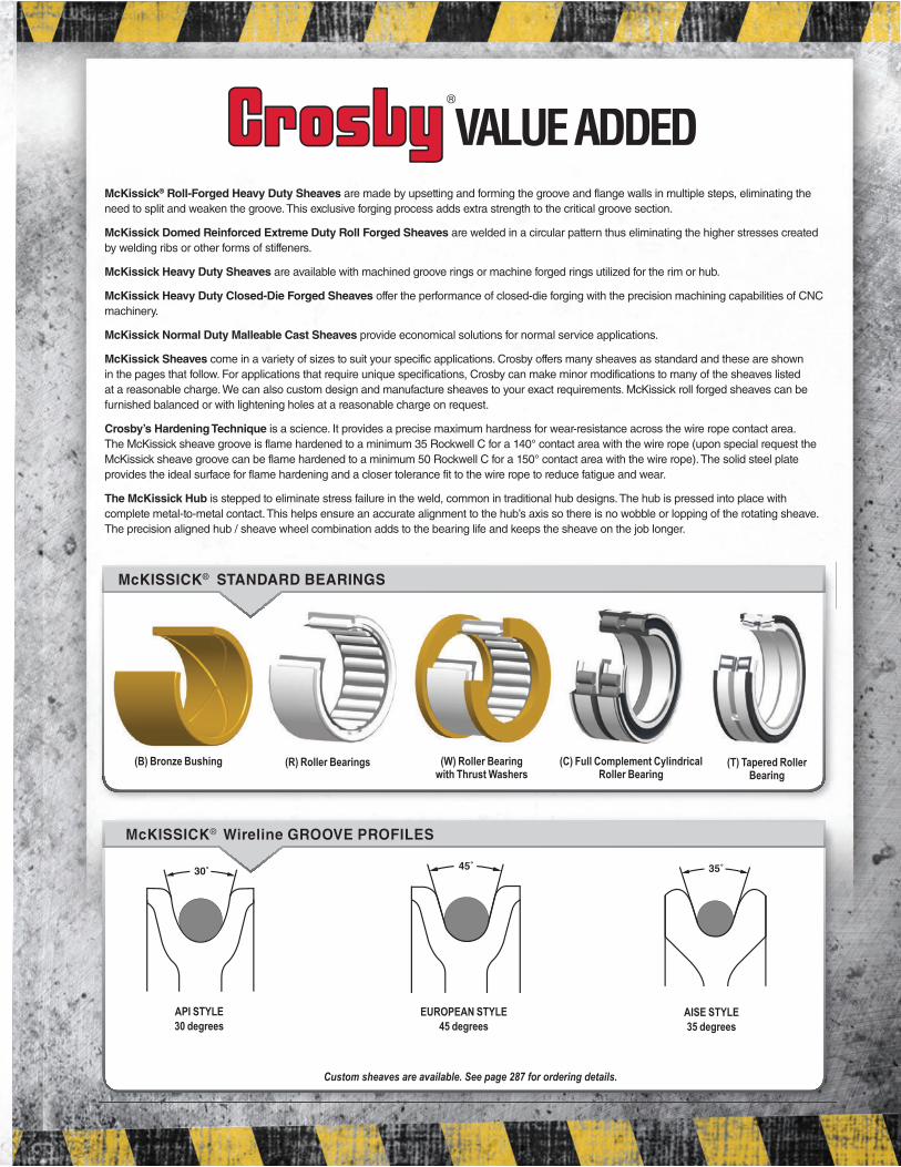
McKissick® Roll-Forged Heavy Duty Sheaves are made by upsetting and forming the groove and flange walls in multiple steps, eliminating the
need to split and weaken the groove. This exclusive forging process adds extra strength to the critical groove section.
McKissick Domed Reinforced Extreme Duty Roll Forged Sheaves are welded in a circular pattern thus eliminating the higher stresses created
by welding ribs or other forms of stiffeners.
McKissick Heavy Duty Sheaves are available with machined groove rings or machine forged rings utilized for the rim or hub.
McKissick Heavy Duty Closed-Die Forged Sheaves offer the performance of closed-die forging with the precision machining capabilities of CNC
machinery.
McKissick Normal Duty Malleable Cast Sheaves provide economical solutions for normal service applications.
McKissick Sheaves come in a variety of sizes to suit your specific applications. Crosby offers many sheaves as standard and these are shown
in the pages that follow. For applications that require unique specifications, Crosby can make minor modifications to many of the sheaves listed
at a reasonable charge. We can also custom design and manufacture sheaves to your exact requirements. McKissick roll forged sheaves can be
furnished balanced or with lightening holes at a reasonable charge on request.
Crosby’s Hardening Technique is a science. It provides a precise maximum hardness for wear-resistance across the wire rope contact area.
The McKissick sheave groove is flame hardened to a minimum 35 Rockwell C for a 140° contact area with the wire rope (upon special request the
McKissick sheave groove can be flame hardened to a minimum 50 Rockwell C for a 150° contact area with the wire rope). The solid steel plate
provides the ideal surface for flame hardening and a closer tolerance fit to the wire rope to reduce fatigue and wear.
The McKissick Hub is stepped to eliminate stress failure in the weld, common in traditional hub designs. The hub is pressed into place with
complete metal-to-metal contact. This helps ensure an accurate alignment to the hub’s axis so there is no wobble or lopping of the rotating sheave.
The precision aligned hub / sheave wheel combination adds to the bearing life and keeps the sheave on the job longer.
Custom sheaves are available. See page 287 for ordering details.
McKISSICK® Wireline GROOVE PROFILES
API STYLE
30 degrees
EUROPEAN STYLE
45 degrees
AISE STYLE
35 degrees
McKISSICK® STANDARD BEARINGS
(W) Roller Bearing with Thrust Washers
(C) Full Complement Cylindrical Roller Bearing
(T) Tapered Roller Bearing
(R) Roller Bearings(B) Bronze Bushing
McKISSICK® Wireline GROOVE PROFILES
VALUE ADDED

The Elements of a Superior Sheave.
McKissick® Cold Formed Split Steel
Smooth Radius Edge - Better fit, less wear on rope 4
Thicker Fleet Section - Better support, stronger sheave groove 4
Deep Penetrating Weld at Hub - Longer life 4
Flame Hardened Groove - Higher Rockwell C rating 35Rc 14Rc
Roll Forging Process - Provides superior grain flow 4
Roll-Forged Sheave
Every McKissick® Roll-Forged sheave starts as a single piece of AISI C-1035
carbon steel plate. Utilizing a “time proven” proprietary roll forging process that adds
extra strength to the critical groove section, the sheave is formed from a precision
flame cut blank. The hub is then pressed into place with complete metal-to-metal
contact and secured with a deep penetrating weld to ensure proper fit and longer
life. Before the McKissick® name is added, each sheave is thoroughly inspected to
meet applicable industry and Crosby® quality standards.
McKissick® Roll-Forged sheaves contain the following critical standard features required to
meet your demanding applications.
1
2
3
1
2 5
4
3
6
There is no sheave like a McKissick® Roll-Forged Sheave
®
®
®
Thicker web on sheave provides required stiffness to
support a stronger sheave that contains thicker flange sections
- The thinner web on cold formed split steel sheaves, inherent
to the process, does not support thicker flange sections
- The sharp, pointed cutter used in forming the groove during the cold
formed split steel process may produce a concealed crack in the
bottom of the groove
Size for size, McKissick® Roll-Forged sheaves
have a thicker section under the tread
of the Wireline groove - providing more
substantial support of the Wireline
- Cold formed split steel sheaves are limited
to a thinner section thickness under the groove,
reducing sheave life in heavy service conditions
- Thinner sections produce a sharp corner
under the tread, resulting in potential stress risers
Smooth radius at the rim provides superior
transition from outside diameter to groove -
eliminating sharp corners that can damage rope
- Cold formed split steel sheaves may contain
a sharp transition radius at rim of sheave
DO NOT BE FOOLED

E-mail: [email protected] • (918) 834-4611, Fax: (918) 832-0940
www.thecrosbygroup.com
Crosby® and McKissick® Roll-Forged Sheaves
Reliability You Can Depend On
Cold Formed Split Steel Sheave
Minimum 35Rc for higher hardness in the bottom of
the groove - results in less wear to the sheave, thus
extending life of Wireline
- Unless requested at time of order, cold formed split
steel sheaves have a much lower hardness rating
(approx. 14Rc)
- The standard material used in cold formed split steel
process may not allow higher hardness in groove
Heavier flange sections - provide a much stronger wire
rope groove and maintain proper consistent groove
angles, ensuring long term Wireline performance
- Cold formed split steel sheaves tend to have flange
sections that are thinner as well as variations in
thickness on the same sheave, resulting in less than
desired performance during critical applications
- Cold formed split steel sheaves are limited to a
maximum flange thickness of 50% of web section
Additional Important Features of McKissick® Roll-Forged Sheaves
The grain flow associated with the McKissick® Roll-Forged sheave
process results in excellent performance properties.
Each sheave is permanently marked with “McKissick®”, sheave
outside diameter, Wireline size and Product Identification Code (PIC)
that provides complete material traceability.
Precision alignment of hub with blank, then finished
with a deep penetrating weld - ensuring proper fit,
longer life and confidence during the most extreme
of applications
6
5
4®
®
®
...into thinking all sheaves produce the same results.

Copyright © 2016 The Crosby Group LLC All Rights Reserved
McK
ISS
ICK
®
SH
EA
VE
S
282
NOTE: Custom Sheaves are Available.See Page 287 for Ordering Details.
McKissick® Roll-Forged™ Sheaves
Stepped Hub Design Proves Better
The McKissick hub is stepped to eliminate stress failure in the weld, common in traditional hub designs. The hub is pressed into place with complete metal-to-metal contact. This helps ensure an accurate alignment to the hub’s axis so there is no wobble or lopping of the rotating sheave. The precision aligned hub/sheave wheel combination adds to the bearing life and keeps the sheave on the job longer.
Full Range of Standard Sheave Sizes
McKissick Roll-Forged sheaves are available in a full range of sizes from 12 inches to 78 inches, and bearing styles and prices that best
custom McKissick sheaves and can make minor
special applications.
Flame Hardened Groove
Crosby’s hardening technique is a science. It provides a precise maximum hardness for wear-resistance across the wire rope contact area. The McKissick sheave groove
C for a 140° contact area with the wire rope (upon special request the McKissick sheave
50 Rockwell C for a 150° contact area with the wire rope). The solid steel plate provides the
and wear.
Closed Die Upset and Roll Forged – Not Split
Upsetting and roll forging forms the groove
the need to split and weaken the groove. This exclusive forging process adds extra strength to the critical groove section. You can count on a McKissick sheave to give maximum life performance, because it’s forged to distribute the wire rope forces evenly over an accurately formed load surface. Plus, uniformity of the roll forged groove adds longer wire rope life.
Solid Steel – No Casting
Every McKissick sheave starts as a single piece
closely checked stock, so there’s no inherent
There’s better balance and better distribution of forces with a McKissick Roll-Forged sheave too. Casting can result in groove wall variations – either too thick or too thin – causing uneven stresses and early failure.
Bearing Selection to Match
Your Job Requirement
The McKissick Roll-Forged sheave is available
• Plain bore
• Bronze bushed
• Roller bearing
• Tapered roller bearing
• Lubrication thru hub
• Key ways
• Set screws
• Full Complement Bearing
Sheaves are available to API 8C.
HEAVY DUTY SHEAVES FROM 12” THROUGH 78”
Full penetration weld is standard on 40” and larger sheaves.
McK
ISS
ICK
®
SH
EA
VE
S
Copyright © 2016 The Crosby Group LLC All Rights Reserved 283
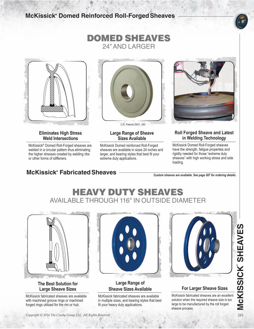
McKissick® Domed Reinforced Roll-Forged Sheaves
McKissick® Fabricated Sheaves
DOMED SHEAVES 24” AND LARGER
HEAVY DUTY SHEAVES AVAILABLE THROUGH 116" IN OUTSIDE DIAMETER
Eliminates High Stress Weld Intersections
McKissick® Domed Roll-Forged sheaves are welded in a circular pattern thus eliminating the higher stresses created by welding ribs or other forms of stiffeners.
Large Range of Sheave Sizes Available
McKissick Domed reinforced Roll-Forged sheaves are available in sizes 24 inches and
extreme duty applications.
Roll Forged Sheave and Latest in Welding Technology
McKissick Domed Roll-Forged sheaves have the strength, fatigue properties and rigidity needed for those “extreme duty sheaves” with high working stress and side loading.
U.S. Patents D621, 240
The Best Solution forLarge Sheave Sizes
McKissick fabricated sheaves are available with machined groove rings or machined forged rings utilized for the rim or hub.
Large Range of
Sheave Sizes Available
McKissick fabricated sheaves are available in multiple sizes, and bearing styles that best
For Larger Sheave Sizes
McKissick fabricated sheaves are an excellent solution when the required sheave size is too large to be manufactured by the roll forged sheave process.
Custom sheaves are available. See page 287 for ordering details.

Copyright © 2016 The Crosby Group LLC All Rights Reserved
McK
ISS
ICK
®
SH
EA
VE
S
284
McKissick® Ductile Iron Sheaves
HEAVY DUTY SHEAVES FROM 4" THROUGH 12"
NORMAL SERVICE DUTY SHEAVES FROM 3" THROUGH 16"
Closed Die Forging
McKissick closed die forged sheaves offer the performance of closed die forging with the precision machining capabilities of CNC machinery.
Select Range of Sheave Sizes Available
McKissick closed die forged sheaves are available in sizes from 4 inches to 12 inches,
duty applications.
Machined Ductile Iron
McKissick ductile iron sheaves are manufactured with material that meets ASTM A-536.
Select Range of
Sheave Sizes Available
McKissick ductile iron sheaves are available in sizes from 3 inches to 16 inches, and
service duty applications.
For Smaller Sheaves in Heavy Duty Application
McKissick closed die forged sheaves
are available in sizes from 4 inches to
12 inches. An extremely effective
solution for heavy duty applications
where high loads are applied.
Any of the bearings we offer with the
roll forged sheaves are available.
McKissick® Closed Die Forged Sheaves
For Smaller Sheavesin Normal Duty Applications
McKissick ductile iron sheaves are an
acceptable solution for light or normal
duty applications where sheaves
are protected by sheave guards and
minimal side loads are applied.
Standard roller bearings and bronze
bushings are typically appropriate for
use in these applications.
Custom sheaves are available. See page 287 for ordering details.

McK
ISS
ICK
®
SH
EA
VE
S
Copyright © 2016 The Crosby Group LLC All Rights Reserved 285
McKISSICK® Wireline GROOVE PROFILES
API STYLE
30 degrees
30˚
EUROPEAN STYLE
45 degrees
45˚
AISE STYLE
35 degrees
35˚
McKissick® Sheaves Available to API Standards
feature of all sheaves. McKissick manufactures standard sheaves for general use in hoisting wire rope guide applications to minimal API
is used in mobile cranes, drilling rigs, working units, tubing blocks, traveling blocks, crown blocks and many other general hoisting applications.
Nominal tread depth is 1.5 times wire rope diameter.
McKissick manufactures sheaves to meet the
established by the Association of Iron and Steel Engineers for special use in electric overhead traveling cranes for steel mill
overhead traveling cranes, mobile cranes, portal cranes, power shovels and other equipment using wire rope.
Contact Crosby for additional available groove angles.
• McKissick® In addition, McKissick®
• McKissick® Products also produces sheaves to the requirements of API 2C.
• API sheaves must meet the criteria established by the American Petroleum Institute for drilling and production hoisting equipment .
and Offshore Cranes.
API 8C Requires
• Databook
• Material certs and traceability
• D/d ratio per API RP9B
• MPI
• UT of full penetration weld
• 30° groove angle. Groove depth a minimum 1.33 d and maximum 1.75 d, where d=nominal rope diameter.
• Manufactured by an API-8C licensed facility
• Can be furnished to API 8C PSL1 or PSL2
API 2C Requires
• Material certs and traceability
• D/d ratio 18/1 or greater, based on pitch diameter
• At least 30° groove angle
McKissick® Sheaves Groove Profile Available

Copyright © 2016 The Crosby Group LLC All Rights Reserved
McK
ISS
ICK
®
SH
EA
VE
S
286
C
DHub
Width
Bearing
Width
Shaft
Siz
e
Bo
re S
ize
ROLLER BEARINGS Bronze Bushings with “Figure 8”
oil grooves are made from S.A.E. 660
Bronze Bushing Slow line speed, moderate load and moderate use
• Maximum Bearing Pressure (BP): 4500 PSI
• Maximum Velocity at Bearing (BV): 1200 FPM
• Maximum Pressure Velocity Factor (PV): 55000
Formula for BP = Line Pull x Angle Factor (See Page 383)
Shaft Size x Hub Width (See example)
Roller Bearings are designed
to operate on shafts carborized
to 60 Rockwell C and grounded
to +/- .0005 of shaft size.
Roller Bearings without inner races
are designed to operate on shafts
carborized to 60 Rockwell C and
grounded to +/- .0005 of shaft size.
Cylindrical Roller Bearings
with snap ring grooves are
complete units with outer and
inner rings, rib guided cylindrical
rollers and sealing rings. They
can support axial forces in both
directions a well as radial forces.
They have high dynamic and
static load ratings.
Tapered Bearings are designed
to operate on shafts machined to
+/- .0005 of shaft size. Applications
should provide for tightening
separator plates against bearing
cones to adjust and insure proper
function of bearings.
STANDARD STRAIGHT ROLLER BEARINGS
Heavier loads, higher speeds, more
frequent use, radial loads only.
For underwater sheave applications, special bronze bushings are avaiable. Consult the bearing manufacturer for applicable load.
Example: Using a 14 in. sheave (917191) with a 4600 lbs. line
pull and an 80 degree angle between lines, determine
maximum allowable line speed.
(PV Factor)
55000 BV = = 19 FPM 2896 (BP)
(Shaft Size) (Hub Width)
(Line Pull) (Angle Factor)
BP = 4600 lbs. x 1.53
1.50 x 1.62 = 2896 PSI
McKissick® Sheaves Bearings Application Information
FULL COMPLEMENT, DOUBLE ROW, ROLLER BEARING Heavy load, high speeds, continuous
operation, axial and radial loads.
TAPERED ROLLER BEARINGS
Heavy loads, high speeds, continuous
operation, axial and radial loads.
(R) Roller Bearings(W) Roller Bearing
with Thrust Washers
(B) Bronze Bushing
(C) Full Complement Cylindrical
Roller Bearing
(T) Tapered RollerBearing

McK
ISS
ICK
®
SH
EA
VE
S
Copyright © 2016 The Crosby Group LLC All Rights Reserved 287
McKissick® Sheaves
pages that follow.
also custom design and manufacture sheaves to your exact requirements. Contact Crosby Sales to order McKissick® sheaves and include the stock
important information:
In USA: Crosby’s Special Engineered Product Group at 1-800-777-1555, fax (918) 834-5035, [email protected]
In Canada: Crosby Canada at (905) 451-9261
In Europe: N.V. Crosby Europe at 32 15 757125(26).
McKissick® Sheaves Selection Guide
DIMENSIONAL INFORMATION
Nominal Outside Diameter:_____________________WireRope Size:______________________________Rim Width:_____________________
+ Shaft Size:__________________________*Hub Width:__________________________
Nominal Tread Diameter (Optional):_______________________________Nominal Hub Diameter (Optional): ____________________________
*Hub width is measured over the cone of the Tapered Bearing Sheaves.
+ Shaft Size is Bore Size on Plain Bore Sheaves.
BEARING TYPE
q Bronze Bushing q ++ Roller Bearing q Tapered Roller Bearing q Finish / Plain Bore
q Full Complement Cylindrical Roller Bearing q Underwater q Other ++ Requires hardened and ground shaft
MATERIAL TYPE
q Roll-Forged (Flame hardened 14” and larger) q Forged Steel q Domed
q Cast Steel q Fabricated q Other
APPLICATION INFORMATION
Line Pull:________________________________Fleet Angle:________________________Degree of Wrap:__________________________
Line Speed:_____________________________Environment:_______________________ Groove Angle: ____________________________
SPECIAL REQUIREMENTS
Special Testing:______________________________________________________________________________________________________
Finish:_____________________________________________________________________________________________________________
Third Party Inspection / Approval:________________________________________________________________________________________

Copyright © 2016 The Crosby Group LLC All Rights Reserved
McK
ISS
ICK
®
SH
EA
VE
S
288
McKissick® Finished Bore Sheaves
Custom sheaves are available. See page 287 for ordering details.
Finished Bore Sheaves• Roll-Forged™ sheaves are available in sizes up to 78” in diameter.
• McKissick® Finished Bore Sheaves can be equipped with bushings or bearings at an optional charge.
“A” Nominal Outside
Diameter (in.)
Stock Number
Wire Line Size (in.)
“D” Bore Size (in.)
Hub
Width (in.)
Rim
Width (in.)
“C” Nominal Hub Outside
Diameter (in.)
“B”
Nominal Tread Diameter
(in.)
Material
Approx.Weight (lbs.)
3 51008 1/4 .752 1-5/16 1-1/4 1-1/8 2-1/16 B.S. 1.00
3 11310 3/8 .752 1-5/16 1-1/4 1-1/8 2-1/16 B.S. 1.00
4 51053 1/8 1.569 1 7/8 2 3-1/8 B.S. 2.00
4 51044 1/4 1.569 1 7/8 2 3-1/8 B.S. 2.00
4 1189 3/8 1.569 1 7/8 2 3-1/8 B.S. 2.00
4 2023185 3/8 1.569 1-1/2 1-3/8 2 3 F.S. 3.50
4 2023182 1/2 1.569 1-1/2 1-3/8 2 3 F.S. 3.50
4 2023187 5/8 1.569 1-1/2 1-3/8 2 3 F.S. 3.50
4-1/4 50553 3/8 .814 1-3/16 15/16 2-1/8 3-1/8 B.S. 2.40
4-1/4 25939 1/2 814 1-3/16 15/16 2-1/8 3-1/8 B.S. 2.40
4-3/4 51222 5/16 .875 1-9/16 1-3/8 1-1/2 3-5/8 D.I. 3.50
4-3/4 51231 3/8 .875 1-9/16 1-3/8 1-1/2 3-5/8 D.I. 3.50
4-3/4 11622 1/2 .875 1-9/16 1-3/8 1-1/2 3-5/8 D.I. 3.50
4-7/8 2026411 3/8 1.749 1-1/4 1-1/8 2-1/4 4-1/16 F.S. 3.60
4-7/8 62149 3/8 1.848 1-5/16 1-1/8 2-1/4 4-1/16 F.S. 2.50
4-7/8 2026413 1/2 1.749 1-1/4 1-1/8 2-1/4 4-1/16 F.S. 3.60
4-7/8 2026409 5/8 1.749 1-1/4 1-1/8 2-1/4 4-1/16 F.S. 3.60
5 51071 5/16 1.125 1 7/8 1-1/2 4 F.S. 2.50
5 51062 3/8 1.125 1 7/8 1-1/2 4 F.S. 2.50
5 25948 7/16 1.125 1 7/8 1-1/2 4 F.S. 2.50
5-1/4 2026426 5/8 1.569 1-1/2 1-3/8 2-1/16 3-7/8 F.S. 4.00
5-1/4 2026422 3/4 1.569 1-1/2 1-3/8 2-1/16 3-7/8 F.S. 4.00
5-7/8 2023133 5/8 1.875 1-3/4 1-5/8 2-1/2 4-3/8 F.S. 6.00
5-7/8 2023136 3/4 1.875 1-3/4 1-5/8 2-1/2 4-3/8 F.S. 6.00
5-7/8 2023134 7/8 1.875 1-3/4 1-5/8 2-1/2 4-3/8 F.S. 6.00
6 51124 3/8 1.625 1-1/8 1 2-1/4 4-15/16 F.S. 4.00
6 51375 1/2 1.375 1-1/2 1-1/4 3-1/8 4-3/4 B.S. 7.00
6 13014 1/2 1.625 1-1/8 1 2-1/4 4-15/16 F.S. 4.00
6 60695 1/2 2.375 1-3/4 1-1/4 3-1/8 4-3/4 F.S. 4.70
6 2023263 5/8 2.500 2-5/16 2-3/16 3-1/8 4-1/4 F.S. 9.50
6 1410 3/4 1.375 1-1/2 1-1/4 3-1/8 4-3/4 B.S. 7.00
6 2023257 3/4 2.500 2-5/16 2-3/16 3-1/8 4-1/4 F.S. 9.50
6 2023261 7/8 2.500 2-5/16 2-3/16 3-1/8 4-1/4 F.S. 9.50
7 61872 1/4 1.848 1-5/16 3/4 2-3/8 6-1/4 B.S. 4.00
7 51437 1/4 1.875 1-3/8 3/4 2-3/8 6-1/4 B.S. 6.20
7 3203 3/8 1.875 1-3/8 3/4 2-3/8 6-1/4 B.S. 6.20
7-1/2 2026452 5/8 1.569 1-1/2 1-3/8 2-1/16 6-15/16 F.S. 7.50
7-1/2 2026450 3/4 1.569 1-1/2 1-3/8 2-1/16 6-5/16 F.S. 7.50
7-5/8 51605 3/8 1.569 1-1/2 1-1/4 2-3/8 6-3/16 D.I. 7.00
7-5/8 5498 1/2 1.569 1-1/2 1-1/4 2-3/8 6-3/16 D.I. 7.00
7-5/8 51614 5/8 1.569 1-1/2 1-1/4 2-3/8 6-3/16 D.I. 7.00
On Pages 381 - 388
SEE APPLICATION AND WARNING INFORMATION
Para Español: www.thecrosbygroup.com

McK
ISS
ICK
®
SH
EA
VE
S
Copyright © 2016 The Crosby Group LLC All Rights Reserved 289
McKissick® Finished Bore Sheaves
Custom sheaves are available. See page 287 for ordering details.
“A” Nominal Outside
Diameter (in.)
Stock Number
Wire Line Size (in.)
“D” Bore Size (in.)
Hub
Width (in.)
Rim
Width (in.)
“C” Nominal Hub Outside
Diameter (in.)
“B”
Nominal Tread Diameter
(in.)
Material
Approx.Weight (lbs.)
8 2023466 1 2.750 2-1/2 2-3/8 4 5-1/4 F.S. 15.0
8 6353 1-1/8 2.750 2-1/2 2-3/8 4 5-3/8 F.S. 15.0
8 2023152 3/4 1.876 1-3/4 1-5/8 2-9/16 6-5/16 F.S. 10.0
8 61710 1/2 1.848 1-5/16 1-1/4 2-7/16 6-5/8 F.S. 8.00
8 51589 1/2 1.875 1-1/2 1-3/8 2-7/16 6-5/8 F.S. 7.00
8 2023144 1/2 1.876 1-3/4 1-5/8 2-9/16 6-5/16 F.S. 10.0
8 51598 5/8 1.875 1-1/2 1-3/8 2-7/16 6-5/8 F.S. 7.00
8 2023146 5/8 1.876 1-3/4 1-5/8 2-9/16 6-5/16 F.S. 10.0
8 5194 3/4 1.875 1-1/2 1-3/8 2-7/16 6-5/8 F.S. 7.00
8 2028226 3/4 2.500 2-5/16 2-1/8 3-1/4 6-1/8 F.S. 12.5
8 2023403 3/4 2.561 2-5/16 2-1/8 3-1/4 6-1/8 F.S. 10.3
8 2023385 7/8 2.500 2-5/16 2-1/8 3-1/4 6-1/8 F.S 12.5
8 2023765 1-1/8 4.000 2-1/2 2-3/8 5 5-7/16 C.S. 15.0
8-1/2 61747 3/8 1.848 1-5/16 1 2-3/4 7-1/2 D.I. 11.0
9-3/4 2026492 3/8 2.998 2-3/16 1 3-3/4 8-3/4 F.S. 9.00
9-7/8 51918 3/8 3.000 1-3/4 1-1/8 3-3/4 8-9/16 F.S. 14.0
9-7/8 51749 1/2 1.375 1-1/2 1-3/8 3-1/4 8-1/2 F.S. 9.50
9-7/8 2023154 1/2 1.875 1-3/4 1-5/8 2-9/16 8-5/16 F.S. 14.5
9-7/8 6040 1/2 3.000 1-3/4 1-1/8 3-3/4 8-9/16 B.S. 14.0
9-7/8 5675 5/8 1.375 1-1/2 1-3/8 3-1/4 8-1/2 F.S. 9.50
9-7/8 2023169 5/8 1.875 1-3/4 1-5/8 2-9/16 8-5/16 F.S. 14.5
9-7/8 2023173 3/4 1.875 1-3/4 1-5/8 2-9/16 8-5/16 F.S. 14.5
9-7/8 2023435 3/4 2.561 2-5/16 2 -3/16 3-1/2 8-1/8 F.S. 16.1
9-7/8 2023419 7/8 2.500 2-5/16 2-3/16 3-1/2 8-1/8 F.S. 15.0
9-7/8 2023427 1 2.500 2-5/16 2-3/16 3-1/2 8-1/8 F.S. 15.0
10 2023484 1-1/8 2.750 2-1/2 2-3/8 4 7-3/8 F.S. 19.0
10 2023784 1-1/8 4.000 2-1/2 2-3/8 5-3/4 7-3/8 F.S. 27.0
11-7/8 62096 1/4 2.998 2-3/16 1 3-3/4 10-3/4 D.I. 12.0
11-7/8 6193 3/8 3.000 2-5/16 1 3-3/4 10-3/4 D.I. 11.2
12 2023247 5/8 1.876 1-3/4 1-5/8 3-1/4 10-1/8 F.S. 18.0
12 2023234 3/4 1.876 1-3/4 1-5/8 3-1/4 9-3/4 F.S. 18.0
12 2023251 7/8 1.876 1-3/4 1-5/8 3-1/4 10-1/4 F.S. 18.0
12 2026531 5/8 3.000 1-3/4 1-5/8 4-1/2 10-1/8 R.F. 16.012 52285 3/4 3.000 1-3/4 1-5/8 4-1/2 9-3/4 R.F. 16.012 2030851 5/8 2.500 2-5/16 2-3/16 4-1/2 10-1/8 R.F. 24.012 2030847 3/4 2.500 2-5/16 2-3/16 4-1/2 9-3/4 R.F. 24.012 60007 3/4 2.750 2-5/16 2-3/16 4-1/2 9-3/4 R.F. 24.012 2026537 3/4 2.998 2-5/16 2-3/16 4-1/2 9-3/4 R.F. 24.012 74724 3/4 2.999 2-5/16 2-3/16 4-1/2 9-3/4 R.F. 24.012 2030842 7/8 2.500 2-5/16 2-3/16 4-1/2 10-1/4 R.F. 24.012 2023553 7/8 2.750 2-1/2 2-3/8 4-1/2 10-1/4 R.F. 28.012 62283 7/8 2.998 2-3/16 2-3/16 4-1/2 10-1/4 R.F. 24.012 4016594 7/8 3.000 1-3/4 1-5/8 4-1/2 10-1/4 R.F. 23.012 2030845 1 2.500 2-5/16 2-3/16 4 9-3/8 R.F. 24.012 2023551 1-1/8 2.750 2-1/2 2-3/8 4-1/2 9-3/8 R.F. 24.0
13 33653 3/8 2.500 1-1/2 1-1/8 3-1/2 11-5/8 R.F. 14.013 50704 1/2 2.500 1-1/2 1-1/8 3-1/2 11-5/8 R.F. 14.014 2023249 5/8 1.876 1-3/4 1-5/8 3-1/4 12-1/8 R.F. 20.014 2023243 3/4 1.876 1-3/4 1-5/8 3-1/4 11-3/4 R.F. 20.014 2023250 7/8 1.876 1-3/4 1-5/8 3-1/4 12-1/4 R.F. 20.014 2023567 7/8 2.750 2-1/2 2-3/8 4-1/2 12-1/4 R.F. 28.014 2023570 1 2.750 2-1/2 2-3/8 4-1/2 11-3/8 R.F. 28.014 2023564 1-1/8 2.750 2-1/2 2-3/8 4-1/2 11-3/8 R.F. 28.014 * 52720 1/2 4.250 2-1/2 1-3/8 5-1/16 12-5/8 D.I. 15.014 4013098 5/8 2.500 1-3/4 1-5/8 4-1/2 12-1/8 R.F. 31.014 4013187 5/8 2.375 1-3/4 1-5/8 4-1/2 12-1/8 R.F. 30.014 2029220 5/8 4.329 2-3/16 2-1/16 5-3/4 12-1/8 R.F. 30.014 4013196 3/4 2.375 1-3/4 1-5/8 4-1/2 11-3/4 R.F. 30.014 4013105 3/4 2.500 1-3/4 1-5/8 4-1/2 11-3/4 R.F. 31.014 4016503 3/4 3.250 2-5/16 2-3/16 5-1/2 11-3/4 R.F. 34.014 2029222 3/4 4.329 2-3/16 2-1/16 5-3/4 11-3/4 R.F. 32.0
McKissick® Roll-Forged sheaves highlighted above in bold italic are available with reduced lead times due to our advanced manufacturing process.

Copyright © 2016 The Crosby Group LLC All Rights Reserved
McK
ISS
ICK
®
SH
EA
VE
S
290
McKissick® Finished Bore Sheaves
“A” Nominal Outside
Diameter (in.)
Pattern Number
Wire Line Size (in.)
“D” Bore Size (in.)
Hub
Width (in.)
Rim
Width (in.)
“C” Nominal Hub Outside
Diameter (in.)
“B”
Nominal Tread Diameter
(in.)
Material
Approx.Weight (lbs.)
14 14-2 7/8 2.500 1-3/4 1-5/8 4-1/2 12-1/4 R.F. 30.014 14PL-8 7/8 2.500 2-5/16 2-1/8 4-1/2 12-1/4 R.F. 45.016 16-4 1/2 4.248 2-3/4 2-3/8 5-3/4 14-1/4 R.F. 44.016 16-17 3/4 4.248 2-3/4 2-1/2 5-3/4 13-3/8 R.F. 25.016 16-5 7/8 2.998 2-3/16 2-3/16 4-1/2 12-15/16 R.F. 35.016 16-5 7/8 3.000 2-5/16 2-3/16 4-1/2 12-15/16 R.F. 47.016 16-5 7/8 3.249 2-5/16 2-3/16 4-1/2 12-15/16 R.F. 47.016 16-17 1 4.248 2-3/4 2-1/2 5-3/4 13-3/8 R.F. 42.017 17-6 5/8 4.722 2-3/4 2-1/2 6-1/2 15 R.F. 52.018 18-2 3/4 4.248 2-3/4 2-3/16 6-1/2 16 R.F. 54.018 18-2 7/8 3.499 2-5/16 2-3/16 5-1/2 14-15/16 R.F. 64.018 26FS-8 7/8 6.100 2-7/8 2-5/8 8 14-15/16 R.F. 86.018 18-2 1 3.250 2-5/16 2-3/16 5-1/2 14-7/8 R.F. 53.018 18-2 1 3.499 2-5/16 2-3/16 5-1/2 14-7/8 R.F. 64.018 26FS-7 1 4.500 3 2-3/4 6-1/2 15-1/8 R.F. 60.018 26FS-7 1-1/8 4.500 3 2-3/4 6-1/2 15-1/8 R.F. 60.020 20-5 5/16 4.248 2-3/4 1-3/8 5-3/4 18-7/8 R.F. 45.020 20-2 3/4 3.500 2-5/16 2-3/16 5-1/2 18 R.F. 66.020 20-2 3/4 4.248 2-3/4 2-1/8 6-1/2 18 R.F. 80.020 32T-8 7/8 6.100 2-7/8 2-5/8 8 16-15/16 R.F. 70.020 20-2 1 3.500 2-5/16 2-3/16 5-1/2 16-1/2 R.F. 81.020 20-2 1 3.749 2-5/16 2-3/16 5-1/2 16-1/2 R.F. 76.0020 32T-8 1 6.100 2-7/8 2-5/8 8 16-1/2 R.F. 80.020 20-2 7/8 3.500 2-5/16 2-3/16 5-1/2 16-15/16 R.F. 74.020 20-2 1 4.248 2-3/4 2-1/8 6-1/2 16-1/2 R.F. 80.024 24TS-8 9/16 6.498 3-3/8 3-1/8 8 22 R.F. 14824 24-5 5/8 4.722 2-3/4 1-1/2 6-1/2 21-3/4 R.F. 12024 24TS-8 7/8 6.498 3-3/8 3-1/8 8 20-7/8 R.F. 12824 24-1A 1 2.999 2-1/2 2-3/8 4-1/2 21-1/8 R.F. 12524 42TS8-2 1 4.500 3 2-3/4 6-1/2 21-1/8 R.F. 13524 42TS8-1 1 6.100 2-7/8 2-5/8 8 21-1/8 R.F. 13024 24TS8 1 6.498 3-3/8 3-1/8 8 21-1/8 R.F. 12424 42TS8-2 1-1/8 4.500 3 2-3/4 6-1/2 20-1/16 R.F. 13024 42TS8-2 1-1/8 4.722 2-3/4 2-3/4 6-1/2 20-1/16 R.F. 12724 42TS8-1 1-1/8 6.100 2-7/8 2-5/8 8 20-1/16 R.F. 12024 24TS8 1-1/8 6.498 3-3/8 3-1/8 8 20-1/16 R.F. 13224 24-10 1-1/2 6.498 3-3/8 3-1/8 8-1/4 20 R.F. 18630 48T8-B 7/8 6.498 3-3/8 3-1/8 8 27 R.F. 18730 48T8-B 1 6.498 3-3/8 3-1/8 8 27 R.F. 18730 48T8-B 1 7.873 3-1/2 3-1/8 9-1/2 27 R.F. 25530 48T8-B 1-1/8 6.498 3-3/8 3-1/8 8 27 R.F. 18730 48T8-B 1-1/8 7.873 3-1/2 3-1/8 9-1/2 26-3/8 R.F. 22130 48T8-B 1-1/4 7.873 3-1/2 3-1/8 9-1/2 26-3/8 R.F. 22530 30-6 1-1/2 7.873 3-1/2 3-1/8 9-1/2 26 R.F. 24436 36TS-8 1 8.873 3-5/8 3-1/4 11 31-1/4 R.F. 35336 36TS-8 1-1/8 6.498 3-3/8 3-1/8 8-1/4 32-1/4 R.F. 34136 36TS-8 1-1/8 8.873 3-5/8 3-1/4 11 32-1/4 R.F. 30836 36TS-8 1-1/4 7.873 3-1/2 3-1/4 9-1/2 32-1/4 R.F. 34036 36-3 1-1/4 8.873 3-5/8 3-1/4 11 32-1/4 R.F. 35936 36-3 1-1/2 7.873 3-1/2 3-1/4 9-1/2 32 R.F. 30242 66-F-8 1-1/8 8.873 3-5/8 3-1/4 11 38-1/2 R.F. 460
42 66-F-8 1-1/8 10.873 3-5/8 3-3/8 12-1/2 38-1/2 R.F. 443
42 66-F-8 1-1/4 8.873 3-5/8 3-1/4 11 38-3/8 R.F. 460
42 66-F-8 1-1/4 10.873 3-5/8 3-3/8 12-1/2 38-3/8 R.F. 443
48 48-3 2 13.873 4-1/8 3-3/4 17 42 R.F. 73550 80-6-8 1-1/4 13.873 4-1/8 3-3/4 17 46-1/4 R.F. 675
55 55-1 1-1/8 6.498 3-3/8 3 8-1/4 51-1/8 R.F. 537
60 60-3 1-3/8 13.873 4-1/8 3-5/8 17 55-1/2 R.F. 93760 60-3 1-1/2 4-1/8 3-5/8 17 55-3/8 R.F. 93764 2 13.999 6 4-1/4 17 58 R.F. 1145
72 1-3/4 15.498 4-1/8 3-3/4 19 67 R.F. 1790
78 2-1/2 16.620 6-13/16 4-15/16 21 71-3/8 R.F./F. 2200
Custom sheaves are available. See page 287 for ordering details.
McKissick® Roll-Forged sheaves highlighted above in bold italic are available with reduced lead times due to our advanced manufacturing process.

McK
ISS
ICK
®
SH
EA
VE
S
Copyright © 2016 The Crosby Group LLC All Rights Reserved 291
McKissick® Common Bore Sheaves
Common Bore Sheaves• Roll-Forged sheaves are available in sizes up to 78” in diameter.• Common Bore or Plain Bore are terms used when there is merely a hole bored in the center of the sheave.
“A” Nominal Outside
Diameter (in.)
Stock Number
Wire Line Size (in.)
“D” Bore Size (in.)
Hub
Width (in.)
Rim
Width (in.)
“C” Nominal Hub Outside
Diameter (in.)
“B”
Nominal Tread Diameter
(in.)
Material
Approx.Weight (lbs.)
3 905051 3/16 3/8 25/32 3/4 1 2-3/8 P.M. 1.00
3 905079 3/16 1/2 25/32 3/4 1 2-3/8 P.M. 1.00
3 905097 3/16 5/8 25/32 3/4 1 2-3/8 P.M. 1.00
3 905024 1/4 3/8 1/2 1/2 1 2-5/8 P.M. .75
3 905042 1/4 1//2 1/2 1/2 1 2-5/8 P.M. .75
3 15410 3/8 3/8 25/32 3/4 1 2-3/8 P.M. 1.00
3 905088 3/8 1/2 25/32 3/4 1 2-3/8 P.M. 1.00
3 905104 3/8 5/8 25/32 3/4 1 2-3/8 P.M. .60
4 905113 3/16 1/2 3/4 5/8 1-3/8 3-1/2 P.M. 1.00
4 905131 3/16 5/8 3/4 5/8 1-3/8 3-1/2 P.M. 1.00
4 905122 5/16 1/2 3/4 5/8 1-3/8 3-1/2 P.M. 1.00
4 905140 5/16 5/8 3/4 5/8 1-3/8 3-1/2 P.M. 1.00
4 905168 3/8 1/2 13/16 3/4 1-1/2 3-1/4 P.M. 1.25
4 905186 3/8 5/8 13/16 3/4 1-1/2 3-1/4 P.M. 1.25
4 905202 3/8 3/4 13/16 3/4 1-1/2 3-1/4 P.M. 1.25
4 905220 1/2 1/2 1-1/16 1 1-5/8 3-3/16 P.M. 1.50
4 905248 1/2 5/8 1-1/16 1 1-5/8 3-3/16 P.M. 1.50
4 905266 1/2 3/4 1-1/16 1 1-5/8 3-3/16 P.M. 1.50
5 905275 3/16 5/8 15/16 7/8 2-1/4 4-1/4 P.M. 2.25
5 905293 3/16 3/4 15/16 7/8 2-1/4 4-1/4 P.M. 2.25
5 905284 3/8 5/8 15/16 7/8 2-1/4 4-1/4 P.M. 2.75
5 905300 3/8 3/4 15/16 7/8 2-1/4 4-1/4 P.M. 2.25
5 905328 1/2 5/8 1-1/16 1 2-1/4 4 P.M. 2.50
5 905364 1/2 5/8 1-3/16 1-1/8 2-1/4 4 D.I. 4.00
5 905346 1/2 3/4 1-1/16 1 2-1/4 4 P.M. 2.50
5 905382 1/2 3/4 1-3/16 1-1/8 2-1/4 4 D.I. 4.00
5 905408 1/2 7/8 1-3/16 1-1/8 2-1/4 4 D.I. 4.00
6 905426 3/8 1/2 13/16 3/4 1-7/8 5 D.I. 2.50
6 905480 3/8 1/2 1-1/16 1 1-7/8 5 D.I. 2.50
6 905462 3/8 3/4 13/16 3/4 1-7/8 5 P.M. 2.50
6 905523 3/8 3/4 1-1/16 1 1-7/8 5 P.M. 4.16
6 909020 1/2 7/8 1-1/16 1 1-7/8 4-7/8 P.M. 3.75
6 909066 5/8 3/4 1-5/16 1-1/4 1-7/8 4-3/4 P.M. 3.75
6 909084 5/8 7/8 1-5/16 1-1/4 1-7/8 4-3/4 P.M. 3.75
6 909100 5/8 1 1-5/16 1-1/4 1-7/8 4-3/4 P.M. 3.75
6 909164 3/4 1 1-9/16 1-1/2 3 4-5/8 P.M. 6.75
6-3/4 905694 1/4 3/4 1-3/16 1-1/8 2 5-7/8 D.I. 5.00
6-3/4 905710 1/4 1 1-3/16 1-1/8 2 5-7/8 D.I. 5.00
6-3/4 905701 3/8 3/4 1-3/16 1-1/8 2 5-7/8 D.I. 5.00
6-3/4 905729 3/8 1 1-3/16 1-1/8 2 5-7/8 D.I. 5.00
7 905621 1/2 3/4 1-1/16 1 2 5-1/2 D.I. 5.25
7 905649 1/2 7/8 1-1/16 1 2 5-1/2 D.I. 5.25
8 905747 1/2 3/4 1-1/8 1 2-3/8 6-7/8 D.I. 5.00
8 905765 1/2 7/8 1-1/8 1 2-3/8 6-7/8 D.I. 5.00
8 905783 1/2 1 1-1/8 1 2-3/8 6-7/8 D.I. 8.50
Custom sheaves are available. See page 287 for ordering details.
On Pages 381 - 388
SEE APPLICATION AND WARNING INFORMATION
Para Español: www.thecrosbygroup.com

Copyright © 2016 The Crosby Group LLC All Rights Reserved
McK
ISS
ICK
®
SH
EA
VE
S
292
McKissick® Common Bore Sheaves
“A” Nominal Outside
Diameter (in.)
Stock Number
Wire Line Size (in.)
“D” Bore Size (in.)
Hub
Width (in.)
Rim
Width (in.)
“C” Nominal Hub Outside
Diameter (in.)
“B”
Nominal Tread Diameter
(in.)
Material
Approx.Weight (lbs.)
8 905809 5/8 3/4 1-3/8 1-1/4 2 6-1/2 D.I. 6.00
8 905827 5/8 7/8 1-3/8 1-1/4 2 6-1/2 D.I. 6.75
8 909306 5/8 7/8 1-3/8 1-1/4 2-1/2 6-5/8 D.I. 8.50
8 905845 5/8 1 1-3/8 1-1/4 2 6-1/2 D.I. 6.75
8 909324 5/8 1 1-3/8 1-1/4 2-1/2 6-5/8 D.I. 8.50
8 909342 5/8 1-1/8 1-3/8 1-1/4 2-1/2 6-5/8 D.I. 8.50
8 909360 5/8 1-1/4 1-3/8 1-1/4 2-1/2 6-5/8 D.I. 8.50
8 909388 5/8 1-1/2 1-3/8 1-1/4 2-1/2 6-5/8 D.I. 8.50
10 905925 1/2 7/8 1-1/8 1 2-7/8 8-3/4 D.I. 10.0
10 905943 1/2 1 1-1/8 1 2-7/8 8-3/4 D.I. 10.0
10 905961 5/8 3/4 1-3/8 1-1/4 2 8-1/2 D.I. 9.25
10 905989 5/8 7/8 1-3/8 1-1/4 2 8-1/2 D.I. 9.25
10 909681 5/8 7/8 1-3/8 1-1/4 3 8-1/2 D.I. 13.5
10 906005 5/8 1 1-3/8 1-1/4 3 8-1/2 D.I. 9.25
10 909761 5/8 1-1/2 1-3/8 1-1/4 3 8-1/2 D.I. 13.5
12 906041 1/2 1 1-1/8 1 4 10-5/8 D.I. 16.5
12 906087 1/2 1-1/4 1-1/8 1 4 10-5/8 D.I. 16.5
12 906121 3/4 1 1-5/8 1-1/2 2-3/4 10-1/4 D.I. 18.3
12 910107 3/4 1 1-5/8 1-1/2 5-1/4 10-1/4 D.I. 25.5
12 906149 3/4 1-1/8 1-5/8 1-1/2 2-3/4 10-1/4 D.I. 18.3
12 910125 3/4 1-1/8 1-5/8 1-1/2 5-1/4 10-1/4 D.I. 25.5
12 906167 3/4 1-1/4 1-5/8 1-1/2 2-3/4 10-1/4 D.I. 18.3
12 910143 3/4 1-1/4 1-5/8 1-1/2 5-1/4 10-1/4 D.I. 25.5
12 910161 3/4 1-1/2 1-5/8 1-1/2 5-1/4 10-1/4 D.I. 25.5
12 906229 7/8 1-1/4 2 1-3/4 3-3/4 10 D.I. 20.3
12 906247 7/8 1-1/2 2 1-3/4 3-3/4 10 D.I. 20.3
14 *906283 3/4 1-1/8 1-5/8 1-1/2 3-1/4 12-1/4 C.I. 26.5
14 *906309 3/4 1-1/4 1-5/8 1-1/2 3-1/4 12-1/4 C.I. 26.5
14 *910456 7/8 1-1/2 1-5/8 1-1/2 3-1/2 12-1/8 C.I. 34.0
14 *910447 7/8 1-1/4 1-5/8 1-1/2 3-1/2 12-1/8 C.I. 34.0
16 910713 1 2 2 1-3/4 4-1/2 13-5/8 R.F. 47.016 910697 1 1-1/2 2 1-3/4 4-1/2 13-5/8 R.F. 47.018 910820 1 2 2 1-7/8 4 14-7/8 R.F. 62.0
Custom sheaves are available. See page 287 for ordering details.
Material: B.S.=B ar Steel, C.I.=C ast Iron, F.S.=F orged Steel, D.I.=D uctile Iron, C.S.=C ast Steel, P.M.=P owdered Metal, R.F.=R oll-Forged.
McKissick® Roll-Forged sheaves highlighted above in bold italic are available with reduced lead times due to our advanced manufacturing process.

McK
ISS
ICK
®
SH
EA
VE
S
Copyright © 2016 The Crosby Group LLC All Rights Reserved 293
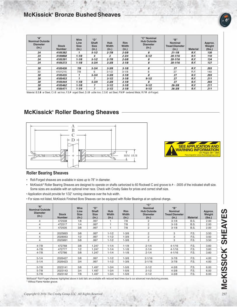
McKissick® Bronze Bushed Sheaves
Bronze Bushed Sheaves• Roll-Forged sheaves are available in sizes up to 78” in diameter.
• McKissick®
• For sizes not listed, McKissick Finished Bore Sheaves can be equipped with bronze bushings at an optional charge.
“A” Nominal Outside
Diameter (in.)
Stock Number
Wire Line Size (in.)
“D” Shaft Size (in.)
Hub
Width (in.)
Rim
Width (in.)
“C” Nominal Hub Outside
Diameter (in.)
“B”
Nominal Tread Diameter
(in.)
Material
Approx.Weight (lbs.)
2-1/4 907004 1/4 3/8* 5/8 9/16 3/4 1-7/8 B.S. .75
3 907059 3/16 3/8* 25/32 3/4 1 2-3/8 P.M. 1.00
3 907077 3/16 1/2* 25/32 3/4 1 2-3/8 P.M. 1.00
3 907095 3/16 5/8* 25/32 3/4 1 2-3/8 P.M. 1.00
3 907022 1/4 3/8* 1/2 1/2 1 2-5/8 P.M. .75
3 907040 1/4 1/2* 1/2 1/2 1 2-5/8 P.M. .75
3 460165 1/4 1/2* 1-5/16 1-3/16 1-1/8 2-1/16 B.S. 1.00
3 2030896 5/16 3/4 1 7/8 1-3/4 2-1/4 P.M. 1.50
3 907068 3/8 3/8* 3/4 3/4 1 2-3/8 P.M. 1.00
3 916101 3/8 3/8* 25/32 3/4 1-1/2 2-3/8 B.S. 1.00
3 907086 3/8 1/2* 3/4 3/4 1 2-3/8 P.M. 1.00
3 916110 3/8 1/2* 25/32 3/4 1-1/2 2-3/8 B.S. 1.00
3 460156 3/8 1/2* 1-5/16 1-3/16 1-1/8 2-1/16 B.S. 1.00
3 907102 3/8 5/8* 3/4 3/4 1 2-3/8 P.M. 1.00
3 2030895 3/8 3/4 1 7/8 1-3/4 2-1/4 P.M. 1.50
3 2023202 7/16 3/4 1 7/8 1-3/4 2-1/4 P.M. 1.50
3 916129 1/2 3/8* 1-1/4 1-1/8 1-7/8 2 B.S. 1.33
3 916138 1/2 1/2* 1-1/4 1-1/8 1-7/8 2 B.S. 1.50
4 460290 1/8 1 1 7/8 2 3-1/8 B.S. 2.00
4 907111 3/16 1/2* 3/4 5/8 1-3/8 3-1/2 P.M. 1.00
4 907139 3/16 5/8* 3/4 5/8 1-3/8 3-1/2 P.M. 1.00
4 916147 1/4 1/2* 13/16 3/4 2 3-1/4 B.S. 1.50
4 916165 1/4 3/4* 13/16 3/4 2 3-1/4 B.S. 1.50
4 460307 1/4 1 1 7/8 2 3-1/8 B.S. 2.00
4 907120 5/16 1/2* 3/4 5/8 1-3/8 3-1/2 P.M. 1.00
4 907148 5/16 5/8* 3/4 5/8 1-3/8 3-1/2 P.M. 1.00
4 907166 3/8 1/2* 13/16 3/4 1-1/2 3-1/4 P.M. 1.25
4 916156 3/8 1/2* 13/16 3/4 2 3-1/4 B.S. 1.50
4 907184 3/8 5/8* 13/16 3/4 1-1/2 3-1/4 P.M. 1.40
4 907200 3/8 3/4* 13/16 3/4 1-1/2 3-1/4 P.M. 1.25
4 460316 3/8 1 1 7/8 2 3-1/8 B.S. 2.00
4 907228 1/2 1/2* 1-1/16 1 1-5/8 3-3/16 P.M. 1.50
4 916192 1/2 1/2* 1-1/8 1 1-5/8 3-3/16 BS. 2.00
4 907246 1/2 5/8* 1-1/16 1 1-5/8 3-3/16 P.M. 1.50
4 907264 1/2 3/4* 1-1/16 1 1-5/8 3-3/16 P.M. 1.50
4 2028640 3/8 3/4* 13/16 3/4 2 3-1/4 B.S. 1.50
4-1/8 2023186 3/8 1 1-1/2 1-3/8 2 3 F.S. 3.50
4-1/8 2029618 1/2 1 1-1/2 1-3/8 2 3 F.S. 3.50
4-1/8 2023188 5/8 1 1-1/2 1-3/8 2 3 F.S. 3.50
4-1/4 460450 3/8 5/8* 1-3/16 15/16 2-1/8 3-3/8 B.S. 2.40
4-1/4 460441 1/2 5/8* 1-3/16 15/16 2-1/8 3-3/8 B.S. 2.40
4-3/4 460575 5/16 5/8 1-9/16 1-3/8 1-1/2 3-5/8 D.I. 3.50
4-3/4 460584 3/8 5/8 1-9/16 1-3/8 1-1/2 3-5/8 D.I. 3.50
4-3/4 460593 1/2 5/8 1-9/16 1-3/8 1-1/2 3-5/8 D.I. 3.50
*Self Lubricating Bushing. Custom sheaves are available. See page 287 for ordering details.
On Pages 381 - 388
SEE APPLICATION AND WARNING INFORMATION
Para Español: www.thecrosbygroup.com

Copyright © 2016 The Crosby Group LLC All Rights Reserved
McK
ISS
ICK
®
SH
EA
VE
S
294
McKissick® Bronze Bushed Sheaves
“A” Nominal Outside Diameter
(in.)Stock
Number
Wire Line Size (in.)
“D” Shaft Size (in.)
Hub
Width (in.)
Rim
Width (in.)
“C” Nominal
Hub Outside Diameter
(in.)
“B”
Nominal Tread Diameter
(in.)
Material
Approx.Weight (lbs.)
4-7/8 460478 3/8 1-1/4 1-1/4 1-1/8 2-1/4 4-1/16 F.S. 3.60
4-7/8 2026414 1/2 1-1/4 1-1/4 1-1/8 2-1/4 4-1/16 F.S. 3.60
4-7/8 460469 5/8 1-1/4 1-1/4 1-1/8 2-1/4 4-1/16 F.S. 3.60
5 907273 3/16 5/8* 15/16 7/8 2-1/4 4-1/4 P.M. 2.25
5 907291 3/16 3/4* 15/16 7/8 2-1/4 4-1/4 P.M. 2.25
5 460511 5/16 3/4 1 7/8 1-1/2 4 F.S. 2.50
5 907282 3/8 5/8* 15/16 7/8 2-1/4 4-1/4 P.M. 2.75
5 907308 3/8 3/4* 15/16 7/8 2-1/4 4-1/4 P.M. 2.80
5 460520 3/8 3/4 1 7/8 1-1/2 4 F.S. 2.50
5 460539 7/16 3/4 1 7/8 1-1/2 4 F.S. 2.50
5 907326 1/2 5/8* 1-1/16 1 2-1/4 4 P.M. 2.50
5 907362 1/2 5/8* 1-3/16 1-1/8 2-1/4 4 D.I. 4.00
5 907344 1/2 3/4* 1-1/16 1 2-1/4 4 P.M. 2.50
5 907380 1/2 3/4* 1-3/16 1-1/8 2-1/4 4 D.I. 4.00
5 907406 1/2 7/8* 1-3/16 1-1/8 2-1/4 4 D.I. 4.00
5-1/4 460628 5/8 1 1-1/2 1-3/8 2-1/16 3-7/8 F.S. 4.00
5-1/4 460637 3/4 1 1-1/2 1-3/8 2-1/16 3-7/8 F.S. 4.00
5-7/8 2023129 5/8 1-1/2 1-3/4 1-5/8 2-1/2 4-3/8 F.S. 6.00
5-7/8 2023137 3/4 1-1/2 1-3/4 1-5/8 2-1/2 4-3/8 F.S. 6.00
5-7/8 2023135 7/8 1-1/2 1-3/4 1-5/8 2-1/2 4-3/8 F.S. 6.00
6 907424 3/8 1/2* 13/16 3/4 1-7/8 5 P.M. 2.50
6 907488 3/8 1/2* 1-1/16 1 1-7/8 5 P.M. 2.50
6 907442 3/8 5/8* 13/16 3/4 1-7/8 5 P.M. 2.50
6 907503 3/8 5/8* 1-1/16 1 1-7/8 5 P.M. 2.50
6 907460 3/8 3/4* 13/16 3/4 1-7/8 5 P.M. 2.50
6 907521 3/8 3/4* 1-1/16 1 1-7/8 5 P.M. 4.26
6 2026483 3/8 3/4* 1-1/16 1 2 5-1/8 F.S. 4.00
6 916245 3/8 7/8* 1-1/16 1 2 5-1/8 F.S. 4.00
6 2028641 3/8 1* 1-1/16 1 2 5-1/8 F.S. 4.00
6 460682 3/8 1-1/4 1-1/8 1 2-1/4 4-15/16 F.S. 3.70
6 907549 1/2 5/8* 1-3/16 1-1/8 1-7/8 4-7/8 P.M. 5.00
6 907567 1/2 3/4* 1-3/16 1-1/8 1-7/8 4-7/8 P.M. 4.72
6 913024 1/2 7/8* 1-1/16 1 1-7/8 4-7/8 P.M. 3.75
6 460879 1/2 1 1-1/2 1-1/4 3-1/8 4-3/4 B.S. 7.00
6 460673 1/2 1-1/4* 1-1/8 1 2-1/4 4-15/16 F.S. 3.63
6 2028048 1/2 1 1-1/16 1 1-7/8 4-7/8 P.M. 3.75
6 2026938 5/8 3/4* 1-1/16 1 2 5-1/8 F.S. 4.00
6 913060 5/8 3/4* 1-5/16 1-1/4 1-7/8 4-3/4 P.M. 3.75
6 916254 5/8 7/8* 1-1/16 1 2 5-1/8 F.S. 4.00
6 913088 5/8 7/8* 1-5/16 1-1/4 1-7/8 4-3/4 P.M. 5.00
6 2026822 5/8 1* 1-1/16 1 2 5-1/8 F.S. 4.00
6 913104 5/8 1* 1-5/16 1-1/4 1-7/8 4-3/4 P.M. 3.75
6 2023264 5/8 2 2-5/16 2-3/16 3-1/8 4-1/4 F.S. 9.50
6 460897 3/4 1 1-1/2 1-1/4 3-1/2 4-3/4 B.S. 7.00
6 913168 3/4 1 1-9/16 1-1/2 1-7/8 4-5/8 P.M. 6.75
6 2023260 3/4 2 2-5/16 2-3/16 3-1/8 4-1/4 F.S. 9.50
6 2023262 7/8 2 2-5/16 2-3/16 3-1/2 4-1/4 F.S. 9.50
6-3/4 907692 1/4 3/4* 1-3/16 1-1/8 2 5-7/8 D.I. 5.00
6-3/4 907718 1/4 1* 1-3/16 1-1/8 2 5-7/8 D.I. 5.00
6-3/4 907709 3/8 3/4* 1-3/16 1-1/8 2 5-7/8 D.I. 5.00
6-3/4 907727 3/8 1* 1-3/16 1-1/8 2 5-7/8 D.I. 5.00
7 461020 1/4 1-1/2 1-3/8 3/4 2-3/8 6-1/4 B.S. 6.20
7 461039 3/8 1-1/2 1-3/8 3/4 2-3/8 6-1/4 B.S. 6.20
7 907629 1/2 3/4* 1-1/16 1 2 5-5/8 D.I. 4.25
7 907647 1/2 7/8* 1-1/16 1 2 5-5/8 D.I. 4.25
7-1/2 460986 5/8 1 1-1/2 1-3/8 2-1/16 6-5/16 F.S. 7.50
7-1/2 460977 3/4 1 1-1/2 1-3/8 2-1/16 6-5/16 F.S. 7.50
7-5/8 461262 3/8 1 1-1/2 1-1/4 2-3/8 6-3/16 D.I. 7.00
7-5/8 461280 1/2 1 1-1/2 1-1/4 2-3/8 6-3/16 D.I. 7.00
7-5/8 461271 5/8 1 1-1/2 1-1/4 2-3/8 6-3/16 D.I. 7.00
*Self Lubricating Bushing. Custom sheaves are available. See page 287 for ordering details.

McK
ISS
ICK
®
SH
EA
VE
S
Copyright © 2016 The Crosby Group LLC All Rights Reserved 295
McKissick® Bronze Bushed Sheaves
“A” Nominal Outside
Diameter (in.)
Stock Number
Wire Line Size (in.)
“D” Shaft Size (in.)
Hub
Width (in.)
Rim
Width (in.)
“C” Nominal Hub Outside
Diameter (in.)
“B”
Nominal Tread Diameter
(in.)
Material
Approx.Weight (lbs.)
8 2023467 1 2-1/4 2-1/2 2-3/8 4-1/2 5-3/8 F.S. 18.0
8 2023463 1-1/8 2-1/4 2-1/2 2-3/8 4-1/2 5-3/8 F.S. 18.0
8 2023153 3/4 1-1/2 1-3/4 1-5/8 2-9/16 6-5/16 F.S. 10.0
8 907745 1/2 3/4* 1-1/8 1 2-3/8 6-7/8 D.I. 5.00
8 916487 1/2 3/4* 1-3/8 1-1/4 2 6-5/8 F.S. 7.00
8 907763 1/2 7/8* 1-1/8 1 2-3/8 6-7/8 D.I. 5.00
8 916502 1/2 7/8* 1-3/8 1-1/4 2 6-5/8 F.S. 7.00
8 907781 1/2 1* 1-1/8 1 2-3/8 6-7/8 D.I. 5.59
8 916520 1/2 1* 1-3/8 1-1/4 2 6-5/8 F.S. 7.00
8 2026841 1/2 1-1/8* 1-3/8 1-1/4 2 6-5/8 F.S. 7.00
8 2026844 1/2 1-1/4* 1-3/8 1-1/4 2 6-5/8 F.S. 7.00
8 461235 1/2 1-1/2 1-1/2 1-3/8 2-7/16 6-5/8 F.S. 7.00
8 2023145 1/2 1-1/2 1-3/4 1-5/8 2-9/16 6-5/16 F.S. 10.0
8 907807 5/8 3/4* 1-3/8 1-1/4 2 6-1/2 D.I. 6.75
8 913300 5/8 7/8* 1-3/8 1-1/4 2-1/2 6-5/8 D.I. 8.50
8 913328 5/8 1* 1-3/8 1-1/4 2-3/4 6-5/8 D.I. 7.20
8 913346 5/8 1-1/8* 1-3/8 1-1/4 2-1/2 6-5/8 D.I. 8.50
8 913364 5/8 1-1/4* 1-3/8 1-1/4 2-1/2 6-5/8 D.I. 8.50
8 913382 5/8 1-1/2* 1-3/8 1-1/4 2-1/2 6-5/8 D.I. 8.50
8 461244 5/8 1-1/2 1-1/2 1-3/8 2-7/16 6-5/8 F.S. 7.00
8 2023147 5/8 1-1/2 1-3/4 1-5/8 2-9/16 6-5/16 F.S. 10.0
8 461253 3/4 1-1/2 1-1/2 1-3/8 2-7/16 6 F.S. 7.00
8 2028227 3/4 2 2-5/16 2-1/8 3-1/4 6-1/8 F.S. 12.5
8 461397 3/4 2-3/4 2-5/16 2-3/16 3-3/4 6 R.F. 10.5
8 2023386 7/8 2 2-5/16 2-1/8 3-1/4 6-1/8 F.S. 12.5
8 461501 1-1/8 3-1/2 2-1/2 2-3/8 5 5-7/16 C.S. 15.0
9-7/8 462831 3/8 2-1/2 1-3/4 1-1/8 3-3/4 8-9/16 F.S. 14.0
9-7/8 462154 1/2 1* 1-1/2 1-3/8 3-1/4 8-1/2 F.S. 9.50
9-7/8 2023166 1/2 1-1/2 1-3/4 1-5/8 2-9/16 8-5/16 F.S. 14.5
9-7/8 462840 1/2 2-1/2 1-3/4 1-1/8 3-3/4 8-9/16 F.S. 14.0
9-7/8 462163 5/8 1* 1-1/2 1-3/8 3-1/4 8-1/2 F.S. 9.50
9-7/8 2023170 5/8 1-1/2 1-3/4 1-5/8 2-9/16 8-5/16 F.S. 14.5
9-7/8 2023174 3/4 1-1/2 1-3/4 1-5/8 2-9/16 8-5/16 F.S. 14.5
9-7/8 2023420 7/8 2 2-5/16 2-3/16 3-1/2 8-1/8 F.S. 15.0
9-7/8 2023428 1 2 2-5/16 2-3/16 3-1/2 8-1/8 F.S. 15.0
10 2026861 1-1/8 2-1/4 2-1/2 2-3/8 4-1/2 7-3/8 F.S. 27.0
10 2023785 1-1/8 3-1/2 2-1/2 2-3/8 5-3/4 7-3/8 F.S. 28.0
10 907923 1/2 7/8* 1-1/8 1 2-7/8 8-3/4 D.I. 10.0
10 907941 1/2 1* 1-1/8 1 2-7/8 8-3/4 D.I. 11.8
10 907969 5/8 3/4* 1-3/8 1-1/4 2 8-1/2 D.I. 9.25
10 916717 5/8 7/8* 1-3/8 1-1/4 2-3/4 8-1/2 F.S. 10.0
10 913685 5/8 7/8* 1-3/8 1-1/4 3 8-1/2 D.I. 13.5
10 908003 5/8 1* 1-3/8 1-1/4 2 8-1/2 D.I. 9.25
10 916726 5/8 1* 1-3/8 1-1/4 2-3/4 8-1/2 F.S. 14.0
10 2027291 5/8 1-1/4* 1-3/8 1-1/4 2-3/4 8-1/2 F.S. 14.0
10 913765 5/8 1-1/2* 1-3/8 1-1/4 3 8-1/2 D.I. 12.6
10 913863 3/4 1-1/2* 1-5/8 1-1/2 3-1/2 8-1/4 F.S. 16.0
10 916824 3/4 1-1/4* 1-5/8 1-1/2 3-1/2 7-3/4 F.S. 17.0
10 913845 3/4 1-1/4* 1-5/8 1-1/2 3-1/2 8-1/4 F.S. 16.0
10 916833 3/4 1-1/2* 1-5/8 1-1/2 3-1/4 7-3/4 F.S. 17.0
10 913807 3/4 1* 1-5/8 1-1/2 3-1/2 8-1/4 F.S. 16.0
11-7/8 462323 3/8 2-1/2 2-5/16 1 3-3/4 10-3/4 D.I. 11.2
12 2023227 5/8 1-1/2 1-3/4 1-5/8 3-1/4 10-1/4 F.S. 22.0
12 2023235 3/4 1-1/2 1-3/4 1-5/8 3-1/4 9-3/8 F.S. 22.0
12 2023252 7/8 1-1/2 1-3/4 1-5/8 3-1/4 10-1/4 F.S. 22.0
12 462564 5/8 2-1/2 1-3/4 1-5/8 4-1/2 10-2/3 R.F. 24.012 462573 3/4 2-1/2 1-3/4 1-5/8 4-1/2 9-3/8 R.F. 24.012 908049 1/2 1* 1-1/8 1 4 10-5/8 D.I. 16.5
12 908085 1/2 1-1/4* 1-1/8 1 4 10-5/8 D.I. 16.5
12 917002 5/8 1* 1-5/8 1-1/2 3-1/4 10-1/8 F.S. 18.0
12 917011 5/8 1-1/8* 1-5/8 1-1/2 3-1/4 10-1/8 F.S. 18.0
12 462387 5/8 2 2-5/16 2-3/16 4-1/2 10-1/8 R.F. 26.012 908129 3/4 1* 1-5/8 1-1/2 2-3/4 10-1/4 D.I. 18.3
12 908147 3/4 1-1/8* 1-5/8 1-1/2 2-3/4 10-1/4 D.I. 18.3
12 914121 3/4 1-1/8* 1-5/8 1-1/2 5-1/4 10-1/4 D.I. 25.5
McKissick® Roll-Forged™ sheaves highlighted above in bold italic are available with reduced lead times due to our advanced manufacturing process. *Self-lubricating bushing.
Custom sheaves are available. See page 287 for ordering details.

Copyright © 2016 The Crosby Group LLC All Rights Reserved
McK
ISS
ICK
®
SH
EA
VE
S
296
McKissick® Bronze Bushed Sheaves
“A” Nominal Outside
Diameter (in.)
Stock Number
Wire Line Size (in.)
“D” Shaft Size (in.)
Hub
Width (in.)
Rim
Width (in.)
“C” Nominal Hub Outside
Diameter (in.)
“B”
Nominal Tread Diameter
(in.)
Material
Approx.Weight (lbs.)
12 914149 3/4 1-1/4 1-5/8 1-1/2 5-1/4 10-1/4 D.I. 25.5
12 914167 3/4 1-1/2* 1-5/8 1-1/2 5-1/4 10-1/4 D.I. 25.5
12 346593 3/4 2-1/4 2-5/16 2-3/16 4-1/2 9-3/4 R.F. 26.012 4104882 3/4 2-1/2 1-3/4 1-5/8 4-1/2 9-3/4 R.F. 25.012 462449 3/4 2 2-5/16 2-3/16 4-1/2 9-3/4 R.F. 26.012 4104917 3/4 2-1/2 2-5/16 2-3/16 4-1/2 9-3/4 R.F. 25.012 462485 3/4 3 3 1-7/8 5-1/2 9-3/8 R.F. 21.012 908227 7/8 1-1/4* 2 1-3/4 3-3/4 10 D.I. 20.3
12 908245 7/8 1-1/2* 2 1-3/4 3-3/4 10 D.I. 20.3
12 462458 7/8 2 2-5/16 2-3/16 4-1/2 10-1/4 R.F. 26.012 2023554 7/8 2-1/4 2-1/2 2-3/8 4-1/2 9-3/8 R.F. 28.012 4104891 7/8 2-1/2 1-3/4 1-5/8 4-1/2 10-1/4 R.F. 25.012 462467 1 2 2-5/16 2-3/16 4 10 R.F. 26.012 2023552 1-1/8 2-1/4 2-1/2 2-3/8 4-1/2 9-3/8 R.F. 26.0
13 462779 3/8 2 1-1/2 1-1/8 3-1/2 11-5/8 R.F. 14.013 462788 1/2 2 1-1/2 1-1/8 3-1/2 11-5/8 R.F. 14.014 463625 5/8 1-1/2 1-3/4 1-5/8 3-1/4 12-1/8 R.F. 20.014 463634 3/4 1-1/2 1-3/4 1-5/8 3-1/4 11-3/8 R.F. 20.014 463643 7/8 1-1/2 1-3/4 1-5/8 3-1/4 11-3/8 R.F. 20.014 463448 7/8 2-1/4 2-1/2 2-3/8 4-1/2 12-1/4 R.F. 28.014 463457 1 2-1/4 2-1/2 2-3/8 4-1/2 11-3/8 R.F. 28.014 463466 1-1/8 2-1/4 2-1/2 2-3/8 4-1/2 11-3/8 R.F. 28.014 **463518 1/2 3-3/4 2-1/2 1-3/8 5-1/16 12-5/8 R.F. 15.014 4103552 5/8 2 1-3/4 1-5/8 4-1/2 12-1/8 R.F. 29.214 **908281 3/4 1-1/8* 1-5/8 1-7/16 3-1/4 12-1/4 C.I. 26.5
14 **908307 3/4 1-1/4* 1-5/8 1-1/2 3-1/4 12-1/4 C.I. 26.5
14 917173 3/4 1-1/4* 1-5/8 1-1/2 4 12 R.F. 26.514 917191 3/4 1-1/2* 1-5/8 1-1/2 3-1/4 11-3/4 R.F. 26.514 4103632 3/4 2 1-3/4 1-5/8 4-1/2 11-3/4 R.F. 30.014 4104828 3/4 2-3/4 2-5/16 2-3/16 5-1/2 11-3/4 R.F. 35.014 917182 7/8 1-1/4* 1-5/8 1-1/2 4 12 R.F. 26.514 917208 7/8 1-1/2* 1-5/8 1-1/2 4 12 R.F. 26.514 463484 7/8 2 2-5/16 2-1/8 4-1/2 11-3/8 R.F. 28.014 4103641 7/8 2 1-3/4 1-5/8 4-1/2 12-1/4 R.F. 31.016 4101395 1/2 3-1/2 2-3/4 2-1/2 5-3/4 14-1/4 R.F. 54.016 4100047 3/4 3-1/2 2-3/4 2-1/2 5-3/4 13-3/8 R.F. 47.016 4100109 3/4 3-3/4 2-3/4 2-1/2 5-3/4 13-3/8 R.F. 42.016 4103703 7/8 2-1/2 2-5/16 2-3/16 4-1/2 12-15/16 R.F. 35.016 4105211 7/8 2-3/4 2-5/16 2-3/16 4-1/2 12-15/16 R.F. 42.016 917342 1 1-1/2* 2 1-3/4 4-1/4 13-1/4 R.F. 34.016 917360 1 2* 2 1-3/4 4-1/4 13-1/4 R.F. 34.016 4100127 1 3-3/4 2-3/4 2-1/2 5-3/4 13-1/4 R.F. 63.018 4105131 7/8 3 2-5/16 2-3/16 5-1/2 14-15/16 R.F. 52.018 4105195 7/8 5-1/2 2-7/8 2-5/8 8 14-15/16 R.F. 59.018 917468 1 1-1/2* 2 1-7/8 3-1/4 14-7/8 R.F. 55.018 917486 1 2* 2 1-7/8 4-1/2 14-7/8 R.F. 55.018 914826 1 2* 2 1-3/4 5-3/4 15-3/4 R.F. 62.018 4104052 1 2-3/4 2-5/16 2-3/16 5-1/2 14-7/8 R.F. 66.018 4105140 1 3 2-5/16 2-3/16 5-1/2 14-7/8 R.F. 52.018 4100298 1 4 3 2-3/4 6-1/2 15-1/8 R.F. 81.018 4103348 1-1/8 4 3 2-3/4 6-1/2 15-1/8 R.F. 60.020 4100341 3/4 3 2-5/16 2-3/16 5-1/2 18 R.F. 68.020 4105239 3/4 3-3/4 2-3/4 2-1/8 6-1/2 18 R.F. 68.020 4100350 7/8 3 2-5/16 2-3/16 5-1/2 17-1/8 R.F. 45.020 4105266 7/8 5-1/2 2-7/8 2-5/8 8 16-15/16 R.F. 68.020 4100369 1 3 2-5/16 2-3/16 5-1/2 17-1/8 R.F. 80.220 4105328 1 3-1/4 2-5/16 2-3/16 5-1/2 17-1/8 R.F. 68.020 4105257 1 3-3/4 2-3/4 2-1/8 6-1/2 16-1/2 R.F. 68.020 4105275 1 5-1/2 2-7/8 2-5/8 8 17-1/8 R.F. 68.024 4105346 9/16 5-3/4 3-3/8 3-1/8 8 22 R.F. 11324 4105355 7/8 5-3/4 3-3/8 3-1/8 8 21 R.F. 13324 4100859 1 4 3 2-3/4 9 21-1/8 R.F. 140.0
McKissick® Roll-Forged™ sheaves highlighted above in bold italic are available with reduced lead times due to our advanced manufacturing process.
* * Without Flame Harden groove.
*Self Lubricating Bushing.
McK
ISS
ICK
®
SH
EA
VE
S
Copyright © 2016 The Crosby Group LLC All Rights Reserved 297
McKissick® Bronze Bushed Sheaves
Roller Bearing Sheaves
• Roll-Forged sheaves are available in sizes up to 78” in diameter.
• McKissick® Roller Bearing Sheaves are designed to operate on shafts carborized to 60 Rockwell C and groove to +/ - .0005 of the indicated shaft size.
Some sizes are available with an optional inner race. Check with Crosby Sales for prices and correct shaft size.
• Application should provide for 1/32” running clearance over the hub width.
• For sizes not listed, McKissick Finished Bore Sheaves can be equipped with Roller Bearings at an optional charge.
“A” Nominal Outside
Diameter (in.)
Stock Number
Wire Line Size (in.)
“D” Shaft Size (in.)
Hub
Width (in.)
Rim
Width (in.)
“C” Nominal
Hub Outside Diameter
(in.)
“B”
Nominal Tread Diameter
(in.)
Material
Approx.Weight (lbs.)
4 472508 1/8 .997 1 7/8 2 3-1/8 B.S. 2.00
4 472517 1/4 .997 1 7/8 2 3-1/8 B.S. 2.00
4 472535 3/8 .997 1 7/8 2 3-1/8 B.S. 2.00
4 2025893 3/8 .997 1-1/2 1-3/8 2 3 F.S. 3.50
4 2028063 1/2 .997 1-1/2 1-3/8 2 3 F.S. 3.50
4 2025891 5/8 .997 1-1/2 1-3/8 2 3 F.S. 3.50
4-7/8 472768 3/8 1.247 1-1/4 1-1/8 2-1/4 4-1/16 F.S. 3.60
4-7/8 472777 1/2 1.247 1-1/4 1-1/8 2-1/4 4-1/16 F.S. 3.60
4-7/8 472786 5/8 1.247 1-1/4 1-1/8 2-1/4 4-1/16 F.S. 3.60
5-1/4 2026427 5/8 .997 1-1/2 1-3/8 2-1/16 3-7/8 F.S. 4.00
5-1/4 2026423 3/4 .997 1-1/2 1-3/8 2-1/16 3-7/8 F.S. 4.00
5-7/8 2023141 5/8 1.497 1-3/4 1-5/8 2-1/2 4-3/8 F.S. 6.00
5-7/8 2023143 3/4 1.497 1-3/4 1-5/8 2-1/2 4-3/8 F.S. 6.00
5-7/8 2023142 7/8 1.497 1-3/4 1-5/8 2-1/2 4-3/8 F.S. 6.00
“A” Nominal Outside
Diameter (in.)
Stock Number
Wire Line Size (in.)
“D” Shaft Size (in.)
Hub
Width (in.)
Rim
Width (in.)
“C” Nominal Hub Outside
Diameter (in.)
“B”
Nominal Tread Diameter
(in.)
Material
Approx.Weight (lbs.)
24 4105382 1 5-1/2 2-7/8 2-5/8 8 21-1/8 R.F. 13024 4100868 1-1/8 4 3 2-3/4 6-1/2 20-1/16 R.F. 11024 4105391 1-1/8 5-1/2 2-7/8 2-5/8 8 20-1/16 R.F. 13424 4105373 1-1/8 5-3/4 3-3/8 3-1/8 8 20-1/16 R.F. 13730 4105426 7/8 5-3/4 3-3/8 3-1/8 8 27 R.F. 20330 4101215 7/8 6 3-1/2 3-1/8 8 27 R.F. 140
30 4105435 1 5-3/4 3-3/8 3-1/8 8 27 R.F. 20330 4105453 1 7 3-1/2 3-1/8 9-1/2 27 R.F. 21130 4105444 1-1/8 5-3/4 3-3/8 3-1/8 8 27 R.F. 20330 4105462 1-1/8 7 3-1/2 3-1/8 9-1/2 26-3/8 R.F. 21130 4105471 1-1/4 7 3-1/2 3-1/8 9-1/2 26-3/8 R.F. 211
Material: B.S.=B ar Steel, C.I.=C ast Iron, F.S.=F orged Steel, D.I.=D uctile Iron, C.S.=C ast Steel, P.M.=P owdered Metal, R.F.=R oll-Forged.
McKissick® Roll-Forged sheaves highlighted above in bold italic are available with reduced lead times due to our advanced manufacturing process.
* Without Flame Harden groove.
McKissick® Roller Bearing Sheaves
On Pages 381 - 388
SEE APPLICATION AND WARNING INFORMATION
Para Español: www.thecrosbygroup.com

Copyright © 2016 The Crosby Group LLC All Rights Reserved
McK
ISS
ICK
®
SH
EA
VE
S
298
McKissick® Roller Bearing Sheaves
“A” Nominal Outside
Diameter (in.)
Pattern Number
Wire Line Size (in.)
“D” Shaft Size (in.)
Hub
Width (in.)
Rim
Width (in.)
“C” Nominal Hub Outside
Diameter (in.)
“B”
Nominal Tread Diameter
(in.)
Material
Approx.Weight (lbs.)
6 6-8 1/2 1.997 1-3/4 1-1/4 3-1/8 4-3/4 F.S. 7.00
7-1/2 8-7 5/8 .997 1-1/2 1-3/8 2-1/16 6-5/16 F.S. 7.50
7-1/2 8-7 3/4 .997 1-1/2 1-3/8 2-1/16 6-5/16 F.S. 7.50
7-5/8 8-10 3/8 .997 1-1/2 1-1/4 2-3/8 6-3/16 D.I. 7.00
7-5/8 8-10 1/2 .997 1-1/2 1-1/4 2-3/8 6-3/16 D.I. 7.00
7-5/8 8-10 5/8 .997 1-1/2 1-1/4 2-3/8 6-3/16 D.I. 7.00
8 8-2 3/4 1.497 1-3/4 1-5/8 2-9/16 6-5/16 F.S. 10.0
8 8-2 1/2 1.497 1-3/4 1-5/8 2-9/16 6-5/16 F.S. 10.0
8 8-2 5/8 1.497 1-3/4 1-5/8 2-9/16 6-5/16 F.S. 10.0
8 8NS-2 3/4 1.997 2-5/16 2-1/8 3-1/4 6-1/8 F.S. 12.5
9-7/8 10-2 1/2 1.497 1-3/4 1-5/8 2-9/16 8-5/16 F.S. 14.5
9-7/8 10-2 5/8 1.497 1-3/4 1-5/8 2-9/16 8-5/16 F.S. 14.5
9-7/8 10-2 3/4 1.497 1-3/4 1-5/8 2-9/16 8-5/16 F.S. 14.5
9-7/8 10NS-2 3/4 1.997 2-5/16 2-3/16 3-1/2 8-1/8 F.S. 15.0
12 12-1 5/8 1.497 1-3/4 1-5/8 3-1/4 10-1/8 F.S. 18.0
12 12-1 3/4 1.497 1-3/4 1-5/8 3-1/4 9-3/4 F.S. 18.0
12 12-1 7/8 1.497 1-3/4 1-5/8 3-1/4 10-1/4 F.S. 18.0
12 12-9 5/8 2.247 1-3/4 1-5/8 4-1/2 10-1/8 R.F. 16.012 12-9 3/4 2.247 1-3/4 1-5/8 4-1/2 9-3/4 R.F. 16.014 14-1 5/8 1.497 1-3/4 1-5/8 3-1/4 12 R.F. 20.014 14-1 3/4 1.497 1-3/4 1-5/8 3-1/4 11-3/4 R.F. 20.014 14-1 7/8 1.497 1-3/4 1-5/8 3-1/4 12-1/4 R.F. 20.014 14-2 5/8 1.997 1-3/4 1-5/8 4-1/2 12-1/8 R.F. 31.014 14-2 3/4 1.997 1-3/4 1-5/8 4-1/2 11-3/4 R.F. 31.016 16-5B 7/8 2.497 2-5/16 2-3/16 4-1/2 12-15/16 R.F. 48.018 18-2 7/8 2.747 2-5/16 2-3/16 5-1/2 14-15/16 R.F. 42.718 18-2 1 2.747 2-5/16 2-3/16 5-1/2 14-7/8 R.F. 66.020 20-2 1 2.997 2-5/16 2-3/16 5-1/2 16-1/2 R.F. 77.024 24-1A 1 2.247 2-1/2 2-3/8 5-1/2 21-1/8 R.F. 75.0
Material: B.S.=B ar Steel, C.I.=C ast Iron, F.S.=F orged Steel, D.I.=D uctile Iron, C.S.=C ast Steel, P.M.=P owdered Metal, R.F.=R oll-Forged.
McKissick® Roll-Forged sheaves highlighted above in bold italic are available with reduced lead times due to our advanced manufacturing process.
Custom sheaves are available. See page 287 for ordering details.

McK
ISS
ICK
®
SH
EA
VE
S
Copyright © 2016 The Crosby Group LLC All Rights Reserved 299
McKissick® Tapered Bearing Sheaves
Tapered Bearing Sheaves• Roll-Forged sheaves are available in sizes up to 78” in diameter.
• Tapered Bearing Sheaves are designed to operate on shafts machined to +/- .0005 of the indicated shaft size.
• Applications should provide for tightening separator plates against bearing cones to adjust and insure proper function of bearing.
• For sizes not listed, McKissick® Finished Bore Sheaves can be equipped with tapered bearing at an optional charge.
“A” Nominal Outside
Diameter (in.)
Stock Number
Wire Line Size (in.)
“D” Shaft Size (in.)
Hub
Width (in.)
Rim
Width (in.)
“C” Nominal Hub Outside
Diameter (in.)
“B”
Nominal Tread Diameter
(in.)
Material
Approx.Weight (lbs.)
4-7/8 480269 3/8 .749 1-3/8 1-1/8 2-1/4 4-1/16 F.S. 3.60
7 480777 1/4 .749 1-3/8 3/4 2-3/8 6-1/4 B.S. 9.00
8 481017 1/2 .749 1-3/8 1-1/4 2-7/16 6-5/8 F.S. 7.00
8-1/2 481044 3/8 .749 1-3/8 1 2-3/4 7-1/2 D.I. 7.50
9-3/4 481295 3/8 1.499 2-5/16 1 3-3/4 8-3/4 F.S. 11.20
11-7/8 481552 1/4 1.499 2-5/16 1 3-3/4 10-3/4 D.I. 12.0
12 481455 3/4 1.499 2-5/16 2-3/16 4-1/2 9-3/4 R.F. 24.012 481446 7/8 1.499 2-5/16 2-3/16 4-1/2 10-1/4 R.F. 24.016 4302793 1/2 1.998 2-15/16 2-1/2 5-3/4 14-1/4 R.F. 50.016 4300599 3/4 1.998 2-15/16 2-1/2 5-3/4 13-3/8 R.F. 55.016 4300018 7/8 1.499 2-5/16 2-3/16 4-1/2 12-15/16 R.F. 37.016 4300054 1 1.998 2-15/16 2-1/2 5-3/4 13-3/8 R.F. 42.018 4300081 3/4 1.998 2-15/16 2-3/16 6-1/2 16 R.F. 40.020 *4302524 5/16 1.998 2-15/16 1-3/8 5-3/4 18-7/8 R.F. 54.020 4300161 3/4 1.998 2-15/16 2-1/8 6-1/2 18 R.F. 87.020 4300189 1 1.998 2-15/16 2-1/8 6-1/2 16-1/2 R.F. 84.024 4301721 9/16 4.248 3-1/2 3-1/8 8 22 R.F. 12524 *4302720 5/8 2.755 2-15/16 1-1/2 6-1/2 21-3/4 R.F. 13624 4300312 7/8 4.248 3-1/2 3-1/8 8 20-7/8 R.F. 12524 4300321 1 4.248 3-1/2 3-1/8 7-5/8 21-1/8 R.F. 12524 4300401 1-1/8 2.755 2-15/16 2-3/4 6-1/2 20-1/16 R.F. 80.024 4300330 1-1/8 4.248 3-1/2 3-1/8 8 20-1/16 R.F. 12524 4300269 1-1/2 4.248 3-1/2 3-1/8 8-1/4 20 R.F. 12530 4300483 7/8 4.248 3-1/2 3-1/8 8 27 R.F. 14030 4300492 1 4.248 3-1/2 3-1/8 7-5/8 27 R.F. 21030 4300526 1 5.624 3-11/16 3-1/8 9-1/2 27 R.F. 19030 4300508 1-1/8 4.248 3-1/2 3-1/8 8 27 R.F. 14030 4300535 1-1/8 5.624 3-11/16 3-1/8 9-1/2 26-3/8 R.F. 14030 4300704 1-1/4 5.624 3-11/16 3-1/8 9-1/2 26-3/8 R.F. 140
* Without Flame Harden groove.
Material: B.S.=B ar Steel, C.I.=C ast Iron, F.S.=F orged Steel, D.I.=D uctile Iron, C.S.=C ast Steel, P.M.=P owdered Metal, R.F.=R ollForged.
McKissick® Roll-Forged sheaves highlighted above in bold italic are available with reduced lead times due to our advanced manufacturing process.
Custom sheaves are available. See page 287 for ordering details.
On Pages 381 - 388
SEE APPLICATION AND WARNING INFORMATION
Para Español: www.thecrosbygroup.com

Copyright © 2016 The Crosby Group LLC All Rights Reserved
McK
ISS
ICK
®
SH
EA
VE
S
300
Custom sheaves are available. See page 287 for ordering details.
“A” Nominal Outside
Diameter (in.)
Stock Number
Wire Line Size (in.)
Bore Information
Hub Width (in.)
Rim Width (in.)
“C” Nominal
Hub Outside
Diameter (in.)
“B” Nominal
Tread Diameter
(in.) Material
Approx.Weight (lbs.)
“D”Bore Size
(in.)
Bearing Info.(Bearing not Included)
Shaft Size (in.)
Bearing or EquivalentDescription
20” Sheave
20 2030311 9/16 4.722 2.756 NA-483-SW-472-D 2.750 2.750 6.500 17.62 R.F. 80
20 2029285 5/8 4.722 2.756 NA-483-SW-472-D 2.750 2.750 6.500 17.81 R.F. 75
24” Sheave
24 2030941 9/16 6.498 4.250 NA56425-SW-56650D 3.375 3.125 8.00 21.62 R.F. 103
24 2030905 5/8 6.498 4.250 NA56425-SW-56650D 3.375 3.000 8.00 22.00 R.F. 117
24 2026108 7/8 6.498 4.250 NA56425-SW-56650D 3.375 3.125 8.00 20.94 R.F. 128
24 2025931 1 6.498 4.250 NA56425-SW-56650D 3.375 3.125 9.00 21.12 R.F. 125
24” Crown Sheave**
24 2027885 9/16 6.498 4.250 NA56425-SW-56650D 3.375 3.125 8.00 21.62 R.F. 90
24 2027887 5/8 6.498 4.250 NA56425-SW-56650D 3.375 2.750 8.00 22.00 R.F. 80
24 2027880 7/8 6.498 4.250 NA56425-SW-56650D 3.375 3.125 8.00 20.94 R.F. 125
24 2023993 1 6.498 4.250 NA56425-SW-56650D 3.375 3.125 9.00 21.12 R.F. 110
30” Sheave
30 2026299 1 6.498 4.250 NA56425-SW-56650D 3.375 3.125 8.50 26.50 R.F. 190
30 2026036 1-1/8 6.498 4.250 NA56425-SW-56650D 3.375 3.125 9.00 26.06 R.F. 230
30 2026230 1 7.873 5.625 NA48685-SW/48620 3.500 3.125 10.25 26.50 R.F. 255
30 2026003 1-1/8 7.873 5.625 NA48685-SW/48620 3.500 3.125 10.25 26.06 R.F. 255
30 2030906 1 8.873 6.500 NA46790-SW-46720 3.625 3.375 10.25 26.50 R.F. 185
30 2030907 1-1/8 8.873 6.500 NA46790-SW-46720 3.625 3.375 12.00 26.06 R.F. 265
30” Crown Sheave**
30 2027941 1 6.498 4.250 NA56425-SW-56650D 3.375 3.125 9.00 26.50 R.F. 150
30 2027945 1-1/8 6.498 4.250 NA56425-SW-56650D 3.375 3.125 9.00 26.06 R.F. 200
30 2030274 1 7.873 5.625 NA48685-SW/48620 3.500 3.125 10.25 26.50 R.F. 161
30 2030260 1-1/8 7.873 5.625 NA48685-SW/48620 3.500 3.125 10.25 26.06 .R.F. 218
36” Sheave
36 2030942 1 7.873 5.625 NA48685-SW/48620 3.500 3.250 10.250 33.12 R.F. 350
36 2030908 1-1/8 7.873 5.625 NA48685-SW/48620 3.500 3.250 10.250 33.62 R.F. 350
36 2027967 1-1/4 7.873 5.625 NA48685-SW/48620 3.500 3.250 12.00 32.25 R.F. 320
36 2030943 1 8.873 6.500 NA46790-SW-46720 3.625 3.125 11.50 33.12 R.F. 353
36 2029390 1-1/8 8.873 6.500 NA46790-SW-46720 3.625 3.250 11.00 32.62 R.F. 300
36 2029392 1-1/4 8.873 6.500 NA46790-SW-46720 3.625 3.250 11.00 32.25 R.F. 300
36 2030944 1 10.873 8.000 LM241149NW/241110-D 3.625 3.125 14.00 33.12 R.F. 370
36 2030909 1-1/8 10.873 8.000 LM241149NW/241110-D 3.625 3.500 14.00 32.06 R.F. 358
36 2030945 1-1/4 10.873 8.000 LM241149NW/241110-D 3.625 3.375 14.00 32.25 R.F. 330
36” Crown Sheave**
36 2030282 1 7.873 5.625 NA48685-SW/48620 3.50 3.25 10.25 33.12 R.F 240
36 2030284 1 1/8 7.873 5.625 NA48685-SW/48620 3.50 3.25 10.25 32.62 R.F. 250
McKissick®
• Roll-Forged sheaves are available in sizes up to 78” in diameter.
• Applications should provide for tightening separator plates against bearing cones to adjust and insure proper function of bearing.
• Each sheave in the table below has a machined bore sized to accept the respective bearing number shown.
• The sheaves are provided from the factory plain bore (the bearings are not included).
** Crown Sheaves contain lightening holes.
McKissick® Standard API 8C Oilfield Sheaves
On Pages 381 - 388
SEE APPLICATION AND WARNING INFORMATION
Para Español: www.thecrosbygroup.com

McK
ISS
ICK
®
SH
EA
VE
S
Copyright © 2016 The Crosby Group LLC All Rights Reserved 301
Custom sheaves are available. See page 287 for ordering details.
“A” Nominal Outside
Diameter (in.)
Stock Number
Wire Line Size (in.)
Bore Information
Hub Width (in.)
Rim Width (in.)
“C” Nominal
Hub Outside
Diameter (in.)
“B” Nominal
Tread Diameter
(in.) Material
Approx.Weight (lbs.)
“D”Bore Size
(in.)
Bearing Info.(Bearing not Included)
Shaft Size (in.)
Bearing or EquivalentDescription
42” Sheave
42 2030946 1-1/8 8.873 6.500 NA46790-SW-46720 3.625 3.250 12.00 38.62 R.F. 460
42 2030947 1-1/4 8.873 6.500 NA46790-SW-46720 3.625 3.250 11.50 38.25 R.F. 470
42 2030948 1-1/8 10.873 8.000 LM241149NW/241110-D 3.625 3.250 14.00 38.62 R.F. 465
42 2030949 1-1/4 10.873 8.000 LM241149NW/241110-D 3.625 3.250 14.00 38.25 R.F. 460
42 2030950 1-1/8 12.873 9.250 NA8575SW-8520CD 4.500 3.500 16.00 38.62 R.F. 465
42 2030951 1-1/4 12.873 9.250 NA8575SW-8520CD 4.500 3.375 16.00 38.25 R.F. 475
44” Sheave
44 2030952 1-1/8 10.873 8.000 LM241149NW/241110-D 3.625 3.375 14.00 40.06 R.F. 615
44 2030953 1-1/4 10.873 8.000 LM241149NW/241110-D 3.625 3.000 14.00 40.25 R.F. 545
48” Sheave
48 2030954 1-1/8 10.873 8.000 LM241149NW/241110-D 3.625 3.250 14.00 44.62 R.F. 580
48 2030955 1-1/4 10.873 8.000 LM241149NW/241110-D 3.625 2.750 14.00 44.25 R.F. 512
48 2030956 1-1/4 13.686 9.999 LM249747NWLM249710D 3.875 3.250 17.00 44.25 R.F. 640
50” Sheave
50 2030938 1-1/4 10.873 8.000 LM241149NW/241110-D 3.625 3.375 14.00 46.25 R.F. 765
50 2030957 1-1/4 13.686 8.000 LM241149NW/241110-D 3.875 3.250 17.00 46.25 R.F. 765
50 2030958 1-3/8 13.686 9.999 LM249747NW/LM249710D 3.875 3.750 17.00 45.62 R.F. 735
55” Sheave
55 2030959 1-1/8 12.873 9.250 NA8575SW-8520CD 4.500 3.500 16.00 51.06 R.F. 890
55 2030960 1-1/4 12.873 9.250 NA8575SW-8520CD 4.500 3.375 16.00 51.25 R.F. 825
55 2030961 1-1/4 13.686 9.999 LM249747NW/LM249710D 3.875 3.500 19.00 51.25 R.F. 588
60” Sheave
60 2030879 1-1/4 13.686 9.999 LM249747NW/LM249710D 3.875 3.25 17.00 56.25 R.F. 1095
60 2030880 1-3/8 13.873 10.500 LM251649NW/251610-D 4.125 3.625 19.00 55.88 R.F. 1175
60 2030881 1-3/8 15.498 12.000 L357049NW/L357010D 4.125 3.75 19.00 55.88 R.F. 1175
60 2030875 1-1/2 13.686 9.999 LM249747NW/LM249710D 3.875 3.50 19.00 55.50 R.F. 1175
60 2030872 1-1/2 13.873 10.500 LM251649NW/251610-D 4.125 3.625 19.00 55.50 R.F. 1175
60 2030876 1-1/2 15.498 12.000 L357049NW/L357010D 4.125 3.50 19.00 55.50 R.F. 1165
60 2030877 1-5/8 15.498 12.000 L357049NW/L357010D 4.125 3.50 19.00 55.12 R.F. 1150
McKissick® Standard API 8C Oilfield Sheaves

Copyright © 2016 The Crosby Group LLC All Rights Reserved
McK
ISS
ICK
®
SH
EA
VE
S
302
McKissick® AISE Roll-Forged Sheaves
McKissick® manufactures special Roll-Forged Sheaves to meet the Specifications of AISE
Standard Number 6.
Iron and Steel Engineers for special use in electric overhead Traveling Cranes for Steel Mill Service.
• Other typical applications that may specify AISE sheaves:
• Mobile Cranes
• Portal Cranes
• Power Shovels
• Other equipment using Wirelinee
For additional information concerning special AISE sheaves, contact:
In U.S.A. - Crosby’s Special Engineered Product Group at 1-800-777-1555
In Canada - Crosby Canada at (905) 451-9261
In Europe - N.V. Crosby Europe at (+3 2) (0)15 75 71 25
Typical AISE Sheave Rim Profile withSpecified Dimensional Requirements
Sheave Wheel Contours
RopeDiameter*
(in.)
Dimensions(in.)
A B C D E F G
1/2 15 14-1/2 1-3/4 9/32 1/2 1/32 3/4
5/8 18-3/4 18-1/8 2 11/32 5/8 1/32 15/16
3/4 22-1/2 21-3/4 2-1/4 13/32 3/4 1/32 1-1/8
7/8 26-1/4 25-3/8 2-1/2 31/64 7/8 3/64 1-5/16
1 30 29 2-3/4 35/64 1 3/64 1-1/2
1-1/8 33-3/4 32-5/8 3 39/64 1-1/8 3/64 1-11/16
1-1/4 37-1/2 36-1/4 3-1/4 11/16 1-1/4 1/16 1-7/8
1-3/8 41-1/4 39-7/8 3-1/2 3/4 1-3/8 1/16 2-1/16
1-1/2 45 43-1/2 3-3/4 13/16 1-1/2 1/16 2-1/4
* Sheaves with other Wireline sizes are available upon request. Other pitch diameters available on application basis. Grooves are �ame hardened to min. RC35 for 1/2” Wireline and larger.

McK
ISS
ICK
®
SH
EA
VE
S
Copyright © 2016 The Crosby Group LLC All Rights Reserved 303
McKissick® European Style 45˚ Metric Sheaves
Wireline Size (mm)
Nominal Dimensions
(mm)
Groove Radius (mm)
Sheave O.D. (mm)
A B MIN MAX 280 300 320 350 400 450 500 520 550 600 630 650 700 800
11 40 19 5.83 6.05
12 40 18 6.36 6.60
13 40 18 6.89 7.15
11 40 19.5 5.38 6.05
12 40 20.5 6.36 6.60
13 40 19.5 6.89 7.15
14 40 21 7.42 7.70
15 40 21 7.95 8.25
16 45 25 8.48 8.80
17 45 25 9.01 9.35
13 40 23 6.89 7.15
14 40 22 7.42 7.70
15 40 22 7.95 8.25
15 45 25 7.95 8.25
16 45 24 8.48 8.80
17 45 24 9.01 9.35
15 45 26 7.95 8.25
16 45 25 8.48 8.80
17 50 28 9.01 9.35
18 50 27 9.54 9.90
19 55 28.5 10.07 10.45
20 55 25.5 10.60 11.00
21 60 34 11.13 11.55
22 60 33 11.66 12.10
23 60 33 12.19 12.65
19 55 31 10.07 10.45
20 55 30 10.60 11.00
21 55 30 11.13 11.55
21 60 34 11.13 11.55
22 60 33 11.66 12.10
23 60 33 12.19 12.65
21 60 34 11.13 11.55
22 60 33 11.66 12.10
23 60 33 12.19 12.65
23 65 37 12.19 12.65
24 65 36 12.72 13.20
25 65 36 13.25 13.75
26 70 39 13.78 14.30
27 70 39 14.31 14.85
23 65 37 12.19 12.65
24 65 36 12.72 13.20
25 65 36 13.25 13.75
26 70 39 13.78 14.30
27 75 43 14.31 14.85
28 75 42 14.84 15.40
29 75 42 15.37 15.95
27 75 43 14.31 14.85
28 75 43 14.84 15.40
29 75 42 15.37 15.95
28 80 47 14.84 15.40
29 80 46 15.37 15.95
30 80 45 15.90 16.50
32 80 45 16.96 17.60
30 90 50 15.90 16.50
32 90 48 16.96 17.60
34 90 48 18.02 18.70
34 100 56 18.02 18.70
36 100 54 19.08 19.80
38 100 54 20.14 20.90
Sheave O.D. / Wireline Information
Selecting your Sheave O.D. / Wireline Size Combinations
To ease the effort in choosing the proper standard McKissick® Roll-Forged sheave required for your application, we
standard Sheave O.D. / Wireline sizes that are available.
How to Read the Table
• Cells outlined in RED represent the standard O.D. / Wireline combinations available with
.

Copyright © 2016 The Crosby Group LLC All Rights Reserved
McK
ISS
ICK
®
SH
EA
VE
S
304
Western Block Sheaves
Block Size
Stock No.Manila
Rope Size(in.)
Sheave Size (in.)WeightEach(lbs.)
1101Galv.
1102Galv.
1103Galv.
OutsideDia.(A)
RimWidth
(B)
BoreSize(C)
3 900010 900216 900412 3/8 1-3/4 1/2 3/8 .25
4 900038 900234 900430 1/2 2-1/4 5/8 3/8 .75
5 900056 900252 900458 5/8 3 3/4 3/8 .50
6 900074 900270 900476 3/4 3-1/2 1 1/2 1.00
7 900092 900298 900494 7/8 4-1/4 1 1/2 1.25
8 900118 900314 900519 1 4-3/4 1-1/8 5/8 1.75
Block Size
Stock No.ManilaRope Size(in.)
Sheave Size (in.)Sleeve Diameter
(in.)WeightEach(lbs.)
1141Galv.
1142Galv.
1143Galv.
OutsideDia.
RimWidth
Bearing Diam.
(C)I.D.(F)
O.D.(E)
6 902018 902214 902410 3/4 3 1-1/8 3/4 1/2 3/4 1.00
7 902036 902232 902438 7/8 3-1/2 1-1/4 3/4 1/2 3/4 2.00
8 902054 902250 902456 1 4-1/2 1-3/8 7/8 5/8 7/8 3.00
10 902072 902278 902474 1-1/4 5-3/4 1-7/8 1 3/4 1 7.00
12 902090 902296 902492 1-1/2 6-3/4 2-1/8 1 3/4 1 12.0
Block Size
Stock No.Manila
Rope Size(in.)
Sheave Size (in.) Sleeve Diameter (in.)WeightEach(lbs.)
Bronze Bushed
Red
Bronze Bushed
Galv.Outside
Dia.Rim
Width
Bearing Diam.
(C)I.D.(F)
O.D.(E)
6 2027020 2027021 3/4 3 7/8 3/4 - - 1.30
8 2028971 2027015 1 4-1/8 1-3/8 1 - - 3.74
10 2028972 2026507 1-1/4 6 1-5/8 1-1/2 - - 10.00
12 2028973 2026509 1-1/2 8 1-5/8 1-1/2 - - 12.00
Block Size
Stock No.Manila
Rope Size(in.)
Sheave Size (in.) Sleeve Diameter (in.)WeightEach(lbs.)
Bronze Bushed
OutsideDia.
RimWidth
Bearing Diam.
(C)I.D.(F)
O.D.(E)
4 2028373 1/2 2-1/4 5/8 5/8 3/8 5/8 .75
6 2028375 3/4 3-1/2 1 3/4 1/2 3/4 1.00
8 2028376 1 4-3/4 1-1/8 7/8 5/8 7/8 1.75
Snatch Block Stock No.11921298WireLineSize
1293PaintedStockNo.
1293ManilaRopeSize
Sheave Size(in.)
Bush-ingI.D.
Sleeve Dimensions(in.)
Weight Each(lbs.)
StyleShell
Length1298
Painted1192
Painted
Out-sideDia.
HubWidth
RimWidth
BoreSize I.D. O.D. Length 1298 1192 1293
924 - 922005 - 5/8 - - 6 1-3/8 1-1/4 1-5/8 1-1/4 1 1-1/4 1-1/2 6.00 - -
924 - 922023 - 3/4 - - 8 1-5/8 1-1/2 1-7/8 1-1/2 1-1/4 1-1/2 1-3/4 11.0 - -
924 - 922041 - 7/8 - - 10 1-5/8 1-1/2 2-1/2 2 1-1/2 2 1-3/4 19.0 - -
924 - 922069 - 7/8 - - 12 2 1-3/4 2-1/2 2 1-1/2 2 2-1/8 22.0 - -940-941 - 922078 920579 3/8 - - 4 13/16 3/4 1-1/8 3/4 1/2 3/4 7/8 3.00 2.00 -
940-941 - 922087 920588 1/2 - - 6 1-1/16 1 1-3/8 1 3/4 1 1-1/8 7.00 3.84 -
940-941 - 922103 920604 5/8 - - 8 1-3/8 1-1/4 1-1/2 1-1/8 7/8 1-1/8 1-1/2 8.00 9.90 -
940-941 - 922121 920622 5/8 - - 10 1-3/8 1-1/4 1-5/8 1-1/4 1 1-1/4 1-1/2 12.0 17.0 -
940-941 - 922149 920640 3/4 - - 12 1-5/8 1-1/2 1-7/8 1-1/2 1-1/4 1-1/2 1-3/4 39.0 32.0 -
1096 6 - - 921505 7/8 3 1-3/16 1-1/8 1-3/8 1 5/8 1-1/4 1-1/2 - - 2.00
1096 8 - - - 921523 1 4-1/2 1-7/16 1-3/8 1-5/8 1-1/4 7/8 1-1/4 1-1/2 - - 6.00
961 - 922407 - 5/8 - 6 1-5/8 1-1/2 2 1-5/8 1-1/4 1-5/8 1-3/4 9.00 -
961 - 922425 - 7/8 - 8 1-11/16 1-1/2 2-1/2 2 - 15.0 - -
Western Block Sheaves
On Pages 381 - 388
SEE APPLICATION AND WARNING INFORMATION
Para Español: www.thecrosbygroup.com
Western Block Sheaves
IRON SHEAVES FOR USE WITH MANILA ROPE BLOCKS
• 1101 – 1141 Common Iron Bushed
• 1102 – 1142 Roller Bushed
• 1103 – 1143 Bronze Bushed, Self-Lubricating
FOR MANILA AND WIRE ROPE SNATCH BLOCKS – OLD STYLE• 1298 - Bronzed Brushed, Self-Lubricating Steel sheave for Wire Rope.• 1192 - Bronzed Brushed, Self-Lubricating Iron sheave for Wire Rope.• 1293 - Bronzed Brushed, Self-Lubricating Steel sheave for Manila Rope.
FOR REGULAR MANILA ROPE BLOCKS – OLD STYLE
FOR MANILA ROPE SNATCH BLOCKS – OLD STYLE
FOR MANILA ROPE SNATCH BLOCKS – NEW STYLE
FOR REGULAR MANILA ROPE BLOCKS – NEW STYLE
Sheaves highlighted above in bold italic are available with reduced lead times due to our advanced manufacturing process.


![918 todd[1]](https://static.fdocuments.in/doc/165x107/55d713f6bb61eb81548b46c7/918-todd1.jpg)