

제4차 산업혁명을 선도하는 ICT Innovator - ETRI · 2017-03-06 · “etri 40년! 제4차 산업혁명의 견인차로 자리매김할 것” 발간사 1976년 설립된

2016. 11. 15.
Taeheum Na : {[email protected]}
Network SW Platform Research Section
ETRI
Optimal Service Placement using
Pseudo Service Chaining Mechanism
[Playnet-MANO]
IETF 97 meeting @ Seoul
Contents
Background
• Playnet-MANO
PSCM : Pseudo Service Chaining Mechanism
• Phase 1: Calculation of virtual link cost
• Phase 2: Selection of available computing nodes
• Phase 3: Greedy placement
Conclusion
- 1 -

- 2 -
Playnet-MANO

Playnet-MANO
Playnet-MANO = Playground for virtualized network application
• Open Source MANO (OSM) based NFV Environment
• Extended VIM functionality: OpenStack (liberty)
Container and KVM based virtualization
Using Nova-docker plugin
Consideration for point-to-point link (E-line type)
• Saving & loading Network Service (NS)
Save and load NS using VNFFG format
NFVI
(Openstack)
VIM
(Openstack)Openstack
API
VIM API
VIM
Function
VIM
VNFM NFVO
UI/UX
VNF
EM
VNF
EM
Link
Server
- 3 -
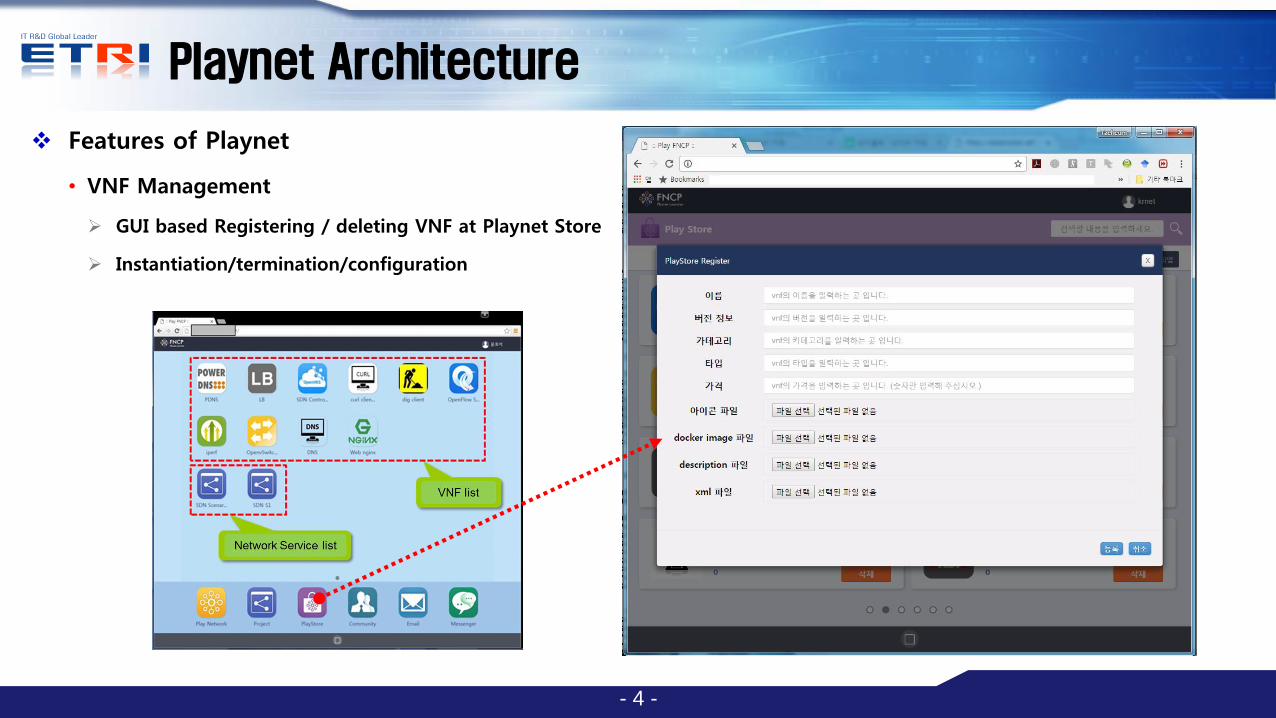
Playnet Architecture
Features of Playnet
• VNF Management
GUI based Registering / deleting VNF at Playnet Store
Instantiation/termination/configuration
- 4 -

Playnet Architecture
Features of Playnet
• Network Service Management
Network Services are managed as projects
Project save configuration for VNFs are also saved
Loading the project all VNF instances are activated
Configurations for VNFs are also synchronized
Project termination all VNF instances are terminated
• Creating/deleting link among VNFs
Point-to-Point, Multipoint-to-Multipoint
• Flavor management
• When NS is loaded, need to consider optimal
placement for the link performance
- 5 -
canvas
Stencil
tool

Related work
IETF Standard
• draft-irtf-nfvrg-resource-management-service-chain-03
• draft-lee-sfc-dynamic-instantiation-01
• Both draft document mention traffic localization
Our work can be one of the use case
ETSI Standard
• VNFFG Descriptor (VNFFGD)
• Virtual Link Descriptor (VLD)
Throughput/Bandwidth requirement, QoS
• Virtual Link Record (VLR)
Allocated_capacity
need more specific parameter for the link
number of transaction (VLD), weight of transaction (VLD), amount of transmitted data (VLR)
- 6 -

- 7 -
Pseudo Service Chaining Mechanism

Pseudo Service Chaining Mechanism
Goal
• By localizing SFs (=Minimize the number of entity in SFPs) based on link description metric
• Saving core network bandwidth
• By avoiding capsulation, save the computation resource
• Getting more better performance of virtual link
Assumption
• Doesn't consider scaling, failover and policy
• Metric of Link parameter is decided by Operator (SFC user) at first
• Based on monitoring, it can be updated
- 8 -

Pseudo Service Chaining Mechanism
Overview of mechanism
- 9 -
• Phase 1: Calculation of Virtual Link Costs
Based on VLD parameters calculate link cost
Selecting pseudo virtual node (PVN)
• Phase 3: Placement PVN
• Phase 2: selection of available computing
nodes
• It is recursively conducted

Pseudo Service Chaining Mechanism
Phase 1: Calculation of Virtual Link Costs
• Transaction among service nodes
• Transaction weight at virtual link
• Volume of traffic at virtual link
- 10 -
Table 1. Parameter definitions for calculation of virtual link costs.
Notation Definition
Amount of transactions at a virtual link i
Transaction weight for a virtual link i
Volume of traffic at a virtual link i
Cost of a virtual link i
List of virtual links in the order of cost
𝑐𝑖 = 𝑤𝑖 × 𝑁𝑅𝑂𝑀(𝑡𝑖)× 𝑏𝑖where, 0 < I < number of virtual link

Pseudo Service Chaining Mechanism
Phase 2: Selection of available computing nodes
• Based on resource requirement of instance
• Available compute node
1st available compute node
Available resource > resource requirement of PVN
2nd available compute node
Available resource > minimum resource requirement of SN
• Sort in descending order
- 11 -

Pseudo Service Chaining Mechanism
Phase 3: Greedy placement
• Multiple-Knapsack Problem
𝑦𝑖𝑘 1, 𝑖𝑓 𝑝𝑣𝑚𝑘 𝑖𝑠 𝑎𝑠𝑠𝑖𝑔𝑛𝑒𝑑 𝑖𝑛 𝐴𝑁𝑖
0, 𝑜𝑡ℎ𝑒𝑟𝑤𝑖𝑠𝑒 (8)
𝑚𝑎𝑥𝑖𝑚𝑖𝑧𝑒𝑠 𝑧 = 𝑝𝑤𝑘𝑦𝑖𝑘𝑛𝑗 =1
𝑚𝑖=1 (9)
𝑥𝑗𝑘 1, 𝑖𝑓 𝑣𝑚𝑗 𝑖𝑠 𝑎𝑠𝑠𝑖𝑔𝑛𝑒𝑑 𝑖𝑛 𝑝𝑣𝑚𝑘
0, 𝑜𝑡ℎ𝑒𝑟𝑤𝑖𝑠𝑒 (5)
𝑉𝑟𝑗𝑥𝑗𝑘𝑛𝑗=1 < 𝑅𝑖 (6)
𝑝𝑤𝑘 = 𝑤𝑗𝑥𝑗𝑘𝑛𝑗=1 (7)
- 12 -

Pseudo Service Chaining Mechanism
Phase 3: Greedy placement
• Maximize the sum of cost in the allocated PVM
𝑨𝑵𝟏
𝑨𝑹𝟏
𝑨𝑵𝟐
𝑨𝑹𝟐 𝑨𝑵𝟑
𝑨𝑹𝟑
𝑺𝑵𝟏
𝑹𝟏
𝑺𝑵𝟑
𝑹𝟑
𝑺𝑵𝟐
𝑹𝟐
𝑺𝑵𝟒
𝑹𝟒
𝒕𝟑𝒕𝟐𝒕𝟏𝒕𝟐> 𝒕𝟏> 𝒕𝟑
𝑨𝑵𝟏
𝑨𝑹𝟏
𝑨𝑵𝟑
𝑨𝑹𝟑
𝑺𝑵𝟏
𝑹𝟏
𝑺𝑵𝟒
𝑹𝟒
𝒕𝟐> 𝒕𝟏> 𝒕𝟑
𝒊𝒇, 𝑨𝑹𝟐> 𝑹𝟐 +𝑹𝟑
𝑨𝑹𝟐< 𝑹𝟏 + 𝑹𝟐 +𝑹𝟑
𝑨𝑹𝟐> 𝑨𝑹𝟏> 𝑨𝑹𝟑
𝑨𝑹𝟐> 𝑨𝑹𝟏> 𝑨𝑹𝟑
𝑷𝑽𝑵𝟏
𝑹𝟐 +𝑹𝟑
𝒎𝒂𝒙( 𝒕𝟏, 𝒕𝟑)= 𝒕𝟏
𝑨𝑵𝟐
𝑨𝑹𝟐−(𝑹𝟐+𝑹𝟑)
𝑨𝑵𝟏
𝑨𝑹𝟏
𝑨𝑵𝟐
𝑨𝑹𝟐 𝑨𝑵𝟑
𝑨𝑹𝟑
𝑺𝑵𝟏
𝑹𝟏
𝑺𝑵𝟒
𝑹𝟒
𝒕𝟑𝒕𝟏
𝒕𝟐> 𝒕𝟏> 𝒕𝟑
𝑷𝑽𝑵𝟏
𝑹𝟐 +𝑹𝟑
𝒊𝒇, 𝑨𝑹𝟐> 𝑹𝟐 +𝑹𝟑
𝑨𝑹𝟐> 𝑨𝑹𝟏> 𝑨𝑹𝟑

Conclusion
Result
• improvement of 14% in RTT
• improvement of 37% in UDP receive rate
Analysis
• Better performance for Loss-rate of UDP
• Decrease round trip time
• Less CPU usage of host node(Interrupt)
- 14 -