R d = s icd-10-cm to icd-9-cm cross reference whitebook-sample 1

Standard Specifications For Public W
orks Construction 2015 Edition
THE “W
HITEBO
OK” |
|
THE“WHITEBOOK”
Public Works Department
Standard Specifications For Public Works Construction
2015 EditionPROJECT IMPLEMENTATION DIVISION STANDARDS & CONTRACT DOCUMENTS SECTION525 B STREET STE. 750 SAN DIEGO, CA 92101
DOCUMENT NUMBER: PWPI070116-02
2015 The White Book Cover.indd 1 2/16/16 12:02 PM

City Supplement (Rev. 2015) i THE “WHITEBOOK”
THE “WHITEBOOK”
Standard Specifications For Public Works Construction
2015 Edition
Written as a City of San Diego Supplement to the 2015 Greenbook by
the Public Works Department, Project Implementation Division,
Standards & Contract Documents Section.

City Supplement (Rev. 2015) ii THE “WHITEBOOK”
INTRODUCTION This edition of the City of San Diego Standard Specifications for Public Works Construction (“The WHITEBOOK”) contains the following standard Contract Documents:
1. CITY SUPPLEMENTS. Use the City Supplements in conjunction with the Standard Specifications for Public Works Construction (“The GREENBOOK”), 2015 Edition (http://www.greenbookspecs.org/).
To address the special conditions of alternative contracting methods, the City Supplements, Part 1, General Provisions, has been divided as follows:
General Provisions (A). These provisions apply to all contracts.
General Provisions (B). When applicable, these additional provisions to General Provisions (A) apply to the alternative project contracting method “Job Order Contracting” (JOC) only.
General Provisions (C). When applicable, these additional provisions to General Provisions (A) apply to the alternative project contracting methods “Design-Build” (DB) and “Multiple Award Construction Contract” (MACC) only.
2. EQUAL OPPORTUNITY CONTRACTING PROGRAM REQUIREMENTS. This Contract Document sets forth the standard requirements for the City’s Equal Opportunity Contracting Program.
Note: Parts of these specifications have been highlighted for the user’s convenience and may require extrinsic action for its use.
STYLE OF SPECIFICATIONS
The City has standardized the style and language of the Standard Specifications for Public Works Construction. The new style and language follows the Federal guidelines for “Plain Language” (http://www.plainlanguage.gov/) to the extent possible. Therefore, when used in the Contract Documents, statement or command phrases (active voice and imperative mood) refer to and are directed at the “Bidder” or “Contractor” as applicable. The specifications are written to the “Bidder” before award and the “Contractor” after award. Before award, interpret sentences written in the imperative mood as starting with “The Bidder shall”. Additionally, interpret the term “you” as “the Bidder” and interpret the term “your” as “the Bidder’s”. After award, interpret sentences written in the imperative mood starting with “The Contractor shall”. Additionally, interpret the term “you” as “the Contractor” and interpret the term “your” as “the Contractor’s.

City Supplement (Rev. 2015) iii THE “WHITEBOOK”
DOCUMENT AVAILABILITY AND COMMENTS
An electronic copy of The WHITEBOOK is available for download from the City’s web site:
http://www.sandiego.gov/publicworks/edocref/greenbook.shtml
The City of San Diego is committed to the quality of this publication and desires to correct any errors, omissions, or ambiguities. If you have any suggestions, comments, corrections, or additions, you may submit them to: [email protected].
ACKNOWLEDGEMENT
The continuous contribution and support in standardizing and updating these specifications of the following members and subject matter experts of the Whitebook 2015 Committee are acknowledged:
CITY ATTORNEY Mark Mercer
DEVELOPMENT SERVICES Alireza Sabouri, Crystal Cliame, and Nicholas Abboud
ENVIRONMENTAL SERVICES Joy Newman, Lorie Cosio-Azar, and George Katsikaris
PUBLIC UTILITIES Ernesto Fernandez and Paul Buehler
PUBLIC WORKS Ahmed Aburahmah, Alaine James, Angelita Jaro, Julie Ballesteros, Berric Doringo, Bill Swallow, Carrie Purcell, Casey Crown, Catherine Dungca, Christopher Naval, Corson Smith, David Li, Dino Ciafre-Garay, Dwayne Abbey, Fernando Lasaga, Fletcher Callanta, Frank Gaines, Harry Nguyen, Hudson McLintock, Jerry Borja, Jose Navarro, Katherine Santos, Kevin Cook, Kevin Oliver, Luis Schaar, Mark Calleran, Michael Ninh, Nibras Romaya, Nikki Lewis, Randy Encinas, Ramesis Bustamante, Sadegh Jahadi, Sarah Chavez, Sheila Bose, Stephen Samara, Todd Schmidt, Tony Perez, and Wendy Gamboa
PURCHASING & CONTRACTING Claudia Abarca and Henry Foster
RISK MANAGEMENT Claudia CastilloDelMuro
TRANSPORTATION & STORM WATER Brian Genovese, Chris Gascon, Duncan Hughes, Eddie Flores, Sumer Hasenin, and Jonard
Talamayan

City Supplement (Rev. 2015) iv THE “WHITEBOOK”
TABLE OF CONTENTS
PART 1 – GENERAL PROVISIONS GENERAL PROVISIONS (A)
SECTION 1 - TERMS, DEFINITIONS, ABBREVIATIONS, UNITS OF MEASURE, AND SYMBOLS ......... 1
SECTION 2 - SCOPE AND CONTROL OF WORK ....................................................................... 11
SECTION 3 - CHANGES IN WORK ............................................................................................. 31
SECTION 4 - CONTROL OF MATERIALS ................................................................................... 39
SECTION 5 - UTILITIES .............................................................................................................. 45
SECTION 6 - PROSECUTION, PROGRESS, AND ACCEPTANCE OF THE WORK ....................... 47
SECTION 7 - RESPONSIBILITIES OF THE CONTRACTOR ......................................................... 70
SECTION 8 - FACILITIES FOR AGENCY PERSONNEL ............................................................. 147
SECTION 9 - MEASUREMENT AND PAYMENT ....................................................................... 150
GENERAL PROVISIONS (B) - JOB ORDER CONTRACTING (JOC) ONLY
SECTION 1 - TERMS, DEFINITIONS, ABBREVIATIONS, UNITS OF MEASURE, AND SYMBOLS ................................................................................................... 160
SECTION 2 - SCOPE AND CONTROL OF WORK ..................................................................... 162
SECTION 3 - CHANGES IN WORK ........................................................................................... 166
SECTION 6 - PROSECUTION, PROGRESS, AND ACCEPTANCE OF THE WORK ..................... 167
SECTION 7 - RESPONSIBILITIES OF THE CONTRACTOR ...................................................... 168
GENERAL PROVISIONS (C) - DESIGN-BUILD (DB) AND MULTIPLE AWARD CONSTRUCTION CONTRACT (MACC) CONTRACTING ONLY
SECTION 1 - TERMS, DEFINITIONS, ABBREVIATIONS, UNITS OF MEASURE, AND SYMBOLS ................................................................................................... 169
SECTION 2 - SCOPE AND CONTROL OF WORK ..................................................................... 171
SECTION 3 - CHANGES IN WORK ........................................................................................... 179
SECTION 4 - CONTROL OF MATERIALS ................................................................................. 181
SECTION 5 - UTILITIES ............................................................................................................ 182
SECTION 6 - PROSECUTION, PROGRESS, AND ACCEPTANCE OF THE WORK ..................... 183
SECTION 7 - RESPONSIBILITIES OF THE CONTRACTOR ....................................................... 184
SECTION 9 - MEASUREMENT AND PAYMENT ....................................................................... 187
SECTION 10 - GREEN BUILDINGS AND STORM WATER MANAGEMENT ............................. 188

City Supplement (Rev. 2015) v THE “WHITEBOOK”
PART 2 – CONSTRUCTION MATERIALS
SECTION 200 - ROCK MATERIALS .......................................................................................... 189
SECTION 201 - CONCRETE, MORTAR, AND RELATED MATERIALS ...................................... 195
SECTION 202 - MASONRY MATERIALS .................................................................................. 199
SECTION 203 - BITUMINOUS MATERIALS ............................................................................. 200
SECTION 206 - MISCELLANEOUS METAL ITEMS ................................................................... 209
SECTION 207 - GRAVITY PIPE ................................................................................................ 210
SECTION 209 - PRESSURE PIPE .............................................................................................. 216
SECTION 210 - PAINT AND PROTECTIVE COATINGS ............................................................ 226
SECTION 211 - MATERIAL TESTS ........................................................................................... 227
SECTION 212 - WATER AND SEWER SYSTEM VALVES AND APPURTENANCES .......................... 228
SECTION 213 - ENGINEERING GEOSYNTHETICS ................................................................... 234
SECTION 215 - PRIVATE SEWER PUMPS ................................................................................ 238
SECTION 218 - DETECTABLE WARNING TILES (DWT) ........................................................... 239
PART 3 – CONSTRUCTION METHODS
SECTION 300 - EARTHWORK .................................................................................................. 240
SECTION 301 - TREATED SOIL, SUBGRADE PREPARATIOND PLACEMENT OF BASE MATERIALS .......................................................................................... 246
SECTION 302 - ROADWAY SURFACING ................................................................................. 253
SECTION 303 - CONCRETE AND MASONRY CONSTRUCTION .............................................. 275
SECTION 304 - METAL FABRICATION AND CONSTRUCTION .............................................. 283
SECTION 306 - OPEN TRENCH CONDUIT CONSTRUCTION ................................................. 284
SECTION 307 - JACKING AND TUNNELING ........................................................................... 323
SECTION 308 - MICROTUNNELING ....................................................................................... 324
SECTION 309 - MONUMENTS ................................................................................................ 325
SECTION 314 - TRAFFIC STRIPING CURB AND PAVEMENT MARKINGS AND PAVEMENT MARKERS .......................................................................... 326
SECTION 315 - HORIZONTAL DIRECTIONAL DRILLING ....................................................... 327
SECTION 316 - PIPE BURSTING .............................................................................................. 334
SECTION 317 - PIPE FUSION .................................................................................................. 337

City Supplement (Rev. 2015) vi THE “WHITEBOOK”
PART 4 (NOT USED) – CONTROL OF MATERIALS
PART 5 – PIPELINE SYSTEM REHABILITATION
SECTION 500 - PIPELINE, MANHOLE, AND STRUCTURE REHABILITATION ........................ 346
PART 6 – TEMPORARY TRAFFIC CONTROL
SECTION 600 - ACCESS ........................................................................................................... 368
SECTION 601 - TEMPORARY TRAFFIC CONTROL FOR CONSTRUCTION AND MAINTENANCE WORK ZONES ..................................................................... 372
PART 7 – STREET LIGHTING AND TRAFFIC SIGNAL SYSTEMS
SECTION 700 - MATERIALS .................................................................................................... 386
SECTION 701 - CONSTRUCTION ............................................................................................ 440
PART 8 – LANDSCAPING AND IRRIGATION
SECTION 800 - MATERIALS .................................................................................................... 444
SECTION 801 - INSTALLATION .............................................................................................. 464
SECTION 802 - NATIVE HABITAT PROTECTION, INSTALLATION, MAINTENANCE, AND MONITORING ........................................................... 481
PART 9 – WATER WORKS
SECTION 900 - MATERIALS .................................................................................................... 493
SECTION 901 - INSTALLATION AND CONNECTION ............................................................. 504
PART 10 – EQUAL OPPORTUNITY CONTRACTING PROGRAM (EOCP)
SECTION A - GENERAL REQUIREMENTS ............................................................................... 518
SECTION B - SLBE-ELBE SUBCONTRACTING REQUIREMENTS ............................................. 527
INDEX ............................................................................................................................... 535

City Supplement (Rev. 2015) Page 1 THE “WHITEBOOK”
PART 1
GENERAL PROVISIONS (A)
SECTION 1 - TERMS, DEFINITIONS, ABBREVIATIONS, UNITS OF MEASURE, AND SYMBOLS
1-1 GENERAL. ADD the following:
1. The word “provide” shall mean “furnish and install”, unless otherwise stated.
1-2 TERMS AND DEFINITIONS. DELETE in its entirety and SUBSTITUTE with the following:
1. Agency - The City of San Diego.
2. Agreed Price - The cost for new or unforeseen Work, or for adjustments in the Contract Unit Price for changes in the character of the Work as specified in 3-2.4, “Agreed Prices”, established by mutual agreement between you and the City.
3. Agreement - See Contract.
4. Allowance (AL) - Payment under Allowance Bid items, denoted as “AL”, shall be based on the actual expenditures and for pre-authorized items of the Work in accordance with the Contract Documents. The unused portions of the Allowances shall revert to the City upon Acceptance of the Project.
5. Apparent Low Bidder - The Bidder whose Bid having been publicly opened, initially meets the material requirements of the Bid Documents and whose Bid price is the lowest received.
6. Applicable Laws - Laws, statutes, ordinances, rules, orders, and regulations of governmental authorities and courts having jurisdiction over the Project.
7. As-Builts - The CADD drawings prepared from the approved Red-lines for record keeping purposes.
8. Award of Contract (Award) - The date on which the Mayor or designee executes the Contract.
9. Assessment Act Contract - A Contract financed by special assessments authorized under a State Act or procedural ordinance of a City or County.
10. Base - A layer of specified material of planned thickness placed immediately below the pavement or surfacing.
11. Bid - The offer or proposal of the Bidder submitted on the prescribed form setting forth the prices for the Work.
12. Bidder - Any individual, firm, partnership, corporation, or combination thereof, submitting a Bid for the Work, acting directly or through a duly authorized representative.
13. Board - The officer or body constituting the awarding authority of the City.

City Supplement (Rev. 2015) Page 2 THE “WHITEBOOK”
14. Bond - Bid, performance, payment bond, or other instrument of security.
15. Business Day - See Working Day.
16. Calendar Day - See Days.
17. Caltrans - The State of California Department of Transportation.
18. Cash Contract - A Contract financed by means other than special assessments.
19. Certificate of Compliance - A written document signed and submitted by a supplier or manufacturer that certifies that the material or assembled material supplied to the Work site conforms to the requirements of the Contract Documents.
20. Change Order - An amendment to the agreement signed by the City authorizing an addition, deletion, or revision in the Work or an adjustment in the Contract Price or the Contract time issued after the effective date of the Contract. A Change Order may or may not also be signed by you.
21. City - The City of San Diego. See also Agency.
22. City Forces - The City’s employees who perform construction work.
23. City Supplement - the City of San Diego Standard Specifications for Public Works Construction, the “WHITEBOOK”.
24. Code - Refer to the statutes of the State of California.
25. Contract - The written agreement between the City and you that covers the Work.
26. Contract Documents - Contract Documents include the following: The signed Agreement, Addenda, Notice Inviting Bids, funding agency provisions, Bid and documentation accompanying the Bid and any post-bid documentation submitted prior to the Notice of Award when attached as an exhibit to the Contract, Bonds, Permits, CEQA documents, Supplementary Special Provisions (SSP), City’s EOCP Requirements, Standard Specifications (the “GREENBOOK”), City Supplement (the “WHITEBOOK”), Plans, Standard Drawings, Construction Documents, Reference Specifications listed in the Notice Inviting Bids, and Change Orders. Contract Documents, when applicable, shall also include: Site and Coastal development permits, NEPA documents, revegetation plans, biological letters or technical reports, habitat mitigation plans, storm water documents, and local, state, and federal resource agency permits.
27. Contractor - The individual, partnership, corporation, joint venture, or other legal entity having a Contract with the City to perform the Work. In the case of Work being done under a permit issued by the City, the Contractor shall also be construed as the permittee.
28. Contract Price - The total amount of money for which the Contract is awarded.
29. Contract Unit Price - The amount stated in the Bid for a single unit of an item of Work.
City Supplement (Rev. 2015) Page 3 THE “WHITEBOOK”
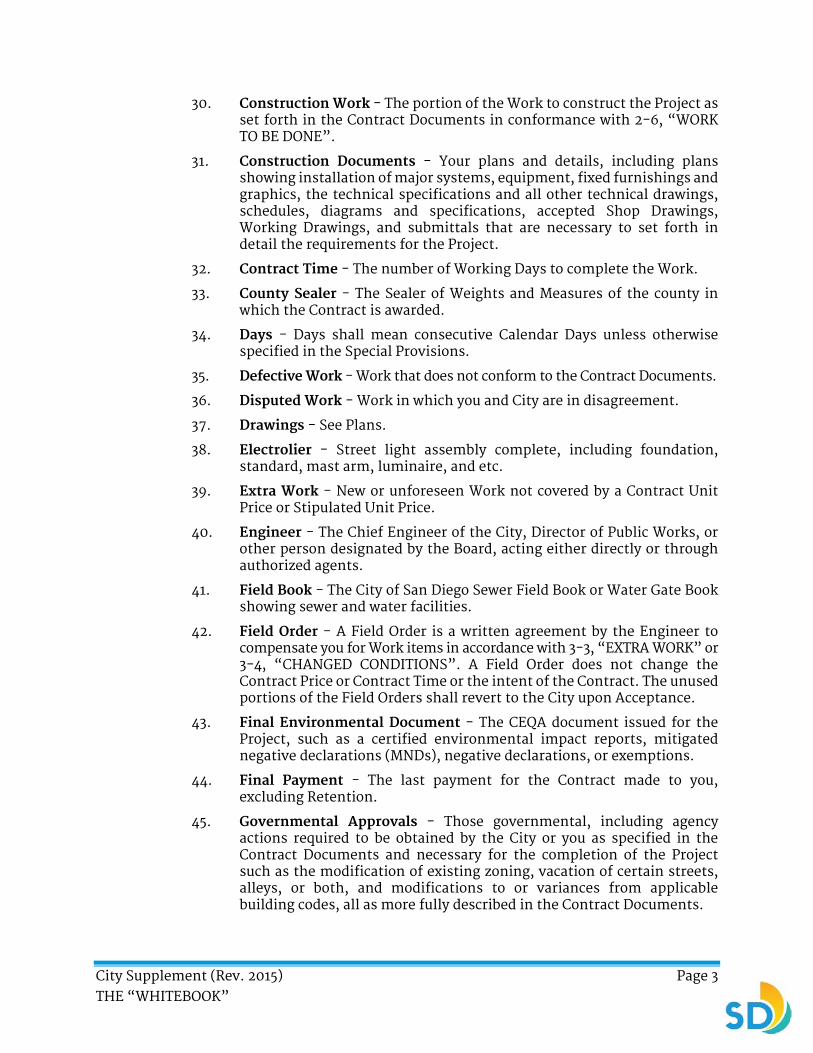
30. Construction Work - The portion of the Work to construct the Project as set forth in the Contract Documents in conformance with 2-6, “WORK TO BE DONE”.
31. Construction Documents - Your plans and details, including plans showing installation of major systems, equipment, fixed furnishings and graphics, the technical specifications and all other technical drawings, schedules, diagrams and specifications, accepted Shop Drawings, Working Drawings, and submittals that are necessary to set forth in detail the requirements for the Project.
32. Contract Time - The number of Working Days to complete the Work.
33. County Sealer - The Sealer of Weights and Measures of the county in which the Contract is awarded.
34. Days - Days shall mean consecutive Calendar Days unless otherwise specified in the Special Provisions.
35. Defective Work - Work that does not conform to the Contract Documents.
36. Disputed Work - Work in which you and City are in disagreement.
37. Drawings - See Plans.
38. Electrolier - Street light assembly complete, including foundation, standard, mast arm, luminaire, and etc.
39. Extra Work - New or unforeseen Work not covered by a Contract Unit Price or Stipulated Unit Price.
40. Engineer - The Chief Engineer of the City, Director of Public Works, or other person designated by the Board, acting either directly or through authorized agents.
41. Field Book - The City of San Diego Sewer Field Book or Water Gate Book showing sewer and water facilities.
42. Field Order - A Field Order is a written agreement by the Engineer to compensate you for Work items in accordance with 3-3, “EXTRA WORK” or 3-4, “CHANGED CONDITIONS”. A Field Order does not change the Contract Price or Contract Time or the intent of the Contract. The unused portions of the Field Orders shall revert to the City upon Acceptance.
43. Final Environmental Document - The CEQA document issued for the Project, such as a certified environmental impact reports, mitigated negative declarations (MNDs), negative declarations, or exemptions.
44. Final Payment - The last payment for the Contract made to you, excluding Retention.
45. Governmental Approvals - Those governmental, including agency actions required to be obtained by the City or you as specified in the Contract Documents and necessary for the completion of the Project such as the modification of existing zoning, vacation of certain streets, alleys, or both, and modifications to or variances from applicable building codes, all as more fully described in the Contract Documents.

City Supplement (Rev. 2015) Page 4 THE “WHITEBOOK”
46. Holiday - Holidays observed by the City are listed below:
Holiday Observed On
New Year’s Day January 1
Martin Luther King Day 3rd Monday in January
Presidents’ Day 3rd Monday in February
Caesar Chavez Day March 31
Memorial Day Last Monday in May
Independence Day July 4
Labor Day 1st Monday in September
Veteran’s Day November 11
Thanksgiving Day 4th Thursday in November
Christmas Day December 25
If any Holiday listed falls on a Saturday, the Saturday and the preceding Friday are both legal Holidays. If the Holiday falls on a Sunday, both Sunday and the following Monday shall be legal Holidays. Unless specified otherwise in the Contract Documents or authorized by the Engineer, do not work on Holidays.
47. House Connection Sewer - A sewer, within a public street or right-of-way, proposed to connect any parcel, lot, or part of a lot with a mainline sewer.
48. Limited Notice To Proceed (LNTP) - A written notice given from the City that authorizes you to start a limited amount of Work that, as described in the notice, is not Construction Work.
49. Luminaire - The lamp housing including the optical and socket assemblies (and ballast if so specified).
50. Mast Arm - The structural member, or bracket, which, when mounted on a Standard, supports the luminaire.
51. Mayor or designee - The City’s Mayor or a designated representative.
52. Modification - Includes Change Orders and Supplemental Agreements. A Modification may only be issued after the effective date of the Contract.
53. Night Work - See Working Night.
54. Normal Working Hours - Unless specified otherwise, Normal Working Hours shall be 7:00 AM to 5:00 PM, Monday through Friday, inclusive. Saturdays, Sundays, and City Holidays are excluded.

City Supplement (Rev. 2015) Page 5 THE “WHITEBOOK”
55. Notice of Award - The written notice by the City to the successful Bidder stating that, upon its compliance with the required conditions, the City shall execute the Contract.
56. Notice of Completion (NOC) - A document recorded with the County of San Diego to signify that the Work has been completed and accepted by the City.
57. Notice to Proceed (NTP) - A written notice given by the City to you fixing the date on which the Contract time shall start.
58. Operation, Maintenance, and Warranty Instructions - Documents published by manufactures of pre-manufactured products describing operation, maintenance, and any other action that shall be performed by the City as a condition for the manufacture to honor the specified warranty.
59. Owner - See City.
60. Party or Parties - The City, you, or both, their respective permitted successors or assigns, and any other future signatories to the Contract.
61. Person - Any individual, firm, association, partnership, corporation, trust, joint venture, or other legal entity.
62. Plans - The Drawings, profiles, cross sections, Standard Plans, Working Drawings, and Shop Drawings, or reproductions thereof, approved by the Engineer, which show the location, character, dimensions, or details of the Work.
63. Prime Contractor - See Contractor.
64. Private Contract - Work subject to City inspection, control, and approval, involving private funds, not administered by the City.
65. Private Development Projects - See Private Contract.
66. Project - The object of the Contract to be designed, constructed, or both by you as specified, described, and shown in the Contract Documents.
67. Project Site (Site) - Areas where the Work is performed pursuant to the Contract.
68. Proposal - See Bid.
69. Punchlist - A list of items of Work or corrections generated after a Walk-through that is conducted when you consider that the Work and Services are complete.
70. Quality Control Standards and Procedures - The standards and procedures that are stated in a written manual that can be furnished to the Engineer upon request. The standards and procedures are followed by the Supplier in the production of materials supplied to the Work site.
71. Red-lines - Plans with annotations of changes made during construction to reflect the actual product built during construction whether concealed or visible.

City Supplement (Rev. 2015) Page 6 THE “WHITEBOOK”
72. Reference Specifications - The latest edition, including amendments, in effect as of the date of advertisement of the Contract or issuing the permit, unless otherwise specified, of the following:
a) Bulletins
b) Standards
c) Rules
d) Methods of analysis or testing
e) Codes
f) Installation instructions
g) Specifications of other agencies, engineering societies, manufactures, or industrial associations referred to in the Contract Documents.
73. Retention - The amount withheld from the money due to you in accordance with 9-3.2, “Partial and Final Payment”.
74. Roadway - The portion of a street reserved for vehicular use.
75. Samples - Physical examples which illustrate materials, equipment, or workmanship and which establish standards that the Work shall be evaluated.
76. Schedule - A Critical Path Method (CPM) schedule prepared by you in accordance with 6-1, “Construction Schedule and Commencement of The Work” and accepted by the Engineer.
77. Scope of Work (SOW) - Labor, materials, equipment, facilities, and services required to be performed or provided by you to complete the entire Project or the various separately identifiable parts of the Project pursuant to the provisions of the Contract Documents.
78. Services - Professional services such as design, engineering, and construction management of the Project that are required in accordance with the Contract Documents. Services are included in the Work.
79. Service Connection - All or any portion of the conduit cable or duct, including meter, between a utility distribution line and an individual consumer.
80. Service Lateral Connection - The interface of the House Connection Sewer with the host pipe.
81. Separate Contractors - Those individuals or entities that have entered into arrangements with the City for the provision of labor, materials, or other services in connection with the Project who are not under contract with you.
82. Sewer - Any conduit intended for the reception and transfer of sewage and fluid industrial waste.
83. Shop Drawings - Drawings showing details of manufactured or assembled products proposed to be incorporated into the Work.
84. Signal Pre-Check - The procedure that the City uses to evaluate traffic signal systems prior to Signal Turn-On and generating a Punchlist.

City Supplement (Rev. 2015) Page 7 THE “WHITEBOOK”
85. Signal Turn-On - The day the City activates new traffic signals.
86. Special Provisions - Additions and revisions to the Standard Specifications setting forth conditions and requirements peculiar to the Work. Examples include the City’s EOCP Requirements, provisions for Design-Build and Job Order Contracting Contracts, funding agency provisions, technical specifications prepared in CSI format, City Supplement, and Supplementary Special Provisions (SSP).
87. Specifications - Standard Specifications, Reference Specifications, Special Provisions, and specifications in Change Orders or Supplemental Agreements between you and the City.
88. Standard - The shaft or pole used to support street lighting luminaires, traffic signal heads, mast arms, and etc.
89. Standard Plans - Details of standard structures, devices, or instructions referred to on the Plans or in the Specifications by title or number.
90. Standard Specifications - The Standard Specifications for Public Works Construction (SSPWC), the “GREENBOOK”.
91. State - State of California.
92. Stipulated Unit Price - Unit prices established by the City in the Contract Documents.
93. Storm Drain - Any conduit and appurtenances intended for the reception and transfer of storm water.
94. Street - Any road, highway, parkway, freeway, alley, walk, or way.
95. Subbase - A layer of specified material of planned thickness between the base and the subgrade.
96. Subcontractor - An individual, firm, or corporation having a direct contract with you or with any other Subcontractor for the performance of a part of the Work.
97. Subgrade - For roadways, that portion on which pavement, surfacing, base, subbase, or a layer of other material is placed. For structures, the soil prepared to support a structure.
98. Supervision - Supervision, where used to indicate supervision by the Engineer, shall mean the performance of obligations, and the exercise of rights, specifically imposed upon and granted to the City in becoming a party to the Contract. Except as specifically stated herein, supervision by the City shall not mean active and direct superintendence of details of the Work.
99. Supplemental Agreement - A written amendment of the Contract Documents signed by you and the City.
100. Surety - The company who issued the performance and payment bond.
101. Utility - Tracks, overhead or underground wires, pipelines, conduits, ducts, structures, sewers, or storm drains owned, operated, or maintained in or across a public right of way or private easement.

City Supplement (Rev. 2015) Page 8 THE “WHITEBOOK”
102. Walk-through - The procedure the City uses to evaluate the status of the Project and to generate a Punchlist prior to Acceptance.
103. Work - That which is proposed to be constructed or done under the Contract or permit, including the furnishing of all labor, materials, equipment, and services.
104. Working Day - Any day other than Holidays, Saturdays, and Sundays.
105. Working Night (Night Work) - Night Work is allowed only on Sunday through Thursday.
106. Working Drawings - Drawings showing details not shown on the Plans which are required to be designed by you.
107. Work Site - See Project Site (Site).
1-3.2 Common Usage. ADD the following:
1. AML ................. Approved Material List
2. CADD ............... Computer Aided Design and Drafting
3. CA MUTCD ........ California Manual on Uniform Traffic Control Devices
4. CCT .................. Correlated Color Temperature
5. CEQA ................ California Environmental Quality Act.
6. CFR .................. Code of Federal Regulations
7. CIPM ................ Cured-In-Place-Manhole
8. CMS ................. Content Management System Database
9. CNC ................. Computer Numerical Control
10. CRI ................... Color Rendering Index
11. CSA .................. Canadian Standards Association
12. DBE .................. Disadvantaged Business Enterprise
13. DCE .................. Data Computer Equipment
14. DG ................... Decomposed Granite
15. DVBE ................ Disabled Veteran Business Enterprise
16. DWT ................. Detectable Warning Tiles
17. EBE .................. Emerging Business Enterprise
18. ELBE ................ Emerging Local Business Enterprise
19. EOCP ................ Equal Opportunity Contracting Program
20. ESL .................. Environmentally Sensitive Lands
21. ESO .................. Electrical Service Orders
22. FRP .................. Fiberglass Reinforced Thermosetting Plastic
23. GFE .................. Good Faith Effort
24. GMT ................. Greenwich Mean Time
25. GPS .................. Global Positioning System
City Supplement (Rev. 2015) Page 9 THE “WHITEBOOK”
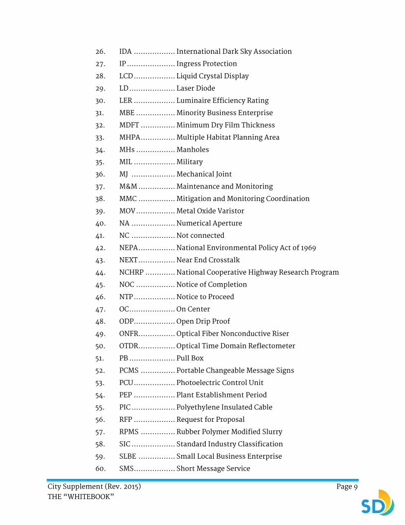
26. IDA .................. International Dark Sky Association
27. IP ..................... Ingress Protection
28. LCD .................. Liquid Crystal Display
29. LD .................... Laser Diode
30. LER .................. Luminaire Efficiency Rating
31. MBE ................. Minority Business Enterprise
32. MDFT ............... Minimum Dry Film Thickness
33. MHPA ............... Multiple Habitat Planning Area
34. MHs ................. Manholes
35. MIL .................. Military
36. MJ ................... Mechanical Joint
37. M&M ................ Maintenance and Monitoring
38. MMC ................ Mitigation and Monitoring Coordination
39. MOV ................. Metal Oxide Varistor
40. NA ................... Numerical Aperture
41. NC ................... Not connected
42. NEPA ................ National Environmental Policy Act of 1969
43. NEXT ................ Near End Crosstalk
44. NCHRP ............. National Cooperative Highway Research Program
45. NOC ................. Notice of Completion
46. NTP .................. Notice to Proceed
47. OC .................... On Center
48. ODP .................. Open Drip Proof
49. ONFR ................ Optical Fiber Nonconductive Riser
50. OTDR ................ Optical Time Domain Reflectometer
51. PB .................... Pull Box
52. PCMS ............... Portable Changeable Message Signs
53. PCU .................. Photoelectric Control Unit
54. PEP .................. Plant Establishment Period
55. PIC ................... Polyethylene Insulated Cable
56. RFP .................. Request for Proposal
57. RPMS ............... Rubber Polymer Modified Slurry
58. SIC ................... Standard Industry Classification
59. SLBE ................ Small Local Business Enterprise
60. SMS .................. Short Message Service

City Supplement (Rev. 2015) Page 10 THE “WHITEBOOK”
61. SMTP ................ Simple Mail Transfer Protocol
62. SOW ................. Statement of Work
63. SOV .................. Schedule of Values
64. SPDT ................ Single Pole Double Throw
65. SSD .................. Surge Suppression Devices
66. TDR .................. Time Domain Reflectometer
67. TEES ................. Transportation Electrical Equipment Specifications
68. TFFN ................ Thermoplastic Flexible Fixture Wire Nylon Jacketed
69. TIG ................... Tungsten Inert Gas
70. UF .................... Underground Feeder
71. UPRR ................ Union Pacific Rail Road Company
72. VAC .................. Volts AC
73. VPC .................. Vitrified Polymer Composite
74. WBE ................. Women Business Enterprise
1-3.3 Institutions. ADD the following:
1. AMTRACK ......... American Track National Railroad Passenger Corp.
2. BNSF ................ Burlington Northern Santa Fe Railway
3. DSD .................. Development Services Department
4. FHWA ............... Federal Highway Administration
5. IPCEA ............... Insulated Power Cable Engineers Association
6. IES ................... Illuminating Engineering Society (Photometric Data)
7. ISO ................... International Organization for Standardization
8. MTS.................. San Diego Metropolitan Transit System
9. NACE ................ National Association of Corrosion Engineers
10. NAFP ................ National Association of Pipe Fabricators
11. NCTD ............... North County Transit District
12. NFPA ................ National Fire Protection Association
13. PCI ................... Prestressed Concrete Institute
14. PUD .................. Public Utilities Department
15. SANDAG ........... San Diego Association of Governments
16. SD&AE .............. San Diego & Arizona Eastern Railroad
17. SDTI ................. San Diego Trolley, Inc.
18. SDUSD .............. San Diego Unified School District
19. UPRR ................ Union Pacific Rail Road Company
City Supplement (Rev. 2015) Page 11 THE “WHITEBOOK”
SECTION 2 - SCOPE AND CONTROL OF THE WORK
ADD:
2-1.1 Standard Contract Provisions.
2-1.1.1 Successor's Obligations.
1. All grants, covenants, provisions and claims, rights, powers, privileges and abilities contained in the Contract Documents shall be read and held as made by and with, and granted to and imposed upon, you, the City, and your and the City’s respective heirs, executors, administrators, successors, and assigns.
2-1.1.2 Waiver of Legal Rights.
1. The City’s failure to insist, in any one or more instances, upon the performance of any provision of the Contract, or to exercise any right therein, shall not be construed as a waiver or relinquishment of such provisions or rights.
2. Any waiver of any breach of the Contract shall not be held to be a waiver of any other or subsequent breach.
3. Any waiver the City issues to any provision of the Contract shall only be effective if it is agreed upon in writing by the City and if it is specific to the particular matter concerned.
2-1.1.3 Requests for Information (RFI).
1. Any questions related to how the Work is to be completed shall be submitted, in writing, to the City.
2-1.1.4 Headings.
1. Section headings are for convenience only and shall not affect the interpretation of the Contract.
2-1.1.5 Cumulative Remedies.
1. The duties and obligations imposed by the Contract and the rights and remedies available to the Parties, without limitation, of the warranties, guarantees, and obligations imposed upon you by the Contract and all of the rights and remedies available to the City are in addition to and are not to be construed in any way as a limitation of any rights and remedies imposed or available by Laws or Regulations, special warranties or guarantees, or by other provisions of the Contract Documents.
2-1.1.6 Assignment to Awarding Body.
1. In accordance with §7103.5(b) of the California Public Contract Code, you and your Subcontractors shall conform to the following requirements:
a) In entering into a public works contract or a Subcontract to supply goods, services, or materials pursuant to a public works contract, you or your Subcontractor offer and agree to assign to the awarding body all rights, title, and interest in and to all causes of action it may have under §4 of the Clayton Act (15 U.S.C. Sec. 15) or under the Cartwright Act (Chapter 2 (commencing with §16700) of Part 2 of

City Supplement (Rev. 2015) Page 12 THE “WHITEBOOK”
Division 7 of the Business and Professions Code) arising from purchases of goods, services, or materials pursuant to the public works contract or the Subcontract.
b) This assignment shall be made and become effective at the time the awarding body tenders to you, without further acknowledgment by the Parties.
2-3.1 General. ADD the following:
1. The use of Subcontractors in no way relieves you of any obligations or responsibilities under the Contract.
ADD:
2-3.1.2 Subcontractor List.
1. In compliance with the “Subletting and Subcontracting Fair Practices Act” (Public Contract Code §§4100-4114, inclusive), do not modify your listing of Subcontractors without the City’s written approval.
2. If at any time after Award of the Contract you identify a need for additional Subcontractor services, you shall immediately request in writing for the City’s consent. The request shall include a justification, a description of the Work, and an estimate of the costs for the services.
3. For Extra Work, you shall submit Form CC10, “CONTRACT CHANGE ORDER (CCO)” with each CCO proposal. Form CC10 is available for download from the City’s EOCP internet site: http://www.sandiego.gov/eoc/
2-3.3 Status of Subcontractors. ADD the following:
1. With every request for payment, submit to the Engineer a breakdown showing monthly and cumulative amounts of the Work performed under the Change Order by you and your Subcontractors. The reporting format shall be approved by the Engineer.
ADD:
2-3.4 Subcontract Requirements.
1. You shall incorporate the Specifications in the subcontracts to the extent of the Work to be performed by Subcontractor.
2. You shall obtain or require that each Subcontractor obtains insurance policies in accordance with 7-3, “INSURANCE” which shall be kept in full force and effect for the duration of the Contract and in any attached supplemental agreements.
3. In any dispute between you and your Subcontractors, the City shall not be made a party to any judicial or administrative proceeding to resolve the dispute.
4. You shall ensure that your Subcontractors are appropriately licensed for the duration of the Work that is performed under the subcontracts. In the event the Subcontractor is not properly licensed, you shall cease payment to the Subcontractor for all Work performed when the Subcontractor was not properly licensed. You shall return to the City any payment you made
City Supplement (Rev. 2015) Page 13 THE “WHITEBOOK”
to a Subcontractor for Work performed when the Subcontractor was not licensed.
5. Where the Contract Documents require that a particular product be installed or applied by an applicator approved by the manufacturer, ensure the Subcontractor or Supplier employed for such Work is approved by the manufacturer.
2-4 CONTRACT BONDS. DELETE in its entirety and SUBSTITUTE with the following:
1. Before execution of the Contract, file surety bonds with the City to be approved by the Board in the amounts and for the purposes noted. Bonds shall be executed by a responsible surety as follows:
a) If the Work is being funded with state or local money, consistent with California Code of Civil Procedure §995.670, the Surety shall be an “admitted surety” authorized by the State of California Department of Insurance to transact surety insurance in the State.
b) If the Work is being funded with federal money, the Surety shall be listed in the U.S. Treasury Department Circular 570 and shall be in conformance with the specified Underwriting Limitations.
2. Each bond shall incorporate, by reference, the Contract and shall be signed by both the Bidder and the Surety. The signature of the authorized agent of the Surety shall be notarized. You shall provide the following bonds:
a) For Contracts less than $10,000:
i. A “Payment Bond” (Materials and Labor Bond) is optional. If no bond is submitted, no payment shall be made until 35 Days after NOC has been recorded and any lien requirements have been fulfilled. If a bond is submitted, progress payments shall be made in accordance with these Specifications.
ii. A “Faithful Performance Bond” is not required.
b) For Contracts over $10,000 and less than $25,000:
i. A “Payment Bond” (Materials and Labor Bond) is optional. If no bond is submitted, progress payments may be made with a minimum of 20% retention. If a bond is submitted, progress payments shall be made in accordance with these Specifications.
ii. A “Faithful Performance Bond” is not required.
c) For Contracts over $25,000 and less than $100,000:
i. A “Payment Bond” (Materials and Labor Bond) for not less than 100% of the Contract Price to satisfy claims of material Suppliers and of mechanics and laborers employed on the Work. You shall maintain the bond in full force and effect until Acceptance and until all claims for materials and labor are paid and shall otherwise comply with the Government Code.
City Supplement (Rev. 2015) Page 14 THE “WHITEBOOK”
ii. A “Faithful Performance Bond” is not required.
d) For Contracts over $100,000 or where submitted on optional basis:
i. A “Payment Bond” (Materials and Labor Bond) for 100% of the Contract Price to satisfy claims of material Suppliers and of mechanics and laborers employed on the Work. You shall maintain the bond in full force and effect until Acceptance and until all claims for materials and labor are paid and shall otherwise comply with the Government Code.
ii. A “Faithful Performance Bond” for 100% of the Contract Price to guarantee faithful performance of Work, within the time prescribed and in a manner satisfactory to the City, that materials and workmanship shall be free from original or developed defects.
e) For Contracts over $100,000 which include Community Development Block Grant (CDBG) - HUD Program Funds:
i. A “Payment Bond” (Material and Labor Bond) for 100% of the Contract Price to satisfy claims of material Suppliers and of mechanics and laborers employed on the Work. You shall maintain the bond in full force and effect until the Acceptance and until all claims for materials and labor are paid and shall otherwise comply with the Government Code.
ii. A “Faithful Performance Bond” for 100% of the Contract Price to guarantee faithful performance of Work, within the time prescribed and in a manner satisfactory to the City, that materials and workmanship shall be free from original or developed defects.
3. Should any bond become insufficient, renew the bond within 10 Days after receiving notice from the City. Should any surety at any time be unsatisfactory to the Board, notice to that effect shall be given. No further payments shall be deemed due or shall be made under the Contract until a new surety qualifies and is accepted.
4. Changes in the Work or extensions of time, made pursuant to the Contract, shall in no way release you or the Surety from its obligations. Notice of such changes or extensions shall be waived by the Surety.
5. The bond shall remain in effect until the end of warranty period set forth in the Contract Documents.
6. If the Surety on any bond furnished by you is declared bankrupt, becomes insolvent, or its right to do business is terminated in any state where any part of the Project is located, immediately notify the Engineer and immediately substitute another bond and surety acceptable to the City.

City Supplement (Rev. 2015) Page 15 THE “WHITEBOOK”
7. You shall require the Surety to mail its standard “Bond Status” form to the Engineer at the following address:
Deputy Director
Construction Management and Field Services Division
9485 Aero Drive
San Diego, CA 92123
ADD:
2-4.1 Bond Payments.
1. The Bid item for “Bonds (Payment and Performance)” includes full compensation for actual costs of payment and performance bonds. You may submit a request for payment of actual invoiced costs up to the bid amount, but not to exceed 2.5% of the Contract Price, no less than 10 Working Days after the award of the Contract.
2. If the Bid item for “Bonds (Payment and Performance)” exceeds actual invoiced costs, any such differential amount up to the bid amount shall be paid as a part of the Final Payment.
2-5.1 General. ADD the following:
1. Specifications and Plans are divided into groups by engineering discipline for the City’s convenience. These divisions are not for the purpose of apportioning the Work or responsibility for the Work among Subcontractors and Suppliers.
2. You shall supply any Work that may reasonably be inferred from the Specifications or Plans as being required to produce the intended result whether or not it is specifically called for, at no additional cost to the City.
3. References to specified software, guides, standard specifications, manuals or codes of any technical society, organizations or associations, or to the codes of any governmental authority, whether such reference is specific or is implied, mean the latest edition or version in effect when the Contract is advertised (or on the effective date of the Contract if there were no Bids), unless specified otherwise.
4. If referenced documents have been discontinued by the issuing organization, references to those documents means the replacement documents issued or otherwise identified by that organization or, if there are no replacement documents, the last version of the document before it was discontinued.
2-5.2 Precedence of Contract Documents. DELETE in its entirety and SUBSTITUTE with the following:
1. If there is a conflict between any of the Contract Documents, the document highest in the order of precedence shall control. The order of precedence, from highest to lowest, shall be as follows:
a) Permits (issued by jurisdictional regulatory agencies including environmental documents).

City Supplement (Rev. 2015) Page 16 THE “WHITEBOOK”
b) Change Orders and Supplemental Agreements; whichever occurs last.
c) The signed written Agreement.
d) Addenda.
e) Bid / Proposal.
f) Supplemental Special Provisions.
g) Project Plans.
h) Standard Drawings.
i) “WHITEBOOK” (City Supplement).
j) “GREENBOOK” (Standard Specifications for Public Works Construction).
k) Reference Specifications.
2. When additional EOCP requirements by the funding sources are included or incorporated by reference in the Contract Documents, the funding source’s requirements shall govern unless specified otherwise in the SSP.
3. With reference to the Drawings, the order of precedence shall be as follows:
a) Figures govern over scaled dimensions.
b) Detail Drawings govern over general Drawings.
c) Addenda and Change Order Drawings govern over Plans.
d) Plans govern over Standard Drawings.
4. When a conflict exists between the ADA, Title 24, and the City Supplement, the most restrictive requirement shall be followed.
5. When there is a conflict between subsection 700-3.3, “Standards”, Section 86 of the May, 2015 Standard Specifications and the May, 2015 Standard Plans of Caltrans, the Caltrans standards shall control.
2-5.3.1 General. ADD the following:
1. For products for which a City Approved Materials List (AML) is available, products listed in the AML shall be used. For more information, visit the City’s website at:
http://www.sandiego.gov/publicworks/edocref/index.shtml
2. A submittal review shall be conducted for products not identified on an AML on a case-by-case basis when:
a) The product type or category is not in the AML.
b) The AML does not list at least two available manufacturers of the product.
c) The material or manufacturer listed in the AML is no longer available. Documentation to substantiate the product is no longer available or in production is required as part of the submittal.
i. In the case of conducting a submittal review when required by the Plans or Special Provisions or when requested by the

City Supplement (Rev. 2015) Page 17 THE “WHITEBOOK”
Engineer, all submittals shall be accompanied by the City’s submittal form. The Product Submittal Form is available for download at:
http://www.sandiego.gov/publicworks/edocref/index.shtml
2-5.3.2 Working Drawings. DELETE in its entirety and SUBSTITUTE with the following:
1. Working Drawings shall be of a size and scale to clearly show all necessary details.
2. Six (6) copies and 1 reproducible shall be submitted. If no revisions are required, 3 of the copies shall be returned. If revisions are required, the Engineer shall return 1 copy along with the reproducible for resubmission. Upon acceptance, the Engineer shall return 2 of the copies and retain the remaining copies and the reproducible.
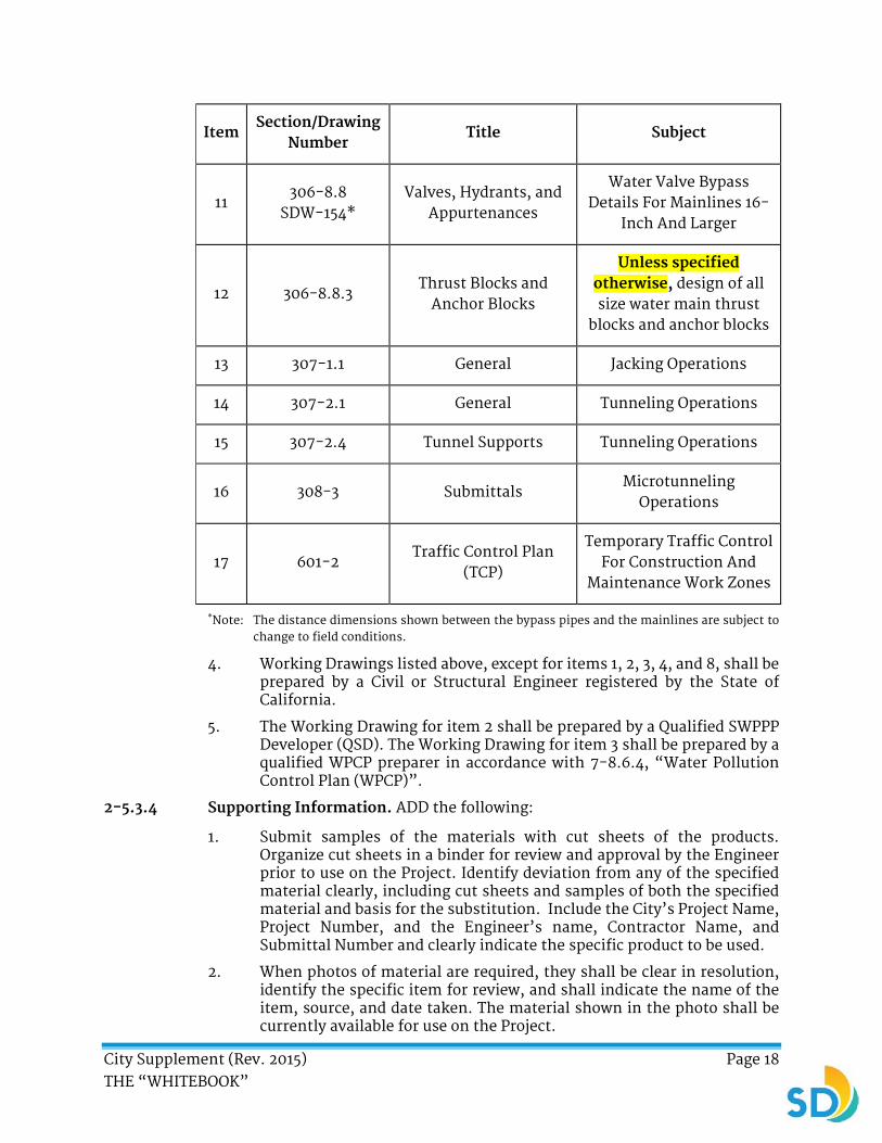
3. Working Drawings are required in the subsections shown in Table 2-5.3.2.
TABLE 2-5.3.2
Item Section/Drawing
Number Title Subject
1 7-8.5.2 Sewage Bypass and
Pumping Sanitary Sewers
2 7-8.6.3 Storm Water Pollution
Prevention Plan (SWPPP)
Water Pollution Control
3 7-8.6.4 Water Pollution Control
Plan (WPCP) Water Pollution Control
4 7-8.6.6.2 Dewatering Plan Water Pollution Control
5 7-10.4.2.2 Shoring Plan Safety
6 300-3.2 Cofferdams Structure Excavation &
Backfill
7 303-1.6.1 General Falsework
8 303-1.7.1 General Placing Reinforcement
9 303-3.1 General Prestressed Concrete
Construction
10 304-1.1.2 Falsework Plans Structural Steel
City Supplement (Rev. 2015) Page 18 THE “WHITEBOOK”
Item Section/Drawing
Number Title Subject
11 306-8.8
SDW-154* Valves, Hydrants, and
Appurtenances
Water Valve Bypass Details For Mainlines 16-
Inch And Larger
12 306-8.8.3 Thrust Blocks and
Anchor Blocks
Unless specified otherwise, design of all size water main thrust
blocks and anchor blocks
13 307-1.1 General Jacking Operations
14 307-2.1 General Tunneling Operations
15 307-2.4 Tunnel Supports Tunneling Operations
16 308-3 Submittals Microtunneling
Operations
17 601-2 Traffic Control Plan
(TCP)
Temporary Traffic Control For Construction And
Maintenance Work Zones
*Note: The distance dimensions shown between the bypass pipes and the mainlines are subject to change to field conditions.
4. Working Drawings listed above, except for items 1, 2, 3, 4, and 8, shall be prepared by a Civil or Structural Engineer registered by the State of California.
5. The Working Drawing for item 2 shall be prepared by a Qualified SWPPP Developer (QSD). The Working Drawing for item 3 shall be prepared by a qualified WPCP preparer in accordance with 7-8.6.4, “Water Pollution Control Plan (WPCP)”.
2-5.3.4 Supporting Information. ADD the following:
1. Submit samples of the materials with cut sheets of the products. Organize cut sheets in a binder for review and approval by the Engineer prior to use on the Project. Identify deviation from any of the specified material clearly, including cut sheets and samples of both the specified material and basis for the substitution. Include the City’s Project Name, Project Number, and the Engineer’s name, Contractor Name, and Submittal Number and clearly indicate the specific product to be used.
2. When photos of material are required, they shall be clear in resolution, identify the specific item for review, and shall indicate the name of the item, source, and date taken. The material shown in the photo shall be currently available for use on the Project.

City Supplement (Rev. 2015) Page 19 THE “WHITEBOOK”
2-5.3.6 Manufacturer's Operation, Maintenance, and Warranty Instructions. To Sentence (1), DELETE in its entirety and SUBSTITUTE with the following:
For each pre-manufactured product covered by a manufacturer's warranty, you shall submit 1 electronic copy and 3 bound original or legal copies prior to acceptance of the Contract.
ADD:
2-5.4 Red-lines and Record Documents.
2-5.4.1 General.
1. Keep to the satisfaction of the Engineer accurate, legible, and current records on a set of full size Plans of additions and deletions to the Work and of changes in location, elevation, and character of the Work not otherwise shown or noted in the Contract Documents.
2. Coordinate Red-lines drawings with field measurements, approved Shop Drawings, Working Drawings, samples, product data, and available records. You shall immediately give written notice of any conflicts between these documents to the Engineer.
3. Keep the Red-lines current with entries checked by the Engineer before the Work is buried or covered. Your failure to update and deliver Red-lines information monthly to the Engineer for review and approval may result in the withholding of monthly progress payments.
4. Note the source identification, such as RFI numbers and Change Order numbers, as required identifying the source of the change to the Contract Documents.
5. Deliver the Red-lines to the Engineer upon completion of the construction Work.
2-5.4.2 Asset Specific Red-lines.
1. Irrigation System Red-lines: Red-lines shall clearly record by dimension from 2 known fixed points and by depth of underground facilities all deviations, modifications, and changes in the Work. Records, deviations, modifications, and changes on the day the Work is performed shall reflect the actual Work location and shall be marked in red at the scale of the Plan sheet on which they are recorded. Red-lines shall show the equipment locations and associated information for the following:
a) Water Meter - Size, type of water (potable or reclaimed), and water meter address.
b) Electrical Meter, including meter address.
c) Backflow Device - Size, available static pressure in psi, the psi and flow in gallons per minutes for which the irrigation system is designed, and device serial number.
d) Irrigation Controller - Location, number of stations, identifying call-out.
e) Master Control Valve.

City Supplement (Rev. 2015) Page 20 THE “WHITEBOOK”
f) Flow Sensor.
g) Pressure Regulator Valve.
h) Isolation Valves.
i) Remote Control Valves - Size, irrigation controller, valve station number, and flow demand in gallons per minute.
j) Quick Cou4pling Valves and Size.
k) Irrigation Mainline and Size.
l) Potable Water Mainline and Size.
m) Irrigation Lateral Line and Size.
n) Irrigation Sleeves and Size.
o) Remote Control Valve Wiring.
p) Communication Cables.
q) Pull Boxes.
r) Rain Shut Off Switch.
s) Electrical lines from electrical meter to irrigation controller, including the power disconnect switch.
t) Irrigation sprinkler heads which have been added or deleted from the approved plans. Changes in manufacturer nozzle size shall be noted on the red-lined drawings including operating pressure, gallons per minute, and radius of throw.
2. Re-vegetation Red-lines:
a) Within 4 weeks of the end of the Plant Establishment Period, as determined and accepted by the Project Biologist, furnish and submit to the Engineer 1 full scale Red-lines set showing field changes to grade, erosion control, and seeding for the revegetated areas.
3. Utility Red-lines: Utility Red-lines shall show the location of the following:
a) Blow off valves by stationing and offsets.
b) Air vacuum valves by stationing and offsets.
c) Water meter boxes replaced.
d) Locations of all sewer laterals and cleanouts.
e) Items abandoned in place following dewatering operation.
4. Building Red-lines: Building Red-lines shall show the following:
a) Location by dimension and the depth by elevation of underground lines, valves, plugged tees, and capped ends.
b) By dimension or scale plans, wiring, conduits, and pull boxes as installed.

City Supplement (Rev. 2015) Page 21 THE “WHITEBOOK”
c) Information necessary to maintain and service concealed items of Work.
d) Dimensional changes to the drawings.
e) Revisions to details shown on the drawings.
f) Depths of foundations below the first floor.
g) Locations and depths of underground utilities.
h) Revisions to the routing of piping and conduits.
i) Revisions to electrical circuitry.
j) Actual equipment locations.
k) Duct size and routing.
l) Locations of concealed internal utilities.
m) Changes made by Change Orders.
n) Details not shown on original Plans.
5. Traffic Signals and Street Lighting:
a) Provide the Engineer with a cable route diagram indicating the actual cable route and meter marks for all intersections, directional change points in the cable routing, and all termination points. Record these points during cable installation. Provide cable system Red-lines showing the accurate cable route to the Engineer. Record information such as the location of slack cable and its quantity in the cable route diagram.
b) Provide 3 copies of D-Sheet sized Red-lines.
6. SWPPP:
a) Upon completion of construction, submit the SWPPP and all of its appendices, records, reports, and maps to the Engineer with the Red-lines.
7. Slurry Seal and Asphalt Concrete Overlay:
a) Clearly record on the forms the City provides in MS Excel format the actual dates and quantity of each Bid item applied to each street segment and comments regarding each segment. Record reasons if no Work is performed.
2-5.4.3 Payment.
1. The payment for Red-lines Drawings shall be included in the Contract Price.
ADD:
2-5.5 Measurements and Dimensions.
1. Scaled dimensions are approximate. Before ordering materials or commencing the Work, measure the Site for proper size and fit. Verify dimensions and quantities by taking measurements in the field. You shall be responsible for their accuracy.

City Supplement (Rev. 2015) Page 22 THE “WHITEBOOK”
2-6 WORK TO BE DONE. ADD the following:
1. Where approval or acceptance by the City is required, you shall understand it to be a general approval only and that it does not relieve you from your responsibility for complying with all applicable laws, codes, and best industry practices.
2. In accordance with the provisions of California Law, you shall possess or require the Subcontractor(s) to possess valid appropriate license(s) for the Work being performed.
2-7 SUBSURFACE DATA. DELETE in its entirety and SUBSTITUTE with the following:
1. All soil and test hole data, groundwater elevations, and soil analyses shown on the Plans or included in the Special Provisions apply only at the location of the test holes and to the depths indicated. Additional subsurface exploration may be performed at your own expense.
2. The indicated groundwater elevation is that which existed on the date specified in the data. It shall be your responsibility to determine and allow for the groundwater elevation on the date the Work is performed. A difference in groundwater elevation between what is shown in soil boring logs and what is actually encountered during construction shall not be considered as a basis for Extra Work in accordance with 3-3, “Extra Work”.
3. If reports of explorations and tests of Site conditions are referenced in the Contract Documents, you are encouraged to inspect the Site, acquire and review these reports, and take other necessary steps to thoroughly familiarize yourself with the Site conditions. If a review of the documents and Site inspection indicate an obstruction or utility conflict with the proposed Work, immediately notify the Engineer.
2-8 RIGHT-OF-WAY. ADD the following:
1. You shall be responsible for coordinating with property owners with timing and when access is provided through rights of entry and shall protect private improvements.
2-9.1 Permanent Survey Markers. DELETE in its entirety and SUBSTITUTE with the following:
1. Pursuant to Division 3, Chapter 15 of the Business and Professions Code, you shall not disturb survey monuments that “control the location of subdivisions, tracts, boundaries, roads, streets, or highways, or provide horizontal or vertical survey control” until they have been tied out by a Registered Land Surveyor or Registered Civil Engineer authorized to practice land surveying within the State of California.
2. Monument Preservation shall be performed by the City’s Construction Management and Field Services (CMFS) Division on all Projects, unless permission is obtained for these services in writing by CMFS.
3. You shall submit to the Engineer a minimum of 7 Days prior to the start of the Work a list of controlling survey monuments which may be disturbed. CMFS shall do the following:

City Supplement (Rev. 2015) Page 23 THE “WHITEBOOK”
a) Set survey points outside the affected Work area that reference and locate each controlling survey monument that may be disturbed.
b) File a Corner Record or Record of Survey with the County Surveyor after setting the survey points to be used for re-establishment of the disturbed controlling survey monuments.
c) File a Corner Record of Record of Survey with the County Surveyor after re-establishment of the disturbed controlling survey monuments.
2-9.2 Survey Service. ADD the following:
1. For Private Contracts, the engineer or surveyor shall request a right of entry to perform survey services on sewer mains and manholes from Wastewater Collection Division, Station 38 at 619-527-7500, 7 Days prior to the start of survey services.
2-9.3 Private Engineers. DELETE in its entirety.
2-11 INSPECTION. ADD the following:
1. The City may utilize consultants to assist the Engineer during construction in observing your performance. The consultant is for the purpose of assisting the Engineer and shall not be confused with a building inspector with the City or with a Special Inspector.
2. Code compliance testing (including Special inspection and all Geotechnical requirements) and inspections required by codes or ordinances is your responsibility, unless otherwise specified in the Contract Documents.
3. Your quality control testing and inspections is your responsibility. Coordinate and schedule all inspections and tests. Give the Engineer notice of when and where tests and inspections are to be made by others. Give at least 5 Working Days of notice for offsite inspection. Notices are not deemed effective until the Engineer has responded and agreed to your schedule.
4. The City shall make any inspections and tests as the City deems necessary to ensure the Work is accomplished in accordance with the requirements of the Contract Documents (other than inspections for Work performed in accordance with a permit). You are responsible for the inspection of all Work performed in accordance with a permit.
5. Provide access in accordance with Cal-OSHA Standards where necessary.
6. Remove and replace any items of Work performed without the required permit. For required subsequent inspection, remove and replace Work at the discretion of Engineer at no additional cost to the City. Inspection of the Work does not relieve you of full compliance with the Contract Documents.
7. Do not cover the Work prior to inspection, testing, or approval required by the Contract Documents, the Engineer’s prior written request, or by other agencies. If any item of Work is covered prior to obtaining the required approvals, when requested by the Engineer, uncover the Work

City Supplement (Rev. 2015) Page 24 THE “WHITEBOOK”
for inspection, testing, and/or approval. Upon successful completion of the inspection, testing, or approval, cover the Work afterwards again where required. You bear all direct and indirect costs and damages of such uncovering and re-covering and are not entitled to an increase in the Contract Price or the Contract Time, unless you have given the Engineer and any other affected agencies written notice of your intention to cover the Work and the Engineer has not acted in response to such notice.
8. When specified, make arrangements for tests, inspections, and approvals with an independent testing laboratory or entity acceptable to the Engineer, or with the appropriate public authority. The payment for such tests, inspections, and approvals are included in the Contract Price.
9. Unless specified otherwise, you shall pay the cost of inspections and tests. In the event that inspections or tests reveal non-compliance with the requirements of the Contract Documents, you shall bear the cost of corrective measures deemed necessary by the Engineer and the cost of the City’s subsequent re-inspection and re-testing.
ADD:
2-11.1 Remote Control Camera Inspection.
2-11.1.1 General.
1. A time lapse video robotic camera shall be installed on all stationary project sites and Group Jobs where open trench pipe installation is to take place. A camera is not required for Operations and Maintenance type projects such as slurry, overlay, and sidewalk panel replacement. The camera shall be installed at a location where most construction activity shall be captured and remain operational throughout the project. The selected location shall be approved by the Engineer prior to installation.
a) The camera(s) shall be operational during all hours and days when excavation, pipe installation, and backfill is taking place. Time lapse video robotic cameras shall provide a clear view of backfill and compaction operations. For Group Jobs or other linear projects, the camera shall be mounted on a portable tower or similar device and repositioned as Work progresses.
b) The camera shall be Heavy Duty Outdoor Vehicle Mounted RobotCam System manufactured by EarthCam, Inc. or approved equal.
c) The camera shall be removed when installed on permanent project locations or fixtures. Electrical services shall be deactivated and properly concealed and mounting hardware shall be removed to the satisfaction of the Engineer.
2-11.1.2 System Requirements.
1. The camera system shall feature:
a) An outdoor robotic infrared camera system.

City Supplement (Rev. 2015) Page 25 THE “WHITEBOOK”
b) A compact and rugged PTZ camera designed to endure the harsh elements from extreme temperatures and caustic environments such as salt air.
2. The system shall include:
a) A vibration isolation feature, providing jitter-free video for applications that call for mobility.
b) A heavy-duty camera, video web caster, and matched cellular modem in a rugged all weather enclosure with 12 VDC Power cord with lugs for vehicle battery power connection with Fuse/Diode-protected power cord.
3. The indoor and outdoor robotic camera system shall consist of nitrogen charged powder coated aluminum housing with an impact resistant viewing window and fiberglass equipment enclosure.
4. The camera shall have the ability to take still images every 5 minutes and shall have the ability to provide live video at 1 frame per second (FPS).
5. The camera shall upload the still images over a wireless cellular modem or hardwire connection to a DSL or cable modem.
6. The content shall be sent to a secure and password protected website with interface and online software features provided by the vendors as a managed service.
7. The system shall operate on 12 VDC and shall have a maximum power consumption of 30 W.
8. The system shall be available with an optional wiper and sun shield.
2-11.1.3 Equipment.
1. The robotic camera shall be a pressurized marine grade robotic outdoor infrared camera with a remotely controlled focal lens with the following features:
a) Pan angle range 440
b) Tilt angle range 240
c) Max pan speed 135/s
d) Max tilt speed 50/s
e) Pan/tilt encoder resolution 0.5
f) Housing material cast aluminum
g) Vibration 3 grms 3 axis, random, 5 to 1000 Hz
h) Temperature -4 F to 158 F (-20 C to 70 C)
i) Mounting quick connect
j) Zoom 26x optical, 12x digital
k) Imaging code color/near infrared
l) Resolution 470NTSC, 460PAL TV Lines
m) Pixel count 680,000 NTSC / 800,000 PAL

City Supplement (Rev. 2015) Page 26 THE “WHITEBOOK”
n) Dynamic range 50 dB
o) Light sensitivity 0.05 Lux NIR mode
p) Auto features Focus, ISO, iris, shutter, and white balance
q) Optional Infrared camera core 320 x 240
r) Heater built in thermostatically controlled
s) Window impact resistant viewing window
t) Window wiper remotely controlled
u) Sun shield optional
v) Dimensions 6.73 inch (171 mm) W x 7.8 inch (198 mm) H, and 7 inch (180 mm) in diameter.
w) Power 12 VDC, 2A peak
x) Weight of 9.04 lbs (4.1kg)
2-11.1.4 Electronics Enclosure.
1. The electronic enclosure shall conform to the following:
a) IP66 fiberglass enclosure.
b) EVDO-RevA cellular modem built in.
c) EarthCam video webcaster built-in.
d) Dimensions: 14.55 inch H x 12.55 inch W x 8.31 inch D (37 cm H x 31.9 cm W x 21.1 cm D).
e) Operational Voltage: 12 VDC.
2-11.1.5 Interface and Online Software.
1. Online interface shall feature the following:
a) Software delivered by vendor as a managed service.
b) Displays agency logo and project name.
c) Capable of viewing live video.
d) Robotic pan, tilt, zoom control of camera system.
e) Calendar based navigation system for selecting specific images.
f) Multifunction images browsing.
g) Record up to 120 hours of video.
h) Share image snapshots, video clips, and entire events seamlessly.
i) A multi-view screen to view all cameras for the Project at the same time.
j) Graphical mark-up tools for detailing and creating overlays on images.
k) Graphical weather applet displaying 10 points of location weather data.
City Supplement (Rev. 2015) Page 27 THE “WHITEBOOK”
l) Share image tools allowing for saving, printing, emailing, and posting to message boards or mobile devices.
m) Aerial and satellite photography library.
n) Time lapse features that include instant time lapse play back by day, week, month, or year.
o) Machine to machine self-healing technology automating maintenance of camera up to 288 times daily.
p) Account security features that include 4 levels of password protection, IP address blocking/permission, and SSL protection of User Login Password.
2-11.1.6 Payment.
1. The payment for the remote control camera inspection shall be included in the Contract Price unless a Bid item for “Remote Control Camera Inspection” has been provided.
ADD:
2-13 FORMAL PARTNERING.
1. You may request the formation of a formal partnering relationship (Partnering) by submitting a request in writing to the Engineer after approval of the Contract. If your request for Partnering is approved by the Engineer, scheduling of a Partnering workshop, selecting the Partnering facilitator and workshop, selecting the Partnering facilitator and workshop site, and other administrative details shall be as agreed to by both Parties.
2. The establishment of a Partnering shall not change or modify the terms and conditions of the Contract and shall not relieve either party of the legal requirements of the contract.
3. The goals of partnering include the following:
a) The Engineer and your representatives, including your Subcontractors, actively working together as partners.
b) Avoidance of destructive confrontation and litigation among the parties.
c) Mutual understanding on how the Work is to be conducted.
d) Establishment of mutual key results to facilitate Project success.
e) Establishment of an atmosphere of team work, trust, and open communication.
2-13.1 Payment.
1. The payments for providing a facilitator and a workshop site shall be borne equally by the City and you. You shall pay in advance all compensation for the costs of the facilitator and for the costs of obtaining the workshop site.
2. Unless a Bid item has been provided for “Partnering”, the City’s share of such costs shall be reimbursed to you as Extra Work. Markups shall not

City Supplement (Rev. 2015) Page 28 THE “WHITEBOOK”
be added. Other costs associated with the Partnering relationship shall be borne separately by the party incurring the costs.
ADD:
2-14 SITE ACTIVITIES BY THE CITY OR SEPARATE CONTRACTORS.
2-14.1 The City’s Right to Award Separate Contracts.
1. The City reserves the right to perform work or operations outside the Scope of Work of the Contract related to the Project with City Forces, Separate Contractors, or both. If work to be performed by another party was not noted in the Contract, the City shall give written notice to you 10 Working Days prior to the start of any work. If you determine that the work being performed by the City or others may interfere with or cause damage to Work being performed by you, notify the Engineer in writing within 3 Working Days of the Engineer’s notice.
2-14.2 Integration of the Work with Separate Contractors.
1. When specified in the Contract Documents, prepare a plan in order to integrate the work performed by Separate Contractors, City Forces, or both with the performance of the Work and submit the plan to the Engineer for approval. The plan shall be fair and reasonable for you and the Separate Contractors. Work with Separate Contractors to reach an agreement for the prepared plan. Arrange the performance of the Work so that the Work and the work of the Separate Contractors are, to the extent applicable, properly integrated and jointed in a manner that avoids any damage to the Work or to the work of the Separate Contractors.
2-14.3 Coordination.
1. Coordinate your activities and the Schedule with the activities and schedules of the Separate Contractors and make any revisions to the Schedule deemed necessary to avoid any disruption to the Work or to the work of the Separate Contractors.
2-14.4 Use of Site.
1. Provide the City and the Separate Contractors reasonable opportunities for the storage of materials and equipment and performance of their work. Connect and coordinate Work and operations with the work and operations of the City and the Separate Contractors as required by the Contract Documents.
2. Coordinate traffic control with the Separate Contractors for other projects and minimize the impact to the community. Prior to the start of construction, submit your plan for coordination.
2-14.5 Deficiency in Work of Separate Contractors.
1. If part of your Work depends on proper execution or results upon construction or operations by the City or a Separate Contractor, prior to proceeding with that portion of the Work, promptly report to the Separate Contractor and the Engineer any apparent discrepancies or defects in construction that would render it unsuitable for proper

City Supplement (Rev. 2015) Page 29 THE “WHITEBOOK”
execution and results. Use good faith efforts to resolve any such discrepancies or defects or any related disagreements. Your failure to report constitutes your acceptance of the Work of Separate Contractors as fit, proper, and coordinated with the Work.
2-14.6 Payment.
1. Payment for reporting deficiencies, coordinating, and resolving discrepancies shall be included in the Contract Price.
ADD:
2-15 TECHNICAL STUDIES AND DATA.
1. You are encouraged to inspect the Site, acquire and review this information, and to take other necessary steps to thoroughly familiarize yourself with the Site conditions. If a review of the documents and Site inspection indicate a conflict, immediately notify the Engineer.
2. Additional exploration may be performed by you at your own expense.
ADD:
2-16 CONTRACTOR REGISTRATION AND ELECTRONIC REPORTING SYSTEM.
1. Prior to the Award of the Contract, you, your Subcontractors, and your Suppliers shall register with the City’s web-based contract compliance at Prism® portal at the following:
https://pro.prismcompliance.com/default.aspx
2. Following NTP, you shall use Prism® for EOCP reporting purposes. This includes Weekly Certified Payroll, Monthly Employment Utilization, and Monthly Payments. Online tutorials are available at:
http://stage.prismcompliance.com/etc/vendortutorials.htm
ADD:
2-17 INFORMATION SECURITY POLICY (ISP).
1. The Contract is subject to the City’s Information Security Policy as defined in the City’s Administrative Regulation 90.63. By submitting a Bid, you agree to fully comply with the ISP. Full text of the ISP and the Administrative Regulation 90.63 can be requested from the Contract Specialist.
2. Your failure to abide by the City’s Administrative Regulation 90.63 shall be a breach of the Contract. You shall notify employees of their ISP responsibilities and shall post a copy of the following statement in an area frequented by employees who access the City’s computer systems:
a) Uses of City computer equipment, network services, electronic systems, and electronic data, including Email and Internet services, are for City business or Work-related purposes. The use of City computer equipment or information technology services for personal use shall be prohibited.
b) Computer files developed, created, or enhanced within the scope and course of City contract employment, or a City third-party

City Supplement (Rev. 2015) Page 30 THE “WHITEBOOK”
contractual relationship, are the property of the City of San Diego regardless of their physical location or the form in which they are maintained.
c) The City reserves the right to access and disclose all messages and other electronic data sent over its Email systems or stored in computer files on City Computer Equipment. The City-related computer files created, developed, or enhanced on remote access personal computers shall be provided upon the City’s request in City standard formats.
d) Users shall be responsible in their use of City computer equipment and network services. Any action that may cause interference with City computer systems, exposes the City’s computer systems to risk, or adversely impacts the work of others in using these computer systems is prohibited.
e) Every end user shall have a single unique user ID and a personal password which shall be kept confidential. This user ID and password shall be required for access to all multi-user computer equipment and network services. User passwords shall comply with the Information Security Guidelines and Standards.
f) Users accessing City computer systems are prohibited from gaining unauthorized access to any other computer systems or in any way damaging, altering, or disrupting the operations of these systems. Users are prohibited from capturing or otherwise obtaining passwords, encryption keys, or any other access control mechanism which could permit unauthorized access.
g) You shall give the Engineer access to documents and records sufficient for the Engineer to verify that you are complying with ISP requirements.
City Supplement (Rev. 2015) Page 31 THE “WHITEBOOK”
SECTION 3 - CHANGES IN WORK
3-1.1 General. ADD the following:
1. Any plan or method of Work suggested to you by the City, but not specified or required by the Contract or Change Order, which is adopted or followed by you in whole or in part shall be done at your sole risk and responsibility.
2. The Contract Price is not subject to adjustment due to sales tax increases after the Award.
ADD:
3-1.3 Cost Reduction Proposal.
1. You may submit to the Engineer in writing, proposals for modifying the Plans, Specifications, or other requirements of the Contract for the sole purpose of reducing the total cost of construction.
2. The cost reduction proposal shall not impair, in any manner, the essential functions or characteristics of the Project such as service life, economy of operation, ease of maintenance, desired appearance, or design and safety standards.
3. Include the following information in the cost reduction proposal:
a) A description of both the existing Contract requirements for performing the Work and the proposed changes.
b) An itemization of the Contract requirements that shall be changed if the proposal is adopted.
c) A detailed estimate of the cost of performing the Work under the existing Contract and under the proposed change.
d) A statement of the time within which the Engineer shall make a decision.
e) The Contract items of Work affected by the proposed changes, including any quantity variation attributable thereto.
4. These provisions of this subsection do not require the Engineer to consider any cost reduction proposal which may be submitted. The City shall not be liable to you for not accepting or acting upon any cost reduction proposal you submitted pursuant to this subsection nor for any delays to the Work attributable to the proposal.
5. If a cost reduction proposal is similar to the information included in the Contract Documents or adopted by the City after the advertisement for the Contract, the Engineer will not accept such proposal and reserves the right to make such changes without compensation to you under the provisions of this subsection.
6. You shall continue to perform the Work in accordance with the requirements of the Contract until a Change Order incorporating the cost reduction proposal has been issued. If a Change Order has not been issued by the date upon which your cost reduction proposal specified a decision should be made, or such other date as you may subsequently

City Supplement (Rev. 2015) Page 32 THE “WHITEBOOK”
have specified in writing, the cost reduction proposal shall be deemed rejected.
7. The Engineer is the sole judge of the acceptability of a cost reduction proposal and the estimated net savings. In determining the estimated net savings, the City has the right to disregard the Contract Bid prices if, in the judgment of the Engineer, such prices do not represent a fair measure of the value of the Work to be performed or to be deleted.
8. The City reserve the right, where it deems such action appropriate, to require you to share in the City’s costs of investigating your cost reduction proposal as a condition of considering such proposal. Where such a condition is imposed, indicate your acceptance in writing allowing the City to deduct amounts payable to you from any monies due or that may become due to you under the Contract.
9. If the Engineer accepts your cost reduction proposal in whole or in part, the Engineer shall issue a Change Order to incorporate the changes in the Plans and Specifications which are necessary to permit the cost reduction proposal or such part of it as has been accepted to be put into effect. If the Engineer’s approval is conditional, the Change Order shall include any conditions upon which the Engineer's approval is based.
10. The Change Order also includes the estimated net savings in the cost of performing the Work due to the accepted cost reduction proposal and provides that the Contract cost be adjusted by crediting the City with 50% of estimated net savings amount.
11. The Contract Time shall not be extended by the acceptance of the cost reduction proposal and the performance of the Work unless specified otherwise in the Change Order.
12. The amount specified as payable to you in the Change Order is full compensation for the cost reduction proposal and the performance of the Work.
13. The City expressly reserves the right to adopt a cost reduction proposal for general use on contracts administered by the City when it determines that said proposal is suitable for application to other contracts. When an accepted cost reduction proposal is adopted for general use, only the Contractor who first submitted such proposal shall be eligible for compensation subject to this subsection, and in that case, only for contracts awarded prior to submission of the accepted cost reduction proposal.
14. The cost reduction proposals identical or similar to previously submitted proposals shall be eligible for consideration and compensation under the provisions of this subsection if the identical or similar previously submitted proposals were not adopted for general application to other contracts administered by the City.
15. Subject to the provisions contained herein, the City or any other public agency shall have the right to use all or any part of any submitted cost reduction proposal without obligation or compensation of any kind to you.
City Supplement (Rev. 2015) Page 33 THE “WHITEBOOK”
16. You shall bear all costs to revise bonds for the Project to include the cost reduction incentive proposal Work.
3-2.1 General. ADD the following:
1. The Engineer may substitute specific sites for asphalt overlay, slurry seal, or concrete ramp and sidewalk replacement due to utility or construction conflicts or urgent community needs. The Engineer will adjust the location list provided in the Contract Documents as needed.
3-2.2.1 General. ADD the following:
1. Unit Bid prices for additional bedding, imported backfill, shoring, water services, house connection sewers, abandoned water services (water stiffs), water pollution control items, point repairs for existing sewer mains, additional point repairs for existing sewer mains, sewer lateral connections, and sewer lateral linings shall not be subject to adjustment regardless of quantity used or if none is used.
3-3.1 General. ADD the following:
1. Any request by you to change the Contract Price to include the price of Extra Work shall be by written notice to the Engineer and shall include itemized estimates. Your itemized estimates shall detail all applicable elements of price such as labor and payroll costs, quantities, crew composition, production rates, material costs, Subcontractor and Supplier costs, equipment costs, and supplemental costs.
3-3.2.2.1 Labor. DELETE in its entirety and SUBSTITUTE with the following:
1. The City reserves the right to request the following:
a) Financial records of salaries for an employee.
b) Wage rates.
c) Bonuses and deductions.
2. Use the “PUBLIC WORKS PAYROLL REPORTING FORM” which is available at: www.sandiego.gov/eoc/pdf/payrollreport.pdf to list the labor rates of its personnel and Subcontractors who Work on this Project. Make the initial submittal prior to NTP. The payment for payroll records is included in the Contract Price unless a Bid item has been provided.
3. If your proposal for Extra Work is based upon services and Work to be performed outside Normal Working Hours, the labor charges associated with the Extra Work shall consist of straight time wages and burdens plus the appropriate overtime or shift premium with no additional burdens, such as fringe benefits, on the premium portion.

City Supplement (Rev. 2015) Page 34 THE “WHITEBOOK”
3-3.2.2.3 Tool and Equipment Rental. DELETE in its entirety and SUBSTITUTE with the following:
1. No payment shall be made for the use of tools which have a replacement value of $200 or less.
2. Regardless of ownership, the rates to be used in determining equipment rental costs shall not exceed those listed in the latest edition of the Caltrans publication entitled "Labor Surcharge and Equipment Rental Rates" preceding the date the Work is accomplished. The latest edition of the Caltrans publication is available at www.dot.ca.gov.
3. You shall be entitled to a rental rate adjustment when you can substantiate that the rental rates prevailing locally exceed the published rates by more than 15%. For equipment not listed in the Caltrans publication, rental rates shall not exceed listed rates prevailing locally at equipment rental agencies or distributors at the time the Work is performed.
4. Whenever possible, Extra Work shall be accomplished using equipment available on Site or owned by you. If a specific piece of equipment shall be rented to be used exclusively for the Extra Work, the rental rate shall be the invoiced rate.
5. If rental equipment is not being used and could be returned to its rental source rather than holding it at the Work site, return the equipment at no expense to the City unless you elect to keep it at the Work Site at your expense.
6. The reported rental time for equipment already at the Work site shall be the duration of its use on the Extra Work.
3-3.2.3 Markup. DELETE in its entirety and SUBSTITUTE with the following:
1. Work paid under Allowance Bid items for permits, governmental fees, or direct payments specified in the Contract Documents shall not be subject to any markups unless specified otherwise in the Special Provisions.
2. Unless specified otherwise in the Special Provisions, the allowance for overhead and profit shall not exceed the values listed in the table below:
Component Overhead Profit
Labor 10% 10%
Material 10% 5%
Equipment 10% 5%
3. When a Subcontractor is performing Extra Work, the allowance for overhead and profit shall be applied to the labor, materials, and
City Supplement (Rev. 2015) Page 35 THE “WHITEBOOK”
equipment costs of the Subcontractor to which you may add 5% of the Subcontractor's total cost for the Extra Work.
4. Regardless of the number of hierarchical tiers of Subcontractors, you may only markup a Subcontractor’s Work once with the 5% (which is your allowance), 3.5% (for overhead), and 1.5% (for profit).
5. Markups for materials shall be applied to the actual cost of the material before applying the sales tax.
ADD:
3-5.1 Claims.
1. A Claim is a written demand by you that seeks an adjustment in the Contract Price or the Contract Time or other relief associated with a dispute arising under or relating to the Contract, including a breach of any provision thereof. A voucher, invoice, or other routine request for payment is not a Claim.
2. A Claim shall conform to these specifications and may be considered after the City has previously denied a request by you for a Change Order seeking the demanded relief.
3. You shall submit a Claim to the Engineer if a dispute occurs that arises from or relates to the Contract. The Claim shall seek all relief to which you assert you are entitled as a result of the event(s) giving rise to the dispute. Your failure to process a Claim in accordance with this subsection constitutes a waiver of all relief associated with the dispute. Claims are subject to 6-11, “Right to Audit”.
4. You shall continue to perform the Services and the Work and maintain the Schedule during any dispute proceedings and the Engineer shall continue to make payments for undisputed Services and Work.
5. A claim arising under the Contract, unlike a claim relating to the Contract, is a claim that can be resolved under a Contract provision that provides for or excludes the relief sought by the claimant. Such claims shall be resolved under the applicable provisions of the Contract.
6. The City’s claims process in this subsection shall not relieve you of your statutory obligations to present claims prior to any action under the California Government Code.
3-5.1.1 Time of Claim.
1. You shall promptly, but in no event later than 30 Days after the event(s) giving rise to the claim, deliver the claim to the Engineer. You shall not process a claim unless the Engineer has previously denied a request by you for a Change Order that sought the relief to be pursued in the claim.
3-5.1.2 Claim Certification Requirements.
1. If the claim seeks an increase in the Contract Price, the Contract Time, or both, you shall submit with the claim an affidavit certifying the following:

City Supplement (Rev. 2015) Page 36 THE “WHITEBOOK”
a) The claim is made in good faith and covers all costs and delays to which you are entitled as a result of the event(s) giving rise to the claim.
b) The amount claimed accurately reflects the adjustments in the Contract Price, the Contract Time, or both to which you believe you are entitled.
c) All supporting costs and pricing data are current, accurate, and complete to the best of your knowledge. The cost breakdown per item of Work shall be supplied.
d) You shall ensure that the affidavit is executed by an official who has the authority to legally bind you.
3-5.1.3 Claim Resolution Process.
1. You shall submit claim certifications and shall request for a settlement meeting and the City’s Determination to the Engineer within 20 Working Days of receipt of the Engineer’s initial determination.
3-5.1.4 Initial Determination.
1. Initial Determination is the City’s written approval or non-approval of your Claim. Within 30 Days of receipt of a Claim, the Engineer shall deliver an Initial Determination to you. The Engineer shall not consider and shall return to you any written demand that does not conform to the requirements of 3-5.1, “Claims”.
3-5.1.5 Final Determination.
1. If you disagree with the Initial Determination, you may request a Final Determination. Your request shall be in writing and shall be delivered to the Engineer within 30 Days of the date of the Initial Determination. The Engineer shall deliver a Final Determination to you within 30 Days after receipt of your written request. The Final Determination is the City’s final written decision on your appeal of the City’s Initial Determination on your Claim.
3-5.1.6 Settlement Meeting.
1. Within 15 Working Days of receipt of your request for a Settlement Meeting, the Engineer will schedule the Settlement Meeting. This meeting shall be an opportunity for you to explain your claim to senior management of the City. If a settlement agreement cannot be reached, the Engineer shall proceed to make a written determination.
3-5.1.7 City’s Determination.
1. The City shall make a written determination within 20 Working Days after the settlement meeting. The written determination shall be final and binding to you unless you notify the Engineer in writing of your objection within 15 Working Days after receipt of the written determination and file a “Request for Mediation” in accordance with 3-5.2, “Dispute Resolution Process”. Failure to give notice of objection within the 15 Working Days period shall waive your right to pursue the claim.

City Supplement (Rev. 2015) Page 37 THE “WHITEBOOK”
3-5.1.8 Mandatory Assistance.
1. If a third party dispute, litigation, or both arises out of or relates in any way to the Services provided under the Contract, upon the City’s request, you shall agree to assist in resolving the dispute or litigation. Your assistance includes, but is not limited to, providing professional consultations, attending mediations, arbitrations, depositions, trials or any event related to the dispute resolution, and litigations.
3-5.1.8.1 Compensation for Mandatory Assistance.
1. The City shall reimburse you for reasonable fees and expenses incurred by you for any required assistance rendered in accordance with 3-5.1.8, “Mandatory Assistance” as Extra Work.
2. The Engineer shall determine whether these fees and expenses were necessary due to your conduct or failure to act.
3. If the Engineer determines that the basis of the dispute or litigation in which these fees and expenses were incurred were the result of your conduct or your failure to act in part or in whole, you shall reimburse the City for any payments made for these fees and expenses.
4. Reimbursement may be through any legal means necessary, including the City’s withholding of your payment.
ADD:
3-5.2 Dispute Resolution Process.
3-5.2.1 Mandatory Non-binding Mediation.
1. If a dispute arises out of or relates to the Contract, or the breach thereof, and if said dispute cannot be settled through contract provisions provided for claim settlement or negotiations, the parties agree to first endeavor to settle the dispute in an amicable manner, using mandatory mediation under the Construction Industry Mediation Rules of the American Arbitration Association or any other neutral organization agreed upon before having recourse in a court of law.
3-5.2.2 Mandatory Mediation Costs.
1. The expenses of witnesses for either side shall be paid by the party producing such witnesses. All other expenses of the mediation, including required traveling and other expenses of the mediator and the cost of any proofs or expert advice produced at the direct request of the mediator, shall be borne equally by the parties, unless they agree otherwise.
3-5.2.3 Selection of Mediator.
1. A single mediator that is acceptable to both parties shall be used to mediate the dispute.
2. The mediator shall be knowledgeable in construction aspects and may be selected from lists furnished by the American Arbitration Association (AAA) or any other agreed upon mediator. To initiate mediation, the initiating party shall serve a Request for Mediation on the opposing party.

City Supplement (Rev. 2015) Page 38 THE “WHITEBOOK”
3. If the mediator is selected from a list provided by AAA, the initiating party shall concurrently file with AAA a “Request for Mediation” along with the appropriate fees, a copy of requested mediators marked in preference order, and a preference for available dates.
4. If AAA is selected to coordinate the mediation (Administrator), within 10 Working Days from the receipt of the initiating party’s Request for Mediation, the opposing party shall file the following:
a) A copy of the list of the preferred mediators listed in preference order after striking any mediators to which they have any factual objection.
b) A preference for available dates.
5. If the parties agree not to use AAA, then a mutually agreed upon mediator, date, and place for the mediation shall be agreed upon.
6. The Administrator shall appoint or the parties shall agree upon the highest and mutually preferred Mediator from the individual parties’ lists who is available to serve within the designated time frames.
3-5.2.4 Conduct of Mediation Sessions.
1. Mediation hearings shall be conducted in an informal manner and discovery shall not be allowed.
2. Discussions, statements, and/or admissions shall be confidential to the proceedings and shall not be used for any other purpose as it relates to the party’s legal position. The parties may agree to exchange any information they deem necessary.
3. Both parties shall have an authorized representative attend the mediation. Each representative shall have the authority to recommend entering into a settlement. Either party may have attorney(s), witnesses, or expert(s) present. Either party may request a list of witnesses and notifications of whether attorney(s) shall be present.
4. Any resulting agreements from mediation shall be documented in writing. Mediation results and documentation, by themselves, shall be “non-binding” and inadmissible for any purpose in any legal proceeding, unless such admission is otherwise agreed upon in writing by both parties. Mediators shall not be subject to any subpoena or liability and their actions shall not be subject to discovery.
3-5.3 Forum for Litigation.
1. It is the express intention that all legal actions and proceedings related to the Contract or Agreement with the City or to any rights or any relationship between the parties arising therefrom shall be solely and exclusively initiated and maintained in courts of the State of California for the County of San Diego or District Courts for the United States of America within the Southern District of California which have appropriate jurisdiction.
City Supplement (Rev. 2015) Page 39 THE “WHITEBOOK”
SECTION 4 – CONTROL OF MATERIALS
4-1.2 Protection of Work and Materials. ADD the following:
1. Repair or replace any equipment and materials in the event of damage or theft at no additional cost to the City.
4-1.3.1 General. ADD the following:
1. Materials typically accepted by Certificate of Compliance shall not require inspection at the source unless specified in the Special Provisions. For a list of these items or materials, you may refer to the Contract Documents.
2. Location changes to the source of materials requiring inspection without the required 24 hour notification may result in non-compliant material subject to rejection. You shall be responsible for staff charges resulting from last minute changes or cancellations once staff has been deployed. The Engineer shall issue a deductive Field Order for a minimum of 2 hours of staff time to reimburse the City for misdirected staff charges. For private contracts, the permittee shall be notified in writing of the additional staff charges incurred.
4-1.3.3 Inspection of Items Not Locally Produced. To Sentence (1), DELETE in its entirety and SUBSTITUTE with the following:
When you intend to purchase materials, fabricated products, or equipment from sources located more than 50 miles (80 km) outside the geographical limits of the City, an inspector or accredited testing laboratory approved by the Engineer, shall be engaged at your expense to inspect the materials, equipment, or process.
ADD the following:
1. When required in the Special Provisions or as noted on the Project Plans, the Engineer may elect to perform inspection of an out-of-town manufacturer. You shall incur all inspection costs. These costs shall include travel expenses, a per diem allowance for lodging, meals, car rental, and 10 minutes of long distance phone calls to the City's area per Day. If the manufacturing plant operates a double shift, a double shift shall be figured in the inspection costs. At the option of the Engineer, full time inspection shall continue for the length of the manufacturing period. If the manufacturing period will exceed 3 consecutive weeks, the expenses of the Engineer's supervisor shall be included in the figures for a trip of 2 Days to the site per month. Inspection costs paid by you shall not include the wages of the Engineer and their supervisor if employed by the City, when required by the Special Provisions or as shown on Project Plans.

City Supplement (Rev. 2015) Page 40 THE “WHITEBOOK”
ADD:
4-1.3.4 Inspection Paid For By the Contractor. 1. You shall employ and pay for the services of a qualified inspection agency
to perform specialty inspection services as required by the Contract Documents.
4-1.3.4.1 Payment.
1. The payment for the specialty inspection service Work shall be included under the Bid item for “Inspection Paid For By the Contractor”. If no Bid item is provided, payment shall be included in Contract Price.
ADD:
4-1.3.5 Special Inspection.
1. Special Inspection and testing by the Special Inspectors shall meet the minimum requirements of the prevailing Codes and by the Development Services Department (DSD) and is referenced at:
http://www.sandiego.gov/development-services/industry/index.shtml
2. Each Special Inspector shall be certified by DSD prior to performing any duties. Special Inspectors shall carry approved identification, as stipulated by the DSD, when performing the function of a Special Inspector.
3. Responsibilities:
a) You shall notify the Special Inspector prior to performing any item of Work that requires Special Inspection and shall review the Contract Documents and perform any necessary preparatory Work at the Site.
b) You are responsible for providing the Special Inspector access to Plans and Specifications at the Project’s Site.
c) You are responsible for retaining at the Site all Special Inspection records submitted by the Special Inspector and providing these records for review by the DSD inspector upon request.
d) You shall not perform any items of Work that requires Special Inspection without the presence of the Special Inspector(s) during the performance of that Work. Work requiring continuous inspection performed without Special Inspection is subject to removal.
e) You shall employ a sufficient number of Special Inspectors to assure inspection of all Work requiring Special Inspection without hindering the progress of the Work.
f) The Special Inspector shall comply with all requirements of DSD and the building permit.
g) Upon completion of the task requiring Special Inspection, you shall submit to the Engineer all Special Inspection reports that certify that the Work requiring Special Inspection has been

City Supplement (Rev. 2015) Page 41 THE “WHITEBOOK”
completed in accordance with the Contract Documents and the applicable building codes and approved by the Engineer and DSD.
4. You shall ensure the following requirements are met by the Special Inspectors employed by you.
a) The Special Inspector is not authorized to do any of the following:
i. Inspect or approve any items of Work for which the building permit has not been issued.
ii. Inspect or approve any items of Work before DSD has made the initial inspection. Deviations from this procedure shall be requested in writing from DSD.
iii. Inspect or approve any items of Work other than that for which they are specifically certified.
iv. Accept alternate materials, structural changes, or revisions to the Plans.
b) The Special Inspector shall observe the Work for conformance with the DSD approved Plans and Specifications. Shop Drawings, Working Drawings, or both may be used only as an aid to inspection. Special Inspections shall be performed on a continuous basis. The Special Inspector shall be on site at all times observing the Work requiring Special Inspection.
c) The Special Inspector shall bring nonconforming items to your immediate attention and shall note all such items in the daily report. If any item is not resolved in a timely manner or is about to be incorporated in the Work, the Special Inspector shall immediately notify DSD (by telephone or in person) and the Engineer and shall post a discrepancy notice.
d) Each Special Inspector shall complete and sign both the Special Inspection record and the daily report form for each daily inspection to remain at the Site with you for review.
e) The Special Inspector or inspection agency shall furnish weekly reports of tests and inspections directly to the Engineer, DSD, and others as designated on the Plans, permits, or in these specifications. These reports shall include the following:
i. Descriptions of daily inspections and tests made with applicable locations.
ii. Listings of all nonconforming items.
iii. Reports on how nonconforming items were resolved or unresolved as applicable.
iv. Itemized changes authorized by the Engineer and DSD if not included in the nonconformance items list.
f) The Special Inspector shall submit a final signed report to the Engineer and DSD stating that Work requiring Special Inspection and testing were inspected, tested, reported, and, to the best of Special Inspector’s knowledge, is in conformance with the approved
City Supplement (Rev. 2015) Page 42 THE “WHITEBOOK”
drawings and Contract Documents, approved revisions, and the applicable workmanship provisions of the building codes, whichever is in effect on the permitted Plans. Items not in conformance, unresolved items, or any discrepancies in inspection coverage (missed inspections, periodic inspections when continuous was required, and etc.) shall be specifically itemized in this report.
g) Final inspection of the structure shall not be scheduled until the final report for all Work items requiring Special Inspection have been reviewed and approved by the Engineer and DSD.
ADD:
4-1.3.6 Preapproved Materials.
1. Materials such as concrete, asphalt concrete, slurry, backfill and bedding, gravel, crushed rock, and other materials that are not produced or delivered until the day they are used do not require a submittal if they are determined by the Engineer to be standard materials provided in conformance with Part 2, “CONSTRUCTION MATERIALS” and Part 5, “SYSTEM REHABILITATION” unless specified otherwise. You shall be required to submit if you intend to provide materials that deviate or does not comply with the standard specifications.
2. For materials listed on the City’s Approved Materials List (AML), in lieu of the submittal, you shall certify in writing, that the proposed equipment and material to be incorporated in the Work complies with the Contract requirements and the AML.
ADD:
4-1.3.7 Testing Under the Direction of the Engineer.
1. When an Allowance Bid item for “Testing Under the Direction of the Engineer” is provided, you shall employ and pay for the services of a qualified third party independent laboratory to perform the required testing. You shall be reimbursed for the cost of testing under this Bid item.
4-1.6 Trade Names or Equals. ADD the following:
1. Whenever materials or equipment are indicated in the Contract Documents by using the name of a proprietary item or the name of a particular Supplier, the naming of the item is intended to establish the type, function, and quality required. Unless stated otherwise, materials or equipment of other Suppliers may be accepted if sufficient information is submitted to the Engineer for review to determine whether the material or equipment proposed is equivalent or equal to that named.
2. Submit your list of proposed substitutions for “an equal” (“or equal”) item(s) as specified in the SSP and on a form when provided by the City.

City Supplement (Rev. 2015) Page 43 THE “WHITEBOOK”
3. For reviews prior to Bid:
a) The Engineer shall respond to your substitution proposal by at least 3 Working Days prior to the Bid due date. If the Engineer fails to respond to your substitution proposal within the specified time period, the substitution proposal shall be deemed denied.
b) You may bring forward a substitution proposal after Award that was denied based on the Engineer’s failure to respond by submitting a Cost Reduction Proposal in accordance with 3-1.3, “Cost Reduction Proposal”.
4. Include the following information in the request for substitution:
a) Whether or not acceptance of the substitute for use in the Work shall require a change in any of the Contract Documents to adopt the design to the proposed substitute.
b) Whether or not incorporation or use of the substitute in connection with the Work is subject to the payment of any license fee or royalty.
c) All variations of the proposed substitute from the items originally specified shall be identified.
d) Available maintenance, repair, and replacement service requirements. The manufacturer shall have a local service agency within 50 miles (80.5 km) of the site which maintains properly trained personnel and adequate spare parts and is able to respond and complete repairs within 24 hours.
e) Certifications that the proposed substitute shall perform functions adequately, achieve the results called for by the general design, be similar and of equal substance to that indicated, and be suited to the same use as that specified.
5. There is no guaranteed time frame for the Engineer’s review of the substitution requests. The lack of action(s) on the Engineer’s side within your requested time does not constitute acceptance of the substitution.
6. The burden of proof as to the type, function, and quality of any such substitute product, material or equipment shall be upon you. The Engineer may require at your expense additional data about the proposed substitute.
7. Acceptance by the Engineer of a substitute item does not relieve you of the responsibility for full compliance with the Contract Documents. If the Engineer takes no exceptions to the proposed substitution, it shall not relieve you from responsibility for the efficiency, sufficiency, quality, and performance of the substitute material or equipment in the same manner and degree as the material and equipment specified by name.

City Supplement (Rev. 2015) Page 44 THE “WHITEBOOK”
8. Refer to the AML standard review process for the substitution review process or to have materials listed on the AML.
9. The Bid submittal shall be based on the material and equipment specified by name in the Contract. If the proposal is rejected by the Engineer, you shall not be entitled to either an extension in Contract Time, an increase in the Contract Price, or both.
10. As applicable, no Shop Drawing or Working Drawing submittals shall be made for a substitute item nor shall any substitute item be ordered, installed, or utilized without the Engineer's prior written approval.
ADD:
4-1.9 Foreign Materials.
1. Materials that are manufactured, produced, or fabricated outside of the United States shall be delivered to a distribution point in California, unless otherwise specified. Quality Control and related testing shall be performed to all applicable specified US standards. Manufacturer’s testing and staff certification shall be traceable to a United States regulatory agency. Retain the materials for a sufficient period of time to permit inspection, sampling, and testing. You shall not be entitled to an extension of time for acts or events occurring outside of, at point of entry, or during transport to the United States.
ADD:
4-1.10 Street Lighting and Traffic Signal Materials List.
1. Furnish a Notice of Materials to Be Used on the form provided by the Engineer at the Pre-construction meeting. Identify in the list of materials the Bid item number for which the material is to be incorporated, category of material to be supplied, and the name and address where the material can be inspected at the source where it is produced (not the Site). Include in the Notice of Materials to Be Used the following categories of material: signal poles, signal equipment and fixtures, foundation reinforcing steel, conduit, pull boxes, and conductors or cables.
2. A Certificate of Compliance conforming to 4-1.5, “Certificate of Compliance” is required for the major construction material categories identified above. The City has provided a sample Certificate of Compliance in the Contract. Furnish certificates to the Engineer before the material is brought on the Site.
4-1.10.1 Payment.
1. The payment for the material certification process is included in the lump sum price for the traffic signal system or is included in the Contract Price if no bid item has been provided.

City Supplement (Rev. 2015) Page 45 THE “WHITEBOOK”
SECTION 5 - UTILITIES
5-1.1 General. ADD the following:
1. The City does not warrant the accuracy or completeness of the location and type of existing utilities and substructures shown on the Plans. You are responsible to accurately locate, by potholing or other suitable methods, all existing utilities such as service connections and substructures, as shown on the Plans and marked out by Underground Service Alert (USA) to prevent damage to such facilities and to identify any conflicts with the proposed Work.
2. You shall fill all potholes on the same day of excavation if no trenching is to be performed within 10 Working Days of the excavation. Fully restore all potholes and any damaged surrounding areas to their original condition unless otherwise specified by the Engineer.
3. There shall be no other compensation for potholing at any specific location required by the Plans. Neither shall showing some specific locations on the Plans relieve you of the responsibility to pothole as previously mentioned in this subsection.
4. You shall notify the Engineer in writing of any conflicts between existing utilities and the proposed Work a minimum of 5 Working Days and 300 feet (91.4 m) in advance of the Work to provide adequate time and space for any changes to the Work needed to avoid unforeseen conflicts.
5. You shall locate and reconnect all House Connection Sewers (laterals). Sewer lateral locations of the existing buildings as shown on the Plans are approximate. House Connections Sewer records are available at the Public Utilities Department, 2797 Caminito Chollas.
6. Unless specified otherwise as previously potholed, elevations shown on the Plans for existing utilities are based on a search of record information available during design only and are solely for your convenience.
7. If an underground utility is uncovered, revealed at, or is contiguous to the Site which was not indicated in the Contract Documents and which you could not reasonably have been expected to be aware of, identify and notify the utility owner of such underground utility and inform the Engineer.
8. When the Construction Documents require that you alter, relocate, or reconstruct a utility, temporary or permanent relocation or alteration of the indicated utilities shall be your responsibility to coordinate with the utility owner.
5-1.2 Payment. DELETE in its entirety.
5-2 PROTECTION. ADD the following:
1. You shall repair or replace traffic signal and lighting system equipment within 72 hours after notification of defects by the Engineer.
2. While working in or around meter boxes, you shall protect in place all Advanced Metering Infrastructure (AMI) devices attached to the water

City Supplement (Rev. 2015) Page 46 THE “WHITEBOOK”
meter or located in or near water meter boxes, coffins, or vaults in accordance with the Contract Documents. This includes any antenna installed through the meter box lid.
a) Avoid damaging the antenna, cable, and endpoints when removing the meter box lid and when disconnecting AMI endpoints from the register on top of the water meter.
b) If meters or AMI devices need to be removed or relocated, the AMI endpoints shall be reinstalled with the Encoder/Receiver/Transmitter (ERT) pointing upwards.
c) Because the AMI equipment is uniquely matched to each service location and to specific meter serial numbers, any AMI devices that are removed or disconnected shall be reinstalled on the same service lateral as well as to the same meter serial number it was attached to originally.
d) Do not change or modify the lid if the lid has an antenna drilled through it.
e) If you encounter damaged, disconnected, buried, or broken AMI endpoints, cables between the registers, antennae, lids, or ERTs, notify the Engineer within 24 hours.
f) Any AMI equipment damaged by you shall be repaired or replaced by City Forces at your expense.
ADD:
5-7 PAYMENT.
1. Unless specified otherwise, payment shall be as follows:
a) Payment for items of Work related to 5, “UTILITIES” and utility location shall be included in the Contract Price, unless a bid item for “Utility Location” has been provided.
b) Potholing of existing utilities as shown in the Construction Documents for the purpose of replumbing Work shall be included in the payment for the replumbing Work.
c) Potholing for existing utilities which are not shown in the Construction Documents but marked out by USA shall be as directed by the Engineer and shall be paid as Extra Work.

City Supplement (Rev. 2015) Page 47 THE “WHITEBOOK”
SECTION 6 - PROSECUTION, PROGRESS, AND ACCEPTANCE OF THE WORK
6-1.1 Construction Schedule. ADD the following:
1. You are responsible for developing, coordinating, revising, updating, and maintaining the cost loaded construction schedule (Schedule) utilizing the Critical Path Method (CPM).
2. Schedule versions shall be based solely on the Work as awarded and shall exclude any substitute proposals even if you pursue a substitution in accordance with provisions of the Contract.
3. Include the approved proposals and approved Change Orders in the Schedule updates.
4. Total float is the number of days by which a part of the Work in the Schedule may be delayed from its early dates without necessarily extending the Contract Time. The Contract float is the number of days between your anticipated date for early completion of the Work, or specified part, and the corresponding Contract Time. Total float and Contract Time float belong to the Project and are not for the exclusive benefit of any Party. They are available to the City or you to accommodate changes in the Work or to mitigate the effect of events which may delay performance or completion.
5. Monthly progress payments are contingent upon the submittal of an updated Schedule to the Engineer. The Engineer may refuse to recommend the whole or part of any monthly payment if, in the Engineer’s opinion, your failure or refusal to provide the required Schedule information precludes a proper evaluation of your ability to complete the Project within the Contract Time.
6. The Schedule shall show a breakdown of Work into activities and relationships to the extent required to effectively manage the Work. The Schedule shall show the division of the Work into activities and shall specify the progression from the NTP to the end of the Contract Time.
7. The Schedule shall include appropriate time allowances and constraints for submittals, items of interface with Work performed by others, and specified construction, start-up, and performance tests.
8. You shall include in the Schedule, inclusive in the Contract Time, 3 Working Days for the Engineer to conduct a Walk-through.
9. You shall include in the Schedule, inclusive in the Contract Time, 10 Working Days for the generation of the Punchlist. You shall Work diligently to complete all Punchlist items within 20 Working Days after the Engineer provides the Punchlist.
10. If you modify or change the Schedule for Change Order Work or otherwise, notify the Engineer in writing with an explanation.
11. Comments made by the Engineer on the Schedule during review shall not relieve you from compliance with requirements of the Contract. The Engineer may request that you and your major Subcontractors (defined herein as being any Subcontractor or Supplier with 5% or more of the

City Supplement (Rev. 2015) Page 48 THE “WHITEBOOK”
value of the Contract) participate in the review of any Schedule submission. Submit the Schedule revisions within 10 Working Days after the Engineer’s review.
12. The Schedule shall show work to be done by the City’s personnel, such as but not limited to: submittal reviews (separate tasks for each), sewer televising, water main connections, water testing, and operational performance tests as separate tasks. The Schedule shall show appropriate time allowances for Work performed by other agencies.
13. If completion of any part of the Work, delivery of equipment or materials, or provision of your submittals is behind schedule and shall impact the completion date of the Work, you shall submit a written recovery plan acceptable to the Engineer for completing the Work by the current Contract completion date.
14. You shall not be entitled to any extension in Contract Time or recovery for any delay incurred because of extensions in an early completion date until all Contract float is used, performance of the Work extends beyond the corresponding Contract Time, and a recovery plan is submitted demonstrating that the delay cannot be mitigated or offset through actions such as rescheduling the Work.
15. Misrepresentation of actual Work durations in order to suppress available float time shall be cause for rejection of the Schedule and any revisions or updates.
16. The Schedule shall include procurement related activities which lead to the delivery of permanent materials to the Site in a timely manner. Procurement activities include activities such as preparation of Shop Drawings and Working Drawings, review and acceptance of Shop Drawings and Working Drawings, materials fabrication, materials delivery, and etc. as appropriate.
17. The Schedule shall be reasonably balanced over the construction duration. Upon receipt, the Engineer shall review the Schedule and shall provide comments, as appropriate, for revision.
18. Assign a budget to each Schedule activity. Separate Bid items shall be separate activities. The Schedule shall show costs for each phase of the Contract. The cost value of all Schedule activities shall equal the Contract values shown in the Bid both individually and in total. Include Change Orders.
19. The Engineer may at any time request a Schedule narrative that describes the approach to the Work and the rationale used to develop the Schedule relationships and logic.
20. When specified in the Contract Documents, the Plant Establishment Period is included in the stipulated Contract Time and shall begin with the acceptance of the installation of the vegetation plan in accordance with the Special Provisions.
21. For phased funded contracts, the Schedule shall include the Work to be completed as part of the first phase of the Phased Funding Schedule and all remaining phases.

City Supplement (Rev. 2015) Page 49 THE “WHITEBOOK”
22. With every pay request, submit the following:
a) An updated cash flow forecast showing periodic and cumulative construction billing amounts for the duration of the Contract Time. If there has been any Extra Work since the last update, include only the approved amounts.
b) A curve value percentage comparison between the Contract Price and the updated cash flow forecast. Curve values shall be set on a scale from 0% to 100% in intervals of 5% of the Contract Time. Refer to the Sample City Invoice in the Contract Documents and use the format shown. Your invoice amounts shall be determined based off of this curve value percentage. For previous periods, use the actual values and percentages and update the curve value percentages accordingly.
ADD:
6-1.1.1 Contracts Less Than $500,000 In Value.
1. Use a scheduling program such as Microsoft Project or an approved equal capable of producing the required information in accordance with 6-1, “CONSTRUCTION SCHEDULE AND COMMENCEMENT OF THE WORK” and these specifications for the computerized CPM scheduling and monthly update reports.
2. Provide the Schedule to the Engineer at the Pre-construction meeting.
3. Provide a fully developed horizontal bar-chart type schedule.
4. Provide a separate time bar for each significant construction activity.
5. Provide a continuous vertical line to identify the first Working Day of each week.
6. Within each time bar, indicate estimated completion percentages in 10% increments. As Work progresses, place a contrasting mark in each bar to indicate actual completion.
7. Graphically indicate sequences necessary for the completion of related portions of the Work.
8. Be of sufficient size to show data for the entire Contract Time.
ADD:
6-1.1.2 Contracts More Than $500,000 In Value.
1. Provide the Schedule to the Engineer no later than the date of the Pre-construction meeting.
2. You may provide a look-ahead schedule for the first 90 days of the Contract Time to the Engineer, prepared in accordance with 6-1, “Construction Schedule and Commencement of The Work”. If you select to provide a 90 days look-ahead schedule, the Schedule covering the full Contract Time shall be submitted and approved within 4 weeks after NTP.
3. Use any scheduling product by ORACLE'S PRIMAVERA or approved equal program capable of producing the required information in accordance

City Supplement (Rev. 2015) Page 50 THE “WHITEBOOK”
with 6-1, “CONSTRUCTION SCHEDULE AND COMMENCEMENT OF THE WORK” for the computerized CPM scheduling and monthly update reports. Electronic file submittals shall be compatible with Primavera P6 format used by the City.
4. In addition to the electronic submittal of the Schedule, submit hard copy tabular reports.
5. The Schedule shall begin with the date of issuance of the NTP and shall contain as a minimum the following information:
a) Project name, the City’s Project identification numbers, your name, address and phone number, dates of original schedule and latest revision, revision number, and Contract Time.
b) Sufficient detail to assure adequate planning has been done for proper execution of the Work such that, in the sole judgment of the Engineer, it provides an appropriate basis for monitoring progress.
c) The sequence, duration, both early and actual starts and end dates of each activity, interdependence, critical path, and percentage of completion status of all activities required for the complete performance of Work.
d) Construction activities including submittal review, operation checks, final Walk-through, and Punchlist generation.
e) The cost associated with each activity and the total cost for each phase of the Contract. The cost information shown in the Schedule shall be used for schedule evaluation and budgetary forecasting purposes only and shall not be construed as entitlement for payment.
f) Graphical reports, when specified or required by the Engineer, in precedence diagram format and plotted on a time-scaled calendar. Expressly identify the Contract Time, the critical path(s), and the activities.
g) Activities shall be shown on their early dates with their total float noted beside them. Connections between activities whether on the same sheet or on different sheets, shall identify both predecessor and successor Work. Activity data shall include the description of Work, activity costs (budget), activity duration, and special codes.
h) Activity data shall include the description of the Work, activity duration, percent completed, and any special codes required with the following information:
i. Current status of the activity.
ii. Remaining duration of the activity.
iii. Actual start and finish dates for the activity in progress or completed.
i) The Schedule updates shall include both forecast and actual cost and schedule data.

City Supplement (Rev. 2015) Page 51 THE “WHITEBOOK”
j) The sub-tasks for lump sum Bid items shown on the Schedule shall be submitted in accordance with 9-2, “LUMP SUM WORK”.
k) The Schedule shall indicate the estimated person days and material quantities for each construction activity.
l) For those activities started but not yet completed at the time of submittal, the updated Schedule shall reflect the percentage of costs remaining, as agreed between you and the Engineer, for an estimate of the remaining budget.
6-1.2 Commencement of the Work. DELETE in its entirety and SUBSTITUTE with the following:
1. Unless specified otherwise, you shall start construction within 5 Working Days after NTP and shall diligently prosecute the Work to completion within the Contract Time. Do not start any construction activities at the Site until the Pre-construction meeting is held and until the NTP has been issued by the Engineer.
2. Upon your written request, the Engineer may delay the issuance of the NTP as described in the following:
a) Up to 5 Working Days from the Pre-construction meeting.
b) Up to 40 Working Days from the LNTP for the preparation, submittal, obtaining approval for and filing of the PRDs in accordance with 7-8.6, “Water Pollution Control”.
c) Up to 60 Working Days from the LNTP for the preparation, submittal, and approval of the engineered Traffic Control Plan (TCP) when specified in 601-2.1.2, “Engineered Traffic Control Plans (TCP)”.
3. For areas that do not require engineered TCP on D-sheets, you may at any time after the Pre-construction meeting obtain a TCP Permit via Working Drawings or the City’s over the counter process and start the Work. If you decide to commence the construction Work before the completion of the D-sheet TCPs, you shall forfeit the 60 Working Days specified here. The D-sheet TCP shall be done concurrently and no additional time shall be granted.
4. For paving Work, coordinate the Work to facilitate the installation and protection of the new curb ramps and associated concrete Work prior to commencing the asphalt overlay operations. Do not start the Work at a specific location until all layouts and measurements are agreed upon by you and the Engineer.
ADD:
6-1.2.1 Construction Phasing.
1. When project phasing for mainlines is provided in the Special Provisions do not proceed to the next phase unless the Engineer has accepted the preceding phase. Use of multiple mainline crews shall require prior approval from the Engineer.

City Supplement (Rev. 2015) Page 52 THE “WHITEBOOK”
ADD:
6-1.3 Work Outside Normal Working Hours.
1. Unless otherwise indicated in the Contract Documents or approved by the Engineer, Work at the Site shall be performed during Normal Working Hours. The Engineer may approve Work beyond Normal Working Hours in connection with the safety or protection of persons, property, or the Work at the Site or adjacent to the Site.
2. The Engineer shall coordinate inspection staff, to the extent possible, to accommodate Project inspection requirements. If your request for working during outside Normal Working Hours is approved, you shall be responsible for reimbursing the City for all costs to provide inspection services outside Normal Working Hours. The Engineer shall issue a deductive Change Order to compensate the City.
3. You shall obtain a noise abatement permit and shall install any permit requirements when such a permit is required to perform the Work outside Normal Working Hours.
6-1.3.1 Payment.
1. The payment for the noise abatement permits shall be included in the Contract Price.
2. The payment for noise abatement requirements shall be included in the Contract Price, unless a bid item has been provided.
ADD:
6-1.4 Phased Funding.
6-1.4.1 General.
1. Phase Funding is a means by which projects encompassing multiple tasks and taking place over an extended period of time may be budgeted and appropriated in a multi-phase plan and contracted accordingly that maximizes the City’s use of available funds. The decision to utilize phased funding is solely at the City’s discretion. The phased funding requirements in these specifications shall apply, if specified in the Contract Documents.
6-1.4.2 Pre-award Schedule.
1. The Pre-Award Schedule is a cost-loaded CPM schedule prepared in accordance with 6-1, “Construction Schedule and Commencement of The Work” showing all activities with costs, durations, and dependencies for the first phase of the contract. The Pre-Award Schedule shall be used as a basis for the first Phased Funding Schedule Agreement which shall be developed by the City.
2. You shall coordinate the estimated construction start date with the City’s project manager. Upon receipt, the City’s project manager shall review the Pre-Award Schedule and provide comments, as appropriate, for revision. The project manager may require backup documentation and calculations to justify schedules.
City Supplement (Rev. 2015) Page 53 THE “WHITEBOOK”
6-1.4.3 First Phased Funding Schedule Agreement.
1. Once executed by both parties, the first Phased Funding Schedule Agreement shall become part of the Contract Documents. The first Phased Funding Schedule Agreement Form is included in the Bidding Documents.
2. The City reserves the right to award the first phase with duration of fewer than 90 Working Days.
6-1.4.4 Final Phased Funding Schedule Agreement.
1. After Award your approved schedule shall serve as the basis for the final Phased Funding Schedule Agreement which includes the total contract amount and all phases. You and the City may mutually agree to revise the first phase. However, the total funds allocated as part of the previously approved Pre-Award Schedule shall not be exceeded.
2. The final Phased Funding Schedule Agreement shall define payment limitations and the respective obligations of the parties in accordance with 9-3.6, “Phased Funding Compensation”.
ADD:
6-1.5 Contract Time Extensions.
1. The Contract Time shall not be modified except by Change Order.
2. You shall immediately submit to the City a written request for a Change Order to modify the Contract Time, but in no event later than 24 hours after the occurrence and discovery of the events giving rise to the request. You shall include in your request a general description of the basis for and the estimated length of any extension and submit supporting data.
3. The City’s approval of a request shall be contingent upon your submission of a written statement that the Contract Time extension reflects the entire extension to which you are entitled as a result of the delay events.
4. The Engineer shall not grant an extension of Contract Time unless you demonstrate, through an analysis of the critical path, the following:
a) The increases in the time to perform all or part of the Project beyond the Contract Time arose from unforeseeable causes beyond your control and without your fault or negligence
b) The causes actually impeded the performance of all or part of the Project beyond the corresponding Contract Time despite your reasonable and diligent actions to avoid the extension.
5. The Engineer shall issue a weekly or monthly document that shall stipulate the Contract Time. If you do not agree with this document, submit to the Engineer for review a written protest supporting your objections to the document within 15 Days after receipt of the statement. Your failure to file a timely protest shall constitute your acceptance of the Engineer’s weekly document. If your protest is considered to be a claim for time extension, it shall be subject to 3-5.1, “Claims”.

City Supplement (Rev. 2015) Page 54 THE “WHITEBOOK”
ADD:
6-1.6 Excusable Delays.
1. If a delay in the Work occurs and affects Work activities on the critical path, only the following shall constitute as an Excusable Delay:
a) The City’s failure or inability to make available any portion or the entire Site in accordance with the requirements of the Schedule.
b) The City’s failure or inability to obtain necessary zoning changes, variances, code changes, permits or approvals from any governmental authority, or failure to obtain any street or alley vacations required for the performance of the Work, except to the extent due to your fault or neglect as determined by the Engineer.
c) Delays resulting from the acts or omissions of Separate Contractors, except to the extent Separate Contractors perform their work properly and in accordance with the Schedule.
d) Delays resulting from Force Majeure.
e) Differing, unusual, or concealed site conditions that could not reasonably have been anticipated in preparing your Schedule.
f) Delays resulting from the existence or discovery of hazardous materials or waste on the Site not brought in by you.
g) Delays resulting from changes in the Applicable Laws occurring after the date of execution of the Contract.
h) Delays due to the City’s acts or omissions and those within the City’s control.
i) Delays resulting from the City’s mandated suspensions of the Work.
ADD:
6-1.7 Pre-construction Meeting.
1. Within 20 Working Days from the LNTP the Engineer shall schedule a mandatory Pre-construction meeting with you. The agenda shall include items such as NTP, design services and submittal and review process, critical elements of the Work schedule, submittal schedule, cost breakdown of major lump sum items, payment requests and processing, environmental and community concerns, coordination with the involved utility firms, the level of record project documents required, and emergency telephone numbers for all representatives involved in the course of construction.
ADD:
6-1.8 Payment.
1. The payment for the Schedule shall be included in the Contract Price unless a Bid item has been provided.

City Supplement (Rev. 2015) Page 55 THE “WHITEBOOK”
ADD:
6-2.1 Moratoriums.
1. When moratorium periods are specified in the Special Provisions, you shall completely demobilize all construction related activity, equipment, and materials within stated limits prior to the beginning of the moratorium period(s) at no additional cost to the City. Complete any Work that has been started prior to the moratorium period before the moratorium start date.
2. You shall restore and clean the site prior to each moratorium. Do not leave equipment, materials, or traffic control on Site during the moratorium period(s). Cover trenches during moratorium periods. Do not use temporary resurfacing.
6-2.1.1 Payment.
1. The payment for complying with moratorium requirements shall be included in the Contract Price. You shall not be entitled to any additional costs for repeated mobilization to continue the Work after the moratorium periods.
6-3.1 General. ADD the following:
1. The City reserves the right to shut down any trenching operation if you are not proceeding within a reasonable period of time to restore the pavement and Site cleanup. A reasonable period of time is considered to be 5 to 10 Working Days after backfilling any one block, approximately 600 feet (182.9 m), of pipeline. The Engineer shall determine the period of time allowed which shall not be subject to dispute by you.
2. During periods when the Work is suspended, you shall make appropriate arrangements for any emergency Work which may be required to be performed under the supervision of your representative.
ADD:
6-3.2.1 Archaeological, Native American, and Paleontological Discoveries.
1. If a Mitigation, Monitoring, and Reporting Program (MMRP) for Historical, Paleontological, or both resources have been prepared for the Project, then the MMRP shall control in lieu of this subsection (except for reference to 6-6, “Delays and Extension of Time”) unless the MMRP is silent to these issues.
2. If discovery is made of items of Native American, Archaeological, and/or Paleontological interest, you shall immediately notify the Engineer and cease any soil disturbing activity in the area of discovery and any nearby area. The San Diego County Coroner (Medical Examiner) at (858) 694-2895 shall be notified per the MMRP and in accordance with the California Health and Safety Code §§7050.5 and 7051.
3. The City shall not authorize any further excavation or disturbance of the Site or any nearby area until the medical examiner has concluded an investigation of the circumstances, manner, and cause of any death and the recommendations concerning the treatment and disposition of the

City Supplement (Rev. 2015) Page 56 THE “WHITEBOOK”
remains have been made to the City. Excavation in the areas of interest shall not resume until authorized by the Engineer in writing as approved by the Archeologist.
4. You shall make allowances for temporary Work stoppages to evaluate and salvage Native American, Archaeological, and Paleontological discoveries. If suspension of construction activities for analysis, salvaging of resources, or both exceed 5 Working Days along the entire alignment, you shall be entitled to an extension of time in accordance with the provisions of 6-6, “Delays And Extensions of Time”.
5. Discoveries encountered may include fossil resources, historic or prehistoric human bones or remains, animal bones or remains, stone implements or other artifacts and remnants of dwelling sites, and any items created or altered by humans more than 45 years ago, excluding pipes, laterals, and appurtenances.
6. There are severe civil and criminal consequences for failure to treat Native American, Archaeological, Paleontological, or both discoveries in accordance with local, State, and Federal laws. You shall notify Subcontractors and Suppliers of the requirements of this subsection.
7. You shall indemnify and hold the City, its officers, and employees harmless from any claims asserted or liability established, including penalties from local, state, or federal agencies arising from your failure or your Subcontractors and Suppliers failure to notify the Engineer of such discoveries in accordance with this subsection.
ADD:
6-3.2.2 Archeological and Native American Monitoring Program.
1. Unless specified otherwise in the Contract Documents, you shall retain a qualified archaeologist approved by the City’s Environmental Analysis Section (EAS). In accordance with City Historical Resources Guidelines and prior to the Pre-construction meeting, you shall provide references for at least 1 successfully completed project of the approved archaeologist within the last 5 years of similar size and complexity in Southern California. The City shall verify the information provided and only qualified monitors shall be accepted. The Archeologist shall retain the appropriate Native American representative. The Archeologist and the Native American representative shall attend the Pre-construction meeting. The areas shown on the Plans subject to monitoring are approximate. The Archaeologist shall confirm the sites and implement the required monitoring per the Contract Appendices.
2. If a discovery is made, your archaeological monitor shall make a determination as to whether excavation in the area shall cease or shall continue. The time you wait for this determination from their monitor shall not be claimed as delay time.
3. If any significant archaeological sites are known to exist in the project area, they shall be shown in the Archaeological Data Recovery Program as part of Appendix A.

City Supplement (Rev. 2015) Page 57 THE “WHITEBOOK”
6-3.2.2.1 Payment.
1. The full compensation for the Archaeological and Native American monitoring program and report preparation, as prescribed in Contract Appendices, shall be included in the lump sum or linear foot Bid item for “Archaeological and Native American Monitoring Program”.
2. In the event of a significant discovery, foreseen or unforeseen, and if no Allowance Bid item for “Archaeological and Native American Mitigation and Curation” is included in the Contract, you shall be entitled to additional compensation in accordance with 3-3, “Extra Work” for the implementation of a Mitigation Program as set forth in Contract appendices.
3. The payment for Work delays in excess of the 5 Working Days as described in item 4 of 6-3.2.1, “Archaeological, Native American, and Paleontological Discoveries” shall be included in the Bid item for “Suspension of Work – Resources”.
ADD:
6-3.2.3 Paleontological Monitoring Program.
1. Unless specified otherwise in the Contract Documents, you shall retain a qualified paleontologist approved by EAS. In accordance with City Historical Resources Guidelines and prior to the Pre-construction meeting, you shall provide references for at least 1 successfully completed project of the approved paleontologist within the last 5 years of similar size and complexity in Southern California. The City shall verify the information provided and only qualified monitors shall be accepted. The paleontologist shall attend the pre-construction meeting. The areas shown in the Contract Documents that are subject to monitoring are approximate. The paleontologist shall confirm the sites and implement the required monitoring in Contract Appendices.
2. If a discovery is made, your paleontological monitor shall make a determination as to whether excavation in the area shall cease or shall continue. The time you wait for this determination from their monitor shall not be claimed as delay time.
6-3.2.3.1 Payment.
1. The full compensation for the paleontological monitoring program and report preparation, as prescribed in Contract Appendices, shall be included in the lump sum or linear feet Bid item for “Paleontological Monitoring Program”.
2. In the event of a significant discovery, and if no bid item for “Paleontological Mitigation and Excavation” is included in the Contract, you shall be entitled to additional compensation in accordance with 3-3, “Extra Work” for the implementation of a Mitigation Program as set forth in Contract Appendices.
City Supplement (Rev. 2015) Page 58 THE “WHITEBOOK”
3. The payment for Work delays in excess of the 5 Working Days as described in item 4 of 6-3.2.1, “Archaeological, Native American, and Paleontological Discoveries” shall be included in the Bid item for “Suspension of Work – Resources”.
ADD:
6-3.2.4 Archaeological and Native American Mitigation and Curation.
1. In the event of a significant Native American or archaeological discovery, foreseen or unforeseen, and after consultation with EAS staff, you shall implement a mitigation program as set forth in Appendix A.
2. In accordance with the Mitigation and Monitoring Reporting Program, the mitigation Work shall include, but shall not be limited to the preparation and implementation of an Archaeological Data Recovery Program (ADRP), the following for artifact remains:
a) Excavation for recovery.
b) Sorting.
c) Cleaning.
d) Cataloging/identifying/analyzing.
e) Curation (bagging, placement into archival boxes, delivery to an appropriate institution, and any fees required by the institution).
f) Reporting.
3. The Archaeological Principal Investigator (PI), as defined in the MMRP, shall make a recommendation if all or a portion (a representative sample) of the items discovered need to be curated.
4. The excavation Work shall include coordination of all parties involved and traffic control for a period of up to 2 weeks.
6-3.2.4.1 Payment.
1. The Work for archaeological and Native American mitigation and curation shall be paid under the Allowance Bid item for “Archaeological and Native American Mitigation and Curation”. You shall provide the Engineer with invoices for the Work performed, including the invoice from the archaeological monitor in the format shown in the attached Appendix, and shall be reimbursed from the amount allocated.
2. If there is an ADRP or known site that is indicated in the Contract Documents, the payment shall be included in the Allowance Bid item for “Archeological and Native American Mitigation and Curation”.

City Supplement (Rev. 2015) Page 59 THE “WHITEBOOK”
ADD:
6-3.2.5 Paleontological Mitigation and Excavation.
1. In the event of a significant paleontological discovery and after consultation with EAS staff, implement a mitigation program as set forth in Appendix “A”. In accordance with the Mitigation and Monitoring Reporting Program, the mitigation Work shall include the following for fossil remains:
a) Excavation for recovery.
b) Sorting.
c) Cleaning.
d) Cataloging/identifying/analyzing.
e) Reporting.
f) Delivery to and any fees required by the appropriate institution.
2. The excavation Work shall include coordination of all parties involved and traffic control for a period of up to 2 weeks.
6-3.2.5.1 Payment.
1. The Work for paleontological mitigation and related excavation shall be paid under the cubic yard Bid item for “Paleontological Mitigation and Excavation”. Excavation Work over 10 feet (3 m) deep or, as determined by the paleontologist, of areas outside of the trench for further recovery of fossils (test pits) shall be included in this Bid item.
6-4.1 General. DELETE in its entirety and SUBSTITUTE with the following:
1. Prior to the Acceptance of the Work, you shall be found in default of the Contract if:
a) You become insolvent, assign your assets for the benefit of your creditors, are unable to pay your debts as they become due, or are otherwise financially unable to complete the Work.
b) You abandon the Work by failing to report to the site and by failing to diligently execute the Work to completion.
c) You disregard written instruction from the Engineer or materially violate provisions of the Contract Documents.
d) You fail to execute the Work according to the Schedule approved by the Engineer.
e) You disregard laws or regulations of any public body having jurisdiction.
f) You commit continuous or repeated violations of regulatory or statutory safety requirements.

City Supplement (Rev. 2015) Page 60 THE “WHITEBOOK”
g) You fail to notify the Engineer upon discovery of items of Native American, Archaeological, or Paleontological interests.
6-5 TERMINATION OF THE CONTRACT FOR CONVENIENCE. DELETE in its entirety and SUBSTITUTE with the following:
1. At any time, the City may at its sole discretion terminate this Contract in whole or in part. If the City decides to terminate this Contract for convenience, the City shall issue a written notice of termination for convenience in accordance with 2-12, “SPECIAL NOTICES”. Upon receipt of this notice, you shall immediately proceed as follows:
a) Stop Work immediately or in accordance with the Notice of Termination.
b) Notify Subcontractors and Suppliers to immediately cease their Work and place no further subcontracts for materials, services, or facilities except as necessary to complete any authorized continued portion of the Contract.
c) Terminate all subcontracts to the extent that they relate to the Work terminated.
d) With approval by the Engineer, settle all outstanding obligations arising from the termination of subcontracts. This approval shall be final for the purposes of this section.
e) As directed by the Engineer, transfer and deliver to the City completed or partially completed drawings, plans, calculations, specifications and any other documents and records that, if the Contract had been completed, would be required to be furnished to the City.
f) Complete the performance of the Work not terminated.
g) Take all necessary steps and actions to minimize all costs to the City as a result of the termination.
h) Take any action that may be necessary or that the Engineer may direct for the protection and preservation of the property related to the Contract that is in your possession and in which the City has or may acquire an interest.
6-5.1 Termination Cost.
1. The City shall determine and pay you the fair and reasonable amounts for your termination cost as follows:
a) The Contract Price for completed services accepted by the Engineer not previously paid or adjusted for any saving of freight and other charges.
b) The fair and reasonable cost of settling and paying termination settlements for terminated subcontracts that are properly chargeable to the terminated portion of the Contract.
City Supplement (Rev. 2015) Page 61 THE “WHITEBOOK”
c) The City shall pay you a prorated amount of profit on your Contract for the amount of Work that you performed. The City shall not pay for lost profit on Work that was not performed by you.
6-5.2 Termination Settlement.
1. After termination, you shall submit a final termination settlement proposal to the Engineer. Submit the proposal promptly but no later than 6 months from the effective date of termination, unless extended in writing by the Engineer.
2. If you fail to submit the proposal within the time allowed, the City may determine and pay the fair and reasonable amount that may be due you as a result of the termination. If you do not agree that the amount determined by the Engineer is fair and reasonable, notify the Engineer within 30 Days of receipt of payment.
6-5.3 Determination of Amount Due the Contractor.
1. In determining the amount due you, the City shall deduct the following:
a) The fair value of property destroyed, lost, stolen, or damaged that has become undeliverable to the City.
b) Any claim which the City has against you under the Contract.
6-5.4 Records and Documents Relating to Termination.
1. Unless otherwise specified or by statute, you shall maintain all records and documents relating to the terminated portion of the Contract for 3 years after final settlement. This includes all books and other evidence bearing on your costs, expenses, and settlement under the Contract. You shall make these records and documents available to the City, at your office, at all reasonable times, without any direct charge. If approved by the Engineer, you may maintain photographs, microphotographs, and other authentic reproductions instead of original records and documents.
6-5.5 The City’s Right to Terminate or Suspend for Loss of Project Funds.
1. The City may terminate or suspend the Contract at its sole discretion if the State of California or its agents render the Redevelopment Agency funds being used to fund this Project unavailable. If the City chooses to suspend the Contract, that suspension shall last until funds are identified and approved by the City Council or Mayor, whichever is appropriate, to be used to complete this project. If the City elects under this provision to terminate the Contract, then neither Party is entitled to compensation from the other Party for any costs arising from such termination. The City may also elect to terminate after invoking a suspension under this provision.
6-6.1 General. ADD the following:
1. As provided in §7105 of the California Public Contract Code, if the Contract is not financed by revenue bonds, you are not responsible for the cost of repairing or restoring damage to the Project when damage was

City Supplement (Rev. 2015) Page 62 THE “WHITEBOOK”
proximately caused by an act of God, in excess of 5% of the Contract Price, if the following occur:
a) The Project damaged was built in accordance with the Contract requirements.
b) There are no insurance requirements in the Contract for the damages.
2. The City shall only grant an extension of time if the Extra Work or unforeseen condition impacts the Project’s critical path. All requests for an extension in Contract Time for any Extra Work or unforeseen event shall be demonstrated by using the Critical Path Method (CPM). No other scheduling method shall be used to calculate the Project’s schedule.
6-7 TIME OF COMPLETION. ADD the following:
1. You shall complete the Work within the time specified in the Notice Inviting Bids.
6-7.1 General. DELETE in its entirety and SUBSTITUTE with the following:
1. Unless otherwise specified in the Contract, the time of completion of the Contract shall be expressed in Working Days.
2. The number of Working Days specified for the Walk-through, preparation, and the completion of Punchlist items shall be included in the stipulated Contract Time.
3. For pipeline projects, the following shall be included in the stipulated Contract Time:
a) 30 Working Days for the first phase and 10 Working Days for each subsequent phase for City Force high-line work for water mains.
b) 30 Working Days for the City Forces TV inspection of sewer mains.
c) If weather condition is inclement, complete each street segment within 15 Working Days from the day the slurry seal or asphalt overlay is placed. Each completed segment shall include other incidental Work items (weed abatement, damaged asphalt pavement replacement, asphalt patching, resurfacing, striping, markings, raised pavement markers, and inlet markers).
ADD:
6-8.1.1 Requirements Preparatory to Requesting a Walk-through.
1. The following items are required prior to requesting a Walk-through:
a) Remove temporary facilities from the Site.
b) Thoroughly clean the Site. This includes the removal of all markouts and construction staking.
c) Provide completed and signed Red-lines in accordance with 2-5.4 “Red-lines and Record Documents”.
d) Provide all material and equipment maintenance and operation instructions and/or manuals.

City Supplement (Rev. 2015) Page 63 THE “WHITEBOOK”
e) Provide all tools which are a permanent part of the equipment installed in the Project.
f) Provide and properly identify all keys for construction and all keys for permanent Work.
g) Provide all final Special Inspection reports required by the applicable building Code.
h) Provide all items specified to be supplied as extra stock. Wrap, seal, or place in a container all items as necessary to allow for storage by the City for future use. Verify the specified quantities.
i) Ensure that all specified EOCP and certified wage rate documentations covering the Contract Time have been submitted.
j) Provide the spare parts for the proposed irrigation system as specified in the Special Provisions.
6-8.1.2 Walk-through and Punchlist Procedure.
1. When you consider that the Work and Services are complete, notify the Engineer in writing that the Project is complete and request that the Engineer perform a Walk-through for the generation of a Punchlist. You shall notify the Engineer at least 7 Days in advance of the Walk-through.
2. The Engineer determines if the Project is ready for a Walk-through by verifying whether you have provided or completed all items as required by 6-8.1.1, “Requirements Preparatory To Requesting a Walk-through”, whether you have obtained the applicable certifications, and by evaluating completeness by inspecting the Project and the specified Work required by the Contract Documents.
3. If the Work includes sewer and storm drain installations, the inspection shall include televising in accordance with 306-18, “VIDEO INSPECTION”.
4. The Engineer shall facilitate the Walk-through.
5. You shall make Plans, specifications, and technical data, such as submittals and equipment manuals, available at the Site for the Walk-through attendees.
6. The Engineer will generate the Punchlist within 15 Working Days from the date of the Walk-through and submit it to you. The City shall not provide a preliminary Punchlist.
7. If the Engineer begins to generate a Punchlist and finds that the Project is not substantially complete as defined herein, the Engineer will terminate the Walk-through and notify you in writing.
8. If, at any time during the Engineer’s evaluation of the corrective Work required by the Punchlist, the Engineer discovers that additional corrective Work is required, the Engineer may include that corrective Work in the Punchlist. You shall be solely responsible for the Site until the Project is completely operational, all Punchlist items have been
City Supplement (Rev. 2015) Page 64 THE “WHITEBOOK”
corrected, and all operation and maintenance manuals have been accepted by the City.
9. The Engineer shall meet with you until all Punchlist items are corrected. If you take longer than 30 Working Days to complete the corrective Work, the Project shall be subject to re-evaluation.
10. You shall submit to the Engineer the retention billing during the 35 Day stop notice/lien period which commences on the date the NOC is recorded. After the City receives the retention billing, the Engineer will mail to you a "Release of Claims" form which shall be completed by you and returned to the Engineer before the retention shall be released.
11. Upon Acceptance, you shall assemble and deliver to the Engineer all records, documents, warranties, material certifications, bonds, guarantees, maintenance and service agreements, and maintenance and operating manuals. Written warranties, except manufacturer's standard printed warranties, shall be on a letterhead addressed to you. Warranties shall be submitted in the format described in this section, modified as approved by the City, to suit the conditions pertaining to the warranty.
6-8.2 Acceptance. DELETE in its entirety and SUBSTITUTE with the following:
1. Acceptance shall occur after all of the requirements contained in the Contract Documents have been fulfilled. If, in the Engineer’s judgment, you have fully performed the Contract, the Engineer will accept or recommend to the City Engineer that your performance of the Contract be accepted.
6-8.3 Warranty. DELETE in its entirety and SUBSTITUTE with the following:
1. Warranty and repair all defective materials and workmanship for a period of 1 year. The warranty period shall start on the date the Work was accepted by the City unless the City had beneficial use. The warranty period for specific items covered under manufacturers or suppliers warranties shall commence on the date they are placed into service at the direction of or as approved by the Engineer in writing. In addition, you shall warranty the Work against all latent and patent defects for a period of 10 years.
2. All warranties, express or implied, from Subcontractors, manufacturers’, or Suppliers’, of any tier, for the materials furnished and Work performed shall be assigned, in writing, to the City, and such warranties shall be delivered to the Engineer prior to the acceptance of the your performance of the Contract.
3. Replace or repair defective materials and workmanship in a manner satisfactory to the Engineer after notice to do so from the Engineer and within the time specified in the notice. If you fail to make such replacements or repairs within the time specified in the notice, the City may perform the replacement or repairs at your expense. If you fail to reimburse the City for the actual costs, your Surety shall be liable for the cost.
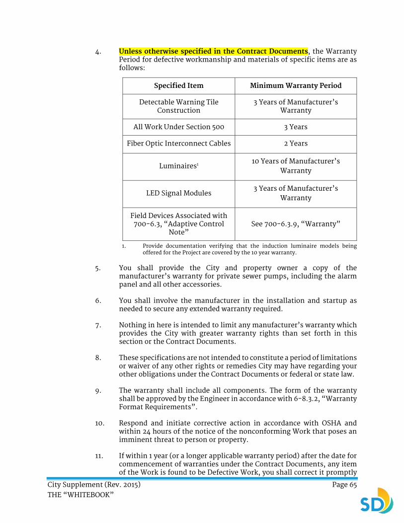
City Supplement (Rev. 2015) Page 65 THE “WHITEBOOK”
4. Unless otherwise specified in the Contract Documents, the Warranty Period for defective workmanship and materials of specific items are as follows:
Specified Item Minimum Warranty Period
Detectable Warning Tile Construction
3 Years of Manufacturer’s Warranty
All Work Under Section 500 3 Years
Fiber Optic Interconnect Cables 2 Years
Luminaires1 10 Years of Manufacturer’s Warranty
LED Signal Modules 3 Years of Manufacturer’s
Warranty
Field Devices Associated with 700-6.3, “Adaptive Control
Note” See 700-6.3.9, “Warranty”
1. Provide documentation verifying that the induction luminaire models being offered for the Project are covered by the 10 year warranty.
5. You shall provide the City and property owner a copy of the manufacturer’s warranty for private sewer pumps, including the alarm panel and all other accessories.
6. You shall involve the manufacturer in the installation and startup as needed to secure any extended warranty required.
7. Nothing in here is intended to limit any manufacturer’s warranty which provides the City with greater warranty rights than set forth in this section or the Contract Documents.
8. These specifications are not intended to constitute a period of limitations or waiver of any other rights or remedies City may have regarding your other obligations under the Contract Documents or federal or state law.
9. The warranty shall include all components. The form of the warranty shall be approved by the Engineer in accordance with 6-8.3.2, “Warranty Format Requirements”.
10. Respond and initiate corrective action in accordance with OSHA and within 24 hours of the notice of the nonconforming Work that poses an imminent threat to person or property.
11. If within 1 year (or a longer applicable warranty period) after the date for commencement of warranties under the Contract Documents, any item of the Work is found to be Defective Work, you shall correct it promptly

City Supplement (Rev. 2015) Page 66 THE “WHITEBOOK”
after receipt of written notice from the City to do so. This period of 1 year (or a longer applicable warranty period) shall be extended with respect to portions of the Work corrected as part of the warranty requirements.
ADD:
6-8.3.1 Defective Work.
1. If the Engineer finds any part of the Work, to be defective or not in compliance with the Contract Documents, you shall correct the Defective Work in accordance with the Engineer’s written instructions and within the specified time limits.
2. The Engineer may order you to stop all or part of the Project if, upon notice, you fail to immediately correct the Defective Work in conformance with the Contract Documents. You bear all direct and indirect costs and damages that result from the City’s Stop Work notice.
3. The Engineer may determine in its sole discretion to accept Defective Work in lieu of requiring you to correct or remove and replace the Defective Work. However, you shall bear all direct and indirect costs of the Defective Work, and the diminished value to the Project, as determined by the Engineer. The Engineer shall issue a Change Order incorporating the necessary revisions in the Contract Documents with respect to the Defective Work and affording the City the appropriate decrease in the Contract Price.
4. If you fail to correct, remove, or replace Defective Work within 5 Working Days from the date of written notice from the Engineer, the Engineer may proceed expeditiously with any correction of Defective Work undertaken in accordance with this section. The City may remedy the Defective Work at a sooner time in the event of an emergency. The City may remedy after 5 Working Days from the date of written notice when you fail to correct the Defective Work in accordance with the Contract Documents or when you fail to comply with any other provision of the Contract Documents. You shall bear all direct and indirect costs of the Defective Work that the City remedies.
5. When undertaking remedial action under this section, the City may exclude you from all or part of the Site, take possession of all or part of the Work and suspend your Work and or Services, and incorporate into the Project all materials and equipment stored at the Site or for which the City has paid but you have stored elsewhere.
6. For Building Projects which require a certificate of occupancy, not including sewer and water facilities, if you fail to correct the defective Work listed on the City’s Punchlist within 30 Days after the Contract Time, you shall reimburse the City for all costs to provide inspection services required to monitor Work beyond the 30 Days, unless specified otherwise. The City shall bill you for the additional inspection at the City’s established rates.
7. If you complete the Project or portions of the Project prior to NOC, you shall preserve equipment by developing and implementing a preventive maintenance program in compliance with manufacturer's recommendations.

City Supplement (Rev. 2015) Page 67 THE “WHITEBOOK”
ADD:
6-8.3.2 Warranty Format Requirements.
1. Written warranties, except manufacturer's standard printed warranties, shall be on yours and your agents’, material suppliers’, installers’, or manufacturers’ own letterhead, addressed to and for the City’s benefit. Submit warranties in the format described in this section, modified as approved by Engineer to suit the conditions pertaining to the warranty.
2. Obtain warranties, executed in triplicate by responsible Subcontractors and Suppliers, within 10 Working Days after completion of the applicable item of Work. Except for items put into use with the Engineer’s permission with date mutually agreed upon in writing, ensure that the beginning time of the warranty is the project completion date.
3. Verify that the documents are in proper form, contain full information, and are notarized.
4. Verify that warranties are signed by both you and the appropriate agent.
5. Retain warranties until the time specified for submittal to the Engineer.
6. Provide warranties to the Engineer with a neatly typed table of contents, identifying each warranty with the number and title of the applicable specification section requiring the warranty and the name of the product or Work item.
7. Separate each warranty with index tab sheets keyed to the table of contents listing. Provide complete information using separate typed sheets as necessary. The information shall include a list of Subcontractors and Suppliers with the name, address, and telephone number of the responsible principals.
ADD:
6-8.3.3 Long-Term Warranty Contract (LTWC).
1. If specified in the Special Provisions and when a LTWC is included in the Contract Documents as an attachment, you shall execute and submit the supplemental agreement for the extended Project warranty (the LTWC covering the workmanship and materials).
2. The first 3 years of warranty protection after installation shall be secured by the faithful performance and payment bonds in accordance with 2-4, “Contract Bonds”.
3. At the conclusion of the initial 3 year bonded warranty period, an “n”-year subsequent manufacturer’s warranty for labor and materials shall commence and run concurrently with the LTWC, where “n” is the number of additional years beyond the initial 3 years as specified in the SSP. Alternatively and with respect to the 3 year bonded warranty, you may submit a 2-year bond followed by 1-year bond. If the alternate option is selected, the 1-year bond shall be submitted to the City at least 90 Days before the expiration of the original 2-year bond. You shall clearly inform the Contract Specialist of the option selected. The protection provided shall not be for less than 3 + “n” years continuously.

City Supplement (Rev. 2015) Page 68 THE “WHITEBOOK”
4. The manufacturer’s warranty for parts and labor shall secure performance of the LTWC by you. Additional security in the form of bonds for both the LTWC and the manufacturer’s extended “n”-year warranty (in years 4 and on following Acceptance) for labor and materials may, but is not required to be, provided per the compensation provisions of the LTWC.
5. The manufacturer warranty shall extend to performance of the LTWC by you, including without limitation the performance of periodic inspections, preparation of periodic reports, and performance of repairs or replacements including parts and labor. If the manufacturer warranty does not expressly extend to the LTWC or is qualified in any way to exclude warranty of the performance of the LTWC by you, the surety bond shall be provided for the LTWC in accordance with 2-4, “Contract Bonds”.
6. If you are unable to obtain a bond which extends the “n”-year term of the LTWC, to obtain a manufacturer warranty or both which clearly and unambiguously extends to secure performance of the LTWC by you for the “n”-year term, the City shall accept either form of security provided that at least one of these forms is provided before award.
7. Provision of the manufacturer’s warranty, bonds, or both as specified is a pre-condition to award of the Contract.
8. Refer to the LTWC for additional information. The provisions of 2-3, “Subcontracts” shall not apply to LTWC.
6-9 LIQUIDATED DAMAGES. DELETE in its entirety and SUBSTITUTE with the following:
1. Your failure to complete the Work within the time allowed shall result in damages being sustained by the City. Such damages are, and shall continue to be, impracticable and extremely difficult to determine. For each consecutive Day in excess of the time specified for the completion of the Work, as adjusted in accordance with 6-6, “Delays and Extensions of Time”, you shall pay to the City, or have withheld from monies due it, the sum described in the table below, unless otherwise specified in the Special Provisions.
2. The execution of the Contract shall constitute agreement between you the City that the liquidated damage amount described in the table below is the minimum value of the costs and actual damage caused by your failure to complete the Work within the allotted time. Such sum shall not be construed as a penalty and may be deducted from your payments if such delay occurs.
Contract Value Liquidated Damage Daily Amount
Less than $100,000 $250
$100,000 and more $1000

City Supplement (Rev. 2015) Page 69 THE “WHITEBOOK”
ADD:
6-11 RIGHT TO AUDIT.
6-11.1 General.
1. The City retains the right to review, audit, reasonably access your and all your Subcontractor’s premises to review and audit your compliance with the provisions of the Contract. This includes the right to inspect, photocopy, and retain copies, outside of your premises, of any and all records with appropriate safeguards if such retention is deemed necessary by the City in its sole discretion. The City will keep this information in strictest confidence.
2. You shall include the right to audit in the subcontracts and ensure that these specifications are binding upon all Subcontractors.
6-11.2 Audit.
1. The right to audit includes the right to examine any and all books, records, documents, and any other evidence of procedures and practices that the City determines is necessary to discover and verify that you are in compliance with all requirements under the Contract.
2. If there is a claim for additional compensation or for changes in Work, the right to audit also includes the right to verify all direct and indirect costs which are claimed to have been incurred, anticipated to be incurred, or for which a claim for additional compensation or for changes in the Work have been submitted.
3. You shall maintain complete and accurate records in accordance with generally accepted accounting practices in the construction industry. Make available to the Engineer for review and audit all Project related accounting records and documents and any other financial data. Upon the Engineer’s request, you shall submit exact duplicates of originals of all requested records to the Engineer.
6-11.3 Compliance Required Before Mediation and Litigation.
1. As a condition precedent to proceeding with mandatory mediation and further litigation under 3-5.2, “Dispute Resolution Process” you shall comply with the audit specifications within 60 Days of the Engineer’s notice to review and audit compliance. See 2-12, “Special Notices”.
6-11.4.1 Access to Records on Federally Funded Projects.
1. You shall retain all records, books, papers, and documents directly pertinent to the Contract for a minimum of 5 years after the City makes final payments and all other pending matters are closed and shall allow access to those records to the City, the Federal grantor agency, the Comptroller General of the United States, or any duly authorized representatives.
City Supplement (Rev. 2015) Page 70 THE “WHITEBOOK”
SECTION 7 - RESPONSIBILITIES OF THE CONTRACTOR
7-1.2 Temporary Utility Services. ADD the following:
1. You shall provide and pay for all electrical, gas, and water required for construction and maintenance activities until Acceptance.
ADD:
7-1.2.1 Water for Construction Purposes.
1. Purchase all water for construction such as water used for initial filling and final flushing of new pipeline, Site maintenance, and maintenance of the vegetation and landscaping items of the Work.
2. Use only the 2.5 inch (63.5 mm) fire hydrant port.
3. Obtain a meter and comply with the Fire Hydrant Meter Policy, Water Department Instruction, DI #55.27, dated April 21, 2000, and attached to the Contract as an appendix. Violation of the requirements as set forth in the DI above shall be subject to fines or penalties pursuant to the City municipal code, §§67.15 and 67.37.
ADD:
7-1.2.2 Payment.
1. Providing and paying for all electrical, gas, and water required for construction and maintenance activities until Acceptance shall be included in the Contract Price.
7-2.2 Prevailing Wages. To Sentence (3), DELETE in its entirety and SUBSTITUTE with the following:
Pursuant to Sections 1771 and 1774 of the Labor Code, you and any Subcontractors shall pay not less than the specified prevailing rates of wages to workers employed on the Contract.
7-2.3 Payroll Records. ADD the following:
1. Your attention is directed to the City of San Diego Labor Compliance Program, Section IV, pages 4-7, and the State of California Labor Code §§1771.5(b) and 1776 (Stats. 1978, Ch. 1249). These require, in part, that you and your Subcontractors maintain and furnish to the City, at a designated time, a certified copy of each weekly payroll containing a statement of compliance signed under penalty of perjury.
2. You and your Subcontractors shall submit weekly certified payrolls reflecting the wages of all yours and Subcontractors’ employees engaged in the Work online via Prism®, the City’s web-based labor compliance program, as specified under 2-16, “CONTRACTOR REGISTRATION AND ELECTRONIC REPORTING SYSTEM”.
City Supplement (Rev. 2015) Page 71 THE “WHITEBOOK”
7-5 PERMITS. DELETE in its entirety and SUBSTITUTE with the following:
7-5 PERMITS, FEES, AND NOTICES.
1. You shall obtain and pay for all business taxes, permits, and fees required for constructing the Project and licenses and inspections necessary for the proper execution and completion of the Work unless specified otherwise in the Contract Documents.
a) To the extent that there is a change in the type or cost of any of such permits, fees, licenses, or inspection occurring after Award of Contract, there shall be an equitable adjustment in the Contract Price on account of such change under the Extra Work provisions.
b) You shall comply with and give notices required by applicable laws. You are not entitled to damages or additional payment for delays attributable to the acquisition of permits.
c) You shall pay the City for regulatory fees, fines, or penalties imposed on the City arising from your failure to complete the Work in accordance with the Contract Documents.
7-5.1 Building Permits.
1. You shall obtain the required building permits from DSD. Any prior approval obtained for the Plans shall not in any way waive this requirement.
2. Request inspections in accordance with the building codes in effect on the permitted plans and by DSD. Any Work performed without the benefit of the required permit and subsequent inspection shall be removed and replaced at the discretion of the City Building Inspector at no additional cost.
7-5.2 Caltrans Encroachment Permit.
1. The City has applied for the Caltrans Encroachment Permit, unless specified otherwise in the Special Provisions.
2. Pay for and secure the permit prior to construction regardless of which party has applied for it.
3. Arrange and pay for inspection as required by Caltrans.
4. You are solely responsible for permit processing delays that result from incomplete or inaccurate information provided by you to the City or Caltrans.

City Supplement (Rev. 2015) Page 72 THE “WHITEBOOK”
7-5.3 Payment.
1. The payment for Permits shall be included in the Contract Price unless an Allowance Bid item has been provided.
2. When applicable, an Allowance Bid item has been provided for the “Caltrans Encroachment Permit”.
ADD:
7-6.1 Project Meetings.
1. Your project team shall attend scheduled construction meetings as required by the Engineer. If any of your staff cannot attend, you shall notify the Engineer a minimum of 24 hours in advance, prior to the start of the scheduled meeting. If you do not provide the required notification, you shall pay for the costs of the City’s staff, Consultants, or both that attended. You shall be charged a minimum of 2 hours of the attendee’s time.
7-6.1.1 Payment.
1. The payment for your attendance to Project meetings is included in the Contract Price. The Engineer shall deduct costs assessed to you for not attending the meetings from the monthly progress payment via Change Order.
7-8.1 General. ADD the following:
1. Maintain Site improvements, including any temporary facilities, equipment, or other materials free of graffiti. Remove graffiti encountered on the Site within 24 hours.
ADD:
7-8.1.1 Affidavit of Legal Disposal.
1. As a condition of Final Payment, you shall submit a signed and notarized affidavit stating that all brush, trash, debris, and surplus materials resulting from this Project have been disposed of in a legal manner. See the Affidavit of Disposal in the Contract Documents. Disposal of refuse generated as a result of the Contract at the City landfills shall be subject to a fee. Contact the Refuse Disposal Division at (858) 573-1418 for fee information.
ADD:
7-8.1.2 Sanitation.
1. If required in the Special Provisions, provide and maintain enclosed toilets for the use of the City’s and your officers, employees, or agents. Keep these accommodations in a neat and sanitary condition and ensure that they comply with all applicable laws, ordinances, and regulations pertaining to public health and sanitation of dwellings and camps.

City Supplement (Rev. 2015) Page 73 THE “WHITEBOOK”
ADD:
7-8.2.1 Dust Abatement.
1. You shall carry out effective measures whenever and as often as necessary to prevent its operation from producing dust in amounts damaging to property, cultivated vegetation, domestic animals, or causing a nuisance to persons living or occupying buildings in the vicinity. You shall be responsible for any damage resulting from any dust originating from its operations. The dust abatement measures shall be continued until you are relieved of further responsibility by the Engineer.
7-8.4.1 General. ADD the following:
1. Equipment and material storage shall be confined to areas approved by the Engineer. Disposal of all rubbish and surplus materials shall be at your expense. Disposal shall be made off the Site and shall be in accordance with:
a) Local codes and ordinances that govern locations and methods of disposal.
b) All applicable safety laws.
c) Requirements of Subpart H, §1926.252 of the OSHA Safety and Health Standards for Construction.
ADD:
7-8.4.3 Storage and Staging Areas.
1. If the Plans designate a staging location within the Project or in close proximity, utilize such area for their use. Otherwise, storage and staging areas are your responsibility. The storage and staging areas shall be as close as possible to the Site. You are responsible for obtaining any permits, leases, or any other items necessary to obtain staging areas.
2. Storage of hazardous wastes, construction equipment material, and parking and fueling of equipment shall not be allowed in the MHPA or other biologically sensitive areas. Ensure the fueling of vehicles occurs only within designated staging areas using appropriate catch basins and devices.
3. Return the storage and staging area and the adjacent area to an equal or better condition as deemed necessary by the Engineer, at no additional cost to the City.
ADD:
7-8.4.4 Payment.
1. The payment for Work Site maintenance, as described in 7-8.1, “General” through 7-8.4, “Storage of Equipment and Materials” shall be included in the Bid item for “Mobilization”. If a Bid item for “Mobilization” has not been provided, the payment shall be included in the Contract Price.

City Supplement (Rev. 2015) Page 74 THE “WHITEBOOK”
2. Disposal of refuse generated as a result of the Contract at the City landfills as described in 7-8.1.1, “Affidavit of Legal Disposal” shall include all fees and shall be included in the Contract Price.
7-8.5.1 General. ADD the following:
1. You shall observe and comply with the City’s policy of zero spills. You shall be liable for all damages sustained by the City that result from sewage spills caused by your actions.
2. You shall designate a person responsible for the development and enforcement of the Spill Prevention and Emergency Response Plan, and for ensuring sewer spills are minimized to the maximum extent possible. You shall provide a status of all bypass related Work at biweekly progress meetings as requested by the City.
7-8.5.2 Sewage Bypass and Pumping Plan. ADD the following:
1. You shall submit to the Engineer for approval, a Sewage Bypass and Pumping Plan at least 15 Working Days prior to the implementation of flow diversion in compliance with the City’s policy of “Zero Spills”. The Sewage Bypass and Pumping Plan shall indicate the sequence of diversion operations, all other operations that you shall establish to maintain wastewater service during the construction period, and a quality assurance and quality control plan for the diversion Work. The Sewage Bypass and Pumping Plan shall include an emergency response plan indicating the procedures, equipment, and activities that shall be implemented in the event of an emergency shutdown or failure of the flow diversion equipment used for construction. You shall be responsible for the implementation of the emergency plan in accordance with 7-8.5.3, “Spill Prevention and Emergency Response Plan”.
2. Your Sewage Bypass and Pumping Plan shall be reviewed and approved by the Wastewater Collection Division of the City before flow can be diverted. No deviation from the approved Sewage Bypass and Pumping Plan shall be allowed without prior approval from the Engineer.
3. You shall be fully responsible for preventing, containing, recovering, and legally disposing sewage spills. This shall include any fines, penalties, claims, and liabilities arising from negligently causing a sewage spill and any violation of any law, ordinance, code, order, or regulation as a result of the spill.
4. You shall exercise care not to damage existing public and private improvements and not to interrupt existing services or facility operations which may cause sewage spills. Any reasonably anticipated utility or improvement which is damaged by your actions shall be immediately repaired at your expense. In the event that you damage an existing utility or interrupt an existing service which causes a sewage spill, immediately call the emergency number at (619) 515-3525.
5. You shall provide all facilities, labor, power, and appurtenances necessary to divert wastewater flows as necessary to allow proper installation of the pipeline and/or manhole linings.

City Supplement (Rev. 2015) Page 75 THE “WHITEBOOK”
6. You shall submit as part of your Sewage Bypass and Pumping Plan the monitoring procedure and frequency and shall continuously monitor the flow levels downstream and upstream of the flow diversion to detect any possible failure that may cause a sewage backup and spills. You shall maintain a log of the monitoring and provide daily copies to the Engineer in a manner acceptable to the Engineer.
7. You shall inspect and maintain the diversion system daily, including the back-up system. You shall submit with your Sewage Bypass and Pumping Plan the maintenance procedures and frequency. You shall maintain a log of all inspection, maintenance, and repair records and shall provide copies to the Engineer upon request in a manner acceptable to the Engineer.
8. You shall size the flow diversion system to handle the peak flow and shall include a 100% backup in the flow diversion system. You shall provide temporary means to maintain and handle the sewage flow in the existing system as required to complete the necessary construction. You shall utilize the flow diversion system to mitigate any additional wet weather flows, perform the necessary maintenance and repairs on the flow diversion system, and exercise and ensure the operation of the backup system. Each pump, including the backup pumps, shall be a complete unit with its own suction and discharge piping.
9. You shall operate the backup flow diversion system for a minimum of 25% of the total diversion time on a weekly basis. The backup flow diversion system shall be fully installed, operational, and ready for immediate use. The diversion system shall be hydraulically tested with clean water prior to wastewater flow diversion. You shall demonstrate to the satisfaction of the Engineer that both the primary and backup flow diversion systems are fully functional and adequate and shall certify the same in writing to the Engineer in a manner acceptable to the Engineer.
10. If fuel or generator driven pumps are used, you shall provide one dedicated fuel tank for every single pump or generator. You shall provide an emergency standby power generator if electric power driven pumps are used. You shall provide a fuel level indicator outside each fuel tank. While in use, continuously monitor the fuel level in the tanks and ensure that the fuel level does not drop below a level equivalent of 2 hours of continuous flow diversion system operation. You shall take the necessary measures to ensure that the fuel supply is protected against contamination. This includes but is not limited to fuel line water traps, fuel line filters, and protecting fuel stores from precipitation. You shall monitor all hoses and repair leaks immediately.
7-8.5.3 Spill Prevention and Emergency Response Plan.
1. Prior to the start of construction, you shall develop and submit to the Engineer for review and approval, a written Spill Prevention and Emergency Response Plan. The plan shall include a sewage spill response plan, spill containment and cleanup plan, staging area, and sewage bypass and pumping plan.
City Supplement (Rev. 2015) Page 76 THE “WHITEBOOK”
2. The Spill Prevention and Response Plan shall be developed to respond to any construction related sewage spills. The plan shall include:
a) Identifying all nearby environmentally-sensitive areas such as waterways, channels, catch basins, and entrances to existing underground storm drains.
b) Making arrangements for an emergency response unit stationed at or near the Site that is comprised of emergency response equipment and trained personnel to be immediately dispatched in the event of a sewage spill. If in an environmentally-sensitive area such as a canyon, this shall include field biologists, archaeologists, or both.
c) An emergency notification procedure that includes an emergency response team with telephone numbers and arrangements for backup personnel and equipment. The emergency response unit shall be able to dispatch to the Site 24 hours a day 7 days a week including weekends and Holidays. You shall designate primary and secondary representatives by their respective phone numbers, pager numbers, and mobile phone numbers. Your representatives shall be accessible and available at all times to respond immediately to any sewer spill event.
d) Identifying any property owners who may be affected such as the City Park and Recreation Department.
3. At the Pre-construction meeting you shall be provided with a list of the City representatives to contact in case of sewage spills. In case of a sewage spills, you shall immediately call the Sewage Spill Hotline number at (619) 527-5481 and shall act immediately without instructions from the City, to control the spill and take all appropriate steps to contain it in accordance with the 7-8.5.3 “Spill Prevention and Emergency Response Plan” and 7-8.5.2, “Sewage Bypass and Pumping Plan”. You shall immediately notify the City representatives of the spill and shall report the Project name, location, Contractor name, Project Engineer name, and the Engineer name.
4. Within 3 Working Days from the occurrence of the spill, submit to the Engineer a written report describing the following information related to the spill: the location, the nature and estimated volume, the date and time, the duration, the cause, the type of remedial and/or clean up measures taken (including erosion control measures), the date and time of implementation, the corrective and/or preventive actions taken to avoid further spills, the equipment used in the spill response, and the environmentally-sensitive habitat, such as a water body, if any, that has been impacted and the results of any necessary monitoring. You shall provide a list of names from the City of which whom were notified, the date and time of notification, the date and time you were notified of the spill, and the date and time you arrived on Site.

City Supplement (Rev. 2015) Page 77 THE “WHITEBOOK”
5. The Engineer may institute further corrective actions, as deemed necessary, to fully comply with existing laws, ordinances, codes, orders, or other pertinent regulations. In addition to any penalties provided by federal, state, and local laws, you shall be responsible for all costs incurred for the corrective actions including mitigation measures (habitat restoration and etc.) and obtaining after-the-fact permits, if necessary, in environmentally sensitive areas. These permits include but are not limited to those from the City Planning Department Development Services, California Coastal Commission, U.S. Army Corps of Engineers, and the California Department of Fish and Game.
6. It shall be your responsibility to ensure that all field forces, including Subcontractors, know and obey all safety and emergency procedures, including the Spill Prevention and Emergency Response Plan applicable to the Work to be maintained and followed at the Site. Impacts shall be minimized if the Site is in an environmentally sensitive area, such as canyons, streams, or lagoons. Crews shall be aware at the start of the job of any sensitive environmental habitats, breeding season restrictions, and etc.
7. You shall prevent spills when working on sewer lines, such as when making temporary connections and when connecting new lines into the sewer system, and shall ensure that no laterals are connected to mains being abandoned. Ensure that diversions are appropriately installed and that diversions are completely removed when finished so there are no blockages. You shall not trap debris and discharge rock or debris downstream. Avoidance of streams is paramount, unless authorized via permits.
8. You shall defend, indemnify, protect, and hold harmless the City, its agents, officers, and employees, from and against all claims asserted or liability established for damages or injuries to any person or property resulting from any sewage spill caused or claimed to be caused by your action or failure to take measures to prevent a spill. You shall be responsible for the payment of any fines assessed against the City for such sewage spills. Your duty to indemnify and hold harmless shall not include any claims or liability arising from the established active or sole negligence or willful misconduct of the City, its agents, officers or employees.
9. You shall obtain and maintain an additional insurance coverage for Pollution Liability with its limits and requirements as set forth in 7-3.5.3, “Contractors Pollution Liability Insurance Endorsements”. The limits and requirements for Pollution Liability shall be in an amount sufficient to cover potential losses from sudden and accidental pollution.
ADD:
7-8.5.4 Payment.
1. Unless a Bid item has been provided for “Sewage Bypass and Pumping Plan (Diversion Plan)”, full compensation for the Sewage Bypass and Pumping Plan and its implementation including labor, facilities, equipment, power, appurtenances, and all incidental Work shall be included in the payment for the sewer main.

City Supplement (Rev. 2015) Page 78 THE “WHITEBOOK”
2. Full compensation for the spill prevention and emergency response plan and its implementation including labor, facilities, equipment, power, appurtenances, and all incidental Work shall be included in the Contract Price.
7-8.6 Water Pollution Control. ADD the following:
1. The Project is subject to the Storm Water Pollution control requirements listed on the Plans or as specified in the SSP.
2. For contracts subject to the Construction General Permit (CGP), your QSD shall verify the City’s assessment prior to Bid submittal.
3. These specifications set the City’s minimum requirements. You shall comply with the requirements of the City’s Storm Water Standards Manual, Municipal Permit, and Construction General Permit for any construction or demolition activity that results in a land disturbance.
4. You shall pay the City for regulatory or court imposed fees, fines, or penalties imposed on the City arising from your failure to complete the Work in compliance with the requirements of the City’s Storm Water Standards Manual, Municipal Permit, and CGP.
5. You shall be responsible for delays associated with your failure to complete the Work in compliance with the requirements of the City’s Storm Water Standards Manual, Municipal Permit, and CGP.
7-8.6.1 General. DELETE in its entirety and SUBSTITUTE with the following:
1. Conform to all applicable local, state, and Federal regulations and laws pertaining to water pollution control. You shall conduct and schedule its operations and follow and implement best management practices in such a manner as to prevent water pollution.
ADD:
7-8.6.1.1 Terms, Definitions, and Acronyms.
1. The terms, definitions, and acronyms listed in Appendices 5 and 6 of the CGP shall apply except as follows:
a) Attachments - Attachments referenced in these specifications are from the CGP. Attachments can be viewed at the following website:
http://www.swrcb.ca.gov/water_issues/programs/stormwater/constpermits.shtml
b) Best Management Practice (BMP) –
i. A method that is implemented to protect water quality and prevent or reduce the potential for pollution associated with storm water runoff and construction activities. Examples include scheduling of activities, prohibitions of practices, maintenance procedures, and other management practices.
ii. Any program, process, siting criteria, technology, treatment requirement, or operating method, measure, or
City Supplement (Rev. 2015) Page 79 THE “WHITEBOOK”
device that controls, prevents, removes, or reduces pollution.
c) Construction General Permit (CGP) - National Pollutant Discharge Elimination System permit for Storm Water Discharges associated with the construction and land disturbance activities (State Water Resources Control Board Permit, Order No. 2009-0009 DWQ).
d) Discharger - The Contractor (You).
e) Legally Responsible Person (LRP) - The City of San Diego for the City’s Public Works projects.
f) Linear Utility/Overhead Project (LUP) - LUPs include the following:
i. Any conveyance, pipe, or pipeline for the transportation of any gaseous liquid including water, wastewater for domestic municipal services, liquescent, or slurry substances.
ii. Any cable line or wire for the transmission of electrical energy.
iii. Any cable line or wire for communications such as telephones, telegraphs, radios or television messages.
iv. Associated ancillary facilities.
g) Maximum Extent Practicable (MEP) - The technology-based standard established by the United States Congress in the Clean Water Act 402(p)(3)(B)(iii) that municipal discharges of urban runoff shall meet. MEP generally emphasizes pollution prevention and source control BMPs primarily as the first line of defense in combination with treatment methods serving as backup and additional lines of defense.
h) Municipal Permit - Municipal storm water permit for San Diego region. Order Number R9-2013-0001 and all other subsequent amendments.
i) Numeric Effluent Limitation (NEL) - Any numeric or narrative restriction imposed on quantities, discharge rates, and concentrations of pollutants, which are discharged from point sources into waters of the United States, the waters of the contiguous zone, or the ocean. The CGP contains both narrative Effluent limitations and numeric Effluent limitations for pH and Turbidity.
j) Permit Registration Documents (PRD) - Includes a Notice of Intent (NOI), Risk Assessment, Site Map, Storm Water Pollution Prevention Plan (SWPPP), Annual Fee, and a signed Certification Statement.
k) Qualified Contact Person (QCP) - The trained and competent person you employ that shall be responsible for the implementation of a WPCP.

City Supplement (Rev. 2015) Page 80 THE “WHITEBOOK”
l) Rainfall Erosivity Waiver - For projects subject to the CGP, the EPA’s Small Construction Erosivity Waiver applies to sites between one and five acres demonstrating that there are no adverse water quality impacts. Projects which qualify for a Rainfall Erosivity Waiver shall submit a WPCP in lieu of a SWPPP as part of the PRDs.
m) Rain Event Action Plan (REAP) - A Rain Event Action Plan (REAP) is a written document, specific for each rain event. A REAP should be designed that when implemented it protects all exposed portions of the site within 48 hours of any likely precipitation event forecast of 50% or greater probability. The CGP requires Risk Level 2 and 3 dischargers to develop and implement a REAP designed to protect all exposed portions of their sites within 48 hours prior to any likely precipitation event. The REAP requirement is designed to ensure that the discharger has adequate materials, staff, and time to implement erosion and sediment control measures that are intended to reduce the amount of sediment and other pollutants generated from the active site. A REAP shall be developed when there is likely a forecast of 50% or greater probability of precipitation in the project area.
n) Storm Water Multiple Application and Report Tracking System (SMARTS) - The Storm Water program regulates storm water discharges from locations such as industrial facilities, construction sites, and small linear projects. SMARTS is also responsible for processing, reviewing, updating, terminating Notices of Intent (NOIs), annual reports, and maintaining the billing status of each discharger. SMARTS has been developed to provide an online tool to assist dischargers in submitting their NOIs, NOTs, and Annual Reports, as well as, viewing/printing Receipt Letters, monitoring the status of submitted documents, and viewing their application/renewal fee statements. The system shall also allow the Regional Board and State Board staff to process and track the discharger’s submitted documents. SMARTS is a user account and password protected system where a valid user account and password is needed to access the system.
o) Storm Water Pollution Prevention Plan (SWPPP) - Site specific document required by the CGP and Municipal Permit.
p) Water Pollution Control Plan (WPCP) - A plan required by the City Storm Water Standards Manual for projects with less than 1 acre of ground disturbance, inclusive of any unpaved areas associated with the Project or for projects which exceed an acre and qualify for a Rainfall Erosivity Waiver, which is determined to have a potential to impact water quality during construction.
q) Water Quality Sensitive Area - Areas that include, but are not limited to, all Clean Water Act 303(d) impaired water bodies (“303[d] water bodies”); areas designated as an “Area of Special Biological Significance” (ASBS) by the State Water Resources Control Board (Water Quality Control Plan for the San Diego Basin

City Supplement (Rev. 2015) Page 81 THE “WHITEBOOK”
(1994) and amendments); water bodies designated as having a RARE beneficial use by the State Water Resources Control Board (Water Quality Control Plan for the San Diego Basin (1994) and amendments), or areas designated as preserves or their equivalent under the Multiple Species Conservation Program (MSCP) within the Cities and County of San Diego. The limits of ASBS are those defined in the Water Quality Control Plan for the San Diego Basin (1994 and amendments). The City of San Diego has identified the Los Penasquitos Lagoon as an impaired water body (CWA 303(d)) for sediment. The City of San Diego has two (2) areas of ASBS, La Jolla (#29) and San Diego-Scripps (#31).
r) WDID # - Waste Discharge Identification number required prior to the start of any construction activities for projects that disturb more than one acre.
ADD:
7-8.6.1.2 Illegal Discharges.
1. Any discharge to the MS4 that is not composed entirely of storm water except discharges allowed under an NPDES permit and discharges conditionally allowed under the MS4 permit, as set forth in San Diego Municipal Code section 43.0305. Illicit discharges include irrigation runoff discharged to the MS4.
ADD:
7-8.6.1.3 Additional Control Requirements for Areas of Special Biological Significance.
1. These are ocean areas requiring protection of species or biological communities to the extent that alteration of natural water quality is undesirable and are classified as a subset of State Water Quality Protection Areas. For construction sites located within the La Jolla Shores sub-watershed, non-storm water discharges are prohibited from entering the City’s storm water conveyance system, including, but shall not be limited to, natural drainages, ditches, roads, streets, constructed channels, aqueducts, storm drains, pipes, street gutters, or catch basins. The method for the removal and disposal of non-storm water discharges shall be included with detail in the WPCP or SWPPP.
ADD:
7-8.6.1.4 Training.
1. You shall ensure that all persons responsible for compliance with the San Diego Municipal Code Section §43.03, City’s Storm Water Standards Manual, Municipal Permit, and CGP shall be appropriately trained in accordance with the CGP. Training shall be both formal and informal, occur on an ongoing basis, and shall include training offered by recognized governmental agencies or professional organizations. You shall include documentation of all training to the Engineer and as required by the Annual Report.
City Supplement (Rev. 2015) Page 82 THE “WHITEBOOK”
ADD:
7-8.6.1.5 Legally Responsible Person (LRP).
1. For projects with coverage under the CGP the City has identified the LRP for the regulated Site and designated at least one Approved Signatory (AS) in the event that the LRP is unavailable. Only the LRP or the AS may certify the final submittal of the PRDs, Annual Reports, SWPPP Amendments, and Notice of Termination using SMARTS.
ADD:
7-8.6.1.6 Qualified SWPPP Developer (QSD).
1. For projects subject to the CGP, you shall appoint a QSD to prepare the SWPPP with site specific BMPs and pertinent information in accordance with the CGP prior to uploading onto SMARTS. The verification of the certification shall be included in the SWPPP.
2. The QSD shall have the certification and appropriate experience as required for in the CGP Section VII.B.1.
ADD:
7-8.6.1.7 Qualified SWPPP Practitioner (QSP).
1. For projects subject to the CGP, you shall appoint a QSP. The QSP shall be responsible for non-storm water and storm water visual observations, sampling and analysis, the preparation of the annual compliance evaluation, and the elimination of unauthorized discharges. The QSP shall be on-Site daily to evaluate the conditions of the Site with respect to storm water pollution prevention.
2. The QSP shall have one of the certifications and appropriate experiences as required for in the CGP Section VII.B.3.
ADD:
7-8.6.1.8 Permit Registration Documents (PRDs).
1. For projects subject to the CGP, you shall prepare and upload the PRDs into SMARTS. The PRDs shall be reviewed, certified, and filed by the LRP or designee following the review of your submittal. You shall submit the PRD’s to the Engineer for review at or prior to the Pre-construction Meeting. The Contract Time shall start in accordance with 6-1.2, “Commencement of the Work” or as determined by the Engineer. The Work shall not commence without a valid WDID number.
2. The City shall initiate the NOI form application process and set up the project in SMARTS. You shall complete the Developer, Risk Assessment, Billing Information, and Additional Site Info tabs in SMARTS. The LRP/AS shall certify the NOI application.
3. A preliminary Risk Assessment has been calculated for design purposes based on the Site’s characteristics and the CGP requirements. You shall perform a separate Risk Assessment to verify the City’s Preliminary Risk Assessment. The Risk Assessment shall be completed by the QSD using the Risk Determination Worksheet in Appendix 1 of the CGP.
City Supplement (Rev. 2015) Page 83 THE “WHITEBOOK”
4. You shall prepare the Site map(s) with the PRDs as described in the CGP. As phases of the construction change, the Site Map shall be adjusted to correspond to each phase. A copy of each Site Map shall be included in the SWPPP. At a minimum, the Site Map shall include:
a) The project’s surrounding area (vicinity).
b) Site layout.
c) Construction site boundaries.
d) Drainage areas.
e) Discharge locations.
f) Sampling locations.
g) Areas of soil disturbance (temporary or permanent).
h) Active areas of soil disturbance (cut or fill).
i) Locations of all runoff BMPs.
j) Locations of all erosion control BMPs.
k) Locations of all sediment control BMPs.
l) ATS location (if applicable).
m) Locations of sensitive habitats, watercourses, or other features which are not to be disturbed.
n) Locations of all post-construction BMPs.
o) Locations of storage areas for waste, vehicles, service, loading/unloading of materials, access (entrance/exits) points to construction site, fueling, water storage, water transfer for dust control, and compaction practices.
For LUPs, at least 3 maps shall be submitted. The first map shall be a zoomed 1000 feet - 1500 feet (304.8 m – 457.2 m) vicinity map that shows the starting point of the project. The second map shall be a zoomed map of 1000 feet - 1500 feet (300 m - 450 m) showing the ending location of the project. The third map shall be a larger view vicinity map, 1000 feet - 2000 feet (304.8 m – 609.6 m), displaying the entire project location depending on the project size and indicating the LUP type (1, 2, or 3) areas within the total project footprint.
5. For LUPs only, submit construction drawings that show the locations of storm drain inlets and waterbodies that may receive discharges from the construction activities and that shows the locations of BMPs to be installed.
6. The SWPPP shall be prepared using the guidelines in Appendix G of the City’s Storm Water Standards Manual and in accordance with the requirements of the CGP. CASQA and Caltrans SWPPP Templates are available online electronically and may be used for this purpose. The SWPPP and each amendment shall be prepared and signed by the QSD and shall be submitted to the Engineer for review. If extensive additions or corrections are required, the Engineer shall return the submittal for

City Supplement (Rev. 2015) Page 84 THE “WHITEBOOK”
corrections and re-submission. After the SWPPP is revised to the satisfaction of the Engineer, the SWPPP shall be uploaded through SMARTS. The QSD shall notify the Engineer no later than 24 hours from when the upload is complete.
7. The SWPPP shall be implemented by you and updated as necessary to address Site conditions. Make the SWPPP available at the Site during working hours while construction is occurring and make it available upon request by a State inspector or the Engineer within 1 hour of request.
8. You shall be responsible for paying the required permit fee to the State Water Resources Control Board immediately following the filing of the PRDs by the LRP. The QSD shall notify the Engineer when the payment is mailed to the State Water Board.
9. Once all PRDs are submitted to SMARTS and payment is received by the State Water Board, the LRP shall receive a notification to certify the PRDs. You shall allow for 5 Working Days for Certification by the LRP or AS.
ADD:
7-8.6.1.9 Effluent Standards.
1. For projects subject to the CGP, refer to the CGP for the applicable effluent standards pertinent to Risk Levels 2 and 3 and LUP Types 2 and 3. Site evaluations and testing and sampling results shall be documented in the SWPPP in accordance with requirements of the CGP.
ADD:
7-8.6.1.10 Record Retention.
1. As required in the CGP, you shall submit a completed SWPPP with all inspection reports, annual reports, and updated Site Maps to the Engineer at the completion of the project.
ADD:
7-8.6.1.11 Post-construction Requirements.
1. You shall comply with the post-construction storm water requirements when post-construction requirements have been identified in the Contract Documents.
2. You shall mark every storm drain inlet within the projects boundaries with adhesive decal-discs or imbedded concrete stamps. You shall use decal-discs on existing inlets and concrete stamps on new inlets. On curb inlets, the concrete stamp or decal discs shall be placed on the top of curb at the inlet roof. On catch basins, the concrete stamp shall be imprinted next to the inlet grate.
3. The decal-disc inlet markers shall be “das Duracast Curb Marker®” or approved equal.

City Supplement (Rev. 2015) Page 85 THE “WHITEBOOK”
4. Final site stabilization requirements shall be as follows:
a) The site shall not pose any additional sediment discharge risk than it did prior to the commencement of construction activity.
b) There shall not be any potential for construction-related storm water pollutants to be discharged into site runoff.
c) All final landscaping and hardscaping has been installed.
d) Construction materials and wastes have been disposed of properly.
e) Post-construction storm water management measures have been installed and a long-term maintenance plan has been established.
f) All construction-related equipment, materials, and any temporary BMPs that are no longer needed are removed from the site.
5. For projects subject to the CGP, the QSP shall notify the Engineer immediately if the removal of the construction BMP shall expose the Site to conditions that would impair the water quality and put the City at risk of violations to the CGP and/or Municipal Permits.
ADD: 7-8.6.1.12 Notice of Termination (NOT).
1. For projects subject to the CGP, you shall terminate coverage of a site by uploading an electronic NOT, a final site map, and photos onto SMARTS. The final site map and photos shall be submitted to the Engineer as a submittal for review prior to the upload to SMARTS. By uploading a NOT, you shall be certifying that construction activities are complete and that the Project is in full compliance with the requirements of the CGP. The LRP shall be notified by SMARTS that a NOT was submitted for certification. You shall allow for 5 Working Days for the LRP or AS to certify the NOT. Upon approval by the appropriate Regional Water Board office, permit coverage shall be terminated and communicated to the LRP. Approval of the NOT does not relieve you of the responsibility for the submittal of Annual Reports and the payment of the Annual Fee.
ADD:
7-8.6.1.13 Annual Reports and Annual Fee.
1. For projects subject to the CGP, you are responsible for the submittal of the Annual Reports and for the payment of the Annual fee in accordance with requirements of the CGP. If the Project is enrolled for more than one continuous 3-month period, you shall electronically upload an Annual Report through SMARTS no later than August 1st of each year. SMARTS shall notify the City of submittals and reviews for certification. You shall allow the City 5 Working Days for review. If extensive additions or corrections are required, the Engineer shall notify you of corrections and re-submission. After the Annual Report is revised to the satisfaction of the Engineer, the Annual Report shall be uploaded through SMARTS. You shall allow for 5 Working Days for the LRP or AS to certify the Annual

City Supplement (Rev. 2015) Page 86 THE “WHITEBOOK”
Report. Annual Reports shall be retained on Site and included in the SWPPP while construction is ongoing. The annual reports shall include the following:
a) Storm water monitoring information as listed in Section XVI.D of the CGP.
b) Training information for all individuals responsible for Permit compliance (Section XVI.E).
2. You shall pay the Annual Fee to the State Water Board within 30 Calendar Days of notification by the Engineer. Your failure to pay within this timeframe shall result in a Notice of Violation (NOV) and the forwarding of the invoice to a Collections agency by the State.
ADD: 7-8.6.1.14 Change of Information.
1. For projects subject to the CGP, you are responsible for updating SMARTS to reflect the most current project schedule, to submit revised Site Plans, to reflect changes to types of BMPs, and any changes to the QSD and/or QSP. This includes, but shall not be limited to, changes of information to the Developer, Risk, and Billing Info tabs. At least 5 Days prior to updating SMARTS, you shall notify the Engineer as to the nature of the change(s).
ADD: 7-8.6.1.15 Risk Assessment.
1. For projects subject to the CGP, you shall update the project schedule in the Risk tab of SMARTS monthly to match the schedule provided at the monthly progress meetings. If during construction, the Risk level or LUP type is increased you shall comply with the additional requirements required by the CGP.
ADD:
7-8.6.1.16 Rainfall Erosivity Waiver Expiration.
1. For projects subject to the CGP, 30 Days prior to expiration of the Rainfall Erosivity Waiver, you shall update the project schedule in the Risk Assessment tab of SMARTS. Should the project construction extend beyond the projected completion date given on the waiver certification, you shall recalculate the rainfall erosivity factor for the new project duration and submit this information through the SMARTS system.
2. If the new R factor is below 5, you shall update all applicable information on the waiver certification through SMARTS and retain a copy of the revised waiver onsite.
3. If the new R factor is 5 or above, you shall immediately notify the Engineer. The Engineer shall initiate the NOI application process and set up the project in SMARTS to obtain coverage under the CGP. You shall complete the Developer, Risk, Billing Information, and Additional Site Info tabs in SMARTS. You shall be required to retain a QSP, shall prepare and submit a SWPPP, Site Map, and Drawings (for LUPs), and shall pay the permit fee.

City Supplement (Rev. 2015) Page 87 THE “WHITEBOOK”
4. Should the Rainfall Erosivity Waiver expire prior to obtaining permit coverage (active WDID#), you shall cease all construction Work. No additional payment to you shall be made as a result of the delay in Work.
ADD:
7-8.6.1.17 Risk Levels and LUP Types.
1. You shall refer to the Risk Level or LUP Type identified for the Contract and the following to determine the applicable requirements of the CGP:
a) Risk Levels (Traditional).
i. Risk Level 1 (Baseline for all Risk Levels). See Attachment C of the CGP.
ii. Risk Level 2. See Attachment D of the CGP.
iii. Risk Level 3. See Attachment E of the CGP.
b) LUP Types (Linear Underground/Overhead Projects). See Attachment A of the CGP.
i. Type 1 LUP.
ii. Type 2 LUP.
iii. Type 3 LUP.
ADD:
7-8.6.2.1 Construction BMP.
1. As required by the City’s Storm Water Standards Manual and Municipal Permit, BMPs shall be installed in accordance with California Stormwater Quality Association (CASQA) BMP handbooks:
https://www.casqa.org/
or Caltrans Construction Site BMP Manual:
http://www.dot.ca.gov/hq/construc/stormwater/details.htm
2. You shall store and have readily accessible, sufficient and appropriate standby BMP materials necessary to protect the Site against erosion, to prevent sediment discharge, and to prevent non storm water discharges.
ADD:
7-8.6.2.2 Erosion Control.
1. You shall control the Site erosion through the implementation of effective wind erosion control and effective soil cover for Inactive Areas, all finished slopes, open spaces, utility backfills, and completed lots.
2. Erosion shall be prevented. Erosion-susceptible slopes and denuded areas shall be stabilized, covered, planted, or otherwise protected in a way that prevents displacement.
3. You shall protect unpaved areas, including landscaping, from erosion-using vegetation or other physical stabilization.

City Supplement (Rev. 2015) Page 88 THE “WHITEBOOK”
4. Exposed soils that are actively eroding, or prone to erosion due to disturbance, shall be protected from erosion. Significant accumulations of eroded soil shall be removed or contained to prevent sediment transport in runoff to the storm drain system.
5. Such temporary measures shall be maintained and replaced as needed until such time a permanent solution can be implemented.
6. The SWPPP/WPCP shall include the sequencing of the Work activities and the implementation of effective Erosion Control BMPs while taking local climate, such as rainfall and wind, into consideration thereby reducing the amount and duration of soil exposed to erosion by wind, rain, runoff, and vehicle tracking.
7. The SWPPP/WPCP shall:
a) Describe when Work shall be performed that could cause the discharge of pollutants in storm water.
b) Describe the water pollution control practices associated with each construction phase.
c) Identify the soil stabilization and sediment control practices for all disturbed soil area.
ADD:
7-8.6.2.3 Good Site Management “Housekeeping”.
1. You shall ensure construction-related materials, wastes, spills, or residues are prevented from discharging from the Work Site to streets, drainage facilities, receiving waters, or adjacent properties by wind or runoff.
2. You shall ensure non-storm water runoff from equipment, vehicle washing, or any other activity shall be contained within the Work Site using appropriate BMPs.
3. You shall assess the potential pollutant sources, identify areas of the Site where additional BMPs are necessary, and ensure the effectiveness of existing BMPs.
4. You shall cover and berm loose stockpiled construction materials that are not actively being used (soil, spoils, aggregate, fly-ash, stucco, hydrated lime, and etc.).
5. You shall store chemicals in watertight containers (with appropriate secondary containment to prevent any spillage or leakage) or in a storage shed (completely enclosed).
6. You shall minimize exposure of construction materials to precipitation.
This does not include materials and equipment that are designed to be outdoors and exposed to environmental conditions (poles, equipment pads, cabinets, conductors, insulators, bricks, and etc.).
7. You shall implement BMPs to prevent the offsite tracking of loose
construction and landscape materials.

City Supplement (Rev. 2015) Page 89 THE “WHITEBOOK”
8. You shall prevent the disposal of any rinsed or washed waters or materials on impervious or pervious site surfaces or into the storm drain system.
9. You shall ensure that the containment of sanitation facilities, such as portable toilets, prevent discharges of pollutants to the storm water drainage system or receiving water.
10. You shall clean or replace sanitation facilities and inspect them regularly for leaks and spills.
11. You shall cover waste disposal containers at the end of every business day and during a rain event.
12. You shall prevent waste disposal containers from discharging to the storm water drainage system or to receiving water.
13. You shall contain and securely protect stockpiled waste material from wind and rain at all times unless actively being used.
14. You shall implement procedures that effectively address hazardous and nonhazardous spills.
15. You shall develop a spill response and implementation element of the SWPPP/WPCP prior to commencement of construction activities. The SWPPP/WPCP shall require the following:
a) Equipment and materials for cleanup of spills shall be available on site and that spills and leaks shall be cleaned up immediately and disposed of properly.
b) Appropriate spill response personnel are assigned and trained.
16. You shall ensure the containment of concrete washout areas and other washout areas that may contain additional pollutants so that there is no discharge into the underlying soil and onto the surrounding areas.
17. You shall contain stockpiled materials, such as mulches and topsoil, when they are not actively being used.
18. You shall contain fertilizers and other landscape materials when they are not actively being used.
19. You shall discontinue the application of any erodible landscape material within 2 Days before a forecasted rain event or during periods of precipitation.
20. You shall apply erodible landscape material at quantities and application rates according to manufacture recommendations or based on written specifications by knowledgeable and experienced field personnel.
21. You shall stack erodible landscape material on pallets and shall cover or store such materials when not being used or applied.
22. You shall maintain vehicles and equipment to prevent leaks and spills.
23. You shall prevent storm water, ground water, and soil contamination by capturing leaks and spills before they contact the ground. Collect fluid leaks using drip pans or sealable containers and prevent spills using funnels, rags, and/or drop cloths when performing maintenance.

City Supplement (Rev. 2015) Page 90 THE “WHITEBOOK”
24. You shall control potential sources of water pollution before they come in contact with storm water systems or watercourses by implementing the measures specified in CGP for the following sources:
a) Delivery, inventory, storage, stockpiling, and use of construction material.
b) Air depositions from the Work which include pollutants such as particulates as sediment, nutrients, trash, metals, bacteria, oil, grease, and organic matters.
ADD:
7-8.6.2.4 Non-Storm Water Management.
1. For projects located in an ASBS, you shall refer to 7-8.6.1.3 “Additional Control Requirements for Areas of Special Biological Significance” for additional requirements.
2. You shall identify all non-storm water discharges and either eliminate, control, or treat them.
3. You shall wash vehicles and clean streets in such a manner as to prevent unauthorized non-storm water discharges from reaching surface water or drainage conveyance systems.
4. You shall prevent oil, grease, or fuel to leak into the ground, street, gutter, paved areas, storm drains, or surface waters.
5. You shall place all equipment or vehicles which are to be fueled, maintained, and stored in a designated area fitted with appropriate BMPs.
6. You shall clean leaks immediately and dispose of leaked materials properly.
7-8.6.2.5 Sediment Control.
1. You shall control sources of sediment associated with the performance of the Work to the MEP.
2. You shall establish and maintain effective perimeter controls, the stabilization of construction entrances and exits, and the protection of storm drain inlets with the potential to receive runoff from the Site.
3. Sediments shall not be discharged to a storm drain system or receiving waters.
4. Sediments generated on the Work Site shall be contained at the Work site using appropriate BMPs.
5. The storm drain inlet protection shall not be removed until the Project is complete. For larger and continuous rain events, you shall be responsible for preventing flooding associated with storm drain inlet protection and for the temporary removal of the BMP. The water around the inlet shall not be allowed to pond if the standing water impedes the safe flow of traffic. Any BMPs temporarily removed by you to alleviate flooding shall be replaced or modified immediately as safety allows.

City Supplement (Rev. 2015) Page 91 THE “WHITEBOOK”
6. The storm drain inlet sediment control measures shall be of sufficient weight so as not to shift out of place or shall be secured in place against movement. Inlet sediment control measures shall be maintained daily and/or as often as needed. Maintaining inlet sediment control measures shall include replacing damaged BMPs and removing and disposing of accumulated sediment, trash, and debris.
7. You shall design the sediment basins according to the method provided in CASQA’s Construction BMP Guidance Handbook.
ADD:
7-8.6.2.6 Run-on and Runoff Controls.
1. You shall effectively manage run-on, runoff within the Site, and runoff that discharges off the Site. Run-on from offsite shall be directed away from disturbed areas or shall collectively be in compliance with the effluent limitations in the CGP, as applicable.
2. Calculations and design details as well as BMP controls for site run-on and runoff shall be included in the SWPPP/WPCP and shall be shown on the Site Map.
ADD:
7-8.6.2.7 Construction Entrance and Exit Area.
1. Temporary construction entrance and exit areas shall be on level and stabilized ground. The entrance and exit area shall be constructed by overlaying the stabilized access area with 3 inches to 6 inches (76 mm to 152 mm) diameter stones. The area shall be a minimum of 50 feet long by 30 feet wide (15 m long by 9 m wide). In lieu of stone covered area, you may construct rumble racks of steel panels with ridges a minimum of 20 feet long by 30 feet wide (6 m long by 9 m wide) capable of preventing the migration of construction materials into the traveled ways.
7-8.6.2.7.1 Payment.
1. The payment for the construction, maintenance, and removal of entrance and exit areas shall be included in the Contract Price unless a Bid item has been provided for “Construction Entrance and Exit Area”.
ADD:
7-8.6.2.8 Performance Standards.
1. You shall be responsible for implementing water pollution control measures based on performance standards. The performance standards shall be the following:
a) Non-storm water discharges from the Site shall not occur to the MEP. Storm water discharges shall be free of pollutants including sediment to the MEP.
b) Erosion shall be controlled by acceptable BMPs to the MEP. If rills and gullies appear, they shall be repaired and additional BMPs shall be installed to prevent a reoccurrence of erosion.
City Supplement (Rev. 2015) Page 92 THE “WHITEBOOK”
c) An Inactive Area shall be protected to prevent pollutant discharges. A Site or portions of a Site shall be considered inactive when construction activities have ceased for a period of 14 Days or more.
2. BMPs shall be implemented and maintained at all times during construction. You are responsible for the cleanup of debris, concrete waste, sweeping, and dust control. Construction debris and waste shall be contained and disposed of properly. Access locations shall be kept clean and swept daily and/or as needed to ensure that sediment will not leave the construction site. The surrounding public streets shall be kept clean and swept daily and/or as needed to keep sediment out of the storm drain conveyance system.
ADD:
7-8.6.2.9 Additional BMP Control Requirements for Significant Threat to Water Quality.
1. You shall include and implement additional controls as part of the WPCP or SWPPP for all construction sites tributary to a CWA section 303 (d) water body impaired for sediment or within, directly adjacent to, or discharging directly to a receiving water with a Water Quality Sensitive Area as follows:
a) Use of high performance erosion control methods including, but shall not be limited to, bonded fiber material or anchored erosion control blankets on all exposed slopes.
b) Ensure a sufficient vegetated buffer between the construction activity and the protected water body.
c) Where construction site drainage is directed to an inlet or other drainage structure that conveys flow to an impaired or sensitive water body or to a down gradient perimeter near the impaired or sensitive water body, there shall be at least 2 lines of defense for sediment control. Such defenses shall include, but shall not be limited to, two parallel lines of silt fence along the perimeter or silt fence barriers strategically located upstream of a protected inlet. Each line of defense shall be designed to independently control sediment to the maximum extent practicable.
d) Stockpiles shall be fully protected and shall be located at a sufficient distance from the site perimeter that is near the sensitive water body.
ADD:
7-8.6.2.10 BMP Inspection, Maintenance, and Repair.
1. Inspection, maintenance, repair, and sampling activities on-site shall be performed by the QSP or QCP.
2. At a minimum, inspections shall be performed weekly and at least once each 24-hour period during extended storm events, Pre-storm (within 48 hours before) and Post-storm (within 48 hours after).
3. Inspections and observations shall identify BMPs that need maintenance to operate effectively, have failed, or could fail to operate as intended.

City Supplement (Rev. 2015) Page 93 THE “WHITEBOOK”
4. You shall begin implementing repairs or design changes to BMPs within 72 hours of identification and complete the changes as soon as possible.
ADD:
7-8.6.3 Storm Water Pollution Prevention Plan (SWPPP).
1. When so specified in the Special Provisions or if so required by a jurisdictional regulatory agency, you shall prepare and submit in accordance with 2-5.3, “Submittals” a storm water pollution prevention plan. The SWPPP shall conform to the requirements specified in the Special Provisions and those of the jurisdictional regulatory agency.
ADD:
7-8.6.3.1 SWPPP Risk Level 1.
1. The detailed requirements for Risk Level 1 are in Attachment C of the CGP.
2. The SWPPP shall address the following objectives:
a) Control all pollutants and their sources associated with the Work.
b) Identify and either eliminate, control, or treat all non-storm water discharges.
c) Reduce or eliminate pollutants in storm water discharges and authorized non-storm water during and after construction through the implementation of appropriate BMPs.
3. The SWPPP shall include supporting information such as the conclusions, selections, use, and maintenance of BMPs.
4. A copy of the SWPPP and the BMP maps shall be kept at the Site and be made available to the Engineer or the State authorized inspector immediately upon request.
7-8.6.3.1.1 Monitoring and Reporting.
1. You shall develop and implement a written Site-specific Construction Site Monitoring Program (CSMP) as required by CGP. The CSMP shall be developed prior to the commencement of construction activities and shall be revised as necessary to reflect Project revisions. The CSMP shall be a part of the SWPPP and shall be included as an appendix or separate SWPPP chapter. The CSMP shall address the objectives specified in CGP Attachment C Section I.2.
2. The CSMP shall include monitoring procedures and instructions, location maps, forms, and checklists, which shall cover the following requirements:
a) Visual Monitoring for Qualifying Rain Events.
b) Visual Observation Exemptions.
c) Monitoring Methods.
d) Non-Storm Water Discharge Monitoring.
e) Non-Visible Pollutant Monitoring.
City Supplement (Rev. 2015) Page 94 THE “WHITEBOOK”
f) Particle Size Analysis for Project Risk Justification.
ADD:
7-8.6.3.2 SWPPP Risk Level 2.
1. The detailed requirements for Risk Level 2 are in Attachment D of the CGP.
2. Risk Level 2 sites are subject to items required for Risk Level 1 and the following subsections.
7-8.6.3.2.1 Sediment and Erosion Control. In accordance with the CGP, you shall:
1. Implement appropriate Sediment and Erosion Control BMPs for areas under active construction as defined in the CGP.
2. Implement appropriate erosion control BMPs (runoff control and soil stabilization) in conjunction with sediment control BMPs for areas under active construction.
3. Apply linear sediment controls along the toe of the slope, face of the slope, and at the grade breaks of exposed slopes to comply with sheet flow lengths in accordance with Table 1 of Attachment D of the CGP.
4. Ensure that construction activity traffic to and from the Project is limited to entrances and exits that employ effective controls to prevent offsite tracking of sediment.
5. Ensure that all storm drain inlets and perimeter controls, runoff control BMPs, and pollutant controls at entrances and exits, such as tire wash-off locations, are maintained and protected from activities that reduce their effectiveness.
6. At a minimum, inspect on a daily basis all immediate access roads. Prior to any rain event, the discharger shall remove any sediment or other construction activity related materials that are deposited on the roads by vacuuming or sweeping.
7-8.6.3.2.2 Rain Event Action Plan (REAP).
1. A REAP shall be developed by a QSP in accordance with Attachment D Section H of the CGP for all phases of construction. You shall ensure that a paper copy of each REAP is available on-Site in compliance with the record retention requirements of the CGP.
2. You shall ensure that the QSP begins implementation of the REAP no later than 24 hours prior to the likely precipitation event.
3. All developed REAPs shall be submitted to the Engineer at the completion of the Project.
7-8.6.3.2.3 Monitoring and Reporting Requirements.
1. You shall develop and implement a written Site-specific Construction Site Monitoring Program (CSMP) as required by CGP. The CSMP shall be

City Supplement (Rev. 2015) Page 95 THE “WHITEBOOK”
developed prior to the commencement of construction activities and shall be revised as necessary to reflect Project revisions. The CSMP shall be a part of the SWPP and shall be included as an appendix or separate SWPPP chapter. The CSMP shall be subject to the objectives specified in the CGP, Attachment D, Section I.2.
2. The CSMP shall include the following requirements:
a) Visual Monitoring for Qualifying Rain Events.
b) Water Quality Sampling and Analysis.
c) Storm Water Discharge Water Quality Sampling Locations.
d) Storm Water Sampling and Handling Instructions.
e) Monitoring Methods.
f) Analytical Methods.
g) Non-Storm Water Discharge Monitoring.
h) NAL Exceedance Report, when applicable.
3. You shall electronically submit all storm event sampling results through SMARTS no later than 10 Days after the conclusion of a qualifying storm event to be certified by the LRP or designee.
ADD:
7-8.6.3.3 SWPPP Risk Level 3.
1. The requirements for Risks Level 3 are in Attachment E of CGP.
2. Risk Level 3 sites are subject to the requirements for Risk Levels 1 and 2 and the following subsections.
7-8.6.3.3.1 Monitoring and Reporting Requirements.
1. You shall comply with all requirements for a Risk Level 3, with emphasis on the following requirements:
a) You shall develop and implement a written Site-specific Construction Site Monitoring Program (CSMP) as required by CGP. The CSMP shall be developed prior to the commencement of construction activities and shall be revised as necessary to reflect Project revisions. The CSMP shall be a part of the SWPPP and shall be included as an appendix or separate SWPPP chapter. The CSMP shall address the objectives specified in CGP Attachment E, Section I.2.
b) The CSMP shall include the following requirements:
i. Visual Monitoring for Qualifying Rain Events.
ii. Water Quality Sampling and Analysis.
iii. Storm Water Discharge Water Quality Sampling Locations.
iv. Storm Water Sampling and Handling Instructions.
v. Monitoring Methods.
City Supplement (Rev. 2015) Page 96 THE “WHITEBOOK”
vi. Analytical Methods.
vii. Non-Storm Water Discharge Monitoring.
viii. NAL Exceedance Report, when applicable.
ix. Bio-assessment, when applicable.
c) Water Quality Sampling and Analysis.
i. At a minimum, the QSP shall collect three samples per day of the qualifying event from each of the sampling locations. You shall electronically submit all storm event sampling results to the State Water Board no later than 10 Days after the conclusion of a qualifying event to be certified by the LRP or designee.
d) NAL Exceedance Report.
i. You shall electronically submit all storm event sampling results through SMARTS no later than 10 Days after the conclusion of a qualifying storm event to be certified by the LRP or designee. You are required to provide an NAL Exceedance Report when requested by the Regional Water Board.
ADD:
7-8.6.3.4 SWPPP LUP Type 1.
1. The SWPPP shall be designed in accordance with the objectives specified in Section K.1 of Attachment A of the CGP.
2. The QSD shall include information in the SWPPP that supports the conclusions, selections, use, and maintenance of BMPs.
3. You shall comply with the narrative effluent standards listed in Section J.1 of Attachment A of the CGP.
4. A minimum of three LUP site maps shall be prepared as specified in B.2 of Attachment A of the CGP.
7-8.6.3.4.1 Construction BMP Requirements.
1. Refer to LUP Type 1 requirements specified in Attachment A of the CGP.
7-8.6.3.4.2 BMP Inspection, Maintenance and Repair.
1. You shall at all times properly operate, inspect, maintain, and repair BMPs in accordance with Section x, Performance Standards and Section J.7 of Attachment A of the CGP.
7-8.6.3.4.3 Monitoring and Reporting Requirements.
1. You shall prepare a Monitoring and Reporting Program as required by Section M of Attachment A of the CGP and shall immediately implement the program at the start of construction. The monitoring program shall be implemented at the appropriate level to protect water quality to the MEP at all times throughout the life of the Project. The Monitoring and

City Supplement (Rev. 2015) Page 97 THE “WHITEBOOK”
Reporting Program shall be a part of the SWPPP, included as an appendix, or shall be a separate SWPPP chapter.
2. The Monitoring and Reporting Program shall address the following:
a) Visual inspection requirements such as storm event and daily site BMP inspections. The QSP shall submit the inspection reports through SMARTS once every three rain events. The QSP’s reporting through SMARTS shall not be subject to a LRP certification.
b) Monitoring Requirements for Non-Visible Pollutants.
c) Visual Observation Exemptions.
d) Particle Size Analysis for Project Risk Justification.
ADD:
7-8.6.3.5 SWPPP LUP Type 2.
1. You shall follow the requirements listed for LUP Type 1 and the following subsections.
7-8.6.3.5.1 BMP Inspection, Maintenance and Repair.
1. You shall at all times properly operate, inspect, maintain and repair BMPs in accordance with Section x, Performance Standards and Section J.7 of Attachment A of the CGP.
7-8.6.3.5.2 Monitoring and Reporting Requirements.
1. You shall follow the following requirements from Section M.4 of Attachment A of the CGP:
a) Inspection Requirements.
b) Effluent Monitoring and Sampling.
c) Monitoring Requirements for Non-Visible.
d) Monitoring Methods.
e) Analytical Methods.
f) NAL Exceedance Report.
ADD:
7-8.6.3.6 SWPPP LUP Type 3.
7-8.6.3.6.1 BMP Inspection, Maintenance, and Repair.
1. You shall follow the requirements listed for SWPPP LUP Type 2.
7-8.6.3.6.2 Monitoring and Reporting Requirements.
1. You shall follow the requirements listed for LUP Type 1 and LUP Type 2 and the following:
a) Storm Water Effluent Monitoring Requirements.
b) Receiving Water Monitoring Requirements.

City Supplement (Rev. 2015) Page 98 THE “WHITEBOOK”
c) RW Sampling Locations.
d) Analytical Methods.
e) NAL Exceedance Report.
i. You shall electronically submit all storm event sampling results to the State Water Board no later than 10 Days after the conclusion of the qualifying storm event to be certified by the LRP or designee. In addition, you shall provide an NAL Exceedance Report when requested by the Regional Water Board.
7-8.6.3.7 Payment.
1. The payment for SWPPP Development, SWPPP Implementation, and compliance with the requirements of the CGP and these specifications shall be included in the Contract Price unless Bid items for “SWPPP Development” and “SWPPP Implementation” have been provided. The payment for the pertinent required trainings and certifications shall be included in these Bid items.
2. The payment for the applicable permit shall be made under the Allowance Bid item for “SWPPP Permit Fee”.
3. You shall submit a Schedule of Values in accordance with 9-2.1 “Schedule of Values (SOV)”. The SOV shall itemize the Work further, as applicable, as follows:
a) Development and Amendment of PRDs.
b) Good Site Management “Housekeeping” BMPs.
c) Non-Storm Water Management.
d) Erosion Control.
e) Sediment Control.
f) Run-on and Runoff Management.
g) BMP Inspection, Maintenance, and Repair.
h) Development and Implementation of CSMP.
i) Annual Report.
j) Notice of Termination.
k) Development and Implementation of Sampling and Analysis Portion of CSMP.
l) Development and Implementation of Monitoring and Reporting Program.
m) Street Sweeping.
n) Development and Implementation of Rain Event Action Plan (for Risk Level SWPPPs).
o) Development and Implementation of Active Treatment System (Risk Level 3 only).

City Supplement (Rev. 2015) Page 99 THE “WHITEBOOK”
p) When specified, Post Construction Requirements (such as Inlet Markers).
4. For private projects, disregard references to the measurement and payment and refer to the permit conditions for additional requirements.
7-8.6.4 Dewatering. DELETE in its entirety and SUBSTITUTE with the following:
7-8.6.4 Water Pollution Control Plan (WPCP).
1. A WPCP shall be prepared for construction activities that results in land surface disturbances of less than 1 acre (0.4 hectare) according to the guidelines of the City Storm Water Standards Manual, for projects over 1 acre (0.4 hectare) determined to be exempt from the CGP, or if a project qualifies for a Rainfall Erosivity Waiver.
2. The WPCP shall include Erosion and Sediment Control BMPs, Good Housekeeping Measures, and Site management.
3. The WPCP shall identify all construction BMP requirements listed in the City Storm Water Standards Manual, Construction BMPs, including routine monitoring and maintenance of the BMPs. The WPCP shall show the BMPs to be implemented during construction to reduce or eliminate discharges of pollutants to the storm drain conveyance system.
4. The WPCP shall be submitted to the Engineer at or prior to the Pre-construction meeting. The WPCP shall be kept at the Site and made available to the Engineer at all times during normal business hours. Land disturbance may only occur when there are no exceptions taken to the WPCP by the Engineer.
5. The WPCP shall be prepared by a qualified WPCP preparer if the project is not subject to the State Construction General Permit requirements, is a Priority Development Project, and is classified under any of the following scenarios:
a) The project is located in the Los Penasquitos or Tijuana River Watershed.
b) The project discharges directly to or is located adjacent to an Environmentally Sensitive Area.
c) The project discharges to an Area of Special Biological Significance (ASBS). Refer to Appendix A of the Construction BMP Standards in the Storm Water Standards Manual for more details.
6. A qualified WPCP preparer shall be at least one of the following:
a) A California registered civil engineer.
b) A California registered geologist.
c) A California registered landscape architect.
d) A professional hydrologist registered through the American Institute of Hydrology.
e) A certified professional soil scientist registered through the Soil Science Society of America.
City Supplement (Rev. 2015) Page 100 THE “WHITEBOOK”
f) A certified professional in erosion and sediment control registered through EnviroCert International, Inc.
g) A certified professional in storm water quality registered through EnviroCert International, Inc.
h) A certified professional in erosion and sediment control registered through the National Institute for Certification in Engineering Technologies.
7-8.6.4.1 Site Management.
1. You shall implement and update the WPCP when necessary, monitor the Site, and shall maintain BMPs in effective working condition.
2. You shall do the following:
a) Designate a Qualified Contact Person (QCP) who shall be responsible for the development, implementation, maintenance, and improvement of the BMPs and WPCP. The QCP shall be trained and competent in the use of BMPs.
i. The QCP shall be on-Site daily to evaluate the conditions of the Site with respect to storm water pollution prevention.
ii. The QCP shall be responsible for monitoring the weather and for the implementation of any emergency plans that shall be activated when there is a 50% or greater chance of rain. The weather shall be monitored with the National Weather on a 5-day forecast plan.
iii. The QCP shall be responsible for overseeing any site grading and construction operations and for evaluating the effectiveness of the BMPs. The QCP shall ensure the modification of the BMPs, as necessary, to keep the Site in compliance and to ensure adequate routine maintenance of the BMPs.
b) Educate all Subcontractors and employees about storm water pollution prevention measures required during construction activities to prevent the impact of construction discharges to the storm water conveyance system. Education requirements shall be in accordance with §D.5 of the San Diego Regional Water Quality Control Board (SDRWQCB) Order No. R9-2013-0001 NPDES NO. CAS0109266. You shall ensure that all personnel are trained in basic storm water construction management. A log of the trained staff and the educational materials shall be kept in the WPCP file and shall be available to the Engineer at all times.
c) Protect new and existing storm water conveyance systems from sedimentation, concrete rinse, or other construction related debris and discharges with the appropriate BMPs that are acceptable to the Engineer and as indicated in the WPCP.
City Supplement (Rev. 2015) Page 101 THE “WHITEBOOK”
d) Indicate in the WPCP the locations of BMPs like concrete wash outs, vehicle maintenance, staging and storage area protection, and etc. to be implemented. You shall ensure that these areas shall be utilized properly and maintained regularly.
e) Ensure that all waste and debris generated during the period of construction is contained within the storage and staging area or is properly disposed. No sediment, oil, or contaminated runoff shall be allowed out of the storage and staging area. Perimeter and runoff control measures shall be installed around the storage and staging area. The entrance to the construction storage and staging area shall have stabilized entrances and roadways and metal pans to loosen dirt from tires or the like to reduce tracking and to create a sediment barrier between the storage and staging area and the roadway.
f) Inspect and document weekly or as directed by the Engineer the condition of all BMPs during the dry season (May 1st through September 30th). Inspect and document daily or as directed by the Engineer the condition of all BMPs during the rainy season (October 1st through April 30th). You shall include documentation in the WPCP that BMPs were inspected at the intervals required and shall update and maintain this documentation for the duration of the Project.
g) Conduct visual inspections daily and maintain all BMPs as needed. Visual Inspections and maintenance of all BMPs shall be conducted before, during, and after every rain event and every 24 hours during any prolonged rain event. You shall maintain and repair all BMPs as soon as possible as safety allows.
h) Return the land areas disturbed during construction to the pre-construction or equivalent protection at the end of each workday to eliminate or minimize erosion and the possibility for discharge of sediment or other pollutants during a rain event.
3. If non-storm water discharge leaves the Site, you shall immediately stop the activity and repair the damages. You shall immediately notify the Engineer of the discharge. Any and all waste material, sediment, and debris from each non-storm water discharge shall be removed immediately from the storm drain conveyance system and shall be properly disposed of at no cost to the City.
7-8.6.4.2 Payment.
1. The payment for the development of the Water Pollution Control Plan shall be included in the Contract Price, unless a Bid item for “WPCP Development” has been provided.
2. The payment for the implementation of the Water Pollution Control Plan shall be included in the Contract Price, unless a Bid item for “WPCP Implementation” has been provided.
3. Submit a Schedule of Values for these Lump Sum Bid items in accordance

City Supplement (Rev. 2015) Page 102 THE “WHITEBOOK”
with 9-2.1, “Schedule of Values (SOV)”. The SOV shall itemize the Work further to show the following details:
a) Development and Amendment of WPCP.
b) Good Site Management “Housekeeping” BMPs.
c) Non-Storm Water Management.
d) Erosion Control.
e) Sediment Control.
f) BMP Inspection, Maintenance, and Repair.
g) Street Sweeping.
h) When specified, Post Construction Requirements such as Inlet Markers.
7-8.6.5 Payment. DELETE in its entirety and SUBSTITUTE with the following:
7-8.6.5 Hydrostatic Discharge Requirements.
1. You shall comply with Regional Water Quality Control Board (RWQCB) Order No. R9-2010-0003 (Order) or the most recent, General Permit for Discharges of Hydrostatic Test Water and Potable Water to Surface Water and Storm Drains, and the requirements outlined in the Hydrostatic Discharge Requirements Certification included as an Appendix in the Contract Documents.
a) Quarterly Reports.
i. As required by the Order, you shall submit quarterly reports to the RWQCB and to the City. Reporting requirements and schedules are outlined in the Order. You shall record the results for each discharge event on the City’s furnished reporting form and shall submit them upon completion of the Project.
b) Compliance with the effluent limitation Order No. R9-2010-0003 or most recent shall be determined based on the 90th percentile of all samples obtained during the discharge event. Non-compliance for each event shall be considered separately.
c) Areas of Special Biological Significance (ASBS).
i. The discharge of hydrostatic tests and/or potable water to Areas of Special Biological Significance (ASBS) is prohibited. These are ocean areas requiring protection of species or biological communities to the extent that alteration of natural water quality is undesirable and are classified as a subset of State Water Quality Protection Areas. Discharges shall be located outside of the designated areas to ensure maintenance of natural water quality conditions in these areas.
ii. A map showing ASBS locations is included as an Appendix in the Contract Documents. The areas in the San Diego
City Supplement (Rev. 2015) Page 103 THE “WHITEBOOK”
Region include: La Jolla (ASBS #29), Scripps (ASBS #31), and La Jolla Shores watershed boundaries.
d) If the construction Project is in the ASBS, you may discharge the hydrostatic test and/or potable water into the sewer system by obtaining a permit as outlined in the Public Utilities Department – Wastewater Section policy attached to the Contract. The discharge points and flow data for the existing sewer system are attached to the Contract as an Appendix.
7-8.6.5.1 Payment.
1. The payment for complying with the hydrostatic discharge requirements shall be included in the Bid item for the new water main.
7-8.6.6 DEWATERING.
1. The dewatering shall include Site dewatering and the treatment of contaminated water to lower and control groundwater levels and hydrostatic pressures to permit excavation and construction to be performed properly under dry conditions.
2. Dewatering operations shall be adequate to stabilize vertical excavations during trenching or cofferdam installation and shall provide for sound soil conditions suitable for subgrade applications for the item being constructed.
3. Where the excavation is below the groundwater table, sheet piles shall be used and driven to a depth of at least 5 feet (1.5 m) below the bottom of the excavation. For the groundwater table and other information, refer to the subsurface information when provided in the Contract Documents for this project. Dewatering shall be performed by you when specifically required by the Plans or Specifications and as necessary for the construction of the Work. Dewatering shall be performed in conformance with all applicable local, state, and Federal laws and permits issued by jurisdictional regulatory agencies. Permits necessary for the treatment and disposal of accumulated water shall be obtained by you. Accumulated ground water shall be treated prior to disposal if so specified in the Special Provisions or required by a permit.
4. You shall be responsible for the integrity of the finished product and the protection of adjacent structures and facilities impacted by dewatering operation.
7-8.6.6.1 Permits.
1. Unless the type of the permit is specified in the Special Provisions, necessary permits from regulatory agencies or Public Utilities Department - Wastewater Section, if applicable, shall be obtained for the disposal of water. If you decide to discharge into the sewer system, you shall obtain a permit from Public Utilities Department - Wastewater Section for discharging into the sewer system as outlined in the Public Utilities Department - Wastewater Section policy for Ground Water Discharges attached to the Contract. If you choose to discharge into the storm drain system, you shall obtain and comply with Regional Water Quality Control Board (RWQCB) permit Order No. R9-2008-0002 NPDES
City Supplement (Rev. 2015) Page 104 THE “WHITEBOOK”
No. CAG919002 (San Diego Region for groundwater remediation and dewatering waste discharges to surface waters within the San Diego region except for San Diego Bay), or Order No. R9-2007-0034 NPDES No. CAG919001 (discharges tributary to the San Diego Bay), as well as comply with 7-8.6.5, “Hydrostatic Discharge Requirements” as applicable.
7-8.6.6.2 Dewatering Plan.
1. You shall submit a dewatering plan in accordance with 2-5.3, “Submittals” detailing its proposed plan and methodology of dewatering and treatment and disposal of accumulated water (when contaminated water is present) prior to the commencement of excavation.
2. The Dewatering Plan shall include the following:
a) Pump test report.
b) Identification of location, type, and size of dewatering devices such as head and capacity of dewatering pumps and related equipment, the size and type of materials composing the collection system, the size and type of equipment to be used to retain and, if required, treat accumulated water, and the proposed disposal locations.
c) Number and location of dewatering wells.
d) Depth and size of dewatering wells.
e) Descriptions of methods and placement of equipment, as well as supporting calculations signed by a Professional Engineer registered in the State of California for dewatering of excavations.
f) Field demonstration of proposed system and verification that adequate personnel, materials, and equipment are readily available.
g) Written evidence of permission from California RWQCB or approved Public Utilities Department - Wastewater Section discharge permit, if not obtained by the City, original signed permits from jurisdictional regulatory agencies, or written evidence that such permits are not required.
3. The pump test and report shall be conducted under the direct supervision of a certified hydrogeologist. The pump test shall provide adequate data to support the groundwater hydrology calculations. This submittal shall include all raw data and calculations. It shall also be signed and stamped by the certified hydrogeologist.
4. You shall refer to the reports prepared by the City and included in the Contract Documents in accordance with 2-7, “SUBSURFACE DATA” for the preparation of the dewatering plan.
7-8.6.6.3 Equipment.
1. The dewatering system shall include:
a) Well points.
b) Sump pumps.
c) Temporary pipelines for water disposal.

City Supplement (Rev. 2015) Page 105 THE “WHITEBOOK”
d) Flow meter.
e) Rock or gravel placement.
f) Sedimentation tanks.
g) Equipment necessary for the treatment of contaminated groundwater.
h) Other means and services, including standby pumping equipment maintained on the Site continuously.
i. The standby pumping equipment shall include at least two standby pumping units secured on site that are completely ready to be inserted into a dewatering well to prevent groundwater from rising during the course of construction.
2. Sufficient dewatering equipment shall be installed to pre-drain the water-bearing strata below the bottom of foundations, drains, sewers, and other excavations.
3. You shall remove equipment when no longer required for dewatering, monitoring, or water controlling operations.
4. The approved dewatering system shall include a suitably sized pipeline to transport extracted groundwater from the Work Site to the indicated point of discharge as applicable under the dewatering permit in force during the dewatering operations. The alignment of this pipeline shall be subject to the approval by the Engineer. Where the pipeline is allowed to cross roadways or parking areas, you shall be required to install a conduit below the traveled surface. The installation shall provide protection for the temporary pipeline and a smooth transition across the in accordance with Standard Drawing SDG-107, “Trench Resurfacing For Asphalt Concrete Resurfaced Streets” or a concrete trench cap in accordance with Standard Drawing SDG-108, “Trench Resurfacing For PCC Surfaced Streets”.
7-8.6.6.4 Dewatering Operation.
1. The hydrostatic head in water-bearing strata below foundations, drains, sewers and other excavations shall be reduced to ensure that the water level and piezometric water levels are below the excavation surface at all times. Dewatering shall be continuously maintained a minimum of 3 feet (0.9 m) below the excavation during the entire construction period until the backfill and compaction is completed.
2. The dewatering system shall be placed into operation prior to excavation below ground water level to lower the ground water level and shall be operated continuously 24 hours a day and 7 days a week until drains, sewers, and structures have been constructed, fill materials have been placed, and dewatering is no longer required.
3. The Site shall be graded to facilitate drainage. Surface runoff shall be diverted from excavations. Water entering the excavation from surface runoff shall be collected in shallow ditches around the perimeter of the excavation, drained to sumps, and pumped or drained by gravity away from the excavation.
City Supplement (Rev. 2015) Page 106 THE “WHITEBOOK”
4. Adequate control shall be maintained to ensure that the stability of excavated and constructed slopes are not adversely affected by water, that erosion is controlled, and that flooding of excavation or damage to structures does not occur.
5. Where critical structures or facilities exist immediately adjacent to areas of proposed dewatering, reference points shall be established and observed at frequent intervals to detect any settlement which may develop.
6. Dewatering shall at all times be conducted in such a manner as to preserve the undisturbed bearing capacity of the subgrade soils at the proposed bottom of excavation.
7. Flotation of structures and facilities shall be prevented by maintaining a positive and continuous removal of water.
8. The release of groundwater to its original level shall be performed in such a manner as not to disturb natural foundation soils, prevent disturbance of compacted backfill, and prevent flotation or movement of structures, pipelines, and sewers.
9. If foundation soils are disturbed or loosened by the upward seepage of water or an uncontrolled flow of water, the affected areas shall be excavated and replaced with drain rock at no additional cost to the City.
10. If well points or wells are used, they shall be adequately spaced to provide the necessary dewatering and shall be sand-packed and shall prevent the pumping of fine sands or silts from the subsurface. Other means may be used to prevent the pumping of fine sands or silts from the subsurface. A continual check shall be maintained to ensure that the subsurface soil is not being removed by the dewatering operation.
11. Water and debris shall be disposed of in a suitable manner without damage to adjacent property. No water shall be drained into Work built or areas under construction. Water shall be filtered to remove sand and fine-sized soil particles and further treated if required by regulatory agencies before disposal into any drainage or sewer system.
12. You may discharge water into the sewer system as outlined in the Public Utilities Department - Wastewater Section policy for Ground Water Discharges attached to the Contract. The discharge points and flow data for the existing sewer system are attached to the Contract as an Appendix.
13. You shall maintain operation of monitoring and settlement measurement systems until their removal is approved. To the extent approved, well points and like items may be abandoned in place. Otherwise, all temporary dewatering, recharging facilities, or both shall be removed in a manner satisfactory to the Engineer. Any items abandoned in place shall be indicated on the Red-lines Plans.
14. You shall include adequate time in the schedule to obtain permits prior to the start of construction. If required by the permitting entity, the City may assist you in obtaining permit approval.

City Supplement (Rev. 2015) Page 107 THE “WHITEBOOK”
7-8.6.6.5 Contaminated Water.
1. Contaminated water shall mean any type of contamination present in the collected water that precludes direct discharge to the sewer or storm drain as outlined in the discharge permit issued by the respective regulatory agency.
2. If indicated in the Contract Documents or following groundwater testing during construction it is found to be contaminated with petroleum, you shall provide, install, maintain and operate the equipment necessary to treat the contaminated water to bring it to compliance with the dewatering and discharging permits from RWQCB, Public Utilities-Wastewater Section, or both.
3. For contaminated water treated as Hazardous Waste refer to 7-22, “ENCOUNTERING OR RELEASING HAZARDOUS SUBSTANCES” and the specifications in this subsection.
7-8.6.6.6 Dewatering System.
1. You shall prepare a dewatering system with the contingency of encountering hazardous materials such as gasoline and other fuel constituents in the specified areas. The dewatering system plan shall be designed to process contaminated groundwater with the contingency of processing flammable liquids.
2. If other types of hazardous constituents are encountered, additionally encountered along with petroleum constituents, or are indicated in the Contract Documents, the dewatering system shall be designed to process those contaminants in order to comply with the regulatory discharge permit.
7-8.6.6.7 Community Health and Safety Plan.
1. Prepare a Community Health and Safety Plan in accordance with 7-22.2, “Community Health and Safety Plan (CHSP)”.
7-8.6.6.8 Hazardous Waste Operations and Emergency Response (HAZWOPER) Certificate.
1. If flammable liquids or other hazardous wastes are encountered during the dewatering activities, construction staff shall be required to have a HAZWOPER certificate in compliance with CCR Title 8, Section 5192 and 29 CFR, Part 1910.
7-8.6.6.9 Payment.
1. The payment for preparing a Community Health and Safety Plan shall be paid in accordance with 7-22.20, “Payment”.
2. The Allowance Bid item for “Dewatering Permit and Discharge Fees” shall cover all costs for fees and related expenses for obtaining permits.
3. The payment to furnish and set up the equipment necessary for the treatment of hazardous contaminated groundwater shall be included in the Allowance Bid item for “Equipment Set Up for Hazardous Dewatering”.
City Supplement (Rev. 2015) Page 108 THE “WHITEBOOK”
4. Dewatering hazardous contaminated water and remediating it to acceptable allowable levels shall be included in the Allowance Bid item for “Dewatering Hazardous Contaminated Water”.
5. The payment for the handling and disposal of the hazardous contamination shall be in accordance with 7-22.20, “Payment”.
6. The payment for dewatering contaminated water containing non-hazardous substances shall be included in the lump sum Bid item for “Dewatering Non-Hazardous Contaminated Water” and includes furnishing and setting up all equipment necessary to complete the Work.
7-9 PROTECTION AND RESTORATION OF EXISTING IMPROVEMENTS. ADD the following:
1. The City reserves the right to repair damages to the City’s facilities caused by your operations at your expense.
2. You are responsible for coordinating with property owners for access to be provided to Work on the private property.
3. Loop detectors and/or other detection systems within pavement shall be replaced within 3 Working Days of the completion of underground Work.
4. In any emergency affecting the safety of persons or property, you shall act, at your discretion, to prevent threatened damage, injury, or loss. Any change in Contract Price or Contract Time resulting from emergency Work shall be determined as provided in 3, “CHANGES IN WORK”.
ADD:
7-9.1 Video Recording of Existing Conditions.
1. To document the Site deficiencies for which you are not responsible for, you shall video record the existing conditions of the Site in advance of the Work. Examples of the items to be recorded are:
a) Property markers.
b) Right-of-Way and easement conditions.
c) Utility markings.
d) Survey conditions.
e) Pavement conditions.
f) Location and conditions of the existing pavement markers and striping.
g) Adjacent property conditions.
h) Sidewalk, median, curb, and gutter conditions.
i) Safety conditions.
j) Unusual conditions or equipment.
k) Existing canyon conditions (including vegetation) along the pipe corridor.
2. Submit the DVD recordings to the Engineer prior to the mobilization of each project phase.

City Supplement (Rev. 2015) Page 109 THE “WHITEBOOK”
7-9.1.1 Payment.
1. The payment for video recording services shall be included in the Bid item for “Video Recording of Existing Conditions”. If there is no Bid item, payment is included in the Contract Price.
ADD:
7-9.2 Placement and Removal of Markouts.
1. Markouts refer to the temporary marking or painting of the ground, pavement, or sidewalk by the facility or utility owner or its representative for your convenience.
2. Do not place Markouts in the public right-of-way more than 30 Days prior to the commencement of excavation.
3. Remove Markouts from all surfaces in the public right-of-way, including decorative surfaces, within 30 Days of the completion of the Work.
7-9.2.1 Payment.
1. The payment for the placement and removal of Markouts shall be included in the Contract Price.
7-10.4.1.1 General. ADD the following:
1. When trenching, place your name and emergency telephone number adjacent to the Work at intervals and locations approved by the Engineer. The method of marking shall be approved by the Engineer.
ADD:
7-10.4.1.3 Health and Safety Plan (HSP).
1. You have the ultimate responsibility for the health and safety of your employees. These specifications shall not be construed to limit your liability nor to assume that the City, its employees, or designate shall assume any of your liability associated with Site safety considerations.
2. You shall have a HSP in effect at least 1 week prior to the commencement of the Work. The plan shall comply with all OSHA and other applicable requirements.
3. The HSP shall specifically address procedures and protocols that shall be followed to monitor for the presence of hazardous atmosphere, possibility for engulfment, gasses due to organic soils or proximity to landfills, exposure to hazardous products such as may be released when grinding, cutting, or torching galvanized or painted surfaces, contaminated soil, and groundwater. Identify response actions that shall be taken when these conditions are encountered.
4. The City shall not assume any role in determining the adequacy of the HSP on your behalf.
7-10.4.5.1 Confined Space Entry Program (CSEP). To Paragraph (2), item a, DELETE in its entirety and SUBSTITUTE with the following:
a) Training of personnel including both yours and the Engineer.

City Supplement (Rev. 2015) Page 110 THE “WHITEBOOK”
ADD:
7-10.5.2.1 Playground Safety.
1. Provide a secured fence around the playground to prevent use or access. Do not remove the fence until the independent Playground Safety Audit has been done by you and the Engineer, the Engineer has accepted the playground design and installation, and the Punchlist items have been completed.
2. Provide certification by a National Playground Safety Institute (NPSI) certified playground inspector that confirms that the installed equipment is compliant with all applicable codes.
7-10.5.2.1.1 Payment.
1. The payment for the fencing around the playground and the playground safety audit is included in the Contract Price unless a Bid item has been provided.
7-10.5.3 Steel Plate Covers. ADD the following:
1. Protect transverse or longitudinal cuts, voids, trenches, holes, and excavations in the right-of-way that cannot be properly completed within 1 Working Day by adequately designed barricades and structural steel plates (plates) that shall support legal vehicle loads in such a way as to preserve unobstructed traffic flow.
2. Secure approval in advance from authorities concerning the use of any bridging proposed on the Work.
3. Shore the trench adequately to support the bridging and traffic loads.
4. Design plates for HS 20-44 truck loading in accordance with Caltrans Bridge Design Specifications Manual. Evaluate soil conditions and ensure that the plate extends enough beyond the trench walls to support traffic loads.
5. For the minimum thickness of plates, refer to table the below:
Trench Width1 Minimum Plate Thickness
10 inches (254 mm) ½ inch (12.7 mm)
1 foot 11 inches (584.2 mm) ¾ inch (19 mm)
2 feet 7 inches (787.4 mm) 7/8 inch (22.2 mm)
3 feet 5 inches (1 m) 1 inch (25.4 mm)
5 feet 3 inches (1.6 m) 1 ¾ inch (44.5 mm)
1. For spans greater than 5 feet 3 inches (1.6 m), submit a structural design prepared by a California Registered Civil Engineer to the Engineer.
6. Make the surface of the plates skid-resistant with a nominal Coefficient of Friction (COF) of 0.35 as determined by California Test Method 342.

City Supplement (Rev. 2015) Page 111 THE “WHITEBOOK”
7. Plates shall provide complete coverage to prevent any person, bicycle, motorcycle, or motor vehicle from being endangered due to plate movement causing separations or gaps.
8. Install and secure plates against movement or displacement by using adjustable cleats, shims, welding, or other devices in a manner that shall minimize noise.
9. Install plates, as appropriate, using the following installation methods:
a) Method 1 (For speeds greater than 45 mph) - Mill the pavement to a depth equal to the thickness of the plate and to a width and length equal to the dimensions of the plate.
b) Method 2 (For speeds less than 45 mph) - Attach approach plate(s) and ending plate (if longitudinal placement) to the roadway by a minimum of 2 dowels pre-drilled into the corners of the plate and drilled 2 inches (50.8 mm) into the pavement. Subsequent plates shall be butted to each other. Compact fine graded asphalt concrete to form ramps with maximum slopes of 8.5% with minimum 12 inch (304.8 mm) tapers to cover all edges of the plates.
10. Alternative installation methods may be submitted in accordance with 2-5.3, “Submittals” for the Engineer’s approval.
11. You shall install signage and postings with a 2 inch (50.8 mm) minimum letter height indicating the steel plate cover load limit, the Company’s name, and a 24 hour emergency contact phone number.
12. You are responsible for the maintenance of the plates, shoring, and asphalt concrete ramps or any other approved device used to secure the plates. You shall immediately mobilize necessary personnel and equipment after being notified by the Engineer, the City’s “Station 38”, or a member of the public of a repair needed for such items as plate movements, noise, anchors, and asphalt ramps. Failure to respond to the emergency request within 2 hours shall be grounds for the City to perform necessary repairs that shall be invoiced at the actual cost including overhead or $500 per incident, whichever is greater.
13. When plates are removed, repair any damage to the pavement with fine graded asphalt concrete mix or slurry seal satisfactory to the Engineer.
ADD:
7-10.5.3.1 Payment.
1. The payment for steel plate covers and associated Work shall be included in the Contract Price unless a Bid item has been provided for “Steel Plate Covers”.
City Supplement (Rev. 2015) Page 112 THE “WHITEBOOK”
ADD:
7-10.6 Temporary Project Signs.
7-10.6.1 Street Name Signs.
1. Upon the completion of rough grading and prior to underground construction, provide and maintain temporary street name signs at each intersection until the permanent street name signs have been placed.
2. Construct and place temporary street name signs to the following requirements:
a) 5 inch (127 mm) high black lettering on 8 inch by 32 inch (203.2 mm by 812.8 mm) white blades.
b) The bottom of the blades shall be at least 7 feet (2.1 m) above ground line and mounted on white 4 inch by 4 inch (101.6 mm by 101.6 mm) posts.
c) Posts shall be placed radial to the mid-point of curb returns, 15 feet (4.6 m) in from the future face of curb.
7-10.6.2 Project Identification Sign.
1. The City shall provide 1 to 4 signs. Contact the Engineer to pick up the Project signs, install them at the Work location(s), and maintain them in a manner approved by the Engineer.
2. Display project identification signs as follows:
a) Utility Group Projects. Display a project identification sign and a project location sign at the beginning and ending of the street where construction is actively occurring.
b) Open Sites. For Work locations that are open and accessible to the public, mount the signs on a standard Type II barricade and display them every day during Work hours, then remove and store during non-Work hours.
c) Secure and Confined Sites. For Work locations that are closed and secure from public access, mount the signs continuously, as directed by the Engineer, and display them for the duration of the Contract.
3. Remove and return the signs to City locations designated by the Engineer upon Acceptance.
7-10.6.3 Payment.
1. The payment for temporary signs shall be included in the Bid item for “Traffic Control” in accordance with 601-6, “Payment”. If no “Traffic Control” Bid item exists, the payment shall be included in the Contract Price.
7-12 ADVERTISING. ADD the following:
1. Any advertisement referring to the City as a user of a product, material, or service by you or your Subcontractor and Supplier is expressly prohibited without the City’s prior written approval.

City Supplement (Rev. 2015) Page 113 THE “WHITEBOOK”
7-13 LAWS TO BE OBSERVED. ADD the following:
1. If you observe that the Contract Documents are at variance with any laws, ordinances, rules, or regulations, you shall promptly notify the Engineer in writing of such variance. The Engineer shall promptly review the matter and, if necessary, shall issue a Change Order or take any other action necessary to bring about compliance with the law, ordinance, rule, or regulation in questions.
ADD:
7-13.1 Environmental and Safety Laws.
1. The following is a partial list of specific laws that you shall be aware of and shall comply with:
a) Environmental Protection Agency regulations (40 CFR, Part 15).
b) Clean Air Act of 1970 [§306 (42 U.S.C. 7606), Executive Order 11738 prohibiting contracting with Clean Air Act violators and §§608 and 609 (42 U.S.C. 7671g, 7671h) as amended November 15, 1990 prohibiting the intentional release of chlorofluorocarbons into the environment when performing Work].
c) Clean Water Grant Program Bulletin 76A which augments the National Historic Preservation Act of 1966 (16 U.S.C. 470) as specified under §01560, "Temporary Environmental Controls" of the General Requirements.
d) CAL OSHA 5189 “Process Safety Management,” CAL OSHA 3220 “Emergency Action Plan,” Federal OSHA 29, CFR 1910, facilities Process Safety Management (PSM) manual, and the City’s Risk Management Plan.
e) California Title 8, §5208 and §1529, and Title 40 CFR Part 61.
f) Flood Disaster Protection Act of 1973 (42 USC 4001 et seq, as amended).
g) Senate Bill 198 and specifically shall have a written Injury Prevention Program on file with the City in accordance with all applicable standards, orders, or requirements of California Labor Code, §6401.7. This Program shall be submitted to the Engineer at the Pre-construction Meeting.
h) State Energy Conservation Plan issued in compliance with the Energy Policy and Conservation Act (P.L. 94-163) as set forth in Division 15 of the Public Resources Code of the State.
i) Clean Water Act (CWA) - The Federal Water Pollution Control Act enacted in 1972 by Public Law 92-500 and amended by the Water Quality Act of 1987. The Clean Water Act prohibits the discharge of pollutants to Waters of the United States unless said discharge is in accordance with an NPDES permit. The 1987 amendments include guidelines for regulating municipal, industrial, and construction storm water discharges under the NPDES program.
City Supplement (Rev. 2015) Page 114 THE “WHITEBOOK”
j) Endangered Species Act of 1973 (ESA; 7 U.S.C. §136, 16 U.S.C. §1531 et seq).
ADD:
7-13.2 California Building Code, California Code of Regulations Title 24 and Americans with Disabilities Act.
1. You shall warrant and certify that all Project Plans and Specifications prepared by you in accordance with the Contract meet all current requirements of the California Building Code, California Code of Regulations, Title 24, and the Americans with Disabilities Act (ADA). As a condition precedent to Award of the Contract, submit to City the Contractor/Design-Builder Certification for Title 24/ADA Compliance.
2. You shall comply with all portions of the ADA and Title 24. For specific services and public accommodations, you may contact:
The U.S. Department of Justice
950 Pennsylvania Avenue,
NW Civil Rights Division, Disability Rights Section
NYA Washington, D.C. 20530
800-514-0301 (Voice), 800-514-0383 (Teletypewriter).
3. You acknowledge and agree that you are aware of and shall comply with Council Policy 100-04, incorporated herein by this reference, adopted by Resolution No. R-282153, relating to the federally-mandated ADA.
4. You and your Subcontractors are responsible for administering your own ADA and Title 24 program in your Work area. You shall ensure that these ADA requirements are included in the subcontracts.
5. You shall pay all claims, costs, losses, and damages incurred by the City in undertaking remedial action to correct your violations of ADA or Title 24. The City shall be entitled to an appropriate decrease in the Contract Price, and, if the Parties are unable to agree as to the amount thereof, the City may unilaterally issue the Change Order.
6. Code Implementation:
a) The most current and adopted Americans with Disabilities Act Accessibility Standards.
b) The most current Public Rights – of – Way Accessibility Guidelines.
c) The most current and adopted California Building Code, California Code of Regulations (Title 24) Accessibility Guidelines – Chapter 11B Accessibility to Public Accommodations, Commercial Buildings and Publicly Funded Housing.
7. The City’s Resolution No. R-282153 and Council Policy 100-04 apply equally to you and all Subcontractors. For the purpose of City’s Resolution No. R-282153 and Council Policy 100-04, the following definitions shall apply:

City Supplement (Rev. 2015) Page 115 THE “WHITEBOOK”
a) “Qualified individual with a disability” means an individual with a disability who satisfies the requisite skill, experience, education, and other job-related requirements of the employment position such individual holds or desires, and who, with or without reasonable accommodation, can perform the essential functions of the position.
b) “Employee” means your employee.
8. You shall certify to the City that you shall comply with the ADA by adhering to all of the provisions of the ADA listed. See Contract Forms.
9. You shall not discriminate against qualified persons with disabilities in any aspects of employment including recruitment, hiring, promotions, conditions and privileges of employment, training, compensation, benefits, discipline, layoffs, and termination of employment.
10. No qualified individual with a disability may be excluded on the basis of disability, from participation in, or be denied the benefits of services, programs, or activities by you or your Subcontractors providing services for the City.
11. You shall post a statement addressing the requirements of the ADA in a prominent place at the Work Site.
12. You shall require in each subcontract that your Subcontractor shall abide by these provisions.
13. Questions about the City’s ADA Policy should be referred to the City’s Contract Specialist.
ADD:
7-13.3 Drug-Free Workplace.
1. The Contract is subject to the City’s Resolution No. R-277952 adopted on May 20, 1991. You shall become aware of the provisions of Council Policy 100-17 which was established by Resolution No. R-277952. The policy applies equally to you and your Subcontractors. The elements of the policy are outlined below.
2. Definitions:
a) “Drug-free Workplace” means a site for the performance of Work done in connection with a contract with the City for the construction, maintenance, or repair of any facility or public work by an entity at which employees of the entity are prohibited from engaging in the unlawful manufacture, distribution, dispensation, possession, or use of a controlled substance in accordance with the requirements of this section.
b) “Employee” means your employee.
c) “Controlled substance” means a controlled substance in schedules I through V of Section 202 of the Controlled Substances Act (21 U.S.C. Sec. 812).
d) “Contractor” means You.

City Supplement (Rev. 2015) Page 116 THE “WHITEBOOK”
3. Prior to Award, you shall certify to the City that you shall provide a Drug-free Workplace by doing all of the following:
a) Publishing a statement notifying employees that the unlawful manufacture, distribution, dispensation, possession, or use of a controlled substance is prohibited in the person's organization's workplace and specifying the actions that shall be taken against employees for violations of the prohibition.
b) Establishing a drug-free awareness program to inform employees about all of the following:
i. The dangers of drug abuse in the workplace.
ii. The person's or organization's policy of maintaining a Drug-free Workplace.
iii. Any available drug counseling, rehabilitation, and employee assistance programs.
iv. The penalties that may be imposed upon employees for drug abuse violations.
c) Posting the statement required by sub-item “a” in a prominent place at your main office. For projects large enough to necessitate a construction trailer at the Site, the required signage would also be posted at the Site.
d) You shall require in each Subcontract that your Subcontractor shall abide by these provisions. You and your Subcontractors are individually responsible for your own Drug-free Workplace programs.
e) The requirements of a drug-free awareness program can be satisfied by periodic tailgate sessions covering the various aspects of drug-abuse education. Although an in-house employee assistance program is not required, you should be able to provide a listing of drug rehabilitation and counseling programs available in the community at large.
f) Refer questions about the City’s Drug-free Workplace Policy to the Contract Administrator.
ADD:
7-13.4 Contractor Standards and Pledge of Compliance.
1. The Contract is subject to City’s Municipal Code §22.3224 as amended 11/24/08 by ordinance O-19808 if the Contract Price is greater than $50,000 in value.
2. You shall complete a Pledge of Compliance attesting under penalty of perjury that you complied with the requirements of this section.
3. You shall ensure that the Subcontractors whose subcontracts are greater than $50,000 in value complete a Pledge of Compliance attesting under penalty of perjury that they complied with the requirements of this section.
City Supplement (Rev. 2015) Page 117 THE “WHITEBOOK”
4. You may access the Pledge of Compliance at:
http://www.sandiego.gov/purchasing/pdf/contractor_standards_questionnaire.pdf
5. You shall require in each subcontract that the Subcontractor shall abide by the provisions of the City’s Municipal Code §22.3224. A sample provision is as follows:
“Compliance with San Diego Municipal Code §22.3224: The Subcontractor acknowledges that it is familiar with the requirements of San Diego Municipal Code §22.3224 (“Contractor Standards”), and agrees to comply with requirements of that section. The Subcontractor further agrees to complete the Pledge of Compliance, incorporated herein by reference.”
ADD: 7-13.5 Equal Benefits.
1. The Contract is subject to the City’s Equal Benefits Ordinance (EBO), Chapter 2, Article 2, Division 43 of the San Diego Municipal Code (SDMC).
2. In accordance with the EBO, you shall certify that you shall provide and maintain equal benefits as defined in SDMC §22.4302 for the duration of the Contract [SDMC §22.4304(f)]. Failure to maintain equal benefits is a material breach of the Contract [SDMC §22.4304(e)].
3. You shall notify employees of their equal benefits policy at the time of hire and during open enrollment periods and shall post a copy of the following statement in an area frequented by employees:
“During the performance of a Contract with the City of San Diego, this employer shall provide equal benefits to its employees with spouses and its employees with domestic partners.”
4. You shall give the Engineer access to documents and records sufficient for the Engineer to verify that you are providing equal benefits and otherwise complying with EBO requirements.
5. Full text of the EBO and the Rules Implementing the Equal Benefits Ordinance can be requested from the Equal Benefits Program at (619) 533-3948.
ADD: 7-13.6.1 Notice of Labor Compliance Program Approval.
1. The City received initial approval as a Labor Compliance Program on August 11, 2003. The Labor Compliance Program Manual is available at http://www.sandiego.gov/eoc/laborcompliance/#manual
2. The limited exemption from prevailing wages pursuant to Labor Code §1771.5(a) does not apply to contracts under jurisdiction of the Labor Compliance Program.
3. Inquiries, questions, or assistance about the Labor Compliance Program should be directed to: Equal Opportunity Contracting Program, 1200 Third Ave., Suite 200 MS56P, San Diego, CA 92101, Tel. 619-236-6000.
City Supplement (Rev. 2015) Page 118 THE “WHITEBOOK”
ADD:
7-13.7 Apprenticeship on Public Works.
1. You shall abide by the requirements of §§1777.5, 1777.6, and 1777.7 of the State of California Labor Code concerning the employment of apprentices by Contractors and Subcontractors performing public works contracts.
ADD:
7-15 INDEMNIFICATION AND HOLD HARMLESS AGREEMENT.
1. You shall defend, indemnify, protect, and hold harmless the City, the City’s agents, officers, and employees, from and against all claims asserted, or liability established for damages or injuries to any person or property resulting from your action or failure to take the necessary measures to prevent such damages and injuries.
2. You are responsible for the payment of any fines resulting from citations issued to the City by either the federal, state, or local environmental and safety enforcement agencies due to your failure to abide by applicable safety, health, and environmental standards.
3. You agree to defend, indemnify, protect and hold the City, the City’s agents, officers, and employees, harmless from and against any dispute between you and your Subcontractors if the City is made a party to any judicial or administrative proceeding.
4. The obligation to indemnify shall be effective even if the City, the City’s agents, officers, or employees established passive negligence contributes to the loss or claim. You agree that the City may elect to conduct its own defense or participate in its own defense of any claim related to this project. Your duty to indemnify and hold harmless does not include any claims or liability arising from the established active or sole negligence or willful misconduct of the City, its officers, or employees.
ADD:
7-16 COMMUNITY OUTREACH.
7-16.1 General.
1. To ensure consistency with the City’s community outreach plan for the project, the City shall work with you to inform the public (which includes, but shall not be limited to, property owners, renters, homeowners, business owners, recreational users, and other community members and stakeholders) of construction impacts. Your efforts to mitigate construction impacts by communicating with the public require close coordination and cooperation with the City.
2. You shall perform the community outreach activities required throughout the Contract Time. You shall assign a staff member who shall perform the required community outreach services.
3. You shall closely coordinate the Work with the businesses, institutions, residents, and property owners impacted by the Project.

City Supplement (Rev. 2015) Page 119 THE “WHITEBOOK”
4. Your example duties include notifying businesses, institutions, and residents of the commencement of construction activities not less than 5 Days in advance, coordinating access for vehicular and pedestrian traffic to businesses, institutions, and residences impacted by the Project, reporting activities at all Project progress meetings scheduled by the Engineer, attending the Project Pre-construction meeting, attending 2 community meetings, responding to community questions and complaints related to your activities, and documenting, in writing, as well as logging in all inquiries and complaints received into the City’s internal public contact tracking system.
5. You shall execute the Information Security Policy (ISP) Acknowledgement Form - For Non-City Employees within 15 Days of the award of the Contract if any of the following apply:
a) Your contact information is made available on any outreach materials.
b) You will be the primary point of contact to resolve project related inquiries and complaints.
6. Electronic Communication.
a) All inquiries and complaints shall be logged in to the City’s internal public contact tracking system within 24 hours of receipt of inquiries and complaints.
b) Any updates or a resolution of inquiries and complaints shall be documented in the City’s internal public contact tracking system within 24 hours.
c) Copies of email communications shall be saved individually on to the City’s internal public contact tracking system in an Outlook Message Format (*.msg).
d) All graphics, photos, and other electronic files associated with inquiries and/or complaints shall be saved into the individual records, located within the City’s internal public contact tracking system.
7-16.1.1 Quality Assurance.
1. During the course of community outreach, you shall ensure that the character of all persons that conduct community outreach (distributing door hangers, attending community meetings, interacting with the public, and etc.) on your behalf shall:
a) Have the ability to speak and comprehend English and/or Spanish, as appropriate for the community or public they are informing.
b) Possess and display easily verifiable and readable personal identification that identifies the person as your employee.
c) Have the interpersonal skills to effectively, professionally, and tactfully represent you, the project, and the City to the public.

City Supplement (Rev. 2015) Page 120 THE “WHITEBOOK”
7-16.1.2 Submittals.
1. You shall submit to the Resident Engineer, for review and approval, all drafts of letters, notices, postcards, door hangers, signs, mailing lists, proposed addresses for hand-delivery, and any other notices and letters that are to be mailed and or distributed to the public.
a) Prior to distributing or mailing, you shall submit final drafts of letters, notices, postcards, door hangers, signs, and any other notices and letters to the Resident Engineer for final review and approval. Submit a PDF copy of the approved door hangers to the Engineer.
b) After distributing or mailing, you shall submit verification of delivery and any copies of returned notices to the Resident Engineer. Submit a PDF copy of the approved letters and notices to the Engineer.
2. You shall use the City’s internal public contact tracking system to identify and summarize communications (via phone, in person, and email) with the public within 24 hours of receipt, even if your response to the individual is still incomplete. You shall upload to the City’s internal public contact tracking system copies of all written, electronic, and verbal communications and conversations with the public.
7-16.2 Community Outreach Services.
7-16.2.1 Public Notice by Contractor.
1. Post Project Identification Signs in accordance with 7-10.6.2, “Project Identification Sign”.
2. Notify businesses, institutions, property owners, residents or any other impacted stakeholders, within a minimum 300 feet (90 m) radius of the Project, of construction activities and utility service interruptions not less than 5 Days in advance.
3. Furnish and distribute public notices in the form of door hangers using the City’s format to all occupants and/or property owners along streets:
a) Where Work is to be performed at least 5 Days before starting construction or survey activities or impacting the community as approved by the Resident Engineer.
b) Within 5 Days of the completion of your construction activities where Work was performed, you shall distribute public notices in the form of door hangers, which outlines the anticipated dates of Asphalt Resurfacing or Slurry Seal.
c) No less than 48 hours in advance and no more than 72 hours in advance of the scheduled resurfacing.
4. Leave the door hanger notices on or at the front door of each dwelling and apartment unit and at each tenant of commercial buildings abutting each of the street block segments. Where the front doors of apartment units are inaccessible, distribute the door hanger notices to the apartment manager or security officer.
City Supplement (Rev. 2015) Page 121 THE “WHITEBOOK”
5. Door Hanger Material: You shall use Blanks/USA brand, Item Number DHJ5B6WH, 1¼ inch (31.8 mm) Holes (removed), 2-up Jumbo Door Hanger in Bristol White, or approved equal.
6. Mailed Notice Material: You shall use Cougar by Domtar, Item Number 2834, or approved equal.
7. For all Work on private property, contact each owner and occupant individually a minimum of 15 Days prior to the Work. If the Work has been delayed, re-notify owners and occupants of the new Work schedule, as directed by the Resident Engineer.
8. A sample of public notices is included in the Contract Appendix.
7-16.2.2 Communications with the Public.
1. Coordinate access for vehicular and pedestrian traffic to businesses, institutions, and residences impacted by the Project.
2. You shall provide updates on construction impacts to the Resident Engineer. You shall notify the Resident Engineer in advance about time-sensitive construction impacts and may be required to distribute construction impact notices to the public on short notice.
3. You shall incorporate community outreach activities related to construction impacts in the baseline schedule and update the Resident Engineer with each week's submittal of the Three-Week Look Ahead Schedule.
4. At the request of the Resident Engineer, you shall attend and participate in project briefings at community meetings.
5. You shall coordinate with the Resident Engineer on all responses and actions taken to address public inquiries and complaints within the 24 hours that they are received.
7-16.2.3 Communications with Media.
1. The City may allow members of the media access to its construction site(s) on a case-by-case basis only.
2. Occasionally, uninvited members of the media may show up at construction Sites. Members of the media (including, but not limited to newspapers, magazines, radios, television, bloggers, and videographers) do not have the legal right to be in the construction Site without the City’s permission.
3. In the event that media representatives arrive near or on the construction Site(s), you shall keep them off the Site(s) in a courteous and professional manner until a Public Information Officer is available to meet them at an approved location.
4. You shall report all visits from members of the media to the Resident Engineer as quickly as possible so that the City’s Public Information Officer can meet with the members of the media at the construction Site(s).
5. If the City allows members of the media to access a construction Site, you shall allow the City to escort the media representatives while they are on the construction Site and shall ensure their safety.
City Supplement (Rev. 2015) Page 122 THE “WHITEBOOK”
6. You shall require media representatives to sign in and out of the Site Visitor Log and to use personal protective equipment.
7. You have a right to speak to members of the media about your company and its role on the project. All other questions shall be referred to the City.
7-16.3 Exclusive Community Liaison Services.
1. When required in the Special Provisions, you shall retain an Exclusive Community Liaison for the Project whose sole responsibilities shall be to implement 7-16.2, “Community Outreach Services” and the following:
a) Develop a contact list of community, tenants, property owners, and agencies with a stake in the project.
b) Prepare and present of materials in coordination with the Resident Engineer.
c) Respond to community questions and complaints related to your activities.
d) Write, edit, update, or produce brochures, pamphlets, and news releases.
e) Provide standard telephone inquiries and e-mail responses.
i. Respond to telephone calls and e-mails from the public.
ii. Record calls and e-mails on to the City’s internal public contact tracking system.
f) Provide a monthly summary report of all inquiries and complaints, including the name of the person, source of inquiry (via information line or email), phone number, address, date, and time of inquiry, who responded, and a summary of resolutions or pending resolutions to the Resident Engineer.
g) Report Exclusive Community Liaison activities at all progress meetings scheduled by the Resident Engineer.
h) Attendance at Pre-construction, community and stakeholders meetings.
7-16.3.1 Exclusive Community Liaison Work Plan.
1. The Work plan for the Exclusive Community Liaison shall address the items of Work specified in these specifications. When required, present your Exclusive Community Liaison and submit your exclusive community outreach plan in writing within 15 Days of the Award of the Contract.
7-16.4 Payment.
1. The payment for the community outreach services shall be included in the Contract Price.
2. When required, the payment for the exclusive community liaison services shall be included in the Bid item for “Exclusive Community Liaison Services”.
City Supplement (Rev. 2015) Page 123 THE “WHITEBOOK”
ADD:
7-17 NEWSLETTER.
1. If required in the Special Provisions, you shall provide the required information to create and distribute newsletters for a project including: a written update on the progress of Work, a 1 month look-ahead schedule, contact names and phone numbers, and any other information which may be of interest to the public for this purpose.
7-17.1 Payment.
1. The payment for providing information for the newsletter and all associated Work shall be included in the Contract Price.
ADD:
7-18 CONFLICT OF INTEREST.
1. Establish and make known to your employees appropriate safeguards to prohibit employees from using their positions for a purpose that is or gives the appearance of being motivated by desire for private gain for themselves or others and particularly those with whom they have family, business, or other relationships. Project personnel shall not accept gratuities or any other favors from Subcontractors or potential Subcontractors.
2. You are subject to all federal, state, and local conflict of interest laws, regulations, and policies applicable to public contracts and procurement practices (California Government Code §§1090, et. seq., and 81000, et. seq., and the City Ethics Ordinance, codified in the City Municipal Code at §§27.3501 to 27.3595). If, in performing the Work, you make or participate in a “governmental decision” in accordance with title 2, §18701(a)(2) of the California Code of Regulations, or perform the same or substantially all the same duties for City that would otherwise be performed by a City employee holding a position specified in the applicable department’s conflict of interest code, you shall be subject to a conflict of interest code requiring the completion of one or more statements of economic interests disclosing your relevant financial interests.
3. Statements of economic interests shall be made on Fair Political Practices Commission Form 700 and filed with the City Clerk. You shall file a Form 700 (Assuming Office Statement) within 30 Days of the City’s written determination that you shall be subject to a conflict of interest code. File a Form 700 (Annual Statement) on or before April 1st disclosing any financial interests held during the previous calendar year for which you were subject to a conflict of interest code.
4. If the City requires you to file a statement of economic interests as a result of the Work performed, you shall be considered a “City Official” subject to the provisions of the City Ethics Ordinance, including the prohibition against lobbying the City for 1 year following the expiration or termination of the Contract.
5. Your personnel employed on the Project shall not accept gratuities or any other favors from any Subcontractors or potential Subcontractors. You shall not recommend or specify any product, supplier, or other

City Supplement (Rev. 2015) Page 124 THE “WHITEBOOK”
Contractor with whom you have a direct or indirect financial or organizational interest or relationship that would violate conflict of interest laws, regulations, or policies.
6. If you violate any conflict of interest laws or any of these conflict of interest provisions, the violation shall be grounds for immediate termination of this Contact. Further, the violation subjects you to liability to the City for all damages sustained as a result of the violation.
ADD:
7-19 PATENTS, TRADEMARKS, AND COPYRIGHTS.
1. You shall pay, at no additional cost to the City, all applicable royalties and license fees on any and all matters arising in connection with the Work. You shall defend all suits or claims for infringement of patent, trademark, and copyrights against the City and any other Indemnified Parties, and shall save the City and any other Indemnified Parties harmless from loss on account thereof for any and all matters arising in connection with the Work on the Project, such costs to be paid at no additional cost to the City, except with respect to any particular design process or the product of a particular manufacturer or manufacturers specified and required by the City, other than pursuant to your recommendation or suggestion; provided however, if you have reason to believe that the design, process or product so specified is an infringement of a patent, you shall be responsible for any loss resulting unless you have provided the Engineer with prompt written notice of your belief, and the Engineer has nevertheless elected to go forward with such design, process, or product so specified.
ADD:
7-20 ELECTRONIC COMMUNICATION.
1. When specified in the SSP, you shall post all communications addressed to the Engineer concerning construction including RFIs, submittals, daily logs, and transmittals to the Virtual Project Manager (VPM) website established for the Project. Maintain a list of scheduled activities including planned and actual execution dates for all major construction activities and milestones defined in the approved Schedule. Review and act on all communications addressed to you in the VPM project website. A user’s guide to the VPM system is available on the City’s website and shall be provided to you at the Pre-construction Meeting.
7-20.1 Payment.
1. The payment for electronic communications shall be included in the Contract Price.
ADD:
7-21 CONSTRUCTION AND DEMOLITION WASTE MANAGEMENT.
7-21.1 General.
1. This subsection specifies construction and demolition waste reduction in compliance with Municipal Code §§66.0601–66.0610 (the City’s

City Supplement (Rev. 2015) Page 125 THE “WHITEBOOK”
Construction and Demolition Debris Diversion Deposit Program) and the City of San Diego’s California Environmental Quality Act (CEQA) Significance Determination Thresholds. Pursuant to the City’s Thresholds, projects that result in the generation of less than 60 tons during the construction phase and 60 tons in the ongoing project use phase shall be considered to have no significant impacts. Adherence to the following specifications is intended to ensure compliance with both the City’s Municipal Code and CEQA.
2. Additional information about the C&D Debris Diversion Deposit Program can be found online at:
http://www.sandiego.gov/environmental-services/recycling/cd/index.shtml
3. During the construction phase of projects, the minimum waste management reduction goal is 90% of the inert material (a material not subject to decomposition such as concrete, asphalt, brick, rock, block, dirt, metal, glass, and etc.) and 50% of the remaining project waste. You shall provide appropriate documentation, including a Waste Management Form (attached as an appendix) and evidence of recycling and reuse of materials to meet the waste reduction goals specified in these specifications.
4. You shall comply with the City’s Environmentally Preferred Purchasing Program (EP3), which can be found online at:
http://www.sandiego.gov/environmental-services/recycling/ep3/index.shtml
7-21.2 Submittals.
1. You shall submit the following:
a) The Waste Management Form showing a weight based “good faith” estimate of each type of construction waste that would be generated and specifying how construction waste shall be recycled. If space is limited or non-existing on Site for source separation, the Engineer shall evaluate the diversion goals after a review of the Waste Management Form. You shall be responsible for implementation of the measures specified on the Waste Management Form Part 1 and meeting the waste reduction goals.
b) Documentation from the recycling services that are not listed in the City Construction, Demolition, and Yard Waste Recycling Guide (available from City website) as follows:
i. Identifying where the construction and demolition material is taken.
ii. The method or process used to recycle the waste material.
iii. Identification of applicable state and local permits held by the recycling service provider and recycling facility.
iv. The Waste Management Form at the 50% progress payment and at the completion of the Work.
c) The Waste Management Form Part 2 with each progress payment.

City Supplement (Rev. 2015) Page 126 THE “WHITEBOOK”
7-21.3 Waste Reduction Program.
7-21.3.1 Waste Diversion Strategy.
1. Use one or a combination of the following waste management methods. Source separation of construction and demolition materials is required unless you can demonstrate that separation is not practical due to site size constraints, safety considerations, or both.
2. Source Separation.
a) For construction and demolition projects, segregated temporary bins shall be provided for each type of material used on site, including packaging such as paper, cardboard, and metal. The bins shall be serviced on a weekly or as-needed basis and the contents shall be taken to an appropriate local processor.
3. Identify and contact processors in the area that accept each type of building material before construction begins. If not re-used on Site, salvaged materials shall be taken to the appropriate and proximal facility for recycling. Generating income through the sale of salvaged materials is permitted. Hand demolition shall be considered and chosen over mechanical demolition when it is considered to be cost effective.
4. Commingled or offsite separation.
a) If source separation is not possible due to Site or safety constraints, materials may be comingled for offsite separation.
5. Time based separation.
a) For phased construction projects, source separation of excess construction materials shall be required.
6. Backhaul of inert materials and packaging to original source locations shall be done when trips can be minimized and materials diverted from disposal in this manner.
7. On Site sales auctions and removal.
a) Architectural items shall be removed and salvaged when practical. Windows, doors, mirrors, structural metal, or other specialty items shall be donated or auctioned on-site or at a local urban center.
8. If not reused on Site, excess cut and fill dirt shall be donated to another project or advertised as available via print ad, online, or any other suitable means.
7-21.3.2 Waste Management Hierarchy.
1. The waste material management hierarchy shall be in the following order:
a) Reuse on Site.
b) Recycle on Site.
c) Reuse offsite.
d) Recycle offsite.

City Supplement (Rev. 2015) Page 127 THE “WHITEBOOK”
7-21.3.3 Alternative Approach.
1. You may use any other innovative approaches as approved by the Engineer to meet and exceed the minimum diversion goals in accordance with the Municipal Codes §§66.0601–66.0610 and the City’s thresholds of significance for solid waste.
7-21.4 Disposal Site, Recyclers, and Waste Materials Processors.
1. Use only facilities properly permitted by the State, County of San Diego, or local authorities where applicable. Notify the Miramar Landfill at least 24 hours in advance of bringing in 10 tons or more of waste in any one day or 60 tons or more in any one month.
7-21.5 Construction and Demolition Waste Management Plan.
1. As part of the Pre-construction meeting, review and present the Waste Management Form. Discuss and coordinate procedures, schedules, and specific requirements for waste materials, recycling, and disposal.
2. Identify potential compliance problems and matters requiring further resolution. Construction and demolition waste management shall be agenda items at all future construction meetings. Make the agreed upon revisions to the proposed Waste Management Form subsequent to the meeting and submit the revised plan to Engineer for acceptance.
7-21.6 Special Project Conditions.
1. When removal of sediments and debris from channels and storm drains are required, you shall make a preliminary estimate of the materials that can be diverted to beneficial use. Receipts from disposal, re-use, and recycling options shall indicate that 50% of materials are diverted.
2. These uses shall include:
a) Recycling.
b) Composting.
c) Use as a fill material.
d) Alternative daily cover.
e) Land application.
f) Cement, brick, block, or asphalt constituent.
g) Road bed.
h) Beach replenishment.
i) Other non-disposal use.
3. Projects involving old landfill and contamination site cleanups shall be exempt from diversion requirements unless specified otherwise in the Special Provisions.
7-21.7 Implementation.
1. Designate an on Site party responsible for instructing workers and implementing the Waste Management Form.

City Supplement (Rev. 2015) Page 128 THE “WHITEBOOK”
2. Distribute copies of Waste Management Form to the Site supervisor and each Subcontractor.
3. Include waste management and recycling in worker orientations.
4. Provide on Site instruction on appropriate separation, handling, recycling, and recovery methods to be used by all parties at the appropriate stages of the Work at the Site.
5. Include the discussion of waste management and recycling in regular job meetings and job safety meetings conducted during the course of Work at the Site.
6. Remove and relocate reusable materials to be reinstalled or retained in a manner to prevent damage or contamination.
7. Conduct construction and demolition in such a manner to minimize damage to trees, plants, and natural landscape environment.
8. Arrange for adequate collection, transportation, and delivery of the recovered materials to the approved recycling center or processing facility.
9. Maintain records accessible to the Engineer for verification of the diversion of the recovered waste materials.
7-21.8 Storage and Handling.
1. If Site conditions warrant, provide separate containers for different types of materials.
2. Label each container with signs, instructions, and a list of all acceptable materials. The information shall be in English and in Spanish with recycling signs, stickers, and graphic symbols commonly used by the construction industry including the National Fire Protection Association labels, recycling signs, and stickers.
3. Remove all materials for recycling and recovery from the Work locations to approved containers. Failure to remove waste or recovered materials may be considered cause for withholding payment.
4. Place containers for recyclable and recoverable materials at the designated locations on the Site. If materials are sorted on Site, you shall provide a sorting area and necessary storage containers.
5. Change loaded containers for empty containers as demand requires.
6. Provide adequate security from pilferage if recovered materials are stored on Site for the Project duration.
7. Deposit indicated recyclable and recoverable materials in storage areas or containers in a clean (no mud, adhesive, solvents, petroleum
City Supplement (Rev. 2015) Page 129 THE “WHITEBOOK”
contamination) and debris-free condition. You shall not deposit contaminated materials into the containers unless the materials have been cleaned.
8. Ensure all recovered materials are safe for handling and storage.
9. Prevent any chemical contamination of recyclable material. If recyclable material becomes contaminated, you shall report the incident to the Engineer. You shall not deposit the material into the recycling containers. Contaminated materials shall be handled in accordance with Section 703, “Encountering or Releasing Hazardous Substances” and Section 704, “Encountering Contaminated Soil”.
7-21.9 Payment.
1. The payment for construction and demolition waste management shall be included in the following Bid items:
BID DESCRIPTION UNIT
Preparation of Waste Management Form LS
Site Storage And Handling Of Construction And Demolition Waste TN
Disposal of Construction And Demolition Waste TN
2. If no Bid items have been provided for construction and demolition waste management, the payment shall be included in the Contract Price.
3. Final payment shall be withheld until you adequately demonstrate the final disposition, either diverted or disposed, of materials generated by the Project. A final status report is required before the final payment.
ADD:
7-22 ENCOUNTERING OR RELEASING HAZARDOUS SUBSTANCES.
7-22.1 General.
1. If you encounter, cause the release of, or have knowledge of a release or an imminent release of Hazardous Substances or petroleum products, construction activities in the area shall immediately cease except in an emergency.
2. A waste determination shall be performed on all potential Hazardous Waste or Regulated Waste generated at a Site within 10 Days of the generation to determine if it meets Hazardous Waste or Regulated Waste criteria in accordance with 22 CCR Division 4.5, 23 CCR Division 3, or any other pertinent law or regulation which could restrict the disposal of the waste to a municipal landfill, sewer discharge, or storm drain discharge. The results of all waste determinations shall be submitted to the City for approval prior to any disposal or discharge of the waste in question.
City Supplement (Rev. 2015) Page 130 THE “WHITEBOOK”
3. Incomplete or inconclusive waste determinations conducted by you, as determined by the City, shall be returned for additional information or testing. The City’s approval of the final determination of the waste and the disposal or discharge location shall be required.
4. Substances requiring analytical testing shall be sampled and tested in accordance with the sampling and analytical testing requirements in these specifications.
5. If a Community Health and Safety Plan is required for a specific site or Project, you shall fully comply with all of the requirements. Submit the Community Health and Safety Plan and the hazardous removal plan in accordance with 2-5.3, “Submittals”. Work shall not start until the plans are approved.
6. You shall follow and comply with all applicable Federal, State, and local laws and regulations and notification requirements.
7. You shall not resume Work in any such affected area until after you have determined that such condition and any affected area has been rendered safe for the resumption of Work or until after specifying any special conditions under which Work may be resumed safely.
8. The business entities related to hazardous substance or petroleum product management you propose to use shall be in good regulatory standing and shall have not received regulatory fines totaling more than $25,000 in the past 3 years. These entities shall include:
a) The licensed Hazardous Waste Transporter.
b) The Petroleum Contaminated Soil Disposal and Recycling facility.
c) The TSDF.
d) The handling Facility.
9. If you encounter unforeseen Hazardous Substances or petroleum products, you shall immediately notify the Engineer and the County of San Diego, Department of Environmental Health (DEH) at (858) 505-6880. If there is an immediate fire, explosion, or health or safety threat, notify the Fire Department via 911.
10. If flammable liquids or other hazardous substances are encountered during construction activities, construction staff shall be required to have a HAZWOPER certificate in accordance with 7-8.6.6.8, “Hazardous Waste Operations and Emergency Response (HAZWOPER) Certificate”.
11. For asbestos containing materials (ACM), refer to 306-3.3.4, “Asbestos Materials”.
7-22.2 Community Health and Safety Plan (CHSP).
7-22.2.1 General.
1. You shall prepare and submit a CHSP to address the potential of encountering hazardous substances at the Work Site. These shall include the following:
a) Hazardous Substances and Regulated Waste contaminates, such as lead or solvents, in soil and in the groundwater as identified in
City Supplement (Rev. 2015) Page 131 THE “WHITEBOOK”
Special Provisions, historic environmental documents, or on the Geotracker website.
b) Gasoline and other fuel constituent contaminates with the contingency of encountering flammable or combustible liquids in the groundwater during dewatering activities in the areas specified in the Special Provisions, historic environmental documents, or on the Geotracker website.
2. The Geotracker website can be found at:
http://geotracker.waterboards.ca.gov/
7-22.2.2 Certified Industrial Hygienist (CIH).
1. A Certified Industrial Hygienist shall oversee the CHSP and shall certify and monitor Site activities to confirm that no health and safety hazardous conditions exist during the Work. The CIH shall outline, in the CHSP, the actions to be taken by you and the CIH on how health and safety concerns or measured contaminants shall be addressed when they are encountered.
7-22.2.3 Monitoring Devices.
1. You shall have the CIH or your other staff trained by the CIH or have received formal training to utilize the following monitoring devices at the Work Site and adhere to the action levels for each contaminate identified in the CHSP:
a) Photo Ionization Detector (PID)
b) Combustible gas indicator (CGI)
c) Benzene Monitor (required when gasoline or other petroleum fuels may be encountered in a specific area)
d) X-Ray Fluorescence (XRF) analyzer (required when lead bearing contaminated soil may be encountered in a specific area)
7-22.2.4 CHSP Elements.
7-22.2.4.1 Site Identification and Location.
1. Provide a detailed plot plan that identifies all on Site and surrounding structures, topography, prevailing wind directions, all surrounding land uses, nearby populations and environments, and any known receptors of special concern.
7-22.2.4.2 Evaluation of Potential Public Exposure to Hazards.
1. Provide a description of the potential public health hazards and exposure pathways resulting from Work Site activities, including vapors, dust, fires, explosions, and physical hazards. Consider both immediate and long-term hazards.
7-22.2.4.3 Monitoring Equipment.
1. Provide a description of the Site monitoring equipment specified in 7-22.2.3, “Monitoring Devices” and any additional equipment identified in the CHSP to monitor contaminates, the action levels for each

City Supplement (Rev. 2015) Page 132 THE “WHITEBOOK”
contaminate identified in the CHSP, and the protocol to be used to protect the public.
7-22.2.4.4 Control Methods.
1. Provide a discussion of the administrative and engineering controls that shall be implemented to prevent or minimize public exposure to chemical and physical hazards. Include control methods necessary to prohibit public access, prevent fugitive dust, mist, odors, and vapors. As a part of the administrative controls, the CIH shall conduct training with all your staff on the requirements of the CHSP.
7-22.2.4.5 Site Security.
1. Describe the methods that shall be used to exclude the public from, or limit public access to, the Work area and the Site in general.
7-22.2.4.6 Vapors, Mists, and Odors.
1. Describe the methods that shall be used to minimize public exposure to potential vapor, mist emissions, and odors resulting from the proposed activities. Engineering and construction practices can typically reduce such emissions. Acceptable control methods include, but shall not be limited to, pumping out non-aqueous phase liquids (NAPL), covering off-gassing excavations or stockpiles, backfilling off-gassing excavations, using off-gassing stockpiles as backfill, misting excavations or stockpiles with water, covering excavations or stockpiles with foam or other vapor suppressing agents, locating stockpiles away from and downwind of public receptors, and stopping Work.
7-22.2.4.7 Dust.
1. Describe the methods that shall be used to minimize potential public exposure to dust generated as a result of the proposed activities. Acceptable control methods include, but shall not be limited to, covering sources, misting sources with water, reducing the pace of site activities, and stopping Work.
7-22.2.4.8 Open Excavations.
1. Discuss the management of any excavations that may result from the proposed activities. Open excavations present a clear risk to the community and adequate Site security is critical to protect the public.
7-22.2.4.9 Stockpiled or Containerized Soil.
1. Discuss the soil management procedures and the proposed disposition of the stockpiled and containerized soil including the time frame in which activities shall occur.
2. Stockpiled soil shall be contained within berms and covered to prevent runoff, vapor, and dust exposures as specified in 7-22.18, “Stockpiling Contaminated Soil”. Stockpiled and containerized soil shall be stored in a secured area of the Work Site to prevent public access.
7-22.2.4.10 Other Hazardous Wastes.
1. Discuss the secured storage area for any other hazardous waste generated at the Site.

City Supplement (Rev. 2015) Page 133 THE “WHITEBOOK”
7-22.2.4.11 Contact Information.
1. Provide the name and telephone number of a Site safety manager who shall be available 24 hours a day and who shall have the knowledge and authority necessary to shut down all on Site activities in the event of an emergency.
2. Provide the name and qualifications of the CIH who shall demonstrate adequate experience in monitoring and taking action to protect the community for each type of contaminate identified in the CHSP.
3. Provide the names of the workers assigned to assist in the implementation of the Plan and the scope of their roles. If a worker is identified to assist in using a monitoring device or other task to implement the CHSP, provide information such as resumes, experiences, and training certificates which demonstrate that the employee has the knowledge, skills, and ability to adequately complete the task.
7-22.2.4.12 Emergency Planning.
1. Provide a description of the methods and equipment that shall be used to address possible community emergency situations. The surface collection of a flammable or combustible substance and the build-up of explosive concentrations of vapors are examples of community emergency situations that shall be addressed if methane, gasoline, or other combustible or flammable chemical constituent are encountered.
2. In the event of a sudden release of a Hazardous Substance or Regulated Waste to the environment, identify the roles of the Site safety manager, CIH, and worker(s) for the Site management and cleanup activities. Include in the procedures how the chemical release or imminent chemical release shall be evaluated for regulatory reporting and who shall be responsible to report the incident to all appropriate regulatory agencies according to all applicable laws as well as to the Engineer.
7-22.2.4.13 Public Notification.
1. Provide a description of the Public Notification Program (Program). The Program shall include the preparation and distribution of notices to residences and businesses adjacent to, or in the vicinity of, potential impacts from the Site or area where Work is being performed. Notices shall also be posted around the perimeter of the Site.
2. At a minimum, the notification shall contain the following information:
a) List the name and 24-hour telephone number of the Site safety manager and the person(s) to contact regarding problems such as odors, dust, and noise.
b) Provide a brief description of the proposed activities.
c) Provide the dates and times that the Work shall be conducted and when the Work shall be completed.
d) Include any requisite Proposition 65 warnings. Proposition 65 (Health and Safety Code, §25249.6,) requires that a warning be given to any individual who is exposed to a chemical known to

City Supplement (Rev. 2015) Page 134 THE “WHITEBOOK”
cause cancer. Check the current Proposition 65 list for chemicals requiring such warnings.
7-22.3 City’s Responsibility.
1. The City shall be responsible for any Hazardous Substances and Hazardous Waste as defined by §§25316 and 25117 of the California Health and Safety Code, uncovered or revealed at the Site which existed prior to the date of the NTP and was not identified in the Contract Documents to be within the scope of the Work. The City shall not be responsible for any such materials brought to the Site after the NTP.
7-22.4 Terms, Definitions, and Acroynms.
1. Burn Ash - The residual ash that results from the low temperature combustion of solid waste. Burn ash is generally found at a location where solid waste has been burned and the resulting debris have been buried or stockpiled.
2. Chemical Release - Any Spilling, leaking, pumping, pouring, emitting, emptying, discharging, dumping, injecting, escaping, leaching, or disposing into the environment as defined by HSC 25501 (s), 19 CCR, 40 CFR 302, and any other applicable regulatory definition.
3. Closed Container - A container is closed when the lid, ring, gaskets, and bung are latched, screwed, and tightened in such as way that the contents, including vapors, are confined within the space of the container.
4. Empty Hazardous Materials Containers - A container which previously held a Hazardous Material shall be considered empty when:
a) The container has no remaining liquid draining when held in any orientation (inverted, tilted, and etc.).
b) All of the solids have been removed by a physical method so that no more than a thin uniform film remains in the container.
Empty Hazardous Material containers are Hazardous Waste unless managed in accordance with 22 CCR 66261.7.
5. Handling Facility - A facility that is not licensed as a TSDF and has been permitted in California to legally accept a Hazardous Material or recyclable waste for reuse, recycling, or other legal handling method. This excludes facilities accepting petroleum contaminated soils. See the Petroleum Contaminated Soil Disposal and Recycling Facility definition below.
6. Hazardous Material - A material which may cause harm to humans, animals, or the environment as defined by HSC 25501 (o) and implemented in HSC Chapter 6.5 and 22 CCR.
7. HMMP – Hazardous Materials Management Program with Environmental Services Department.
8. Hazardous Substance - A Hazardous Material, hazardous waste,

City Supplement (Rev. 2015) Page 135 THE “WHITEBOOK”
petroleum products, or any chemical product which a manufacturer or producer is required to prepare a Safety Data Sheet or as defined by HSC 25501(p) and 25281 (h).
9. Hazardous Waste - A Hazardous Material that can no longer be used for its intended purpose as defined in HSC 25115, HSC 25117, and HSC 25316 and implemented in HSC Chapter 6.5 and 22 CCR and 40 CFR Part 260 - 299
10. Hazardous Waste Determination - The process which shall be used to determine if a waste is hazardous or non-hazardous as required in 22 CCR and testing methods in SW-846.
11. Hazardous Waste Manifest - The state and federal approved shipping document required by law to track the transportation and disposal of hazardous waste. The document is originated and signed by the generator of the waste in accordance with 22 CCR.
12. Licensed Hazardous Waste Transporter - A transportation company which holds all of the following valid permits, identification numbers, licenses, and registrations:
a) California Department of Toxic Substances Control permit
b) California Department of Motor Vehicles – Motor Carrier Permit
c) U. S. Environmental Protection Agency – Identification number
d) U. S. Department of Transportation – Identification number
e) U. S. Department of Transportation – Hazardous Materials Certificate of Registration
f) California Highway Patrol – License
13. SDS - Safety Data Sheet.
14. Non-RCRA Hazardous Waste - A waste that is defined and regulated as Hazardous Waste only within the State of California and defined in California regulation 22 CCR Division 4.5, Chapter 11, Article 3.
15. RCRA Hazardous Waste - A waste which is managed as Hazardous Waste within and outside the State of California and is defined in Federal regulation 40 CFR Part 261 and California regulation 22 CCR Division 4.5, Chapter 11, Article 4.
16. Regulated Waste - A waste that is not considered Hazardous Waste but due to its chemical or physical properties, petroleum contamination, or other properties, it shall be disposed of to a facility with Regional Water Quality Control Board approved Waste Discharge Requirements (WDRs), such as a municipal Class III landfill or other facility with WDRs that allow disposal of the Regulated Waste.
17. Spill - Refer to the definition of Chemical Release and Threatened Release
18. Treated Wood - Wood that has been treated with a chemical preservative for the purposes of protecting the wood against attacks from insects, microorganisms, fungi, and other environmental conditions that can lead to decay of the wood and the chemical preservative is registered

City Supplement (Rev. 2015) Page 136 THE “WHITEBOOK”
pursuant to the Federal Insecticide, Fungicide, and Rodenticide Act (7 U.S.C. §136 and following).
19. Threatened Release – a condition creating a substantial probability of harm when the probability and potential extent of harm make it reasonably necessary to take immediate action to prevent, reduce, or mitigate damage to persons, property, or environment.
20. Universal Waste - An item, substance, or object which shall be stored, handled, and disposed of as defined by CCR Title 22, Chapter 23, §§66273.1-66273.90.
7-22.5 Treatment, Storage, and Disposal Facilities (TSDF).
1. TSDF shall be a hazardous waste transfer, treatment, storage, or disposal facility that has received, at a minimum, a California Department of Toxic Substances Control permit, grant of interim status, or a variance or is otherwise authorized by California law and regulations to receive specific RCRA and/or non-RCRA Hazardous Wastes for Processing, Recycling, alternative fuel, or Disposal. If the TSDF is located outside the jurisdiction of California, the agencies with regulatory authority over the TSDF shall have the same or higher standards for the processing, recycling, or disposal of hazardous waste as the State of California.
7-22.6 Petroleum Contaminated Soils Disposal and Recycling Facility.
1. Petroleum Contaminated Soils Disposal and Recycling Facility shall be a recycling or disposal facility which has, at a minimum, a valid California Regional Water Quality Control Board permit including Waste Discharge Requirements (DWRs) and air emission permit to receive specific Petroleum Contaminated Soil for processing, bioremediation, recycling, alternative fuel, or disposal. If a facility chosen is located outside the jurisdiction of California or within Indian Tribal lands, the agencies with regulatory authority over the Petroleum Contaminated Soil Disposal and Recycling Facility shall have the same or higher standards for the recycling or disposal of petroleum contaminated soil as the State of California.
7-22.7 Hazardous Substances Management Plan.
1. For general management of Hazardous Materials, hazardous wastes, petroleum contaminated soil, and Regulated Wastes at the Site, you shall submit a “Hazardous Substances Management Plan” subject to the following regulations prior to start of the Work:
a) 49 Code of Federal Regulations (49 CFR)
b) 40 Code of Federal Regulations (40 CFR)
c) California Code of Regulations, Title 22 (22 CCR)
d) California Code of Regulations, Title 19 (19 CCR)
e) California Health and Safety Code, Chapter 6.5 (HSC)
f) Uniform Fire Code (UFC)
2. Your submittal shall include the following:
a) A description on how you shall store, manage, and inspect all

City Supplement (Rev. 2015) Page 137 THE “WHITEBOOK”
Hazardous Materials brought to the Site including the management of all containers, drums, and tanks.
b) A listing of all hazardous wastes, petroleum contaminated soils, and Regulated Wastes anticipated to be generated, or encountered, during the course of the Project and the name of the trained Hazardous Waste Contractor(s) who shall perform the testing, removal, storage, transportation, and disposal activities for each waste type listed.
3. When disposing of the RCRA Hazardous Waste, Non-RCRA Hazardous Waste, petroleum contaminated soil, and Regulated Waste outside the State of California or to Indian Country or Indian tribal lands, you shall utilize facilities as defined in these specifications.
4. The following information for each RCRA Hazardous Waste, Non-RCRA Hazardous Waste, petroleum contamination soil, and Regulated Waste that is expected to be encountered during the construction shall be as follows:
a) Name of the RCRA Hazardous Waste, Non-RCRA Hazardous Waste, petroleum contaminated soil, or Regulated Waste.
b) Disposal Method (recycling, alternative fuel, bioremediation, thermal desorption incineration, treatment, or Class I, II or III Landfill).
c) Name of Licensed Hazardous Waste Transporter(s).
d) Name of TSDF, Petroleum Contaminated Soil Disposal/Recycling Facility, or Handling Facility where the waste shall be treated, recycled, and/or disposed. Include the name(s) of any interim facilities where the hazardous waste, petroleum contaminated soil, and/or Regulated Waste shall be stored, handled, or treated prior to shipping to the final destination facility.
e) Waste Matrix Example: Hazardous Waste, Petroleum Contaminated Soil, and Regulated Waste Disposal Information Submittal.
Waste Stream
Disposal Method
Transporter 1
Transporter 2 Facility Facility
HazWaste #1 Treatment ABC Haz
Waste Transporter
None Acme
Neutralization None
Regulated Waste #1
Recycle XYZ
Transporter HazMat Hauler
Smith Recyclers None
HazWaste #2 Incinerate ABC Haz
Waste Transporter
HazWaste Transporter
ABC Transfer Station
Acme Incineration
Petroleum Contaminated
Soil
Thermal Desorption
XYZ Transporter
None XYZ soil recyclers None

City Supplement (Rev. 2015) Page 138 THE “WHITEBOOK”
f) For each Hazardous Waste transporter and facility listed, include the name, address, phone number, company contact and list all registrations, permits, licenses, and identification numbers as specified in these specifications.
g) For laboratory testing, if required, provide the following:
i. Name, address, phone number, company contact, and certification number for each certified Hazardous Waste testing laboratory used.
ii. A list of the tests each laboratory is certified to perform under the laboratory’s State certification.
5. After the start of the Work, the following submittals shall be made:
a) Hazardous Waste Storage Logs submitted weekly.
b) Chemical Release Spill Report Forms periodically during Work, as necessary.
c) Hazardous Waste Disposal and Laboratory Testing, as needed.
d) Draft Hazardous Waste Manifests for approval submitted prior to scheduling disposal.
e) Two legible copies of each Hazardous Waste Manifest used submitted immediately after receipt from the transporter.
f) Copies of all other disposal receipts and documentation, such as Bills of Lading, submitted immediately after receipt from the transporter.
g) Copies of analytical test data submitted within 1 Day of receipt from the laboratory.
h) Approved waste profiles submitted prior to scheduling disposal.
7-22.8 Employee Training.
1. Your employees and Subcontractors shall be trained to ensure compliance with regulations that govern working with Hazardous Waste. By submitting a Bid, you certify that you and your Subcontractors are fully informed of all the applicable regulations which in any manner affect those employed in the Work involving Hazardous Waste. You shall at all times observe and comply with such regulations (22 CCR 66265.16).
2. Your employees and Subcontractors working at the Site shall be able to respond effectively to emergency situations including Chemical Releases.
7-22.9 Sampling and Analytical Testing Requirements.
1. A suspect item or waste that may be hazardous or contain a hazardous or regulated component or petroleum contamination shall be separated from other waste for the City’s determination if a Waste Characterization is needed or if the suspect item, waste, or petroleum contamination had been identified in the Contract.

City Supplement (Rev. 2015) Page 139 THE “WHITEBOOK”
2. Each testing method shall be approved by the City as appropriate for the sample being tested prior to having a certified laboratory conduct the test.
3. Representative samples shall be obtained by you for each waste to be tested with the sampling procedure and sample naming sequence pre-approved by the City. The City shall be contacted prior to sampling and may be present to observe the sampling. Items sampled without the presence or approval of the City may require the item or waste to be re-sampled.
4. Containers such as jars, bags, and etc. used for sampling shall be certified by a State licensed Hazardous Waste Laboratory as “pre-cleaned.” Samples shall be sent to a State licensed Hazardous Waste Laboratory for testing. The Laboratory shall have a valid State license for each requested test to be conducted on the sample. The sample testing time and preliminary results shall be available on the 5th Working Day or other agreed upon date after the sample was taken.
5. A final copy of all analytical test results and the sampling chain-of-custody form shall be provided to the City within 1 Working Day of receipt from the State Hazardous Waste certified testing laboratory.
7-22.10 Hazardous Materials and Wastes Storage and Management.
1. Hazardous Substances, Hazardous Wastes, or items, and equipment containing Hazardous Substances or Hazardous Wastes shall be handled in such a way as to minimize the possibility of a release.
2. Hazardous Substances shall always be kept in an approved, compatible, and closed container with a legible label identifying the contents. Interim containers such as bags, transfer containers, buckets, or pails shall not be acceptable.
3. Containers used to package Hazardous Waste shall be compatible with the waste (22 CCR 66265.172), maintained in good condition (22 CCR 66265.171), and kept closed unless adding or removing waste (22 CCR 66265.173).
4. Different waste types shall be stored in separate containers. Incompatible wastes shall never be combined or stored near each other.
5. Any packaging used to store and or transport Hazardous Waste offsite such as a container, roll-off bin, tank or other device shall comply with 49 CFR Parts 173, 178, and 179 and shall be labeled and prepared for transportation in accordance with 22 CCR Article 3.
6. A Hazardous Waste label shall be affixed to the container and filled out when the first amount of Hazardous Waste or Hazardous Substance is placed in the container. The label shall include the generator information, contents of the container, physical state and hazardous properties of the waste, and the initial accumulation date. A sample Hazardous Waste label is included as an appendix.
7. You shall use a numbering system to identify each Hazardous Waste container. Each Hazardous Waste container shall be marked with an identification number specific to that individual container.
City Supplement (Rev. 2015) Page 140 THE “WHITEBOOK”
8. Additional pre-transportation labeling and marking or using placards shall be conducted prior to transporting Hazardous Waste offsite and in accordance with 22 CCR Chapter 12, Article 3 and 49 CFR.
9. Containers, containment systems, and tanks of Hazardous Materials and Hazardous Waste shall be managed in a way which minimizes the threat of fire, explosion, or any unplanned sudden or non-sudden release of Hazardous Waste to the air, soil, or surface water which could threaten human health or the environment (22 CCR 66265.31).
10. Secondary containment shall be provided at a minimum for storage areas containing 55 gallons (208.2 L) or more of Hazardous Material or hazardous waste. The secondary containment area shall be capable of holding the contents of the largest container plus 10% of that volume or in accordance with applicable regulations (22 CCR 66264.175).
11. Secondary containment areas shall be maintained so that any releases shall be confined within the secondary containment area. Rips, tears, cracks, breaks, and etc. that compromise the integrity of the secondary containment shall be immediately repaired.
12. Secondary containment systems shall be maintained free of dirt, debris, or liquids of any kind. If any chemical is released into the secondary containment system, it shall be removed immediately.
13. Material used in or around the secondary containment area which has been contaminated with a Hazardous Material or Hazardous Waste shall not be disposed until a Hazardous Waste Determination has been performed in accordance with these specifications. Contaminated materials include, but are not limited to, plastic sheeting, absorbents, dirt, sand, and kitty litter. Contaminated materials found in or around containment areas shall be immediately cleaned.
14. When conducting a waste determination on soil, procedures and protocol specified in the Site Assessment and Mitigation Manual (SAM Manual) shall be followed.
15. You shall perform weekly inspections of their Hazardous Material and Hazardous Waste storage areas to comply with the regulations (22 CCR 66265.174). An inventory of Hazardous Waste containers shall be kept that notes each waste container and its accumulation start date. Inspections shall be documented and copies provided to the City upon request.
7-22.11 Treated Wood Waste (TWW) Management and Disposal.
1. TWW is regulated under California Code Regulations Title 22, division 4.5, chapter 34 and Department of Toxic Substances Control (DTSC).
2. TWW contains hazardous chemicals and shall be managed as hazardous waste or as specified in CCR Title 22, Chapter 34 “Alternative Management Standards for Treated Wood Waste”. A summary of the regulations can be found on DTSC’s website:
http://www.dtsc.ca.gov/PollutionPrevention/ToxicsInProducts/Treated_Wood_Waste.cfm
3. The generation of TWW during construction projects shall be handled, labeled, stored, tested, and disposed of as described in CCR Title 22, Chapter

City Supplement (Rev. 2015) Page 141 THE “WHITEBOOK”
34 “Alternative Management Standards for Treated Wood Waste”. A summary of the regulations can be found in DTSC’s “Requirements for Generators of Treated Wood Waste Fact Sheet” under the section noted “Businesses generating TWW during the normal course of business”.
4. TWW shall be disposed of at an authorized composite lined solid waste facility or through a licensed hazardous waste facility.
5. An employer resizing, sorting, or segregating TWW shall provide training for all employees handling TWW and all employees that may reasonably be expected to contact TWW (22 CCR 67386.10). A record of the training shall be maintained for a period of 3 years and shall be made available for review. The training shall include the following:
a) All applicable requirements of the California Occupational Safety and Health Act of 1973 [Ch. 1, Part 1, Div. 5 (commencing with §6300) of the Labor Code], including all rules, regulations, and orders relating to hazardous waste.
b) Procedures for identifying and segregating TWW.
c) Safe handling practices.
d) Requirements of the alternative management standards.
e) Proper disposal methods.
7-22.12 Hazardous Waste, Regulated Waste, Petroleum Contaminated Soil Accumulation Time.
1. Each container or pile of Hazardous Waste shall be shipped offsite for disposal by a licensed Hazardous Waste transporter within 90 Days of the date of initial generation or by the end of the Project, whichever comes first. Regulated Wastes and petroleum contaminated soils shall be shipped offsite for proper recycling or disposal within 90 Days of the initial generation or by the end of the project, whichever comes first.
7-22.13 Hazardous Waste Transportation Requirements.
1. The City shall provide you with the EPA Generator Identification number for the Site. This number is Site specific and shall only be used on Hazardous Waste disposal documentation for the appropriate Site where the waste was generated.
2. A Hazardous Waste Manifest or, when appropriate, a Bill of Lading, non-Hazardous Waste Manifest or other appropriate disposal documentation shall be completed in accordance with 22 CCR Chapter 12, Article 2 and 49 CFR for any shipment of Hazardous Waste leaving the Site.
3. The Engineer or other designated City representative shall sign the Hazardous Waste Manifest or disposal documentation as representing the Hazardous Waste generator at the time the Hazardous Waste is being removed from the Site. Pre-signed Hazardous Waste Manifests or bills of lading are not acceptable.
4. You shall only ship Hazardous Waste using a City pre-approved Hazardous Waste Licensed Hazardous Waste Transporter with valid insurance certificates in accordance with 7-3, “INSURANCE”. The Hazardous Waste shall be sent only to a TSDF that is approved by the City

City Supplement (Rev. 2015) Page 142 THE “WHITEBOOK”
in the Hazardous Substances Management Plan submittal in accordance with 22 CCR Chapter 13. Any Contractor who allows the transportation or disposal of Hazardous Waste from a City Site by an unlicensed Hazardous Waste Transporter, upon conviction, shall be subject to 1 year in prison and fined up to $100,000 per day (HSC 25163, 25189.5).
7-22.14 Management of Specified Wastes.
1. The Hazardous Material that is removed from Empty Hazardous Materials Containers shall be used as Hazardous Material or disposed of as a Hazardous Waste. You shall mark each container with the date it was emptied and manage the container within one year by one of the following methods:
a) Reclaim the scrap value of the container;
b) Send the container offsite for reconditioning or remanufacturing;
c) Send the container back to the manufacturer; or
d) Dispose of as hazardous waste.
2. For containers 5 gallons (18.9 L) capacity or less, once the container is empty, it may be disposed of to the regular trash.
3. Aerosol spray containers may be disposed of in the regular trash if the contents and propellant have been emptied to the maximum extent practical under normal use (the spray mechanism was not defective and thus allowed complete discharge of the contents and propellant). Aerosol spray containers shall not be punctured, crushed, or altered in order to remove or release any remaining contents or propellants for the purpose of emptying the container for disposal to the trash.
4. A compressed gas cylinder is empty when the pressure in the container approaches atmospheric pressure.
7-22.15 Regulatory Reporting for Chemical Releases or Threatened Releases.
1. Chemical Releases or Threatened Releases involving a gas, liquid, or solid Hazardous Material or Hazardous Waste shall be immediately assessed utilizing the County Department of Environmental Health’s Assessment form as a guide to determine if the incident requires regulatory reporting to the Cal OES, County Department of Environmental Health, Hazardous Materials Division, the National Response Center, and any other pertinent regulatory agency. See the Contract appendices for a copy of County Department of Environmental Health’s Assessment form.
2. Lacking in immediately reporting a Chemical Release or Threatened Release shall be subject to fines and penalties by the County of San Diego and any other pertinent regulatory agency.
3. Chemical Releases or Threatened Releases involving a gas, liquid, or solid Hazardous Material or Hazardous Waste shall be immediately reported to the City after completing all regulatory reporting.
4. Chemical Releases and any contaminated media (rags, absorbents, soil, and etc.) shall be immediately contained, cleaned up, and handled as Hazardous Waste at your expense. The waste shall be handled as Hazardous Waste unless a complete Hazardous Waste Determination, as

City Supplement (Rev. 2015) Page 143 THE “WHITEBOOK”
approved by the City, is performed indicating that the waste is non-hazardous.
5. A Chemical Release Report Form or similar document shall be completed and faxed to the City at the designated number within 4 hours of the occurrence of the chemical release for all incidents of Hazardous Materials or Hazardous Wastes in quantities equal to or exceeding 5 gallons (19 L) in quantity or for any size release that required regulatory reporting as determined by the County Department of Environmental Health’s Assessment form.
7-22.16 Encountering Contaminated Soil.
1. Contaminated soils have specific soil contaminants which cause the soil to be defined as a RCRA Hazardous Waste, Non-RCRA Hazardous Waste, petroleum contaminated soil, or Regulated Waste.
2. When encountering petroleum contaminated soil, abandoned underground storage tanks, petroleum transmission pipelines, Burn Ash, or unidentified contamination, you shall follow the guidelines of the current edition of the County of San Diego Department of Environmental Health (DEH) SAM Manual which is available by contacting the DEH at (858) 505-6880.
3. If you encounter unforeseen contaminated soil, you shall immediately notify the Engineer when apparent contaminated soils are encountered. Following notice by you, the Engineer shall contact the City’s Environmental Services Department, HMMP, at (858) 573-1204.
7-22.17 Monitoring of Potentially Petroleum Contaminated Soil.
1. Monitoring for the presence of petroleum contamination shall be your responsibility and shall be performed in areas of known or suspected contamination during construction activities. You shall notify the Engineer 5 Days prior to excavation in areas of known contamination and shall immediately notify the Engineer if suspected or unforeseen contamination is encountered.
2. Use an operational Explosimeter (Combustible Gas Indicator - CGI) calibrated for and capable of automatically detecting explosive gases at 20% of the Lower Explosive Limit (LEL). The functional requirements of the CGI shall comply with the SAM Manual. If 20% or greater of the LEL is detected in an excavation, surface area, or confined space, the Fire Department and the DEH shall be notified immediately.
3. In areas of known or suspected contamination, an operational Photo Ionization Device (PID) shall also be used at all times by your staff formally trained to operate a PID. Any soil that triggers PID detection shall be segregated and stockpiled for further characterization.
4. You shall not be reimbursed for costs associated with monitoring activities as the City considers these efforts to be integral and essential to best management health and safety practices for trenching and excavation operations.
City Supplement (Rev. 2015) Page 144 THE “WHITEBOOK”
7-22.18 Stockpiling Contaminated Soil.
1. Unless directed otherwise by the Engineer, you shall stockpile all suspect contaminated soil (as indicated by appearance, odor, or PID detection) at a location approved by the Engineer and the HMMP and in accordance to the following procedure. Stockpiled contaminated soil or Hazardous Waste shall be:
a) Placed on a relatively impervious surface such as asphalt, concrete, or on minimum 8 mil (200 μm) thick polyethylene sheeting.
b) Moistened to minimize dust emissions during stockpiling. However, no runoff shall be permitted at any time.
c) Securely covered by 8 mil (200 μm) polyethylene sheeting to minimize vapor emissions and prevent runoff from rain (sheeting shall be maintained and remain in satisfactory condition).
d) Configured in such a manner that surface water runoff from the stockpile does not carry soil, leachate, or both beyond the stockpile perimeter berm.
e) Separated from uncontaminated soil.
2. You shall manage the contaminated soil properly. The City shall not be liable for contaminated soil improperly handled or disposed by you.
7-22.19 Disposal of Contaminated Soil.
1. Contaminated soil that is a RCRA Hazardous Waste or Non-RCRA Hazardous Waste shall be transported to a licensed TSDF and as approved in the Hazardous Substances Management Plan submittal.
2. Contaminated soil that is a Regulated Waste shall be transported to a licensed treatment facility which meets the California Regional Water Quality Control Board’s WDRs for that waste type and is approved in the Hazardous Substances Management Plan submittal in accordance with 7-22.7, “Hazardous Substances Management Plan”. If the treatment facility shall not accept the contaminated soil, the Regulated Waste shall then be sent to a State licensed Class III landfill or other facility with WDRs that accept the Regulated Waste.
3. You shall obtain pre-approval for your proposed treatment or disposal facility in accordance with 7-22.7, “Hazardous Substances Management Plan”. You shall obtain all necessary approvals and authorizations from the treatment or disposal facility and shall provide them to the Engineer and City’s HMMP a minimum of 5 Working Days prior to scheduling transport.
4. You shall use a Regulated Waste or Non-Hazardous Waste data form to document the disposal from the Work Site of the contaminated soil that is identified as Regulated Waste. You shall use a Hazardous Waste Manifest for all soils identified as RCRA or Non-RCRA Hazardous Waste.
5. You shall provide the Engineer and City’s HMMP with manifests for each load at least 48 hours prior to the scheduled pickup date. The City’s HMMP shall review the manifests for accuracy. All manifests shall be

City Supplement (Rev. 2015) Page 145 THE “WHITEBOOK”
signed off by the Engineer or HMMP on the date of loading and transport. Copies of executed manifests and treatment or disposal certificates shall be provided to the Engineer and City’s HMMP as specified in 7-22.7, “Hazardous Substances Management Plan”.
6. You shall manage the contaminated soil properly. The City shall not be liable for contaminated soil improperly handled or disposed by you.
7-22.20 Payment.
1. The payment for waste management shall be included in the applicable Bid items as follows:
a) “Preparation of Hazardous Waste Management Plan and Reporting” (LS).
b) “Monitoring of Contaminated Soil” (HR).
c) “Testing, Sampling, Site Storage, and Handling of Soils Containing RCRA Hazardous Waste” (TON).
d) “Loading, Transportation, and Disposal of soils containing RCRA Hazardous Waste” (TON).
e) “Testing, Sampling, Site Storage, and Handling of Petroleum Contaminated Soil” (TON).
f) “Loading, Transportation, and Disposal of Petroleum Contaminated Soil” (TON).
g) “Testing, Sampling, Site Storage, and Handling of Soils Containing Non-RCRA Hazardous Waste” (TON).
h) “Loading, Transportation, and Disposal of Soils Containing Non-RCRA Hazardous Waste” (TON).
i) Testing, Sampling, Site Storage, Handling, Transportation, and Disposal of Containerized RCRA Hazardous Waste” (55 Gal DRUMS).
j) “Testing, Sampling, Site Storage, Handling, Transportation, and Disposal of Containerized Non-RCRA Hazardous Waste” (55 Gal DRUMS).
k) “Testing, Sampling, Site Storage, Handling, Transportation, and Recycling/Disposal of Universal Waste” (EACH).
l) “Testing, Sampling, Site Storage, Handling, Transportation, and Recycling/Disposal of Regulated Waste” (TON).
m) “Testing, Sampling, Site Storage, Handling, Transportation, and Disposal of RCRA Hazardous Waste Contamination from the Treatment of Contaminated Ground Water” (GAL).
n) “Testing, Sampling, Site Storage, Handling, Transportation, and Disposal of Non-RCRA Hazardous Waste Contamination from the Treatment of Contaminated Ground Water” (GAL).

City Supplement (Rev. 2015) Page 146 THE “WHITEBOOK”
2. Shorter testing time and availability of preliminary results may be required by the Engineer and shall be paid as Extra Work.
3. The payment for the management and disposal of TWW shall be paid as Extra Work unless a separate lump sum Bid item has been provided for “Management and Disposal of Treated Wood Waste”.
4. The payment for the preparation and implementation of the Community Health and Safety Plan shall be included in the Contract Price unless a Bid item for “Community Health and Safety Plan” has been provided.
City Supplement (Rev. 2015) Page 147 THE “WHITEBOOK”
SECTION 8 - FACILITIES FOR AGENCY PERSONNEL
ADD:
8-1.1 Field Office Maintenance.
1. Service, maintain, and clean the field office on a weekly basis to the Engineer’s satisfaction. Service, clean, and maintain the portable chemical toilet and replenish bottled drinking water supplies.
2. Service and maintain field office equipment. For the air conditioning system, perform the maintenance at intervals recommended by the supplier or manufacturer or as directed by the Engineer.
3. You are responsible for the maintenance of all items supplied. Repair or replace any equipment or furnishing in the event of damage or theft at no additional cost to the City.
ADD:
8-1.2 Field Office Security.
1. You are responsible for field office security. Provide field office security measures necessary for personal protection and for the prevention of vandalism and theft.
ADD:
8-1.3 Submittals to Be Provided.
1. A proposed layout of the interior of the field office showing wall partitions, doors, and telephone and electrical outlets.
2. A proposed Site plan showing the field office location at the Site.
3. Location and mailing address of the field office.
4. Computer workstation literature specifying peripherals and software included.
5. Manufacturer’s information for the FAX machine.
8-2 FIELD OFFICE FACILITIES. ADD the following:
1. If specified in the Special Provisions, provide field offices for the City’s use. The field office and contents specified in these specifications shall become your property upon completion of the Project.
8-2.1 Class “A” Field Office. DELETE in its entirety and SUBSTITUTE with the following:
8-2.1 Class “A” Field Office.
1. You shall provide the City with an operational field office for use by the City field personnel for a time period consistent with construction operations and commencing on the date of issuance of the NTP.
2. The field office shall be a standard office trailer, 10 feet wide by 60 feet long (3 m wide by 18.3 m long) minimum in dimension, with an interior layout providing 2 fully partitioned offices and a fully partitioned

City Supplement (Rev. 2015) Page 148 THE “WHITEBOOK”
conference room and any other necessary halls or passageways. Locate the field office at the Site and designate it as the Engineer’s Office.
3. The field office shall be completely outfitted and equipped as specified and prepared for occupancy before the start of construction.
8-2.1.1 Field Office Features and Equipment.
1. Fit windows with screens and blinds or curtains.
2. Provide air conditioning and heating systems capable of automatically maintaining an office temperature of 72° F (22.2° C) during all seasons.
3. Provide 8 110V duplex convenience outlets.
4. Provide 1 exterior door with an exterior light.
5. Provide a supply of bottled drinking water with a dispenser that provides both hot and cold water. Maintain the supply of bottled drinking water at all times during the construction period.
6. Provide 1 portable chemical toilet located nearby, but separately, from the field office trailer.
8-2.1.2 Furnishings.
1. Two (2) matching desks.
2. Two (2) matching cushioned swivel chairs with arms.
3. Three (3) Plan tables with a minimum of 8 feet by 2½ feet (2.4 m by 0.76 m) in dimension.
4. Two (2) bookcases, 60 inches high by 48 inches wide by 12 inches deep (1.5 m by 1.2 m by 0.3 m), with 5 adjustable shelves.
5. Eight (8) stacking chairs.
6. One (1) 4 foot by 6 foot (1.2 m by 1.8 m) whiteboard for use by felt tip-type markers. Provide 3 markers each in red, green, blue, and black colors and 2 erasers.
7. Two (2) 4-drawer, legal-sized, metal filing cabinets with integral drawer locks.
8. Two (2) matching wastebaskets.
9. One (1) high speed internet access line with paid Internet Service Provider (ISP).
10. One (1) small refrigerator.
11. One (1) telephone line with voice messaging, caller ID, and conference call capabilities.
12. One (1) non-coin-operated cordless telephone with a 50 foot (15.2 m) range capability.
13. One (1) computer desk with 2 drawers. Desk shall be sized to fit the computer, monitor, and printer.
14. Four (4) swivel chairs for computer workstation.
City Supplement (Rev. 2015) Page 149 THE “WHITEBOOK”
15. One (1) computer workstation complete with all standard peripherals and printer and scanner per the City’s IT standards
16. One (1) photocopier complete with an automatic feeder, sorter, and stand per the City’s standard IT requirements. Contact the City’s project manager for more information. Provide a monthly maintenance service. Include all labor and parts, excluding paper, and including travel and consumable supplies such as drums, developer toner, and fuser rollers. The maintenance is based on 5,000 copies per month. Provide an appropriate storage cabinet or stand with the photocopier.
ADD:
8-2.4 Class “D” Field Office.
1. Provide a field office for the City’s exclusive use, detached from your field office. The City’s field office shall consist of a minimum 175 ft2 (16.3 m2) trailer equipped with the following:
a) One (1) chemical toilet facility adjacent to the field office.
b) One (1) exterior door and window area of not less than 22 ft2
(2 m2). Provide doors and windows with screens.
c) Electric power to include a minimum of 4 duplex convenience outlets. The office shall be illuminated at the tables and desk. An outdoor lighting fixture with 300 W bulb or equal installed to effectively light the area around the field office facility when required by the Engineer.
d) Furniture and equipment:
i. Two (2) desks and 6 chairs.
ii. One (1) file cabinet (2-drawer, legal).
iii. One (1) bookcase.
iv. One (1) computer workstation complete with scanner, monitor, and printer per the City’s standard systems. The computer workstation shall become your property at the completion of Work.
v. One (1) table reference, 30 inches by 60 inches, (0.76 m by 1.5 m).
vi. One (1) non-coin-operated cordless telephone with a 50 foot (15.2 m) range capability.
vii. One (1) high speed internet access line with paid Internet Service Provider (ISP) services for a period consistent with the construction operations.
viii. One (1) copy machine and supplies.

City Supplement (Rev. 2015) Page 150 THE “WHITEBOOK”
SECTION 9 - MEASUREMENT AND PAYMENT
ADD:
9-2.1 Schedule of Values (SOV).
1. Submit an SOV for the lump sum Bid items of the Work to the Engineer for review and approval at the Pre-construction meeting.
2. The Schedule of Values shall:
a) Subdivide the Work into its respective parts.
b) Include values for all items comprising the Work.
c) Serve as the basis for monthly progress payments.
3. The Engineer is the sole judge of acceptable numbers, details, and description of values established. If, in the opinion of the Engineer, a greater number of SOV items than proposed by you is necessary, add the additional items identified by the Engineer. When requested by the Engineer, provide substantiating data in support of the SOV.
4. Incorporate the SOV into the cost loading function of the Schedule in accordance with 6-1, “Construction Schedule and Commencement of The Work”. Monthly progress payment amounts for Lump Sum items shall be determined from the monthly updates of the Schedule activities.
5. Develop the SOV independently but simultaneously with the development of the Schedule activities and logic. Incorporate phase funding impacts, if applicable, into the Schedule.
6. Break down the Work not specifically included in the Bid as necessary for establishment of cost and Schedule activity.
7. Following acceptance of the SOV, incorporate the changes (if any) into the cost loading portion of the Schedule. Where coordination of the Schedule and the SOV requires changes made to one or both documents, propose changes to the SOV and to the Schedule activities to satisfy the Schedule cost loading requirements.
8. Update and submit these listings in conjunction with the Schedule monthly submittals.
9. Incorporate issued Change Orders or Field Orders in the Schedule into the SOV as single units identified by the Change Order or Field Order number.
10. Changes to the Schedule which add activities not included in the original Schedule but included in the original Work (schedule omissions) shall have values assigned as accepted by the Engineer. Other activity values shall be reduced to provide equal value adjustment increases for added activities as accepted by the Engineer.
11. In the event that you and the Engineer agree to make adjustments to the original SOV because of inequities discovered in the original accepted SOV, increases and equal decreases to values for activities may be made.

City Supplement (Rev. 2015) Page 151 THE “WHITEBOOK”
9-2.2 Payment.
1. The payment for the preparation of the SOV shall be included in the Contract Price.
9-3.1 General. To Paragraph (10), DELETE in its entirety and SUBSTITUTE with the following:
At the expiration of 35 Days from the date of filing the NOC and upon receipt by the City Auditor of a fully executed Release of Claims, the amount deducted from the final estimate and retained by the City shall be paid to you except such amounts as are required by law to be withheld by properly executed and filed notices to stop payment.
ADD the following:
1. If a Bid item has not been provided for an item of the Work described or shown in the Contract Documents, the payment shall be included in the Contract Price.
2. Unless specified otherwise, the Contract Price includes use, consumer, and other taxes mandated by applicable legal requirements.
9-3.2 Partial and Final Payment. To Paragraph (5), DELETE in its entirety and SUBSTITUTE with the following:
Pursuant to California Public Contract Code §22300, you have the option, at your expense, to substitute for any money withheld by the City, securities equivalent to the amount being withheld. Securities eligible for such substitution are bank or savings and loans certificates of deposit or such securities which are eligible for investment pursuant to Government Code §16430. As to any such security or securities so substituted for monies withheld, you shall be the beneficial owner of same and shall receive any accrued interest. Such security shall, at your request and expense, be deposited with the City or with a State or Federally Chartered bank as the escrow agent who shall pay such monies to you upon notification by the Engineer that payment can be made. Such notification shall be given at the expiration of 35 Days from the date of Acceptance, or as prescribed by law, provided however, that there shall be a continued retention of the necessary securities to cover such amounts as are required by law to be withheld by properly executed and filed notices to stop payment, or as may be authorized by the Contract to be further retained.
ADD the following:
1. Final Payment and release of Retention shall be paid after you submit the following:
a) An affidavit that payrolls and bills for materials, equipment, and other indebtedness connected with the Work for which the City or the City’s property might be responsible for or encumbered by. Fewer amounts withheld by the City shall have been paid for or otherwise satisfied.
City Supplement (Rev. 2015) Page 152 THE “WHITEBOOK”
b) A certificate evidencing that insurances required by the Contract Documents shall remain in force after Final Payment is currently in effect and shall not be canceled or allowed to expire until at least a 30 Day prior written notice has been given to the Engineer.
c) Consent of Surety to Final Payment.
d) If required by the Engineer, other data establishing payment or satisfaction of obligations such as receipts, releases and waivers of liens, claims, and security interests or encumbrances arising out of the Contract Documents. If a Subcontractor refuses to furnish a release or waiver required by the City, you may furnish a bond satisfactory to the Engineer to indemnify the City against such lien.
e) If required in the Contract Documents, the successful completion and submittal of the required reports such as construction demolition, waste recycling, and hydrostatic discharge reports.
f) Required EOCP documentation, record drawings, operations manuals, test reports, warranty documentation, UL labels, and other similar documentation as determined by the City.
ADD:
9-3.2.1 Application for Progress Payment.
1. By the 10th day of each month, sign, fill out, and submit to the Engineer a partial payment estimate that identifies acceptable Work performed during the previous month, or since the last partial payment estimate was submitted. If requested by the Engineer, provide such additional data as may be required to support the payment estimate. Such data may include submission of signed field orders and satisfactory evidence of payment for equipment, materials, and labor, including payments to Subcontractors and Suppliers.
2. For application for progress payments, you shall use the format required by the City. An electronic copy of the invoice form is available from the Engineer upon request. Progress payments shall be signed and the date of the invoice shall be the date that the invoice is submitted.
3. The City shall not pay progress or partial payments until you submit to the Engineer an updated Schedule. It is solely your responsibility to prepare and submit the Schedule updates.
4. 30 Days after the presentation of undisputed and properly submitted applications for payment, the amount shall become due and when due shall be paid by the City to you. Any payment request that is disputed or determined to be improper shall be returned to you not later than 7 Days after receipt accompanied by documentation describing the reason(s) why the payment request is not proper.
ADD:
9-3.2.2 Amount of Progress Payments.
1. If an undisputed and properly submitted application for payment is received by the Engineer, the City shall pay you within 25 Days after the

City Supplement (Rev. 2015) Page 153 THE “WHITEBOOK”
Engineer receives the application for Payment. The City shall pay you for the Work performed, including the payment for offsite stored materials, through the period covered by the application for payment if the payment amount before Retention does not exceed the percentage of completion of the Work as set forth in the SOV.
9-3.2.2.1 Progress Payment for Pipelines.
1. Progress payments for pipelines shall be determined by multiplying the total number of linear feet of each of the following operations completed during the payment period, by the corresponding percentage given below, and the Contract Unit Price for the particular main(s) or drain(s).
2. The progress payment may include payment for items in the Bid proposal, other than mains, which have been installed complete during the payment period.
3. Payment break-down shall be as follows:
OPERATION PERCENTAGE
WATER:
Trench Excavation, Pipe in Place, Backfill and Cleanup. 80%
Hydrostatic and Bacterial Testing, Pavement Restoration and Final Cleanup
20%
SEWER:
Trench Excavation, Pipe in Place, Backfill and Cleanup. 80%
Testing (Wayneball and/or Mandrel), Pavement Restoration and Final Cleanup.
20%
STORM DRAIN:
Trench Excavation, Pipe in Place, Backfill and Cleanup. 80%
Pavement Restoration and Final Cleanup. 20%
SEWER MAIN REHABILITATION:
Cleaning, Televising, liner installation, point repairs, and lateral reinstatements.
80%
Approval of pipeline rehabilitation verified by Final Video.
20%
4. In asphalt-surfaced streets, the City shall pay 15% for hydrostatic and bacterial testing, Wayneball and Mandrelling (where necessary), for water and sewer utility constructions respectively, and operational testing for storm drains, including the trench cap and cleanup. The City
City Supplement (Rev. 2015) Page 154 THE “WHITEBOOK”
shall pay the remaining 5% after completing the asphalt wearing surface and final cleanup.
5. Trench excavation, pipe in place, backfill, and cleanup of construction debris are one operation that shall be complete before the City pays the first 80%.
ADD:
9-3.2.3 Waiver of Claims at Final Payment.
1. Your acceptance of Final Payment constitutes a waiver of affirmative Claims by you, except those previously made in writing and identified as unsettled at the time of Final Payment, which are expressly reserved by you from operation of its Release of Claims pursuant to PCC7100 or other Applicable Law.
ADD:
9-3.2.4 Withholding of Payment and Back Charge.
1. The Engineer may withhold payment for any of the following reasons:
a) Defective or incomplete Work.
b) Stop notices, wage orders, or other withholdings required by Applicable Law.
c) Your failure to comply with 7-2.3, “Payroll Records” and 2-16, “Contractor Registration and Electronic Reporting System”.
2. The Engineer may back charge the contract for any of the following reasons:
a) Defective or incomplete Work not remedied.
b) Damage to City property caused by you.
c) Liquidated Damages.
ADD:
9-3.3.1 Payment for Stored Materials on Site.
9-3.3.1.1 General.
1. When authorized, you may request payment for materials and equipment which has not been incorporated into the Work but will be at a later date and will be delivered and stored at the Project Site.
2. The material shall meet the Contract requirements and the material’s required test results and certifications shall be filed with the Engineer.
3. Only non-perishable materials for major items of Work or Materials Subject to Price Adjustment shall be considered for payment for on-site storage. However, each individual item has a value of more than 1% of the Contract Price and shall become a permanent part of the Work.
4. Materials cost shall be evidenced by the manufacturer's paid invoice bearing the statement that you have paid all invoices in full.
City Supplement (Rev. 2015) Page 155 THE “WHITEBOOK”
5. The payments for the stored materials shall not exceed the invoice price or 60% of the Bid prices for the pay items into which the materials are to be incorporated, whichever is less, unless otherwise approved by the Engineer.
6. Apply for the payment for materials stored on a form provided by the Engineer and attach documentation to show the following:
a) The amount paid on the invoice (or other record of production cost) for the stored items.
b) The dollar amount of the material incorporated into each of the various Work items for the month.
c) The amount that should be retained for stored materials.
d) That you have received the materials and equipment free and are clear of all liens, charges, secured interests, and encumbrances.
e) That the materials and equipment are covered by the appropriate property insurance in accordance with the insurance provisions and other arrangements that protect the City’s interest.
7. You shall provide the Engineer, upon request and prior to any partial payment, documentation which transfers full legal title to such materials to the City conditional only upon receipt of the Final Payment. Such transfer of title or any partial payment shall not constitute acceptance by the City of the materials nor shall it void the right to reject materials subsequently found to be unsatisfactory in accordance with 4-1, “Materials and Workmanship”. This shall also not relieve you of any obligation arising under the Contract Documents.
8. The payments for materials on-site are subject to retention as set forth in 9-3.2, “Partial and Final Payment”.
9. You shall assume all risks associated with the loss or damage to the stored products for which payment has or has not been received.
10. Equipment and materials shall be stored in accordance with manufacturer’s recommendations. The stored products shall be in a form ready for installation. The City shall not pay for raw materials or parts and pieces of equipment.
11. Any and all surplus materials that are not incorporated in the Work shall become your property at no additional cost to the City.
12. Unless specifically provided in the contract, payment for the materials on hand shall not be included when determining the percentage of Work completed.
9-3.3.1.2 Payment for Stored Materials Offsite.
1. The payment of materials and equipments delivered and stored offsite shall be contingent upon your compliance with the storage and protective maintenance requirements set forth in the Contract Documents and all other requirements necessary to preserve equipment warranties for the benefit of the City.

City Supplement (Rev. 2015) Page 156 THE “WHITEBOOK”
2. The City reserves the right to refuse approval for the payment of any equipment or materials suitably stored offsite in its sole discretion, regardless of whether all conditions herein have been met.
3. Partial payment may be made for products eligible for offsite delivery and storage only upon your presentation of a bill of sale, a paid invoice, or an affidavit certifying that the material is received by the contractor fee and clear of all liens, encumbrances, and secured interested of any kind including offsite delivery.
4. Partial payment for products delivered and stored offsite shall be contingent upon your compliance with the storage and protective maintenance requirements set forth in the Contract Documents and all other requirements necessary to preserve equipment warranties for the benefit of the City.
5. Costs associated with the delivery to and storage at an offsite facility shall be at your expense regardless of the Engineer’s approval to deliver and store the materials.
6. You shall provide written evidence to the Engineer of having made arrangements for unrestricted access by the City and the City’s authorized representatives to the materials wherever stored, including provisions for the City to take control and possession of such materials at any time and without restriction. You shall furnish the Engineer a permit of entry, from the owner of the property, for at least 6 months after the NOC has been filed. The permit of entry shall contain information similar to the following:
PERMIT OF ENTRY: Permission is hereby granted to the City and its designated employees or agents to enter upon the property described herein for a period of not less than 6 months after the NOC has been filed for (Project Name) for the purpose of removing materials for which advance materials on hand payment has been made to (Contractor’s Name). The property is owned by (Owner’s Name) and is described as follows: (Address and Description of Property). (Include signature(s) and date(s) for owner and lessee or purchaser, and, if appropriate, attach a copy of a warehouse receipt or contract for storage.)
7. The material shall be clearly marked and identified as being specifically fabricated, produced, and reserved for use on the Project. Provide payment documentation for the materials.
9-3.4 Mobilization. ADD the following:
1. Mobilization consists of Work necessary for the movement of personnel, equipment, supplies, and incidentals to and from the Site; for establishment of all offices, buildings, storage yards, and other facilities necessary for the Work; and for all other Work and operations which shall be performed prior to beginning the Work and after completion of the Work on the various Contract items on the Site.
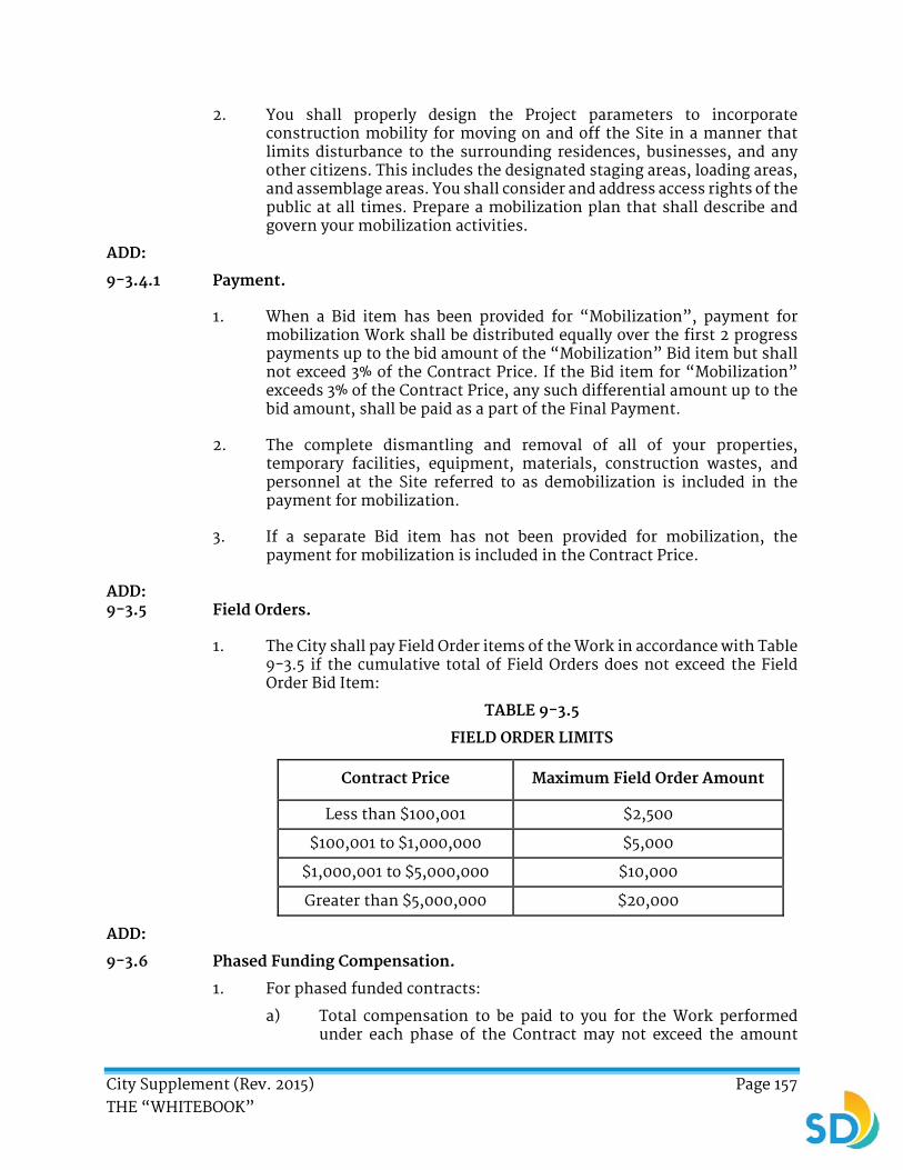
City Supplement (Rev. 2015) Page 157 THE “WHITEBOOK”
2. You shall properly design the Project parameters to incorporate construction mobility for moving on and off the Site in a manner that limits disturbance to the surrounding residences, businesses, and any other citizens. This includes the designated staging areas, loading areas, and assemblage areas. You shall consider and address access rights of the public at all times. Prepare a mobilization plan that shall describe and govern your mobilization activities.
ADD:
9-3.4.1 Payment.
1. When a Bid item has been provided for “Mobilization”, payment for mobilization Work shall be distributed equally over the first 2 progress payments up to the bid amount of the “Mobilization” Bid item but shall not exceed 3% of the Contract Price. If the Bid item for “Mobilization” exceeds 3% of the Contract Price, any such differential amount up to the bid amount, shall be paid as a part of the Final Payment.
2. The complete dismantling and removal of all of your properties, temporary facilities, equipment, materials, construction wastes, and personnel at the Site referred to as demobilization is included in the payment for mobilization.
3. If a separate Bid item has not been provided for mobilization, the payment for mobilization is included in the Contract Price.
ADD: 9-3.5 Field Orders.
1. The City shall pay Field Order items of the Work in accordance with Table 9-3.5 if the cumulative total of Field Orders does not exceed the Field Order Bid Item:
TABLE 9-3.5
FIELD ORDER LIMITS
Contract Price Maximum Field Order Amount
Less than $100,001 $2,500
$100,001 to $1,000,000 $5,000
$1,000,001 to $5,000,000 $10,000
Greater than $5,000,000 $20,000
ADD:
9-3.6 Phased Funding Compensation.
1. For phased funded contracts:
a) Total compensation to be paid to you for the Work performed under each phase of the Contract may not exceed the amount
City Supplement (Rev. 2015) Page 158 THE “WHITEBOOK”
specified for each phase in the final Phased Funding Schedule Agreement unless specified otherwise by a Change Order.
b) Identify the Work to be performed as part of the first phase in the Pre-Award Schedule. The Work elements to be completed as part of each phase shall be functional and complete for the intended purpose in the event the subsequent phases are not authorized by the City.
c) The subsequent phases to the first phase are subject to funding availability by the City. Do not start subsequent phases without prior written authorization from the Engineer.
d) Funds availability for the performance of Work is described in the first Phased Funding Schedule Agreement and subsequently at the final Phased Funding Schedule Agreement. The amount of funds available at award shall be sufficient for the performance of the first phase only. When additional funds are available for the full requirements of the next funding phase, the Engineer shall notify you. The City may modify the amount of funds as available for Contract performance in the final Phase Funding Schedule via Change Order. This procedure also applies to each successive funding phase.
e) The City is not obligated to provide you any amount over that specified in the first Phased Funding Schedule Agreement or final Phased Funding Schedule Agreement as available for Contract performance and authorized by the City Council.
f) You are not obligated to incur costs for the performance of the Work for any funding phase after the first funding phase unless and until written notification is received from the Engineer of an increase in the availability of funds. If so notified, your obligation shall increase only to the extent the Contract performance is required for the additional funding phase for which funds are made available.
g) If the Contract is terminated in accordance with 6-5, “Termination of The Contract for Convenience” the settlement proposal shall be determined pursuant to the procedures established in that section for Work under specific funding phases for which funds have been made available. If the Contract is terminated for default, the City’s rights under the Contract shall apply to the entire multi-phase requirements.
h) A notification to you of an increase or decrease in the funds available for the performance of the Contract under another clause (an “option” or “changes” clause) shall not constitute the notification contemplated in sub-item “a” above.
City Supplement (Rev. 2015) Page 159 THE “WHITEBOOK”
ADD:
9-3.7 Compensation Adjustments for Price Index Fluctuations.
1. Unless otherwise specified, the provisions of this section apply only to the paving asphalt used in the following:
a) Asphalt Concrete Pavement.
b) Asphalt Pavement Repair.
c) Scheduled and Unscheduled Base Repair.
d) Slurry Seal or any other asphalt emulsion.
2. The compensation for paving asphalt shall be increased or decreased for paving asphalt price fluctuations in accordance with 9-1.07 “Payment Adjustments for Price Index Fluctuations” in the Caltrans Standard Specifications.
3. The adjustment in compensation shall also be subject to the following:
a) Show the compensation adjustments provided herein separately on payment estimates. You are liable to the City for decreased compensation adjustments and the Engineer may deduct the amount from moneys payable or that may become payable to you.
b) In the event of an overrun of contract time, adjustment in compensation for asphalt binder included in estimates during the overrun period shall be determined using the California Statewide Crude Oil Price Index in effect on the first business day of the month within the pay period in which the overrun began.
c) In the event that the companies discontinue posting their prices for a field, the Engineer shall determine an index from the remaining posted prices. The City reserves the right to include in the index determination the posted prices of additional fields.
4. You may opt out of the payment adjustments for price index fluctuations when specified in the SSP by submitting a letter with the Bid.
******** END OF PART 1 GENERAL PROVISIONS (A) ********
City Supplement (Rev. 2015) Page 160 THE “WHITEBOOK”
PART 1
GENERAL PROVISIONS (B)
JOB ORDER CONTRACTING (JOC) ONLY To Part 1, General Provisions (A), REVISE with the following:
SECTION 1 - TERMS, DEFINITIONS, ABBREVIATIONS, UNITS OF MEASURE, AND SYMBOLS
1-2 TERMS AND DEFINITIONS. ADD the following:
108. Adjustment Factor (AF) - Your competitive bid price adjustment to the unit prices published in the Unit Price Book for Normal Working Hours (NWH) and Other Than Normal Working Hours (ONWH).
109. Apparent Low Bidder - The Bidder whose Bid, having been publicly opened, initially meets the material requirements of the Bid Documents, and whose JOC (or GRC) Composite Adjustment Factor is the lowest received.
110. Contract Documents - The Contract Documents include the signed Agreement, Addenda, Notice Inviting Bids, funding agency provisions, Bid and documentation accompanying the Bid and any post-bid documentation submitted prior to the Notice of Award when attached as an exhibit to the Contract, Bonds, permits from jurisdictional regulatory agencies, Supplementary Special Provisions (SSP), City’s EOCP Requirements, Standard Specifications “The GREENBOOK”, City Supplement “The WHITEBOOK”, Plans, Standard Drawings, Construction Documents, Mitigation and Monitoring Reporting Program, Reference Specifications listed in the Notice Inviting Bids or the Request for Proposals (RFP), Task Orders, and Change Orders.
111. Composite AF - The adjustment factor that is calculated from the competitively bid NWH AF and the ONWH AF. The Composite AF is used to determine the Apparent Low Bidder. See the Notice Inviting Bids or the Bidding Documents for the formula used to calculate the Composite AF.
112. Maximum Contract Amount - The maximum potential value of the JOC Contract as defined in the Notice Inviting Bids.
113. Minimum Contract Amount - The minimum value of the JOC Contract as defined in the Notice Inviting Bids.
114. Non-Prepriced (NPP) Work Items - The units of Work that are not included in the Unit Price Book (UPB) but are still within the general scope of Work requested by the Engineer under the Contract.

City Supplement (Rev. 2015) Page 161 THE “WHITEBOOK”
115. Pre-priced (PP) Work Items - The units of Work that are included in the Unit Price Book (UPB) requested by the Engineer under the Contract.
116. Request for Proposal (RFP) - The City’s request for proposal for a Task Order.
117. Scope Meeting - A meeting at the Task Order location, attended by the Engineer, you, and any other interested parties to outline and discuss the Scope of Work for the Task. You are required to make all measurements, assessments, and evaluations at the Scope Meeting such that a valid, detailed Proposal will be submitted by the deadline established in the RFP.
118. Task - See Task Order.
119. Task Order - A project assigned to a specific JOC Contract which will be constructed by you in accordance with the terms of the JOC Contract and the Scope of Work.
120. Task Order Proposal - See Proposal. Include a listing of all of the Pre-priced and Non-prepriced Work Items (including competitive quotes) required to complete the Task Order.
121. Unit Price - The price published in the Unit Price Book (UPB) for a specific construction or construction-related Work or line item. Each Unit Price published in the UPB is deemed to be full compensation to accomplish that specific Work or line item.
122. Unit Price Book (UPB) - A comprehensive listing of specific construction-related Work or line items identified by the City together with specified units of measurement and Unit Prices.
City Supplement (Rev. 2015) Page 162 THE “WHITEBOOK”
SECTION 2 - SCOPE AND CONTROL OF WORK
ADD:
2-1 AWARD AND EXECUTION OF THE CONTRACT. DELETE in its entirety and SUBSTITUTE with the following:
1. After the award of the Contract, you shall wait for a Task Order assignment from the City. The City will initiate a Task Order by scheduling and conducting a Scope Meeting with you and other interested parties at the location of the proposed Task Order. The Scope of Work will be transmitted to you prior to the Scope Meeting so that you may review the Scope of Work prior to the meeting and invite Subcontractors and Suppliers to the Scope Meeting. At the Scope Meeting, the Scope of Work for the Task will be presented and discussed with you and you may seek answers to your questions about the Scope of Work. Upon completion of the Scope Meeting, the City will issue an RFP which requires that you prepare and submit a Proposal for the Task Order under consideration on or before a specified due date.
ADD:
2-1.1.7 Task Orders.
1. The City will fund and execute a Task Order when needed. You may be required to Work at any of the City’s facilities. The City makes no commitment as to the award of individual Task Orders. All costs associated with preparing Proposals shall be your responsibility.
2. You may Work only as authorized by Task Orders. Furnish the supplies or services specified in the Task Orders up to and including the Maximum Contract Amount to the City. The City will order at least the Minimum Contract Amount of construction services designated in the Contract Documents.
3. Individual Task Orders determine the Scope of Work. You shall complete the Task Order in accordance with 2-6, “WORK TO BE DONE”.
4. Individual Task Orders are subject to the Contract in its entirety. This is an indefinite-quantity Contract for the supplies or services specified and is effective for the period of 24 months from the date of the Notice to Proceed or the expenditure of the Maximum Contract Value Price as stated in the Notice Inviting Bids, whichever occurs first.
5. Before the issuance of the first Task Order under the Contract, a conference will be conducted by the City to acquaint you with the City’s policies and procedures that are to be observed during the execution of the Work and to develop a mutual understanding relative to the administration of the Contract.
6. Except in an "emergency response" you shall not proceed with any Task Order without having required permits and an NTP signed by the City.

City Supplement (Rev. 2015) Page 163 THE “WHITEBOOK”
7. In the event that “immediate emergency response” is necessary, the City may elect to use an alternative procedure for such type of Task Orders as long as the alternative procedure is not substantially more burdensome to you than the procedure described in this subsection.
8. Your proposals are valid for the duration of the Contract.
9. Before ordering any material or doing any Work, you shall verify all measurements at the Site of a specific Task Order and shall be responsible for the accuracy of the measurements. Extra charge or compensation shall not be allowed based on the difference between actual dimensions and the quantities indicated in the Proposal. You shall verify such items prior to the submission of the Proposal.
10. The City will not entertain claims for additional money when such claims are based upon a contention that the Contract fails to mention a specific item or component of the facility covered by the Task Order and the Work is required in the normal course of operations. For example, surfaced area repair statements may not mention culverts. However, culverts are a typical component of roads, streets, or erosion controls and are shown on the plots or maps provided. As culverts are a typical component of the system, you are responsible for providing all necessary repair or replacement of Work or service.
2-1.1.7.1 Procedure for Ordering Work.
1. As the need for Work arises, the City will send you the Task Order Scope of Work and schedule a Scope Meeting.
2. Upon receipt of the Scope Meeting Invitation, respond within 1 Working Day by confirming attendance at the Scope Meeting in writing.
3. The Scope Meeting will include discussion and establishment of the following:
a) Project number and title.
b) Existing site conditions.
c) Methods and alternatives for accomplishing Work.
d) Definition and refinement of requirements.
e) Detailed Scope of Work.
f) Requirements for design drawings, sketches, Shop Drawings, Working Drawings, submittals, etc.
g) Tentative construction schedule.
h) Preliminary quantity estimates.
4. The City reserves the right to reject your proposal based on unjustifiable quantities, inappropriate line items, inappropriate adjustments, performance periods, inadequate documentation, or other

City Supplement (Rev. 2015) Page 164 THE “WHITEBOOK”
inconsistencies on your part. The City reserves the right to issue the NTP without having a mutual agreement on a final Task Order price.
5. The City reserves the right to not award a Task Order if it is determined to be in the City’s best interests or the proposed cost exceeds the City’s estimate. If we do not award a Task, we will not be liable for Proposal expenses.
6. By submitting a signed Proposal to the City, you are agreeing to accomplish the Work outlined in the Task Order Scope of Work. You shall include the necessary scope items in the Proposal prior to delivering it to the Engineer.
7. Each Task Order Acceptance provided to you in writing will state the timeframe for completion and fixed price of performance. The Task Order Acceptance signed by the Engineer constitutes the City’s acceptance of your Proposal.
2-1.1.7.2 Processing Time Limits.
1. Upon receiving an RFP, submit a Proposal for each Task Order and Task Order Modification to the Engineer on or before the due date stated in the RFP. Proposals are due within 14 Days of the RFP except in the case of accelerated or emergency projects.
2. Analyze each Task Order and submit all Requests for Information (RFI) and Requests for Change (RFC) within 7 Days after issuance of any RFP. Submission of RFI’s or RFC’s will in no way extend the proposal due date unless a proposal extension is granted by the Engineer in writing. Late RFIs and RFCs are subject to Liquidated Damages.
3. Request all proposal extensions in writing (email or letter) and include backup information to support the proposal extension. If a proposal extension is not granted by the engineer in writing prior to the proposal due date, the proposal will be considered late if a complete proposal is not submitted on or before the proposal due date. Late proposals are subject to Liquidated Damages.
4. Once you have submitted your proposal, be available for a Proposal Negotiation Meeting within 24 hours of being notified by the Engineer via fax, e-mail, or telephone.
5. In the Proposal Negotiation Meeting, the City will discuss with you the line items and quantities in your proposal in order to determine the validity and reasonableness of your proposal.
6. After the Proposal Negotiation meeting, the City will provide a proposal acceptance and either a counter-proposal or a marked-up proposal based on the proposal negotiation. Within 2 Days of receiving the proposal acceptance and counter-proposal or marked-up proposal, sign and return to the Engineer by email the scanned proposal acceptance OR email a list of the disagreed line items and quantities and the specific

City Supplement (Rev. 2015) Page 165 THE “WHITEBOOK”
reasons for not agreeing with the line item and quantity. For any disagreed line items, include your proposed line item and quantity revisions.
7. The City will review any disagreed line items and either accept, reject, or partially accept your proposed revisions to the counter-proposal or marked-up proposal. If the City accepts any revisions, the City will provide you a revised proposal acceptance and counter-proposal or revised marked-up proposal. You are required to review the revised counter-proposal or marked-up proposal and shall sign and return the revised proposal acceptance within 1 Working Day.
8. Submit RFIs, RFCs, and Proposals on time. If you fail to submit a Proposal in accordance with these specifications, liquidated damages will be collected in accordance with 6-9, “Liquidated Damages”.
2-1.1.7.3 Payment.
1. The payment for a Task Order and the Task Order price indicated on your Proposal Acceptance is determined by summing the value of all of the PP Items (from the UPB) and the NPP Items (from 2 competitive quotes) required for completing the Task Order.
a) The price of a PP Item is determined by the following formula:
PP Item Price = Unit Price (from UPB) x quantity x AF (NWH or ONWH)
b) The price of a NPP Item is determined by the following formula:
NPP Item Price = Lowest of two competitive quotes x AF (NWH or ONWH)
c) See the Notice Inviting Bids for the applicable Unit Prices and UPB.
d) Include a list of all the PP Items and NPP Items along with the required quantities and costs as indicated in the formulas above in your Proposal for each Task Order. The Proposal format shall be as indicated in the Notice Inviting Bids.
ADD:
2-5 PLANS AND SPECIFICATIONS. ADD the following:
1. There may be no Plans for the purposes of bidding or construction. Specific Work instructions for each Task Order will be issued to you on the Task Order Scope of Work.
2-5.2 Precedence of Contract Documents. ADD the following:
6. The Work instructions on the Task Order Scope of Work shall have the same rank as “Supplemental Special Provisions” and “Plans” when used in conjunction with 2-5.2, “Precedence of Contract Documents”.
7. Task Order Modifications and revised Scope of Work shall have the same rank as “Change Orders and Supplemental Agreements” when used in conjunction with 2-5.2, “Precedence of Contract Documents”.
City Supplement (Rev. 2015) Page 166 THE “WHITEBOOK”
SECTION 3 - CHANGES IN WORK
3-1.1 General. ADD the following:
3. You may request a modification in the Task Order price or an extension of time for completion of the Task Order due to changes in the Work that are not within the s cope of the Task Order.
4. You shall not be entitled to compensation for any Extra Work performed unless the Engineer has issued a written Task Order Modification designating the following:
a) The Extra Work to be performed.
b) The price of the Extra Work.
c) The time for completion of the Extra Work.
5. If the Engineer agrees that Work is added or deleted, the Task Order price shall be adjusted using the Procedure for Ordering Work in accordance with 2-1.1.7.1, “Procedure for Ordering Work”, 2-1.1.7.2, “Processing Time Limits”, and 2-1.1.7.3, “Payment”.
ADD:
3-2.1 General. To Paragraph (1), Sentence (1), DELETE in its entirety and SUBSTITUTE with the following:
If the Engineer deletes any item of the Work in part or in its entirety, the reduction in Contract Price shall reflect a credit for the full value of the deleted portion of the Work, including anticipated profit and overhead. If the Engineer orders Work to be added or deleted, the Task Order price shall be modified in accordance with 2-1.1.7.1, “Procedure for Ordering Work”, 2-1.1.7.2, “Processing Time Limits”, and 2-1.1.7.3 “Payment”.
ADD:
3-2.2 Contract Unit Prices. ADD the following:
1. The Unit Price Book shall be consistent for the entire term of the JOC Contract including the Task Order Modification Work executed during and after the Contract expiration. The Adjustment Factors shall not change for a period of 2 years (730 Days) from the Contract Award Date and for any Task Order Modifications executed after the expiration of the Contract that are required to complete a Task Order. See the Notice Inviting Bids for the identification of the Unit Price Book.

City Supplement (Rev. 2015) Page 167 THE “WHITEBOOK”
SECTION 6 - PROSECUTION, PROGRESS, AND ACCEPTANCE OF THE WORK
6-1.2 Commencement of the Work. ADD the following:
5. The Work shall be completed within the time specified in the Task Order Acceptance.
6-7 TIME OF COMPLETION. To Item 1, DELETE in its entirety and SUBSTITUTE with the following:
1. Refer to the Task Order Scope of Work documents.

City Supplement (Rev. 2015) Page 168 THE “WHITEBOOK”
SECTION 7 – RESPONSIBILITIES OF THE CONTRACTOR
7-8.6 Water Pollution Control. ADD the following:
6. Based on preliminary assessments by the City, the Task Orders may be subject to Water Pollution Control requirements. Refer to the Task Order Scope of Work.
******** END OF PART 1 GENERAL PROVISIONS (B) ********

City Supplement (Rev. 2015) Page 169 THE “WHITEBOOK”
PART 1
GENERAL PROVISIONS (C)
DESIGN-BUILD (DB) AND MULTIPLE AWARD CONSTRUCTION CONTRACT (MACC) CONTRACTING ONLY
To Part 1, General Provisions (A), REVISE with the following:
SECTION 1 - TERMS, DEFINITIONS, ABBREVIATIONS, UNITS OF MEASURE, AND SYMBOLS
1-2 TERMS AND DEFINITIONS. ADD the following:
108. Apparent Winner - The Design-Builder whose Proposal is selected to be the most advantageous (best value) to the City.
109. Architect-Engineer - You or your designated Architect-Engineering firm.
110. Bridging Documents - The City’s preliminary and conceptual plans and specifications that shall be used by you as a minimum basis to design and construct the Project. See the RFP, Attachment A.
111. Construction Phase - The period set forth in the Schedule beginning with the issuance of the Construction Notice to Proceed and ending on the date of Acceptance.
112. Designer - See Architect-Engineer.
113. Design-Builder - See Contractor.
114. Design Work - That portion of the Work consisting of the professional design services required to be provided in connection with the design of the Project or portions of the Project as set forth in the Contract Documents.
115. Design Materials - Documents, Shop Drawings, Working Drawings, electronic information, data, plans, drawings, sketches, illustrations, specifications, descriptions, models, and other information developed that are prepared, furnished, delivered or required to be delivered by you to the Engineer under the Contract Documents and/or or developed or prepared by you specifically to discharge your responsibilities.
116. Design Phase - The period set forth in the Schedule commencing with your receipt of a Limited NTP and ending upon the date the Engineer approves the Construction Documents.
117. Multiple Award Construction Contract (MACC) - Also known as Multiple Award Design-Build Contracts. Provisions for Design-Build contracts shall apply to MACC contracting.

City Supplement (Rev. 2015) Page 170 THE “WHITEBOOK”
118. Order of Magnitude Documents - The drawings, specifications and other documents by you for the City’s review and approval prior to the preparation of the Construction Documents.
119. Request for Proposal (RFP):
a) The City’s solicitation to prospective proposers upon which an evaluated selection of a Design-Builder shall be made.
b) The standardized form used by the City to request a Proposal from you for proposed changes in the Work.
120. Request for Qualifications (RFQ) - The City’s solicitation to prospective Design-Builders for SOQ.
121. Statement of Qualifications (SOQ) - The document you submit for the City’s consideration in response to the RFQ stating your expertise, experience, and capabilities and for providing other required information to design and build the Project.
122. Task - See Task Order.
123. Task Order - A project assigned to a specific As-Needed Contract which shall be constructed by you in accordance with the terms of the As-Needed Contract to which it is assigned.
124. Task Order Authorization - For As-needed Contracts, the documents the City transmit to you which indicate the Work instructions, Scope of Work, and time duration allotted for a particular Task or Project.
125. Task Order Proposal - For As-needed Contracts, your irrevocable offer to perform Work associated with a Task Order that refers to your quote for a firm fixed-price and schedule for the completion of the specified Scope of Work. Your Proposal shall be on electronic forms provided by the City and shall be in an electronic version compatible with the City’s systems. The Proposal Submittal may also require a Work schedule, EOC forms, or other documentation that the City may require for a specific Task Order.

City Supplement (Rev. 2015) Page 171 THE “WHITEBOOK”
SECTION 2 - SCOPE AND CONTROL OF WORK
ADD:
2-1 AWARD AND EXECUTION OF THE CONTRACT. DELETE in its entirety and SUBSTITUTE with the following:
1. The award and execution of the Contract shall be as provided for in the Special Provisions, Instruction to Bidders, Notice Inviting Bids, or the Request for Proposals (RFP).
ADD:
2-1.1.7 Document Ownership.
1. Once you have received any compensation for the Work performed, all electronic or hard copy documents, including but not limited to original plans, studies, sketches, drawings, computer printouts and files, and specifications prepared in connection with or related to the Work shall become the City’s property.
2. The City’s ownership of these documents includes use, reproduction, or reuse of all incidental rights whether or not the item of the Work for which they were prepared has been performed.
3. The City’s ownership entitlement arises upon payment or any partial payment for the Work performed and includes ownership of Work products completed under the Contract.
4. This subsection shall apply whether your services are terminated by the completion of the Project or in accordance with other provisions of the Contract. You may make copies of all such plans, studies, sketches, drawings, computer printouts and files, and specifications.
2-3.4 Subcontract Requirements. ADD the following:
6. You shall not hire or allow any entity such as the City’s consultant and any sub-consultant who participated in creating the Bridging Documents or Contract Documents for this project to participate in design services, construction management, and any other construction services related in any way to this project without the City’s written consent.
7. You shall pay the Subcontractors for your approved invoice amounts out of amounts paid by the City to you no later than 14 Days from your receipt of payment from the City. Nothing in this paragraph is construed to impair your right and any Subcontractor’s right to negotiate fair and reasonable pricing and payment provisions among yourselves.
8. In the case of a deficiency in the performance of the Subcontractor’s services, you shall notify the Engineer in writing of any withholding of payment to the Subcontractor, specifying the following:
a) The amount withheld.
b) The specific cause under the terms of the subcontract for withholding payment.
City Supplement (Rev. 2015) Page 172 THE “WHITEBOOK”
c) The connection between the cause for withholding payment and the amount withheld.
d) The remedial action the Subcontractor shall take in order to receive the amount withheld.
9. Once the Subcontractor corrects the deficiency, you shall pay the Subcontractor the amount withheld within 14 Days of your receipt of the City’s next payment.
2-5.2 Precedence of Contract Documents. DELETE in entirety and SUBSTITUTE with the following:
1. If there is a conflict between any of the Contract Documents, the document highest in the order of precedence shall control. The order of precedence, from highest to lowest, shall be as follows:
a) Permits (issued by jurisdictional regulatory agencies including environmental documents).
b) Change Orders and Supplemental Agreements; whichever occurs last.
c) The signed written Agreement.
d) Addenda.
e) Bid / Price Proposal.
f) Request for Proposal (RFP).
g) Supplemental Special Provisions.
h) Project Plans.
i) Standard Drawings.
j) “WHITEBOOK” (City Supplement).
k) “GREENBOOK” (Standard Specifications for Public Works Construction).
l) Reference Specifications.
2. When additional EOCP requirements by the funding sources are included or incorporated by reference in the Contract Documents, the funding source’s requirements shall govern unless specified otherwise in the SSP.
3. With reference to the drawings the order of precedence shall be as follows:
a) Figures govern over scaled dimensions.
b) Detail drawings govern over general drawings.

City Supplement (Rev. 2015) Page 173 THE “WHITEBOOK”
c) Addenda and Change Order drawings govern over Plans.
d) Plans govern over Standard Drawings.
4. When a conflict exists between the ADA, Title 24, and the City Supplement, the most restrictive requirement shall be followed.
5. When there is a conflict among subsection 700-3.5, “Standards”, Section 86 of the 2015 Standard Specifications, and the 2015 Standard Plans of the Caltrans, the Caltrans standards shall control.
6. The Work instructions on the Task Order Scope of Work shall have the same rank as “Special Provisions” and “Project Plans” when used in conjunction with 2-5.2, “Precedence of Contract Documents”.
7. Task Order modifications and revised Scope of Work shall have the same rank as “Change Orders and Supplemental Agreements” when used in conjunction with 2-5.2, “Precedence of Contract Documents”.
ADD:
2-5.6 As-Builts.
1. You are responsible for the completion of As-Built drawings.
2. The As-Built drawings shall include the information required for various asset types listed in 2-5.4.2, “Asset Specific Red-lines”.
3. Prior to Acceptance, prepare and submit 1 complete set of full sized, 24 inch by 36 inch, original Mylar final As-Built Drawings (CADD plots) prepared in accordance with the City’s CADD standards. Each CADD Mylar drawing sheet shall be wet stamped and signed by qualified responsible engineers registered in the State of California and shall be stamped and wet signed by the architect or engineer of record as required by law. Other applicable portions of the drawing title blocks shall also be signed by you.
4. Drawing Mylars shall be 3 mils minimum thickness.
2-5.6.1 Payment.
1. The payment for As-Built drawings shall be included in the Contract Price.
ADD:
2-5.7 Order of Magnitude Documents and Construction Documents.
1. After the Limited NTP, prepare the Order of Magnitude Documents for review and approval by the City and then prepare the Construction Documents. Develop and detail the Order of Magnitude Documents and Construction Documents consistent with the intent of the Contract Documents. Include documents customarily required for regulatory approval by governmental agencies.
2. The Order of Magnitude Documents shall show the scale and relationship of Project components, outline the nature and structural exterior and 3
City Supplement (Rev. 2015) Page 174 THE “WHITEBOOK”
dimensional scale of the Project, and shall set and describe in detail the configuration and character of the Project for the complete and final preparation of the Construction Documents.
3. The Construction Documents shall provide information customarily necessary for the use of such documents by those in the building trades and shall include all documents required for the complete and final construction of the Project other than such details customarily developed in the Working Drawings and Shop Drawings or otherwise during construction.
4. You are responsible for obtaining all reviews and approvals for building permit(s) independently of the Order of Magnitude Documents review.
2-5.7.1 Use of Computer Aided Drafting and Design.
1. Use CADD for the preparation of Plans and As-Built drawings in accordance with the City’s CADD Standards. Conversions of CADD Work from any CADD format to City standard MicroStation format shall not be acceptable unless specified otherwise in the Contract Documents.
2-5.7.2 Reliance on Approvals.
1. You may rely on the Engineer’s approval for the general scope and purpose included in the Bridging Documents. The Engineer’s approval is not a specific approval with respect to the Design Materials. The Engineer has the right to accept, reject, or suggest changes to the Order of Magnitude Documents to achieve conformity with the general scope included in the Bridging Documents with no increase in Contract Price or Contract Time.
a) If the Engineer revokes, modifies, or otherwise changes a material in any way after such portion of the Work has been designed and approved or modifies the original Bridging Documents in a material manner requiring modification to one or more systems which have been designed and approved, you may request a Change Order in accordance with 3, “CHANGES IN WORK” provided that, prior to such approval, you have made the City aware of future design decisions which may be affected by such approval.
2. The Engineer shall not issue a Change Order for Extra Work when the Extra Work is due to your fault or neglect or unauthorized deviations from the Bridging Documents.
2-5.7.3 Review of Construction Documents and Field Conditions.
1. You are responsible for errors, inconsistencies, or omissions in the Construction Documents. You shall take field measurements, verify field conditions, and compare such field conditions and other information known to you with the Contract Documents before commencing activities.

City Supplement (Rev. 2015) Page 175 THE “WHITEBOOK”
2-5.7.4 Shop Drawings and Working Drawings, Product Data, and Samples.
1. Maintain at the Site 1 record copy of the Contract Documents, Drawings, Specifications, Addenda, Construction Documents, and any Change Orders in good order and marked to record changes and selections.
2. Maintain approved Shop Drawings and Working Drawings, product data, samples and similar required submittals at the Site.
3. Review and take appropriate actions for Shop Drawings and Working Drawings, product data, samples, and similar submittals. Upon request by the Engineer, provide documents for the review of Shop Drawings and Working Drawings, product data, samples, and similar submittals.
4. Provide a register of all Submittals that are scheduled for review by the City, designers, or both.
5. You are not relieved of the responsibility for the deviations from requirements of the Contract Documents by the Engineer's approval of Shop Drawings and Working Drawings, product data, samples, or similar submittals unless you have specifically informed the Engineer of such deviations at the time of the submittal and the Engineer has given written approval to the specific deviation.
6. You are not relieved of responsibility for errors or omissions in the Shop Drawings and Working Drawings, product data, samples, or similar submittals by the Engineer's approval.
2-6 WORK TO BE DONE. ADD the following:
3. The minimum design requirements for the Project are set forth in the Bridging Documents, the information provided for sample or model facility, or both. Do not proceed with nor pay for any Design Work until the City issue a Limited NTP.
4. Comply with the Final Environmental Document, including incorporating environmental considerations into the Project design, modifying the Project design, where applicable, and mitigating impacts.
5. Keep the Engineer informed of the progress and quality of the design and construction of the Project.
6. Organization of the Design Materials into divisions, sections and articles and arrangement of drawings is for convenience and does not control dividing the Work among Subcontractors or in establishing the extent of the Work performed by any trade.
7. Unless otherwise specified in the Contract Documents, provide and pay for labor, materials, equipment, tools, construction equipment and machinery, water, heat, utilities, transportation, and other facilities and services necessary for the proper execution and completion of the Work, whether temporary or permanent and incorporated in the Work.
8. Respond to, and ensure Subcontractors respond to, RFI, substitution requests, and Change Order requests. Provide the Engineer with copies of all correspondence within 24 hours of receipt, and conduct weekly review meetings with the Engineer to discuss these items.

City Supplement (Rev. 2015) Page 176 THE “WHITEBOOK”
ADD:
2-6.1 Construction Obligations.
1. Do not perform any construction Work in connection with the Project prior to receipt of NTP. The City shall make no payment for any construction Work performed prior to issuance of the NTP and applications for payment for such Work are not binding on the City.
2. If you desire to begin constructing a portion of the Project prior to achieving final design of the Project, you shall in writing notify the Engineer at least 3 Working Days in advance of proposed construction activities to seek the Engineer’s approval and include proof of receipt of all applicable permits. The Engineer shall provide you with a standard form for this purpose. Do not move forward with any construction activities without providing such notice and receiving the Engineer’s approval.
3. If you desire to modify the design documents after they have been approved by the Engineer, obtain the Engineer’s prior written approval before making any such modifications and any construction changes based upon such modifications.
ADD:
2-6.2 Standards of Performance.
1. Use the degree of care and skill ordinarily exercised by reputable professionals practicing in the same field of service in the State of California.
2. The Construction Documents shall be prepared, signed, and stamped by and under the direct responsible charge of an architect or engineer duly licensed in the State of California.
3. Perform the Work in accordance with the professional standards applicable to projects, buildings, or Work of complexity, quality and scope comparable to the Project.
4. You are the Engineer of Record (Engineer of Work).
ADD:
2-6.3 Use of Design Materials.
1. The Engineer has unlimited rights to copy and use in connection with the Project all Design Materials, including the right to use them on the Project at no additional cost to the City regardless of degree of completion provided that said services performed have been fully paid for, exclusive of the amounts disputed by the City in good faith, as required by the terms of the Contract.
2. You agree to and grant to the City and any assignee or successor of the City as owner of the Project a royalty-free license to any such Design Materials as to which you may assert any rights under the patent or

City Supplement (Rev. 2015) Page 177 THE “WHITEBOOK”
copyright laws. You agree to assign outright and exclusively to the City all copyrights in the design appearance of the Project. You, as part of your agreements with Subcontractors, shall secure such license and use rights from each such entity, and shall defend, indemnify and hold the City and any successors or assigns harmless from any claims by such entities for copyright or patent infringement.
ADD:
2-6.4 Local Conditions.
1. You represent that you have taken steps necessary to ascertain the nature and location of the Work and that you have investigated and satisfied yourself as to the general and local conditions which are applicable to the Work such as the following:
a) Conditions bearing on transportation, disposal, handling, and storage of materials.
b) The availability of labor, water, power, and roads;
c) Normal weather conditions.
d) Observable physical conditions at the Site.
e) The surface conditions of the ground.
f) The character of equipment and facilities needed prior to and during the performance of the Work.
2. To the extent you encounter subsurface or concealed conditions which differ materially from those represented in the Contract Documents, you shall notify the Engineer promptly before conditions are disturbed and in no event later than 4 Working Days after the first observance of the conditions if a Change Order is contemplated by you due to such condition.
3. If the subsurface or concealed conditions are determined to be of Hazardous Materials or Waste, you shall immediately notify the City no later than 1 Working Day and shall proceed as set forth in these specifications and the exhibits of the Contract.
4. You shall not be entitled to any adjustment in Contract Price or Contract Time or shall have been deemed to have waived your right to such a Claim if:
a) You knew of the existence of such conditions at the time you made a final commitment to the City in respect to the Contract Price and Contract Time by becoming bound under the Contract.
b) The existence of such condition could reasonably have been discovered or revealed as a result of any examination or investigation of the Site and contiguous areas suggested or required by the Contract Documents.

City Supplement (Rev. 2015) Page 178 THE “WHITEBOOK”
c) You failed to give the written notice within the time and as required by this subsection.
ADD:
2-6.5 Model or Example Facility Information.
1. If any element required by the Contract Documents is not clearly defined, rely on the model or example facility information provided in the Contract Documents for the standard requirements. Contact the City’s project manager for a site visit of facility prior to finalization of Bid.
ADD:
2-6.6 Procedures for Review of Design Materials.
1. The review process for submitted materials shall be as follows:
a) The Engineer shall respond to your Submittals or re-Submittals within 15 Working Days of their receipt unless the Engineer gives you prior notice. Within 5 Working Days of receipt of the Engineer’s comments, you shall resolve and discuss with the Engineer any outstanding issues as a result of the Engineer’s comments.
b) Unless agreed with the Engineer in advance, submit any required revised or final Submittals within 10 Working Days of the resolution of the submittal issues.
c) Ensure that the comments of the Engineer are addressed by the designers. 1 copy of all Submittals reviewed by the designer shall be provided to the Engineer.
ADD:
2-18 PERSONNEL CHANGES FOR DESIGN-BUILD CONTRACTS.
1. Ensure that key personnel, as identified in your Proposal shall not be replaced or substituted without the Engineer’s prior approval. You shall be liable for damages incurred by the City as a result of unauthorized substitution of each key personnel.
2. The City reserves the right to have any of your employees or Subcontractor’s employees removed from the Project upon written notice from the City to you without cause.
3. Nothing contained in the Contract Documents shall create a contractual relationship between the City and any third party, or Subcontractors. However, it shall be understood and agreed that the City, as the third party beneficiary, is an intended third-party beneficiary of all Contracts for design or engineering services and all Subcontracts, purchase orders, and other agreements between you and third parties.
City Supplement (Rev. 2015) Page 179 THE “WHITEBOOK”
SECTION 3 - CHANGES IN WORK
ADD:
3-2.6 Proposal.
1. Your post award proposal in response to the City’s RFP shall be on forms acceptable to the Engineer. Your proposal shall certify in writing that the amounts included cover all direct, supplemental, indirect, consequential, and cumulative costs and delays as applicable and that those costs and delays would be or were necessarily incurred, despite your reasonable and diligent efforts to mitigate them. Mitigation efforts undertaken by you shall be described.
2. Where the change in Contract Price is to be determined on the basis of the “cost of the Work involved”, your itemized estimates shall detail all applicable elements of cost, including, but not limited to, labor hours and payroll costs, quantities, crew mixes, production rates, material costs, Subcontractor and Supplier costs, equipment costs, and supplemental costs. Where the change in Contract Price arises from changes in the schedule of all or part of the Work or where a change in Contract Time is sought, the submittal shall include analysis required by 6-1.5, “Contract Time Extensions”.
ADD:
3-3.2.1 General. ADD the following:
1. If shown on the Bid Proposal, the contingency funds including City Contingency and Allowances may be used by you with the Engineer’s prior approval. The contingency funds shall be available to provide additional funds for Extra Work. The contingency funds shall not be available for the following:
a) Work required due to you and your officers’, agents’, or employees' failure to perform Work or Services according to the terms of the Contract.
b) Uninsured losses resulting from your and your officers’, agents’, or employees’ negligence. The City reserves the right to seek reimbursement for any costs expended due to the errors or omissions of your officers, agents, or employees providing Services to the Project.
2. 100% of the unused portions of the City Contingency and Allowances shall revert to the City upon Acceptance.
ADD:
3-6 ADDITIONAL COSTS.
1. Additional costs are those costs that can be reasonably determined to be related to your errors or omissions, and may include your, ours, or your Subcontractors’ overhead, construction, materials, demolition, and related costs. You shall not be paid for Work or Services required due to
City Supplement (Rev. 2015) Page 180 THE “WHITEBOOK”
your errors or omissions and you shall be responsible for any additional costs associated with such errors or omissions.
2. You shall reimburse the City for its additional costs due to your errors or omissions.
ADD:
3-7 ADDITIONAL SERVICES.
1. The City has the right to direct you to perform additional services beyond those Services detailed in the Scope of Work and Services (Additional Services).
2. You shall promptly perform any Additional Services as directed by the Engineer in accordance with the Contract Documents. You shall request a Change Order when seeking reimbursement for Additional Services requested by the City.
3. If at any time you contend that the City is asking you to perform Additional Services which are not specifically identified as such by the City, you shall immediately give the Engineer written notice within 24 hours prior to performing the Services in question. The notice shall state that you intend to seek additional compensation beyond the amount specified in the Bid. Furnishing timely, accurate, and advance written notices shall be a condition precedent to your ability to seek additional compensation from the City.
4. You shall not perform and shall not be entitled to compensation for any Additional Services unless the Engineer has, in advance, authorized in writing performance of the Additional Service. Under no circumstances shall you be paid for Additional Costs.
5. Your Compensation Rate Schedule for design professionals is attached to the Contract. Payment for any Additional Services shall be in accordance with the Compensation Rate Schedule and no increases to the Compensation Rate Schedule may be made during the Contract Time.
6. You shall separately submit to the Engineer a certificate and application for monthly payment of any authorized Additional Services. No markup shall be allowed for Additional Services.

City Supplement (Rev. 2015) Page 181 THE “WHITEBOOK”
SECTION 4 – CONTROL OF MATERIALS
4-1.6 Trade Names or Equals. ADD the following:
11. Provide 1 copy of all designer reviewed submittals to the Engineer.

City Supplement (Rev. 2015) Page 182 THE “WHITEBOOK”
SECTION 5 - UTILITIES
ADD:
5-1 LOCATION. ADD the following:
1. Coordinate the review of the Project design drawings by the utility agencies at every design phase submittal.
2. Determine locations and elevations of all active and abandoned underground utilities in the Project area that may affect Project construction activities.
3. Provide all required information for the construction or relocation of all public or private utilities that shall be constructed or relocated as a result of this Project.
4. Provide designs for wet utility crossings.
5. Coordinate utility facility and equipment shutdown requirements with the Engineer.
ADD:
5-4 RELOCATION. To the Paragraph (2), DELETE in its entirety and SUBSTITUTE with the following:
Alter, relocate, and reconstruct all utilities, including water and sewer connections, as necessary to construct the Project. Utilities not indicated on your Plans that are found to interfere with the Work shall be relocated, altered, or reconstructed by the utility owner or by you at no additional cost to the City. You shall contact and coordinate alteration, relocation, or reconstruction of gas, electric, cable, and telephone service connections with the owner of those utilities.
ADD:
5-5 DELAYS. ADD the following:
1. You shall not be entitled to an extension of the Contract Time or for compensation for Extra Work or delays attributable to utility or substructure relocations or alterations when the existing utilities or substructures were identified in the Contract Documents, utility records, As-Built and record drawings, or other relevant records and archives pertaining to utility locations that you could reasonably have been expected to be aware of and when they were marked out by USA.

City Supplement (Rev. 2015) Page 183 THE “WHITEBOOK”
SECTION 6 - PROSECUTION, PROGRESS, AND ACCEPTANCE OF THE WORK
6-1.2 Commencement of the Work. ADD the following:
5. Do not begin construction of the Project or any portions thereof until the Engineer approves the design for the Project or portion thereof, and issues a Notice to Proceed for Construction, to provide the City the defenses set forth in California Government Code §830.6.
6-7 TIME OF COMPLETION. To item 1, DELETE in its entirety and SUBSTITUTE with the following:
1. You shall complete the Work within the time specified in the Notice Inviting Bids or RFP for Design-Build or MACC Contracts.
ADD:
6-8.4 Latent and Patent Defect Warranty.
1. You shall warrant to the City that the construction, including all materials and equipment furnished as part of the construction, shall be free of latent and patent defects in materials and workmanship. The Engineer shall first provide you an opportunity to correct or replace any latent and patent defect at your own expense, if notified by the City within 4 years after the date of Acceptance for patent deficiency and 10 years for a latent deficiency. If you fail to repair and replace the reported deficiency, the City shall repair the deficiency and charge you for the repair.
City Supplement (Rev. 2015) Page 184 THE “WHITEBOOK”
SECTION 7 – RESPONSIBILITIES OF THE CONTRACTOR
7-8.6 Water Pollution Control. ADD the following:
6. You shall comply with the City of San Diego Storm Water Standards and Hydromodification Plan (HMP). The municipal permit requires development and implementation of a Standard Urban Storm Water Mitigation Plan (SUSMP) to reduce the negative impacts from development runoff to receiving waters.
7. You shall apply the San Diego Regional Water Quality Control Board standards to the project and shall provide all design and technical documentation needed to comply with these standards.
8. Your As-Builts shall accurately record the final location and configuration of permanent BMPs.
9. You shall obtain the regulatory approvals and permits required for the Project unless specified otherwise.
10. All costs, fines, penalties, additional mitigation, or litigation costs associated with your negligence to comply with any of the permit conditions, federal, state, and local laws, ordinances, codes, orders and regulations, shall be your responsibility.
ADD:
7-15.1 Indemnification and Defense.
7-15.1.1 Non-Design Services.
1. Other than in the performance of Services which shall be solely as addressed in these specifications to the fullest extent permitted by law, you shall defend with legal counsel reasonably acceptable to the City, indemnify and hold harmless the City and its officers, agents, departments, officials, and employees (Indemnified Parties) from and against all claims, losses, costs, damages, injuries (including injury to or death of an employee of yours or your Subcontractor), expense and liability of every kind, nature, and description (including incidental and consequential damages, court costs, litigation expenses and fees of expert consultants or expert witnesses incurred in connection therewith and costs of investigation) that arise out of, pertain to, or relate to, directly or indirectly, in whole or in part, any services (including construction services) performed under the Contract by you, any Subcontractor, anyone directly or indirectly employed by them, or anyone that they control.

City Supplement (Rev. 2015) Page 185 THE “WHITEBOOK”
2. Your duty to defend, indemnify, protect, and hold harmless shall not include any claims or liabilities arising from the active negligence, sole negligence, or willful misconduct of the Indemnified Parties.
7-15.1.2 Design Services.
7-15.1.2.1 Indemnification.
1. To the fullest extent permitted by law (including, without limitation, California Civil Code §2782.8), with respect to the performance of Services, you shall indemnify and hold harmless the City, the City’s officers, or employees, from all claims, demands or liability that arise out of, pertain to or relate to your negligence, recklessness, or willful misconduct or those of your officers or employees and others hired or controlled by you.
7-15.1.2.2 Defense.
1. You shall Work in good faith to procure applicable insurance coverage for the cost of any defense arising from all claims, demands or liability that arise out of, pertain to or relate to your negligence, recklessness, or willful misconduct and those of your officers or employees.
7-15.1.3 Enforcement Costs.
1. You agree to pay all costs the City incurs enforcing the indemnity and defense provisions set forth in these specifications.
7-15.1.4 Insurance.
1. The provisions of 7-15, “INDEMNIFICATION AND HOLD HARMLESS AGREEMENT” shall not be limited by the requirements of 7-3, “INSURANCE” related to insurance.
7-15.1.5 Survival of Obligation.
1. All representations, indemnifications, warranties, and guarantees made in, required by, or given in accordance with the Contract Documents as well as all continuing obligations indicated in it, shall survive completion and acceptance of the Work and termination or completion of the Contract.
ADD:
7-23 DESIGN-BUILDER’S RESPONSIBILITIES.
1. Keep the Engineer informed of the progress and quality of the design and construction of the Project
2. You shall assume responsibility for all negligent errors, omissions, or acts arising from the design and architectural Services you provide under the Contract, including any negligent errors, omissions, or acts of your agents, officers, and employees.
City Supplement (Rev. 2015) Page 186 THE “WHITEBOOK”
3. You are responsible for coordinating all construction means, methods, techniques, sequences, and procedures including the following:
a) Coordinate scheduling of Submittals and all design and construction of the Project to ensure the efficient and orderly sequence of the construction. Monitor and report periodically to the Engineer actual performance compared to Project Schedule. Prepare and submit to the Engineer, during both the Design Phase and the Construction Phase, monthly progress reports, in a manner and format acceptable to the Engineer, on the Work accomplished during the prior monthly period.
b) Monthly reports shall be furnished at the time of submission of each monthly Application for Payment. As part of such report, provide an updated Schedule, including CPM illustrating the progress which has been made and specifically whether the Work is on schedule or behind schedule and actions being taken to correct Schedule slippage. The monthly report shall also set forth your projected progress for the forthcoming month.
c) Coordinate design and construction requirements with governmental agencies, utilities, and all other parties either involved in infrastructure improvements or otherwise affected by the design and construction requirements.
d) Provide the City with 2 copies of all Submittals approved by you.
e) Assist the City’s staff and reasonably cooperate with the City’s legal, financial, design and construction consultants and all other designated representatives during the design and construction of the Project.
f) Implement suitable management systems and Work plans for the Project relative to safety, quality assurance and managing and controlling the Work.
g) Be solely responsible for selecting the means, methods, techniques, sequences, or procedures of performing the Work. If you elect or choose to adopt or follow, in whole or part, any means, means, methods, techniques, sequences or procedures of performing the Work developed or suggested by the City, you do so at your own risk and bear sole responsibility for such election or choice. The City shall assume no responsibility thereof and in no way shall be held liable for any defects in the Work, or increased costs or delays in the Work, which may result from or be caused by your use of such means, methods, techniques, sequences, or procedures.
City Supplement (Rev. 2015) Page 187 THE “WHITEBOOK”
SECTION 9 - MEASUREMENT AND PAYMENT
9-2.1 Schedule of Values (SOV). ADD the following:
12. Provide a cross reference listing in two parts. The first part lists each scheduled activity with the breakdown of the respective valued items making up the total cost of the activity. The second part lists the valued item with the respective scheduled activity or activities that make up the total cost indicated. In the case where a number of schedule activities make up the total cost for a valued item (shown in the SOV) indicate the total cost for each scheduled activity. The total amount of each part shall equate to the Contract Price.
ADD:
9-4 PRICE CONDITIONS.
1. If specified in the RFP, the Contract Price shall not exceed the City’s stipulated estimate of the Project’s total cost.
ADD:
9-5 SERVICES FEE.
1. Except as otherwise expressly provided in the Contract, as full and complete compensation for performance of all Services and obligations under the Contract, you shall be compensated only for the following:
a) Architectural, engineering, and other professional Subcontractors such as structural, civil, mechanical, electrical engineers, communications, graphics and art Subcontractors, landscape architects, and acoustical, audio visual, lighting, traffic and security Subcontractors.
b) Estimating and construction management.
c) Construction supervision and project management personnel such as superintendents, project managers, project secretaries, project engineers, project accountants, and all your other personnel wherever located.
d) On-Site and offsite equipment, supplies and facilities such as computers, estimating, dictating, communication and accounting equipment, office space, trailers and storage facilities.
e) Home-office and field overhead costs of any type including document control and retention.
f) Your profit.
City Supplement (Rev. 2015) Page 188 THE “WHITEBOOK”
ADD:
SECTION 10 – GREEN BUILDINGS AND STORM WATER MANAGEMENT
10-1 LEADERSHIP IN ENERGY AND ENVIRONMENTAL DESIGN (LEED) REQUIREMENTS.
1. The Project design and construction shall comply with City Council Green Building Policy 900-14, incorporated herein by this reference. The details of this council policy can be found by contacting the City Clerk’s office or web site. New or significantly remodeled City facilities shall be designed and constructed to achieve energy consumption levels at least 15% below the then current Title 24 standards. An average pay-back period of 5 years shall be used as a guide for the aggregate of all energy efficiency measures included in the Project. Design-Builder shall submit and obtain LEED Silver Rating Certification from the United States Green Building Council for building projects over 5,000 square feet. In the initial stages of the project, the Design-Builder shall research the available local and federal incentive programs specified in the special provisions and coordinate with and assist the City for implementation.
10-2 ENERGY SAVINGS.
1. When preparing Plans and Specifications, the Design-Builder shall consider technological advances in energy conservation devices such as lighting and Heating Ventilation, Air Conditioning (HVAC), and photovoltaic systems and motors which enable additional energy savings over that required by the State of California Title 24 Energy Standards. The Design-Builder shall be responsible for preparing a cost savings comparison of such devices for City review. The purpose of the comparison is to identify the additional initial cost of such devices, versus their long-term energy savings. The Design-Builder shall prepare a cost savings matrix that lists each device being considered and 1, 3, 5, and 10-year projected savings, or a life cycle analysis of the proposed device compared with an energy savings alternate. The simple payback method of calculation shall be used, with the result in years. The comparison shall include, but not be limited to, the following devices: lighting, HVAC, water, heating, and motors.
******** END OF PART 1 GENERAL PROVISIONS (C) ********
******** END OF PART 1 ********
City Supplement (Rev. 2015) Page 189 THE “WHITEBOOK”
PART 2
CONSTRUCTION MATERIALS
SECTION 200 – ROCK MATERIALS
200-1.2.1 General. To Table 200-1.2.1, ADD the following:
Percent Passing Sieves
Sieve Size AASHTO No. 57(1)
ASTM No. 2(1)
ASTM No. 8(1)
ASTM No. 89(1)
ASTM No. 9(1)
3 in (75 mm)
- 100 - - -
2.5 in (62.5 mm)
- 90 – 100 - - -
2 in (50 mm)
- 35 – 70 - - -
1.5 in (37.5 mm)
100 0 – 15 - - -
1 in (25 mm)
95 – 100 - - - -
0.75 in (19 mm)
- 0 – 5 - - -
0.5 in (12.5 mm)
25 – 60 - 100 100 -
0.375 in (9 mm)
- - 85 – 100 90 – 100 100
No. 4 10 max. - 10 – 30 20 – 55 85 – 100
No. 8 5 max. - 0 – 10 5 – 30 10 – 40
No. 16 - - 0 – 5 0 – 10 0 – 10
No. 50 - - - 0 – 5 0 – 5
(1) – Material shall be washed cleaned and free of fines.
ADD the following:
1. For ASTM C131 Test Grading C, the Alternate California Test 211 may be used.

City Supplement (Rev. 2015) Page 190 THE “WHITEBOOK”
200-1.5.5 Sand Gradations. To Table 200-1.5.5, DELETE in its entirety and SUBSTITUTE with the following:
TABLE 200-1.5.5
Sieve Size Percentage Passing Sieve
Asphalt Concrete
Portland Cement Concrete
Mortar Choker Sand – ASTM C33
3/8 inch (9 mm) 100 100 - 100
No. 4 (5 mm) - 95 - 100 100 95 - 100
No. 8 (2 mm) 75 - 100 75 - 90 95 - 100 80 - 100
No. 16 (1 mm) - 55 - 75 70 - 95 50 - 85
No. 30 (600 μm) - 30 - 50 35 - 70 25 - 60
No.50 (300 μm) - 10 - 25 5 - 35 5 - 30
No. 100 (150 μm) - 2 - 10 0 - 10 0 - 10
No. 200 (75 μm) 0 - 81 0 - 5 0 - 5 0 - 3
1. May be exceeded to permit a maximum of 12%, provided the sand equivalent of the asphalt concrete sand is 35 or greater.
ADD:
200-1.5.6 Sand for Play Areas.
1. Sand for play areas shall be imported, double washed, manufactured silica sand #20, #30, or “Pro-Tour” as manufactured by Oglebay Norton Industrial Sands, Inc. or approved equal, free of deleterious organic material, loam, clay and debris, with a “mean effective size” between 0.012 inch (0.30 mm) minimum and 0.025 inch (0.65 mm) maximum and a “mean uniformity coefficient” between 1.00 and 2.5. You shall submit certification of these requirements to the Engineer at the time of product submittals. Sand shall only be installed with filter fabric and drain system. The depth of installed sand shall be 12 inches (305 mm) minimum to attenuate falls per ASTM F1292.
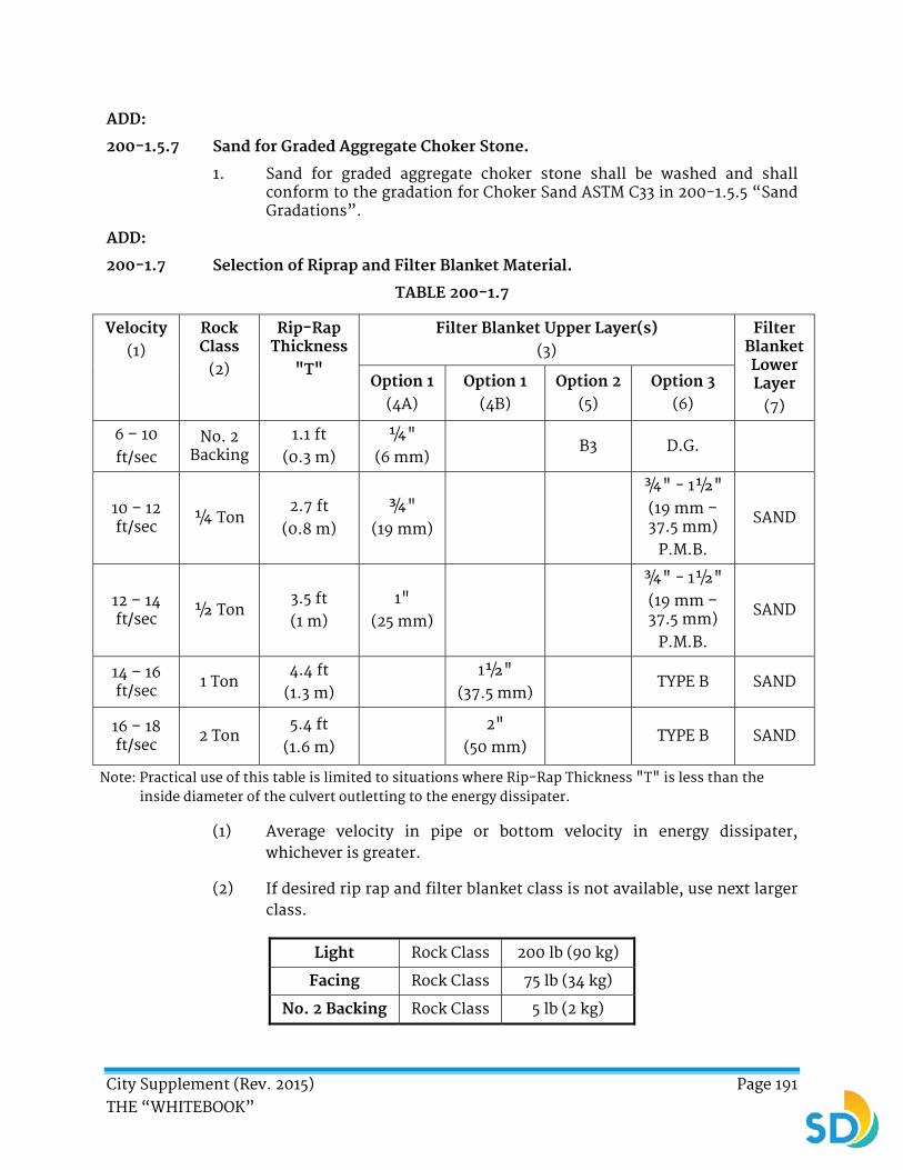
City Supplement (Rev. 2015) Page 191 THE “WHITEBOOK”
ADD:
200-1.5.7 Sand for Graded Aggregate Choker Stone.
1. Sand for graded aggregate choker stone shall be washed and shall conform to the gradation for Choker Sand ASTM C33 in 200-1.5.5 “Sand Gradations”.
ADD:
200-1.7 Selection of Riprap and Filter Blanket Material.
TABLE 200-1.7
Velocity (1)
Rock Class
(2)
Rip-Rap Thickness
"T"
Filter Blanket Upper Layer(s) (3)
Filter Blanket Lower Layer
(7)
Option 1 (4A)
Option 1 (4B)
Option 2 (5)
Option 3 (6)
6 – 10 ft/sec
No. 2 Backing
1.1 ft (0.3 m)
¼" (6 mm)
B3 D.G.
10 – 12 ft/sec ¼ Ton
2.7 ft (0.8 m)
¾" (19 mm)
¾" - 1½" (19 mm – 37.5 mm)
P.M.B.
SAND
12 – 14 ft/sec ½ Ton
3.5 ft (1 m)
1" (25 mm)
¾" - 1½" (19 mm – 37.5 mm)
P.M.B.
SAND
14 – 16 ft/sec 1 Ton
4.4 ft (1.3 m)
1½"
(37.5 mm) TYPE B SAND
16 – 18 ft/sec
2 Ton 5.4 ft
(1.6 m)
2" (50 mm)
TYPE B SAND
Note: Practical use of this table is limited to situations where Rip-Rap Thickness "T" is less than the inside diameter of the culvert outletting to the energy dissipater.
(1) Average velocity in pipe or bottom velocity in energy dissipater, whichever is greater.
(2) If desired rip rap and filter blanket class is not available, use next larger class.
Light Rock Class 200 lb (90 kg)
Facing Rock Class 75 lb (34 kg)
No. 2 Backing Rock Class 5 lb (2 kg)

City Supplement (Rev. 2015) Page 192 THE “WHITEBOOK”
(3) Filter blanket thickness = 1 foot (305 mm) or "T", whichever is less.
(4A) Option 1 shall meet the requirements of Table 200-1.2(A) of the Standard Specifications for Public Works Construction.
(4B) Option 1 shall meet the requirements of Table 200-1.4(B) of the Standard Specifications for Public Works Construction.
(5) Option 2 shall meet the asphalt concrete requirements of Table 400-4.3(C) of the Standard Specifications for Public Works Construction.
(6) D.G. = Disintegrated Granite per Table 200-2.7.2(A) of the Standard Specifications for Public Works Construction (0.04 inch to 0.39 inch) (1 mm to 10 mm).
P.M.B. = Processed Miscellaneous Base per 200-2.5, “Processed Miscellaneous Base”, of the Standard Specifications for Public Works Construction.
TYPE B = Type B bedding material shall conform to the requirements for ½ inch (12.5 mm) crushed rock or No. 4 concrete aggregate in 200-1, “Rock Products”, Table 200-1.2.1 (A) or Table 200-1.4 (B), of the Standard Specifications for Public Works Construction.
(7) Sand = 25% passing No. 200 sieve (75% retained).
200-2.1 General. DELETE in its entirety and SUBSTITUTE with the following:
1. Base or subbase materials shall be classified in the order of preference as follows:
a) Crushed Aggregate Base
b) Crushed Miscellaneous Base
c) Processed Miscellaneous Base
d) Class 2 Aggregate Base
e) Disintegrated Granite Base
f) Select Subbase
ADD:
200-2.9 Class 2 Aggregate Base.
200-2.9.1 General.
1. Class 2 Aggregate Base shall consist of broken or crushed asphalt, concrete, Portland cement concrete, railroad ballast, crushed porcelain material, crushed rock, rock dust, brick, or natural material. The material shall be free from organic matter and other deleterious substances, and shall be of such nature that it can be compacted readily under watering and rolling to form a firm, stable base.
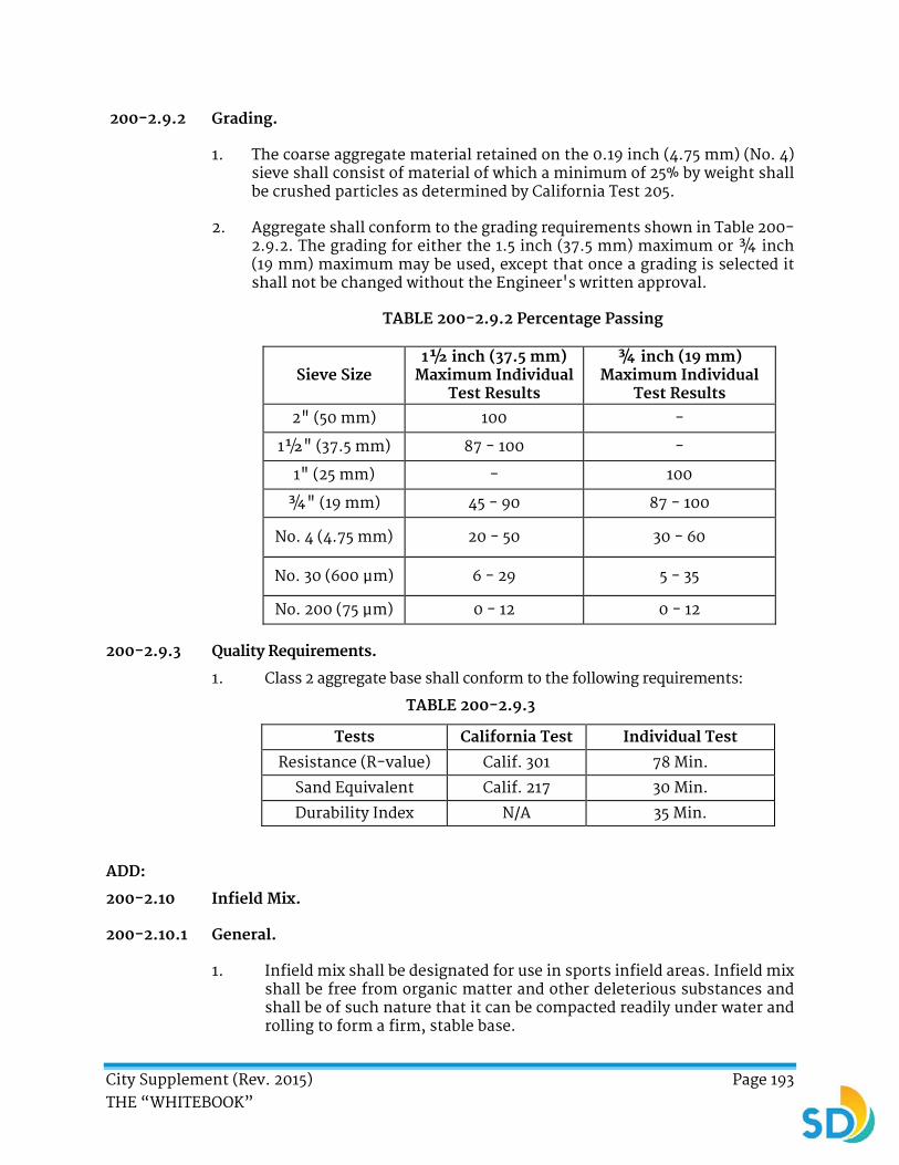
City Supplement (Rev. 2015) Page 193 THE “WHITEBOOK”
200-2.9.2 Grading.
1. The coarse aggregate material retained on the 0.19 inch (4.75 mm) (No. 4) sieve shall consist of material of which a minimum of 25% by weight shall be crushed particles as determined by California Test 205.
2. Aggregate shall conform to the grading requirements shown in Table 200-2.9.2. The grading for either the 1.5 inch (37.5 mm) maximum or ¾ inch (19 mm) maximum may be used, except that once a grading is selected it shall not be changed without the Engineer's written approval.
TABLE 200-2.9.2 Percentage Passing
Sieve Size 1½ inch (37.5 mm)
Maximum Individual Test Results
¾ inch (19 mm) Maximum Individual
Test Results
2" (50 mm) 100 -
1½" (37.5 mm) 87 - 100 -
1" (25 mm) - 100
¾" (19 mm) 45 - 90 87 - 100
No. 4 (4.75 mm) 20 - 50 30 - 60
No. 30 (600 μm) 6 - 29 5 - 35
No. 200 (75 μm) 0 - 12 0 - 12
200-2.9.3 Quality Requirements.
1. Class 2 aggregate base shall conform to the following requirements:
TABLE 200-2.9.3
Tests California Test Individual Test
Resistance (R-value) Calif. 301 78 Min.
Sand Equivalent Calif. 217 30 Min.
Durability Index N/A 35 Min.
ADD:
200-2.10 Infield Mix.
200-2.10.1 General.
1. Infield mix shall be designated for use in sports infield areas. Infield mix shall be free from organic matter and other deleterious substances and shall be of such nature that it can be compacted readily under water and rolling to form a firm, stable base.
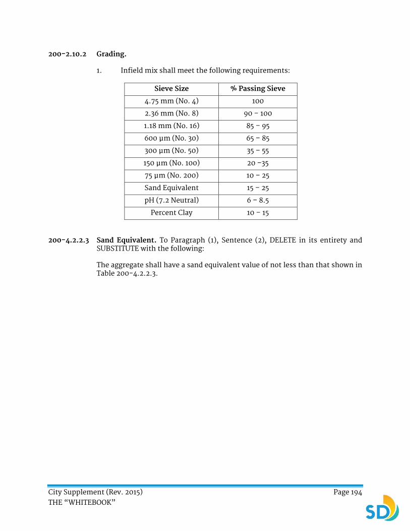
City Supplement (Rev. 2015) Page 194 THE “WHITEBOOK”
200-2.10.2 Grading.
1. Infield mix shall meet the following requirements:
Sieve Size % Passing Sieve
4.75 mm (No. 4) 100
2.36 mm (No. 8) 90 – 100
1.18 mm (No. 16) 85 – 95
600 μm (No. 30) 65 – 85
300 μm (No. 50) 35 – 55
150 μm (No. 100) 20 –35
75 μm (No. 200) 10 – 25
Sand Equivalent 15 – 25
pH (7.2 Neutral) 6 – 8.5
Percent Clay 10 – 15
200-4.2.2.3 Sand Equivalent. To Paragraph (1), Sentence (2), DELETE in its entirety and SUBSTITUTE with the following:
The aggregate shall have a sand equivalent value of not less than that shown in Table 200-4.2.2.3.

City Supplement (Rev. 2015) Page 195 THE “WHITEBOOK”
SECTION 201 - CONCRETE, MORTAR, AND RELATED MATERIALS
201-1.1.2 Concrete Specified by Class and Alternate Class. ADD the following:
1. Monolithic curb and pavement shall not be allowed.
To Table 201-1.1.2, REVISE the following:
1. Concrete class for “Concrete Pavement (not integral with curb)”, DELETE “520-A-2500” and SUBSTITUTE with “560-B-3250”.
2. Concrete class for “Sidehill Surface Drainage Facilities”, DELETE “500-C-2500” and SUBSTITUTE with “520-C-2500”.
3. Concrete class for “Fence and Guardrail Post Foundations”, DELETE “500-C-2500” and SUBSTITUTE with “520-C-2500”.
201-1.1.6.3 Mix Design. ADD the following:
1. The maximum water to cementitious ratio shall be 0.3 lb/lb (136 g/g), unless otherwise specified in the Special Provisions.
201-1.2.1 Cement. DELETE in its entirety and SUBSTITUTE with the following:
1. Cement to be used or furnished shall be low alkali and shall be either Type I or Type II Portland Cement conforming to ASTM C 150, or Type IP (MS) portland-pozzolan cement conforming to ASTM C595, unless otherwise specified in the Special Provisions.
2. You shall furnish a Certificate of Compliance for the cement.
3. Cement shall be stored to protect against contamination and moisture. Should any cement show evidence of contamination or be otherwise unsuitable, the Engineer may reject it and require that it be removed from the site.
4. Cement used in concrete for any individual structure shall be of the same brand and type, unless otherwise approved by the Engineer.
201-1.4.3 Transit Mixers. ADD the following:
1. Time and date of batching shall be machine stamped.
201-9 CEMENT TREATED BASE (CTB). DELETE in its entirety and SUBSTITUTE with the following:
201-9 CEMENT TREATED BASE (CTB).
201-9.1 General.
1. CTB shall consist of a mixture of untreated base material, a minimum of 2% Portland Cement by weight of dry aggregate, and water mixed at a

City Supplement (Rev. 2015) Page 196 THE “WHITEBOOK”
central mixing plant. Aggregate shall not exceed 120°F (11°C) at time of mixing. Water added shall be at or near optimum as determined by ASTM D 1557, Method C.
201-9.2 Materials.
201-9.2.1 Untreated Base Material.
1. Untreated base material to be treated shall be crushed aggregate base conforming to 200-2.2, crushed miscellaneous base conforming to 200-2.4, or pulverized miscellaneous base conforming to 200-2.8, except as modified herein.
2. Material shall be uniformly graded and shall conform to the following gradation:
Sieve Size % Passing Sieve
1" (25 mm) sieve 90 – 100
3/8" (9.5 mm) sieve 65 – 85
No. 4 (4.75 mm) sieve 45 – 65
No. 30 (600 μm) sieve 15 – 35
No. 200 (75 μm) sieve 3 – 15
Sand Equivalent 30 minimum
201-9.2.2 Portland Cement.
1. Portland cement shall be Type II/V conforming to 201-1.2.1, “Cement”. Supplementary cementitious materials shall not be substituted for Portland cement.
201-9.2.3 Water.
1. Water shall conform to 201-1.2.3, “Water”.
201-9.3 Mix Design(s).
1. The materials shall be tested and the mix design(s) developed in accordance with ASTM D1557. Compressive strength shall be determined in accordance with ASTM D1633, Method A or Caltrans Test Method 312, part V except test specimens shall be compacted in accordance with ASTM D1557, Method A or B or Caltrans Test Method 312, part III section D using split compaction mold, no tamping and compression load shall be 2000 psi.

City Supplement (Rev. 2015) Page 197 THE “WHITEBOOK”
2. The mix design(s) shall show the following:
a) The amount and gradation of the base material to be treated.
b) The amount and type of Portland cement.
c) The amount of water.
d) The required 7 Day compressive strength shall not be less than 400 psi.
201-9.4 Mixing.
1. Mixing shall conform to 201-8.4, “Mixing”.
201-9.5 Transporting.
1. Transporting shall conform to 201-8.5, “Transporting”.
201-9.6 Acceptance.
1. Acceptance of CTB mixtures produced at a central mixing plant shall be based on conformance to the Specifications.
ADD:
201-10 MANHOLES (MHs).
201-10.1 Pre-fabricated Manhole Bases (PMB).
1. If Prefabricated Manhole Base is shown on the Plans and if the MH is modified or placed at a new location because of a design change either in the vertical or horizontal position and the PMB does not meet the design criteria, you shall order a new PMB that complies with the modified alignment, location, or both. The City will compensate you for the base, restocking costs, and other related costs.
2. PMB may be allowed, when not shown on the Plans, if you assume all the risk and additional costs of the MH relocation as a result of unforeseen conditions or design changes. If the MH is modified or placed at a new location because of a design change either in the vertical or horizontal position and the PMB does not meet the design criteria, you shall order a new PMB that complies with the modified alignment and location. Otherwise, you shall replace the PMB with a cast in place base at no additional cost to the City.
3. If the PMB channels do not have the proper slopes or configurations as shown on the Plans or if the installation is not in compliance with the Contract requirements or the manufacturer’s recommendations, the PMB will be rejected by the Engineer and you shall cast a new base in place at no additional cost to the City.

City Supplement (Rev. 2015) Page 198 THE “WHITEBOOK”
201-10.2 Polymer Mortar.
1. The following products shall be acceptable for use in manhole riser joints:
Material Manufacturer
490 Epoxy Putty Engard Coatings, Huntington Beach, CA
Sikadur 31 Hi-Mod Gel Sika Corporation, Santa Fe Springs, CA
Sikadur 32 Hi-Mod Gel Sika Corporation, Santa Fe Springs, CA
CS-102 Butyl Gaskets (rope form) Concrete Sealants, New Carlisle, OH
201-10.3 Polyurethane Coating.
1. The epoxy primer and polyurethane liner shall be manufactured as listed on the City’s AML or approved equal.
2. The color shall be white or beige. You shall submit complete manufacturer specifications, application procedures, and references for review and approval.
201-10.4 Exterior Waterproofing for Manholes.
1. The coal tar emulsion shall be Kopper-Bitumastic Super Service Black or approved equal. Application of this material shall be in accordance with the manufacturer’s instructions and these specifications.

City Supplement (Rev. 2015) Page 199 THE “WHITEBOOK”
SECTION 202 - MASONRY MATERIALS
ADD:
202-4 PERMEABLE INTERLOCKING CONCRETE PAVERS.
202-4.1 General.
1. Permeable interlocking concrete pavers shall consist of the paving unit, joint fill and bedding aggregate, base aggregate, and subbase aggregate.
202-4.2 Materials.
202-4.2.1 Permeable Interlocking Concrete Paver.
1. All paver material shall comply with ASTM C 936. Paver color pigment material shall comply with ASTM C 979. For vehicular applications, the minimum allowable paver thickness shall be 31/8 inch (80 mm). For pedestrian applications the minimum allowable paver thickness shall be 2 3/8 inch (60 mm). The joints and/or openings shall comprise a minimum of 5% of the paver surface.
202-4.2.2 Crushed Stone Joint Filler and Bedding.
1. The joint filler and bedding material shall conform to 200-1, “Rock Products”. The gradation shall conform to Table 200-1.2.1 (A), ASTM No. 8. When the joints are narrow, gradation permitted shall conform to Table 200-1.2.1 (A). ASTM No. 89 or ASTM No. 9. All substitutions shall be approved in writing by the Engineer.
202-4.2.4 Base Aggregate.
1. The base aggregate shall conform to 200-1, “Rock Products”. The aggregate gradation shall conform to Table 200-1.2.1 (A), AASHTO No. 57.
202-4.2.5 Subbase Aggregate.
1. The subbase aggregate shall conform to 200-1, “Rock Products”. The aggregate gradation shall conform to Table 200-1.2.1 (A), ASTM No. 2.
202-4.3 Storage.
1. Store materials in protected areas such that they are kept free from mud, dirt, and other foreign materials. Store concrete paver cleaners and sealers per the manufacturer’s instructions.

City Supplement (Rev. 2015) Page 200 THE “WHITEBOOK”
SECTION 203 - BITUMINOUS MATERIALS
203-1.6 Measurement and Payment. ADD the following:
1. The payment for paving asphalt shall be included in the item of Work to which its use is incidental, unless a Bid item has been provided.
203-2.6 Measurement and Payment. ADD the following:
1. The payment for liquid asphalt shall be included in the item of Work to which its use is incidental, unless a Bid item has been provided.
203-3.4.4.1 General. To Paragraph (2), DELETE in its entirety and SUBSTITUTE with the following:
The entirety of the crumb rubber shall:
a) Be granulated scrap tire rubber free from fabric, wires, and other contaminants.
b) Be dry and free flowing.
c) Have a specific gravity between 1.15 and 1.20.
d) Have a gradation of 100% passing the No. 16 (1.18 mm) sieve, 95% passing the No. 20 (900 μm) sieve, and a maximum of 1 percent passing the No. 200 (75 μm) sieve.
e) Be a product of recycled material from the City if unavailable from the San Diego County region.
203-3.4.4 Rubberized Polymer Modified Emulsion (RPME). DELETE in its entirety and SUBSTITUTE with the following:
203-3.4.4 RUBBER POLYMER MODIFIED SLURRY (RPMS).
203-3.4.4.1 General.
1. Rubber polymer modified slurry (RPMS) is a crumb rubber asphalt slurry-seal surface treatment. RPMS shall be a stable mixture of asphaltic emulsion, mineral aggregate, set-control additives, specially produced and graded crumb rubber, polymer, mineral fillers, carbon black, and water. The materials for RPMS shall conform to 203-5.4, “Emulsion-Aggregate Slurry (EAS)” and these specifications. Mixing and spreading of RPMS shall be as described in 302-4.12, “Rubber Polymer Modified Slurry (RPMS)”.
2. RPMS may be used when specified in the Special Provisions.

City Supplement (Rev. 2015) Page 201 THE “WHITEBOOK”
203-3.4.4.2 Materials.
1. The ingredients of RPMS immediately prior to the mixing shall conform to the following:
a) Asphaltic emulsion shall be a quick-set type and shall conform to the requirements of CQS-1h and to the following requirements in accordance with the specified test methods:
Quality Tests for Emulsion Test Requirements
AASHTO T59 Residue after Distillation
60% min. ASTM D244
Quality Tests for Residue Test Requirements
AASHTO T49 Penetration at
77° F (25° C) 40% - 90%
ASTM D2397
b) Quick setting Type CQS-1h Asphaltic Emulsion shall test positive for Particle Charge when tested in accordance with the applicable ASTM test designation. If the Particle Charge Test result is inconclusive, the asphaltic emulsion shall meet a pH requirement of 6.7 maximum.
c) Water shall be potable and of such quality that the asphalt will not separate from the emulsion before the application of slurry seal.
d) If necessary for workability, a set-control agent that will not adversely affect the RPMS material may be added.
e) Polymer additive shall be SBR Latex or approved equal, which is added at a minimum of 2% by weight of the asphaltic emulsion.
f) Crumb Rubber.
i. Crumb rubber shall be ambient granulated or ground from whole passenger tires, truck tires, or a combination only in conformance with the requirements indicated in Tables 203-3.4.4.2 (A), 203-3.4.4.2 (B), and 203-3.4.4.2 (C).
ii. Un-curing or de-vulcanized rubber shall not be acceptable. Rubber tire buffing from either recapping or
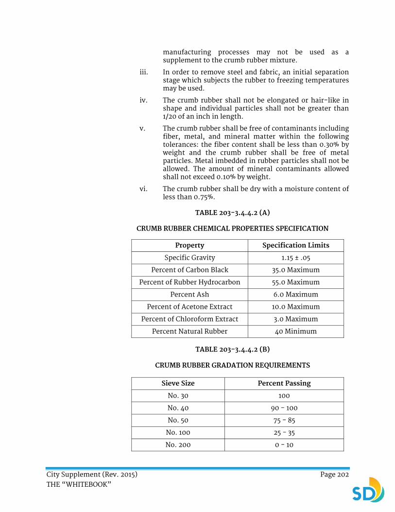
City Supplement (Rev. 2015) Page 202 THE “WHITEBOOK”
manufacturing processes may not be used as a supplement to the crumb rubber mixture.
iii. In order to remove steel and fabric, an initial separation stage which subjects the rubber to freezing temperatures may be used.
iv. The crumb rubber shall not be elongated or hair-like in shape and individual particles shall not be greater than 1/20 of an inch in length.
v. The crumb rubber shall be free of contaminants including fiber, metal, and mineral matter within the following tolerances: the fiber content shall be less than 0.30% by weight and the crumb rubber shall be free of metal particles. Metal imbedded in rubber particles shall not be allowed. The amount of mineral contaminants allowed shall not exceed 0.10% by weight.
vi. The crumb rubber shall be dry with a moisture content of less than 0.75%.
TABLE 203-3.4.4.2 (A)
CRUMB RUBBER CHEMICAL PROPERTIES SPECIFICATION
Property Specification Limits
Specific Gravity 1.15 ± .05
Percent of Carbon Black 35.0 Maximum
Percent of Rubber Hydrocarbon 55.0 Maximum
Percent Ash 6.0 Maximum
Percent of Acetone Extract 10.0 Maximum
Percent of Chloroform Extract 3.0 Maximum
Percent Natural Rubber 40 Minimum
TABLE 203-3.4.4.2 (B)
CRUMB RUBBER GRADATION REQUIREMENTS
Sieve Size Percent Passing
No. 30 100
No. 40 90 - 100
No. 50 75 - 85
No. 100 25 - 35
No. 200 0 - 10
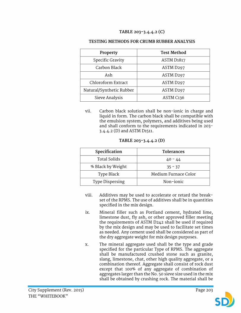
City Supplement (Rev. 2015) Page 203 THE “WHITEBOOK”
TABLE 203-3.4.4.2 (C)
TESTING METHODS FOR CRUMB RUBBER ANALYSIS
Property Test Method
Specific Gravity ASTM D1817
Carbon Black ASTM D297
Ash ASTM D297
Chloroform Extract ASTM D297
Natural/Synthetic Rubber ASTM D297
Sieve Analysis ASTM C136
vii. Carbon black solution shall be non-ionic in charge and liquid in form. The carbon black shall be compatible with the emulsion system, polymers, and additives being used and shall conform to the requirements indicated in 203-3.4.4.2 (D) and ASTM D1511.
TABLE 203-3.4.4.2 (D)
Specification Tolerances
Total Solids 40 - 44
% Black by Weight 35 - 37
Type Black Medium Furnace Color
Type Dispersing Non-ionic
viii. Additives may be used to accelerate or retard the break-set of the RPMS. The use of additives shall be in quantities specified in the mix design.
ix. Mineral filler such as Portland cement, hydrated lime, limestone dust, fly ash, or other approved filler meeting the requirements of ASTM D242 shall be used if required by the mix design and may be used to facilitate set times as needed. Any cement used shall be considered as part of the dry aggregate weight for mix design purposes.
x. The mineral aggregate used shall be the type and grade specified for the particular Type of RPMS. The aggregate shall be manufactured crushed stone such as granite, slang, limestone, chat, other high quality aggregate, or a combination thereof. Aggregate shall consist of rock dust except that 100% of any aggregate of combination of aggregates larger than the No. 50 sieve size used in the mix shall be obtained by crushing rock. The material shall be

City Supplement (Rev. 2015) Page 204 THE “WHITEBOOK”
free from vegetable matter and other deleterious substances. The aggregate shall be free of caked lumps and oversized particles. The aggregate shall also conform to the following requirements in Table 203-3.4.4.2 (E).
TABLE 203-3.4.4.2 (E)
Test California Test Requirements
Sand Equivalent 217 45 min.
Durability Index 229 55 min.
203-3.4.4.3 Composition and Grading.
1. The percentage composition by weight of the aggregate shall conform to the requirements indicated in the tables below when determined by California Test 202 and modified by California Test 105 when there is a difference in specific gravity of 0.20 or more between blends of different aggregates.
TABLE 203-3.4.4.3 (A)
TYPE I SLURRY SEAL GRADATION
Sieve Size Percentage Passing Stockpile Tolerance No.4 100 ± 5% No.8 90 - 100 ± 5% No.16 65 - 90 ± 5% No.30 40 - 60 ± 5% No.50 25 - 42 ± 4%
No.200 10 - 20 ± 2%
TABLE 203-3.4.4.3 (B)
TYPE II SLURRY SEAL GRADATION
Sieve Size Percentage Passing Stockpile Tolerance No.3/8 100 ± 5% No.4 90 - 100 ± 5% No.8 65 - 90 ± 5% No.16 45 - 70 ± 5% No.30 30 - 50 ± 5% No.50 18 - 36 ± 4%
No.100 10 - 24 ± 3% No.200 5 - 15 ± 2%
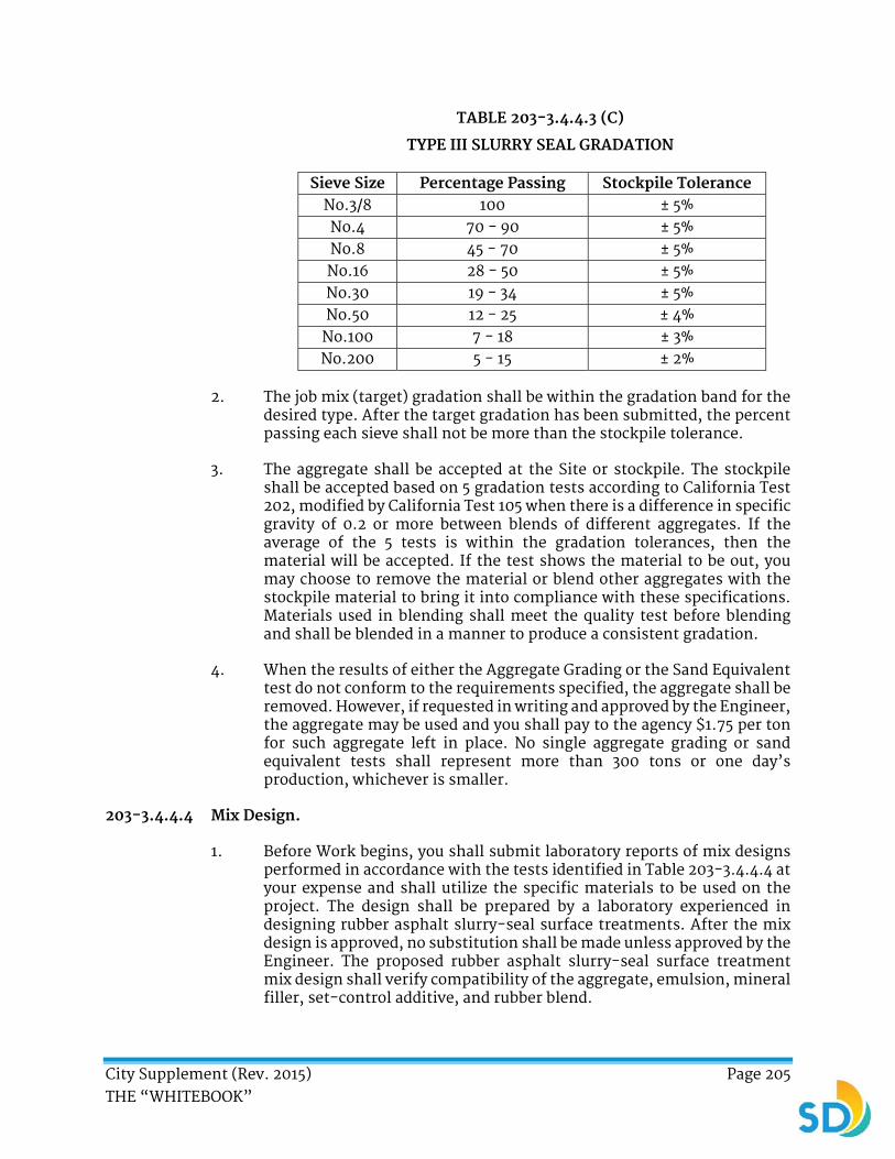
City Supplement (Rev. 2015) Page 205 THE “WHITEBOOK”
TABLE 203-3.4.4.3 (C)
TYPE III SLURRY SEAL GRADATION
Sieve Size Percentage Passing Stockpile Tolerance No.3/8 100 ± 5% No.4 70 - 90 ± 5% No.8 45 - 70 ± 5% No.16 28 - 50 ± 5% No.30 19 - 34 ± 5% No.50 12 - 25 ± 4%
No.100 7 - 18 ± 3% No.200 5 - 15 ± 2%
2. The job mix (target) gradation shall be within the gradation band for the desired type. After the target gradation has been submitted, the percent passing each sieve shall not be more than the stockpile tolerance.
3. The aggregate shall be accepted at the Site or stockpile. The stockpile shall be accepted based on 5 gradation tests according to California Test 202, modified by California Test 105 when there is a difference in specific gravity of 0.2 or more between blends of different aggregates. If the average of the 5 tests is within the gradation tolerances, then the material will be accepted. If the test shows the material to be out, you may choose to remove the material or blend other aggregates with the stockpile material to bring it into compliance with these specifications. Materials used in blending shall meet the quality test before blending and shall be blended in a manner to produce a consistent gradation.
4. When the results of either the Aggregate Grading or the Sand Equivalent test do not conform to the requirements specified, the aggregate shall be removed. However, if requested in writing and approved by the Engineer, the aggregate may be used and you shall pay to the agency $1.75 per ton for such aggregate left in place. No single aggregate grading or sand equivalent tests shall represent more than 300 tons or one day’s production, whichever is smaller.
203-3.4.4.4 Mix Design.
1. Before Work begins, you shall submit laboratory reports of mix designs performed in accordance with the tests identified in Table 203-3.4.4.4 at your expense and shall utilize the specific materials to be used on the project. The design shall be prepared by a laboratory experienced in designing rubber asphalt slurry-seal surface treatments. After the mix design is approved, no substitution shall be made unless approved by the Engineer. The proposed rubber asphalt slurry-seal surface treatment mix design shall verify compatibility of the aggregate, emulsion, mineral filler, set-control additive, and rubber blend.

City Supplement (Rev. 2015) Page 206 THE “WHITEBOOK”
TABLE 203-3.4.4.4
Test Description Specification
ISSA T-106 Slurry Seal Consistency Pass
ISSA TB-109 Excess Asphalt 50 grams/ft2 maximum
ISSA TB-100 (Type I)
The Wet Track Abrasion 50 grams/ ft2 maximum
ISSA TB-100 (Type II)
The Wet Track Abrasion
60 grams/ ft2 maximum
ISSA TB-100 (Type III)
The Wet Track Abrasion
60 grams/ ft2 maximum
ISSA TB-113 Mixing Time Controllable to
150 seconds minimum
ISSA TB-114 The Wet Stripping Pass
2. The Mixing Time test shall be done at the highest temperatures expected during construction. The original lab report shall be signed by the laboratory that performed the mix design and shall show the results of the tests on individual materials. The report shall clearly show the proportions of aggregate, mineral filler (minimum and maximum), water (minimum and maximum), additive (s) (usage), asphalt emulsion, and asphalt rubber blend based on the dry weight of the aggregate.
3. Component materials used in the mix design shall be representative of your proposed materials. The percentage of each individual material required shall be shown in the laboratory report. Adjustments may be required during the construction based on field conditions.
4. The component materials shall be within the following limits:
a) Residual Asphalt Type I, 10% - 16% based on dry weight of aggregate.
b) Residual Asphalt Type II, 7.5% - 13.5% based on dry weight of aggregate.
c) Residual Asphalt Type III, 6.5% - 12% based on dry weight of aggregate.
d) The crumb rubber will be added to the rubberized slurry mix at a rate of 5% by volume to the asphalt cement.
e) Polymer additive shall be added at 2% of finished emulsion.
f) Carbon Black shall be added at 1.3% to 2% of the finished emulsion.
City Supplement (Rev. 2015) Page 207 THE “WHITEBOOK”
g) Mineral filler shall be 0.5% - 2.0% (if required by mix design) based on dry weight of aggregate.
h) Additives, as needed.
i) Water, as needed to achieve proper mix consistency (total mix liquids shall not exceed the loose aggregate voids).
203-3.5 Certificate of Compliance. ADD the following:
1. Test reports and certifications shall be made in accordance with 4-1.4, “Test of Materials”; 203-1.3, “Test Reports and Certification”; and 302-4.2.1, “General”.
ADD:
203-3.9 Payment.
1. The payment for emulsified asphalt shall be included in the item of Work to which its use is incidental, unless a Bid item has been provided.
203-5.2 Mix Design. ADD the following:
1. The completed slurry shall have a minimum skid resistance of 40 when tested per the State of California Department of Transportation California Test 342.
203-5.3.1 General. ADD the following:
1. The aggregate shall be from Chandler Aggregates, Inc. or equal. The aggregate shall have a specific gravity of no less than 2.60.
2. Type I slurry aggregate shall be allowed. The aggregate shall be of such character that it will not disintegrate from the action of air, water, or the conditions to be met in handling and placing and shall have a specific gravity of no less than 2.60. It shall have a minimum sand equivalent of 55.
203-6.1 General. ADD the following:
1. The content of paving asphalt recovered from the RAP shall be determined in conformance with California Test 382 each day RAP is used or as approved by the Engineer.
203-6.3.1 General. ADD the following:
1. You shall submit for approval, mix designs for C2 PG 64-10 (½ inch) (12.5 mm) and B3 PG 64-10 (¾ inch) (19 mm) asphalt concrete. Asphalt concrete mix designs shall be submitted to the City Materials Testing Laboratory for approval.

City Supplement (Rev. 2015) Page 208 THE “WHITEBOOK”
2. Once the City has approved a mix design, the asphalt binder content shall be within 0.5% of the identified target binder contents for each mix design submitted.
203-6.4.3 Combined Aggregates and Reclaimed Asphalt Pavement (RAP). To Subsection “a”, DELETE in its entirety and SUBSTITUTE with the following:
a) The combined aggregates shall have a minimum sand equivalent of 50 when tested in accordance with California Test 217 or ASTM D2419.
203-6.5.4 Composition and Grading. To Table 203-6.5.4 (A), Class B2 and Class B3, DELETE in its entirety and SUBSTITUTE with the following:
CLASS B2 B3
Sieve Size Individual Test Result
Moving Average
Individual Test Result
Moving Average
1" (25.0 mm) 100 100 100 100
3/4" (19.0 mm) 87 - 100 90 - 100 90 - 100 95 - 100
1/2" (12.5 mm) 75 - 95 80 - 90 85 - 100 85 - 95
3/8" (9.5 mm) 50 - 80 60 - 75 60 - 84 65 - 80
No. 4 (4.75 mm) 30 - 60 40 - 55 40 - 60 45 - 60
No. 8 (2.36 mm) 22 - 44 27 - 40 24 - 50 30 - 45
No. 30 (600 μm) 8 - 26 12 - 22 11 - 29 14 - 25
No. 200 (75 μm) 1 - 8 3 - 6 1 - 9 3 - 7
Asphalt Binder % 4.6 - 6.0 4.6 - 6.0

City Supplement (Rev. 2015) Page 209 THE “WHITEBOOK”
SECTION 206 - MISCELLANEOUS METAL ITEMS
ADD:
206-3.3.5 Underdrain Cleanout Lid (for other areas).
1. Cleanout lids for cleanouts in the road, sidewalk, or any other area where water is not expected to pool shall be Alhambra Foundry A-2302-B cast iron water-tight cover and frame that is rated for traffic applications or approved equal.
2. The cleanout lid shall have a clear opening of 8 inches (203 mm) and have an overall diameter of 13 inches (330 mm). The frame shall be 1 inch (25 mm) deep. The frame shall be set into the concrete collar and the lid shall seat firmly into the frame without rocking and shall be flush with the surface. Lock screws shall be provided to lock lid to frame. The cleanout lid shall be stamped “SD STORM DRAIN”.
ADD:
206-7 STREET NAME SIGN.
1. Street name signs shall conform to the requirements of Standard Drawing SDM-102, “Street Name Sign”.

City Supplement (Rev. 2015) Page 210 THE “WHITEBOOK”
SECTION 207 - GRAVITY PIPE
ADD the following:
1. Pipe installed as sewer main shall be Vitrified Clay (Extra Strength) or Polyvinyl Chloride (PVC). PVC pipe shall be SDR-35 unless otherwise designated on the plans.
2. Pipe and fittings for house connection sewer (laterals) shall be Vitrified Clay (Extra Strength), PVC, or Acrylonitrile-Butadiene-Styrene (ABS) solid wall pipe.
3. Asbestos cement pipe shall not be acceptable.
207-2.9.1 General. ADD the following:
1. The basis for acceptance shall be by the D-load bearing strength test, compliance with these Specifications, and inspection of the pipe manufacture and inspection of the completed pipe.
207-17.1 General. DELETE in its entirety and SUBSTITUTE with the following:
1. The ASTM Designation, SDR, pipe stiffness, and type of joint shall be specified on the plans and/or specifications.
2. House Connection Sewer Laterals shall use glued, gasketed, or stainless steel shielded couplings listed on the Wastewater Approved Materials List or approved equal.
207-17.2.2 Cell Classification. ADD the following:
1. PVC pipes for storm drains and tertiary treated recycled water (“purple pipe”) that cross existing potable water mains and have a vertical clearance of less than 12 inches (305 mm), or more if indicated on the plans, shall have a PVC cell classification of 12454 meeting AWWA C900 and CL200 and meeting the requirements of DR14. No joints are permitted within 4 feet (1.2 m) of the water line crossing.
207-17.3.2 Elastomeric Gasket Joints. DELETE in its entirety and SUBSTITUTE with the following:
1. Pipe with gasketed joints shall be manufactured with a socket configuration which shall prevent improper installation of the gasket and shall ensure that the gasket remains in place during the joint operation.
2. The gasket shall be polyurethane or synthetic rubber with equal or greater resistance to solvency, chemical, or biological attack and shall conform to the requirements of 208-1.2, “Installation Time Limit” and 208-4, “Gaskets For Thermoplastic Pipe”.
City Supplement (Rev. 2015) Page 211 THE “WHITEBOOK”
207-17.4.2 Acceptance. DELETE in its entirety and SUBSTITUTE with the following:
1. The basis for acceptance shall be the inspection of pipe, fittings, and couplings, the tests specified in 207-17.4, “Test Requirements”, and compliance with the Specifications.
2. When the pipe is delivered to the Work site, the Engineer may require additional testing to determine conformance with the requirements of pipe flattening, impact resistance, pipe stiffness, and extrusion quality.
3. You shall provide information to the Engineer verifying that the quantity of pipe, the manufacturing and delivery date, and the pipe stored is the same material documented on the Certificate of Compliance.
4. You shall provide explanation of pipe markings and shall include manufacturing date and location.
5. If the pipe will not be installed within 6 months of manufacture date, you shall protect the pipe from environmental degradation (UV rays and sunlight) in accordance with the manufacturer’s recommendations.
6. You shall insure that the PVC pipe is stored locally within 25 mile (40 km) radius and that the Engineer has reasonable access to the pipe at the storage location.
7. The stored pipe shall not be removed from storage for purposes other than for the Project without the Engineer’s approval.
8. PVC pipe handled and stored in accordance with these specifications will be acceptable for installation for up to 2 years from the date of manufacture without repeat testing.
9. The Engineer may process payment for stored PVC pipes in accordance with 9-3.3.1, “Payment for Stored Materials on Site” and 9-3.3.1.2, “Payment for Stored Materials Offsite”.
10. For PVC pipe older than 6 months from date of manufacture as evidenced by pipe markings:
a) Prior to installation of PVC pipe, you shall submit to the Engineer a current (no older than 60 Days) complete set of third party independent test results for each separate lot of pipe consisting of:
i. Flattening capability conforming to ASTM D2412.
ii. Extrusion quality by the acetone-immersion method as specified in ASTM D2152.
b) Test results shall identify the pipe by its markings as provided by the manufacturer.
City Supplement (Rev. 2015) Page 212 THE “WHITEBOOK”
c) PVC pipe installation may not proceed prior to your submittal of test results and prior to the written acceptance by the Engineer.
d) PVC pipe tested as outlined above shall be accepted for installation for a maximum of 6 months from the date of testing unless it is stored and handled in accordance with these specifications immediately after testing.
e) PVC pipe that is not stored locally within a 25 mile (40 km) radius of the Site or where the Engineer does not have reasonable access to verify storage and handling shall be retested in accordance with these specifications within 60 Days prior to installation in accordance with 207-15.6, “Installation Time Limit”.
ADD:
207-17.6 Fusible Non-pressure Polyvinylchloride (PVC) Pipe.
207-17.6.1 General.
1. This subsection specifies fusible polyvinylchloride (PVC) pipe for sewer mains and laterals when used for horizontal directional drilling and where shown on the Plans.
207-17.6.2 Material.
1. Fusible PVC plastic material for pipe shall conform to ASTM D3034 or ASTM F679, and ASTM D1784 cell classification 12454. Fusible PVC pipe shall be tested at the extrusion facility for properties required to meet all applicable parameters.
2. Fusible PVC pipe shall be extruded with plain ends. The ends shall be square to the pipe and free of any bevel or chamfer. There shall be no bell or gasket of any kind incorporated into the pipe.
3. Pipe shall be homogeneous throughout and be free of visible cracks, holes, foreign material, blisters, or other deleterious faults. Any length of pipe showing a crack or which has received a blow that may have caused an incident fracture, even though no such fracture can be seen, shall be marked as rejected and removed from the Site immediately. Damaged areas or possible areas of damage may be removed by cutting out and removing the suspected incident fracture area. Limits of the acceptable length of pipe shall be determined by the Engineer.
4. Any scratch or gouge greater than 10% of the wall thickness shall be considered significant and will be rejected unless determined acceptable by the Engineer.
5. Pipe segments shall be butt fused together in accordance with the manufacturer’s requirements.

City Supplement (Rev. 2015) Page 213 THE “WHITEBOOK”
6. Fusible PVC pipe shall be manufactured with 100% virgin resin in a standard 20 feet (6.1 m), 30 feet (9.1 m), or 40 feet (12.2 m) nominal length with the following general characteristics:
a) Color: Green (for wastewater applications).
b) SDR: 18 minimum, unless otherwise shown on the plans.
207-17.6.2.1 Submittals.
1. You shall submit the following product data from the pipe supplier or fusion provider:
a) Name of the pipe manufacturer and a list of the materials to be provided by manufacturer. This shall include:
i. Pipe Size.
ii. Dimensionality.
iii. Pressure Class per applicable standard.
iv. Color.
v. Recommended Minimum Bending Radius.
vi. Recommended Maximum Safe Pull Force.
b) Written procedural documentation for piping products including proper handling and storage, installation, tapping, and testing.
c) Couplings to be utilized in the installation.
207-17.6.3 Connections for Gravity Sanitary Sewer Applications.
1. The following connections shall be used in conjunction with tie-ins to existing gravity sewer piping as shown on the Plans.
207-17.6.3.1 PVC Gasketed Push-on Couplings.
1. Acceptable couplings for joining fusible PVC pipe to other sections of fusible PVC pipe or other sections of PVC pipe shall include gasketed PVC with push-on type couplings.
207-17.6.3.2 Sleeve-type Couplings.
1. Sleeve-type mechanical couplings shall be manufactured for use with PVC pipe, and may be restrained or unrestrained as indicated on the drawings and in these specifications.
2. Acceptable sleeve-type mechanical pipe couplings shall be from the Wastewater Approved Materials List or an approved equal.

City Supplement (Rev. 2015) Page 214 THE “WHITEBOOK”
207-17.6.3.3 Expansion and Flexible Couplings.
1. Expansion-type mechanical couplings shall be manufactured for use with PVC pipe and may be restrained or unrestrained as shown on the Plans or required in these specifications.
2. Acceptable expansion-type mechanical pipe couplings shall be from the Wastewater Approved Materials List or an approved equal.
3. Acceptable flexible couplings shall be from the Wastewater Approved Materials List or an approved equal.
207-17.6.3.4 Connection Hardware.
1. Bolts and nuts shall be made of non-corrosive, high-strength, low-alloy steel having the characteristics specified in ANSI/AWWA C111/A21 regardless of any other protective coating.
207-17.6.4 Pipe Markings.
1. Delivered pipe markings shall include, as a minimum, the following:
a) Nominal size.
b) PVC.
c) Dimension Ratio, Standard Dimension Ratio or Schedule.
d) Extrusion production-record code.
e) Trademark or trade name.
f) Cell Classification.
g) ASTM D3034 or ASTM F679.
207-17.6.5 Handling and Storage.
1. The pipe shall be handled per manufacturer recommendations and stored at ambient temperature and protected from ultraviolet light degradation.
ADD:
207-17.7 Perforated PVC Plastic Pipe.
207-17.7.1 Materials of Underdrain Pipe.
1. Perforated plastic pipe shall be smooth-wall PVC plastic pipe or corrugated PVC plastic pipe with a smooth interior surface. All pipes shall comply with 207-17, “PVC Gravity Pipe”.

City Supplement (Rev. 2015) Page 215 THE “WHITEBOOK”
207-17.7.2 Perforation Requirements.
Hole Size 3/8 inch (9 mm) min.
Center to Center Spacing 5 inches (125 mm) max.
Row of Holes
4 holes per each row and all on the lower half of the pipe. There shall be 2 holes on each side of the
centerline of the pipe. 1 hole shall be at 45o from the centerline of the pipe and 1 hole shall be at 80o from
the centerline of the pipe as indicated on the Drawings.
207-17.8 Underdrain Cleanout.
207-17.8.1 General.
1. All underdrain cleanout PVC Plastic Pipe shall conform to 207-17, “PVC Gravity Pipe.
2. Underdrain cleanouts shall have watertight, vandal-proof caps.
207-19 POLYETHYLENE (PE) SOLID WALL GRAVITY PIPE. ADD the following:
1. PE pipe used in pipe bursting and horizontal directional drilling applications shall conform to SDR 17, unless otherwise shown on the Plans.
2. Pipe segments shall be butt fused together.
207-19.2 Material Composition.
1. PE pipe used in pipe bursting and horizontal directional drilling applications shall have a PPI rating of PE3408, when compounded. The pipe shall have a minimum cell classification of 345464E. Inner wall shall be light in color.

City Supplement (Rev. 2015) Page 216 THE “WHITEBOOK”
SECTION 209 - PRESSURE PIPE ADD the following:
1. Asbestos cement pipe shall not be acceptable.
209-1.1.2 Materials. ADD the following:
1. Fittings shall be mechanical joints. Bolt holes in the flanges of the mechanical joint fitting shall straddle the vertical centerline of the fitting.
2. Glands shall be made of ductile iron and shall be factory-stamped. The ductile iron used for the production of glands shall have a minimum elongation of 5%. Bolts shall be tee heads made of high-strength low-alloy steel or ductile iron in accordance with AWWA C111.
3. The pipe for threaded flange ductile-iron extension spools for above ground and vault shall be Class 53 minimum and cut to allow for ½ inch (12.5 mm) additional length for Flange x Flange and 0.25 inch (6 mm) additional length for Flange x Pipe End.
4. Machine tapered pipe thread (NPT) shall comply with ANSI B1.20.1 adapted to ductile-iron pipe outside diameters.
5. The threaded flange shall be dimensioned in accordance with USA Standard Taper Pipe and shall be attached to the machined pipe threads. The threaded flange shall be removed from the pipe and two-part epoxy thread sealant shall be applied to the pipe threads and the flange threads. Coal tar coating shall comply with AWWA C203 and epoxy coating shall comply with AWWA C213. The threaded flange shall be re-attached to the pipe threads and shall be machine tightened.
6. The threaded joint and spool assembly shall be hydrostatically tested 300 psi, stamped with the manufacturer’s mark indicating length, weight, and customer, and stenciled with “Tested at 300 PSI”.
7. Certification of Compliance with all specifications shall be furnished.
8. The outside surfaces of ductile iron pipe and fittings, including valves and appurtenances for buried service, shall be coated with one of the following:
a) 24 mils minimum dry film thickness (MDFT) liquid epoxy coating in accordance with AWWA C210. Coal tar epoxies shall not be used.
b) 24 mils MDFT Fusion Bonded Epoxy coating in accordance with AWWA C213 and AWWA C116.
c) A cold applied three-part system, 80 mils petroleum Wax Tape coating in accordance with AWWA C217
d) 24 mils MDFT 100% solids Polyurethane coating in accordance with AWWA C222.
9. Prior to coating, the iron surfaces shall be blast cleaned in accordance with the applicable National Association of Pipe Fabricators (NAPF) standard 500-03, “Surface Preparation Standard for Ductile Iron Pipe

City Supplement (Rev. 2015) Page 217 THE “WHITEBOOK”
and Fittings Receiving Special External Coatings and/or Special Internal Linings”. The entire coated surface shall be inspected with a holiday detector in accordance with National Association of Corrosion Engineers (NACE International) standard SP0188-2006, “Discontinuity (Holiday) Testing of New Protective Coatings on Conductive Substrates”.
10. For water facilities, fittings shall be lined with cement mortar and shall be seal-coated in accordance with AWWA C104/A21.4. Seal coat shall be NSF/ANSI 61 approved. The interior of bells shall be lined as specified in the Special Provisions. Cement lining shall be double thickness and shall use cement conforming to ASTM C150 Type II. For sewer facilities, internal epoxy linings may be required.
11. Non-cement mortar linings and coatings shall be holiday free on all surfaces of the fittings, including bells.
12. For buried use, all bare iron and steel components associated with ductile iron fittings such as bolts, thrust rods, flanges, and restraining components shall be coated with a three-part wax tape coating system in accordance with AWWA C217 regardless of the coating system applied to the fitting.
13. When soils have been determined to be in excess of 10,000 ohms-cm through resistivity testing as specified in the City of San Diego Sewer and Water Design Guidelines and as approved by the Engineer, the external surfaces of ductile iron pipe and fittings for general use may be coated with bituminous coating 1 mil (25 um) thick in accordance with AWWA C151 or AWWA C110. Polyethylene encasement shall be provided in accordance with AWWA C105. In the absence of such testing, special coatings in accordance with item 8 of 209-1.1.2, “Materials” shall apply.
209-2.2.1 Materials. To Table 209-2.2.1, “Lining and Exterior Coating (Required on exposed steel surfaces and ring joints)”, “Cement-Mortar Interior Lining and Exterior Coating”, DELETE in its entirety and SUBSTITUTE with the following:
Cement-Mortar Interior Lining (AWWA C205)
Pipe Size Lining Thickness
4 inch - 10 inch (100 mm - 250 mm) pipe ¼ inch (6 mm)
11 inch - 23 inch ( 275 mm - 575 mm) pipe 3/8 inch ( 9.5 mm)
24 inch – 36 inch (600 mm - 900 mm) pipe ½ inch (12.5 mm)
36 inch (900 mm) and Larger pipe ¾ inch (19.1 mm)
Conform to AWWA C205 using Type II/V cement.
Trim lining as necessary to allow full operation of butterfly or check valves at connections to steel pipe.
Line exposed portions of pipe interior with hand-applied epoxy conforming to 212-12, “Water and Sewer System Valves and Appurtenances”.
1 inch (25.4 mm) minimum coating thickness unless otherwise specified or if soil is identified as corrosive.
Trim coating 6 inch to 12 inch (152.4 mm to 304.8 mm) above grade on spools penetrating to daylight or vault interiors.
City Supplement (Rev. 2015) Page 218 THE “WHITEBOOK”
To Table 209-2.2.1, “Joints”, “Flanged Joint”, DELETE in its entirety and SUBSTITUTE with the following:
Joints Flanged Joint
Conform to AWWA C207. Flange joints identified on the plans to receive dielectric insulation kits shall have the flange bolt holes over-drilled per section 4.2.3 of AWWA C207. Faced and dimensioned in accordance with ASME/ANSI B16.5 for the pressure class shown on the Plans or specified in the Special Provisions.
209-4.3 PVC Pressure Water Pipe 4 inch to 12 inch (100 mm to 305 mm).
1. Pipe shall conform to the requirements of AWWA C900. Milled over all (MOA) PVC pipe having asbestos cement pipe size 8 inch (203.2 mm) through 12 inch (304.8 mm) may be used only where a shorter than standard length is needed to make a connection to the existing water main.
2. Design and installation shall comply with AWWA Manual M-23, “PVC Pipe Design and Installation”, with the following exceptions:
a) Dimensions for PVC pipe shall comply with Table 2 of AWWA C900-07 for CI pipe equivalent OD.
b) Pressure and SDR rating shall be class 235 and 18 respectively, unless a higher pressure class is specified on the Plans.
c) Pipe ends shall be plain by elastomeric gasket bell or plain by plain. Couplings for plain pipes shall be furnished with 2 elastomeric gaskets. For pipe to pipe connections, solvent cement or mechanical joints shall not be accepted.
d) Installation of mechanical joint shall conform to Appendix A of AWWA C111. Over stressing of bolts to compensate for poor installation shall be avoided. Bolts and nuts shall be coated with rust-preventive grease.
e) Solvent cement joints or push-on joints shall not be accepted.
209-4.4 PVC Pressure Water Pipe 16 inch to 36 inch (406 mm to 914 mm).
1. Pipe shall conform to the requirements of AWWA C905.
2. Design shall comply with accepted standards for PVC pipe and the following enhancements and exceptions:
a) Pipes shall carry a safety factor of 2.5. Calculations and data from the pipe manufacturer showing that the pipe conforms to the design requirements of AWWA C900 shall be submitted to the Engineer for approval prior to ordering the pipes.
b) Dimensions for PVC water pipe shall comply with Table 2 of AWWA C905 for CI pipe equivalent OD.
c) Minimum acceptable Pressure Rating(s) (PR) and/or Dimension Ratio(s) (DR) for pressure water pipes shall be shown on the plans. Pipes shall have a minimum DR of 18.

City Supplement (Rev. 2015) Page 219 THE “WHITEBOOK”
d) Fittings shall have mechanical joints in accordance with 209-4, “PVC Pressure Pipe” as revised herein. Solvent cement joints or push-on joints shall not be used.
209-4.5 Chlorinated Polyvinyl Chloride (CPVC).
1. CPVC pipes in ½ inch to 2 inch (12.5 mm to 102 mm) diameters manufactured by Saudi Industries for Pipes Company Limited (SIP) between March 2007 and October 2007 shall not be used for potable water unless the piping material has been clearly certified by NSF International.
209-4.6 Pipe (Sewer).
1. Pipes installed as sewer mains shall be Vitrified Clay Extra Strength (VCES) in accordance with 207-8, “Vitrified Clay Pipe” or PVC in accordance with 207-17, “PVC Plastic Pipe”. PVC pipe shall be SDR-35 unless otherwise designated on the Plans.
2. Pipes and fittings for house connection sewer (laterals) shall be VCES, PVC, or Acrylonitrile-Butadiene-Styrene (ABS) solid wall pipe in accordance with 207-16, “ABS or PVC Composite Pipe.”
209-4.7 Pipe (Water).
1. PVC pressure pipe shall be acceptable in accordance with 209-4.3, “PVC Pressure Water Pipe 4 inch to 12 inch (100 mm to 305 mm)” and 209-4.4, “PVC Pressure Water Pipe 16 inch to 36 inch (406 mm to 914 mm)”.
ADD:
209-8 FUSIBLE PRESSURE POLYVINYL CHLORIDE (PVC) PIPE.
209-8.1 General.
1. This subsection specifies fusible PVC pipe for water mains when used for horizontal directional drilling and where shown on the Plans.
209-8.2 Material.
1. Fusible PVC plastic material for pipe shall conform to AWWA C900, AWWA C905, ASTM D2241, or ASTM 1785 for standard dimensions, as applicable. Fusible PVC pipe shall be tested at the extrusion facility for properties required to meet all applicable parameters.
2. Fusible PVC pipe shall be extruded with plain ends. The ends shall be square to the pipe and free of any bevel or chamfer. There shall be no bell or gasket of any kind incorporated into the pipe.
3. Pipe shall be homogeneous throughout and shall be free of visible cracks, holes, foreign material, blisters, or other deleterious faults.
4. Fusible PVC pipe shall be manufactured in a standard 40 foot (12.2 m) nominal length or custom lengths as specified and DR 18 minimum unless otherwise shown on the plans.
209-8.2.1 Fusible PVC Pressure Pipe for Potable Water.
1. Fusible PVC pipe shall be blue in color for potable water use and shall be marked as follows:

City Supplement (Rev. 2015) Page 220 THE “WHITEBOOK”
a) Nominal pipe size.
b) PVC.
c) Dimension Ratio, Standard Dimension Ratio, or Schedule.
d) AWWA pressure class or standard pressure rating for non-AWWA pipe, as applicable.
e) AWWA standard designation number or pipe type for non-AWWA pipe, as applicable.
f) NSF-61 mark verifying suitability for potable water service.
g) Extrusion production-record code.
h) Trademark or trade name.
i) Cell Classification 12454 and/or PVC material code 1120 may also be included.
209-8.2.2 Fusible Polyvinyl Chloride Pressure Pipe for Non-Potable Water.
1. Fusible PVC pipe shall be purple in color for reclaim, reuse, or other non-potable water distribution or conveyance and shall be marked as follows:
a) Nominal pipe size.
b) PVC.
c) Dimension Ratio, Standard Dimension Ratio, or Schedule.
d) AWWA pressure class or standard pressure rating for non-AWWA pipe, as applicable.
e) AWWA standard designation number or pipe type for non-AWWA pipe, as applicable.
f) Extrusion production-record code.
g) Trademark or trade name.
h) Cell Classification 12454 and/or PVC material code 1120 may also be included.
i) For reclaim water service, the wording: “Reclaimed Water, NOT for Potable Use”.
209-8.3 Quality Assurance.
1. This section contains references to the following documents in Table 209-8.3 below. They shall be a part of this section as specified and modified herein.
2. Unless otherwise specified, references to documents shall mean the documents in effect at the time of design, bid, or construction, whichever is earliest. If referenced documents have been discontinued by the issuing organization, references to those documents shall mean the replacement documents issued or otherwise identified by that organization or, if there are no replacement documents, the last version of the document before it was discontinued.
City Supplement (Rev. 2015) Page 221 THE “WHITEBOOK”
3. Where document dates are given in the following listing, references to those documents shall mean the specific document version associated with that date, regardless of whether the document has been superseded by a version with a later date, discontinued or replaced.
TABLE 209-8.3
REFERENCE TITLE
ANSI/AWWA C110/A21.10
American National Standard for Ductile-Iron and Gray-Iron Fittings, 3-inch through 48-inch, for Water and Other Liquids
ANSI/AWWA C153/A21.53
AWWA Standard for Ductile-Iron Compact Fittings for Water Service
ANSI/AWWA C111/A21.11
American National Standard for Rubber-Gasket Joints for Ductile-Iron Pressure Pipe and Fittings
AWWA C605 Standard for Underground Installation of Polyvinyl Chloride (PVC) Pressure Pipe and
Fittings for Water
AWWA C651 Standard for Disinfecting Water Main
AWWA C900 Standard for Polyvinyl Chloride (PVC) Pressure Pipe and Fabricated Fittings, 4 in.
through 12 in. (100mm Through 300mm), for Water Distribution
AWWA C905 Standard for Polyvinyl Chloride (PVC Pressure Pipe and Fabricated Fittings, 14 in. through 48 in. (350mm Through 1200mm), for Water Distribution and Transmission
AWWA M23 AWWA Manual of Supply Practices PVC Pipe—Design and Installation, Second Edition
ASTM D1784 Rigid Poly (Vinyl Chloride) (PVC) Compounds and Chlorinated Poly (Vinyl Chloride)
(CPVC) Compounds
ASTM D1785 Poly (Vinyl Chloride) (PVC) Plastic Pipe, Schedules 40, 80, and 120
ASTM D2152 Test Method for Degree of Fusion of Extruded Poly(Vinyl Chloride) (PVC) Pipe and
Molded Fittings by Acetone Immersion
ASTM D2241 Poly (Vinyl Chloride) (PVC) Plastic Pipe (SDR-PR)
ASTM D2665 Poly (Vinyl Chloride) (PVC) Plastic Drain, Waste, and Vent Pipe and Fittings
ASTM D3034 Standard Specification for Type PSM Poly(Vinyl Chloride) (PVC) Sewer Pipe and Fittings
ASTM F477 Elastomeric Seals (Gaskets) for Joining Plastic Pipe
ASTM F1057 Standard Practice for Estimating the Quality of Extruded Poly (Vinyl Chloride) (PVC) Pipe by the Heat Reversion Technique
UNI-PUB-08 Tapping Guide for PVC Pressure Pipe
NSF-14 Plastics Piping System Components and Related Materials
NSF-61 Drinking Water System Components--Health Effects
PPI TR-2 PVC Range Composition Listing of Qualified Ingredients

City Supplement (Rev. 2015) Page 222 THE “WHITEBOOK”
209-8.4 Submittals.
209-8.4.1 Pre-construction Submittals.
1. Name of the pipe manufacturer and a list of the materials to be provided by manufacturer. This shall include:
a) Pipe Size.
b) Dimensionality.
c) Pressure Class per applicable standard.
d) Color.
e) Recommended Minimum Bending Radius.
f) Recommended Maximum Safe Pull Force.
g) Fusion technician qualification indicating conformance with this specification.
2. Written procedural documentation for piping products including proper handling and storage, installation, tapping, and testing.
3. Couplings to be utilized in the installation.
209-8.4.2 Post-construction Submittals.
1. The following AS-RECORDED DATA shall be required from you and/or the fusion provider to the Engineer or pipe supplier upon request:
a) Pipe Size and Thickness.
b) Machine Size.
c) Fusion Technician Identification.
d) Job Identification.
e) Fusion Joint Number.
f) Fusion, Heating, and Drag Pressure Settings.
g) Heat Plate Temperature.
h) Time Stamp.
i) Heating and Cool Down Time of Fusion.
j) Ambient Temperature.
209-8.5 Warranty.
1. The pipe shall be warranted for 1 year per the pipe supplier’s standard terms.
2. In addition to the standard pipe warranty, the fusion services shall be warranted for 1 year per the fusion service provider’s standard terms.
209-8.6 Connections and Fittings for Pressure Applications.
1. The connections in the following subsections shall be used in conjunction with tie-ins to existing potable water piping as shown on the Plans.
City Supplement (Rev. 2015) Page 223 THE “WHITEBOOK”
209-8.6.1 Ductile Iron Mechanical and Flange Fittings.
1. Acceptable fittings for use with fusible PVC pipe shall include standard ductile iron fittings conforming to AWWA/ANSI C110/A21.10, or AWWA/ANSI C153/A21.53 and AWWA/ANSI C111/A21.11.
a) Connections to fusible PVC pipe may be made using a restrained or non-restrained retainer gland product for PVC pipe as well as for mechanical joints or flanged fittings.
b) Bends, tees, and other ductile iron fittings shall be restrained with the use of thrust blocking or other means as indicated on the Plans.
c) Ductile iron fittings and glands shall be installed per the manufacturer’s guidelines.
d) If required, linings for ductile iron fittings shall be the following:
i. Liquid Epoxy in accordance with AWWA C210.
ii. Polyurethane in accordance with AWWA C222.
iii. Fusion-Bonded Epoxy in accordance with AWWA C116.
e) If required, coatings for ductile iron fittings shall meet the following requirements for buried and/or immersion service duty:
i. Liquid Epoxy in accordance with AWWA C210.
ii. Polyurethane in accordance with AWWA C222.
iii. Fusion-Bonded Epoxy in accordance with AWWA C116.
iv. Wax tape coating in accordance with AWWA C217.
209-8.6.2 PVC Gasketed Push-On Couplings.
1. Acceptable fittings for use with fusible PVC pipe shall include standard PVC pressure fittings conforming to AWWA C900 or AWWA C905.
a) Acceptable fittings for use joining fusible PVC pipe to bends, tees, other PVC fittings or sections of fusible PVC pipe shall include gasketed PVC push-on type couplings and fittings as shown in the Drawings.
b) Bends, tees, and other PVC fittings shall be restrained with the use of thrust blocking or other restraint products as indicated on the Plans.
c) PVC gasketed push-on fittings and mechanical restraints, if used, shall be installed per the manufacturer’s guidelines.

City Supplement (Rev. 2015) Page 224 THE “WHITEBOOK”
209-8.6.3 Fusible PVC Sweeps or Bends.
1. Fusible PVC sweeps or bends shall conform to the same sizing convention, diameter, dimensional tolerances, and pressure class of the pipe being joined using the sweep or bend.
2. Fusible PVC sweeps or bends shall be manufactured from the same fusible PVC pipe being used for the installation and shall have at least 2 feet (0.6 m) of straight section on either end of the sweep or bend to allow for fusion of the sweep to the pipe installation. There shall be no gasketed connections utilized with a fusible PVC sweep.
3. Standard fusible PVC sweep or bend angles shall not be greater than 22.5° and shall be used in nominal diameters ranging from 4 inch (101.6 mm) through 16 inch (406.4 mm).
209-8.6.4 Sleeve-Type Coupling.
1. Sleeve-type mechanical couplings shall be manufactured for use with PVC pressure pipe and shall be restrained or unrestrained as indicated on the Plans or as required in the Special Provisions.
2. Sleeve-type couplings shall be rated at the same or greater pressure carrying capacity as the pipe itself.
3. Acceptable sleeve-type mechanical pipe couplings shall be any of those listed on the Water Approved Materials List or approved equal.
209-8.6.5 Expansion and Flexible Coupling.
1. Expansion-type mechanical couplings shall be manufactured for use with PVC pipe and shall be restrained or unrestrained as indicated on the Plans or as required in the Special Provisions.
2. Expansion-type mechanical couplings shall be rated at the same or greater pressure carrying capacity as the pipe itself.
209-8.6.6 Connection Hardware.
1. Bolts and nuts for buried services shall be made of non-corrosive, high-strength, and low-alloy steel having the characteristics specified in ANSI/AWWA C111/A21.11 regardless of any other protective coating.
209-8.7 Handling and Storage.
1. The pipe shall be handled, stored, and stacked per the manufacturer’s and supplier’s recommendations, stored at ambient temperatures, and shall be protected from ultraviolet light degradation.
2. Any length of pipe showing a crack or which has received a blow that may have caused an incident fracture, even though no such fracture can be seen, shall be marked as rejected and removed at once from the Work. Damaged areas or possible areas of damage may be removed by cutting out and removing the suspected incident fracture area. Limits of the acceptable length of pipe shall be determined by Engineer.

City Supplement (Rev. 2015) Page 225 THE “WHITEBOOK”
3. Any scratch or gouge greater than 10% of the wall thickness shall be considered significant and shall be rejected unless determined otherwise by Engineer.
4. Pipe shall be handled and supported with the use of woven fiber pipe slings or approved equal. Care shall be exercised when handling the pipe to not cut, gouge, scratch, or otherwise abrade the piping in any way.
5. If pipe is to be stored for periods of 1 year or longer, the pipe shall be shaded or otherwise shielded from direct sunlight. Covering of the pipe that results in temperature build up shall be strictly prohibited. Pipe shall be covered with an opaque material while permitting adequate air circulation above and around the pipe as required to prevent excess heat accumulation.
209-8.7.1 Delivery and Off-Loading.
1. All pipes shall be bundled or packaged in such a manner as to provide adequate protection of the ends during transportation to the Site. Any pipe damaged in shipment shall be replaced as directed by Engineer.
2. Inspect each pipe shipment prior to unloading to see if the load has shifted or otherwise been damaged. Notify the Engineer immediately if more than immaterial damage is found. Check for quantity and proper pipe size, color, and type.
3. Pipe shall be loaded, off-loaded, and otherwise handled in accordance with AWWA M23 and all of the pipe supplier’s guidelines.
4. Off-loading devices such as chains, wire ropes, chokers, or other pipe handling implements that may scratch, nick, cut, or gouge the pipe are strictly prohibited.
5. During removal and handling, be sure that the pipe does not strike anything. Significant impact could cause damage, particularly during cold weather.
6. If appropriate unloading of equipment is not available, pipe may be unloaded by removing individual pieces. Care should be taken to ensure that the pipe is not dropped or damaged. Pipe should be carefully lowered and not dropped from trucks.

City Supplement (Rev. 2015) Page 226 THE “WHITEBOOK”
SECTION 210 - PAINT AND PROTECTIVE COATINGS
ADD:
210.1.1.1 Anti-graffiti Coating.
1. Anti-graffiti coating shall be as manufactured by Monopole, Inc. or approved equal.
2. Materials shall be applied as specified:
First Coat Aquaseal ME12 (Item 5200)
Second Coat Permashield Base (Item 6100)
Third Coat Permashield Premium (Item 5600 for matte finish or Item 5650 for gloss finish)
Fourth Coat Permashield Premium (Item 5600 for matte finish or Item 5650 for gloss finish)
City Supplement (Rev. 2015) Page 227 THE “WHITEBOOK”
SECTION 211 – MATERIAL TESTS
211-1.1 Laboratory Maximum Density. REVISE “ASTM D1557” to “ASTM D1557 or California Test Method No. 216”.
211-1.2 Field Density. ADD the following:
1. California Test Methods 216 (Sand Cone) or 231 (Nuclear Gauge) may also be used.

City Supplement (Rev. 2015) Page 228 THE “WHITEBOOK”
SECTION 212 - WATER AND SEWER SYSTEM VALVES AND APPURTENANCES
212-5 VALVES. ADD the following:
1. Valves shall have internal and external fusion bonded epoxy coating in accordance with AWWA C116 and C213 and shall be certified “Holiday Free” by the manufacturer.
2. Gate valves shall conform to the provisions of AWWA Specification C 500 as modified herein, except that valves 3 inches (75 mm) and under shall be all bronze and shall conforming to ASTM B62.
3. Valves shall have bottom or side wedging double discs, parallel seats, all bronze internal working parts, either "O" rings or stuffing box stem seals, and 2 inch (50 mm) square operating nut, and shall open by turning the stem counter-clockwise. Ends shall be as specified, designed for use with the connecting pipe. Components made from brass or bronze shall be of a grade containing not more than 16% zinc and not more than 2% aluminum in accordance with 5.5 of the AWWA Standard C 500 for waters with specific conductance exceeding 350 micro Mho per am.
4. Valves 16 inches (406.4 mm) and larger shall be designed for horizontal mounting with 3 inches (76.2 mm) by-passes and totally enclosed gear case. Integral or extended gear cases shall be acceptable.
5. External bolts and nuts for valve fittings shall be hexagonal head machine bolts and hexagonal nuts conforming to ASTM 307 Grade B or SAE Grade 2. Bolt threads shall be lubricated with graphite and oil prior to installation.
6. By-pass connections for all gate valves over 12 inches (304.8 mm) shall be cast into the valve and shall not obstruct the water way to the by-pass. Bronze by-pass valves shall be wheel operated.
7. Only gates, resilient-seated gates, and butterfly valves shall be allowed. Valves used with PVC pipe shall have mechanical joint ends.
8. 16 inch (406.4 mm) gate valves shall have a 3 inch (76.2 mm) bypass when the maximum operating pressure is 80 psi or greater. Larger gate valves shall have bypasses in accordance with AWWA C-5000.
9. The identification and painting of valve well caps shall be in accordance with Standard Drawing SDW-152, “Gate Well Identification”.
10. Valve key extensions shall be installed for butterfly valves and gate valves when top of gate valve nut is 6 feet (1.8 m) or more below ground or pavement surface. Types of joints for fittings will be called out on the Plans in the following order: back, ahead, left, right.
212-5.2 Butterfly Valves. ADD the following:
1. Butterfly valves and operators shall conform to the provisions of AWWA C504, “Standard for Rubber-Seated Butterfly Valves”, as modified and supplemented herein.
2. Butterfly valves and operators shall be Class 150B and shall be totally enclosed for direct burial in the ground without a vault. Butterfly valves
City Supplement (Rev. 2015) Page 229 THE “WHITEBOOK”
and operators shall be designed for installation in a nearly horizontal pipeline with the disc shaft horizontal and the operating shaft vertical.
3. Butterfly valves shall be either short body or long body with ends as specified.
4. The operator shall be manual with a 2 inch (50.8 mm) square operating nut and shall open the valve when turned counter-clockwise.
5. The operator, and any other parts requiring lubrication, shall be fully lubricated at the factory and shall require no additional lubrication for the life of the valve.
6. The butterflty valve disc may be of cast iron, alloy cast iron, stainless steel, monel, bronze, or ductile iron. The metal seating surfaces which meet the rubber seat shall be of stainless steel or bronze.
7. Bolts and nuts for butterfly valve end flanges shall be hexagonal head bolts and hexagonal nuts conforming to ASTM 307 Grade B or SAE Grade 2. Bolt threads shall be lubricated with graphite or oil prior to installation.
8. Prior to the installation of working parts, all internal steel or cast iron surfaces of butterfly valves, except finish or bearing surfaces, shall be coated with approved epoxy in accordance with AWWA C550, “Protective Interim Coatings for Valve and Hydrants”. The epoxy surface shall be tested with an approved holiday detector.
212-5.2.1 General. DELETE in its entirety and SUBSTITUTE with the following:
212-5.2.1 Class 250B Butterfly Valves.
1. This subsection applies to 16 inch (406.4 mm) through 54 inch (1371.6 mm) Class 250B butterfly valves.
2. Butterfly valves shall conform to the requirements of AWWA C504 for Class 250B service in terms of performance criteria. Class 250B butterfly valves shall have flanged ends, be manually operated, tight closing, and shall have rubber seats.
3. Butterfly valves shall be bubble-tight at the rated pressure with flow in either direction and shall be satisfactory for applications involving throttling service and/or frequent operation after long periods of inactivity. Butterfly valves and valve operators shall be suitable for buried services.
4. Butterfly valves and operators shall comply with these specifications, other accepted standards for butterfly valves, and the following enhancements and exceptions:
a) Butterfly valve bodies shall be short and constructed of cast iron conforming to ASTM A126 Class B. Flanges shall be flat-faced and flange drilling shall be in accordance with ANSI B16.1 Class 125 or Class 250, as required for the design pressure. On butterfly valves 30 inches (762 mm) and larger the valve port diameter shall not reduce more than a 1.5 inches (38.1 mm) of nominal diameter. Flow direction shall be indicated on the butterfly valve body. The

City Supplement (Rev. 2015) Page 230 THE “WHITEBOOK”
use of stops or lugs cast integrally with or mechanically secured to the body for limiting disc travel shall not be acceptable.
b) Butterfly valve discs shall have no external ribs transverse to the flow of water through the valve. The disc shall not have any hollow chambers that can entrap water. The disc shall be made from cast iron ASTM A126 Class B or ductile iron ASTM A536. The disc shall be furnished with a nickel-chrome or stainless steel type 316 seating edge to mate with the rubber seat.
c) The butterfly valve seat shall be attached to the valve body. Retaining rings, clamps, screws, and bolts attaching the rubber seat to the valve body shall be fabricated from stainless steel type 316. For butterfly valves 24 inches (609.6 mm) and larger, valve seats shall be field adjustable around the 360° circumference and replaceable without dismantling the operator, disc, or shaft and without removing the valve from the pipeline.
d) The butterfly valve manufacturer shall certify the rubber seat is field replaceable as specified above. Spool-type rubber liners covering the entire surface of the valve body and extending over any portion of the flange faces shall not be acceptable. Butterfly valves using snap rings to retain the rubber seat shall not be acceptable.
e) Rubber for butterfly valve seats shall conform to the applicable provisions of AWWA C504.
f) Butterfly valve shafts shall be stainless steel ASTM A564 Type 630 Condition H-1100.
g) The butterfly valve/disc connection shall be made through the use of on-center taper pins. The taper pins shall be of the same material as the valve shaft.
h) Shaft Seals shall be standard split V packing and be provided where the shaft projects through the butterfly valve body. Shaft seals shall be of design allowing replacement without removing the valve shaft.
i) Butterfly valve bearings shall be sleeve type that is corrosion resistant and self-lubricating. Thrust bearings shall be provided in accordance with the governing standard. Thrust bearings which are exposed to water and consist of a metal bearing surface in rubbing contact with an opposing metal bearing surface shall not be acceptable.
j) Butterfly valve operators shall be fully grease packed and have stops in the open/closed position. The operator shall have a mechanical stop, which will withstand an input torque of 450 foot lbs (610.1 Newton-meter), against the stop. The traveling nut shall engage alignment grooves in the housing. The operator shall have a built in packing leak bypass to eliminate possible leakage into the operator housing. The operator shall be designed to hold the valve in any intermediate position between fully open and fully closed without creeping or fluttering. The operator shall

City Supplement (Rev. 2015) Page 231 THE “WHITEBOOK”
be sized to provide adequate torque to operate the butterfly valve on which it is mounted at the full pressure rating of the valve. Operators shall meet minimum requirements for AWWA C504.
k) Butterfly valve operators shall be mounted on the valve at the valve manufacturer's facility. The valve manufacturer shall ensure proper operator sizing and satisfactorily testing the operator and valve assembly prior to shipment to the Site.
l) Butterfly valves shall be hydrostatic and leak tested. The leak test shall be performed in both directions at a differential pressure of 250 psi (1.7 Megapascal) with the disc in a closed position. In a slightly open position, internal hydrostatic pressure equal to 500 psi (3.4 Megapascal) shall be applied to the inside of the valve body for 5 minutes. Proof of a design cycle test in accordance with AWWA C 504 Section 5.2.4.3 shall be submitted before installation.
212-5.3.1 General. ADD the following:
1. Class 250 valves 16 inches (406.4 mm) or larger shall be plug valves. This grouping includes cone valves, ball valves, and eccentric plug valves.
212-6.1.1 General. ADD the following:
1. Fire hydrants furnished in accordance with these specifications shall conform to the provisions of AWWA C503 for "Wet Barrel Fire Hydrants", and to the modifications and supplements herein.
2. Valve seats and stem guides may be threaded into or cast into the hydrant body or may be secured to the body by means of a lock nut.
3. Unless otherwise specified, fire hydrants for residential areas shall have one 4 inch (101.6 mm) port and one 2.5 inch (63.5 mm) port and fire hydrants for commercial and industrial areas shall have two 4 inch (101.6 mm) ports and one 2.5 inch (63.5 mm) port.
4. Hydrant valves shall open counter-clockwise.
5. Threads for pumper and hose nozzles shall conform to the American National Standard adopted by the American Insurance Association (formerly the National Board of Fire Underwriters) and the National Fire Protection Association published in pamphlet No. 194, Fire Hose Couplings, by N.F.P.A. in 1968.
6. Outer end of all hose coupling threads shall be terminated by the blunt start of "Higbee Cut" on full thread (to avoid crossing thread).
7. Hydrant body base flange shall be drilled in a 9.5 inch (237.5 mm) bolt circle with 6 bolt holes, 7/8 inch (22.2 mm) in diameter oriented to the center of the pumper connection.
8. Hydrant bodies shall be solid bronze. The cap materials shall be cast iron or bronze.
9. Valve stems shall have a pentagon end and shall have a short radius of 33/64 inch (13mm) to center of flat sides.

City Supplement (Rev. 2015) Page 232 THE “WHITEBOOK”
10. Hydrant components made from brass or bronze shall be of a grade containing not more than 16% zinc and not more than 2% aluminum in accordance with Section 2.6.4 of the AWWA Standard C 503 for waters with specific conductance exceeding 350 micro Mho per am.
11. Exterior surfaces shall be painted with a zinc chromate primer of the same color as the finished coat. The finished coat shall be of chrome yellow enamel meeting the requirement of Federal Specification TT-C-595, Color No. 13538.
212-10.1 Copper Tubing. ADD the following:
1. Copper tube shall be Seamless Copper Water Tube, Type K soft. It shall be of the size specified on the Plans or in the Special Provisions.
ADD:
212-10.1.1 Insulation.
1. Copper services which are attached to metallic water mains shall be insulated as follows: The corporation stop and the copper tube and fittings within a minimum distance of 3 feet (0.9 m) of the main shall be wrapped tightly with an approved PVC pipe coating tape combined with the application of a liquid adhesive primer or finish coating recommended for the purpose by the manufacturer of the tape.
2. The tape and adhesive or coating shall be applied in the manner and sequence recommended by the manufacturer. Prior to the application of insulation, the tubing, fittings, corporation stop and the surface of the main within 4 feet (1.2 m) of the stop shall be thoroughly cleaned of all dirt and grease, and dried. Copper tube shall be wrapped with tape 2 inches (50.8 mm) or less in width lapped not less than 3/8 inch (9.5 mm).
3. The tape shall not be less than 0.25 mm (10 mils) in thickness and shall have the following characteristics:
Tensile Strength 3,500 psi to 4,200 psi
(24.1 to 29 megapascal)
Tear Resistance High
Elongation at Break 300% to 350%
Moisture Absorption 0.03%
Dielectric Strength 750 volts/mil - 1,000 volts/mil
Insulation Resistance 200,000
ADD:
212-10.3.1 Corporation Stops, Curb Stops, and Other Bronze Water Service Fittings.
1. Bronze water service fittings including stops shall be cast of high grade bronze conforming to the requirements of ASTM B62. The Engineer shall have the right to take 1 or more from each lot of stops and/or fittings and

City Supplement (Rev. 2015) Page 233 THE “WHITEBOOK”
have it analyzed. Fittings shall be of makes and models from the Water Approved Materials List or approved equal.
212-10.6.1 General. ADD the following:
1. Concrete water meter boxes shall be in accordance with the Water Approved Materials List or approved equal.
ADD:
212-10.6.3 Polymer Concrete Water Meter Boxes.
1. Boxes and covers shall be in accordance with the Water Approved Materials List or approved equal.
2. Boxes and covers to be installed in traffic areas shall have a reinforced polymer concrete frame and cover designed for AASHTO H-20 traffic loading. Boxes and covers to be installed in non-traffic areas shall have reinforced polymer concrete reader lids designed for A-10 traffic loading in accordance with ASTM-C857. Traffic areas are defined as any location in which vehicular traffic is evident or highly likely under normal conditions. Non-traffic areas are locations with no vehicular traffic.
3. Covers shall have a logo reading “CITY SD” as well as the manufacturer’s name or logo cast in the polymer concrete surface. A cover and lid selected at random shall be tested.
212-12.2 Color Scheme. To Sentence (1), DELETE in its entirety and SUBSTITUTE with the following:
The color of valves and appurtenances, excluding polyethylene encasements, shall be as follows:
City Supplement (Rev. 2015) Page 234 THE “WHITEBOOK”
SECTION 213 – ENGINEERING GEOSYNTHETICS
213-1 GENERAL. ADD the following:
3. Paving fabric material shall have a proven record that it can be recycled and milled. Submit written documentation from you and/or the recycling facilities within the jurisdiction of Work.
213-4 PAVING FABRIC. DELETE in its entirety and SUBSTITUTE with the following:
1. This subsection applies to paving fabric material intended for curb-to-curb repaving of bituminous or concrete pavements with hot mix asphaltic concrete.
2. The paving fabric material shall be a fiberglass or a fiberglass and polyester, single layer, non-woven paving fabric material, shall meet the requirements of ASTM D7239 Classification Type I, and shall conform to Table 213-4.1.
TABLE 213-4.1
Property Test Method Requirements Units
Breaking Strength ASTM D 5035 200 N/50 mm
Ultimate Elongation ASTM D 5035 ≤ 5 %
Mass per Unit Area ASTM D 5261 125 g/m2
Melting Point ASTM D 276 205 °C
213-5 GEOTEXTILES AND GEOGRIDS. REVISE “Table 213-5.2 (A)”, “Table 213-5.2 (B)”, “Table 213-5.2 (C)”, “Table 213-5.2 (D)”, and “Table 213-5.2 (E)” as follows:
ORIGINAL TABLE NUMBER REVISED TABLE NUMBER
Table 213-5.2 (A) Table 213-5 (A)
Table 213-5.2 (B) Table 213-5 (B)
Table 213-5.2 (C) Table 213-5 (C)
Table 213-5.2 (D) Table 213-5 (D)
Table 213-5.2 (E) Table 213-5 (E)
City Supplement (Rev. 2015) Page 235 THE “WHITEBOOK”
To Table 213-5 (A): NONWOVEN, DELETE in its entirety and SUBSTITUTE with the following:
TABLE 213-5 (A): NONWOVEN
Property Test Reference Type1,2
90 N 180 N 250 N 90 N–Modified
“Media Barrier”
Grab Strength2 lbs (N), Min.
ASTM D4632 90 (400) 180 (800) 250 (1110) 90 (400)
Elongation, Minimum (at peak load) %, Max.
ASTM D4632 50 50 50 50
Puncture Strength, lbs (N), Min.
ASTM D3787 45 (200) 80 (355) 115 (510) 65 (290)
Permitivity, Sec.1, Min. ASTM D4491 0.7 0.7 0.7 2.5 Burst Strength psi (kPa),
Min. ASTM D3786 180 (1240) 320 (2205) 360 (2485) 225 (1550)
Toughness, lbs (N), Min. % Elongation x Grab Strength
5,500 (24,500)
10,000 (44,500)
14,000 (62,500)
5500 (24500)
Ultraviolet Resistance % Strength Retained @ 500
Weatherometer Hours ASTM D4355 70 70 70 70
Apparent Opening Size, US Sieve # (mm)
ASTM D4751 - - - 70 (0.210)
Flow Rate, Gal/min/ft2 (L/min/m2)
ASTM D4491 - - - 175 (7130)
Trapezoid Tear, lbs (N) ASTM D4533 - - - 45 (200)
1. N - Nonwoven. 2. For application and placement, refer to 300-8 or 300-10. 3. Minimum roll average in the weakest principal direction.
ADD:
213-6 PLASTIC LINER WITHIN GREEN INFRASTRUCTURE.
213-6.1 General.
1. This section shall apply to all areas that receive a plastic liner to provide an impermeable barrier to prevent water or other liquids from infiltrating into the subgrade. This section shall also apply for the material required to provide a seal at each utility penetration through the plastic liner that is associated with water service, gas service, sewer lateral, and underdrain crossings.
213-6.2 Submittal.
1. You shall submit a Manufacturer’s Certificate in accordance with 2-5.3, “Submittals” that the material complies with this specification.

City Supplement (Rev. 2015) Page 236 THE “WHITEBOOK”
213-6.3 Materials.
213-6.3.1 Flexible Plastic Liner.
1. PVC liners used for the lining of green infrastructure shall meet the requirements of ASTM D-7176 Standard Specification for PVC geomembranes used in buried applications and shall conform to the requirements in Table 213-6.3.1.
2. The PVC liner shall be ultraviolet light resistant and shall be sufficiently flexible to cover and closely conform to all edges and corners of the filter bed excavation at ambient temperatures as low as 45° F (7.2° C) without application of heat.
3. A geotextile fabric shall be placed on the top and bottom of the membrane for puncture protection. The geotextile fabric shall be nonwoven geotextile fabric meeting the requirements indicated in Table 213-5 (A): NONWOVEN.
TABLE 213-6.3.1
Property Test Unit PVC 30
Thickness ASTM D-5199 in ± 0.030
Grab Tensile Strength ASTM D-882 kN/m (lb/in) 12.8 (73)
Tensile Elongation ASTM D-882 % 380
Tensile Modulus ASTM D-882 kN/m (lb/in) 5.6 (32)
Tear Strength ASTM D-1004 N (lb) 35 (8)
Dimensional Stability ASTM D-1204 % 3.0
Low Temp. Impact ASTM D-1790 C -29°
Index Properties
Specific Gravity ASTM D-792 g/cc 1.2 Water Extraction % Loss (Max.) ASTM D-1239 % 0.15 Avg. Plasticizer Molecular Weight ASTM D-2124 — 400
Volatile Loss ASTM D-1203 % 0.7 Soil Burial Break Strength G160 % 5.0 Soil Burial Elongation G160 % 20 Soil Burial Modulus at 100% G160 % 20 Hydrostatic Resistance ASTM D-751 kPa (psi) 690 (100) UV Resistance ASTM D-4355 % 70
Seam Strengths
Shear Strength ASTM D-882 kN/m (lb/in) 10 (58.4) Peel Strength ASTM D-882 kN/m (lb/in) 2.6 (15)
213-6.3.2 Clay Liners.
1. A geosynthetic clay liner (GCL) is a woven fabric-like material, primarily used for the lining of green infrastructure. Geosynthetic clay liners shall conform to the requirements in Table 213-6.3.2.

City Supplement (Rev. 2015) Page 237 THE “WHITEBOOK”
TABLE 213-6.3.2 Geosynthetic Clay Liner Specifications
Property Test Method Unit GCL
Specification
Bentonite Mass per unit Area (min) ASTM D-5890 g/m2 3,700
Swell index (min) ASTM D-5891 ml/2g 24
Fluid loss (max) ASTM D-5890 ml 18
Peel Strength (min) ASTM D-6496 N/m 360
Index Flux (max) ASTM D-5887 (m3/m2)/s 1 x 10⁻⁸
Permeability (max) ASTM D-5887 m/sec 1 x 10⁻⁸
Tensile Strength (min) ASTM D-6768 kN/m 4.0
Total Mass per unit Area (min) ASTM D-5993 g/m2 4,000
213-6.4 Field-welded Joints.
1. All joints shall be field-welded using adhesive, chemical fusion, or thermal fusion welding methods or in accordance with the manufacturer’s recommendations. Adhesives shall be in accordance with the manufacturer’s recommendations.
213-6.5 Hose Clamps.
1. All hose clamps shall be 1 piece 300 series stainless steel with worm gear. The hose clamps shall be suited for water environments. Alternative clamps may be submitted to the Engineer for approval.

City Supplement (Rev. 2015) Page 238 THE “WHITEBOOK”
ADD:
SECTION 215 – PRIVATE SEWER PUMPS
215-1 GENERAL.
1. When noted on the plans you shall furnish and install complete private sewer pumping systems including factory-built and tested grinder pump station(s). Each system shall be packaged into a single complete unit consisting of dual grinder pump(s) suitably mounted in a basin constructed of high density polyethylene (HDPE) and with a quick disconnect assembly (NEMA 6P), anti-siphon valve, check valve, ball valve, and wet well within the basin, an electrical alarm and disconnect panel mounted on a wall or stainless steel pole and supplied with 240V electricity, 1.25 inch (31.8 mm) force main and all necessary internal wiring and controls at the locations shown on the approved Working Drawings. Private pumping systems shall be installed in compliance with the applicable state and local codes and manufacturer’s recommendations.
215-1.1 Manufacturer.
1. The private sewer pump shall be as manufactured by E/ONE Sewer Systems or an approved equal product for use in low pressure sewage systems. You shall submit evidence of an established service program, complete parts and services manuals, and continuous inventory of grinder pump replacement parts from the manufacturer. You shall provide a reference and contact list from 3 of the manufacturer’s grinder pump installations completed within the last 2 years. The private sewer pump manufacturer shall have local service personnel to replace or repair the private sewer pump during the warranty period as specified in the Special Provisions.
215-1.2 Pump Model.
1. The private sewer pump model shall be a standard height model that is field adjustable, such as DH152-93, manufactured by E/ONE Sewer Systems or an approved equal unless specified otherwise in the Special Provisions or shown on the Plans. The private sewer pump model shall be sized to the expected discharge flow of the facility measured in gallons per minute and to the system’s discharge invert elevation. The pump model shall also have a generator adaptor and load transfer switch to use generator power during power outages.
215-1.3 User Manual and Instructions.
1. Following installation, you shall review with the property owner the pump system and provide a detailed user manual to the property owner.
City Supplement (Rev. 2015) Page 239 THE “WHITEBOOK”
ADD:
SECTION 218 – DETECTABLE WARNING TILES (DWT)
218-1 GENERAL.
1. This section includes specifications for DWT embedded in an inline dome pattern on all curb ramps and walking surfaces at locations and to the dimensions shown on the Plans, in accordance with these special provisions, and the following references:
a) Americans with Disabilities Act, Section 705, “Detectable Warnings”.
b) California Code of Regulations (CCR) Title 24, Part 2, Section 11B-247.1 and 11B-705.1 “Detectable Warnings” and Sections 11B-247.1.2 and 11B-705.1.2.2 “Curb Ramps.”
218-2 MATERIALS.
1. Materials for DWT specified herein shall be per the City's Approved Materials List (AML).
a) The tiles shall have the manufacturer’s logo stamped permanently on the product with identifying information such as model number and type.
b) The Stainless Steel Cast in Place DWT shall be of 16 gauge Type 304L with an integral micro-texture non-slip surface stamped into the stainless steel plate on the top of the domes and in the field surface between the domes. It shall have an ultra violet stabilized coating.
c) Vitrified Polymer Composite (VPC) Cast in Place DWT shall be an epoxy polymer composition with an ultra violet stabilized coating employing aluminum oxide particles in the truncated domes. VPC Product shall be provided with a 5 year manufacturer written warranty for materials and installation.
d) For others materials and a complete listing of material physical property requirements refer to the City's AML.
218-3 MANUFACTURERS.
1. Materials from the manufacturers listed in these specifications or on the City’s AML do not require a submittal. In lieu of the submittal, you shall be required to certify in writing that the material incorporated in the Work complies with the Contract Documents. For any substitutions, refer to the City’s AML for DWT.
******** END OF PART 2 ********
City Supplement (Rev. 2015) Page 240 THE “WHITEBOOK”
PART 3
CONSTRUCTION METHODS
SECTION 300 – EARTHWORK
300-1.1 General. ADD the following:
1. Clearing and grubbing activities shall comply with the CEQA document, and/or resource agency permits, if applicable, in accordance with 802, “Native Habitat Protection, Installation, Maintenance, and Monitoring”.
2. Tree trimming permits shall be obtained from the City.
3. To avoid any direct impacts to raptors and/or any native or migratory birds, clearing, grubbing, or removal of habitat that supports active nests in the proposed area of disturbance should occur outside of the breeding season for these species (February 1 to September 15).
4. If removal of habitat in the proposed area of disturbance must occur during the breeding season, a Qualified Biologist or City representative shall conduct a pre-construction survey to determine the presence or absence of nesting birds on the proposed area of disturbance. The pre-construction (precon) survey shall be conducted within 10 Days prior to the start of construction activities (including removal of vegetation). The applicant shall submit the results of the precon survey to City DSD for review and approval prior to initiating any construction activities. If nesting birds are detected, a letter report or mitigation plan in conformance with the City’s Biology Guidelines and applicable State and Federal Law (appropriate follow up surveys, monitoring schedules, construction and noise barriers/buffers, and etc.) shall be prepared and include proposed measures to be implemented to ensure that take of birds or eggs or disturbance of breeding activities is avoided.
5. The report or mitigation plan shall be submitted to the City DSD for review and approval and implemented to the satisfaction of the City. The City’s MMC Section or RE, and Biologist shall verify and approve that all measures identified in the report or mitigation plan are in place prior to and/or during construction. If nesting birds are not detected during the precon survey, no further mitigation is required.
6. It is unlawful to injure or destroy any trees known as the “Pinus Torreyana” growing upon Pueblo Lots Nos. 1332, 1337, and 1338 or any other public lots or lands, belonging to and within the corporate limits of the City of San Diego.
7. After the removal of parkway trees, remaining tree roots shall be removed to a depth of 4 inches (101.6 mm) below the new 4 inch (101.6 mm) thick walk in all areas between the curb and the property line. New, non-expansive soil shall be used for backfill and compaction as needed
City Supplement (Rev. 2015) Page 241 THE “WHITEBOOK”
to establish proper grade and compaction. The new walk and parkway area shall meet existing grade and provide a positive slope away from the property.
8. Where parkway trees have been left in place, the roots may be partially cut to allow you to remove the damaged concrete and the underlying roots.
9. Concrete shall not be removed around parkway trees to be removed unless approved by the Engineer.
300-1.3.2 Requirements. DELETE in its entirety and SUBSTITUTE with the following:
1. Bituminous Pavement. Bituminous pavement shall be cut and removed in such a manner so as not to tear, bulge, or displace adjacent paving by use of saw cutting, rockwheel, jackhammer, or milling machine. Wheel-type pressure cutters and drop hammer cutters shall not be permitted for final edge cut. Saw cutting of edges to be joined is optional. Where only the surface of existing bituminous pavement is to be removed, the method of removal shall be approved by the Engineer and a minimum laying depth of 1 inch (25.4 mm) of new pavement material shall be provided at the join line. Where bituminous pavement adjoins a trench, the edges adjacent to the trench shall be trimmed to neat straight lines before resurfacing to ensure that all areas to be resurfaced are accessible to the rollers used to compact the subgrade or paving materials.
2. Concrete Pavement. Concrete pavement shall be removed to neatly sawed edges. Saw cuts shall be made to a minimum depth of 1½ inches (38.1 mm). If a saw cut in concrete pavement falls within 3 feet (0.9 m) of a construction joint, cold joint, expansion joint, or edge, the concrete shall be removed to the joint or edge. The edges of existing concrete pavement adjacent to trenches, where damaged subsequent to saw cutting of the pavement, shall again be saw cut to neat, straight lines for the purpose of removing the damaged pavement areas. Such saw cuts shall be either parallel to the original saw cuts or shall be cut on an angle which departs from the original saw cut not more than 1 inch (25.4 mm) in each 6 inches (152.4 mm).
3. Concrete Curb, Walk, Gutters, Cross Gutters, Driveway, and Alley Intersections. Concrete shall be removed to neatly sawed edges with saw cuts made to a minimum depth of 1½ inches (38.1 mm). Concrete sidewalk or driveway to be removed shall be neatly sawed in straight lines either parallel to the curb or at right angles to the alignment of the sidewalk. No section to be replaced shall be smaller than 30 inches (762 mm) in either length or width. If the saw cut in sidewalk or driveway would fall within 30 inches (762 mm) of a construction joint, expansion joint, or edge, the concrete shall be removed to the joint or edge, except that where the saw cut would fall within 12 inches (304.8 mm) of a score mark, the saw cut shall be made in and along the score mark. Curb and gutter shall be sawed to a depth of 1½ inches (38.1 mm) on a neat line at right angles to the curb face.

City Supplement (Rev. 2015) Page 242 THE “WHITEBOOK”
a) You shall expect to encounter large amounts of tree roots that shall be removed. If you encounter tree roots larger than 16 inches (406.4 mm) in diameter, you shall notify the Engineer before the roots are removed. Work at a specific location shall not commence until your measurements have been accepted by the Engineer.
b) Large tree root removal shall include cutting, excavation, disposal, and backfill. Some locations involve the prior removal of an existing tree in the parkway area and will affect the final Work product. Other locations involve working around a tree that has been root pruned. You shall exercise due caution when working around the remaining trees and shall prevent damage to the trunk or any of its limbs. If damage to a limb occurs, you shall notify the Engineer. Once excavation has occurred, all efforts shall be made to minimize the exposure of the tree roots to the air by expediting the forming and pouring of concrete at that location.
c) Ornamental landscape shall be disposed of or relocated at locations approved by the Engineer for the property owner’s use.
4. Tree Removal.
a) The removal of a tree shall include removing from the site at the end of each Working Day all trimmings, wood stumps, roots, surface roots, other vegetation, debris, and litter resulting from your operation. Cut trees shall not be stacked for future pick-up, chipping, or both. Roots having a diameter of 4 inches (101.6 mm) or more shall be traced out and removed to a minimum of 2 feet (0.6 m) from the stump crown. Roots 4 inches (101.6 mm) or more in diameter, the tops of which are 6 inches (152.4 mm) or less below the existing soil level, shall be considered a part of the stump and shall be removed except where such removal is prevented by existing walks, curbs, buildings, or other improvements.
b) Stumps shall be removed to a minimum of 15 inches (381 mm) below existing finish grade or at the depth approved by the Engineer. Where the stump removal operation intercepts an in-service utility line, removal of the stump shall be made to the top of said utility line with the remaining portion of the stump removed to the required 15 inches (381 mm) minimum depth. No stump shall be left for more than 1 Day following removal and shall be secured with barricades and mounted flashes. You shall remove and properly dispose of all non-millable material generated by the removal operation, including stump grinding, as required above.
c) Where holes or depressions resulting from the removal of trees, stumps, shrubs, or palms occur, you shall supply standard clean top soil to backfill and firmly compact the holes or depressions to

City Supplement (Rev. 2015) Page 243 THE “WHITEBOOK”
finish grade and shall make a smooth transition to the adjacent ground or pavement level as applicable. The cavities shall be backfilled the same day following the removal, unless otherwise directed by the Engineer. The topsoil shall be Class A or as specified otherwise in the Special Provisions.
d) Where there is a difference in value between the tree lost and the replacement tree due to your operation, the difference will be deducted from the Contract payment. The value of the tree lost shall be determined by the Engineer, using the latest International Society of Arboriculture (ISA) guidelines for value determination.
e) If a tower truck will be required in medians, right-of-ways, and at other sites where the trees can be reached, it shall not be placed on the lawns. Spikes shall not be used except when approved by the Engineer.
5. Removal and Disposal of Railroad Tracks.
a) Notify the Engineer of any location where abandoned railroad tracks or appurtenances are found to exist within the excavation. When directed, you shall remove and properly dispose of railroad facilities. The removal shall include rails, ties, and any other associated facilities found within the excavation. Where the rail line lies only partially within the trench area, the entire width of the track shall be removed, including the entire length of each affected tie and both rails.
300-1.4 Payment. DELETE in its entirety and SUBSTITUTE with the following:
1. The lump sum Bid price, or the Contract Unit Price per acre, for “Clearing and Grubbing” shall include full compensation for the removal and disposal of all the resulting materials.
2. The payment for existing pavement removal and disposal of up to 12 inches (304.8 mm) thick, within the excavation, shall be included in the Bid item for the installation of the mains or the Work item that requires pavement removal.
3. The payment for the removal and disposal of existing pavement beyond 12 inches (304.8 mm) thick within the excavation shall be included in the Bid item for “Additional Pavement Removal and Disposal” and no additional payment shall be made regardless of the total thickness and composition of existing pavement removed and disposed.
4. The removal and disposal of railroad tracks within the excavation shall be measured along the centerline of each pair of rails to be removed. The payment for “Removal and Disposal of Railroad Tracks” shall include all Work necessary to remove and dispose of the tracks.

City Supplement (Rev. 2015) Page 244 THE “WHITEBOOK”
5. The demolition, removal, and disposal of various types of existing hardscape in parkway areas, such as colored concrete, bricks, flagstone in the parkway or right-of-way, shall be included in the Bid item for “Miscellaneous Hardscape Remove and Replace with Topsoil”.
6. The payment for the removal and disposal of large tree roots as defined in these specifications shall be included in the Bid item for “Large Tree Root Removal”.
7. Work related to tree removal shall be included in the Bid item for “Tree Removal”.
300-2.5 Slopes. To Paragraph (2), DELETE in its entirety and SUBSTITUTE with the following:
The tops of excavation slopes and the ends of excavations shall be rounded where shown on the Plans.
300-2.7 Selected Material. DELETE in its entirety and SUBSTITUTE with the following:
1. Selected material encountered in excavation within the right-of-way shall be used as shown on the Plans, in the Specifications, or as directed by the Engineer. Topsoil excavated to a depth specified in the Special Provisions or as directed by the Engineer within the limits of the project may be considered as selected material only for the purpose of backfilling areas to be planted.
300-3.5.1 Requirements. ADD the following:
1. Waterproofing and drainage shall be inspected and approved prior to backfill.
2. Backfill for bridge abutments and box culverts shall have a relative compaction of not less than 95%. The thickness of each layer of backfill shall not exceed 0.67 feet (204.2 mm) before compaction except when compaction is done by pounding and jetting.
300-4.4 Benching. To Sentence (3), DELETE in its entirety and SUBSTITUTE with the following:
A minimum 6 feet (1.8 m) horizontal bench shall be constructed to ensure that the new Work is constructed on a firm foundation free of loose or disturbed material.
300-5.2 Imported Borrow. DELETE in its entirety and SUBSTITUTE with the following:
1. Imported borrow shall consist of material required for construction of fills, and unless otherwise specified in the Special Provisions, you shall make arrangements for obtaining imported borrow and shall pay all costs involved
City Supplement (Rev. 2015) Page 245 THE “WHITEBOOK”
2. Notify the Engineer sufficiently in advance of opening any borrow site so that adequate time will be allowed for testing the material and establishing cross section elevations and measurements of the ground surface.
300-6.3 Stripping. To Sentence (3), DELETE in its entirety and SUBSTITUTE with the following:
Soil loosened below the stripping depth specified shall be compacted to not less than 90% relative compaction.
300-8.1 Trench Drains. ADD the following:
1. Geotextile fabric for use with rock slope protection shall be either woven or non-woven and conform to 213-5, “Geotextiles and Geogrids”. In addition, fabric weight shall be not less than 6 oz/yd2 (0.2 kg/ m2) in accordance with ASTM Designation D1910.
300-9.1 Bank and Shore Protection. ADD the following:
1. Geotextile fabric for use with rock slope protection shall be either woven or non-woven and conform to 213-5, “Geotextiles and Geogrids”. In addition, fabric weight shall be not less than 6 oz/yd2 (0.2 kg/ m2) in accordance with ASTM Designation D1910.
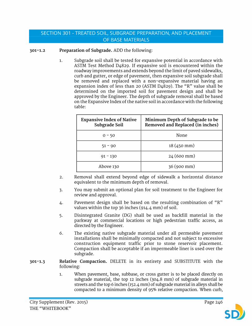
City Supplement (Rev. 2015) Page 246 THE “WHITEBOOK”
SECTION 301 - TREATED SOIL, SUBGRADE PREPARATION, AND PLACEMENT OF BASE MATERIALS
301-1.2 Preparation of Subgrade. ADD the following:
1. Subgrade soil shall be tested for expansive potential in accordance with ASTM Test Method D4829. If expansive soil is encountered within the roadway improvements and extends beyond the limit of paved sidewalks, curb and gutter, or edge of pavement, then expansive soil subgrade shall be removed and replaced with a non-expansive material having an expansion index of less than 20 (ASTM D4829). The “R” value shall be determined on the imported soil for pavement design and shall be approved by the Engineer. The depth of subgrade removal shall be based on the Expansive Index of the native soil in accordance with the following table:
Expansive Index of Native Subgrade Soil
Minimum Depth of Subgrade to be Removed and Replaced (in inches)
0 - 50 None
51 - 90 18 (450 mm)
91 - 130 24 (600 mm)
Above 130 36 (900 mm)
2. Removal shall extend beyond edge of sidewalk a horizontal distance equivalent to the minimum depth of removal.
3. You may submit an optional plan for soil treatment to the Engineer for review and approval.
4. Pavement design shall be based on the resulting combination of “R” values within the top 36 inches (914.4 mm) of soil.
5. Disintegrated Granite (DG) shall be used as backfill material in the parkway at commercial locations or high pedestrian traffic access, as directed by the Engineer.
6. The existing native subgrade material under all permeable pavement installations shall be minimally compacted and not subject to excessive construction equipment traffic prior to stone reservoir placement. Compaction shall be acceptable if an impermeable liner is used over the subgrade.
301-1.3 Relative Compaction. DELETE in its entirety and SUBSTITUTE with the following:
1. When pavement, base, subbase, or cross gutter is to be placed directly on subgrade material, the top 12 inches (304.8 mm) of subgrade material in streets and the top 6 inches (152.4 mm) of subgrade material in alleys shall be compacted to a minimum density of 95% relative compaction. When curb,

City Supplement (Rev. 2015) Page 247 THE “WHITEBOOK”
gutter, driveways, or sidewalks are to be placed on the subgrade material, the top 6 inches (152.4 mm) of such subgrade material shall be compacted to a relative compaction of 90%.
2. When permeable pavements are to be placed on the subgrade material, the top 12 inches (304.8 mm) of such subgrade material shall be compacted to a relative compaction of 95% in road travel lanes and 90% in all other applications (curb, gutter, alley, driveway, sidewalk, parking lane, and parking lot) unless otherwise specified.
3. After compaction and trimming, the subgrade shall be firm, hard, and unyielding.
4. The subgrade shall be tested with a load truck possessing a 10 ton capacity load or greater. The tire contact area shall have a load capacity of 75 pounds or more per square inch (≥ 75 psi) (517 kPa). The subgrade shall support this load without perceptible indentation or movement. The base, surfacing, or pavement shall not be scheduled for construction until the subgrade has been tested as described above and approved by the Engineer.
301-1.6 Adjustment of Manhole and Gate Valve Frames and Covers to Grade. DELETE in its entirety and SUBSTITUTE with the following:
1. Castings, pre-fabricated risers, and frames or covers of existing City manholes or gate valves shall be adjusted to conform to the new grade.
2. Sewer and storm drain manhole covers shall be raised by installing pre-fabricated risers manufactured in 1 inch (25.4 mm) increments. In some locations, due to the existing condition of the manhole, the Engineer may require digging up and repairing the existing manhole according to the following criteria:
a) The pavement shall be cut to a width of no less than 8 inches (203.2 mm) or more than 12 inches (304.8 mm) and a depth of no less than 6 inches (152.4 mm) around the circumference of the manhole frame. The outside cut shall be as neat and clean as possible to insure a smooth joint between asphalt and concrete collar.
b) Once the frame has been broken loose and the debris is cleared away, the frame shall be shimmed to match the new grade. Only broken brick shall be used for shimming as it will remain a permanent part of the frame base. The space shall then be grouted to ensure total and complete support of the manhole frame.
c) The concrete collar shall then be poured and finished to ensure a level and smooth connection between the asphalt pavement and manhole. Manhole frames shall be set in Class "C" mortar.
3. Gate valve caps, casings, and leveling shall be done after resurfacing. Measurements shall be made from the top of the new grade to the top of

City Supplement (Rev. 2015) Page 248 THE “WHITEBOOK”
the gate cap to determine the length requirement for the extension of the valve riser casing. This extension shall be cut from 8 inches (203.2 mm) O.D. by 1/8 inch (3.2 mm) steel casing only. The gate valve cap shall be removed. The extension shall be placed on the existing riser casing. The gate valve cap shall be replaced and checked for assurance as to height and levelness. The extension shall be circumferentially welded to the old casing.
4. In the event that an old style casing of a different size is found, the following procedures shall be followed:
a) Pavement around the gate valves shall be cut to a width within 6 inches to 8 inches (152.4 mm to 203.2 mm) and to a minimum depth of 8 inches (203.2 mm) around the circumference of the valve casing. The new casing shall then be placed around or inside the old casing.
b) A concrete collar shall be poured and finished to ensure a level and smooth connection between the asphalt and gate valve cover. 8 inch (203.2 mm) gate caps will be furnished by the City to replace old and oddly sized caps.
c) Gate valve caps and sewer manholes covered by resurfacing will be located and marked out by City Forces and shall be raised by you in the same manner described in these specifications.
d) Except for those areas which have been identified for cold milling in accordance with 302-1, “Cold Milling of Existing Pavement”, you shall be responsible for locating all metal objects in the area that shall be milled.
301-1.7 Payment. DELETE in its entirety and SUBSTITUTE with the following:
1. The payment for preparing a subgrade will be considered as included in the item of Work for which the subgrade is prepared.
2. When used, DG shall be included in the Bid item for “Miscellaneous Hardscape Remove and Replace with Topsoil” in accordance with 300-1.4, “Payment” unless a separate Bid item has been provided.
3. The payment for grading operations in areas designated as “grade only” shall be considered as included in the item of Work for excavation or fill.
4. The payment for adjusting existing manhole frames and covers to grade shall be included in the Bid item for “Adjust Existing Manhole Frame and Cover to Grade”.
5. The payment for adjusting existing gate valve frames and covers to grade shall be included in the Bid item for “Adjust Existing Gate Valve Frame and Cover to Grade”.
6. If no provision for manhole adjustments or reconstruction is made, payment shall be considered included under other items of Work and no additional payment will be made.
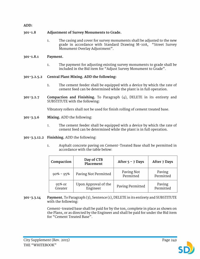
City Supplement (Rev. 2015) Page 249 THE “WHITEBOOK”
ADD:
301-1.8 Adjustment of Survey Monuments to Grade.
1. The casing and cover for survey monuments shall be adjusted to the new grade in accordance with Standard Drawing M-10A, “Street Survey Monument Overlay Adjustment”.
301-1.8.1 Payment.
1. The payment for adjusting existing survey monuments to grade shall be included in the Bid item for “Adjust Survey Monument to Grade”.
301-3.2.5.2 Central Plant Mixing. ADD the following:
1. The cement feeder shall be equipped with a device by which the rate of cement feed can be determined while the plant is in full operation.
301-3.2.7 Compaction and Finishing. To Paragraph (4), DELETE in its entirety and SUBSTITUTE with the following:
Vibratory rollers shall not be used for finish rolling of cement treated base.
301-3.3.6 Mixing. ADD the following:
1. The cement feeder shall be equipped with a device by which the rate of cement feed can be determined while the plant is in full operation.
301-3.3.12.2 Finishing. ADD the following:
1. Asphalt concrete paving on Cement-Treated Base shall be permitted in accordance with the table below:
Compaction Day of CTB Placement After 5 - 7 Days After 7 Days
90% - 95% Paving Not Permitted Paving Not Permitted
Paving Permitted
95% or Greater
Upon Approval of the Engineer Paving Permitted Paving
Permitted
301-3.3.14 Payment. To Paragraph (3), Sentence (1), DELETE in its entirety and SUBSTITUTE with the following:
Cement-treated base shall be paid for by the ton, complete in place as shown on the Plans, or as directed by the Engineer and shall be paid for under the Bid item for “Cement Treated Base”.

City Supplement (Rev. 2015) Page 250 THE “WHITEBOOK”
ADD:
301-6 PERMEABLE PAVEMENT STRUCTURAL BASE AND SUBBASE.
301-6.1 General.
1. Permeable pavement structural base shall be constructed of material conforming to Table 200-1.2.1 (A) AASHTO No. 57.
2. The permeable pavement structural subbase shall be constructed of material conforming to Table 200-1.2.1 (A) ASTM No. 2.
3. Rounded river material shall not be used for vehicular applications.
301-6.2 Spreading.
1. Imported aggregate bases/subbases shall be delivered to the roadbed as uniform mixtures and each layer shall be spread in one operation. Segregation shall be avoided and the base/subbase shall be free from pockets of coarse or fine material.
2. Aggregate bases/subbases shall be deposited on the roadbed at a uniform quantity per linear foot (meter) which quantity will provide the required compacted thickness within the tolerances specified herein without resorting to spotting, picking up, or otherwise shifting the aggregate base/subbase material. At the time the aggregate is spread, it shall have a moisture content sufficient to obtain the required compaction. Such moisture shall be uniformly distributed throughout the material.
3. The base thickness shall be installed to a minimum of 4 inches (100 mm) and a maximum of 6 inches (150 mm). The layer may be spread and compacted in 1 layer.
4. The subbase thickness shall be installed to a minimum of 6 inches (150 mm). Where the required thickness is more than 6 inches (150 mm) the subbase material shall be spread and compacted in 2 or more layers of approximately equal thickness and the maximum compacted thickness of any one layer shall not exceed 6 inches (150 mm). Each layer shall be spread and compacted in a similar manner.
301-6.3 Compacting.
1. Each lift shall be compacted with a minimum 10 ton roller to be firm and unyielding. A minimum of 2 passes with a vibratory roller and then 2 passes with a static roller should be performed until there is no visible movement of the base/subbase. The aggregate shall not be crushed.
301-6.4 Measurement and Payment.
1. Quantities of structural base/subbase will be measured by ton and shall be paid for under the Bid item for “Permeable Pavement Structural Base And Subbase”. The volumetric quantities of base/subbase material shall be those compacted in place within the limits of the dimensions shown on the Plans.
2. The weight of material to be paid for shall be determined by deducting (from the weight of material delivered to the Work) the weight of water in the material (at the time of weighing) in excess of 1% more than the optimum

City Supplement (Rev. 2015) Page 251 THE “WHITEBOOK”
moisture content. No payment shall be made for the weight of water deducted as provided in this subsection.
ADD:
301-7 PERMEABLE INTERLOCKING CONCRETE PAVERS BEDDING.
301-7.1 General.
1. Permeable interlocking concrete pavers bedding layer shall be constructed of material conforming to Table 200-1.2.1 (A) ASTM No. 8, ASTM No. 89, or ASTM No. 9 as directed by the Plans.
301-7.2 Spreading.
1. Imported aggregate bedding shall be delivered to the roadbed as uniform mixtures and each layer shall be spread in 1 operation. Segregation shall be avoided and the bedding shall be free from pockets of coarse or fine material.
2. Aggregate bedding shall be deposited on the roadbed at a uniform quantity per linear foot (meter) which quantity will provide the required compacted thickness within the tolerances specified herein without resorting to spotting, picking up, or otherwise shifting the aggregate bedding material. At the time the aggregate is spread, it shall have a moisture content sufficient to obtain the required compaction. Such moisture shall be uniformly distributed throughout the material.
3. The bedding thickness shall be installed at 2 inches (50.8 mm). The layer may be spread and compacted in 1 layer.
4. The surface tolerance of the screeded bedding material is ± 3/8 inches over 10 feet (± 9.5 mm over 3 m).
301-7.3 Measurement and Payment.
1. Quantities of structural bedding shall be measured by the square yard (square meter) or cubic yard (cubic meter) in place as shown on the Plan or as directed by the Engineer and shall be paid for under the Bid item for “Permeable Interlocking Concrete Pavers Bedding”. The volumetric quantities of bedding material shall be those compacted in place within the limits of the dimensions shown on the Plans.
2. The weight of material to be paid for shall be determined by deducting (from the weight of material delivered to the Work) the weight of water in the material (at the time of weighing) in excess of 1% more than the optimum moisture content. No payment shall be made for the weight of water deducted as provided in this subsection.

City Supplement (Rev. 2015) Page 252 THE “WHITEBOOK”
ADD:
301-8 GRADED AGGREGATE CHOKER STONE.
301-8.1 General
1. Graded aggregate choker stone is installed to separate the bioretention soil media specified in the Special Provisions from the drainage rock reservoir layer to ensure that no migration of sand or other fines occurs. The graded aggregate choker stone consists of two layers of media increasing in size. The top layer of the graded aggregate choker stone shall be constructed of sand material conforming to 200-1.5.7, “Sand for Graded Aggregate Choker Stone”. The bottom layer of the graded aggregate choker stone shall be constructed of aggregate material conforming to Table 200-1.2.1 (A) ASTM No. 8.
301-8.2 Spreading.
1. Imported graded aggregate choker stone shall be delivered to the roadbed as uniform mixtures and each layer shall be spread in 1 operation. Segregation within each aggregate layer shall be avoided and the layers shall be free from pockets of coarse or fine material.
2. Aggregate shall be deposited on the drainage stone at a uniform quantity per linear foot (meter) which quantity will provide the required compacted thickness within the tolerances specified herein without resorting to spotting, picking up, or otherwise shifting the aggregate material.
3. The bottom layer of the graded aggregate choking stone (ASTM No.8) shall be installed to a thickness of 2 inches (50.8 mm). The layer shall be spread in 1 layer. The top layer of the graded aggregate choking stone (ASTM C33) shall be installed to a thickness of 2 inches (50.8 mm).
301-8.3 Compacting.
1. Rolling shall always commence along the edge of the area to be compacted and the roller shall gradually advance toward the center of the area to be compacted. Vibratory compaction shall not be permitted.
2. The minimum relative compaction of the aggregate choker stone shall be 90%.
301-8.4 Measurement and Payment.
1. Quantities of graded aggregate choker stone shall be measured by square yard (square meter) or cubic yard (cubic meter) as shown on the Plan or as directed by the Engineer and shall be paid for under the Bid item for “Graded Aggregate Choker Stone”. The volumetric quantities of graded aggregate choker stone material shall be those placed within the limits of the dimensions shown on the Plans.
2. The weight of material to be paid for shall be determined by deducting (from the weight of material delivered to the Work) the weight of water in the material (at the time of weighing) in excess of 1% more than the optimum moisture content. No payment shall be made for the weight of water deducted as provided in this subsection.

City Supplement (Rev. 2015) Page 253 THE “WHITEBOOK”
SECTION 302 - ROADWAY SURFACING
302-1.1 General. ADD the following:
1. Excessive asphalt concrete pavement adjacent to Type “G” and “H” curb and gutter lines and concrete cross gutters shall be milled in accordance with the City of San Diego Standard Drawing SDG-107 for “Trench Resurfacing for Asphalt Concrete Surfaced Streets” or as shown on the Plans.
2. Cross gutters shall be cold milled 1 inch ± ¼ inch (25.4 mm ± 6.35 mm) within 24 hours or less of the time the resurfacing is placed. In areas where the curb height has been diminished by multiple overlays, the milling depth shall equal the proposed overlay thickness. Cross gutters shall be cold milled a minimum of 1.5 inches (38.1 mm) within 5 Days of the time the resurfacing is placed.
3. Milled widths of pavement shall be continuous except for intersections at cross streets where the milling shall be carried around corners and daylighting at the point of curb return. The header cuts shall daylight at the point of curb return or as directed by the Engineer.
4. Milled widths of pavement shall be continuous except for intersection at cross streets where header cuts shall daylight at the point of curb return or as directed by the engineer. Header cuts shall be 12 feet (3.7 m) in width at intersections, cross gutters, and paving limits or as directed by the Engineer.
5. The City acknowledges that certain unidentified utility facilities (buried metal objects such as magnetic traffic pads, sewer and storm drain manhole covers, water valve covers, survey monuments, and etc.) have been inadvertently paved over on some streets in past projects. These facilities may not be readily apparent from a visual inspection of the project or from an examination of As-Built records. You shall be responsible for locating and protecting these facilities in accordance with 5-1, “Utilities”.
6. You shall make reasonable efforts to locate the buried metal objects. You shall examine any available As-Built records, properly notify “UNDERGROUND SERVICE ALERT” (USA), and request that all utility lines, covers, and facilities within 6 inches (152.4 mm) of the surface be identified and marked. If requested by the Engineer, provide documentation that this service was completed.
7. You shall sweep all street locations with a metal detector ahead of the milling operation. Suspected buried metal objects shall be identified by a painted cross within an outlined area in a manner allowing the milling operation to see the questionable area and take corrective action. Any damage incurred by the milling machine striking a buried metal object within a 3 foot (0.9 m) radius of such a marking shall be at your expense.
8. At each street location screened with a metal detector, you shall note that the street has been checked by painting a checkmark at a location that is approved by the Engineer. This mark should be visible to the Engineer and the milling operator but shall not be placed to divert or confuse public traffic.

City Supplement (Rev. 2015) Page 254 THE “WHITEBOOK”
9. The Engineer shall be notified a minimum of 24 hours in advance of any street that is to be swept for buried metal objects. Proper traffic control shall be erected and maintained for all metal detection operations. If, after any given street has been checked with the metal detector, the milling operation hits more than 2 buried objects, then you shall revise their methods and re-check street locations at your expense.
10. You shall cold mill the full width of existing streets to the depths specified in the Contract Documents or as directed by the Engineer. Cold milled full width locations shall be paved within 3 Days.
11. If approved by the Engineer, equipment other than milling machines may be utilized to achieve the removal of distressed asphalt pavement.
12. Existing traffic striping and thermoplastic markings located within the limits of the area to receive asphalt overlay or slurry seal shall be removed a maximum of 10 Days prior to the application of asphalt overlay or slurry seal by wet sandblasting or other approved methods. Dry sandblasting may be used in selected areas only with the permission of the Engineer and with approval of the air pollution control authority having jurisdiction over the area in which the Work will be performed. Temporary striping for thermoplastic markings and temporary tabs shall be applied to any pavement exceeding the 10 Day requirement.
ADD:
302-1.1.1 Removal of Humps and Pavement Irregularities.
1. Removal of humps and pavement irregularities include areas 1 inch (25.4 mm) or more above the finish grade of the existing pavement surface as marked in the street or as directed by the Engineer. The removal of the hump or irregularity may be done either by milling or other means. The required hot mix asphalt concrete patching shall be C2 PG 64-10 in accordance with 203-6, “Asphalt Concrete”.
2. At the end of each Working Day, you shall submit to the Engineer an itemized list of the areas where the removal of humps has been completed. The list shall include the location of the Work and the exact length in linear feet.
302-1.6 Cold Milling of Composite Pavements. ADD the following:
1. You shall account for concrete trench caps up to 12 inches (304.8 mm) of concrete with ¼ inch (6.4 mm) of asphalt.
2. Composite Pavements not shown on the plans shall be measured in accordance with 302-1.11, “Measurement”.
ADD:
302-1.6.1 Cold Milling of Asphalt Concrete with Pavement Fabric Material.
1. Pavement fabric material includes fabrics which conform to Table 213-4.1. Fiberglass or fiberglass composite fabrics conforming to Table 213-4.1 are not included. The area of pavement containing pavement fabric

City Supplement (Rev. 2015) Page 255 THE “WHITEBOOK”
material shall be measured in accordance with 302-1.11, “Measurement”.
302-1.9 Traffic Signal Loop Detectors. ADD the following:
1. The Engineer will determine which traffic detector loops and/or other detection systems shall be replaced unless specified otherwise in the Contract Documents.
2. Traffic detector loops shall be reinstalled prior to the resurfacing of the related street within 15 Days from completion of all preparatory Work which includes milling, cutting, and grinding. You shall contact the City of San Diego’s Street Division in Traffic Signal Maintenance per the table below to request the loop layout and/or for other detection systems within pavement.
North of Interstate 8 619-527-8052
South of Interstate 8 619-527-8053
3. Traffic Signal Maintenance shall lay out locations and size of new loops and will inspect the installation. You shall be responsible for making field connections. You shall obtain prior approval from the Street Division for each traffic loop stub out replaced.
4. Traffic detector loops installed either in the new street surface or in the original street surface after grinding or repairs shall be Caltrans type “E” loops as described in Caltrans Standard Plan ES-5B. The front loop at the stop line shall have 4 turns instead of the 3 that is required by Caltrans. Asphaltic emulsion loop sealants shall not be used when installing traffic loops on the street surface.
302-1.10 Pavement Transitions. ADD the following:
1. Where transverse joints are milled in the pavement, no drop-off shall remain between the existing pavement and the milled area when the pavement is opened to public traffic. If asphalt concrete has not been placed to the level of the existing pavement before the pavement is to be opened to public traffic, a temporary asphalt concrete taper shall be constructed. Asphalt concrete for temporary tapers shall be placed to the level of the existing pavement and tapered on a slope of 15: l or flatter to the level of the planed area. Asphalt concrete for temporary tapers shall be commercial quality and may be spread and compacted by any method that will produce a smooth riding surface. Temporary asphalt concrete tapers shall be completely removed, including the removal of all loose material from the underlying surface, before placing the permanent surface.

City Supplement (Rev. 2015) Page 256 THE “WHITEBOOK”
302-1.11 Measurement. ADD the following:
1. At the end of each day, you shall submit to the Engineer an itemized list of the areas where removal of humps was completed. The list shall include the location of the Work and the length in linear feet. Measurement for the removal of street humps and pavement irregularities prior to the placement of asphalt concrete shall be of actual areas and depths authorized by the Engineer and shall be calculated in lineal feet based on a 1 foot by 6 foot (0.3 m by 1.8 m) drum width.
302-1.12 Payment. ADD the following:
1. The payment for the replacement of traffic detector loops and appurtenances shall be included in the Bid item for each “Traffic Signal Loop and Appurtenance Replacement” as shown in the Bid.
2. The payment for the removal of humps and other pavement irregularities shall be included in the linear foot Bid item for “Removal of Humps and Pavement Irregularities”. No additional payment shall be made for incidental asphalt patching required after hump removal.
3. The payment for cold milling shall be included in the Contract Price unless Bid items, as applicable, have been provided as follows:
BID DESCRIPTION UNIT
Cold Mill AC Pavement (0 Inch – 1½ Inch) SF
Cold Mill AC Pavement (> 1½ Inch – 3 Inch) SF
Cold Mill AC Pavement (> 3 Inch) SF
Cold Mill Header Cuts LF
4. In the event that concrete in excess of the total area milled in a particular street segment (block) is encountered, payment shall be made at the Bid unit price as specified in the table below. Prior to paving over the milled areas, you shall notify the Engineer that the incidental amount has been exceeded.
EXCESS IN PERCENTAGE
OF TOTAL AREA
TYPE OF CONCRETE TO
BE MILLED BID DESCRIPTION UNIT
5% Composite Pavements
Cold Milling of Additional Composite
Pavements SF
5% Asphalt Concrete
with Pavement Fabric Material
Cold Milling of Additional Asphalt
Concrete with Pavement Fabric Material
SF

City Supplement (Rev. 2015) Page 257 THE “WHITEBOOK”
302-2.5 Temporary Traffic Control. To Sentence (1), REVISE “In addition to the requirements of 601” to “In addition to the requirements of Part 6”.
To sub-items “d”, “e”, and “f”, REVISE as follows:
OLD TITLE REVISED TITLE
C6 W8-7
W6 G20-5aP with R2-1
302-3 Not Used. DELETE in its entirety and SUBSTITUTE with the following:
302-3 PREPARATORY REPAIR WORK.
1. Prior to the placement of asphalt concrete or the application of slurry, you shall complete all necessary preparation and repair Work to the road segment as specified in the Special Provisions.
2. Unless otherwise specified, preparatory Work shall include tree trimming, weed spray, weed abatement, crack sealing, asphalt repair, mill and pave, hump removal, miscellaneous asphalt patching, removal of raised pavement markers, and removal of pavement markings.
3. You shall repair areas of distressed asphalt concrete pavement by milling or removing damaged areas of pavement to a minimum depth of 2 inches (50.8 mm) for residential streets and a minimum depth of 3 inches (76.2 mm) for all others to expose firm and unyielding pavement.
4. You shall prepare subgrade as needed and install a minimum of 2 inches (50.8 mm) for residential streets and a minimum of 3 inches (76.2 mm) for all other streets of compacted asphalt concrete pavement over compacted native material as directed by the Engineer.
5. If the base material is exposed in order to achieve the minimum specified depth, the material shall be compacted to 95% relative compaction (dig out). Compaction tests shall be made to ensure compliance with the specifications.
6. The Engineer shall determine when and where the test shall occur. The City will pay for the soils testing required by the Engineer which meets the required compaction. You shall reimburse the City for the cost of retesting failing compaction tests. If additional base material is required, you shall use Class 2 Aggregate Base in accordance with 200-2.2, “Crushed Aggregate Base”.
7. Recycled base material shall conform to crushed miscellaneous base material in accordance with 200-2.4, “Crushed Miscellaneous Base”.
8. Prior to replacing asphalt, the area shall be cleaned by removing all loose and damaged material, moisture, dirt, and other foreign matter and shall be tack coated in accordance with 302-5.4, “Tack Coat”.

City Supplement (Rev. 2015) Page 258 THE “WHITEBOOK”
9. You shall install new asphalt within the repair area or for patches in accordance with 302-5, “Asphalt Concrete Pavement”. Asphalt concrete shall be C2-PG 64-10 in compliance with 203-6, “Asphalt Concrete”.
10. No preparatory asphalt Work shall be done when the atmospheric temperature is below 50° F (10° C) or during unsuitable weather.
11. Following the asphalt placement, you shall roll the entire area of new asphalt in both directions at least twice. The finished patch shall be level and smooth in compliance with 302-5.6.2, “Density and Smoothness”. After placement and compaction of the asphalt patch, you shall seal all finished edges with a 4 inch (101.6 mm) wide continuous band of SS-1H.
12. The minimum dimensions for each individual repair shall be 4 feet by 4 feet (1.2 m by 1.2 m) and shall be subject to the following conditions:
a) If the base material is exposed to achieve the required minimum removal thickness, the base material shall be prepared conforming to 301-1, “SUBGRADE PREPARATION”.
b) When additional base material is required, then you shall use Class 2 Aggregate Base in accordance with 200-2.2, “Crushed Aggregate Base”. Recycled base material shall conform to crushed miscellaneous aggregate base material in accordance with 200-2.4, “Crushed Miscellaneous Base”.
c) You may use grinding as a method for removal of deteriorated pavement when the areas indicated for removal are large enough (a minimum of the machine drum width) and when approved by the Engineer.
d) For both scheduled and unscheduled base repairs, failed areas may be removed by milling or by excavation provided that the edges are cut cleanly with a saw. The areas shall be cleaned and tack coated in accordance with 302-5.4, “Tack Coat” before replacing the asphalt. The areas for scheduled repairs have been marked on the street.
e) Base Repairs with RAC. Areas where failed paving is removed either by cold milling or by excavation shall be restored to existing pavement grade with ¾ inch (19.1 mm) RAC at 8 inch (203.2 mm) depth unless otherwise directed by the Engineer. These areas have been marked on the street as “DO”. The asphalt concrete shall be B3-PG 64-10 as specified in 203-6, “Asphalt Concrete”. Preliminary quantities are identified in the Contract Appendix but may need to be increased and approved by the Engineer at the time of construction. Base repairs shall not exceed 15% RAP in content.
f) Unscheduled Base Repair with RAC. If paving operations cause damage outside of your control and require additional base repair, the areas shall be removed either by cold milling or by excavation and shall be restored to existing pavement grade with ¾ inch

City Supplement (Rev. 2015) Page 259 THE “WHITEBOOK”
(19.1 mm) RAC at 8 inch (203.2 mm) depth unless otherwise directed by the Engineer. The asphalt concrete shall be B3-PG 64-10 as specified in 203-6, “Asphalt Concrete”. Unscheduled base repairs shall not exceed 15% RAP.
g) A base repair is considered unscheduled when it is not identified on the pavement with a “DO” or when you are directed by the Engineer to perform a base repair for the proper placement of an asphalt overlay.
302-3.1 Asphalt Patching.
1. Asphalt patching shall consist of patching potholes, gutter-line erosions, and other low spots in the pavement that are deeper than ½ inch (12.7 mm) in accordance with 302-5.6.2, “Density and Smoothness”.
2. The areas requiring patching have been identified in the Contract Documents, marked on the streets, or as directed by the Engineer. You shall identify any new areas that may require patching prior to slurry Work to ensure the smoothness and quality of the finished product.
3. You shall identify and repair any areas that may require patching prior to the placement of slurry seal for a smooth and finished product.
4. Asphalt overlay shall not be applied over deteriorating pavement. Preparatory asphalt Work shall be completed and approved by the Engineer before proceeding with asphalt overlay.
5. You shall remove distressed asphalt pavement either by saw cutting or milling to expose firm and unyielding pavement, prepare subgrade (as needed), and install compacted asphalt concrete pavement over compacted native material as directed by the Engineer.
6. Prior to replacing asphalt, the area shall be cleaned and tack coated in accordance with 302-5.4, “Tack Coat”.
7. Following the asphalt placement, you shall roll the entire patch in both directions and shall cover the patch at least twice.
8. After placement and compaction of the asphalt patch, you shall seal all finished edges with a 4 inch (101.6 mm) wide continuous band of SS-1H.
9. Base repairs shall not exceed 15% RAP in content.
302-3.2 Payment.
1. The payment for the replacement of existing pavement when required shall be included in the Contract Unit Price for “Asphalt Pavement Repair” for the total area replaced and no additional payment shall be made regardless of the number and size of replacements completed. No payment shall be made for areas of over-excavation or outside trench

City Supplement (Rev. 2015) Page 260 THE “WHITEBOOK”
areas in utility Works unless previously approved by the Engineer. No payment for pavement replacement will be made when the damage is due to your failure to protect existing improvements. You shall reimburse the City for the cost of retesting all failing compaction tests.
2. The areas and quantities shown on the road segments and in the appendices are given only for your aid in planning the Work and preparing Bids. The Engineer will designate the limits to be removed and these designated areas shall be considered to take precedence over the area shown in an Appendix to the Contract Documents. The quantities shown in the appendices are based on a street assessment survey and may vary.
3. At the end of each day, you shall submit to the Engineer an itemized list of the asphalt pavement repair Work completed. The list shall include the location of the Work and the exact square footage of the repair.
4. The payment for preparatory repair Work and tack coating shall be paid at the Contract Unit Price for “Asphalt Pavement Repair”.
5. The payment for milling shall be included in the Bid item for “Asphalt Pavement Repair” unless Bid items for asphalt milling Work has been provided.
6. The payment for miscellaneous asphalt patching shall be included in the Contract Unit Price for the slurry Work and no additional payment shall be made, unless a Bid item for “Miscellaneous Asphalt Patching” has been provided.
7. The payment for subgrade preparation and material shall be included in the Contract Unit Price for “Subgrade Imported Backfill”.
302-4.1 General. ADD the following:
1. Type II REAS or RPMS shall be applied to all streets unless otherwise specified in the Contract Documents or as directed by the Engineer.
2. Due to construction conflicts or community needs that may arise, the City reserves the right to add, delete, or substitute similar road segments to those listed in the contract documents. The City reserves the right to select exact locations to be substituted. If substantial changes to the contract Bid quantities occur, this may allow individual Bid prices to be renegotiated in accordance with 3-2, “CHANGES INITIATED BY THE AGENCY”.
302-4.2 Aggregate Stockpile. ADD the following:
1. Aggregate may be stockpiled on public property sites if approved by the Engineer.
2. You shall make all arrangements for and shall assume full responsibility of the rental, preparation, and maintenance of private property at your discretion and shall obtain the appropriate permits for its usage.

City Supplement (Rev. 2015) Page 261 THE “WHITEBOOK”
3. You shall clean public and/or private property in a manner satisfactory to the City and the property owner. Precautions shall be taken to ensure that stockpiles do not become contaminated with oversized rock, clay, silt, or excessive amounts of moisture. Segregation of the aggregate shall not be permitted. Aggregate samples shall be taken from field stockpile locations prior to any addition of mineral fillers such as cement or lime to determine the sand equivalent value in accordance with 203-5.4.2, “Materials”. The addition of mineral fillers such as cement, lime, or sulphates may be added during the application of the slurry mixture to the City streets.
4. You shall provide suitable storage facilities for the asphalt emulsion. Suitable heat shall be provided as necessary.
5. Immediately prior to slurry sealing operations, all utilities covers and monuments shall be covered by heavy plastic material or other means approved by the Engineer. Covers and voids around frames shall be cleaned of slurry material by the end of the same Work day. If the utility covers are not cleaned by the following Day, no additional slurry seal shall be placed until the covers are cleaned.
6. Prior to the application of slurry to any road segment, you shall complete all necessary preparatory repair Work in accordance with 302-3, “Preparatory Repair Work”.
7. No preparatory asphalt Work shall be done when the atmospheric temperature is below 50° F (10° C) or during inclement weather.
8. Decorative and tile walkway crossings shall be protected from slurry seal operations.
9. Care shall be exercised to ensure the maximum rate of application with no excess emulsion and leaving no unsightly appearance. You shall be responsible for the removal of all excess emulsion spread beyond street limits, on driveways, on sidewalks, and etc.
10. No less than 5 Days or more than 30 Days following the placement of slurry seal, the street shall be re-swept to remove the gravel rebound from vehicular traffic.
302-4.3.1 General. ADD the following:
1. All metering devices shall be calibrated and certified within the past 12 months. Calibration certificates shall be submitted to the Engineer.
ADD:
302-4.7.1.1 Seasonal Work and Separate Agreement.
1. REAS shall not be placed during the months of November, December, January, February, and March. If the Work performed in accordance with these specifications progresses such that the slurry sealing Work would occur during the months specified above, you and the City shall enter

City Supplement (Rev. 2015) Page 262 THE “WHITEBOOK”
into a separate agreement for the performance of the slurry sealing Work during an alternate time period. The separate agreement shall be in the form attached to the Contract documents as an Appendix.
2. Execution of a Seasonal Work and Separate Agreement between you and the City shall constitute the satisfactory completion of the slurry sealing Work for the purpose of filing the Notice of Completion for the Contract. Prior to the execution of the Seasonal Work and Separate Agreement between you and the City, you shall provide the City with the following:
a) A faithful performance bond in the amount of 100% of your Bid item for 302-4.6, “Emulsion-Aggregate Slurry”.
b) A certificate of insurance demonstrating in a manner satisfactory to the City that you have the insurance coverage required by the separate agreement.
3. If you and the City enter into a separate agreement for the slurry sealing Work, you shall be paid in accordance with the terms outlined in the Seasonal Work and Separate Agreement.
ADD:
302-4.8.1 Slurry Consistency (Slurry Slump Test).
1. Consistency of the mixed slurry shall be measured using a machined-surface brass cone (per ISSA test 106/ASTM C-128).
2. The cone shall be a hollow 0.03 inch (0.8 mm) minimum metal frustrum, 3 inches (76.2 mm) high, with 1.6 inches (40.6 mm) top inside diameter, and 3.6 inches (91.4 mm) inside base diameter. The flow scale shall consist of 7 concentric circles in 0.4 inch (10.2 mm) increasing radii from the circle formed by the outside larger end of the slump cone. The material on which the 7 concentric rings appear shall be 8½ inch by 11 inch (215.9 mm x 279.4 mm) Xerox paper, "Simpson # 7 ID 13351 10 M" or approved equal.
3. The test shall consist of sampling the mixed slurry then immediately pouring the sample into the top of the cone. Strike the slurry off even with the top of the cone and then raise the cone immediately. The flow shall be measured at 4 points 194° F (90° C) apart and then averaged. The average shall be between 0.8 inch and 1.2 inches (20.3 mm and 30.5 mm). If the slurry mix is not within these specifications, the water content of the slurry shall immediately be corrected to meet these specifications.
302-4.11.1.1 General. ADD the following:
1. If the results of the aggregate grading, the sand equivalent, or both do not meet the requirements specified, the slurry represented by such tests shall be removed and shall be reapplied with an acceptable batch.
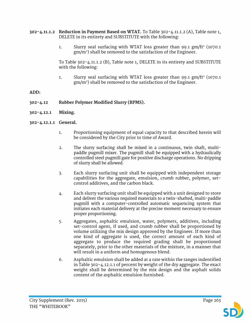
City Supplement (Rev. 2015) Page 263 THE “WHITEBOOK”
302-4.11.1.2 Reduction in Payment Based on WTAT. To Table 302-4.11.1.2 (A), Table note 1, DELETE in its entirety and SUBSTITUTE with the following:
1. Slurry seal surfacing with WTAT loss greater than 99.1 gm/ft2 (1070.1 gm/m2) shall be removed to the satisfaction of the Engineer.
To Table 302-4.11.1.2 (B), Table note 1, DELETE in its entirety and SUBSTITUTE with the following:
1. Slurry seal surfacing with WTAT loss greater than 99.1 gm/ft2 (1070.1 gm/m2) shall be removed to the satisfaction of the Engineer.
ADD:
302-4.12 Rubber Polymer Modified Slurry (RPMS).
302-4.12.1 Mixing.
302-4.12.1.1 General.
1. Proportioning equipment of equal capacity to that described herein will be considered by the City prior to time of Award.
2. The slurry surfacing shall be mixed in a continuous, twin shaft, multi-paddle pugmill mixer. The pugmill shall be equipped with a hydraulically controlled steel pugmill gate for positive discharge operations. No dripping of slurry shall be allowed.
3. Each slurry surfacing unit shall be equipped with independent storage capabilities for the aggregate, emulsion, crumb rubber, polymer, set-control additives, and the carbon black.
4. Each slurry surfacing unit shall be equipped with a unit designed to store and deliver the various required materials to a twin-shafted, multi-paddle pugmill with a computer-controlled automatic sequencing system that initiates each material delivery at the precise moment necessary to ensure proper proportioning.
5. Aggregates, asphaltic emulsion, water, polymers, additives, including set-control agent, if used, and crumb rubber shall be proportioned by volume utilizing the mix design approved by the Engineer. If more than one kind of aggregate is used, the correct amount of each kind of aggregate to produce the required grading shall be proportioned separately, prior to the other materials of the mixture, in a manner that will result in a uniform and homogenous blend.
6. Asphaltic emulsion shall be added at a rate within the ranges indentified in Table 302-4.12.1.1 of percent by weight of the dry aggregate. The exact weight shall be determined by the mix design and the asphalt solids content of the asphaltic emulsion furnished.
City Supplement (Rev. 2015) Page 264 THE “WHITEBOOK”
TABLE 302-4.12.1.1
Type of Aggregate Range
Type I 17% - 20%
Type II 14% - 17%
Type III 11% - 14%
7. The aggregate shall be proportioned by a belt feeder operated with an adjustable cutoff gate. The height of the gate opening shall be readily determinable. The emulsion shall be introduced into the mixer by a positive displacement pump. Water shall be introduced into the mixer through an adjustable multi-spray pugmill bar. Water volume shall be displayed by an electric digital meter registering in gallons delivered.
8. The aggregate belt feeder shall deliver aggregate to the pugmill mixed with such volumetric consistency that the deviation for any individual aggregate delivery rate check-run shall be within 2% of the mathematical average of 3 runs of at least 300 gallons (1135.6 L) each in duration.
9. The bitumen ratio (pounds of asphalt per 100 pounds (45.4 kg) of dry aggregates) shall not vary more than 1.5 pound (0.7 kg) of asphalt above or 0.6 pound (0.3 kg) asphalt below the amount designated by the mix design and approved by the Engineer.
10. The polymer additive and the carbon black shall be delivered to the mixer in the relative proportions required by means of a common shaft dual pump system. The polymer additive and the carbon black flow rates shall be independently adjustable by means of diaphragm valves and shall be sequenced through the computer controlled auto-sequencing system. The polymer additive and the carbon black shall be blended and mixed prior to their introduction into the pugmill. Introduction into the twin-shafted pugmill shall be done through an injection system which delivers the blended material to the apex of each mixing shaft immediately prior to the introduction of the asphalt emulsion. The polymer additive and the carbon black delivery system shall each be equipped with digital electronic flow metering devices that can read in gallons per minute.
11. The crumb rubber delivery system shall be equipped with an air suspension unit designed to prevent clumping or bridging of the rubber material. The air discharges shall be sequenced to avoid over-suspension of the rubber. The rubber shall be delivered to the pugmill by a hydraulically driven auger and shall be initiated through the computer controlled auto-sequencing system.
12. The emulsion shall be introduced into the mixer by a positive displacement pump. The emulsion storage shall be equipped with a device which will automatically shut down the power to the emulsion pump and aggregate belt feeder when the level of stored emulsion is lowered to within 2 inches (50.8 mm) of the suction line.
13. A temperature-indicating device shall be installed in the emulsion storage tank at the pump suction level.

City Supplement (Rev. 2015) Page 265 THE “WHITEBOOK”
14. The aggregate shall be proportioned using a belt feeder operated with an adjustable cutoff gate. The height of the gate opening shall be readily determinable.
15. The aggregate feeder shall be directly connected to the drive on the emulsion pump. The drive shaft of the aggregate feeder shall be equipped with an electronic digital belt. The belt delivering the aggregate to the pugmill shall be equipped with a device to monitor the depth of the aggregate being delivered to the pugmill. The device for monitoring the depth of aggregate shall automatically shut down the power to the aggregate belt feeder whenever the depth of aggregate is less than 70% of the target depth of flow. An additional device shall monitor movement of the aggregate belt by detecting revolutions of the belt feeder. The devices for monitoring no flow or belt movement shall automatically shut down the power to the aggregate belt when the aggregate belt movement is interrupted. To avoid shutdown caused by normal fluctuations in delivery rates, a delay of 3 seconds between sensing less than desirable storage levels of aggregate or emulsion shall be permitted.
16. Water delivery shall be adjusted through a diaphragm valve. Water flow rate shall be electronically displayed through a digital meter.
17. Set control additive flow rate shall be electronically displayed through a digital meter.
18. The mixer unit shall not be operated unless all electronic display and revolution counters are in good working condition and functioning and all metal guards are in place. All indicators required by these specifications shall be operational at all times.
19. You shall have 2 fully operational mixers and 1 standby mixer for use at the Project Site at all times for each working crew.
302-4.12.2 Application.
302-4.12.2.1 General.
1. The Work shall consist of mixing asphaltic emulsions, aggregates, set-control additives, specially produced and graded crumb rubbers, and watering and spreading the mixture on the pavement where shown marked out in the field, as specified in these special provisions, and as directed by the Engineer. Type II RPMS shall be applied to all streets unless otherwise specified in the proposed Work Appendix of the Contract or as directed by the Engineer.
2. RPMS application rates shall be as follows:
TYPE APPLICATION RATE1 (lb/yd2)
I 9
II 13.33
III 15 – 22
1. Based on dry aggregate weight.
City Supplement (Rev. 2015) Page 266 THE “WHITEBOOK”
302-4.12.2.2 Spreading.
1. Pre-wetting of streets shall not be required unless streets are subject to high temperatures and/or dust.
2. The complete mixture, after the addition of water and any set-control agent used, shall be such that the mixture:
a) Has proper workability.
b) Shall permit a traffic flow without the occurrence of bleeding separation or other distress at 78° F (25.6° C) and without pilot-car-assisted traffic on the slurry seal within one hour after placement.
c) Shall prevent the development of bleeding, excessive raveling, separation, and/or other distress within 7 Days after placing the rubberized asphalt surfacing.
3. The slurry mixture shall be spread by means of a controlled spreader box. The spreader box shall be capable of spreading the slurry to the width of the traffic lane and shall have strips of flexible rubber belting or similar material on each side of the spreader that shall be in contact with the pavement to positively prevent loss of slurry from the ends of the box. Spreader boxes shall be equipped with reversible motor-driven augers when placing slurry. Rear flexible strike-off blades (rubbers) shall make close contact with the pavement and shall be adjustable to the various crown shapes so as to apply a uniform surfacing coat. Flexible drags to be attached to the rear of the spreader box shall be provided as directed by the Engineer. Drags and rubbers shall be cleaned daily if problems with cleanliness and longitudinal scouring occur. The spreader box shall be clean and shall be free of all slurry and emulsion at the start of each Work shift.
302-4.12.3 Rolling.
1. Pneumatic rolling shall be required on all streets. Rolling shall commence as soon as the RPMS has set sufficiently to prevent any material from adhering to the tires. The RPMS surface shall be rolled 2 to 5 times or as directed by the Engineer. Pneumatic rollers shall be operated at a minimum tire pressure of 60 psi (413.7 kPa).
302-4.12.4 Measurement and Payment.
1. RPMS shall be paid based on the square footage of RPMS applied. The measurement of RPMS applied shall be calculated by dividing the weight obtained from Certified Weighmaster Certificates by the spread rate for the type specified. You shall present Weighmaster Certificates for the amount of unused material remaining at the completion of the Work at no cost to the City. The payment shall be determined by deducting the amount of the unused material from the total amount of material delivered.
2. The payment for RPMS shall be the total square footage used on the project calculated using the method described and shall be paid under the following Bid items:

City Supplement (Rev. 2015) Page 267 THE “WHITEBOOK”
BID DESCRIPTION UNIT
Rubber Polymer Modified Slurry (RPMS) Type I and Striping SF
Rubber Polymer Modified Slurry (RPMS) Type II and Striping SF
Rubber Polymer Modified Slurry (RPMS) Type III and Striping SF
The Bid items for RPMS shall include full compensation for the specified surface preparation not included in other Bid items and shall include the Work necessary to construct the RPMS as specified on the Plans. Sweeping, removals, furnishing the aggregate required for the mix design, and thermoplastic pavement markings and striping in accordance with 314-4.4.6, “Payment” shall also be included in this Bid item. The payment for the thermoplastic striping of Continental Crosswalks shall be paid under the separate Bid item for “Continental Crosswalks” in accordance with 314-4.4.6, “Payment”.
3. The payment for asphalt patching shall be included in the Bid item for the slurry seal Work unless a Bid item has been provided for “Asphalt Patching for Slurry Seal”.
302-5.2 Not Used. DELETE in its entirety and SUBSTITUTE with the following:
302-5.2 Pavement Restoration Adjacent to Trench.
1. The Work for pavement restoration adjacent to trench shall include the following:
a) The replacement of existing pavement adjacent to the proposed trench.
b) The replacement of existing pavement outside the trench limits that was previously broken or displaced.
2. Prior to the commencement of the Work, you shall meet with the Engineer and determine the limits of the pavement to be replaced. If you do not meet with the Engineer before removing the pavement, all replacement outside the limits of the proposed trench resurfacing shall be at your expense.
3. Existing pavement shall be removed in accordance with 300-1.3.2, “Requirements”. Prior to pavement restoration, existing subgrade shall be prepared in accordance with 301-1, “SUBGRADE PREPARATION”.
City Supplement (Rev. 2015) Page 268 THE “WHITEBOOK”
302-5.2.1 Measurement and Payment.
1. The payment for pavement restoration adjacent to trench shall be made on a square foot basis as shown in the Bid in accordance with 302-6.8, “Measurement and Payment”. Unless separate Bid item(s) have been provided, the following shall be included in the payment for “Pavement Restoration Adjacent to Trench”:
a) Saw-cutting existing edges.
b) Removal and disposal of existing pavement.
c) Subgrade preparation including imported backfill material. Imported subgrade material shall be included in the Bid item for “Subgrade Imported Backfill”.
d) Form Work.
e) Placement, curing, and protection of new pavement.
302-5.4 Tack Coat. ADD the following:
1. A ‘cold pavement joint’ shall be defined as asphalt concrete pavement which has cooled below the lower limits of the spreading temperature prescribed in 302-5.5, “Distribution and Spreading”.
302-5.5 Distribution and Spreading. ADD the following:
1. Resurfacing shall be continuous throughout all intersections between the limits of the Work segment, unless otherwise shown on the Plans or directed by the Engineer.
2. If the street intersection has no parallel concrete cross gutters, resurfacing shall extend to the prolongation of curb or property line as directed by the Engineer. Where asphalt cross gutters are to be surfaced, furnish and have available a straight-edge and level the asphalt cross gutters. The drainage flow of the cross gutter shall be maintained under the direction of the Engineer.
3. Asphalt concrete shall be hand-raked to remove coarse aggregate and feathered to allow the fine materials to cover the existing street surface adjacent to concrete gutters and concrete cross gutters. Streets that have had previous overlays shall be cold planed.
4. If the street intersection has parallel cross gutters, resurfacing shall extend only to the near edge of the concrete where it shall be feathered.
5. If the street has intersecting concrete cross gutters, the street shall not be resurfaced. Asphalt shall be feathered at both edges of the concrete.
6. In all cases, extreme care shall be taken to prevent blocking drainage.
7. You shall unplug roof drains plugged by paving operations and shall rake asphalt into or away from existing driveways to provide smooth access and proper drainage to the gutter of the resurfaced street.

City Supplement (Rev. 2015) Page 269 THE “WHITEBOOK”
8. Asphalt alley aprons abutting streets to be resurfaced shall be resurfaced to the property line.
9. Do not tack coat more surface than can be overlaid on the same day.
10. On streets with grades higher than 5%, the asphalt concrete laydown shall be placed uphill or as determined by the Engineer.
11. City owned manholes, valve caps, vaults, or monuments within the resurfacing area shall be exposed for identification.
12. You shall apply systemic herbicide to vegetation growing in pavement cracks in advance of resurfacing operations. Existing vegetation and growth in pavement cracks shall not be present at the time of resurfacing.
13. You shall treat any new weed growth with water-soluble contact herbicides and remove all vegetation matter from the area to be resurfaced a minimum of 24 hours before applying the tack coat or as directed by the Engineer.
14. A paving ski shall be required on all streets except for residential streets.
15. Where the pavement slopes towards a concrete gutter, asphalt concrete shall be placed such that the pavement surface is ¼ inch ± 1/8 inch (6.4 mm ± 3.2 mm) above the lip of gutter elevation. Where the pavement slopes away from a concrete gutter, asphaltic concrete shall be placed such that the pavement surface is flush with the lip of gutter elevation unless otherwise directed by the Engineer.
16. The resurfacing shall be done as specified in the resurfacing schedule included in the Contract Documents, unless otherwise directed by the Engineer.
302-5.6.2 Density and Smoothness. ADD the following:
1. When a 10 foot (3 m) straight edge is laid on the finished surface transverse to the centerline of the roadway, the surface shall not vary from the edge of the straightedge for more than ¼ inch (6.4 mm) except at intersections or at changes of grade.
302-5.7 Joints. ADD the following:
1. Joints between longitudinal (parallel) passes shall be tack coated if the temperature of the preceding pass has cooled below 180° F (82.2° C).
2. The pinched joint method of rolling shall be used for rolling all asphalt concrete joints. The roller shall be employed in a longitudinal direction on the first pass of the breakdown roll with the roller entirely on fresh asphalt and 4 inches (101.6 mm) to 6 inches (152.4 mm) from the existing asphalt or concrete.
3. The second pass shall be made with the roller centered longitudinally on the 4 inches to 6 inches (101.6 mm to 152.4 mm) wide strip. With the
City Supplement (Rev. 2015) Page 270 THE “WHITEBOOK”
approval of the Engineer, the 4 inches to 6 inches (101.6 mm to 152.4 mm) wide strip may be compacted on the return trip of the first pass of the roller.
302-5.9 Measurement and Payment. ADD the following:
1. Small quantities of asphalt concrete placed on pavement reinforcing fabric to prevent the fabric from being displaced by construction equipment or to allow traffic to cross over the fabric shall be considered as part of the layer of asphalt concrete to be placed over the fabric and shall be measured and paid for by the ton as “Asphalt Concrete”.
2. Payment for asphalt concrete and the required striping and pavement markers shall be included in the Bid item for “Asphalt Concrete Overlay and Striping”.
ADD:
302-5.10 Sand and Seal Coat.
1. Asphalt concrete surfaces shall not be sand and seal coated unless otherwise specified. The sand and seal coat shall consist of a coat of asphaltic emulsion and a cover coat of sand. The asphaltic emulsion shall be mixing type conforming to 203-3, “Emulsified Asphalt”. Sand shall be clean and dry.
2. Immediately before applying asphaltic emulsion, the surface to be sand and seal coated shall be thoroughly cleaned of all dirt and loose material. Asphaltic emulsion shall not be applied when the street is overly wet or when the atmospheric temperature is below 50° F (10° C).
3. The asphaltic emulsion shall be applied by use of a power-spraying device that uniformly applies the emulsion to the surfacing at a rate of 0.1 gallon per square yard to 0.15 gallon per square yard (0.5 L/m² to 0.7 L/m²). The distributor spray bar shall be equipped with asphaltic emulsion type spray jets. Curbs, gutters, and other adjoining improvements shall be carefully protected from the emulsion. Any such improvements spattered or touched with emulsion shall be carefully cleaned.
4. Immediately after the application of asphaltic emulsion, a cover coat of sand shall be spread at the rate of 6 lbs/yd2 to 12 lbs/yd2 (3.2 kg/m2 to 6.4 kg/m2). After the sand has been spread, any piles, ridges, or uneven distributions shall be broomed to maintain an even layer over the surface.
5. 24 hours after the seal coat has been applied, the surface shall again be broomed and any excess sand shall be picked up and removed from the Site.

City Supplement (Rev. 2015) Page 271 THE “WHITEBOOK”
302-5.10.1 Measurement and Payment.
1. Payment for sand and seal coat for asphalt concrete shall be included in the payment for the asphalt concrete Work unless a Bid item has been provided. When a Bid item is provided for “Sand and Seal Coat”, the unit of measurement shall be per square foot.
302-6.1 General. ADD the following:
1. Existing PCC pavement that is broken, displaced, and is outside the trench limits as shown on the Plans shall be replaced by you in accordance with this subsection or as designated by the Engineer. After the necessary traffic control is in place and before any saw cutting or equipment mobilizations, you shall meet with the Engineer and determine the limits of the existing pavement to be replaced. If you do not meet with the Engineer before removing the displaced concrete, all replacements shall be at your expense.
2. The edges of existing pavement for concrete replacement shall be saw cut to neat trimmed lines.
3. The thickness of the new concrete pavement shall be in accordance with Standard Drawing SDG-108 for “Trench Resurfacing for PCC Surfaced Streets”.
4. Prior to placing concrete, existing subgrade shall be prepared in accordance with 301-1, “Subgrade Preparation”.
5. If any existing unsuitable subgrade, as determined by the Engineer, is encountered, it shall be replaced in accordance with 300-2.2, “Unsuitable Material”.
302-7.1 General. ADD the following:
1. Paving fabric material shall have a proven record that it can be recycled and milled. Submit written documentation from you and/or the recycling facilities within the jurisdiction of Work.
302-7.2.1 General. ADD the following:
1. Pavement fabric shall be installed per manufacturer’s recommendations while the asphalt tack is still liquid. Surface cracks over ¼ inch (6.4 mm) shall be filled and brought to the level of the existing pavement surface. At the direction of the Engineer, irregular surface conditions shall be leveled by the use of a bituminous wedge or scratch course installed by hand or with the use of a mechanically powered asphalt-paving machine.
2. Pavement fabric shall be installed on the surface using mechanically powered installation equipment or per the manufacturer’s
City Supplement (Rev. 2015) Page 272 THE “WHITEBOOK”
recommendation. Mechanical equipment shall be capable of installing full width rolls of up to 12.5 feet (3.8 m) in width. Installation by hand may also be used in situations where areas require specially cut sections, where mechanically installed methods cannot be accomplished, or both. Brooms or squeegees shall be used to remove any air bubbles and to ensure that the paving fabric is completely in contact with the tack-coated surface. If wrinkles occur, any wrinkle greater than 1 inch (25.4 mm) shall be slit and lapped in the direction of paving and seated into the tack coat to ensure adhesion.
3. Pavement fabric shall be overlapped to provide a minimum of 2 inches (50.8 mm) overlap longitudinally and a minimum of 4 inches (101.6 mm) transversely. Overlaps on the transverse roll ends shall be in the direction of the paving operation to avoid paving fabric pick-up during asphalt installation. All overlapping of the pavement fabric shall be tack-coated to ensure proper adhesion.
4. The surface on which the pavement fabric is to be placed shall receive a minimum ½ inch (12.7 mm) leveling course.
5. All areas which the pavement fabric has been placed shall be paved during the same day, unless approved otherwise by the Engineer.
302-7.2.2.1 General. DELETE in its entirety and SUBSTITUTE with the following:
1. Tack coat material and application rate shall be per the manufacturer’s recommendations. Tack coat shall be applied uniformly prior to placing pavement fabric. The application rate may be adjusted as directed by the Engineer. Hand spraying shall be kept to a minimum.
2. Blotting the sealant, spreading sand, or broadcasting bituminous asphalt mix over the pavement fabric shall be utilized to minimize and prevent construction and/or paving tires/tracks from adhering to the tack coat and pulling up the pavement fabric. If the pavement fabric has been displaced from the surface, additional rolling and/or hand-brushing shall be required to restore the bond between the surface and pavement fabric. An additional application of tack may be required to ensure adhesion. Additional tack coat or labor shall not be paid for as Extra Work and shall be considered incidental to the installation of the pavement fabric.
3. The width of the sprayer application shall be no more than 6 inches (152.4 mm) and no less than 2 inches (50.8 mm) wider than the fabric width.
4. The temperature of the tack coat shall not exceed 325° F (162.8° C) when the fabric is placed.
302-7.4 Payment. DELETE in its entirety and SUBSTITUTE with the following:
1. The payment for pavement fabric shall be made at the Contract Unit Price per square yard for the actual area covered and no additional payment shall be made for overlapped areas. The Bid item for
City Supplement (Rev. 2015) Page 273 THE “WHITEBOOK”
“Pavement Fabric” shall include the cleaning of the existing pavement, tack coat, calibration of the truck mounted spray unit, and the furnishing and placing of the Non-woven Fiberglass/Polyester Interlayer Paving Mat. Payment shall be made for additional fabric for overlap
2. The payment for the spreading of asphalt concrete over the pavement fabric shall be included in the Bid item for the asphalt concrete Work.
3. The payment for the AC asphalt leveling course shall be included in the Bid item for “Asphalt Concrete ½ Inch Leveling Course”. If no Bid item is provided, the payment shall be included in the Contract Price.
302-13.2 Distribution and Spreading. DELETE in its entirety and SUBSTITUTE with the following:
1. Distribution and spreading shall conform to 302-5.5, “Distribution and Spreading” with the following exceptions:
a) Distribution and spreading shall be placed in 2 courses (lifts) with course depths not exceeding 2 inches (50.8 mm) to ensure proper compaction
b) Each successive course shall be laid upon previously laid courses as soon as the previous course has cooled sufficiently to show no displacement under equipment or loaded material delivery trucks and preclude the necessity of tack coat between courses.
ADD:
302-14 CRACK SEAL WORK.
302-14.1 General.
1. All cracks in asphalt 1/8 inch (3.2 mm) or wider shall be sealed prior to the application of slurry. You shall seal only transverse, longitudinal, block, or reflective cracks. You shall not seal alligator (fatigue) cracked areas or cracks in PCC.
302-14.2 Materials.
1. Crack sealant material used shall be Road Works 306, CRAFCO Polyflex Type 3, or an approved equal. Sealant shall be prepared and applied to the pavement cracks in conformance with all manufacturers’ instructions except where noted otherwise in these specifications.
302-14.3 Equipment.
1. Cracks shall be cleaned using a hot compressed air lance (HCL) apparatus. Air exiting the HCL shall be heated to a temperature sufficient to remove the oxidized surface from the crack walls.
2. The HCL shall meet the following specifications:
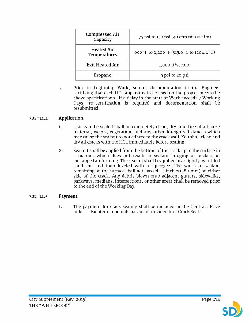
City Supplement (Rev. 2015) Page 274 THE “WHITEBOOK”
Compressed Air Capacity 75 psi to 150 psi (40 cfm to 100 cfm)
Heated Air Temperatures 600 F to 2,200 F (315.6 C to 1204.4 C)
Exit Heated Air 1,000 ft/second
Propane 5 psi to 20 psi
3. Prior to beginning Work, submit documentation to the Engineer certifying that each HCL apparatus to be used on the project meets the above specifications. If a delay in the start of Work exceeds 7 Working Days, re-certification is required and documentation shall be resubmitted.
302-14.4 Application.
1. Cracks to be sealed shall be completely clean, dry, and free of all loose material, weeds, vegetation, and any other foreign substances which may cause the sealant to not adhere to the crack wall. You shall clean and dry all cracks with the HCL immediately before sealing.
2. Sealant shall be applied from the bottom of the crack up to the surface in a manner which does not result in sealant bridging or pockets of entrapped air forming. The sealant shall be applied to a slightly overfilled condition and then leveled with a squeegee. The width of sealant remaining on the surface shall not exceed 1.5 inches (38.1 mm) on either side of the crack. Any debris blown onto adjacent gutters, sidewalks, parkways, medians, intersections, or other areas shall be removed prior to the end of the Working Day.
302-14.5 Payment.
1. The payment for crack sealing shall be included in the Contract Price unless a Bid item in pounds has been provided for “Crack Seal”.

City Supplement (Rev. 2015) Page 275 THE “WHITEBOOK”
SECTION 303 - CONCRETE AND MASONRY CONSTRUCTION
303-1.3 Forms. To Paragraph (11), DELETE in its entirety and SUBSTITUTE with the following:
Exterior forms are required for structures unless otherwise specified on the Plans or in the Specifications.
303-1.8.4 Consolidating. ADD the following:
1. As determined by the Engineer, when rock pockets are detrimental to the steel reinforcement, the Engineer may allow you to repair in accordance with 303-1.9.2, “Ordinary Surface Finish”.
303-5.1.1 General. To Paragraph (2), Sentence (1), DELETE in its entirety and SUBSTITUTE with the following:
Unless otherwise shown on the Plans, and except as otherwise specified in 303-5.1.3, “Driveway Entrances” the minimum thickness of walks shall be 4 inches (101.6 mm).
ADD the following:
1. In areas where field adjustments to the curb and gutters may be required due to the existing conditions to maintain positive drainage, you shall contact the Engineer prior to the construction.
2. You shall exercise due caution when working around trees not to damage either the trunk or any of its limbs. If damage to a tree occurs, you shall notify the Engineer. Once excavation has occurred, all efforts shall be made to mitigate the exposure of the tree roots to the air.
3. You shall complete the Work within 5 Working Days after demolition.
4. You shall restore the asphalt along the gutter line only between 7 Days to 14 Days after the placement of the curb and gutter.
5. Unless specified otherwise, the depressed curb and gutter shall be replaced monolithically with the driveway when the driveway is to be removed and replaced.
6. If curbs, gutters, or sidewalks are replaced, you shall duplicate the existing surrounding score pattern and color. The score pattern and color shall be approved in advance by the Engineer.
ADD:
303-5.1.4 Historical Stamps and Impressions.
1. You shall remove and relocate the existing Contractor date stamp and Impression and street name stamps outside the pedestrian travel way to the parkway area or face of sidewalk. The stamp’s position shall be such

City Supplement (Rev. 2015) Page 276 THE “WHITEBOOK”
that it can be read from the street and as close as practical to the stamp’s original location.
2. If it is determined that the date stamps or impressions cannot be relocated or they are damaged and the Plans designate the stamps or impressions to be removed, you shall saw cut them to full depth at a minimum distance 2 inches (50.8 mm) away from the edge of the stamp. Carefully remove, bag, label, and set the date stamps or impressions aside on Site in a location designated by the Engineer for pickup by others. You shall stamp the current Contractor’s name and date in concrete.
303-5.3 Placing Concrete. ADD the following:
1. The top and face of the finished concrete surfaces shall be true and straight, of uniform width, and free of humps, sags, or other irregularities. The finished concrete surface shall not vary more than 0.02 feet (6.1 mm) from a 10 feet (3 m) straight edge, except at grade changes or curves. No freestanding water will be permitted on slopes over 1%. No freestanding water deeper than 1/16 inch (1.6 mm) shall be permitted on slopes of less than 1%.
2. Concrete placed immediately before rain shall be protected to prevent contact with rainwater. Protective covering shall be kept on hand at all times for this purpose.
303-5.5.3 Walk. ADD the following:
1. If the continuous sidewalk length equals a block or more, your name and the year in which the improvements is constructed shall be stamped therein to a depth of ¼ inch (6.4 mm) in letters not less than ¾ inch (19.1 mm) high, at a location determined by the Engineer.
2. You shall coordinate the root pruning activities in accordance with 801-7, “Maintenance of Existing Trees”.
303-5.5.5 Alley Intersections, Access Ramps, and Driveways. REVISE “wood float” to “steel trowel followed with a medium coarse broom”.
303-5.6 Curing. To Paragraph (3), Sentence (2), DELETE in its entirety and SUBSTITUTE with the following:
The placement of bituminous pavement or cement treated base adjacent to concrete curb, gutter, or alley intersections shall not be permitted until the seventh day following the placement of concrete nor shall concrete paving operations be permitted until the seventh day where placing or finishing equipment will ride on the previously placed concrete.
303-5.9 Measurement and Payment. ADD the following:
1. The payment for the preservation of date stamps and impressions shall be included in the Bid item for “Contractor Date Stamps and Impressions”.
City Supplement (Rev. 2015) Page 277 THE “WHITEBOOK”
2. The payment for removing tree roots, cutting, excavation, disposal, import and backfilling to grade, and pavement construction shall be included in the items of Work for which the subgrade is prepared.
3. At locations where the width of the walk is being reduced, the payment for removing the existing walk shall be included in the Bid item for “Remove and Replace Existing Sidewalk”.
4. Additional curb and gutter removal, disposal, and replacement adjacent to the Work on a proposed curb ramp shall be required as directed by the Engineer. The payment for the additional removal, disposal, and replacement of the curb and gutter shall be included in the Bid item for “Additional Curb and Gutter Removal and Replacement”.
5. The payment for the additional removal, disposal, and replacement of sidewalk shall be included in the Bid item for “Additional Sidewalk Removal and Replacement”.
6. The measurement shall be made of actual areas and depths authorized by the Engineer and shall be calculated as cubic yards in place. Excavation, grading, and backfilling shall be included in the Bid items for the Work of sidewalks, curb ramps, or curb and gutters.
ADD:
303-5.10 Curb Ramp Construction.
303-5.10.1 Installation.
1. Prior to Bid, you shall evaluate the Site to determine existing conditions and actual limits of Work to ensure if the installation of compliant curb ramps is possible. You shall obtain the Engineer’s approval of the layout of the curb ramp prior to construction.
2. To allow for proper drainage, the slope of the landing to the street shall not be less than 1.0%. The slope of the ramp shall not exceed 1 unit vertical to 12 units horizontal or 8.33%. The slope of the sides and flares shall not exceed 1 unit vertical to 10 units horizontal or 10.0%.
3. The Detectable Warning Tile (DWT) shall be installed in accordance with the manufacturer’s specifications by installer certified in writing by the Supplier.
4. The DWT shall be oriented such that the rows of domes are parallel with the direction of the ramp. When multiple tiles (regardless of size) are used, the domes shall be aligned between the tiles and throughout the entire detectable surface installation. The edge of the tile(s) nearest the street shall be between 6 inches and 8 inches (152.4 mm and 203.2 mm) from the gutter flow line. You shall trim and refinish the edges of the DWT in accordance with the manufacturer’s recommendations. Field trimming of stainless steel DWT shall not be allowed.

City Supplement (Rev. 2015) Page 278 THE “WHITEBOOK”
5. The DWT shall be used as shown on the Plans. You shall not change the material specified without the written approval of the Engineer.
6. You shall submit an approved TCP, including an accessible pedestrian access plan, through the construction zone with approved signage. You shall not replace more than 2 curb ramps in one intersection at the same time and shall only demolish those curb ramps that can be replaced within 2 consecutive Working Days in the same week. You shall provide approved temporary accessible curb ramps if necessary to provide access to the designated alternate route areas.
7. Modified curb ramps shall be constructed as shown on the Plans.
303-5.10.2 Payment.
1. The payment for each curb ramp shall include transition areas, landings, DWTs, demolition and disposal, forming, relocating or raising items in conflict to grade, protecting and preserving existing survey monuments and improvements, and restoring pavement.
2. Additional concrete sidewalk and curb quantities beyond 15 feet (4.6 m) shall be included in the Bid items for “Additional Sidewalk” and “Additional Curb”.
3. Unless otherwise specified in the Special Provisions, the payment for each modified curb ramp shall include transition areas, landings, DWTs, demolition and disposal, forming, relocating or raising items in conflict to grade, protecting and preserving existing survey monuments and improvements, and restoring pavement
ADD:
303-6.1.1 Stamped Concrete Pavement.
1. Stamped concrete pavement shall be constructed in accordance with the following conditions:
a) Prior to construction, a test section at least 5 feet by 5 feet (1.5 m by 1.5 m) shall have approval of the test section it will be designated as the standard for that particular pattern on the subject Project.
b) When required by the Engineer, skid resistance shall have a minimum acceptance value of 0.35 for either ASTM E-274 or California Test Method No. 342.
c) Visual inspection of the Work shall be performed to determine that the surface texture is as rough as the approved test section and the surface flatness is as flat as the approved test section.
d) Concrete color and method of application shall conform to 303-7, “Colored Concrete”.
e) Coloring and curing compounds used in the Work shall be from the same manufacturer and batch lot.

City Supplement (Rev. 2015) Page 279 THE “WHITEBOOK”
f) The thickness of the concrete paving shall be increased by ½ inch (12.7 mm) over what is required on the Plans.
g) The pavement section shall be PCC, Class 560-C-3250, placed in accordance with 302-6, “Portland Cement Concrete Pavement”.
h) There shall be no cold joint between the structural PCC pavement section and the stamped surface layer. The stamped surface layer shall not be less than 4 inches (101.6 mm) thick.
i) The final finishing for textured, stamped, or colored concrete paving shall be in accordance with 302-6.4.4, “Final Finishing” subject to the following conditions:
i. Stamping shall be performed before the initial set of the concrete. No water shall be added to the surface.
ii. A flat surface shall be maintained. Rounding shall not be allowed.
iii. Limited to a running bond pattern.
iv. ¼ inch (6.4 mm) wide maximum groove with ¼ inch (6.4 mm) deep maximum imprint.
v. Portland cement concrete shall not be placed in air temperatures exceeding 85º F (29.4º C).
vi. A heavy broom finish, perpendicular to the traveled way, shall be used.
vii. Wax curing or wax sealing shall not be permitted.
303-6.5 Measurement and Payment.
1. The Work for stamped concrete pavement shall be paid for in the square foot Bid item for “Stamped Concrete Pavement”. If no Bid item has been provided, the payment shall be included in the Contract Price.
2. Stamped Concrete Pavement that is colored in accordance with 303-7, “Colored Concrete” shall be included under the square foot Bid item for “Stamped Colored Concrete”.
ADD:
303-7.5 Measurement and Payment.
1. Colored concrete shall be paid for by the square foot Bid item for “Colored Concrete”.
303-8.1 General. ADD the following:
1. Work shall be performed by a qualified installer meeting the following requirements:
a) The installer shall have successfully completed pervious concrete installation similar in design material and the extent indicated in the Work.
b) Utilize a supervisor holding a current certificate from the National Ready Mixed Concrete Association Pervious Concrete Installer Certification program.

City Supplement (Rev. 2015) Page 280 THE “WHITEBOOK”
c) At least 1 in 3 installers shall hold a current certificate from the National Ready Mixed Concrete Association Pervious Concrete Technician Certification program.
2. Proof of installation qualifications shall be submitted prior to pervious concrete installation.
3. A mandatory pre-placement conference shall take place and shall include, at a minimum, you, the engineer, the pervious concrete contractor, the concrete Supplier, and the field testing agency. All materials and personnel qualifications, concrete production, preparation, placing, curing, and testing procedures will be reviewed to ensure specification compliance.
303-8.3 Subgrade. DELETE in its entirety and SUBSTITUTE with the following:
1. The subgrade preparation shall follow the requirements of 301-1, “Subgrade Preparation”. The subgrade shall not be treated or stabilized with Portland cement or lime. If the pervious concrete is being installed directly on the subgrade, the subgrade shall be moistened to prevent it from absorbing moisture from the concrete.
303-8.5 Placement. To Paragraph (2), DELETE in its entirety and SUBSTITUTE with the following:
Pervious concrete shall be uniformly deposited over the entire formed area. Strike off and spreading shall be performed using a self-propelled or manual vibratory roller screed or a laser screed. Hand-rodding may be used in areas inaccessible to the roller-screed if so approved by the Engineer. Strike off shall be no greater than ¾ inch (19.1 mm) above the forms to allow for compaction. Compaction shall be performed using a self-propelled roller screed or a minimum 10 inches (254 mm) steel roller that exerts at least 10 psi (68.9 kPa) on the concrete surface. Adjacent to the edge of each form, hand tampers shall be used for compaction.
To Paragraph (4), DELETE in its entirety and SUBSTITUTE with the following:
After compaction, the surface shall be protected from rapid evaporation by water fogging, covering with 6 mil (150 μm) polyethylene sheeting, or the application of a chemical evaporation retardant approved by the Engineer.
303-8.7 Curing. DELETE in its entirety and SUBSTITUTE with the following:
1. Curing shall consist of covering the surface and, as necessary, the application of water. Curing shall begin within 20 minutes of placement or within 15 minutes when the wind is in excess of 5 miles per hour (8 kilometers per hour). The surface shall be securely covered with polyethylene sheeting having a minimum thickness of 6 mils (150 μm).
2. Sheeting shall be secured using lumber, rebar, stakes, or by other approved methods by the Engineer. Sand or dirt shall not be used to secure the sheeting.

City Supplement (Rev. 2015) Page 281 THE “WHITEBOOK”
3. The cover shall be checked daily to verify that it has not been displaced or damaged, and that condensation is evident underneath the sheeting. Damaged sheeting shall be repaired. Displaced sheeting shall be replaced. When there is no observable condensation, 1.5 gallons of water per square yard (5.7 L/m2) shall be applied to the surface. The cover shall remain securely in place for a minimum of 7 Days.
ADD:
303-9 PERMEABLE INTERLOCKING CONRETE PAVERS.
303-9.1 General
1. Permeable interlocking concrete pavers shall conform to 202-4, “Permeable Interlocking Concrete Pavers”.
2. Work shall be performed by a qualified installer meeting the following requirements:
a) Submit documentation showing comparable concrete paver installation similar in scope, design material, and extent indicated on the Plans has been successfully installed within the past 5 years or more of documented performance record for the proposed product and has been successfully performed by the installer and its personnel assigned to the concrete paver installation for this project.
b) Holds a current certificate from the Interlocking Concrete Pavement Institute Concrete Paver Installer Certification program.
303-9.2 Construction Test Section.
1. Construct a test section using the same method and crew performing the installation. The test section shall be a minimum of 100 ft2 (9.3 m2). The test section shall be tested to determine the surcharge of the bedding layer, joint sizes, and lines, laying pattern, color, and texture of the job. The test section may be incorporated in the Work if approved by the Engineer. The Engineer shall be notified at least 24 hours in advance of construction of the test section.
303-9.3 Subgrade.
1. The subgrade preparation shall conform to 301-1, “Subgrade Preparation”.
303-9.4 Base/Subbase.
1. The base/subbase aggregate installation shall comply with 301-6, “Permeable Pavement Structural Base and Subbase”.
303-9.5 Bedding.
1. The bedding aggregate installation shall comply with 301-7, “Permeable Interlocking Concrete Pavers Bedding”. Do not subject screeded bedding material to any pedestrian or vehicular traffic before paving unit installation begins.

City Supplement (Rev. 2015) Page 282 THE “WHITEBOOK”
303-9.6 Paving Unit Placement.
1. Paving units can be installed by manual methods or with mechanical equipment. The paving units shall be laid in the pattern(s) and joint widths shown in the Plans. The straight pattern lines shall be maintained.
2. Fill gaps at the edges of the paved area with cut paver units. Cut pavers subject to tire traffic shall be no smaller than 1/3 of a whole unit.
3. Openings and joints shall be filled with the fill material identified in the Plans. Excess fill aggregate on the surface shall be removed by sweeping the pavers clean.
4. The pavers shall be compacted and seated into the bedding material using a low-amplitude, 75-90 Hz plate compactor capable of at least 5,000 lbf (22 kN) centrifugal compaction force. At least 2 passes with the plate compactor shall be required. Compaction within 6 feet (1.8 m) of an unrestrained edge shall not be performed.
5. After compaction, additional filling aggregate shall be applied as needed and the cleaning and compaction process repeated.
6. The final surface tolerance of compacted pavers shall not deviate more than ± 3/8 inches over 10 feet (± 9.5 mm over 3 m).
303-9.7 Acceptance.
1. Permeable interlocking concrete pavers shall have an infiltration rate of a minimum of 100 inches per hour (254 cm/hr) when tested.
2. Adjacent pavers shall be no greater than 1/8 inch (3.2 mm) difference in height. Final elevations shall be checked for conformance to the Plans.
303-9.8 Measurement and Payment.
1. The payment for permeable interlocking concrete pavers shall include installation as shown on the Plan or as directed by the Engineer and shall be included under the square foot Bid item for “Permeable Interlocking Concrete Pavers”.

City Supplement (Rev. 2015) Page 283 THE “WHITEBOOK”
SECTION 304 - METAL FABRICATION AND CONSTRUCTION
ADD:
304-5 PAYMENT.
1. The payment for signs shall include footing, post, sign, all required hardware, and installation in accordance with the Contract Documents and shall be included in the Contract Price unless a Bid item has been provided.

City Supplement (Rev. 2015) Page 284 THE “WHITEBOOK”
SECTION 306 - OPEN TRENCH CONDUIT CONSTRUCTION
ADD:
306-3.3.1 Removal and Abandonment of Existing Water Facilities.
1. Existing facilities shall be abandoned unless indicated otherwise in the Contract Documents. Any gate valve to be removed shall be removed entirely with the valve casing and cover. Any gate valve to be abandoned shall be abandoned in place by removing the cover and casing to subgrade, filling the remaining valve casing with sand or Controlled Low Strength Material (CLSM) in accordance with 201-6, “Controlled Low Strength Material”, and restoring the pavement. Gate valves abandoned prior to construction, with a lid and casing found within the Project limits, shall be properly abandoned as stated above and paid for as Extra Work, as approved by the Engineer.
2. Any existing fire hydrant which is served by a main to be abandoned shall be abandoned with its services, unless otherwise shown on the Plans. Fire hydrant services to be abandoned shall be blind flange or cut and plugged at least 12 inches (304.8 mm) below finish grade or below the top of curb, whichever is lower.
3. Where portions of the old main, services, or both are abandoned and left in place, the exposed ends of the abandoned main shall be tightly plugged with concrete and service ends shall be crimped, unless otherwise shown on the plans. Abandoned water services shall be located and shut off at the main.
4. Existing meter boxes previously abandoned within the Project limits shall be removed as specified.
5. Voids resulting from abandoned or removed water services and meter boxes shall be filled with suitable material compacted to a relative compaction of 90% and concrete capped. For 16 inches (406.4 mm) and larger water mains, the abandoned pipe shall be filled with sand or CLSM in accordance with 201-6, “Controlled Low Strength Material (CLSM)”.
6. Salvaged material from the abandoned water mains and its appurtenances, except fire hydrant bodies, shall become your property at the time of removal from the trench, unless otherwise specified or shown on the Plans. Such material shall not be allowed to accumulate along the line of Work, but shall be removed from the area at the earliest practical time.
7. You shall notify the Public Utilities Department 48 hours in advance of abandonment to obtain the delivery location for salvaged fire hydrant bodies.

City Supplement (Rev. 2015) Page 285 THE “WHITEBOOK”
306-3.3.2 Abandonment of Sewer Facilities.
1. You shall plug existing sewer mains to be abandoned at downstream locations identified on the Plans as approved by the Engineer. You shall monitor the abandonment for a 48 hour period to ensure that there is no flow in the existing main or laterals. If there is flow in the existing main, you shall perform a dye pack test to confirm that the abandonment has been successfully completed.
2. Sewer mains to be abandoned in place shall be completely filled with CLSM in accordance with 201-6, “Controlled Low Strength Material (CLSM)” or a combination of sand. Plug both ends of each pipe segment with concrete plugs. You shall demonstrate to the Engineer that conduits being abandoned are completely filled as evidenced by the filler material flowing through ventilation holes and through the ends of pipe segments. You shall submit the method of abandonment, the materials to be used, and the locations and sizes of the ventilation holes to the Engineer.
3. You shall notify the Public Utilities Department 48 hours in advance of abandonment to obtain the delivery location for salvaged manhole lids and frames.
4. You shall ensure that the proposed sewer laterals have been successfully connected to the proposed sewer mains and that water tight capping or plugging has been completed before abandoning any existing sewer main and laterals. Sewer laterals to be abandoned shall be plugged with concrete at the property line or as located in the Site by the Engineer in the vicinity of the property unless otherwise shown on the Plans.
5. Any existing cleanout accessing a main to be abandoned shall be abandoned. Cleanouts and risers to be abandoned shall be cut and plugged at least 3 feet (0.9 m) below finish grade or below the top of curb, whichever is lower.
a) In non-paved areas, the remaining voids shall be filled with suitable material compacted to a relative compaction of 90% and concrete plugged.
b) For paved areas, the remaining voids shall be filled with CLSM or a combination of sand and shall be concrete plugged. Pavement shall be restored.
306-3.3.3 Payment.
1. The payment for removing, plugging, and abandoning existing water facilities and appurtenances within the proposed trench zone shall be included in the Bid items for the new water facilities Work.
2. The payment for removing, plugging, and abandoning existing water facilities and appurtenances outside the proposed trench zone as

City Supplement (Rev. 2015) Page 286 THE “WHITEBOOK”
shown on the Plans shall be included in the Bid item for “Removal or Abandonment of Existing Water Facilities”.
3. For 16 inch (406.4 mm) and larger water mains and appurtenances to be abandoned outside of the trench limits, the payment shall be included in the Bid item for “Large Water Main Abandonment”.
4. The payment for service laterals to be plugged and abandoned in place shall be included in the Bid item for the sewer main Work.
5. The payment for sewer mains to be filled and abandoned in place shall be included in the Bid item for “Abandon and Fill Existing Sewer Main Outside of the Trench Limit”.
6. The payment for the abandonment of existing manholes outside the trench area, including the concrete plugs, shall be included in the Bid item for “Abandon Existing Manhole Outside of Trench Limit”.
7. The payment for removing meter boxes previously abandoned within the Project limits shall be included in the Bid item for “Removal of Abandoned Water Meter Box”.
8. The payment for the abandonment of cleanouts shall be included in the Bid item for abandoning the main unless a Bid item for “Abandon and Fill Cleanout” has been provided.
306-3.3.4 Asbestos Materials.
1. If you identify asbestos containing materials (ACM) at the Work Site, you shall immediately stop Work in the affected area and notify the Engineer unless the Contract Documents show the presence of such materials.
306-3.3.4.1 Non-Friable Asbestos Cement Pipe (ACP).
1. You shall take adequate care to maintain the materials in a non-friable state. You shall be responsible for the ACM removal and the associated contamination clean-up resulting from improper handling.
2. Removal of ACP shall be in whole sections where possible. You shall comply with the following requirements for ACP that is to be cut or broken:
a) Evacuate the area of unauthorized personnel, post warning signs, and provide adequate barriers to keep unauthorized personnel out of the area.
b) Provide the workers performing the cutting or breaking of asbestos material with personal protective equipment in compliance with respiratory protection requirements of EPA or Title 8, §5144 (whichever is more stringent) as applicable to the Work.
c) Cutting or breaking of asbestos material to facilitate removal shall be in compliance with California Regulations, Title 8, §1529. You shall only perform cutting of ACP using a hydraulic

City Supplement (Rev. 2015) Page 287 THE “WHITEBOOK”
snap cutting method. All powered and hand operated saws shall not be allowed.
d) If a collar needs to be broken to remove whole ACP sections, a wet cloth shall be placed on the collar and water shall be used throughout the process to wet the collar. Minimal force shall be used to break it into as few large pieces as possible. Areas to be cut or broken shall be adequately wetted with amended water to reduce fiber emission. Your cutting and removal method shall minimize fiber release. Related debris from the cutting or breaking of asbestos material shall be considered friable.
e) ACP shall be wrapped in 6 mil (150μm) polyethylene sheeting or bags, sealed with appropriate tape, and properly labeled and removed away from the construction area to prevent damage.
f) You shall transport the wrapped and sealed ACP to a designated secure disposal bin on the Site no later than the end of each Working Day. The bin shall be lockable or located within a secure construction area.
g) You shall comply with City of San Diego Miramar Landfill Acceptance Criteria for the Disposal of Non-Friable Asbestos Waste requirements. A copy of the requirements is available by calling (858) 573-1415 or online at:
http://www.sandiego.gov/environmental-services/ep/hazteam/nonfasbestos.shtml
h) You shall be responsible for providing your own certification of non-friability.
i) You shall provide notice to the Engineer a minimum of 5 Working Days prior to the transportation of the ACP disposal bins or friable asbestos waste. Copies of all manifests shall be submitted to the Engineer for review 48 hours in advance of transport.
j) Only the City’s Asbestos and Lead Program representative shall sign the manifests as the generator.
k) Friable asbestos wastes are regulated as hazardous waste (California Code of Regulations, Title 22, Division 4.5, Chapter 11, Article 3, §66261.24) and shall be transported by a licensed hazardous waste hauler and disposed of at an appropriate landfill.
306-3.3.4.2 Asbestos Cement Pipe Training.
1. You shall comply with the provisions of California Title 8, §5208 and §1529, and Title 40 CFR Part 61.Your workers handling ACP shall be trained in accordance with Title 8 CCR §1529 regarding the dangers inherent in handling asbestos materials and breathing asbestos dust, proper Work procedures, and personal and area protective measures. Topics covered in a state accredited course for ACP shall include the following:
a) Methods of recognizing asbestos.

City Supplement (Rev. 2015) Page 288 THE “WHITEBOOK”
b) Health effects associated with asbestos.
c) Relationship between smoking and asbestos in producing lung cancer.
d) Nature of operations that could result in exposure to asbestos.
e) Importance of and instruction in the use of necessary protective controls, practices, and procedures to minimize exposure including:
i. Purpose, proper use, fitting, instructions and limitations of respirators as required by 29 CFR 1910.134.
ii. Appropriate Work practices for the ACP Work. Work practices shall include hands-on training.
306-3.3.4.3 Asbestos Cement Pipe Submittals.
1. You shall submit the following information to the Engineer prior to the start of the Work:
a) A Work plan showing the means and methods of performing the Work, disposal bin locations and details on how they will be secured, information about the disposal transporter and disposal locations, and information on how you will handle friable asbestos waste if any is generated.
b) Copies of notifications made to regulatory agencies, if required.
c) Evidence that workers handling ACP have been trained, certified, and accredited as required by law.
d) If respirators are going to be used for the non-friable Work, submit a doctor’s report from medical examinations conducted within the last 12 months as part of compliance with OSHA medical surveillance requirements for each worker who is to enter the Site. You shall submit, at a minimum, the following for each worker:
i. Name and Social Security Number.
ii. Physician’s written opinion from the examining physician including the following:
Whether the worker has any detected medical conditions that would place the worker at an increased risk of material health impairment from exposure to asbestos.
Any recommended limitations on the worker or recommendations on the use of personal protective equipment such as respirators.
A statement that the worker has been informed by the physician of the results of the medical

City Supplement (Rev. 2015) Page 289 THE “WHITEBOOK”
examination and of any medical conditions that may result from asbestos exposure.
e) You shall not start Work until the submittals are returned with the City’s Asbestos and Lead Management Program’s written approval.
2. You shall submit the following information to the Engineer immediately following the removal and disposal of ACP:
a) Copies of all waste shipment records.
b) Copies of all air monitoring results taken during the removal in compliance with OSHA. Air sample results shall be submitted to the Engineer within 24 hours.
306-3.3.4.4 Friable Asbestos.
1. Any friable asbestos (material that can be crumbled, pulverized, or reduced to powder in hand) or soil that is contaminated with friable asbestos are regulated as hazardous waste (California Code of Regulations, Title 22, Division 4.5, Chapter 11, Article 3, §66261.24). The City reserves the right to select another qualified Contractor to perform the Work related to friable asbestos materials.
306-3.3.4.5 Payment.
1. The payment for the handling and disposal of asbestos-containing materials shall be paid for as Extra Work unless a Bid item has been provided for “Handling and Disposal of Non-friable Asbestos Material”.
ADD:
306-3.7 Imported Backfill.
1. If you elect to import material from a source outside the project limits for use as backfill, the backfill material, delivery of samples, suitability, and placement method shall be in accordance with 217-2.3, “Imported Backfill”.
2. Should the imported material not be substantially the same as the approved sample, it shall not be used for backfill and shall be removed from the Work site at your expense.
3. The densification method for imported material authorized by the Engineer shall be dependent upon its composition, the composition of the in-place soil at the point of placement, and the relative compaction to be obtained.
306-4 SHORING AND BRACING. ADD the following:
1. Shoring is considered to be the adequate sheeting, shoring, bracing, or equivalent method for the following:
City Supplement (Rev. 2015) Page 290 THE “WHITEBOOK”
a) The protection of life and limb which shall conform to applicable safety orders.
b) The protection of existing underground and above-ground private and public improvements.
c) The remedy of any and all conditions encountered, regardless of depth, during the construction of the Project.
2. You shall take appropriate measures when trenching adjacent to the existing utilities to prevent the existing utility trench from sloughing into the new trench excavation. The wall of the new trench may be adjacent to the edge of the existing trench and therefore may contain loose material. You are required to use adequate shoring or other protective construction measures as required by field conditions to prevent damage to pavement outside the trench width and to prevent sloughing of the trench wall.
3. You shall be responsible for any sloughing and damage to the road surface or other utilities that may occur. It shall be your responsibility to repair any damaged pavement or utilities as a result of the sloughing.
306-6.3 Bedding for Plastic Pipe and Fittings. ADD the following:
1. CLSM shall be used for bedding and backfilling when HDPE pipe is installed in paved areas, where pipe crosses utility easement, and at locations where pipe is to be backfilled with concrete as shown on the Plans. CLSM shall conform to 201-6, “Controlled Low Strength Material (CLSM)” and the following concrete classes or as designated in the Contract Bid item or shown on the Plans:
a) 190-E-400 in residential and local streets.
b) 380-E-800 in major and arterial streets.
2. The concrete backfill shall be placed in the trench against undisturbed material at the sides and bottom of the trench and in a manner that shall prevent floating or shifting of the pipe and that shall prevent voids in or segregation of the concrete. Foreign material which falls into the trench prior to or during the placement of concrete shall be immediately removed. Where necessary, earth plugs shall be constructed and compacted at the ends of the planned concrete backfill to contain the concrete within the trench.
3. The surface of the concrete backfill shall be finished with a heavy broom to produce a uniform rough surface if asphalt concrete is to be placed directly.
4. No material shall be placed on top of the concrete backfill until 24 hours after placing the concrete backfill.
5. Bedding material for irrigation pipe, direct burial control wire, and electrical conduit shall be SE 50, plaster, or mortar sand in accordance with 200-1.5, “Sand”.
City Supplement (Rev. 2015) Page 291 THE “WHITEBOOK”
306-6.5.1 General. ADD the following:
1. When jetting, care shall be exercised to avoid floating of the pipe.
2. For PVC water pipes, sand equivalent shall be SE 50. SE 30 or higher may be substituted for SE 50 as bedding material if all of the following requirements are met:
a) The top of the pipe and haunch areas are mechanically compacted by means of tamping, vibrating roller, or other mechanical tamper.
b) Equipment is of size and type approved by the Engineer.
c) 90% relative compaction or better is achieved.
3. PVC sewer pipes shall be bedded in 3/8 inch (9 mm) crushed rock in accordance with 200-1.2, “Crushed Rock and Rock Dust”.
4. The bedding material shall either be sand, crushed aggregate, or native free-draining granular material. 100% of the bedding material shall pass the no. 4 sieve, shall have a sand equivalent of not less than 50, and shall have an expansion when saturated with water of not more than 0.5%.
5. For storm drains and all types of non-PVC sewer mains, ¾ inch (19 mm) crushed rock in accordance with 200-1.2, “Crushed Rock and Rock Dust” shall be placed to a depth of 4 feet (1.2 m) below the outside diameter of the pipe or 1 inch (25.4 mm) below the bell of the pipe, whichever is greater.
306-7.1 General. To Table 306-7.1, ADD the following:
Gravity Pipe Material Material
Specification Installation
Specification
Perforated PVC Plastic Pipe 207-17.7 306-11
306-7.7.1 General. To Paragraph (1), ADD the following:
g) Perforated PVC Plastic Pipe conforming to 207-17.7, “Perforated PVC Plastic Pipe”.
ADD:
306-7.7.2.4 Fiberglass Reinforced Polymer Mortar (FRPM) Pipe.
1. Each section of pipe shall be moved or installed using approved non-metallic slings. The slings shall support each pipe section at a minimum of 2 locations in such a way that the pipe is not damaged by flexure or abrasion. Submit detailed drawings of slings proposed for the handling of the pipe during production, loading, unloading, and installation.
2. The installation depth of CCFRPM pipe shall be limited to a minimum cover of 5 feet (1.5 m) to a maximum of 15 feet (4.6 m) including cover, unless a special design is approved by the Engineer.
City Supplement (Rev. 2015) Page 292 THE “WHITEBOOK”
306-7.8.2.1 General. ADD the following:
1. Testing of the completed pipeline shall be performed in sections between test bulkheads after all anchors and appurtenances have been installed and after backfilling has been completed. Install the test bulkheads at locations approved by the Engineer. Pressure testing against closed valves shall not be allowed.
2. Pressure testing of pipe and fittings at the lowest elevation shall be performed at 150% of the specified test pressure and no less than 100% of the specified test pressure at the highest elevation.
3. Side outlet valves to be furnished with blind flanges shall be tested while uncovered to allow visual inspection for valve leakage during the required field hydrostatic test.
4. An optional field hydrostatic test may be permitted by the Engineer. The duration of the test shall be 1 hour with pumping discontinued at the specified pressure.
5. In the event that the rate of loss of water during the test method exceeds the acceptable rate, you shall locate the leaks and perform the required repairs. Regardless of the outcome of the test, all detectable leaks shall be repaired by you at your expense. Additional testing shall be performed until satisfactory results have been completed. The connections to existing pipelines shall be tested at line pressure after refilling the existing pipelines. Repair all leaks in the connections which occur as a result of testing operations.
6. Leakage shall not be allowed for steel (flanged or welded) and ductile iron (flanged) pipe. You shall provide accurate means for measuring the quantity of water lost. The allowable leakage for all other pipe shall be 15 gallons per inch (2.3 L/mm) of diameter per mile of pipeline within 24 hours.
306-7.8.2.4 Air Pressure Test. ADD the following:
1. For PVC sewer mains, minimum gauge pressures, test durations, acceptance requirements, and gauge certifications shall be in accordance with 306-7.8.2.4.1, “Air Pressure Test for PVC Sewer Mainlines”.
ADD:
306-7.8.2.4.1 Air Pressure Test for PVC Sewer Mainlines.
1. Air pressure test sewer lines after laying, backfilling, and compaction. Air pressure testing shall not be required for sewer main replacements where live laterals are connected to the new main.
2. The test section shall be pressurized to 3.5 psi (24.1 kPa) and shall be held above 3.0 psi (20.7 kPa) for not less than 5 minutes. Air shall be added if necessary to keep the pressure above 3.0 psi (20.7 kPa).
City Supplement (Rev. 2015) Page 293 THE “WHITEBOOK”
3. When the prevailing groundwater is above the pipe being tested, air pressure shall be increased 0.43 psi (3 kPa) for each foot the water table is above the invert of the pipe.
4. The pressure gauge used shall be supplied by you, shall have minimum divisions of 0.1 psi (0.7 kPa), and shall have an accuracy of 0.04 psi (0.3 kPa). Certified testing shall verify the accuracy and the calibration of the gauge firm annually or when requested by the Engineer.
5. At the end of the 5 minute saturation period, note that the pressure shall be at a 3.0 psi (20.7 kPa) minimum and begin the same lapse required for the air pressure drop. If the pressure drops more than 0.5 psi (3.4 kPa) in less than the time shown in Table 306-7.8.2.4.1, the section of that pipe shall be deemed to have failed the test.
6. For larger diameter pipe use the following formula:
Minimum time in seconds = 1.2 x diameter in mm.

City Supplement (Rev. 2015) Page 294 THE “WHITEBOOK”
TABLE 306-7.8.2.4.1
1 Pipe Dia
(in/cm)
2 Min
Time (sec)
3 L for Min
Time (ft/m)
4 Time For
ADD’l L (sec)
Specification Time for Length (L) Shown (min sec)
100 ft. 30.5 m
150 ft. 45.7 m
200 ft. 61.0 m
250 ft. 76.2 m
300 ft. 91.4 m
350 ft. 106.7 m
400 ft. 121.9 m
450 ft. 137.2 m
4/10.16 1.53 597/181.97 0.190 x L 1:53 1:53 1:53 1:53 1:53 1:53 1:53 1:53
6/15.24 2.50 398/121.31 0.427 x L 2:50 2:50 2:50 2:50 2:50 2:50 2:51 3:12
8/20.32 3.47 298/90.83 0.760 x L 3:47 3:47 3:47 3:47 3:48 4:26 5:04 5:42
10/25.40 4.43 239/72.85 1.187 x L 4:43 4:43 4:43 4:57 5:56 6:55 7:54 8:54
12/30.48 5.4 199/60.66 1.709 x L 5:40 5:40 5.42 7:08 8:33 9:58 11:24 12:50
15/38.10 7.05 159/48.46 2.671 x L 7:05 7:05 8:54 11:08 13:21 15:35 17:48 20:02
18/45.72 8.30 133/40.54 3.846 x L 8:30 9:37 12:49 16:01 19:14 22:26 25:38 28:51
21/53.34 9.55 114/34.75 5.235 x L 9:55 13:05 17:27 21:49 26:11 30:32 34:54 39:16
24/60.96 11.20 99/30.18 6.837 x L 11:24 17:57 22:48 28:30 34:11 39:53 45:35 51:17
27/68.58 12.45 88/26.82 8.653 x L 14:25 21:38 28:51 36:04 43:16 50:30 57:42 46:54
30/76.20 14.10 80/24.38 10.683 x L 17:48 26:43 35:37 44:31 53:25 62:19 71:13 80:07
33/83.82 15.35 72/21.95 12.926 x L 21:33 32:19 43:56 53:52 64:38 75:24 86:10 96:57
36/91.44 17.00 66/20.12 15.384 x L 25:39 38:28 51:17 64:06 76:55 89:44 102:34 115:23
306-7.8.3.1 General. To Table 306-7.8.3.1, REVISE “Percentage Barrel Deflection Allowed1,2” to “Percentage Barrel Deflection Allowed1, 2, 3, 4”
To the Table notes, ADD the following:
3. Deflections of up to 6.5% of the in-field measured diameter are acceptable for storm drain applications.
4. Inward bell shaped deflection in the pipe barrel shall not be allowed.
City Supplement (Rev. 2015) Page 295 THE “WHITEBOOK”
306-8.2.2.2 Mechanical Joints. ADD the following:
1. Joints and mechanical couplings and nuts and bolts shall be field wrapped with a 3 part wax-tape coating system per AWWA C217.
306-8.2.2.3 Installation of Polyethylene (PE) Film Wrap on Iron Fittings. ADD the following:
1. The requirements of this section shall only apply when special coatings are not required or specified for corrosion protection.
306-8.8 Valves, Hydrants, and Appurtenances. ADD the following:
1. Water valve bypasses for mainlines 16-inch and larger shall be constructed in accordance with the Plans, Reference Specifications, and Standard Drawing SDW-154, “Water Valve Bypass Details For Mainlines 16-Inch And Larger”.
306-8.8.3 Thrust Blocks. DELETE in its entirety and SUBSTITUTE with the following:
306-8.8.3 Thrust Blocks and Anchor Blocks.
1. Where pipe is not restrained, thrust blocks shall be constructed as follows:
a) Thrust blocks shall be constructed of concrete conforming to 201-1, “Portland Cement Concrete”.
b) Concrete thrust blocks shall be constructed in accordance with 303, “Concrete and Masonry Construction” and as shown on the Plans.
c) Concrete blocks shall be constructed between undisturbed ground and fittings to be anchored.
d) The quantity of concrete and the bearing area of the pipe against undisturbed soil shall be as shown on the Plans or Standard Plans.
e) Unless otherwise shown, concrete shall be placed so pipe joints and fittings remain accessible to repairs.
2. At least 10 Working Days prior to the construction of thrust blocks and anchor blocks for 16 inch (406.4 mm) and larger water mains, you shall excavate via potholing and expose the soil to the depth of the proposed water main at locations approved by the Engineer. The Engineer will confirm the design when shown on the Plans or will provide the design details within 10 Working Days after the Engineer has observed the exposed Site.

City Supplement (Rev. 2015) Page 296 THE “WHITEBOOK”
3. If there are conflicts with adjacent utilities that prohibit the installation of the concrete blocks, you shall immediately notify the Engineer.
ADD:
306-8.8.4.1 Water Services.
1. Each service shall have its own meter unless specified otherwise on the Plans. Water Services shall conform to 209-4, “PVC Pressure Pipe” and 212, “Water and Sewer System Valves and Appurtenances”.
ADD:
306-8.8.4.2 Trenchless Method for Water Services.
306-8.8.4.2.1 General.
1. Trenchless methods for the installation of water services shall be used at your discretion or when noted on the Plans.
306-8.8.4.2.2 Submittals.
1. You shall submit the following information:
a) Address and schedule of water services.
b) Method for trenchless construction.
c) Launch and receiving pit and shaft dimensions.
d) Proposed drill path alignment (both horizontal and vertical).
e) Tunnel diameter.
f) Minimum depth of cover.
g) Construction procedure and operation sequence.
h) Tunneling equipment.
2. You shall obtain the Engineer’s approval prior to the start of any boring operations.
306-8.8.4.2.3 Water Service Construction.
1. Copper pipe shall be placed in a perforated sleeve and shall not be pushed or pulled against soil during the installation of water services. The sleeve shall be installed between meter and main launching pits. The sleeve shall be cut flush with walls of meter and main launching pits.
2. The inside diameter of sleeve shall be at least 1 inch (25.4 mm) greater than the outside diameter of the water service. The sleeve tunnel diameter shall not exceed the sleeve diameter by more than 2 inches (50.8 mm) and shall align horizontally within 3 inches (76.2 mm) of

City Supplement (Rev. 2015) Page 297 THE “WHITEBOOK”
meter inlet location. The sleeve material shall be PVC SDR 35 (or higher class). HDPE SDR 21 (or higher class) may be used in lieu of PVC.
3. The construction for each service shall be scheduled to minimize water disruption to the property being served.
306-8.8.5 Acceptance. DELETE in its entirety and SUBSTITUTE with the following:
306-8.8.5 Water Meter Boxes.
1. Water meter boxes that are called out as a Bid items only shall be installed at locations determined by the Engineer.
ADD:
306-8.8.6 Temporary Blowoffs.
1. Caps and plugs installed by you to temporarily close the ends of new mains adjacent to points of connection shall contain 2 inches (50.8 mm) outlets with corporation stops. Corporation stops shall protrude free from thrust blocks and shall be available for use in relieving pressure in the mains prior to connecting. Caps and outlets are your property and shall be removed from the Site after main connections are made.
ADD:
306-8.8.7 Blowoff Valve Assemblies.
1. You shall field verify, with the approval of the Engineer, the final location of each assembly.
ADD:
306-8.8.8 Air and Vacuum Valve Assemblies.
1. You shall field verify, with the approval of the Engineer, the final location of each enclosure.
ADD:
306-8.8.9 Out-of-Service Fire Hydrant Discs.
1. The out-of-service hydrant discs shall conform to the following:
a) Constructed of heavy-duty plastic and shall have an inside diameter large enough to easily slide over the large port of a fire hydrant and a minimum outside diameter of 11¼ inch (287.8 mm). Refer to Standard Drawing SDW-104 for “Fire Hydrant Installation”
b) Minimum of 1/16 inch (1.6 mm) thick.
c) Resistant to tearing, ripping, extreme changes in temperature, and vandalism.
d) Of a highly visible color of red.
City Supplement (Rev. 2015) Page 298 THE “WHITEBOOK”
2. Unless specified otherwise in the Special Provisions, you shall maintain City provided out-of-service hydrant discs on the large port of every newly installed fire hydrant immediately after it has been bolted in place and existing assemblies that have been taken out of service. You shall unscrew the cap on the large port, place the disc on the port, and securely replace the cap.
3. You shall ensure that the out-of-service hydrant discs remain on the fire hydrants until the new main has been connected to the existing main and accepted.
4. Once in service, City Forces will remove and retain the out-of-service hydrant discs.
ADD:
306-8.8.10 Acceptance.
1. Acceptance testing for valves and appurtenances shall conform to 306-8.9.3, “Testing of Valves and Appurtenances”. Valves and appurtenances shall be pressure tested at the same time connecting pipelines are pressure tested. Valves, operators, or control and instrumentation elements whose pressure rating is less than the test pressure shall be protected or isolated during pressure testing.
306-8.9.4.1 General. ADD the following:
1. New water mains shall be disinfected and tested in accordance with AWWA C651 and State Health Department requirements. The City will perform a chlorine residual test prior to flushing and a bacteriological test after flushing. No main shall be placed in service until the results of the bacteriological tests are announced as satisfactory.
306-9.1 General. ADD the following:
1. Cast-in-place non-reinforced concrete pipe shall not be allowed for use in San Diego.
306-11 Not Used. DELETE in its entirety and SUBSTITUTE with the following:
306-11 GREEN INFRASTRUCTURE.
306-11.1 Perforated PVC Plastic Pipe Underdrains.
306-11.1.1 General.
1. Trenches for underdrains where perforated PVC pipes are located shall be excavated, the plastic liner placed in accordance with 306-11.3, “Plastic Liner Within Green Infrastructure”, the pipe installed, and the trench backfilled with permeable material according to the dimensions and details shown on the plans. When underdrains are installed in trenches outside the subgrade area, the top 6 inches (152.4 mm) of the trench shall be backfilled, as shown on the plans, with structure backfill conforming to 300-3, “Structure Excavation and Backfill”.

City Supplement (Rev. 2015) Page 299 THE “WHITEBOOK”
2. The underdrain system shall be located above the invert of adjacent storm water systems.
3. To prevent clogging of underdrain from construction sediments, the associated storm water facilities shall be excavated to rough grade. After the contributing drainage area is stabilized, the underdrains and the storm water facilities shall be constructed to achieve the final elevation.
306-11.1.2 Installation.
1. The solid and perforated PVC pipe shall be installed in accordance with 306, “Open Trench Conduit Construction”.
2. The perforated PVC pipe shall be placed such that the perforations are pointed downward. The drainage stone shall be placed and compacted so that it is firm and unyielding prior to placing the pipe. Subsequent backfill shall be in lifts no greater than 8 inches (203.2 mm) and compacted to be firm and unyielding. The underdrain shall be encased in a layer of clean, double washed ASTM D448 No.57 or smaller (No. 68, 8, or 89) stone.
306-11.1.3 Jointing.
1. Jointing of solid PVC pipe shall be securely made in accordance with 306-7.7.2.3, “Jointing of Injection-Sealed PVC Pipe”. Where there is less than 12 inches (304.8 mm) of vertical clearance between the underdrain and the existing water line (or more if indicated on the plans), then no joints shall be within 4 feet (1.2 m) of either side of the existing water line.
2. Perforated PVC pipe shall be connected with belled ends, or with sleeve-type or stop-type couplings under AASHTO M 278. Solvent cementing of joints shall be required.
306-11.2 Underdrain Cleanouts.
306-11.2.1 General.
1. Underdrain cleanout structures shall include in-line wye fittings and stub for access where called for in the plans.
306-11.2.2 Installation.
1. The wells/cleanouts shall be connected to the perforated underdrain with the appropriate manufactured connections. The wells/cleanouts shall be capped with a lockable screw cap. The ends of underdrain pipes not terminating in an observation well/cleanout shall also be capped.
306-11.2.3 Acceptance.
306-11.2.3.1 General.
1. When construction is complete, the contractor shall test all completed underdrain systems for continuous, unimpeded flow.

City Supplement (Rev. 2015) Page 300 THE “WHITEBOOK”
306-11.2.3.2 Test Methods.
1. After backfill and installation is complete, the suggested test methods for each pipe run are as follows:
a) At highpoint or upstream end of underdrain pipe, open cleanout and insert hose from water source.
b) Turn on water.
c) Acceptance of pipe run consists of free flow of water through drain outlet into the existing storm drain structure.
2. Any sections of the underdrain that are clogged or crushed shall be replaced at your expense per the plans and specifications.
306-11.3 Plastic Liner Within Green Infrastructure.
306-11.3.1 General.
1. Plastic liners or PVC geomembranes that are placed within green infrastructure shall be placed in accordance with the following provisions:
306-11.3.2 Pre-Installation Examination and Preparation.
1. Prior to beginning Work, you shall examine previous Work, related Work, and conditions under which this Work is to be performed. This shall include the following:
a) Verify the subgrade is at correct depths, lines, and dimensions for installing the liner.
b) Ensure that overly wet conditions do not exist or are not anticipated to occur during installation, as they will contaminate the liner. Prior to placement, the trench shall have no standing water, mud, debris, or excessive moisture. No liner shall be placed on a subgrade that has become softened by water or overly dried until the subgrade has been properly reconditioned, restored, and re-inspected.
c) Clear any construction debris present within the placement area which may damage the liner. Work is to be sequenced to avoid construction traffic on the exposed liner at any time.
306-11.3.3 Placement.
1. Liner shall be cut, fit to the dimensions, and placed in the trench in accordance with the Plans. Trench sides and bottom shall be excavated to provide a smooth surface, free of obstructions and debris.
2. The liner shall be installed on the bottoms and the sides of the trench and/or on top of the permeable aggregate base and to the elevations in accordance

City Supplement (Rev. 2015) Page 301 THE “WHITEBOOK”
with the plan details. To prevent lateral flow, the hydraulic restriction layer shall extend the full depth of the media to the base of the drainage layer in situations where underdrains are required. In situations where underdrains are not required, the vertical hydraulic restriction layer shall extend to a depth in accordance with the Right-Of-Way Design Manual. At locations where liners are not required in the vertical surfaces of the trench, the liners in the horizontal placements shall be extended and turned up minimum 6 inches (152.4 mm) on the vertical surfaces to provide tight layer separation.
3. Voids between liner and excavation sides shall be prevented during construction. Removing boulders or other obstacles from the trench walls may create such voids. Natural soils shall be placed in these voids at the most convenient time during the construction to ensure liner completely and uniformly conform to the sides of the excavation.
4. During construction, waterproofing membrane shall be held in place by backfilling or other means without puncturing the material. Other methods of pinning can also be used as allowed by the Engineer.
5. No traffic or other equipment shall be allowed directly on the liners.
6. The liners shall have minimum longitudinal and vertical overlaps. Unless specified otherwise, when overlaps are required between rolls, the upstream roll shall overlap the downstream roll in order to provide a shingled effect. If chemical seams are used, the panels shall overlap by 6 inches to 8 inches (152.4 mm to 203.2 mm) with a 4 inches (101.6 mm) wide seam. If thermal seams are used, the single track weld shall overlap 4 inches to 6 inches (101.6 mm to 152.4 mm) with a minimum 2 inches (50.8 mm) wide seam. All seams shall be made in accordance with the manufacturer’s recommendation. If at all possible, seams shall not be located at low points in the subgrade unless the geometry requires seaming to be done at these locations. Field seams shall be inspected and, when ordered by the Engineer, shall be tested and pass the Vacuum Box Test.
7. Before covering with backfill material, the conditions of the liner including all factory seams shall be observed by the inspectors to determine that there are no holes or rips that exist in the liner and all piping or conduit penetrations are properly sealed and welded. Damaged liner material shall be repaired at your expense by placing new material that meets overlap requirements over the damaged area. The liner shall be covered as soon as possible after being inspected, but not later than 7 Days after placement. Material left uncovered for more than 7 Days shall be removed and rejected.
8. All liners shall have a minimum of 3 inches (76.2 mm) top soil and/or mulch covers and they shall not be exposed to any sunlight. After placement of granular fill and soil media, two edges of the liner protruding at the top of the trench shall be anchored to concrete curb or sidewalk. Excess material shall be trimmed neatly such that it is not exposed. Excess liner should not be trimmed until the site is fully stabilized.

City Supplement (Rev. 2015) Page 302 THE “WHITEBOOK”
306-11.3.4 Pipe Penetrations and Pipe Sealant.
1. Provide pipe penetrations and joint sealant sealing systems for all utilities and underdrain penetrations through the liner. Penetrations shall be sealed using the same plastic liner or PVC geomembrane material, flat stock and accessories as shown on the Plans and specified hereon. The field fabricated assembly shall be field welded to the main liner as shown on the Plans so as to prevent leakage. These field welds shall be in accordance with the manufacturer’s recommendations. All sealed areas shall be Air Lance tested using ASTM D-4437 and verified to be leak free. Adhesive and stainless steel hose clamps shall be included as indicated on Plans.
306-12.1 General. ADD the following:
1. Native material shall be unacceptable for trench backfill when the Engineer deems the material unsuitable and all of the following:
a) You have prepared existing soil in accordance with 301-1.2, “Preparation of Subgrade” and have attempted compaction and demonstrated through testing that the soil is not compactable in the native state.
b) The soil is not dryable as required by 301-1.2, “Preparation of Subgrade”, contains a sand equivalent of less than 15 (SE 15), or has more than 15% passing the 200 sieve.
c) When either of the following values are exceeded:
Liquid Limit 50
Plasticity Index 20
2. The Engineer shall have the authority to require further testing when, in the opinion of the Engineer, the nature of the native material has changed in either moisture content or ability to be dried. High moisture content alone shall not deem soil unsuitable.
306-12.4.1 General. To Paragraph (3), sub-item “c)”, DELETE in its entirety and SUBSTITUTE with the following:
c) The lift of backfill shall not exceed that which can be readily densified by jetting, but in no case shall the undensified lift exceed 10 feet (3 m).
306-12.4.2 Compaction Requirements. ADD the following:
1. All trench backfill shall be compacted to a minimum 90% relative compaction except where 95% relative compaction shall be required by 301-1.3, “Relative Compaction”.
306-13.2 Permanent Resurfacing. ADD the following:
1. A paving machine or spreader box shall be used to place the Class “F” asphalt concrete wearing surface followed immediately by a roller. Resurfacing shall be completed within a maximum of 30 Days after traffic is restored.

City Supplement (Rev. 2015) Page 303 THE “WHITEBOOK”
2. You shall be responsible for removal and replacement of all permanent paving damaged due to exposition, repair, and replacement of the pipe which has failed testing. You shall not be entitled to any additional Working Days due to delays resulting from removal and replacement of permanent paving due to test failure.
ADD:
306-14.8 Thrust Blocks and Anchor Blocks.
1. Thrust blocks and anchor blocks shall be measured for each block.
a) Thrust blocks and anchor blocks for water mains 12 inch (304.8 mm) and smaller shall be included in the Bid item for water mains.
b) Thrust blocks and anchor blocks for water mains 16 inch (406.4 mm) and larger shall be paid at the Contract Unit Price for “Thrust and Anchor Blocks for 16 Inch and Larger Water Mains”.
c) Payment for potholing for thrust blocks and anchor blocks for water mains 16 inch (406.4 mm) and larger shall be included in the Bid item for the water main.
ADD:
306-14.9 Dewatering.
1. Dewatering shall be paid in accordance with to 7-8.6.6.9, “Payment”.
ADD:
306-14.10 Perforated PVC Plastic Pipe (Underdrain Pipe).
1. Perforated PVC Plastic Pipes are measured along the longitudinal axis between the ends as laid and shall include the actual pipe in place and shall not include the inside dimensions of junction structures.
306-15.1 General. To Paragraph (1), sub-item “d)”, DELETE in its entirety and SUBSTITUTE with the following:
d) the excavations of the trench and the disposal of excess excavation;
To Paragraph (2), DELETE in its entirety and SUBSTITUTE with the following:
No separate or additional payment shall be made for additional bedding or a higher strength of pipe necessitated by you exceeding the maximum trench width, unless a bid item has been provided.
306-15.2 Shoring and Bracing. ADD the following:
1. The Bid item for “Trench Shoring” shall include full compensation for furnishing, installing, maintaining, and removing all sheeting, shoring, or bracing for any conditions encountered that require shoring. No additional payment shall be made.
306-15.3 Dewatering. ADD the following:
1. The payment for dewatering shall be in accordance with 7-8.6.6.9, “Payment”.

City Supplement (Rev. 2015) Page 304 THE “WHITEBOOK”
306-15.5 Valves. ADD the following:
1. The payment for water valve bypasses shall be included under the Bid items for the following:
a) “Water Valve Bypass for T-Mainline 16 Inch and Larger”
b) “Water Valve Bypass for Straight Mainline 16 Inch and Larger”
306-15.6 Hydrants. ADD the following:
1. The payment for fire hydrant assembly and marker, fire service connection and backflow preventer, fire service connection, fire service connection and assembly, and backflow preventer for existing fire service shall be included in the Bid items for the following:
a) Fire Hydrant Assembly and Marker
b) Fire Service Connection and Backflow Preventer
c) Fire Service Connection
d) Fire Service Connection and Assembly
e) Backflow Preventer for Existing Fire Service
2. Removal of existing fire hydrants within the trench limits and all appurtenant Work shall be included in the Bid item for “Fire Hydrant Assembly and Marker”.
3. Removal of existing fire hydrants outside of the trench limits and all appurtenant Work shall be included in the Bid item for “Removal or Abandonment of Existing Water Facilities” in accordance with 306-3.3.3, “Payment”.
4. Payment for fire hydrant discs shall be included in the Bid item for “Fire Hydrant Assembly and Marker”.
306-15.7 Buried Structures. To Sentence (3), DELETE in its entirety and SUBSTITUTE with the following:
The Contract Unit Price shall include excavation, backfill disposal of all excess excavation, constructing inverts, furnishing and installing castings, restoration of the street surface, and all other Work, excluding temporary resurfacing, necessary to construct the buried structure, complete in-place.
306-15.8 Pipeline Appurtenances. ADD the following:
1. Payment for meter assembly shall be included in the Contract Price unless a bid item for each “Meter Assembly” has been provided. Payment for the meter, unless otherwise furnished by the City, concrete pads, appurtenant piping and couplings, meter boxes or vaults, and meter box lids shall be included in this payment.

City Supplement (Rev. 2015) Page 305 THE “WHITEBOOK”
2. Payment for water services shall be included in the Bid item for each “Water Service” and includes service tap, corporation stop, lateral, riser, angle meter valve, service saddle, meter installation, meter box, meter box lid, and all other service material shown on the Plans or specified in the Special Provisions.
3. Payment for water meter boxes and meter box lids shall be included in the Bid item for “Water Services” unless a Bid item for each “Meter Box” has been provided.
4. Payment for trenchless construction of water services shall be included in the Bid item for each “Trenchless Water Service”. If your proposed trenchless installation becomes infeasible or does not comply with these specifications, the water services shall be installed by open trench methods and shall be paid by the Bid item for “Water Service”.
5. Payment for water service transfers shall be included in the Bid item for each “Water Service Transfer” and shall include extensions, corporation stops, and connections to the existing services.
6. Payment for temporary blow-off valves shall be included in the Bid item for the water main.
7. Payment for permanent blow-off valves shall be included in the Contract Price unless a Bid item has been provided for “Blow-Off Valve Assembly”.
8. Payment for air and vacuum (air release) valves shall be included in the Contract Price unless a Bid item has been provided for “Air and Vacuum (Air Release) Valve Assembly”.
To Paragraphs (3) and (4), DELETE in their entirety.
ADD:
306-15.10 Thrust Blocks and Anchor Blocks.
1. Thrust blocks and anchor blocks, and all appurtenant Work, for water mains 12 inches (304.8 mm) and smaller shall be included in the Bid items for the water main Work.
2. Thrust blocks and anchor blocks for water mains 16 inches (406.4 mm) and larger shall be included in the Bid item for “Thrust and Anchor Blocks for 16 Inch and Larger Water Mains”.
3. The payment for potholing for thrust blocks and anchor blocks for water mains 16 inches and larger shall be included in the Bid item for the water main Work.
ADD:
306-15.11 Green Infrastructure.
1. The linear foot Bid item for “Perforated PVC Plastic Pipe (Underdrain Pipe)” shall be considered full compensation for all materials, labor, tools, equipment, and incidentals (including pipe risers, caps, fittings, pipe penetrations, and joint sealants). The payment quantity includes the length

City Supplement (Rev. 2015) Page 306 THE “WHITEBOOK”
of elbows, outlets, risers, tees, wyes and other branches to the point of intersection.
2. The payment for underdrain cleanouts shall be included in the Bid item for “Underdrain Cleanout” and shall include shoring, backfill, compaction, installation of cleanout including wyes and jointing, pipe risers, gaskets, frames and covers or screw caps, and concrete encasements.
3. The payment for the plastic liner within green infrastructure shall be measured by the area of fabric placed, not including any material for overlaps and splices. The Contract Unit Price per square foot for “Plastic Liner within Green Infrastructure” shall include testing, transportation, seams, overlaps, staking, embedment, protection measures, and the lining used for pipe penetrations and joints.
ADD:
306-15.12 Imported Backfill.
1. The payment for imported backfill when you elect to import material from a source outside the project limits and when authorized by the Engineer shall be included in the Bid item for “Imported Backfill For Trench” in tons. The price shall include the removal and disposal of unsuitable materials.
ADD:
306-16 Manholes.
1. Manholes located outside of public right-of-way or in an unpaved area shall have covers locked to the frame as shown on Standard Drawing SDM-113, “Manhole Cover – Locking Device”.
2. Where a manhole is to be constructed on unstable native material, a stable base shall first be constructed with additional bedding material in accordance with 306-6, “Bedding” to the dimensions specified in writing by the Engineer.
306-16.1 Polymer Mortar.
1. Polymer mortar shall be used at the riser joints on all manholes to create water-tight joints to resist infiltration.
2. The mortar shall be mixed in accordance with manufacturers specifications, but shall not exceed 5 parts sand to 1 part polymer.
3. Materials shall be in accordance with 201-10.2, “Polymer Mortar”.
4. The concrete or other surfaces that are to adhere to the polymer mortar shall be free from dust, loose aggregates, oil, grease, or other contaminants.
306-16.2 Plastic Liner.
1. When noted on the Plans, in the Bid Proposal, or both, pre-cast manhole risers including the cone shall be lined with white polyvinyl chloride sheets. Material shall be in accordance with 210-2, “Plastic Liner”.
City Supplement (Rev. 2015) Page 307 THE “WHITEBOOK”
Manholes connecting to mains 18 inches (457.2 mm) or larger in diameter shall be PVC lined.
306-16.3 Polyurethane Lining.
1. When PVC lined manholes and existing manhole reconstruction are noted on the Plans, in the Bid Proposal, or both bases and exposed concrete mortar surfaces, including any remaining risers, shall be protected with a polyurethane coating.
2. Except as otherwise indicated in this subsection, manhole reconstruction shall conform to 500-2.4, “Inspection, Testing and Repair of Installed Liner System”.
3. The lining application shall be performed only by workers certified by the manufacturers as trained and experienced with the specified material in accordance with 201-10.3, “Polyurethane Coating” method and equipment of application.
4. You shall demonstrate the material on a sample area, which is representative of a Site application. When approved, the sample area shall serve as a standard for further work.
306-16.4 Exterior Waterproofing.
1. The exterior surface of all manholes located below plus seven 7 feet (2.1 m) M.S.L or below ground water level shall be coated with a waterproofing agent consisting of a coal tar emulsion. The coal tar emulsion shall be applied in no less than 2 coats to achieve a total dry thickness of 25 mils to 35 mils (625 μm to 875 μm).
306-16.5 Connection to Existing Manholes.
1. Where connections to existing sewer manholes are required, the manholes shall be broken out as necessary to accommodate the new sewer pipe and the base shall be rechanneled, as required, to allow a smooth transition between the inlet and outlet pipe. The manhole reinforcing steel shall be cut only as required to allow the connection of the new pipe.
2. The existing concrete surface shall be cleaned and prepared with an approved concrete epoxy adhesive prior to the connection of the new pipe and placement of concrete dry pack.
306-16.6 Payment.
1. The payment for manholes shall be included in the Bid item for “Manholes” and shall include polymer mortar, liner, and/or coatings. The cost of the locking device when required shall be included in this payment.
2. The payment for connecting to and rechanneling existing manholes shall be included in the Bid item for “Connection to Existing Manhole and Rechanneling”.

City Supplement (Rev. 2015) Page 308 THE “WHITEBOOK”
3. Where sewer drop manholes are shown on the Plans the payment shall be included in the Contract Price unless a Bid item for “Sewer Drop Manhole” is provided.
4. The abandonment of manholes outside of the trench limits shall be paid in accordance with 306-3.3.3, “Payment”.
5. The payment for water proofing and PVC lined manholes shall be included in the Bid item for “Manholes” unless a Bid item for “Manholes PVC Lined” has been provided.
ADD:
306-17 HOUSE CONNECTION SEWER (LATERALS) AND CLEANOUTS.
1. A connecting sewer is commonly known as a sewer lateral and may be so identified.
2. Laterals shall be replaced and shall include a cleanout at the property line. The Plans show the approximate location of the laterals. Connections shall be made using a “wye” cut-in. Saddle connections shall not be permitted.
3. Lateral connections at the property line shall be made with stainless steel shielded couplings. The Plans show the approximate location of the laterals.
4. If the "wye" is in the public right-of-way, each lot shall be reconnected to a new and separate lateral and shall include separate cleanouts. If the "wye" is out of the public right-of-way, the lots shall be reconnected to a new lateral with a cleanout. A stub-out with a cleanout shall be provided to the property line for future reconnection.
5. Lateral records are available to you for inspection at Public Utility Department, Maps & Records, (619) 527-7482.
6. If the proposed sewer main alignment is in a different location than the existing main or the proposed laterals are at a different angle than the existing laterals, you shall locate the laterals by using a remote locating device, potholing existing laterals to be connected to the new sewer main, or both.
7. New laterals shall be perpendicular from the new sewer main. You shall determine the exact location of the lateral at the property line prior to the installation of the new main and shall install the corresponding wyes at these locations.
8. Replacement laterals shall be the same size as the existing. The minimum diameter for a lateral and cleanout shall be 4 inches (100 mm).
9. Concrete base shall be required only for a Vitrified Clay Pipe lateral if the vertical drop is 6 feet (1.8 m) or greater. Concrete base shall not be required for PVC or ABS laterals.
10. You shall ensure that sewer laterals have been successfully connected to the new sewer mains and that water tight capping or plugging has been completed before abandoning any existing sewer mains. You shall plug

City Supplement (Rev. 2015) Page 309 THE “WHITEBOOK”
the existing sewer main that is identified on the Plans to be abandoned at a downstream location approved by the Engineer.
11. You shall monitor it for a 48-hour period to ensure that there is no flow in the existing main. If there is flow in the existing main, you shall perform dye pack testing to determine which lateral remains connected and repeat the 48-hour test once it is replumbed.
306-17.1 Sewer Lateral with Private Replumbing.
1. Where sewer laterals with private replumbing are shown on the Plans, you shall install a new sewer lateral and new private sewer pipes and connect the new pipe to the private house plumbing. The Work shall be performed by a qualified licensed contractor in accordance with current building and plumbing codes.
306-17.1.1 Location.
1. The location and details of replumbing Work shown on the Plans are approximate. You shall locate sewer laterals by using a remote locating device, potholing existing sewer laterals, or both for the connection to the new sewer main. The alignment for each new connection shall be selected such that the required length of pipe and disturbance to the private property are minimized.
2. Prior to any sewer lateral replumbing construction activity, you shall coordinate with the property owner and arrange for a video recording of existing conditions of the property in accordance with 7-9.1, “Video Recording of Existing Conditions”.
306-17.1.2 Permits.
1. It shall be your responsibility to pay for, obtain, and get approval for any required permits for the Work to be done on private property. Submittal of the approved permits shall be a condition of Final Payment for each location.
2. The City has obtained the executed replumbing agreements with the property owners for this project. A copy of the agreements may be obtained from the City’s Project Manager. You shall meet with the property owner and the Engineer prior to any Work and coordinate the details of the installation at each location. You shall notify the property owner a minimum of 10 Working Days before beginning Work on private property.
306-17.1.3 Submittals.
1. Prior to any sewer lateral replumbing construction activity, you shall submit a separate Working Drawing of the new connection for each property to the Engineer. Working Drawings shall include a Plan and profile showing existing size and type of material to be used and point of connection to the existing property plumbing. Each Working Drawing

City Supplement (Rev. 2015) Page 310 THE “WHITEBOOK”
submittal shall include a written approval by the property owner including an acknowledgement that the property owner has been provided a copy of the Working Drawings by you including any As-Built conditions.
306-17.1.4 Trenchless Construction.
1. Trenchless methods shall be used for installation if the sewer lateral location intersects existing structures or as noted on the Plans. The following requirements shall apply:
a) Pipes used for private replumbing shall be a minimum of 4 inches (101.6 mm) in diameter and shall conform to 207, “Gravity Pipe” and 209, “Pressure Pipe”.
b) Sewer lateral cleanouts shall be constructed at the connections to the house plumbing and at every bend on private property.
c) The construction schedule for each replumb shall be arranged to minimize the disruption to the property owner.
d) You shall ensure 2% fall, avoid existing utilities and foundation, and maintain alignment within the property boundary while meeting the end connection. The borehole diameter shall not exceed the pipe diameter by more than 2 inches (50.8 mm).
e) Submittal Requirements:
i. The proposed method shall be submitted for approval.
ii. Address and schedule of sewer lateral replumbs to be tunneled.
iii. Launch and receiving pit locations for each sewer lateral replumbs to be tunneled and shaft dimensions.
iv. Proposed drill path alignment (both horizontal and vertical) for each sewer lateral replumbs to be tunneled.
v. Pipe physical properties and specifications. Calculations indicating that the method/process used does not exceed the allowable tensile and compression limits of the pipe.
vi. Jacking forces and factor of safety.
vii. Tunnel diameter.
viii. Minimum depth of cover for each sewer lateral replumbs to be tunneled.
ix. Construction procedure and operation sequence.
x. A list of the completed projects and staff experience shall be included in the submittal.

City Supplement (Rev. 2015) Page 311 THE “WHITEBOOK”
xi. Tunneling equipment and grade control methods.
xii. Certification that the tunneling method shall be able to achieve the tolerances; if listed in these specifications.
xiii. If drilling fluid is used, viscosity, density, and composition of drilling fluid.
xiv. If drilling fluid is used, method of slurry containment and disposal.
306-17.1.5 Private Pump Installation.
1. Private Pumps shall be installed when:
a) Connection points for replumbs have been verified as stated on the Plans.
b) The Engineer has determined the elevation of the main in the street cannot be lowered and sufficient slope is unavailable to replumb a house by gravity means.
c) When shown on the Plans.
2. You shall notify the Engineer a minimum of 10 Working Days before beginning Work on the private pump.
3. The electrical wiring from the private pump shall be connected to the property’s electrical panel, in accordance with all applicable governing codes, and the City’s electrical standards.
4. Prior to any private sewer pump system construction, you shall submit Working Drawings and detailed installation instructions for equipment to be furnished including dimensional data and materials of construction. The Working Drawings shall include a plan and profile showing location of the private pump, alarm panel, private force main, and point of connection to the existing building plumbing. Each Working Drawing shall include written approval by the property owner.
306-17.2 Payment.
1. The payment for constructing each new sewer lateral and cleanout and for connecting to the main shall be included in the Bid item for “Sewer Lateral and Cleanout”. The payment for the plugging, monitoring, and testing of the new sewer main shall be included in the Bid item for the new sewer main.
2. The payment for sewer lateral cleanouts shall be included in the Bid item for “Sewer Lateral and Cleanout” unless a bid item has been provided for each “Sewer Lateral Cleanout”.
3. The payment for each cleanout at the end of the sewer main shall be included in the Bid item for “Sewer Main Cleanout”.
4. The payment for sewer lateral connections shall be included in the Bid item for “Sewer Lateral and Cleanout” unless a bid item has been provided for each “Sewer Lateral Connection”.

City Supplement (Rev. 2015) Page 312 THE “WHITEBOOK”
5. The Bid unit price for the “Sewer Lateral with Private Replumbing” shall include the installation of new pipes connecting to each existing property, plumbing to the new sewer main, installation of clean outs, and locating, capping, or plugging the existing sewer piping. It shall include removal and reinstallation of fences, irrigation, landscaping, ground cover, excavation, backfill and compaction, fittings, and permits necessary to install the new sewer lateral system, in place, and to restore private improvements to pre-Bid condition. Potholing performed for the replumbs shall be included in the unit Bid price for the replumbing Work.
When required, the payment for the trenchless construction of sewer laterals with private replumbing shall be included in the Bid item for “Sewer Lateral with Private Replumbing (Trenchless Method)”.
6. The payment for each sewer lateral with backwater device assembly shall be included in the Bid item for “Sewer Lateral with Backwater Device Assembly” and shall include the connection to the main.
7. The payment for the private pump system Work shall be included in the Bid item for “Private Pump System”. The payment for the private pump system shall include the pumps and appurtenances, electrical hook ups, pump well, discharge line to the main, installation of clean outs, locating, capping, or plugging the existing sewer piping, excavation, backfill and compaction, fittings, and permits necessary to install the new sewer lateral system, in place, and to restore private and public improvements such as the removal and reinstallation of fences, irrigation, landscaping, and ground cover to pre-Bid condition.
8. Within 10 Working Days after the activation of a pump system, you shall make a private pump compensation payment of $6,080 for each pump to the property owner. You shall provide to the City the proof of payment by submitting a copy of the canceled check and a receipt with the property owner’s signature. You shall not be entitled to compensation unless this proof is provided. The private pump compensation payment and all related costs shall be included in the Bid item for “Private Pump Compensation”.
9. The payment for the extended warranty and the manufacturer’s inspections for the private pump shall be included in the Bid item for “Private Pump Extended Warranty”.
ADD:
306-18 VIDEO INSPECTION.
306-18.1 General.
1. Work under this section, when required, shall consist of investigation of pipelines by use of digital closed circuit color video recording to determine condition of lines following cleaning, rehabilitation, and installation of gravity pipelines and water lines.
2. In coordination with the Engineer, you shall video record pipelines to:

City Supplement (Rev. 2015) Page 313 THE “WHITEBOOK”
a) Locate existing laterals.
b) Confirm no flow in existing mains prior to abandonment.
c) Assess the conditions of the existing pipe segments and laterals after the cleaning process and prior to commencing rehab Work.
d) Accept the newly installed or rehabilitated pipelines.
306-18.2 Video Inspection Camera.
1. The camera source image shall provide a high resolution video with a minimum 30 frames per second producing a continuously-monitored high-quality picture. All major and minor operational and structural defects in the pipelines shall be discernible from the source image.
2. The minimum video bit rate shall be 4.7 Mega bits per second (Mbps) and minimum audio bit rate shall be 128 Kilo bits per second (Kbps).
3. Video equipment shall include a multi-angle camera capable of spanning 360° circumference and 270° on horizontal axis.
4. Video inspection shall be performed utilizing one of the following video camera systems:
a) Remote-focus stationary lens cameras.
b) Rotating-lens cameras.
c) Pan-and-tilt cameras.
5. The video camera shall be mounted on a skid, floatable raft system, or transporter based on the conditions of the pipeline to be recorded. The radial view camera shall be solid-state color and have remote control of the rotational lens. The camera shall be capable of viewing the complete circumference of the pipe and junction structure as applicable. Cameras using mirrors or exposed rotating heads shall not be acceptable.
6. The camera shall be operative in 100% humidity conditions.
7. Camera lens shall not have less than a 140° viewing angle.
8. Focal distance shall be remotely adjustable through range of 6 inches (152.4 mm) to infinity.
9. The remote-reading footage counter shall be accurate to less than 1% error over the length of the particular section of pipeline being inspected. This distance shall be measured from the centerline of the junctions such as a manhole to the centerline of the next manhole.
10. The camera height shall be adjusted such that the camera lens is always centered in the pipe being inspected. The equipment shall display on the monitor the distance of the camera from the centerline of the starting manhole. Unless otherwise approved by the Engineer, footage measurements shall begin at the centerline of the upstream manhole.
City Supplement (Rev. 2015) Page 314 THE “WHITEBOOK”
11. Lighting and camera quality shall produce a clear, in-focus picture of the entire periphery of the pipe for a minimum distance of 6 feet (1.8 m). Lighting shall be remote-controlled and adjusted to minimize reflective glare and to avoid any dark or shadowy regions appearing on the video file.
12. The video camera and monitor shall be capable of registering a minimum of 400 vertical lines and 460 horizontal lines resolution and be a clear, stable image with no interference.
13. The video portion of the digital recording shall be free of electrical interference and shall produce a clear and stable image. The audio portion shall be sufficiently free of background and electrical noise providing an oral report that is clear and discernible.
14. For pipes smaller than 6 inches (152.4 mm) in diameter, you shall use portable long range pan and tilt push cameras with a motorized wheel to push the probe for 180 feet (54.9 m) or more down pipes such as laterals.
15. You shall provide a camera capable of extended video recording lengths and operation in remotely accessed areas without direct vehicular access.
306-18.3 Inspection Procedure.
1. Video inspection shall show with high resolution operational and structural defects such as inflows, sags, offset joints, cracks, roughness, and “fins” or folds in the pipelines. This shall include an audio commentary and inspection log.
2. The Engineer shall be notified a minimum of 2 Working Days in advance of the video inspecting.
3. Video inspection shall be performed one pipe reach (such as manhole to manhole) at a time.
4. You shall video inspect the pipeline with the maximum flow diverted from the pipeline. The pipe reach being inspected shall be isolated from the remainder of the pipelines with the upstream sewage flow bypassed. In the event that the existing flow is interfering with the video operation, a bypass shall be performed by you to lower the flow volume sufficiently to allow for a clear video picture. Sufficient water shall be supplied to the isolated section to cause drainage reaching the downstream manhole prior to video inspecting. If existing flows are high, Pre-construction video inspection can be done with partial flow. The depth of the flow shall not exceed the following:
a) For pipes 6 inches to 10 inches (152.4 mm to 254 mm) - 20% of the pipe diameter.
b) For pipes 12 inches to 24 inches (304.8 mm to 609.6 mm) - 25% of the pipe diameter.
c) For pipes 27 inches (685.8 mm) and up - 30% of the pipe diameter.

City Supplement (Rev. 2015) Page 315 THE “WHITEBOOK”
5. The camera shall be moved through the pipeline in a downstream direction at a uniform rate by means of power cable winches or self-propelled tractors at each manhole and shall stop and rotate the camera head at each lateral connection, defect, or both to allow for adequate evaluation. When necessary, stop to ensure proper documentation of the pipe condition has been recorded but in no case shall the camera be pulled at a speed greater than 30 feet (9.1 m) per minute. A clear picture looking into each service connection shall be provided. Both pre and post video inspections shall be submitted to the Engineer.
6. Measurements for the location of defects shall be above ground by means of a measuring device. Footages shown in the digital files shall coincide with horizontal lengths from the stationing shown on the Plans. Footage measurements shall begin at the centerline of the upstream manhole or storm drain access point unless permission is given by the Engineer to do otherwise.
7. You shall clean the sewer mains or storm drains prior to video inspecting as necessary to adequately perform the video recording operations. If the camera will not pass through the entire pipeline section, you shall reset the equipment at the downstream manhole and attempt to inspect the section of pipe from the opposite direction. If the camera fails to pass through the entire section, it shall be assumed that an obstruction exists. Efforts to video record that section of pipe shall be temporarily suspended and you shall notify the Engineer. Upon removal of the obstruction, you shall complete the inspection.
8. If an obstruction is encountered during the post-construction video inspection, you shall remove the obstruction by excavation, repair, or other means approved by the Engineer at your expense so that video inspection may continue.
9. The system used to move the camera through the pipe shall not obstruct the camera’s view. You shall calibrate the measuring device each day with a known distance to the satisfaction of the Engineer prior to starting the inspection and video recording process.
10. You shall obtain the Engineer’s approval for any additional point repairs.
11. See the Contract appendices for additional requirements for video inspection deliverables.
306-18.4 Reports and Documentation.
1. You shall provide a sample submittal at the start of the video inspection Work demonstrating the typical video with audio quality and the database to be provided for approval by the Engineer. This submittal shall note any proposed changes to these specifications such as video format, data bases, compression, or other conditions for review and approval by the Engineer.
City Supplement (Rev. 2015) Page 316 THE “WHITEBOOK”
2. Pre-inspection and post-inspection digital files, log sheets, and reports shall be submitted to the Engineer and shall become City’s property.
3. Subsequent to recording, use a dual recording system and submit post video inspection files to the Engineer.
4. You shall use the City’s standard inspection introduction, abbreviations, log sheet forms, and severity code with legend when recording the line segment information.
5. The inspection reports shall incorporate and utilize a standardized City’s rating system to be provided for comprehensive evaluation of pipeline, manhole condition, or both such as a standardized listing of facility conditions and defect codes. Pipe conditions and faults information tied to pipe locations shall also be recorded in the Report.
6. Documentation shall consist of color digital video files, log sheets, and a written report detailing the condition of the pipeline and lateral connections and openings. Video files shall be provided on external hard drive or on DVD.
7. The video files shall be highly compressed, resulting in an anticipated average file size of 10 MB per minute of video. The compression shall be in accordance with Windows Media Video (WMV) format. The compression shall not significantly degrade the still frame quality of the video or audio signal from the original source video, as judged in a side by side viewing under normal viewing conditions.
8. The report shall note the time and date of video inspection, street name, upstream and downstream manholes, direction of view, direction of flow, surface materials, pipeline lengths, pipe section lengths, pipe sizes, pipe materials, lateral connections, DVD numbers, counter numbers, and a detailed logging of defects encountered in tabular form.
9. Each submittal shall include the following:
a) Visuals.
i. Adequate view of the upstream and downstream manholes or storm drain access points and the direction of the survey upstream or downstream.
ii. A pause at and zoom in on the lateral connections for at least 15 seconds for identification of the condition of the connection.
iii. A pause at and zoom in on the indentified defects sufficient for identification of the type of problem.
iv. Identified fault conditions or defects, refer to the appendices for Standardized City Condition and Defect Codes.
v. Each pipe section shall be identified by FSN (for sewers) or Drain Conveyance ID (for storm drains), manhole numbers and the street name. If shown on the Plans, station numbers and sheet numbers shall also be identified.
vi. A continuous read-out of the camera distance from the starting manhole to the end point at all times.
City Supplement (Rev. 2015) Page 317 THE “WHITEBOOK”
vii. Pipe size.
viii. Pipe or liner material, refer to the appendices for Material Description and Code.
b) Audio.
i. Date of CCTV inspection.
ii. Confirmation of each section to be CCTV inspected such as narratives of manholes, storm access points or station numbers, or FSN’s or Drain Conveyance ID’s, and direction upstream or downstream.
iii. Description of pipe size lined on post and final videos, material liner type for post and final videos and pipe joint length.
iv. Description and location of each defect.
v. Description and location of each service connection.
vi. Include brief but informative comments on any data of significance, including, but not limited to, the locations of unusual conditions, type and size of connection, collapsed section, the presence of scale and corrosion, and other discernible features.
vii. A continuous read-out of the camera distance from the starting manhole.
c) Written Documentation.
i. Date of CCTV inspection.
ii. Printed labels on DVD or storage device number, location information, date of inspection, and other descriptive information.
iii. Location, size, material, and length of pipe.
iv. Direction of flow and measurement "From" manhole or storm drain access point or station number "To" manhole or storm drain access point or station number or FSN or Drain Conveyance ID.
v. File numbers itemizing individual segments.
vi. Sketch showing the street and cross streets where the CCTV inspection was made.
vii. Description and location of each defect or deficiency and a list of all proposed repairs.
viii. Description and location of each connection.
ix. A menu which lists files for each pipe section to be inspected and the date of the inspection.
City Supplement (Rev. 2015) Page 318 THE “WHITEBOOK”
10. The reporting software shall be compatible with the City’s format requirements. The reporting software shall utilize Microsoft Access database. Only the final database without Facility Sequence Number (FSN) or Drain Conveyance ID duplicates shall be submitted. The reports shall also show all service lateral connection locations.
11. The FSN or Drain Conveyance ID shall be compatible with the data input features of the reporting software (such as the number of available input digits and/or fields). The file naming convention for final video files consists of 32 characters for sewer and 18 for storm drains, including the extension. The naming structure for sewer includes the following:
a) “(Field Book Page start)-(Manhole ID start)-(Field Book Page end)-(Manhole ID end)-(hhddmmyy).wmv” where the field book pages and manholes IDs are 4 characters in length and hhddmmyy signifies the hour, day, month and year of the inspection, respectively.
Example: “F18S-0045-F18S-0046-14150604.wmv”
12. The structure for storm drains includes the following:
a) “(First Drain Structure ID)-(Second Drain Structure ID)-(Direction (US or DS).wmv”
Example: 12504-12505-US.wmv
13. Video files will be reviewed by the Engineer for focus, lighting, sound, clarity of view, and technical quality. Videos recorded while a camera has flipped over in the process of traveling and the viewing of laterals, obstructions or defects that are blocked by cables, skids or other equipment shall not be accepted. Sharp focus, proper lighting, and clear distortion-free viewing during the camera operations shall be maintained. Failure to maintain these conditions shall result in the rejection of the submittal.
14. One file shall be provided for each manhole to manhole pipe segment (or for each manhole to manhole inspection video).
306-18.5 Video Inspection Submittals.
1. You shall make submittals during construction as applicable to the Project. Each video submittal shall be limited to 20 segments. In the event that any deficiencies are discovered by the Engineer, either by your video inspection or the Engineer’s inspection, 5 Working Days shall be allowed for the Engineer to judge whether the deficiencies or sags are repairable, in place. If the judgment is made that the deficiencies are non-repairable in place, the affected portion(s) shall be reconstructed at no cost to the City.
a) Existing Sewer Mains Proposed To Be Replaced - When video inspecting existing mains proposed to be replaced, you shall provide the video files and a red-lined set of Plans showing the location of the existing laterals to the Engineer before

City Supplement (Rev. 2015) Page 319 THE “WHITEBOOK”
constructing the new sewer mains. Sewer lateral video inspection shall be submitted separately.
b) Post Cleaning Videos Prior To The Rehabilitation Of Mains - You shall video record the pipe segments after the cleaning process has been completed and prior to commencing the rehabilitation Work. If point repairs are necessary, you shall identify the location of the proposed point repairs and submit the post cleaning video within 5 Working Days of completion of the segment cleaning and at least 5 Working Days prior to commencing the rehab Work to obtain prior approval by the Engineer. The Engineer will review each video submittal within 10 Working Days of receiving the submittal. The post cleaning video for the remainder of the mainline segments shall also be submitted.
c) Post Cleaning Videos Prior to the Rehabilitation of Laterals (Lateral Launch Videos) - You shall video record the lateral segments after the cleaning process has been completed and prior to commencing any Work on laterals. The post cleaning video for lateral launch shall be submitted within 5 Working Days of segment cleaning. The Engineer will review each video submittal within 10 Working Days of receiving each submittal. Each submittal shall be limited to 20 segments. The video inspection shall include the inspection of service laterals a minimum of 30 feet (9 m) in length from the mainline or up to the property line unless an obstruction is encountered.
d) Service Lateral Video - If the property line cleanouts are not known to exist, the service lateral video may be obtained with camera equipment designed to launch into the service lateral from the mainline or access from the private property with the homeowner’s permission. Each service lateral shall be identified by the FSN of the mainline, when included in the Contract Documents, and the address of the property which it serves.
e) Final Video Inspection - New sewer mains or storm drains shall be video inspected and recorded not less than 22 Working Days after the completion of permanent trench restoration and finished grading, but prior to final resurfacing. You shall review the digital file for any discrepancies or deficiencies in the installation of the pipe or liner. You shall notify the Engineer at least 30 Working Days in advance of the anticipated date that Acceptance will be requested. If the specified advance notice is not given, Acceptance and bond release may be delayed.
f) For sewer mains only: You shall first clean the line with high pressure water jetting equipment and a sewer ball and then perform tests as specified by the Engineer. You shall provide for the collection of debris from the leaning operation. You shall dispose the water into an existing sanitary sewer system.

City Supplement (Rev. 2015) Page 320 THE “WHITEBOOK”
g) For sewer mains only: The camera shall stop at each lateral connection, focus on the bottom of the opening, and then shall make one slow clockwise observation around the perimeter of the lateral which clearly shows the quality of the connection. The camera shall then focus on the center of the lateral opening for a minimum of 15 seconds before moving on to also adequately show and document that the saddle has been installed properly for new installations and that the lateral opening has been reestablished for rehabilitation. Each lateral shall be identified by the address of the property which it serves. If you fail to properly show and document within the database any of the lateral openings, you shall be required to repeat the video recording of that section of pipeline at no additional cost to the City.
h) Post-rehabilitation Videos - Post-rehabilitation videos shall be submitted within 30 Days of the completion of the Work. The final video recording shall clearly show the condition of the liner with ends sealed at the manholes, service laterals, and connection seals. The submittal of this final video recording shall also include MS Access database and marked up Field Book pages or Plans as attachments.
i) Failure to comply with these specifications, including the failure to deliver the submittal(s) within the time identified or if a total of more than 20 segments are submitted in a single video, may result in one or more of the following:
i. A delay of the review and approval of the submittal(s).
ii. A delay in progress payments.
iii. A requirement for you to repeat video recording at no cost to the City.
306-18.6 Tolerances.
1. Tolerances encountered following inspection shall be addressed as follows:
a) For new underground sewer or storm drain conduit installations, the maximum operational tolerance for sag shall be ½ inch (12.7 mm). When video recorded inspection is used to check for sag, a calibrated ¼ inch (6.4 mm) diameter steel bar mounted in front of the camera shall be used to measure the depth of sag.
b) If the Engineer determines that the deficiencies or sags are non-repairable in place, the affected portion(s) shall be reconstructed in accordance with 6-8, “Completion, Acceptance, and Warranty”.
City Supplement (Rev. 2015) Page 321 THE “WHITEBOOK”
306-18.7 Payment.
1. The payment for the cleaning and video inspection of existing pipelines and culverts shall be included in the Contract Price unless a Bid item has been provided for “Cleaning and Video Inspection of Existing Pipelines and Culverts”.
2. The payment for the video inspection of pipelines, culverts, and laterals for acceptance shall be included in the Contract Price unless a Bid item has been provided for “Video Inspection for Pipelines and Culverts for Acceptance”.
3. The payment for the cleaning and video inspection of laterals to be rehabilitated (Lateral Launch Videos) shall be included in the Bid item for “Cleaning and Video Inspection of Existing Pipelines and Culverts” unless a Bid item has been provided for “Cleaning and Video Inspection of Existing Laterals”.
4. The payment for the video inspection of rehabilitated laterals for acceptance shall be included in the Bid item for “Video Inspection for Pipelines and Culverts for Acceptance”.
ADD:
306-19 EXISTING UTILITIES
1. Where existing underground utilities are undercut, particular care shall be exercised in selecting, placing, and compacting backfill material under and around such utility to assure firm support. For at least 12 inches (304.8 mm) all around the undercut utility, the backfill material shall conform to 306-6, “Bedding”.
2. You shall be responsible for the altering, relocating, or reconstructing of portions of existing water or sewer connections which may or may not have been shown on the Plans or not accurately shown on the Plans, but which are found to interfere with the Work. You shall contact and coordinate the alteration, relocation, or reconstruction of gas, electric, cable or telephone service connections with the owners of the utilities.
3. Abandoned water services (stiffs) not shown on the Plans, but found to interfere with the progress of Work shall be shut off and cut 6 inches (152.4 mm) from the main.
306-19.1 Support for Existing Water Mains.
1. Existing water mains which are not high-lined shall remain in service during construction. Water mains shall require vertical and horizontal support at tees, crosses, bends, and etc.
City Supplement (Rev. 2015) Page 322 THE “WHITEBOOK”
306-19.2 Pipe Separations.
1. Pipe installation shall be in compliance with the State’s health standards for separation and the following:
a) You shall notify the Engineer immediately if:
i. 1 foot (0.3 m) vertical separation as measured from the outside of pipe wall to the outside of pipe wall between sewer and water mains cannot be maintained.
ii. 4 feet (1.2 m) horizontal separation as measured from the outside of pipe wall to the outside of pipe wall between sewer and water mains cannot be maintained.
iii. 6 inches (152.4 mm) vertical separation as measured from the outside of pipe wall to the outside of pipe wall between utilities other than sewer and water mains cannot be maintained.
iv. 3 feet (0.9 m) or more of cover over the top of the water main cannot be maintained.
v. 5 feet (1.5 m) or more of cover over the top of the recycled water main cannot be maintained.
b) If 1 foot (0.3 m) vertical separation cannot be maintained between the proposed and existing utilities, 6 inches to 11 inches (152.4 mm to 279.4 mm) sand cushions in accordance with 200-1.5, “Sand” and 1 inch (25.4 mm) neoprene pads shall be installed as shown on Plans. The neoprene pad shall be 1 inch (25.4 mm) thick and wide enough to extend a minimum of 6 inches (152.4 mm) horizontally beyond the outside pipe wall. Neoprene pads shall have a hardness between 50-70 durometers, as manufactured by Hoffmeyer Company, Industrial Rubber Supply, or approved equal. The neoprene pad shall be installed immediately below or on top of the existing utility. The sand cushion shall be placed between the neoprene pad and the proposed pipe.
c) Dimensions shall be measured from the outside of pipe wall to the outside of pipe wall.
306-19.3 Payment.
1. The payment for previously abandoned water services shall be included in the Contract Price unless a Bid item has been provided for “Abandon Water Services (Stiffs)”.
2. The payment for supporting existing water mains shall be included in the Contract Price and no additional payment shall be made.

City Supplement (Rev. 2015) Page 323 THE “WHITEBOOK”
SECTION 307 - JACKING AND TUNNELING
307-1.7 Payment. ADD the following:
1. The payment for jacking operations shall include the casing and the carrier pipes and shall be included in the Bid item for “Sewer Main by Jacking Operation with Steel Casing”.

City Supplement (Rev. 2015) Page 324 THE “WHITEBOOK”
SECTION 308 - MICROTUNNELING
308-7 PIPE. ADD the following:
1. When required, the carrier pipe shall be constructed as specified on the Plans and Special Provisions.
308-12 PAYMENT. ADD the following:
1. The payment for microtunneling shall include the casing and carrier pipes and shall be included in the Bid item for “Sewer Main by Microtunneling with Steel Casing”.
City Supplement (Rev. 2015) Page 325 THE “WHITEBOOK”
SECTION 309 - MONUMENTS
309-2 MATERIALS. DELETE in its entirety and SUBSTITUTE with the following:
1. The concrete portion of monuments shall be constructed in accordance with 201-1, “PORTLAND CEMENT CONCRETE” and 303, “CONCRETE AND MASONRY CONSTRUCTION”.
2. Monument markers shall be as approved by the City and furnished by you.
City Supplement (Rev. 2015) Page 326 THE “WHITEBOOK”
SECTION 314 - TRAFFIC STRIPING, CURB AND PAVEMENT MARKINGS, AND PAVEMENT MARKERS
314-4.4.5 Measurement. ADD the following:
1. Thermoplastic traffic striping for continental crosswalks shall be measured by the square foot (m2) for the actual area covered.
314-4.4.6 Payment. DELETE in its entirety and SUBSTITUTE with the following:
1. No separate payment shall be made for establishing alignment for stripes and layout Work.
2. The payment for thermoplastic striping and pavement markings shall be included in the Work for asphalt concrete overlay or slurry sealing unless a Bid item for “Thermoplastic Traffic Striping” is provided.
3. The payment for the thermoplastic traffic striping of continental crosswalks shall be included in the Bid item for “Continental Crosswalks”.
4. The payment for thermoplastic pavement markings shall be included in Bid item for “Thermoplastic Pavement Markings”.

City Supplement (Rev. 2015) Page 327 THE “WHITEBOOK”
ADD: SECTION 315 - HORIZONTAL DIRECTIONAL DRILLING
315-1 GENERAL.
1. Horizontal Directional Drilling (HDD) is a multiple pass trenchless construction technique for installing underground conduits utilizing specialty equipment, driller’s mud, and directional locating system(s) along a predetermined path. When specified or as approved by the Engineer, HDD shall be subject to the specifications in this section.
315-2 CONTRACTOR’S QUALIFICATIONS AND SUBMITTALS.
1. You shall be a certified installer trained and experienced in the use of the HDD method.
2. You shall submit the following items for the Engineer’s approval prior to ordering pipe materials and the start of the Work:
a) List of past HDD projects successfully completed by the personnel leading the Work, including at least 5 miles in the last 5 years, and a current reference for each project.
b) Certification that you are currently licensed by the HDD system manufacturer as an installer of their system.
c) Pipe fusion or welding operator current certification by the fusion or welding equipment manufacturers.
d) Pre-printed machine specifications or a letter from the HDD machine manufacturer demonstrating that the selected machine(s) is capable of progressing through the anticipated soil conditions suitable for the size and scope of the Project. Calculations showing drill rig shall exceed maximum anticipated pull-back of pushing forces, as measured by the worst case, by at least 25%.
e) Construction procedure for pipe installation including:
i. Proposed dimensions, locations, methods of excavation, shoring, bracing and ventilation of insertion and receiving pits. Pits shall be of the smallest size practical for construction and shall have a sump to remove incidental construction water.
ii. Pilot hole bore diameter and bore hole diameter.
iii. Equipment technical data and operating procedures.
iv. Method of construction, reconnection and restoration of existing sewer laterals, if applicable.
v. Sewer bypass plans as required.

City Supplement (Rev. 2015) Page 328 THE “WHITEBOOK”
f) Contingency plans for approval for the following potential conditions:
i. Monitoring for loss of ground or heaving.
ii. Encountering an unforeseen obstruction.
iii. Loss of, and return to, line and grade.
g) Manufacturer recommendations for handling, storage, and repair of pipe and fittings. Pipe physical properties and specifications. Calculations indicating that the method or process used does not exceed the allowable tensile and compression limits of the pipe and the pipe can withstand the final in place loading.
h) Proposed tracking method to be used during construction.
i) Layout of HDD equipment and above ground equipment at each shaft location. For projects with limited Work area, the HDD machine shall be a pit launched machine.
j) Driller’s mud mixing and recycling system details. Information about the drilling fluid to be used (including product information, material specifications, and handling procedures), material safety data sheet and special precautions required, methods of mixing and application, and disposal plan. Circulating pumping capacity as measured by volume, density, and psi shall exceed maximum anticipated requirements by 20%.
k) Method of spoil removal, spoil disposal, disposal location.
l) Electrical system, lighting system, and onsite power generation.
m) Grade and alignment control system details including direction of drive.
n) Compressed air plant details if a pneumatic hammer system is used. Air compressor capacity as measured by volume and psi shall exceed maximum anticipated requirements by approximately 20%.
315-3 DRILLING SYSTEM EQUIPMENT.
1. The directional drilling equipment shall consist of a directional drilling rig of sufficient capacity to perform the bore(s) and pull-back of the pipe(s), a drilling fluid mixing and delivery system of sufficient capacity to successfully complete the Work, and a guidance system to accurately guide boring operations.
315-3.1 Drilling Rig.
1. The directional drilling machine shall consist of a hydraulically powered system to rotate, push, and pull drill pipe while delivering a pressurized fluid mixture to a steer-able drill head. The drill rig may include drill steel handling equipment and grippers for the adding or removal of additional lengths of drill steel. The machine shall be anchored to withstand the pulling, pushing, and rotating forces required to complete the project. The drilling rig hydraulic system shall be self-contained with sufficient pressure
City Supplement (Rev. 2015) Page 329 THE “WHITEBOOK”
and volume to power drilling operations. The hydraulic system shall be free of leaks. The drilling rig shall have a system to monitor and record maximum pull-back hydraulic pressure during pull-back operations.
315-3.2 Drill Head.
1. The horizontal directional drilling equipment shall produce a stable fluid lined tunnel with the use of a steerable drill head. The system shall be able to control the depth and direction of the pipe. Drill head shall contain all necessary cutters and fluid jets for the operation and shall be of the appropriate design for the medium being drilled.
315-3.3 Drilling Fluid System.
315-3.3.1 Drilling Fluid.
1. Drilling fluid shall be composed of clean water and the appropriate additive(s) for the fluid to be used. Water shall be from a clean source and shall meet the mixing requirements of the manufacturer. The water and additives shall be mixed thoroughly to assure the absence of any clumps or clods. No hazardous additives may be used.
2. Drilling fluid shall be maintained at a viscosity sufficient to suspend cuttings and maintain the integrity of bore wall(s). Drilling fluid shall be disposed of offsite in accordance with local, state, and federal requirements and permit conditions. No additional chemicals or polymer surfactants shall be allowed to be added to the drilling fluid as submitted for this project without written consent of the Engineer.
315-3.3.2 Mixing System.
1. A self-contained, closed, drilling fluid mixing system shall be of sufficient size to mix and deliver drilling fluid for the Project. The mixing system shall be able to ensure thorough mixing of the drilling fluid. The drilling fluid reservoir tank shall be sized for adequate storage of the fluid. The mixing system shall continually agitate the drilling fluid during drilling operations.
315-3.3.3 Drilling Fluid Delivery and Recovery System.
1. The drilling fluid pumping system shall have a minimum capacity to supply drilling fluid in accordance with the drilling equipment pull-back rating at a constant required pressure. The delivery system shall have filters or other appropriate in-line equipment to prevent solids from being pumped into the drill pipe.
2. Used drilling fluid and drilling fluid spilled during drilling operations shall be contained and properly disposed of. The use of spill containment measures shall be maintained around drill rigs, drilling fluid mixing system, entry and exit pits and drilling fluid recycling system, if used, to prevent spills into the surrounding environment. Pumps, vacuum truck(s), and storage of sufficient size shall be in place to contain excess drilling fluid.

City Supplement (Rev. 2015) Page 330 THE “WHITEBOOK”
3. A closed-loop drilling fluid system and a drilling fluid cleaning system shall be used to whatever extent practical depending upon project size and conditions. Under no circumstances shall drilling fluid that has escaped containment be reused in the drilling system.
4. In the event of a drilling fluid fracture, returns loss, or other loss of drilling fluid, operations shall immediately cease and you shall be responsible for restoring any damaged property to original condition and cleaning up the area in the vicinity of the damage or loss. You shall immediately inform the Engineer.
315-3.4 Pipe Pull Heads.
1. Pipe pull heads shall be utilized that employ a positive through-bolt design assuring a smooth wall against the pipe cross-section at all times. Pipe pull heads shall be specifically designed for use with fusible pipe and shall be as recommended by the pipe supplier.
315-4 INSERTION OR ACCESS PITS (SHAFT).
1. The pits shall be located such that their total number shall be minimized and the length of replacement pipe installed in a single pull shall be maximized. Locations of manholes shall be used for insertion or access pits when feasible.
2. Excavation shall be between the easements or right-of-way lines to the lines and grades designated on the Drawings. You shall size and locate pits so that they minimize interferences with vehicular and pedestrian traffic. If the traffic plans cannot accommodate the location or size of the proposed access pits, you shall be responsible for the changes or for new plans required in accordance with 7-10, “SAFETY”.
3. Entry and exit areas shall be excavated so as not to exceed the bending limitations of the pipe as recommended by the manufacturer. The pit(s) and related excavations shall be shored to prevent any movement or slippage of earth. You shall take the necessary precautions, such as chain link fencing or plating, to prevent unauthorized persons from accidentally entering the pits.
315-5 DRILLING LAYOUT.
1. The drill path shall be accurately surveyed with entry and exit areas placed in the appropriate locations within the areas indicated on Plans. If using a magnetic guidance system, drill path will be surveyed for any surface geomagnetic variations or anomalies. Instrumentation shall be provided and maintained at all times that accurately locates the pilot hole, measures drill-string axial and torsional loads and measures drilling fluid discharge rate and pressure. Entry and exit areas shall be drilled without exceeding the bending limitations of the pipe as recommended by the manufacturer.

City Supplement (Rev. 2015) Page 331 THE “WHITEBOOK”
315-6 SITE LOCATION PREPARATION.
1. The Site as indicated on the Plans shall be graded or filled to provide a level working area. No alterations beyond what is required for operations shall be made. You shall confine all activities to designated Work areas.
315-7 DRILLING CONTROL SYSTEM.
1. The system shall be able to control the depth and direction of the pipe. Calibration of the electronic detection and control system shall be verified prior to the start of the bore. The drilling head shall be remotely steerable by means of an electronic or magnetic detection system. The drilling head location shall be monitored in the three following dimensions:
a) Offset from the baseline.
b) Distance along the baseline.
c) Depth of cover.
315-8 HOLE BORING.
315-8.1 Pilot Hole Bore.
1. Pilot hole shall be drilled along bore path. In the event that the pilot bore does deviate from the bore path, you shall notify the Engineer and the Engineer may require you to pull-back and re-drill from the location along bore path before the deviation.
2. You shall limit curvature in any direction to reduce force on the pipe during pull-back. The minimum radius of curvature shall be no less than that specified by the pipe manufacturer and as indicated on the Plans. In the event that a drilling fluid fracture, inadvertent returns, or returns loss occurs during pilot hole drilling operations, you shall cease drilling and contact the Engineer.
3. The pilot hole bore alignment shall be approved by the Engineer prior to the back reaming phase and pipe installation.
315-8.2 Reaming.
1. After successfully completing the pilot hole, the bore hole shall be reamed. A swivel shall be used between the reaming head and the fusible pipe to minimize torsion stress on the assembly.
315-9 CARRIER PIPE.
1. Carrier pipe materials shall be approved by the Engineer. You shall use only HDPE. You shall furnish and install a structurally sound, leak-proof, fusible high density polyethelene pipe for all piping identified for installation by horizontal directional drilling. You shall be responsible for the sizing of the carrier pipe to withstand all installation forces, curvature, residual forces, and final in-place loading. The selected material shall have an inside diameter no less than what is stated on the Plans. Individual pipe lengths shall be assembled by butt-fusion unless otherwise specified.

City Supplement (Rev. 2015) Page 332 THE “WHITEBOOK”
315-10 GROUND MONITORING.
1. You shall monitor for ground movement associated with the Work and shall maintain no ground settlement or heave. The pipe shall be installed in a manner that does not cause upheaval, settlement, cracking, or movement and distortion of surface features. You shall monitor for ground movement associated with the Work and make all efforts to maintain no settlement or heave. Monitoring points shall include the centerline of the designed installation with points on the adjacent foundations, unless otherwise approved by the Engineer.
2. You shall be responsible for any damage to existing utilities, structures, and adjacent properties due to settlement or heave and shall repair or replace them in kind at no cost to the City.
315-11 VIDEO INSPECTION AND CLEANING.
1. You shall inspect the sewer pipe immediately after the pipe installation in accordance with 500-1.1.5, “Video Inspection”. Prior to pipeline CCTV inspection, you shall perform sewer cleaning in accordance with 500-1.1.4, “Cleaning and Preliminary Inspection”.
315-12 QUALITY CONTROL.
1. Pipe not meeting the requirements of the Contract Documents shall be abandoned and full pressure grouted in place in accordance with 306-3.3, “Removal and Abandonment of Existing Conduits and Structures” and an alternate installation shall be done at no cost to the City. The abandoned pipe shall be properly shown on the Red-lines.
2. Line shall not vary from designed centerline by more than 1 inch (25.4 mm) horizontally and shall always be within the confined right of way. Grade shall always intersect the tie-in, provide a properly functioning gravity sewer, shall be ± 1% of design grade at all times, and never less than 1% for sewer mains and 2% for sewer laterals, unless otherwise shown on the plans.
3. If misalignment is encountered during installation due to voids surrounding the existing pipe, you shall replace the defective section by making point repairs that shall be acceptable to the Engineer. You shall be compensated for such corrective measures if the Engineer determines that such difficulties are due to existing voids. If you do not inform and demonstrate this to the Engineer, the misalignment shall be considered to be caused by your failure to follow correct installation procedures and corrective measures shall be done at your expense.
4. If pre-installation CCTV inspection reveals sag, offset joints, or obstructions in the existing sewer, you shall install the replacement pipe for an acceptable finished product. You shall take the necessary measures to eliminate the unacceptable conditions described in these specifications by making point repairs in accordance with 500-1.2, “Pipeline Point Repair/Replacement”, or by other measures acceptable to the Engineer.
City Supplement (Rev. 2015) Page 333 THE “WHITEBOOK”
5. You shall re-drill another line at no additional cost to the City if gouges or excessive surface damage of more than 10% of the wall thickness occur.
6. The tolerance for the annular space shall be 1 inch (25.4 mm) unless you demonstrate that a proposed higher tolerance is the minimum possible without affecting the main pipeline.
7. Testing of materials shall be in accordance with 500-1.1.6, “Sampling, Testing, and Installation”. Testing of the finished pipe shall be performed in accordance with 306-7.8, “Gravity Pipeline Testing”. Refer to 500-1.1.8, “Rejection” for rejection criteria.
8. During installation, you shall install a rock trap in the downstream manhole. Install the trap daily prior to the commencement of Work and monitor it during Working hours. The trap shall be removed at the end of each Working Day.
315-13 SEWER LATERAL CONNECTIONS.
1. You shall locate and expose sewer lateral connections prior to pipe installation. Reconnections shall be performed immediately after mainline horizontal directional drilling. Sewer laterals shall be reconnected to the pipe by using heat or electro-fusion tee or wye (Y) or strap saddles. Heat or electro-fusion tees and wye saddles shall be made of a polyethylene pipe compound that meets the requirements of ASTM D1248, Class C, suitable for fusion welding to polyethylene pipe. Once saddles are secured in place, a hole shall be drilled to the size of the full inside diameter of the saddle outlet. Edges shall be smooth and free of abraded and loose material.
315-14 MEASUREMENT AND PAYMENT.
1. The payment for horizontal directional drilling Work shall include the pipe material and shall be included in the linear foot Bid item for “Horizontal Directional Drilling and Pipe”.
2. The payment for each sewer lateral connection associated with Horizontal Direction Drilling shall be included in the bid item for “Sewer Lateral Connection to HDD Pipe”.

City Supplement (Rev. 2015) Page 334 THE “WHITEBOOK”
ADD: SECTION 316 - PIPE BURSTING
316-1 GENERAL.
1. Pipe bursting is the process of bursting the existing pipe and compressing the old pipe sections into the surrounding soil while simultaneously installing a new pipe of the same or larger size inside the annulus created followed by sewer lateral reconnections. When specified or as approved by the Engineer, pipe bursting shall be subject to these specifications.
316-2 CONTRACTOR’S QUALIFICATIONS AND SUBMITTALS.
1. You shall be a certified installer trained and experienced in the use of the pipe bursting method. The pipe welding shall be performed by personnel trained, experienced, and certified in the use of the welding equipment.
2. You shall submit the following items for the Engineer’s approval prior to ordering pipe materials and the start of the Work:
a) List of past projects successfully completed by the personnel leading the Work, including at least 5 miles in the last 5 years, and current reference for each project.
b) Certification that you are licensed by the trenchless pipe replacement system manufacturer as an installer of their system.
c) Pipe fusion or welding operator certification by the fusion or welding equipment manufacturers.
d) Construction procedure for pipe installation:
i. Proposed dimensions, locations, methods of excavation, shoring, and bracing of insertion and receiving pits.
ii. Equipment technical data and operating procedures.
iii. Manufacturer recommendations for handling, storage, and repair of pipe and fittings.
iv. CCTV inspection performed to locate live services, sags, offset joints, obstructions, and all other necessary information in accordance with 500-1.1.5, “Video Inspection”.
v. Proposed point repair locations and methods.
vi. Method of construction, reconnection, and restoration of existing sewer laterals.
vii. Sewer bypass plans as required. Provide contingency plans for approval for the following potential conditions:
Monitoring for loss of ground or heaving.
Encountering an unforeseen obstruction.
Loss of, and return to, line and grade.

City Supplement (Rev. 2015) Page 335 THE “WHITEBOOK”
e) Pipe physical properties and specifications. Calculations indicating that the method or process used does not exceed the allowable tensile and compression limits of the pipe. Provide the proposed tracking method to be used during construction (such as pulling logs).
316-3 HIGH DENSITY POLYETHYLENE (HDPE) PIPE INSTALLATION.
1. Sections of polyethylene replacement pipe shall be assembled and joined on the Site above the ground. The replacement pipe shall be joined in appropriate working lengths near the insertion pit. Jointing shall be accomplished by the heating and butt-fusion system in strict conformance with the manufacturer’s printed instructions. The joints shall have a smooth, uniform, double rolled back bead between 1/8 inch and 3/16 inch (3.2 mm and 4.8 mm) made while applying the proper melt, pressure, and alignment. The beads shall be removed prior to pipe installation. The final pipe surfaces shall be smooth after bead removal. Joints shall be made available for inspection by the Engineer before insertion.
2. Pipes shall be capable of withstanding all forces imposed in the process of installation and the final in-place loading conditions. The pipe, including the ends and joints, shall be protected against damage. Any pipe damaged during installation shall be replaced by you. The replacement of damaged pipe or installation of a new pipe shall be at no additional cost to the City.
3. The installed replacement pipe shall be continuous over the entire length of each pipe segment from manhole to manhole. Replacement pipe with gashes, nicks, abrasions, or any such physical damage which may have occurred during storage or handling shall not be used and shall be removed from the Site. You shall exercise care in handling the pipe and shall not drag the pipe on pavement.
316-4 INSERTION OR ACCESS PITS (SHAFT).
1. See 315-4, “Insertion or Access Pits (SHAFT)”.
316-5 SEWER LATERAL CONNECTIONS.
1. You shall locate and expose sewer lateral connections prior to the pipe installation. Reconnections shall be performed immediately after mainline pipe bursting. Sewer laterals shall be reconnected to the pipe by using heat or electro-fusion tee or wye or strap saddles. Heat or electro-fusion tees and wye saddles shall be made of a polyethylene pipe compound that meets the requirements of ASTM D1248, Class C, suitable for fusion welding to polyethylene pipe. Once saddles are secured in place, a hole shall be drilled to the size of the full inside diameter of the saddle outlet. Edges shall be smooth and free of abraded and loose material.
316-6 GROUND MONITORING.
1. See 315-10, “Ground Monitoring”.
City Supplement (Rev. 2015) Page 336 THE “WHITEBOOK”
316-7 VIDEO INSPECTION AND CLEANING.
1. See 315-11, “Video Inspection and Cleaning”.
316-8 QUALITY CONTROL.
1. See 315-12, “Quality Control”.
316- 9 PAYMENT.
1. The payment for pipe bursting Work shall include the pipe material and shall be included in the linear foot Bid item for “Pipe Bursting”.
2. The payment for each sewer lateral connection associated with Pipe Bursting shall be included in the Bid item for “Sewer Lateral Connection to Pipe Bursting”.
City Supplement (Rev. 2015) Page 337 THE “WHITEBOOK”
ADD:
SECTION 317 - PIPE FUSION
317-1 PIPE FUSION FOR SEWER MAINS.
317-1.1 Fusion Technician Requirements.
1. Fusible HDPE pipe shall be fused by qualified fusion technicians, as documented by the pipe supplier. Training records for qualified fusion technicians shall be available to the Engineer upon request. The fusion technician shall be fully qualified by the pipe supplier to install fusible HDPE pipe of the type(s) and size(s) being used.
317-1.2 Fusion Process.
1. Fusible pipe shall be handled in a safe and non-destructive manner before, during, and after the fusion process and in accordance with these specifications and pipe supplier’s recommendations.
2. The fusible pipe shall be installed without exceeding the recommended bending radius.
3. Where fusible pipe is installed by pulling in tension, the recommended safe pulling force, according to the pipe supplier, shall not be exceeded.
4. Only appropriately sized and outfitted fusion machines that have been approved by the pipe supplier shall be used for the fusion process.
5. Fusion machines shall incorporate the following properties and elements:
a) HEAT PLATE – Heat plates shall be in good condition with no deep gouges or scratches within the pipe circle being fused. Plates shall be clean and free of any contamination. Heater controls shall properly function and cords and plugs shall be in good condition. The appropriately sized heat plate shall be capable of maintaining a uniform and consistent heat profile and temperature for the size of pipe being fused per the pipe supplier’s recommendations.
b) CARRIAGE – Carriage shall travel smoothly with no binding at less than 50 psi. Jaws shall be in good condition with proper inserts for the pipe size being fused. Insert pins shall be installed with no interference to carriage travel.
c) GENERAL MACHINE – Overview of machine body shall yield no obvious defects, missing parts, or potential safety issues during fusion.
d) DATALOGGER – The current version of the pipe supplier’s recommended and compatible software shall be used. Protective cases shall be utilized for the hand held wireless portion of the unit. Datalogger operations and maintenance manuals shall be with the unit at all times. If fusing for extended periods of time, an

City Supplement (Rev. 2015) Page 338 THE “WHITEBOOK”
independent 110V power source shall be available to extend battery life.
6. Other equipment specifically required for the fusion process shall include the following:
a) Pipe rollers shall be used for support of pipe to either side of the machine.
b) A weather protection canopy that allows full machine motion of the heat plate, fusion assembly, and carriage shall be provided for fusion in inclement and/or windy weather.
c) Fusion machine operations and maintenance manuals shall be kept with the fusion machine at all times.
d) Facing blades specifically designed for cutting fusible PVC pipe.
7. Each fusion joint shall be recorded and logged by an electronic monitoring device (Datalogger) connected to the fusion machine. The fusion data logging and joint report shall be generated by software developed specifically for the fusion of fusible PVC pipe. The software shall include fusible HDPE pipe based dimensional data and fusible PVC pipe based interfacial pressure relationships. Data not logged by the Datalogger shall be logged manually and be included in the Fusion Technician’s joint report.
317-1.3 Fusion Joints.
1. Unless otherwise specified, fusible HDPE pipe lengths shall be assembled in the field with butt-fused joints. You shall follow the pipe supplier’s written instructions for this procedure. Joint strength shall be equal to the pipe as demonstrated by the testing requirements. Fusion joints shall be completed as described in these specifications.
2. All internal and external beads shall be removed prior to installation in accordance with the manufacturer’s recommendation. The final pipe surfaces shall be smooth after bead removal. Joints shall be made available for inspection by the Engineer before insertion.
3. PVC gasketed and push-on fittings and retainer glands shall be installed per the manufacturer’s recommendations.
317-1.4 Pipe Installation.
1. The pipe, including the ends and joints, shall be protected against damage. Any pipe damaged during the installation shall be replaced by you. Pipe shall be fused prior to insertion. The installed replacement pipe shall be continuous over the entire length from manhole to manhole. Replacement pipe with gashes, nicks, abrasions, or any such physical damage which may have occurred during storage or handling shall not be

City Supplement (Rev. 2015) Page 339 THE “WHITEBOOK”
used and shall be removed from the Site. You shall exercise care in handling the pipe and shall not drag the pipe on pavement.
317-1.5 Pipe Pull-Back and Insertion.
1. You shall handle the pipe in a manner that will not over-stress the pipe prior to insertion. Vertical and horizontal curves shall be limited so that the pipe does not over-deflect, buckle, or otherwise become damaged. Damaged portions of the pipe shall be removed and replaced.
2. The pipe entry area shall be graded if needed to provide support for the pipe and to allow free movement into the bore hole. The pipe shall be guided into the bore hole to avoid deformation of or damage to the pipe.
3. The fusible pipe may be continuously or partially supported on rollers or by other Engineer-approved and friction-decreasing supports during joining and insertion if the pipe is not overstressed or critically abraded prior to or during installation.
4. Buoyancy modification shall be at your sole discretion and shall not exceed the pipe supplier’s recommendations. Damage caused by buoyancy modifications shall be your responsibility.
5. Once pull-back operations have commenced, the operation shall continue without interruption until the pipe is completely pulled through the bore hole. Except for drill rod removal, pull-back operations shall not cease until the pipe has been completely installed to final position. During the pull-back operations, excessive pull-back force shall be reported to the Engineer.
317-1.6 Connection to Sanitary Sewer Manholes and Structures.
1. Fusible HDPE pipe shall be connected to manholes and other structures to provide a leak-free and properly graded flow into or out of the manhole or structure.
2. For a cored or drilled opening, provide a flexible and watertight connection that meets or exceeds ASTM C923.
3. For a knock out opening, provide a watertight connection meeting the material requirements of ASTM C923 that is securely attached to the pipe with stainless steel bands or other means.
4. For grout openings in manhole walls with non-shrink grout, pour a concrete collar around the pipe and outside the manhole opening. Provide flexible pipe joints or flexible connectors within 2 feet (0.6 m) of collar.
5. A flexible and watertight gasket per ASTM C923 shall be cast integrally with riser section(s) for all precast manhole and structures.
6. Grout internal joint space with non-shrink grout.
City Supplement (Rev. 2015) Page 340 THE “WHITEBOOK”
317-1.7 Ground Monitoring.
1. See 315-10, “Ground Monitoring”.
317-1.8 Video Inspection and Cleaning.
1. See 315-11, “Video Inspection And Cleaning”.
317-1.9 Quality Control.
1. See 315-12, “Quality Control”.
317-1.10 Payment.
1. The payment for pipe fusion Work shall be included in the linear foot Bid item for “Fusible HDPE Pipe”.
2. The payment for each sewer lateral connection associated with fusible HDPE pipe shall be included in the Bid item for “Sewer Lateral Connection” in accordance with 306-17.2, “Payment”.
317-2 PIPE FUSION FOR WATER MAINS.
317-2.1 Fusion Technician Requirements.
1. Fusible Pressure PVC Pipe shall be butt-fused by qualified fusion technicians, as certified by the pipe supplier. Training records for qualified fusion technicians shall be available to the Engineer upon request. The fusion technician shall be fully qualified by the pipe supplier to install fusible Pressure PVC pipe of the type(s) and size(s) being used.
317-2.2 Fusion Process.
1. Fusible pipe shall be handled in a safe and non-destructive manner before, during, and after the fusion process and in accordance with these specifications and pipe supplier’s recommendations.
2. Fusible PVC pipe shall be butt-fused by qualified fusion technicians, as certified by the pipe supplier.
3. Each fusion joint shall be recorded and logged by an electronic monitoring device (data logger) connected to the fusion machine.
4. The fusible pipe shall be installed without exceeding the recommended bending radius.
5. Where fusible pipe is installed by pulling in tension, the recommended safe pulling force, according to the pipe supplier, shall not be exceeded.
6. Only appropriately sized and outfitted fusion machines that have been approved by the pipe supplier shall be used for the fusion process.
7. Fusion machines shall incorporate the following properties and elements:
a) HEAT PLATE – Heat plates shall be in good condition with no deep gouges or scratches within the pipe circle being fused. Plates shall be clean and free of any contamination. Heater controls shall properly function and cords and plugs shall be in good condition.

City Supplement (Rev. 2015) Page 341 THE “WHITEBOOK”
The appropriately sized heat plate shall be capable of maintaining a uniform and consistent heat profile and temperature for the size of pipe being fused per the pipe supplier’s recommendations.
b) CARRIAGE – Carriage shall travel smoothly with no binding at less than 50 psi. Jaws shall be in good condition with proper inserts for the pipe size being fused. Insert pins shall be installed with no interference to carriage travel.
c) GENERAL MACHINE – Overview of machine body shall yield no obvious defects, missing parts, or potential safety issues during fusion.
d) DATALOGGER – The current version of the pipe supplier’s recommended and compatible software shall be used. Protective cases shall be utilized for the hand held wireless portion of the unit. Datalogger operations and maintenance manual shall be with the unit at all times. If fusing for extended periods of time, an independent 110 V power source shall be available to extend battery life.
8. Other equipment specifically required for the fusion process shall include the following:
a) Pipe rollers shall be used for support of pipe to either side of the machine.
b) A weather protection canopy that allows full machine motion of the heat plate, fusion assembly, and carriage shall be provided for fusion in inclement and /or windy weather.
c) An infrared (IR) pyrometer for checking pipe and heat plate temperatures.
d) Fusion machine operations and maintenance manual shall be kept with the fusion machine at all times.
e) Facing blades specifically designed for cutting fusible PVC pipe.
9. Each fusion joint shall be recorded and logged by an electronic monitoring device (Datalogger) connected to the fusion machine. The fusion data logging and joint report shall be generated by software developed specifically for the fusion of fusible PVC pipe. The software shall include fusible HDPE pipe based dimensional data and fusible PVC pipe based interfacial pressure relationships. Data not logged by the Datalogger shall be logged manually and be included in the Fusion Technician’s joint report.
317-2.3 Fusion Joints.
1. Unless otherwise specified, fusible pressure PVC pipe lengths shall be assembled in the field with butt-fused joints. You shall follow the pipe supplier’s written instructions for this procedure. Joint strength shall be equal to the pipe as demonstrated by testing requirements. Fusion joints shall be completed as described in these specifications.
City Supplement (Rev. 2015) Page 342 THE “WHITEBOOK”
2. All external beads shall be removed prior to installation in accordance with the manufacturer’s recommendation. The final pipe surfaces shall be smooth after bead removal. Internal beads need not be removed. Joints shall be made available for inspection by the Engineer before insertion.
3. PVC gasketed and push-on fittings and retainer glands shall be installed per the manufacturer’s recommendations.
317-2.4 Pipe Installation.
1. The pipe, including the ends and joints, shall be protected against damage. Any pipe damaged during installation shall be replaced by you. Pipe shall be fused prior to insertion. Replacement pipe with gashes, nicks, abrasions, or any such physical damage which may have occurred during storage or handling shall not be used and shall be removed from the Site. You shall exercise care in handling the pipe and shall not drag the pipe on pavement.
2. During installation, comply with the following:
a) Installation guidelines from the pipe supplier shall be followed for all installations.
b) The fusible PVC pipe shall be installed in a manner so as not to exceed the recommended bending radius.
c) Where fusible PVC pipe is installed by pulling in tension, the recommended safe pulling force established by the pipe supplier shall not be exceeded.
317-2.5 Pipe Pull-back and Insertion.
1. You shall handle the pipe in a manner that will not over-stress the pipe prior to insertion. Vertical and horizontal curves shall be limited so that the pipe does not over-deflect, buckle, or otherwise become damaged. Damaged portions of the pipe shall be removed and replaced.
2. The pipe entry area shall be graded if needed to provide support for the pipe and to allow free movement into the bore hole. The pipe shall be guided into the bore hole to avoid deformation of or damage to the pipe.
3. The fusible pipe may be continuously or partially supported on rollers or other Engineer approved friction decreasing implement during joining and insertion, if the pipe is not over-stressed or critically abraded prior to or during installation.
4. Buoyancy modification shall be at your sole discretion and shall not exceed the pipe supplier’s recommendations. Damage caused by buoyancy modifications shall be your responsibility.
5. Once pull-back operations have commenced, the operation shall continue without interruption until the pipe is completely pulled through the bore hole. Except for drill rod removal, pull-back operations shall not cease until the pipe has been completely installed to final

City Supplement (Rev. 2015) Page 343 THE “WHITEBOOK”
position. During the pull-back operations, excessive pull-back force shall be reported to the Engineer.
317-2.6 Preparation Prior to Connections to Existing Pipe System.
1. Approximate locations of existing piping systems are shown on the Plans. Prior to making connections into existing piping systems, you shall:
a) Field verify locations, sizes, piping materials, and piping systems of the existing pipe.
b) Obtain all required fittings, which may include saddles, sleeve type couplings, flanges, tees, or others as shown on the Plans.
c) Have installed all temporary pumps and/or pipes.
2. Unless otherwise approved, new piping systems shall be completely installed and successfully tested prior to making connections into existing pipe systems.
317-2.7 Pipe System Connections.
1. Pipe connections shall be installed per the applicable standards (Table 209-8.3) and regulations as well as per the connection manufacturer’s guidelines and as indicated on the Plans. Pipe connections to structures shall be installed per applicable standards and regulations as well as per the connection manufacturer’s guidelines.
317-2.8 Tapping for Potable and Non-potable Water.
1. Tapping shall be performed using standard tapping saddles designed for use on PVC piping in accordance with AWWA C605. Tapping shall be performed only with use of tap saddles or sleeves. Direct tapping shall not be permitted. Tapping shall be performed in accordance with the applicable sections for saddle tapping per Uni-Pub-8.
2. All connections requiring a larger diameter than that recommended by the pipe supplier shall be made with a pipe connection as specified and indicated on the Drawings.
3. Equipment used for tapping shall be made specifically for tapping PVC pipe.
a) Tapping bits shall be slotted “shell” style cutters specifically made for PVC pipe. “Hole saws” made for cutting wood, steel, ductile iron, or other materials shall be strictly prohibited.
b) Manually operated or power operated drilling machines may be used.
c) Taps may be performed while the pipeline is filled with water and under pressure (wet tap) or when the pipeline is not filled with water and not under pressure (dry tap).
City Supplement (Rev. 2015) Page 344 THE “WHITEBOOK”
317-2.9 Hydrostatic Test for Pressure Pipe.
1. Testing shall comply with 306-8.9.2, “Hydrostatic Pressure Test” and all applicable jurisdictional building codes, statutes, standards, regulations, and laws.
a) Hydrostatic and leakage testing for piping systems that contain mechanical jointing as well as fused PVC jointing shall comply with AWWA C605.
b) A simultaneous hydrostatic and leakage test following installation with a pressure equal to 150% of the working pressure at point of test but not less than 100% of the normal working pressure at highest elevation shall be applied, unless otherwise approved by the engineer. The duration of the pressure test shall be for 2 hours.
c) If hydrostatic testing and leakage testing are performed at separate times, follow procedures as outlined in AWWA C605.
d) In preparation for pressure testing, the following parameters shall be followed:
i. All air shall be vented from the pipeline prior to pressurization. This may be accomplished with the use of the air relief valves or corporation stop valves, vent piping in the testing hardware or end caps, or any other method which adequately allows air to escape the pipeline at all high points. Venting may also be accomplished by “flushing” the pipeline in accordance with the parameters and procedures as described in AWWA C605.
317-2.10 Disinfection of the Potable Water Pipe.
1. After installation and after passing all required testing, the pipeline shall be disinfected prior to being put into service.
2. Unless otherwise directed by the Engineer, the pipeline shall be disinfected in accordance with 306-8.9.4, “Disinfection” and in accordance with AWWA C651.
317-2.11 Ground Monitoring.
1. See 315-10, “Ground Monitoring”.
317-2.12 Payment.
1. The payment for pipe fusion Work shall be included in the linear foot Bid item for “Fusible Pressure PVC Pipe”.
2. The payment for water service connections associated with fusible pressure PVC Pipe shall be paid for in accordance with 306-15.8 “Pipeline Appurtenance”.
******** END OF PART 3 ********

City Supplement (Rev. 2015) Page 345 THE “WHITEBOOK”
PART 4
NOT USED
CONTROL OF MATERIALS

City Supplement (Rev. 2015) Page 346 THE “WHITEBOOK”
PART 5
PIPELINE SYSTEM REHABILITATION
SECTION 500 – PIPELINE, MANHOLE, AND STRUCTURE REHABILITATION
500-1.1.1 General. ADD the following:
1. You shall furnish and install, between the limits shown on the Plans or on Contract Documents, a tight-fitting sewer rehabilitation liner. The allowed rehabilitation methods shall be as follows:
a) Cured-in-Place Pipe Liner (CIPP) shall conform to 500-1.4, “Cured-In-Place Pipe Liner”.
b) Deformed/Re-formed HDPE Pipe Liner shall conform to 500-1.7, “Deformed/Re-formed HDPE Pipe Liner”.
c) Folded and Re-formed PVC Pipe Liner shall conform to 500-1.10, “Folded and Re-formed PVC Pipe Liner”.
d) Spiral Wound Polyvinyl Chloride (PVC) Pipe Liner shall conform to 500-1.13, “Spiral Wound Polyvinyl Chloride (PVC) Pipe Liner”.
2. Structural requirements as they pertain to each specific material installation shall be approved by the Engineer prior to installation.
ADD:
500-1.1.1.1 Design Criteria and Testing Requirements.
1. Table 500-1.1.1.1 (A) lists the minimum finished pipe liner wall thicknesses and minimum long-term flexural modulus for the pipeline rehabilitation. The thickness installed shall be increased as necessary to accommodate the existing conditions revealed during video inspection. This accommodation shall result in the minimum thickness specified for all locations. The felt and resin system shall be selected from those listed in the City’s Approved Material List (AML).
2. The volume of resin used shall be sufficient to fully saturate all the voids of the fabric tube material and to allow for change in resin volume due to polymerization and any migration of resin into cracks and pipe joints.

City Supplement (Rev. 2015) Page 347 THE “WHITEBOOK”
TABLE 500-1.1.1.1 (A) Minimum Pipe Liner Thickness (Inches)
Material C.I.P.P H.D.P.E. PVC Type A PVC Type B PVC
SPIRAL WOUND
Minimum Long Term Flexural Modulus (psi)1
150,000 110,000 280,000 155,000 155,000
Nominal I.D. (inches) Thickness Thickness Thickness Thickness Stiffness2
6 0.18 0.20 0.18 0.18 71
8 0.24 0.25 0.19 0.24 151
10 0.30 0.31 0.23 0.30 287
12 0.34 0.38 0.28 0.37 493
15 0.45 0.47 0.34 0.46 953
18 0.51 0.56 0.41 0.50 1,640
1. Modulus of Elasticity is the minimum in accordance with ASTM D790.
2. Minimum pipe stiffness (EI) in accordance with ASTM D2412.
3. Structural and chemical tests shall be in accordance with Table 500-1.1.1.1 (B) Test Methods.
TABLE 500-1.1.1.1 (B) Test Methods
Item Description ASTM Method
1(a) ID Wall Thickness ASTM D2122
1(b) Flattening ASTM D3034
1(c) Pipe Stiffness ASTM D2412
2 Impact Strength ASTM D2444
3 Extrusion Quality (PVC only) ASTM D2152 or ASTM F1057
4 Hardness ASTM D2240
5 Tensile Strength/Tensile
Modulus ASTM D638
6 Flexural Strength ASTM D790 (Procedure B)
7 Flexural Modulus ASTM D790 (Procedure A) & D2990
500-1.1.2 Submittals. ADD the following:
You shall submit certified test results from an independent lab for each item in TABLE 500-1.1.1.1 (B) on the specified structural characteristics of the rehabilitation systems for the Engineer’s approval. You shall submit bypass locations(s), bypass system sizing, a proposed equipment list to ensure that the
City Supplement (Rev. 2015) Page 348 THE “WHITEBOOK”
Work can be accomplished without a sewage spill, and all other documents in accordance with 7-8.5.2, “Sewage Bypass and Pumping Plan” and 7-8.5.3, “Spill Prevention and Emergency Response Plan”.
ADD:
500-1.1.2.1 Initial Submittals. Unless specified otherwise, prior to the Pre-construction Meeting, you shall submit the following required information:
1. Contractor’s Experience and Past Project Documentation.
a) You shall submit documentation that you have performed similar sewer main rehabilitation projects (of scope and size) successfully within the last 10 years in the United States. The scope shall include the same product, installation, and curing. The proposed product shall have at least 5 years or more of documented performance records.
b) You shall identify the employees who will be assigned to this project and provide references in the format presented in the Contract Documents. See the Contract attachments for the required format for the submittal.
c) Your superintendent shall be assigned full time to this project and shall be present at the Site while Work is being performed. If CIPP is used, the superintendent shall have documentation conveying experience with the proposed resin and felt combination used and the installation of the proposed lateral sealing system with the pipe lining system.
2. Manufacturer Certification - You shall submit the manufacturer’s certificate(s) indicating that the supplied lining materials for sewer mains and sewer lateral connections meet the requirements of these specifications. An independent third party lab will certificate compliance that the proposed lining materials meet the chemical resistance requirements of 210-2, “Plastic Liner”. The creep reduction factor used for the long term flexural modulus calculation shall be verified by testing in accordance with ASTM D2990 in the certification. These certifications shall not be older than 10 years.
3. Authorized Installer - The installation of the sewer lining and lining of the service connections shall be performed by a contractor authorized, certified, or both by the manufacture or owner of the process. You shall submit a copy of the authorization from all manufacturers for which they are authorized, certified, or both and a letter from the manufacturer(s) stating the name, address, point of contact, and telephone number. The Engineer will verify these authorizations.

City Supplement (Rev. 2015) Page 349 THE “WHITEBOOK”
ADD:
500-1.1.2.2 Pre-construction Submittals.
1. Within 15 Working Days after Notice to Proceed, you shall submit to the City, design calculations signed and sealed by a California Licensed Engineer for the pipe liner for approval.
2. The design calculations shall be in accordance with the systems applicable ASTM requirements for fully deteriorated pipe. The pipe liner shall be designed to support hydraulic, soil, and live loads based on a minimum 10’ burial depth to top of pipe and highway loading accordance with AASHTO (HS 20).
3. If local conditions impose greater loads, the greater loads shall be used. Local conditions may include depth greater than 10’, railroad loading, groundwater or other loadings.
ADD:
500-1.1.2.3 Construction Submittals. You shall submit the following during construction:
1. Daily reports with required attachments - The daily report shall include the wet-out data sheet, boiler operator cooking worksheet, and temperature strip charts.
2. Redlines, post cleaning videos (for sewer pipe segments and service lateral launch), and final videos.
3. Samples - Required samples shall be submitted to the Engineer immediately following the lining operation.
500-1.1.4 Cleaning and Preliminary Inspection. After Paragraph (2), ADD the following:
The sewer main pipe diameters are nominal dimensions. You shall verify the actual internal pipe diameters and length of each reach prior to ordering lining materials.
500-1.1.5 Television Inspection. DELETE in its entirety and SUBSTITUTE with the following:
500-1.1.5 Video Inspection. An initial video inspection shall be required prior to rehabilitation. A final video inspection shall be performed to determine if the Work was completed in accordance with the Contract Documents and that all service connections have been reinstated, as required. Video inspections shall be performed in accordance with 306-18, “VIDEO INSPECTION”.
During the post-cleaning video you shall identify all existing protruding laterals within the existing main and trim them flush to the main prior to rehabilitation.

City Supplement (Rev. 2015) Page 350 THE “WHITEBOOK”
500-1.1.6 Sampling, Testing, and Installation. ADD the following:
For pipeline rehabilitation systems, a sample shall be taken by you from the downstream and intermediate manholes and shall be tested in accordance with ASTM D2122 methods to verify the minimum wall thickness as specified by Table 500-1.1.1.1 (A). You shall test half of the sample by a certified laboratory and submit test results including structural properties for the review and approval of the Engineer. The other half of the sample shall be provided to the Engineer.
For sewer lateral rehabilitation systems, a sample shall be taken for every tenth sewer lateral rehabbed or any part thereof and shall be tested in accordance with Table 500-1.1.1.1 (B) to verify the minimum wall thickness and stiffness as specified by Table 500-1.1.1.1 (A). You shall create a chain of custody document for both sample halves and test half of the sample by a certified laboratory. CIPP samples shall be tested for structural properties accordance with Table 500-1.4.2 (A) and submit test results including structural properties for the review and approval of the Engineer. The other half of the sample shall be provided to the Engineer.
500-1.1.9 Measurement and Payment. DELETE in its entirety and SUBSTITUTE with the following:
The unit price for rehabilitating the sewer main in the manner described shall be for the length of the liner installed in the field and shall be measured between the manholes from the wall, next to the insertion invert, to the invert wall of the downstream manhole, unless you line through the manhole at the City’s request. Payment for the liner shall also include trimming all protruding laterals including existing, the cost of end seals, and the reestablishment of active service connections by a remote control device in accordance with 500-1.4.7, “Service Connections and End Seal”.
1. Unless specified otherwise, no separate compensation shall be paid for testing. The testing costs shall be included in the linear foot price of the pipe rehabilitation Work.
2. Video inspections, before and after rehabilitation, shall be paid for in accordance with 306-18.7, “Payment”. As-Built information and all other relevant submittals shall be considered incidental to the Project for payment purposes. This shall include the cost of the video inspection of the Service Connection.
3. You shall be responsible for making adequate and suitable arrangements for any bypass pumping that may become necessary to prevent any backflow onto private or public property, between the time the liner is inserted, and the service re-connections have been made, tested, and approved by the Engineer. Unless provided for, bypass pumping shall be incidental to the cost of the sewer rehabilitation.
4. No separate or additional payment will be made for the removal of obstructions encountered during post-installation CCTV inspection nor for any re-televising necessary due to the digital recording being unacceptable to the Engineer.

City Supplement (Rev. 2015) Page 351 THE “WHITEBOOK”
ADD:
500-1.1.10 Sewer Main Rehab Identification. Whenever pipes are lined upstream, downstream, or both, a 3 inch x 8 inch (76.2 mm x 203.2 mm) reflective yellow delineator shall be installed above the inlet and outlet which were lined and shall also be installed 36 inches (0.9 m) below the manhole cover. For rehabilitated manholes, the delineator shall be installed using a 2-part epoxy, in accordance with the manufacturer’s specifications, compatible with polyurethane, PVC, epoxy, or any other liner material. Concrete manholes that are not lined shall have the mounting surface scuffed to sound substrate prior to installing delineator.
500-1.1.10.1 Payment. Payment for the identification tag shall be included in the Contract Price.
500-1.2.4 Sewer Bypassing and Dewatering. DELETE in its entirety and SUBSTITUTE with the following:
When required by the Contract Documents, you shall bypass the sewer flow around the Work and dewater the Site in conformance with 7-8.5, “Sanitary Sewers” and 7-8.6.6, “Dewatering”.
ADD:
500-1.2.7 Payment.
1. The point repair Work shall be measured and paid for in the Bid item for each “Point Repair for Existing Sewer Main”. Measurement shall be made at the pipe and shall be based on the length of pipe repaired. You shall be paid for 1 point repair for each repair 8 ft (2.43 m) or less in length. This payment shall include all necessary labor, materials, and equipment to clean, repair, excavate, and inspect the Point Repair.
2. The Bid item payment for “Additional Point Repair for Existing Sewer Main”, either internal or external, shall cover repairs in addition to the Bid item for “Point Repair for Existing Sewer Main” (8 ft)(2.43 m). Measurement shall be made at the pipe and shall be based on the length of the pipe repaired minus the 8 ft (2.43 m) paid under the Bid item for “Point Repair For Existing Sewer Main”.
500-1.4.1 General. ADD the following:
1. CIPP Liner and resin system shall be selected from the AML.
2. The CIPP liner shall extend the full length of the pipe reach to be rehabilitated and shall provide a structurally sound, impermeable, seamless, joint-less, close-fitting pipe that, when cured, is bonded to the host pipe.
500-1.4.2 Material Composition and Testing. Add the following:
1. Tube:
a) The tube shall be in accordance with ASTM F1216 or ASTM F1743.

City Supplement (Rev. 2015) Page 352 THE “WHITEBOOK”
b) The side of the liner exposed to the sewer flow after inversion or pull-in is completed shall have a layer of polyurethane bonded to it and shall be pinhole free. Seams and patches in the polyurethane coating shall be inspected under a black light.
c) The tube shall be placed under a vacuum at the factory and submerged in a dye bath to verify that it is pinhole free. You shall provide proof to that effect. No joints or laps shall be permitted between manholes.
2. Resin:
a) You shall furnish an approved resin and liner system in accordance with the AML. A compatible catalyst system shall be specified by the resin manufacturer. The resin manufacturer shall provide you with the recommended curing cycle and shall submit the same to the Engineer for approval.
b) Certified copies of all test reports performed by the independent testing laboratory on the properties of the selected resin and on the properties of the field liner coupons, in accordance with 4-1.4, “Test of Materials” and these specifications shall be submitted to the Engineer.
500-1.4.5 Installation. ADD the following:
1. The installation procedures may vary with the methods of rehabilitation techniques and processes approved for the Project.
2. You shall submit in the same format as in 500-1.4.5.1, “The Wet Out”, 500-1.4.5.2, “Insertion”, 500-1.4.6.1, “Cool Down”, and 500-1.4.6.2, “Finished Pipe” or give detailed instructions, procedures, and the steps to be followed for the installation of the CIPP even if the process is named in the specification. Such instructions and procedures shall be submitted for approval by the Engineer.
3. Material delivered to the Site shall be accompanied by appropriate individual documentation listing physical properties, curing or reforming temperatures, and pressures.
ADD:
500-1.4.5.1 The Wet Out.
1. You shall designate a location where the felt tube shall be impregnated (“wetted out”) with resin. The quantity of resin used for tube impregnation shall be sufficient to fill the volume of air voids in the tube with additional allowances for polymerization shrinkage and stretching during installation, and for the loss of resin through cracks and irregularities in the host pipe according to these specifications.
2. The calculations for the quantity of resin required shall be submitted and approved by the Engineer prior to wetting out the liner.

City Supplement (Rev. 2015) Page 353 THE “WHITEBOOK”
3. A roller system and vacuum shall be used to uniformly distribute the resin throughout the tube to thoroughly saturate the felt tube prior to its dispatch for installation. The gap in the roller shall be verified every 50 ft (15.2 m). You shall inform the Engineer at least 4 Working Days in advance to inspect the materials and the wet out procedure.
4. A catalyst system or additive(s) compatible with the resin and tube may be used in accordance with the manufacturer’s recommendation. They shall not impair or reduce the resin’s quality to withstand the minimum chemical resistance criteria.
ADD:
500-1.4.5.2 Insertion. The wetted out tube shall be transported and kept in a refrigerated truck until it is inserted through an existing manhole by the approved technique or process of the installer or you. You shall use either an end-stop or hold-back mechanism to prevent the felt tube from extending into conduits which are not to be rehabilitated. You shall protect the Site in accordance with 7-8, “Work Site Maintenance” and 7-9, “Protection and Restoration of Existing Improvements” and shall be responsible for repairing or replacing all existing improvements within the Site which are damaged, removed, or both as a result of your operations at no cost to the City.
500-1.4.6 Curing. ADD the following:
1. All City water used shall be from a metered supply and paid for by you in accordance with 7-1.2.1, “Water for Construction Purposes”.
2. The heat source shall be fitted with suitable monitors to gauge the temperature of the incoming and outgoing heat source. It is required that thermocouples be placed on the top and bottom of the impregnated tube and the host pipe at the upstream and downstream manhole(s) as well as in any intermediate manhole to determine the temperatures during the resin curing process.
3. Thermocouples shall be connected to a recording device at the heater truck to have a continuous measurement of the thermocouples on the tube as well as the intake and output water temperatures at the water heater. The recording device used to measure all temperatures shall be calibrated prior to use on the Site. You shall provide all calibration records for all equipment used on the job upon request by the Engineer.
4. Remotely located thermocouple readings and the temperature of the circulating water at the downstream end of the liner away from the heater truck shall be recorded every 3 to 5 minutes until the resin begins and sustains a thermal reaction and then the interval for recording temperatures shall be every 10 minutes.
5. The initial cure may be considered completed when the exposed portions of the felt tube appear to be hard and the remote sensing device indicates the temperatures to be adequate, as recommended by the resin and catalyst system manufacturer, and approved by the Engineer. You shall be fully responsible for the accuracy of its Work and for determining when curing has been completed to meet the specified properties. Care
City Supplement (Rev. 2015) Page 354 THE “WHITEBOOK”
shall be taken during the elevated curing temperatures so as not to over stress the fiber liner. Curing temperatures and duration shall comply with data and information previously submitted and approved by the Engineer.
6. The cured liner shall have a smooth finish inside. Any roughness that may affect the hydraulic conditions shall be removed by sanding or trimming the “fins” or folds. Such trimming shall not change the required thickness or structural strength of the liner. You shall apply an approved sealant compatible with the material to areas where sanding has taken place or replace the pipe liner from manhole to manhole as determined and directed by the Engineer at no additional cost to the City.
ADD:
500-1.4.6.1 Cool Down. You shall cool the hardened pipe to a temperature below 100° F (38° C), before relieving the water column. Cool water may be added to the water column while draining hot water from a small hole at the opposite end of the CIPP so that a constant water column height is maintained until cool-down is completed. Care shall be taken in the release of the water column so that a vacuum will not develop that would damage the newly installed pipe. Coupon samples shall be obtained for testing in accordance with 500-1.1.6, “Sampling, Testing and Installation” and these specifications. The cool down process may vary depending on the installation technique.
ADD:
500-1.4.6.2 Finished Pipe.
1. The finished CIPP shall be continuous over the entire length from manhole to manhole and shall be free from visual defects such as foreign matters, dry spots, pinholes, wrinkles and other deformities. The liner passing through or terminating in a manhole shall be carefully cut out. The cut shall be smooth and parallel to the manhole wall. The finished liner shall not protrude into the manhole over 2 inch (50.8 mm).
2. If the manhole has been lined through, the top half of the liner pipe shall be cut off even with the top of the shelf leaving the channel lined unless otherwise approved by the Engineer. The invert and benches shall be lined for smooth flow. The area or annular space between the host pipe and the CIPP liner shall be sealed with the approved epoxy or other material that is compatible with the CIPP liner and shall provide a watertight seal.
3. The sealant system and materials shall conform to 210-2.3.3, “Chemical Resistance Test (Pickle Jar Test)” and shall be pre-approved by the Engineer.
4. During the warranty period, any defect specified by the Engineer which will affect the integrity or strength of the pipe liner shall be repaired at your expense.
City Supplement (Rev. 2015) Page 355 THE “WHITEBOOK”
5. Installations shall not be considered complete until the lining is installed, all final cuts are finished, all channels and benches in the manholes are installed or refinished, all miscellaneous Work described in the Contract documents are complete, the final video inspection is performed and As-Built information is submitted to the City.
ADD:
500-1.4.6.3 Process Limitations.
1. You shall not change any material, thickness, design values or procedural matters stated or approved in the submittals, without the Engineer’s prior knowledge and preapproval. You shall submit, in writing, full details about component materials, their properties, method and procedure of installation and comply with them fully during the entire course of the Project.
2. The City shall require a continuous, uniform liner 300 feet (91.4 meters) or greater between maintenance holes, unless otherwise specified. The City shall not allow intermediate excavations for additional manholes unless otherwise specified.
500-1.4.7 Service Connections and End Seals. ADD the following:
1. After curing is complete, you shall reestablish all live service connections in accordance with 500-1.1.7, “Miscellaneous”. After the service has been completely established, you shall proceed with either sealing the lateral connection or lateral lining or both as called for in these specifications.
2. If you cannot reestablish a service connection as specified above within the specified Normal Working Hours, the following shall apply: You shall open all live laterals with preliminary cuts to relieve the flow the same day as the installation. The preliminary cut shall be a smooth round cut, with a minimum diameter of 1 inch (25.4 mm) less than the lateral’s diameter. Final cuts shall be completed during Normal Working Hours within 1 week from the date of the liner installation, unless otherwise approved by the Engineer.
500-1.6 Not Used. DELETE in its entirety and SUBSTITUTE with the following:
500-1.6 Service Lateral Rehabilitation.
500-1.6.1 General.
1. The rehabilitation shall be accomplished using a fabric or fiberglass tube of particular length and a thermoset resin with physical and chemical properties appropriate for the application without excavation and disturbing surface improvements. The tube is vacuum impregnated with the resin. Access to an upstream end of the service lateral is made by excavation in the public right of way. Installation of the resin-impregnated tube into the service lateral may be performed either by

City Supplement (Rev. 2015) Page 356 THE “WHITEBOOK”
Type A inversion in accordance with ASTM F1216 or by Type B pull-in in accordance with ASTM F1743 and may be performed from either the mainline or the excavated end of the lateral.
2. The cured-in-place liner shall extend the entire length of the lateral from the access point to the mainline. Once the tube or resin composite is cured, the installation equipment shall be removed and the protruding end in the collector shall be cut using a robotic cutting device. A sewer cleanout in accordance with Standard Drawing SDS-102, “Sewer Lateral Cleanout (In Paved Alley, Sidewalk, or Other Areas Subject to Traffic)” or SDS-103, “Sewer Lateral Cleanout” shall be installed at the access point and properly backfilled.
3. A lateral rehabilitation including the installation of lateral cleanout and backfill process shall be completed within 15 Working Days.
4. The liner shall be extended sufficiently to create a water tight seal at the main and the liner interface.
5. If there is a Service Lateral Connection (SLC) in place, then the cured-in-place lateral liner shall have a minimum overlap of 2 inches (50.8 mm) over the previously installed SLC sewer main.
6. Existing ABS and PVC sewer laterals shall not be rehabilitated. These laterals shall be replaced or shall have point repairs performed on them as directed by the Engineer.
500-1.6.2 Material.
1. The tube shall consist of one or more layers of flexible needled felt or an equivalent material. Where the tube is fabricated from non-woven felt, the longitudinal and circumferential joints are made up by seal bonding. The tube shall be capable of conforming to bends, off-set joints, bells, and disfigured pipe sections. The resin and catalyst system as designed for the specific application shall meet the chemical resistance requirements of 210-2.3.3, “Chemical Resistance Test (Pickle Jar Test)”.
2. The composite of the materials above shall, upon installation inside the host pipe, exceed the minimum test standards specified in Table 500-1.4.2.
3. The thickness of the lateral lining shall be no less than 0.12 inch (36.6 mm) and not more than 0.18 inch (54.9 mm) for laterals up to and including 8 inches (203.2 mm) in diameter. The thickness of the lateral lining shall be in accordance with Table 500-1.1.1.1 (A) for laterals larger than 8 inch (203.22 mm) in diameter.
500-1.6.3 Installation Procedures (ASTM F1216 and ASTM F1743).
1. The property owner of the lateral being reconstructed shall be informed and the flow stopped for the period of reconstruction Work.
2. You shall excavate an access pit at the property line cleanout or at an approved upstream point on the service lateral in accordance with the reconstruction length determined by the Engineer.

City Supplement (Rev. 2015) Page 357 THE “WHITEBOOK”
3. You shall clean, video, and determine the structural condition of the lateral line prior to installation. Roots, debris, and protruding service connections shall be removed prior to installation.
4. The tube shall be inspected for torn or frayed sections. The tube in good condition shall then be vacuum impregnated with the thermoset resin.
5. No open pans or uncontrolled open-air pouring of resin shall be allowed during tube saturation. Resin shall be contained within the inflation bladder during vacuum impregnation and insertion. You shall ensure that no property is exposed to contamination by liquid resin compounds or components.
6. The saturated tube along with the inflation bladder shall be inserted into the installation equipment and the end closed. The entire installation equipment shall be placed in the pipe access pit and aligned with the exposed end of the pipe.
7. The resin and tube shall be completely protected during the placement. The resin shall not be contaminated or diluted by exposure to dirt, debris, or water during the placement.
8. The tube shall be installed from the installation equipment by controlled air, water, or steam pressure in accordance with manufacturer instructions. The tube shall extend the entire reconstruction length and shall be held tightly in place against the wall of the host pipe until the cure is complete.
9. When the curing process is complete, the pressure is released and the inflation bladder reverted back into the installation equipment and removed from the access point.
10. No barriers, coatings, or any material other than the cured tube or resin composite specifically designed for desirable physical and chemical resistance properties shall be left in the host pipe. Any materials used in the installation other than the cured tube or resin composite shall be removed.
11. Any cured tube or resin composite pipe left protruding from the service connection shall be trimmed back using a hydraulic-powered robotic cutting device specifically designed for cutting cured-in-place pipe made from these materials.
12. A second video inspection shall be performed to verify the proper cure of the material, the proper trim of service connection, and the integrity of the seamless pipe.
13. The bypass pumping system shall be removed and the sewer flows restored to normal flow conditions. The service lateral pipes shall be coupled together. The excavation shall be properly backfilled. The property owner of the service connection shall be informed when the Work is complete.
500-1.6.4 Deviations. If pre-installation inspection reveals conditions in the service lateral to be substantially different than those used in the design of wall thickness, tube construction, tube length, or resin system, then you shall correct the situation as approved by the Engineer.
City Supplement (Rev. 2015) Page 358 THE “WHITEBOOK”
500-1.6.5 Acceptance. Upon completion, you shall deliver the video records and written reports to the Engineer. The Engineer shall review the documentation and the Site to determine if the Work is complete and if the Work may be accepted.
500-1.6.6 Payment.
1. The payment for the Service Lateral Rehabilitation covered under 500-1.6, “Service Laterals Rehabilitation” shall be made per each lateral and shall include all necessary labor, material and equipment to clean, repair, and line the Sewer Lateral.
2. The payment for the installation of a sewer cleanout at the access point shall be included in the following Bid items:
Service Lateral Rehabilitation with Cleanout up to 7 Feet in Depth
Service Lateral Rehabilitation with Cleanout Greater than 7 Feet in Depth
3. The payment for point repairs shall be paid for in accordance with 500-1.2.7, “Payment”.
4. The payment for cleaning and video inspection for rehabilitated laterals shall be in accordance with 306-18.7, “Payment”.
500-1.7.1 General. ADD the following:
Deformed or reformed HDPE pipe liner shall extend the full length of the pipe reach to be rehabilitated and shall provide a structurally sound, impermeable, seamless, joint-less, close-fitting pipe which is tightly adhered to the host pipe.
500-1.7.2 Material Composition. ADD the following:
Before installation, you shall provide to the Engineer appropriate individual test documentation with the physical properties and information as specified by the manufacturer for each coil of pipe. The information shall consist of: Factory test results to show compliance with ASTM D3350 Cell Classification 345434 C, D, or E and the requirements of 207-19.2, “Material Composition” reforming temperatures and pressures, a production date for each coil, and all other appurtenant information which is necessary to conform to the applicable requirements.
500-1.7.6 Installation and Field Inspection. To sub-item “g”, ADD the following:
1. 2 (two) 18-inch (457.2 mm) long restrained samples shall be taken by you from the downstream and intermediate manholes. You shall test one of the samples in accordance with ASTM D2122 methods to verify the minimum wall thickness as specified by Table 500-1.1.1.1 (A). The H.D.P.E. shall have the following minimum values when tested in accordance with ASTM standards by an independent testing laboratory approved by the Engineer. The other sample shall be provided to the Engineer.
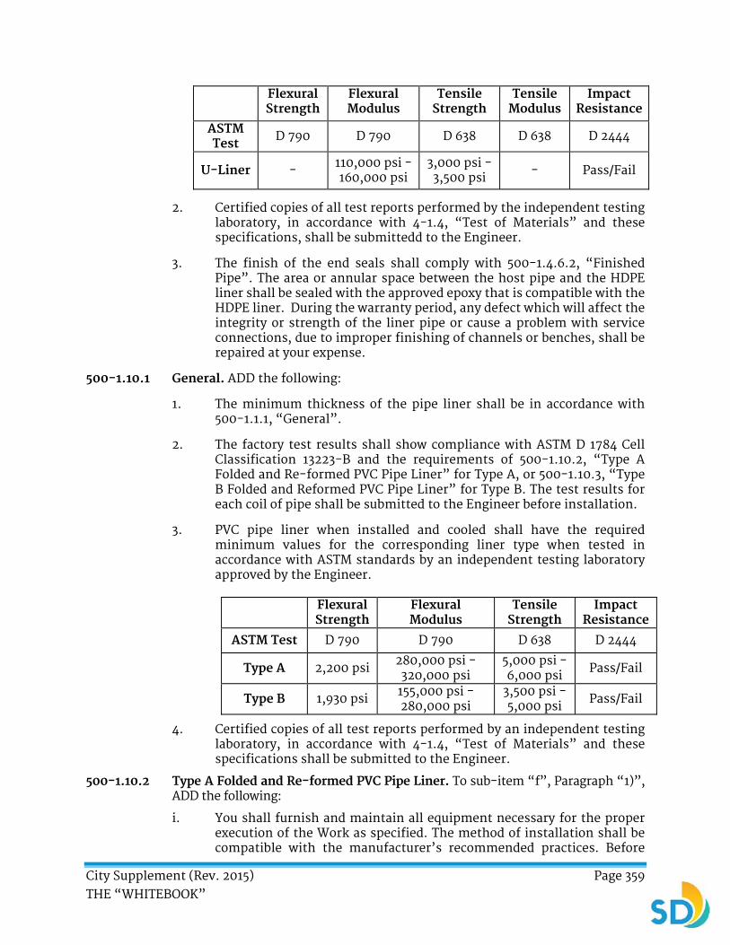
City Supplement (Rev. 2015) Page 359 THE “WHITEBOOK”
Flexural Strength
Flexural Modulus
Tensile Strength
Tensile Modulus
Impact Resistance
ASTM Test D 790 D 790 D 638 D 638 D 2444
U-Liner - 110,000 psi - 160,000 psi
3,000 psi - 3,500 psi - Pass/Fail
2. Certified copies of all test reports performed by the independent testing laboratory, in accordance with 4-1.4, “Test of Materials” and these specifications, shall be submittedd to the Engineer.
3. The finish of the end seals shall comply with 500-1.4.6.2, “Finished Pipe”. The area or annular space between the host pipe and the HDPE liner shall be sealed with the approved epoxy that is compatible with the HDPE liner. During the warranty period, any defect which will affect the integrity or strength of the liner pipe or cause a problem with service connections, due to improper finishing of channels or benches, shall be repaired at your expense.
500-1.10.1 General. ADD the following:
1. The minimum thickness of the pipe liner shall be in accordance with 500-1.1.1, “General”.
2. The factory test results shall show compliance with ASTM D 1784 Cell Classification 13223-B and the requirements of 500-1.10.2, “Type A Folded and Re-formed PVC Pipe Liner” for Type A, or 500-1.10.3, “Type B Folded and Reformed PVC Pipe Liner” for Type B. The test results for each coil of pipe shall be submitted to the Engineer before installation.
3. PVC pipe liner when installed and cooled shall have the required minimum values for the corresponding liner type when tested in accordance with ASTM standards by an independent testing laboratory approved by the Engineer.
Flexural Strength
Flexural Modulus
Tensile Strength
Impact Resistance
ASTM Test D 790 D 790 D 638 D 2444
Type A 2,200 psi 280,000 psi - 320,000 psi
5,000 psi - 6,000 psi Pass/Fail
Type B 1,930 psi 155,000 psi - 280,000 psi
3,500 psi - 5,000 psi Pass/Fail
4. Certified copies of all test reports performed by an independent testing laboratory, in accordance with 4-1.4, “Test of Materials” and these specifications shall be submitted to the Engineer.
500-1.10.2 Type A Folded and Re-formed PVC Pipe Liner. To sub-item “f”, Paragraph “1)”, ADD the following:
i. You shall furnish and maintain all equipment necessary for the proper execution of the Work as specified. The method of installation shall be compatible with the manufacturer’s recommended practices. Before

City Supplement (Rev. 2015) Page 360 THE “WHITEBOOK”
installation, the pipe coils shall be tested by you in accordance with ASTM D2122 to verify compliance with the minimum wall thickness.
ii. The liner pipe shall be inserted into the existing sewer through existing manholes, without modification of the manholes.
To sub-item “f”, Paragraph “6)”, ADD the following:
i. If the liner fails to form, you shall remove the failed liner and replace it with a new liner. This Work shall be performed without additional costs to the City. After the line has been formed, the ends of the liner shall be cut away at both manholes.
ii. The finished liner shall comply with 500-1.4.6.2, “Finished Pipe”. Any defect which will affect the integrity or strength of the liner pipe or cause a problem with the service connections, due to improper finishing of channels or benches, shall be repaired at your expense.
500-1.10.3 Type B Folded and Re-formed PVC Pipe Liner. To sub-item “f”, ADD the following:
7) You shall submit factory test results and the date the PVC liner was manufactured for each coil of pipe prior to installation for approval. No pipe liner shall be installed later than 6 months from date of manufacture.
8) You shall furnish and maintain all equipment necessary for the proper execution of the Work as specified. The method of installation shall be compatible with the manufacturer’s recommended practices. Before installation, the pipe coils shall be tested by you in accordance with ASTM D2122 to verify compliance with the minimum wall thickness.
500-1.13.1 General. ADD the following:
The lining process shall use a continuous PVC profile strip which is machine-wound directly into the existing pipeline from an existing manhole. The process shall be continued until the complete length of the existing pipe has been lined. PVC profile strip for machine spiral-wound liner pipe rehabilitation of existing sewers shall comply with ASTM F1697 except as modified herein.
500-1.13.6 Installation and Field Inspection. ADD the following:
1. Installation of machine spiral-wound PVC liner pipe rehabilitation of existing sewers shall comply with ASTM F1741 except as modified herein.
2. The existing pipeline shall be cleaned of any obstructions and televised in accordance with 500-1.1.4, “Cleaning and Preliminary Inspection” and 500-1.1.5, “Video Inspection”. Existing live service connections shall be precisely located longitudinally, radially, and in accordance with sub-item “a” of 500-1.1.7, “Miscellaneous” and 500-1.4.7, “Service Connections and End Seals” and logged for subsequent reinstatement following insertion of the PVC strip pipe liner.
City Supplement (Rev. 2015) Page 361 THE “WHITEBOOK”
3. Coincident with lining forming into a spiral by the winding machine, a bead of Vulkem 116 Urethane Caulk or equal shall be injected during the winding process into the double locking elements in a sufficient amount such that upon cure it will create a watertight seal as tested on a deflected segment of fully expanded pipe.
4. You shall submit for the Engineer’s approval the method and material composition for the end sealing and service lateral sealing material.
500-1.13.7 Connections. DELETE in its entirety and SUBSTITUTE with the following:
Service lateral reconnection shall be re-established and sealed in accordance with sub-item “a” of 500-1.1.7, “Miscellaneous” and 500-1.4.7, “Service Connections and End Seals”.
ADD:
500-2.4.6 Primer and Lining Materials.
1. The primer materials for the polyurethane lining material shall be 100% solids, moisture-tolerant epoxy capable of spray application to 5 mils (127 μm) thickness in one continuous coat.
2. The polyurethane lining material shall be 100% solids, high-build polyurethane capable of spray application to 125 mils (3175 μm) thickness in one continuous coat. The material shall meet the requirements of 210-2.3.3, “Chemical Resistance Test (Pickle Jar Test)” and 500-2.4.10, “Applicable Standards”. Proof of meeting these requirements shall be provided to the Engineer for approval at least 15 Days prior to commencement of Work.
3. The epoxy lining material shall be 100% solids, high-build epoxy capable of spray application to 125 mils (3175 μm) thickness in one continuous coat. The material shall meet the requirements of 210-2.3.3, “Chemical Resistance Test (Pickle Jar Test)” and 500-2.4.10, “Applicable Standards”. Proof of meeting these requirements shall be provided to the Engineer for approval at least 15 Days prior to commencement of Work.
ADD:
500-2.4.7 Lining Application. The polyurethane or epoxy lining application shall take place after the Air-Placed Concrete (APC) has cured for a minimum of 24 hours and shall be applied to all concrete surfaces from 3 mils (76 μm) below the low-flow water level to the base of the ring and cover. Prior to the polyurethane application, the manhole surfaces shall be primed with the epoxy primer to a thickness of 3 mils (76 μm) minimum to 5 mils (127 μm) maximum. Prior to the epoxy primer becoming tack-free, the polyurethane lining shall be immediately applied to a thickness of 100 mils (2540 μm) minimum to 125 mils (3175 μm) maximum. The epoxy lining shall be applied to a thickness of 100 mils (2540 μm) minimum to 125 mils (3175 μm) maximum. The finished polyurethane or epoxy lining shall be uniform in color, fully cured, and free of pinholes, surface imperfections, and blisters.
City Supplement (Rev. 2015) Page 362 THE “WHITEBOOK”
ADD:
500-2.4.8 Test.
1. The cured epoxy and polyurethane lining shall be subjected to adhesion (bond) testing. A minimum of three 20 mm (0.79 inch) dollies shall be fixed to the lined surface of each selected manhole as determined by the City and shall be pulled in accordance with ASTM D7234, utilizing an Elcometer 106 instrument. The failure shall be in the substrate concrete at no less than 300 psi. For any given lining failure, one additional manhole shall be added to the initial number of manholes to be tested. The City shall further evaluate any areas detected to have inadequate adhesion. Further adhesion testing may be performed to determine the extent of potentially deficient bonded area. Repairs shall be made in accordance with 500-2.4.9, “Repair Methods”.
2. The cured polyurethane lining shall be spark tested for pinholes, in the presence of the Engineer, with a spark tester set at 15,000 volts minimum. Pinholes shall be repaired in accordance with 500-2.4.9, “Repair Methods”. The cured epoxy lining shall be spark tested for pinholes with a spark tester initially set at 12,500 volts, or 100 volts per mil of film thickness, but may be adjusted as necessary to detect an induced holiday.
ADD:
500-2.4.9 Repair Methods. Defects in the APC shall be repaired in accordance with manufacturer’s instructions or 303-1.10, “Curing” and 200-1, “Rock Products”. Pinholes in the protective lining shall be marked off on surface areas containing pinholes to a point 6 inch (152.4 mm) beyond all pinholes and recoated with the epoxy lining or primed with epoxy primer and recoated with polyurethane to a minimum additional thickness of 30 mils (762 μm). Blisters, uncured lining, and surface imperfections shall be completely removed and the areas recoated with the epoxy lining or epoxy primer and polyurethane lining to a point 6 inch (152.4 mm) beyond the repair areas at a minimum thickness of 100 mils (2540 μm).
ADD:
500-2.4.10 Applicable Standards. APC, epoxy primer, and polyurethane or epoxy lining shall meet or exceed the requirements specified with manufacturer’s instructions or 303-1.10, “Curing” and Table 500-2.4.10. Test results shall be verified on a per job basis or as required by the Engineer.

City Supplement (Rev. 2015) Page 363 THE “WHITEBOOK”
TABLE 500-2.4.10
Polyurethane Epoxy Primer Epoxy Tensile Strength 13.8 41.4 51.7 ASTM D638, Type IV, MPa (psi) (2,000) (6,000) (7,500) Elongation at Break, % ASTM D638, Type IV 50 5 1.5 The Wear Resistance, mg. wt. loss Taber abrasion, S-17 ASTM D4060 60 100 115 Hardness, Shore D, Durometer ASTM D2240 55 75 85 Tear Resistance, kg/mm (ppi) 2.7 ASTM D624 (150) N/A N/A Peel Strength, Concrete, g/mm (pli) 125 125 N/A ASTM D903 (7)1 (7)1 N/A Adhesive Strength, kPa (psi) 2,760 2,760 N/A ASTM C307 (modified) Briquet, PCC (400)1 (400)1 N/A ASTM D7234 Method D, Concrete, mode of failure concrete concrete concrete
1. Tested as a system.
ADD:
500-2.11 CURED-IN-PLACE MANHOLE (CIPM) LINER.
500-2.11.1 General. CIPM liner for the rehabilitation of a manhole shall include the furnishing of all labor, materials, and equipment for the rehabilitation of an existing manhole with the installation of tailored fabric liner system covering the inside surface of manhole wall and shelf. The fabric shall be impregnated with epoxy resin and placed tight against the manhole wall and shelf and cured with pressurized steam.
500-2.11.2 Material Composition and Testing. The fabric liner shall contain a PVC membrane and one or more layers of polyester fleece and fiberglass reinforcement. The material shall be compatible with and capable of carrying epoxy or epoxy-vinyl-ester resin, be able to withstand installation pressure and curing temperature between 160° F and 200 °F (71.1 °C and 93.3 °C). The approved epoxy shall be compatible with the application and be able to cure in the presence of hot steam. The initiation temperature for cure shall be as recommended by the resin manufacturer and approved by the Engineer. The CIPM liner shall comply with ASTM D695, ASTM D790, and ASTM C857 and shall have, as minimum, the structural properties in accordance with Table 500-1.4.2. You shall provide Field-cured samples as directed by the Engineer.
500-2.11.3 Resin and Fabric Acceptance.
1. Resin and fabric shall comply with 500-1.4.3, “Resin and Tube Acceptance”. The fabric shall be custom tailored to fit any shape manhole wall including base, cone, and risers. The fabric shall be tailored such that, after curing, the maximum allowed pliable wrinkles do not exceed ½ inch (12.7 mm) ply. Excessive wrinkles or plies may be grounds for rejecting the

City Supplement (Rev. 2015) Page 364 THE “WHITEBOOK”
rehab Work. You shall assure maximum resin coverage where plies are anticipated.
2. The minimum design thickness of the fabric shall be 20 mils PVC membrane, 10 oz/yd2 of polyester fleece backing, and 18 oz/yd2 of fiberglass backing. The minimum total composite thickness shall be 88 mils.
3. The fabric shall be completely submerged in resin to allow for maximum absorption. Resin containment shall be your responsibility.
500-2.11.4 Chemical Resistance. The CIPM liner system shall comply with 500-1.4.4, “Chemical Resistance”.
500-2.11.5 Installation.
1. Prior to placing the liner, the manhole shall be cleaned in accordance with 500-2.4.2, “Spark Test”. You shall repair spalled or deteriorated concrete in accordance with 500-2.4.3, “Mill Gauge Test”, 500-2.4.4, “Adhesion Testing”, and 500-2.4.5, “Liner Repairs”.
2. Installation shall be by an installer that is qualified by the liner manufacturer. You shall include the furnishing of all materials, equipment, tools, and labor as required for the rehabilitation of the manholes selected, including the installation of the interior liner. The installation of the approved liner system shall be in strict accordance with the manufacturer’s instructions. This shall include the preparation, installation, inflation, curing, and finishing operation required for the completion of the manhole rehabilitation process. Safety rules and regulations applicable laws and insurance requirements shall be observed in storing, handling, use and application of the liner materials, resins, and any solvents. Ventilation shall be provided to the workers at all times.
3. The liner shall be installed and cured in place via controlled curing by heat and pressurization (2 psi to 5 psi) in the manhole to complete the curing process in less than 2 hours.
4. The lining of the manhole shall result in a monolithic structure to the shape and contour of the existing manhole. The liner shall be installed and bond to the interior manhole substrate and completely watertight, free of any joints or openings.
500-2.11.6 Payment. The payment for the rehabilitation of the manhole shall be made at the vertical foot Bid item price for “Rehabilitate Existing Manhole with Cured-In-Place Manhole Liner” and shall include all necessary labor, material, and equipment to clean, repair, and line the manhole as specified herein. The vertical foot liner measurement is defined as the distance between the top of shelf to the manhole cover seat.
500-4 SERVICE LATERAL CONNECTION SEALING. DELETE in its entirety and SUBSTITUTE with the following:
500-4 SERVICE LATERAL CONNECTION (SLC) SEALING.
500-4.1 General.
1. Service Lateral Connection is the interface of the house sewer lateral with the main sewer. SLC to rehabilitated sanitary sewer lines shall be

City Supplement (Rev. 2015) Page 365 THE “WHITEBOOK”
sealed, normally without excavation, by the installation of a resin-impregnated, flexible, felt tube or fiberglass tube installed into the existing service lateral. The tube shall form a “tee” section with a full lap inside the main pipe and shall extend continuously from the sewer main into the lateral for a minimum of 4 inch (101.6 mm). SLC may be a combination of “tees” or “wyes” of varying angle. The resin shall be cured to form the tube into a hard impermeable pipe-within-a-pipe. When cured, the SLC sealing shall seal the connection of the lateral to the mainline in a continuous tight-fitting, watertight pipe-within-a-pipe to eliminate any visible leakage between the lateral and mainline and shall provide a leak-proof seal designed for a minimum 50-year life to prevent root intrusion, infiltration, and exfiltration between a liner and a host pipe.
2. Prior to cleaning, you shall submit a detailed operational plan for the proposed cleaning of all roots inside the pipe and around the service connection for the Engineer’s approval. After cleaning, you shall proceed with lining of the pipe and reinstating all live service connections. The service connection openings shall conform to the shape and the size of the inside diameter of the existing service connection. You shall use a wire brush or other methods and equipment as recommended by other lining system providers or other approved means and methods to provide a smooth opening for connecting the lateral to the newly lined pipeline.
3. You shall trim all protruding laterals which interfere with the lining installation as flush with the pipe interior as practicable.
500-4.2 Reference Specification. This specification references ASTM test methods which are made a part hereof by such reference and shall be the latest edition and revision thereof and shall meet the chemical resistance requirements of 210-2.3.3, “Chemical Resistance Test (Pickle Jar Test)”.
500-4.3 General Corrosion Requirements.
1. The finished SLC sealing product shall be fabricated from materials which when cured shall be chemically resistant to withstand internal exposure to domestic sewage and shall meet the chemical resistance requirements of 210-2.3.3, “Chemical Resistance Test (Pickle Jar Test)” and Table 210-2.4.1.
2. The SLC sealing product shall be compatible with the lining system materials utilized in the main sewer line.
500-4.4 SLC Materials.
1. A flexible felt tube shall be fabricated to neatly fit the internal circumference of the conduit specified by the City. Allowance shall be made for circumferential stretching during insertion.
2. The SLC sealing shall extend a minimum of 4 inches (101.6 mm) from the mainline into the lateral.
3. You shall furnish a specially designed, unsaturated polyester or vinyl ester resin and catalyst system compatible with the SLC sealing process that provides cured physical strengths specified herein.

City Supplement (Rev. 2015) Page 366 THE “WHITEBOOK”
500-4.5 Physical Properties.
1. The cured SLC sealing shall conform to the minimum structural standards as listed in Table 500-1.4.2.
2. No cured-in-place pipe rehabilitation technology shall be allowed that requires bonding to the existing pipe for any part of its structural strength.
3. Design methods are to be derived for various loading parameters and modes of failure. Equations shall be modified to include deformation in the shape of an oval as a design parameter. The design method shall be submitted to the Engineer for approval prior to the Pre-construction Meeting.
500-4.6 Installation Preparation.
1. You shall remove internal debris out of the sewer line.
2. Inspection of pipelines shall be performed by experienced personnel trained in locating breaks and obstacles by closed circuit television. The interior of the pipeline shall be carefully inspected to determine the location of any conditions which may prevent proper installation of the SLC sealing into the pipelines and it shall be noted so that these conditions can be corrected. A color video and suitable log shall be kept for later reference by the City.
3. When required, provide for the flow of sewage around the section or sections of mainline pipe where the service lateral designated for SLC sealing is located. The bypass shall be made by plugging the line at an existing upstream manhole and pumping the flow into a downstream manhole or adjacent system. The pump and bypass lines shall be of adequate capacity and size to handle the flow without service interruption. The bypass systems shall be approved in advance by the City.
4. The service lateral shall be inactive during the time of installation.
5. You shall clear the line of obstructions that prevent the insertion of the SLC sealing material. If inspection reveals an obstruction that cannot be removed by conventional sewer cleaning equipment, you shall make an external point repair excavation to uncover and remove the obstruction. You shall inform the Engineer prior to the commencement of the Work.
6. The mainline pipe opening shall be prepared to accept the SLC sealing and the mainline rehabilitated pipe shall be maximized to obtain the best possible connection.
7. The transition from the mainline pipe to the service lateral shall be smooth and continuous to provide adequate support for the SLC sealing during installation and cure.
500-4.7 SLC Sealing Installation.
1. The resin impregnated tube shall be loaded inside a pressure apparatus. The pressure apparatus, attached to a robotic device, shall be positioned in the mainline pipe at the service connection. The robotic device, together with a television camera, shall be used to align the SLC repair with the service connection opening. Air pressure, supplied to the
City Supplement (Rev. 2015) Page 367 THE “WHITEBOOK”
pressure apparatus through an air hose, shall be used to invert the resin impregnated SLC sealing into the lateral pipe. The inversion pressure shall be adjusted to fully invert the SLC sealing into the lateral pipe and hold the tube tight to the pipe wall. Care shall be taken during the curing process not to over-stress the tube.
2. The pressure apparatus shall include a bladder which shall inflate in the mainline pipe, effectively seating the SLC repair against the service connection.
3. After inversion or pull-in is completed, the recommended pressure shall be maintained on the impregnated tube for the duration of the curing process. Curing method shall be compatible with the resin selected. An ultraviolet (UV) light cured, heat cured, or ambient cured resin system is typically used.
4. The initial cure shall be deemed to be completed when the SLC sealing has been exposed to the UV light or heat source or held in place for the time period specified by the manufacturer.
5. You shall cool the hardened SLC sealing before relieving the pressure in the pressure apparatus. Cool-down may be accomplished by the introduction of cool air into the pressure apparatus. Care shall be taken to maintain proper pressure throughout the cure and cool-down period.
6. The finished SLC shall be free of dry spots, lifts, and delamination. The lateral SLC shall not inhibit the final video of the mainline or service lateral pipes. Frayed ends of the SLC repair shall be removed prior to acceptance.
7. During the warranty period, any defects which shall affect the integrity of strength of the SLC shall be repaired at your expense in a manner mutually agreed upon by the manufacturer, City, and you.
8. After the Work is completed, you shall provide the City with a video recording showing the completed Work including the restored conditions.
500-4.8 Clean-Up. Upon acceptance of the installation Work, you shall reinstate the Site affected by its operations.
500-4.9 Payment. The payment for Service Lateral Connection Work shall be made at the Contract Unit Price or lump sum price in the Bid for each Service Lateral Connection. The Contract Unit Price or lump sum price in the Bid shall include the furnishing and the installation of the Service Lateral Connection sealing system, surface preparation and repairs, preparation and tape submittal of all post cleaning videos and final videos, bypassing if required, and testing, unless otherwise specified in the Special Provisions.
******** END OF PART 5 ********

City Supplement (Rev. 2015) Page 368 THE “WHITEBOOK”
PART 6
TEMPORARY TRAFFIC CONTROL
SECTION 600 – ACCESS
DELETE in its entirety and SUBSTITUTE with the following:
SECTION 600 – ACCESS
600-1 GENERAL. Your Work shall cause no unnecessary inconvenience to the public or businesses in the vicinity of the Work. You shall have no greater length or quantity of Work under construction than can be prosecuted with a minimum of inconvenience to the public and other contractors engaged in adjacent or related Work. You shall notify property owners and tenants in accordance with 7-16.2, “Community Outreach Services”. Post signs notifying the public a minimum of 5 Working Days prior to closure or detour of streets.
You shall provide continuous and unobstructed vehicular and pedestrian access to the adjacent properties unless otherwise specified in the Special Provisions, Traffic Control Plans, or Traffic Control Permit as approved by the City.
1. You shall verify waste collection schedules via the Environmental Services website at:
http://www.sandiego.gov/environmental-services/collection/index.shtml
2. You shall cooperate with the various parties involved in the delivery of mail and the collection of trash, recycling, and yard waste to maintain existing schedules for these services.
3. You shall comply with the following requirements for trash, recycling, and yard waste collection:
a) Provide advance written notice to every property affected by blocked public right of way.
b) Coordinate the relocation of trash, recycling, and yard waste containers to an accessible public street for the City’s waste collection crews on collection day.
c) When necessary, relocate the containers from the blocked streets to the accessible public right of way before the City’s collection vehicles arrive to assist with collection on existing schedules. Return the containers to their point of origin to ensure the accuracy of inventory assignment by address.
4. You shall notify Environmental Services Department via fax (858-526-2356) of street closures affecting the regular scheduled solid waste collection at least 3 Working Days prior to the street closure. Include your business name

City Supplement (Rev. 2015) Page 369 THE “WHITEBOOK”
and phone number, Day(s) of closure, time of scheduled closure, and date of anticipated street reopening in the notification.
5. If the City’s crews are unable to provide the citizens with the mandated services due to your failure to comply with these specifications, you shall collect trash, recyclables, and yard waste on the City’s schedule and deliver to the City’s designated locations or arrange to have a private franchise hauler provide the collection service at your expense.
6. The term “Railroad” means an owner, operator, inhabitant or controller of rail facilities. These include San Diego Metropolitan Transit System (MTS), San Diego Trolley, Inc. (SDTI), San Diego Association of Governments (SANDAG), Port of San Diego, San Diego & Arizona Eastern Railroad (SD&AE), American Track - National Railroad Passenger Corporation (AMTRACK), Transit America, Union Pacific Rail Road Company (UPRR), Burlington Northern Santa Fe Railway (BNSF), and North County Transit District (NCTD).
7. You shall obtain a Right of Entry Permit from Railroad prior to entering or constructing on property owned, operated, occupied, or controlled by the Railroad. You shall abide by the terms of the Right of Entry Permit and shall arrange and pay for inspection as required by the Railroad. The terms of the Right of Entry Permit control over the Plans and Specifications. Your right to enter right-of-way owned, operated, occupied, or controlled by Railroad is subject to the absolute right of Railroad to cause your Work to cease if, in the opinion of Railroad, your activities create a hazard to Railroad’s patrons, employees, and operations.
8. Information on obtaining a Right of Entry Permit and regarding policies can be obtained at:
MTS Right of Way Services at 619-557-4501 or http://www.sdmts. com/Business/Permits.asp
NCTD Customer Service at (760) 996-6500 or http://www.gonctd.com/working-around-the-rails
BNSF Permit Management Office (817) 230-2628 http://www.bnsf.com/communities/faqs/permits-real-estate/ - permit
UPRR Customer Service at (402) 501-4941 or http://www.up.com/real_estate/tempuse/index.htm
9. If Work is located within the flight path of aircrafts landing or taking off at San Diego airports, you shall obtain a construction permit for tall equipment (such as cranes) through Federal Aviation Administration (FAA).
10. Where Work occurs on Harbor Drive or impacts traffic flow to San Diego International Airport (Airport) from adjacent and contiguous streets such as Pacific Highway, Laurel Street, Grape Street, Hawthorn Street, and

City Supplement (Rev. 2015) Page 370 THE “WHITEBOOK”
Nimitz Blvd., adjust the Schedule to take advantage of the reduced Airport operations and low vehicular traffic on Harbor Drive and surrounding streets between the hours of 11:00 PM and 5:00 AM, Monday through Saturday, or as stipulated by your Traffic Control Permit. Do not interrupt access to the Airport.
11. Notify and coordinate with Metropolitan Transit System (MTS) and the San Diego County Regional Airport Authority (Airport Authority) a minimum of 5 Working Days prior to excavation, construction, or temporary traffic control affecting airport operation and transit stops. Notify the remaining agencies a minimum of 2 Working Days prior to construction activities affecting the agencies:
Fire Department Dispatch (Street or alley closure) (858) 573-1300
Police Department Traffic (Street or alley closure) (858) 495-7800
Street Division/Electrical (Traffic signals) (619) 527-7500
U.S. Navy (32nd Street Naval Station) (619) 556-1319
Underground Service Alert (Any excavation) (800) 422-4133
MTS (Street Closure and Bus Stops) (619) 238-0100 Ext 6451
San Diego County Regional Airport Authority (619)-400-2880
12. If weather condition is suitable, complete each street segment within 15 Working Days from the day of the resurfacing. Each completed segment shall include other incidental Work items such as weed abatement, damaged asphalt pavement replacement, asphalt patching, striping, markings, raised pavement markers, traffic signal detectors, and inlet markers.
600-2 VEHICULAR ACCESS. Vehicular access to private properties and businesses shall be maintained to the property line except when necessary construction precludes such access. Maintain cross traffic and turning moves at the intersections. If backfill has been completed to the extent that safe access may be provided and the street is opened to local traffic, you shall immediately clear the street and driveways and provide and maintain access. Maintain full width of all traffic lanes of the existing roadway during non-working hours and on Saturday, Sunday, designated Holidays, and when construction operations are not actively in progress on Working Days.
600-3 PEDESTRIAN ACCESS. See CA MUTCD Chapter 6D for requirements and guidelines.
Pedestrian zones and public transportation stops, as well as pedestrian crossings of the Work site at intervals not exceeding 300 foot (91.4 m) shall be maintained unless otherwise approved by the Engineer. When sidewalks are closed, an alternate walkway shall be provided. Pedestrians shall not be directed into direct conflict with vehicles operating within the Work site or other traffic. Where it is necessary to divert pedestrians into the parking lane or a street, barricades or temporary traffic barriers shall be provided to separate the pedestrian walkway from the adjacent traffic lane.

City Supplement (Rev. 2015) Page 371 THE “WHITEBOOK”
If crosswalk closures are necessary, you shall close only one crosswalk at a time at intersections having 4 crosswalks. If 2 or more crosswalk closures at an intersection are necessary, you shall submit a pedestrian detour plan and obtain approval from the Engineer before implementation of the closure. Approval from the Engineer shall be obtained before closing any crosswalks at intersections having fewer than 4 crosswalks.
Vertical changes of surface elevations in areas subject to pedestrian traffic of 1/2 inch (12.5 mm) or greater shall have a beveled edge of 12 horizontal to 1 vertical.
Walkways within the Work site shall be a minimum of 4 foot (1.2 m) in width and 6 foot (1.8 m) in width in high volume pedestrian area with passing spaces at least 60 inches (1524 mm) by 60 inches (1524 mm) every 200 feet (61.0 m). Obstructions within walkways shall be illuminated during hours of darkness. The minimum vertical clearance to any obstruction larger than 4 inches (101.6 mm) within a walkway shall be 7 feet (2.1 m).
The minimum horizontal clearance (buffer space) between walkways within the Work site and Work areas or operating equipment shall be a minimum of 5 feet (1.5 m).
600-3.1 ADA Requirements. Temporary facilities shall be detectable by a person with a visual disability traveling with the aid of a long cane and include accessibility features consistent with the features present in the existing pedestrian facility. A detectable barrier shall be placed across the full width of the closed sidewalk. Channelized pedestrian routs shall be clear of obstacles and shall have a continuous detectable edging.
The accessible route shall have the following:
1. Clear headroom of at least 80 inches (2032 mm).
2. A surface that is firm, stable, and slip resistant.
3. No level changes in excess of 1/2 inch (12.5 mm) vertically (in the absence of a curb ramp, ramp, elevator, or platform lift).
4. A curb ramp slope of less than 8.3% (1:12).
5. A path of travel slope of less than 5% (1:20) and a cross slope of less than 2% (1:50).
6. Routes that are under scaffolding conforming to ADA requirements.
7. Audible information devices (when shown on Plans or Traffic Control Permit).
600-4 BICYCLE ACCESS. Bikeway systems interrupted by Temporary Traffic Control (TTC) shall have signage through or around the TTC back to the bikeway in accordance with 601, “TEMPORARY TRAFFIC CONTROL FOR CONSTRUCTION AND MAINTENANCE WORK ZONES”. Roadways adjacent to the Work site shall be kept free of obstructions or other hazards to bicyclists.
600-5 PAYMENT. Payment for access as specified in 600, “ACCESS”, the railroad liability insurance, permits, plan review, inspection, flagging, and fees shall be
included in the Contract Price unless Bid items have been provided.NTROL

City Supplement (Rev. 2015) Page 372 THE “WHITEBOOK”
DELETE in entirety and SUBSTITUTE with the following:
SECTION 601 – TEMPORARY TRAFFIC CONTROL FOR CONSTRUCTION AND MAINTENANCE WORK ZONES
601-1 GENERAL. Temporary traffic control (TTC) for construction and Work zones shall conform to Part 6 of the California MUTCD, the Specifications, and the Traffic Control Plan (TCP) if so included with the Plans or if required to be prepared by you and submitted as a Working Drawing.
1. Working hours are the Normal Working Hours unless otherwise specified. Work requiring traffic lane closures shall only be performed between the hours specified in the Special provisions or shown on the TCP.
2. Traffic shall be permitted to pass though the Work site, unless otherwise specified in the Special Provisions or shown on the TCP.
3. If construction is to be performed in phases, complete the Work in each phase prior to beginning the Work in the next phase. Approval of temporary Traffic Control Plans or Working Drawings for hours outside of the Normal Working Hours does not constitute a guarantee that the Engineer will be available to inspect the Work.
4. TTC activities and milestones shall be shown as activities on your construction schedule in accordance with 6-1, “CONSTRUCTION SCHEDULE AND COMMENCEMENT OF THE WORK”.
5. The term “hours of darkness” used in the Specifications shall mean the hours of darkness as defined in Division 1, Section 280, of the California Vehicle Code.
6. Roadways adjacent to the Work site shall be kept clean and free of obstructions or other hazards. Do not store or allow equipment, material, or debris to remain in the public right-of-way without prior approval by the Engineer.
7. You shall conduct roadway construction operations in a manner that provides a surface safe for vehicular traffic. Vertical changes of pavement elevations 1½ inches (37.5 mm) or greater shall have a beveled edge of 4 horizontal to 1 vertical.
8. Pavement surface disruptions in marked bike lanes or routes of ½ inch (12.5 mm) or more shall have a beveled edge of 8 horizontal to 1 vertical. Signs indicating the condition of the surface of the pavement shall be posted as shown on the TCP or as specified in the Special Provisions. If the pavement surface elevation changes are not beveled and signs are not posted, the bicycle lane or route shall be closed.
9. When a bicycle lane or route is closed, signing shall be installed to terminate the bike lane or route. Signs shall be posted to advise

City Supplement (Rev. 2015) Page 373 THE “WHITEBOOK”
motorists and bicyclists that the previously separated bicycle traffic will be in the vehicular traveled way. Barricades used at the terminus or the closure shall be spaced to prevent physical passage by bicyclists into the closed bicycle lane or route.
10. Lane restrictions, flagging, or other operations shall not cause traffic to stop on railroad tracks. Whenever the Work causes traffic to back up across an active railroad track, a flagger shall be provided.
11. Backfill or cover trenches with steel trench plates at the end of each Work day. “STEEL PLATE AHEAD” (W8-24) signs should be present whenever steel plates are present. Place an asphalt ramp around each trench plate. Upon completion of excavation backfill, provide a satisfactory surface for traffic. Portable concrete barriers, additional noticing, and other items may be required when trenching cannot be secured overnight by backfilling or trench-plating.
12. You shall furnish, install, program, and maintain a City approved temporary video or radar detection system to provide vehicle detection for intersection approaches that existing detection systems are damaged, disabled, or become ineffective due to construction activities for a period of 5 or more Days. At the completion of the construction phase, you shall be responsible for the complete removal of all temporary detection equipment and restorations or installation of the permanent vehicle detection system.
13. Additional TTC requirements shall be as specified in the Special Provisions.
601-2 TRAFFIC CONTROL PLAN (TCP).
601-2.1 General. If specified in the Contract Documents, you shall submit a TCP in accordance with 2-5.3, “Submittals”.
Traffic Control Plans shall have the project title, phase identification, name of the firm preparing the TCP, name and stamp of the Registered Civil Engineer, approval block for each jurisdictional agency, north arrow, sheet number, and number of sheets comprising the TCP. General notes and symbol definitions shall be included when required.
The TCP shall be drawn to a 1 inch = 40 feet (1:500) scale on common size sheets, either 8½ inches (215.9 mm) x 11 inches (279.4 mm), 8½ inches (215.9 mm) x 14 inches (355.6 mm), 11 inches (279.4 mm) x 17 inches (431.8 mm), or 2 feet (609.6 mm) x 3 feet (914.4 mm) Plan sheets as dictated by the length of Work.
The requirements in the Special Provisions shall govern the design of the proposed TCP. Working Drawings may be approved by the Engineer.
1. The TCP shall clearly show all necessary details. The TCP shall be Site-specific. The Engineer will not accept typical Plans and sections.
2. Prepare TCP in accordance with the City’s Computer Aided Design and Drafting (CADD) standards. You may use any standard engineering CADD program (MicroStation or AutoCAD) to prepare the TCP.
3. Allow at least 20 Working Days for the Engineer’s review of each submitted TCP.

City Supplement (Rev. 2015) Page 374 THE “WHITEBOOK”
601-2.1.1 Traffic Control Permit.
1. Do not begin the Work in the public roadway without the approved temporary traffic control permit. The TCP are not valid until Work dates are approved and a temporary traffic control permit is issued by the City.
2. For City Projects, coordinate the traffic control permit application submittal with the Work so that no items of Work will be delayed. To obtain a temporary traffic control permit, call the Construction Management and Field Services Division (CMFS), Traffic Control Section, (858) 495-4741 for an appointment a minimum of 2 Working Days prior to starting the Work (5 Working Days when the Work will affect a traffic signal). Provide 1 copy of the temporary traffic control drawings specified in the Contract Documents at the time of the appointment. Upon approval of your TCP, the Traffic Control Section of the CMFS Division will issue the permit.
3. For Private Development Projects, the Developer/Contractor shall submit a Traffic Control Plan (TCP) to Development Services Department for approval prior to starting Work. The Developer/Contractor shall also obtain a Temporary Traffic Control Permit for the approved TCP from Development Services Department for any Work in the public right-of-way prior to start of Work. Temporary Traffic Control Permit can be obtained at the traffic control permit counter, 3rd floor, booth 22, Development Services Center, 1222 First Avenue, San Diego (619-446-5150). The Developer/Contractor shall obtain a Temporary Traffic Control Permit a minimum of 2 Working Days prior to starting Work, and a minimum of 5 Days if Work will affect a bus stop or an existing traffic signal or if Work will require a road or alley closure.
4. Submit proposed changes and deviations from the traffic control plan permit for the Engineer’s approval. Prior to implementation, the Engineer will observe the implementation of Traffic Control Plans and reserves the right to require you to make changes as field conditions warrant. The Engineer may approve the changes to the Traffic Control Plan Permit or if directed in writing by the Engineer.
5. Any Work impacting traffic to and from the San Diego International Airport shall be coordinated with the San Diego County Regional Airport Authority and Working Hours shall be approved by the San Diego County Regional Airport Authority prior to obtaining a Traffic Control Permit from the City.
601-2.1.2 Engineered Traffic Control Plans (TCP).
1. Engineered TCP shall be 2 feet (609.6 mm) x 3 feet (914.4 mm) sheets sized in accordance with 601-2, “General”. The engineered TCP shall be signed and stamped by a Professional Civil Engineer registered in the State of California (per CA MUTCD 1A.09).
2. Coordinate with the City’s Traffic Control Section of CMFS for the development and approval of the engineered TCP. Submit a Traffic Control Approach to the Engineer prior to preparing the engineered TCP. A list of traffic control items is available upon request from the CMFS
City Supplement (Rev. 2015) Page 375 THE “WHITEBOOK”
Division as a guideline. Prepare the engineered TCP in accordance with the approved Traffic Control Approach. You may obtain a copy of the Project area base map through the Engineer. If extensive additions or corrections are required, the CMFS Traffic Control Section will return the marked-up print for corrections and re-submission.
3. If no changes or corrections are required, the CMFS Traffic Control Section will retain the original engineered TCP and return 1 copy with the TCP Permit to you.
4. You are not entitled to Contract Time extensions if you fail to properly produce the engineered TCP and to schedule the Work.
5. You shall obtain or require your Subcontractor to obtain Architects and Engineers Professional Insurance in accordance with 7-3.10, “Architects and Engineers Professional Insurance (Errors and Omissions Insurance)” for the Work including your engineered 2 feet (609.6 mm) x 3 feet (914.4 mm) size engineered TCP.
601-2.1.3 Traffic Control Working Drawings. For those portions of the Work where Engineered TCP are not provided nor required, prepare and submit traffic control Working Drawings as part of your Traffic Control Permit package.
1. If extensive additions or corrections are required, the CMFS Traffic Control Section will return the marked-up print for corrections and re-submission.
2. If no change or correction is required, the original Working Drawings will be retained by the Engineer. One copy, with the TCP Permit attached, will be returned to you.
3. No extension of time will be allowed as a result of your failure to properly produce traffic control Working Drawings and to schedule the Work.
4. When required by the Engineer, Traffic Control Working Drawings shall be prepared and stamped by a Professional Civil Engineer.
601-2.1.4 Traffic Control for Resurfacing and Slurry Sealing.
1. Prepare TCP for Resurfacing and Slurry Sealing in accordance with 601-2.1.3, “Traffic Control Working Drawings”.
2. Place temporary reflective pavement markers on all roadways with painted centerline immediately upon completion of the resurfacing or slurry sealing. Remove temporary reflective pavement markers only for new permanent pavement striping.
3. The City will provide you, at the Pre-Construction Meeting, with the standard format for “NO PARKING - TOW-AWAY ZONE” signs for the resurfacing or slurry seal portion of the Work. Furnish the “NO PARKING - TOW-AWAY ZONE” signs and pedestals for posting on sidewalks and streets. Mount the “NO PARKING - TOW-AWAY ZONE” signs on suitable pedestals, such as tripods and barricades. Post signs every 50 feet (15.2 m) on both sides of the block affected by the proposed resurfacing, slurry sealing, or both.
City Supplement (Rev. 2015) Page 376 THE “WHITEBOOK”
4. Affix to each “NO PARKING - TOW-AWAY ZONE” sign cards with 2-inch (50.8 mm) high letters stating the day(s) of the week parking is prohibited, as well as your company name and telephone number. Remove the “NO PARKING - TOW-AWAY ZONE” signs immediately following the completion of the resurfacing, slurry sealing, or both.
5. For each street block segment scheduled for slurry sealing or resurfacing, the posted parking prohibition shall be for 2 consecutive Working Days. Schedule the slurry sealing on the first posted Working Day, unless approved by the Engineer. The second posted Working Day shall be reserved for emergency Work, and may be used only with the approval of the Engineer. Reschedule street block segments which are not completed by the second posted Working Day.
6. Place “NO PARKING - TOW-AWAY ZONE” signs no less than 48 hours in advance and no more than 72 hours in advance of the scheduled slurry sealing. Reschedule street block segments which are not completed by the last posted Working Day. If a Work delay of 48 hours or more occurs from the originally scheduled Work date, remove the “NO PARKING - TOW-AWAY ZONE” signs for a minimum of 24 hours, then reset and re-post for the appropriate Work date.
7. Furnish and distribute door hanger notices in sufficient quantities to advise the general public of the scheduled parking prohibitions in accordance with 7-16.2, “Community Outreach Services”.
601-2.1.5 Traffic Control for Street Closures and Detours.
1. You shall comply with all applicable State, County, and City requirements for the closure of streets.
2. Street closures, detours, barricades lights, other safety devices shall conform to current requirements covering “signs” as set forth by Caltrans.
3. You shall provide barriers, guards, lights, signs, temporary bridges, flag persons, and watch persons. You shall be responsible for complying with additional public safety requirements which may arise. You shall furnish and install signs and warning devices and promptly remove them upon completion of the Work.
4. At least 48 hours in advance of closing, partially closing or reopening, any street, alley, or other public thoroughfare, you shall notify the Police, Fire, Traffic and Engineering Departments, and comply with their requirements. Deviations shall first be approved in writing by the Engineer.
5. You shall secure approval, in advance, from authorities concerned for the use of any bridges proposed by it for public use. Temporary bridges shall be clearly posted as to load limit, with signs and posting conforming to current requirements covering “signs” as set forth in the Traffic Manual published by the California Department of Transportation. This manual shall also apply to the street closures, barricades, detours, lights, and other safety devices required.

City Supplement (Rev. 2015) Page 377 THE “WHITEBOOK”
6. Maintain, whether shown on the Plan or not, existing traffic control signs or signals in their proper location on temporary mounting supports until permanent signs or signals are restored.
7. When constructing a new roadway, install and maintain Type 3 barricades with flashing yellow lights and “Road Closed” signs, chain link fences, or both until the new or improved roadway is accepted by the Engineer.
8. For the Work in the vicinity of the Airport as specified in 600-1, “General”, perform the following:
a) Perform the Work necessitating closure of 1 or 2 more lanes on Harbor Drive outside Normal Working Hours unless otherwise specified in the Contract Documents.
b) When sufficient width is available, maintain a minimum of 2 travel lanes in each direction at all times unless otherwise specified in the Contract Documents or agreed upon by Airport representative(s).
c) Construct and maintain detours at the proper time. The Engineer will close down the Work if you fail or refuse to construct and maintain detours as required.
d) Do not interrupt the operation of the existing traffic signals and lighting unless otherwise specified.
e) Whenever a portion of the roadway is completed, make that section of the road available to traffic immediately if it does not conflict with the rest of the traffic control devises and if it does not compromise public safety.
f) Furnish flag persons, when required, to give adequate warning to traffic or to the public of any dangerous conditions to be encountered.
601-3 TEMPORARY TRAFFIC CONTROL (TTC) ZONE DEVICES.
601-3.1 General. TTC zone devices shall conform to NCHRP Report 350 criteria for TTC crashworthy devices and the California MUTCD. Retro-reflective sheeting used on TTC devices shall conform to ASTM D4956.
1. Furnish, install, and maintain the traffic control devices as shown on the traffic control permit and approved TCP’s and any additional traffic control devices as may be required to ensure the safe movement of vehicles and pedestrians and to provide for the safety of construction workers.
2. Maintain existing traffic control signs and traffic signals in their proper location on temporary mounting supports until permanent signs or signals are restored.
3. Your name or the Supplier’s name who owns the traffic control devices shall be clearly noted on each device.
601-3.2 Categories.

City Supplement (Rev. 2015) Page 378 THE “WHITEBOOK”
601-3.2.1 Category 1. Category 1 TTC zone devices shall be defined as small, lightweight devices weighing less than 100 pounds (45.4 Kg) certified as crashworthy by crash testing or crash testing of similar devices. Category 1 temporary traffic control zone devices include, but are not limited to, traffic cones, plastic traffic drums, portable delineators, and channelizers.
601-3.2.2 Category 2. Category 2 TTC zone devices shall be defined as small, lightweight devices weighing less than 100 pounds (45.4 Kg) that are not expected to produce significant changes in vehicular velocity, but could cause harm to impacting vehicles. Category 2 temporary traffic control zone devices include, but are not limited to, barricades and portable sign supports.
601-3.2.3 Category 3. Category 3 TTC zone devices shall be defined as temporary traffic-handling equipment and devices weighing 100 pounds (45.4 Kg) or more that are expected to produce significant changes in the vehicular velocity of impacting vehicles. Category 3 temporary traffic-handling equipment and devices include, but are not limited to, crash cushions, impact attenuator vehicles, temporary railing, temporary barrier, and end treatments for temporary railings and barriers.
601-3.3 Crashworthiness. Crashworthiness of TTC zone devices shall be substantiated as follows:
1. Category 1 devices purchased after October 1, 1998 shall be self-certified by the vendor. Self-certification shall be based on crash testing, crash testing of similar devices, or years of demonstrable safe performance. The certification shall be submitted to the Engineer prior to the start of the Work.
2. Category 2 devices shall be those listed on the FHWA’s “Accepted Crashworthy Category 2 Hardware for Work Zones” that meets NCHRP Report 350 criteria for crashworthiness. Category 2 devices shall have FHWA acceptance and have been purchased after October 1, 2000. FHWA acceptance shall be labeled with the FHWA acceptance letter number and the name of the manufacturer prior to the start of the Work. The label shall be legible and permanently affixed by the manufacturer. Category 2 devices without a label shall not be used on the Work.
3. Category 3 devices shall be those that have been tested in accordance with NCHRP criteria. Category 3 devices shall be as specified in the Special Provisions or shown on the Plans or Standard Plans.
601-3.4 Operation and Maintenance.
601-3.4.1 General. You shall be responsible for the operation and maintenance of the TTC zone devices and services. You shall patrol and monitor the Work site to ensure that the TTC devices are in-place, properly positioned, and operational. You shall ensure that TTC devices are repaired, replaced, and cleaned as necessary to preserve their appearance and visibility. TTC devices that are damaged shall be repaired or replaced.
601-3.5 Signs and Signage.
601-3.5.1 General. Unless otherwise specified, signs shall conform to the California MUTCD. Each sign shall consist of a base, standard or framework, and a sign
City Supplement (Rev. 2015) Page 379 THE “WHITEBOOK”
panel. Sign units shall be capable of being delivered to the Work site and placed into immediate operation.
Signage shall include all temporary signs required for the direction of traffic through or around the Work site. Sign placement shall conform to the California MUTCD and the TCP.
Temporary “No Parking” and “No Stopping” signs shall be installed at least 48 hours before enforcement. Temporary “No Parking” and “No Stopping” signs shall be installed and removed as specified in the Special Provisions. Signs shall indicate specific days, dates, and times of restrictions. If violations occur, call Police Dispatch 619-531-2000 to enforce the Tow-Away notice.
601-3.6 Channelizing Devices.
601-3.6.1 General. Channelizing devices shall include cones, tubular markers (delineators), channelizers, drums, barricades, and temporary barriers. Channelizing devices shall be placed as shown on the Plans or the TCP.
601-3.6.2 Cones. Tubular Markers and Channelizers. Cones, tubular markers or channelizers shall be used on short-duration and short-term stationary temporary traffic control zones. Tubular markers or channelizers shall be used on intermediate-term stationary temporary traffic control zones and when additional visibility and stability is required.
601-3.6.3 Drums. Drums shall be used in lieu of cones or tubular markers for long-term stationary temporary traffic control zones or as shown on the TCP.
601-3.6.4 Barricades. Barricades shall not be placed in a merging lane of traffic without advance warning. Advance warning shall consist of a “High Level Warning Device”, arrow panel and other appropriate delineation. Barricades used at night shall be equipped with flashing lights.
1. Type 1 and 2 barricades shall be used on local streets and sidewalks. Barricades shall be Type 1, Type 2, or Type 3.
2. Type 1 barricades shall not be used where they may be encountered by the visually impaired unless horizontal tie bars are provided not more than 6 inches (150 mm) from the bottom of the barricade.
3. Type 2 barricades shall be used in major, secondary, and collector streets.
4. Type 3 barricades shall be used for closing streets to through traffic and for other major operations where the barricades shall remain in place for extended periods.
Barricades shall be placed such that there is no gap large enough to for a vehicle to pass through, except where necessary to provide access for local traffic or emergency vehicles. Ballasting of barricades shall be by means of sand filled bags placed on the lower parts of the barricade frame or stays. Ballasting shall not be placed over any retroreflectorized rail face facing traffic.
Barricades displaced or not in an upright position shall immediately be replaced or restored to their original location, in an upright position.
City Supplement (Rev. 2015) Page 380 THE “WHITEBOOK”
601-3.6.5 Temporary Traffic Barriers. Temporary traffic barriers and end treatments shall be placed as shown on the TCP. Water-filled plastic barriers shall be used within sidewalks and bike paths. Concrete barriers shall be used within the vehicular way and bike lanes and routes.
Temporary traffic barriers shall be placed on a firm and stable foundation. The foundation shall be paved or graded to provide uniform bearing throughout the entire length of the barrier.
Abutting ends of adjoining segments shall be placed and maintained in alignment without offset to each other. Segments shall be positioned straight on a tangent alignment and on a true arc on a curved alignment. Segments shall be pinned to each adjacent segment. An impact attenuating device shall be provided on the approach end.
If it is necessary to leave a gap between barrier segments due to equipment or special drainage features, the gap shall be closed at all times when the Work is not actively in progress at the location of the gap.
Drilling of holes for concrete barriers shall be as shown on the Standard Plans as specified in the Special Provisions. Threaded rods of dowels shall be bonded in holes drilled in the existing pavement.
601-3.7 Traffic Sign Enhancement Devices.
601-3.7.1 General. Traffic sign enhancement devices shall consist of flags, high level warning (flag trees), warning lights, portable changeable message signs, flashing arrow boards, and flashing directional bars.
High level warning devices or flashing arrow boards shall be used at approaches to locations where the Work being performed is within or immediately adjacent to a traffic lane.
Traffic enhancement devices shall be maintained in operation.
Signs used at night shall be a reflective material that has a smooth, sealed outer surface, or illuminated to show approximately the same shape and color day and night. Use internally or externally illuminated signs where there is significant interference from extraneous light sources and signs will not be effective. External light sources shall be properly shielded to protect drivers from glare. Street lighting is not adequate for sign illumination.
601-3.7.2 Flags. Torn or dirty flags shall be replaced immediately.
601-3.7.3 High Level Warning Devices (“Flag Trees”). High level warning devices shall provide advance warning of the Work site by being visible to drivers even when the Work site is obstructed from view by vehicles or other equipment. You may use sandbags to add weight to the base or legs.
601-3.7.4 Warning Lights.
601-3.7.4.1 General. Warning lights shall be portable, powered, lens-directed, enclosed lights with a yellow lens. Warning lights shall consist of a lighting unit, a flasher
City Supplement (Rev. 2015) Page 381 THE “WHITEBOOK”
unit, visor, backplate, standard, battery power source, and base. The components shall be assembled to form a complete self-contained warning light that can be delivered to the Work site and placed in immediate operation. Warning lights may be mounted on channelizing devices or on a standard and base.
The type of warning light to be used shall be as specified in the Special Provisions or shown on the TCP.
601-3.7.4.2 Standards and Bases. Standards shall be adjustable to provide a variable mounting height between 6 feet (1.8 m) to 10 feet (3.1 m) measured from the bottom of the base to the center of the lens. Standards shall be securely attached to the base. Power cables shall be multi-conductor and jacketed with neoprene and shall be of sufficient length to accommodate the full-vertical height of the standard.
Bases shall be large enough to accommodate a minimum of 2, 12V automotive-type storage batteries, and shall be of such shape and mass that the warning light will not roll in the event it is struck by a vehicle or pushed over.
Standards and bases shall be finished with 2 applications of orange enamel conforming to color No. 12473 of Federal Standard 595B.
601-3.7.4.3 Assemblies. Warning light assemblies shall be weatherproof and capable of operating a minimum of 150 hours between battery recharges or other routine maintenance. Warning lights shall be capable of use in either a steady burn or flashing mode. Lamps shall be rated at 25W for operation with a 12V battery current. The color of the light emitted shall be yellow. Lens shall glass or plastic and conform to the requirements of ANSI D.10.1.
601-3.7.4.4 Visors and Backplates. Warning lights shall be equipped with an 8 inch (203.2 mm) minimum length visor and a backplate. Visors are not required during the hours of darkness. The interior of the visor and the front face of the backplate shall be finished with 2 applications of flat black enamel conforming to 210-1, “Paint”.
601-3.7.4.5 Installation. Warning lights shall only be used outside of the Work site to provide advance warning unless otherwise specified in the Special Provisions or shown on the TCP. Warning lights used for advance warning shall be clearly distinguishable from the primary delineation and shall be positioned above the normal reflectorized barricades. Warning lights shall be mounted a minimum height of 3 foot (0.9 m) high measured from the bottom of the lens to the underlying surface.
Warning lights shall be used in either a steady burn or flashing mode. Visors will not be required during the hours of darkness. Torches and flares shall be used only in patrolled emergency situations.
601-3.7.5 Portable Changeable Message Signs (PCMS). PCMS shall be furnished, placed, operated and maintained at the locations shown on the Plans, TCP, as specified in the Special Provisions, or as designated by the Engineer.

City Supplement (Rev. 2015) Page 382 THE “WHITEBOOK”
Remove PCMS after initial placement, from location to location, as directed by the Engineer.
Make PCMS available for use 24 hours per day as required, without any additional payment for time or number of locations unless otherwise required for changed conditions.
PCMS shall not be used for advertising or as a substitute for temporary traffic control signs and devices.
PCMS messages shall be approved by the Engineer.
601-3.7.6 Flashing Arrow Boards. Flashing arrow boards shall be mounted to provide a minimum of 7 foot (2.1 m) clearance between the bottom of the panel and the roadway surface. Flashing arrow boards shall be used when the posted speed is 40 mph or more, or when curvature of the roadway limits visibility.
601-3.7.7 Flashing Directional Bars. Flashing directional bars shall be vehicle-mounted. Flashing directional bars shall be used to provide traffic control for lane closures as specified in the Special Provisions or as shown on the TCP.
601-3.8 Temporary Traffic Striping and Pavement Markings.
601-3.8.1 General. Unless otherwise specified in the Special Provisions or as shown on the TCP, temporary traffic striping and pavement markings shall consist of one coat of paint and glass beads (except black stripes). Glass beads shall conform to 214-3, “Glass Beads”. Paint shall conform to 214-4, “Paint for Striping and Marking”.
601-3.8.2 Application. Unless otherwise specified, application shall conform to 314-4, “Traffic Striping, Curb and Pavement Markings, and Pavement Markers” and the following:
1. Yellow lines shall separate traffic flow in opposing directions.
2. White lines shall separate traffic flow in the same direction.
3. Broken lines shall be permissive.
4. Solid lines shall be restrictive.
5. Line widths indicate degree of emphasis.
6. Double lines indicate maximum restriction.
7. Centerlines shall be used to separate opposing traffic.
8. Traffic striping shall not project into or across a street intersection.
601-3.8.3 Removal. Removal shall conform to 314-2, “Removal of Traffic Striping and Curb and Pavement Markings”.

City Supplement (Rev. 2015) Page 383 THE “WHITEBOOK”
601-4 TRAFFIC LANE WIDTHS AND CLEARANCES.
601-4.1 General. Traffic lanes and clearances shall conform to the requirements specified in the Special Provisions or shown on the TCP.
601-4.2 Lane Widths. Unless otherwise specified or shown on the TCP, temporary traffic lanes shall be at least 12 foot (3.7 m) wide. A minimum 14 foot (4.3 m) wide traffic lane shall be provided next to a curb or vertical drop off. When only one lane is provided in each direction, wider lanes shall be provided to separate opposing traffic and to accommodate turning movements. A minimum 18 foot (5.5 m) wide lane shall be provided if parking is to be allowed.
Bicycle lanes shall have a clear width of not less than 5 foot (1.5 m). Bicycle lanes less than 5 foot (1.5 m) wide shall be closed. If the Work site is in a bike path and requires the bike path to be closed, a detour bike path, lane or route, with appropriate signage, shall be provided.
601-4.3 Clearances. Unless otherwise specified or shown on the TCP, clearances to obstructions shall be as follows:
1. Two (2) feet (609.6 mm) from vertical obstructions including, but not limited to, longitudinal curbs, guardrails, or temporary traffic barriers.
2. Ten (10) feet (3.0 m) from the edge of the traveled way to fixed objects unprotected by barriers. When the minimum clearance to fixed objects cannot be provided, temporary barriers shall be placed to protect the fixed object. On local streets with speed limits of 40 miles per hour or less, temporary asphalt concrete curb may be used in lieu of temporary traffic barriers.
3. Five (5) feet (1.5 m) from any excavation or drop off of 2 inches (50.8 mm) or greater to allow placement of temporary barriers to keep traffic out of the Work site and minimize traffic surcharge on the excavation. When the 5 foot (1.5 m) clearance to an excavation or drop off cannot be maintained, temporary traffic barriers shall be placed to separate vehicles, bicycles, and pedestrians from the excavation or drop off.
If the Engineer determines that it is necessary to decrease the minimum distances specified herein to allow for the prosecution of the Work, you shall provide such temporary traffic control devices as required by the Engineer.
601-5 COVERING OF EXISTING TRAFFIC SIGNS AND SIGNAL FACES.
601-5.1 General. Existing traffic signs and signal faces shall be covered as specified in the Special Provisions or as shown on the Plans or TCP. Covers shall be designed to be installed by hand without the use of tools. The size of the cover shall closely fit and encapsulate the traffic control device.
601-5.2 Cover Material. Covers shall be made from outdoor grade, weather-resistant cloth, plastic, or metallic material and be specially fabricated for the intended purpose. Cover material shall be of sufficient density to block out the sign face or message so that the sign face or message is not visible to oncoming traffic.
City Supplement (Rev. 2015) Page 384 THE “WHITEBOOK”
Signal head covers shall be a matte tan color or a contrasting color to the signal head. Covers for pedestrian indications shall be a matte black color.
601-5.3 Installation.
601-5.3.1 General. Covers shall be secured in place with bolt snaps attached to elastic straps. Adhesive tape shall not be used. The straps shall be permanently attached to the cover.
601-5.3.2 Vehicle Heads. You shall cover all non-functioning vehicle heads utilizing signal head covers. No holes shall be drilled in any indications to attach the covers.
A minimum of 2 vehicle heads for each phase shall be in operation while Work is being performed at an intersection except for approved shut downs.
601-5.3.3 Pedestrian Indications. Pedestrian indications shall be covered. If audible pedestrian signals are in place, the audible warning device shall be temporarily disabled for the crossing taken out of service.
601-5.3.4 Pedestrian Push Buttons. Pedestrian push button message signs shall be removed, reversed, and remounted on the pedestrian push button assembly. Pedestrian push button assembly covers may be used instead of reversing and remounting pedestrian push button message signs.
601-5.3.5 Audible Pedestrian Signals. Audible pedestrian signals shall be disabled by temporarily removing the load switches for the pedestrian indications within the traffic signal controller cabinet. The pedestrian indications shall then be covered.
601-5.4 Signs. Sign covers shall be securely fastened to the sign.
601-6 PAYMENT.
1. The payment for all temporary traffic control Work, including any traffic control devices that may be required by the City, shall be included in the Contract Price, unless Bid items are provided.
2. The payment for traffic control Working Drawings, engineered Traffic Control Plans, traffic control for resurfacing and slurry, and permits shall be included in the Bid item for “Traffic Control Design”.
3. When included in the Bid proposal, the Bid item for “Traffic Control” shall include the payment for all traffic control devices, required signs, notices, and detours.
4. No separate or additional payment shall be made for the operation, maintenance, repair, or replacement of TTC zone devices.
5. When included in the Bid proposal, the following traffic control devices shall be measured and paid for separately:
a) K-rails shall be measured and paid for per linear foot along the top of the rail per location. Maintaining, repairing, replacing, and removing the K-rail; excavating and backfilling; drilling

City Supplement (Rev. 2015) Page 385 THE “WHITEBOOK”
holes and grouting threaded rods or dowels when required; removing threaded rods or dowels and filling drilled holes with mortar; and moving and replacing removable panels as required, complete in place, as shown on the Plans and in accordance with these specifications and the Special Provisions, shall be included in the Bid item for “K-rail”.
b) Crash cushion modules shall be measured per each individual module (barrel), on a one-time basis, for each location shown on the Plans. Maintaining, repairing, replacing, and removing the modules, complete in place, as shown on the Plans and in accordance with these specifications and the Special Provisions, shall be included in the Bid item for “Crash Cushion Module”.
c) Flashing arrow boards and electronic message signs shall be available for use 24 hours per day as required, without any additional payment for time or number of locations unless otherwise required for changed conditions. Maintaining, repairing, replacing, and removing the flashing arrow boards, complete in place, as shown on the Plans, and in accordance with these specifications and the Special Provisions, shall be included in the Bid item for “Flashing Arrow Boards”.
d) PCMS shall be measured by the unit from actual count. The allowance Bid item for “Portable Changeable Message Signs (PCMS)” shall include full compensation for furnishing, placing, operating, maintaining, repairing, replacing, transporting from location to location, and removing the PCMS as shown on the Plans, in accordance with these specifications and the Special Provisions, and as directed by the Engineer.
******** END OF PART 6 ********
City Supplement (Rev. 2015) Page 386 THE “WHITEBOOK”
PART 7
STREET LIGHTING AND TRAFFIC SIGNAL SYSTEMS
SECTION 700 – MATERIALS
700 MATERIALS. To “SECTION 700 – MATERIALS”, DELETE in its entirety and SUBSTITUTE with Section 86 of the 2010 Caltrans Standard Specifications.
See 700-1.2, “Standards” in this City Supplement when The GREENBOOK refers to 700-3.3, “Standards”.
1. Signal, lighting, and electrical system materials and installation Work shall be done in accordance with Caltrans Standard Plans, except as herein amended.
2. References to Sections 10 through 95 of the Standard Specifications of the State of California shall apply where shown in Section 86. References in the State Standard Specifications to the State of California, its agencies, or agents shall be construed to refer to the City, its corresponding agencies, or agents.
3. These specifications shall be used in conjunction with 701, “CONSTRUCTION”.
4. Sections that start with “86” in the following specifications correspond to the same subsections in, and are additional provisions to, Section 86 of the Standard Specifications of Caltrans.
700-1 (86-2) MATERIALS AND INSTALLATION.
700-1.1 (86-2.03) Foundations. Spacers shall be inserted between the reinforcing steel cage and the form to ensure that the specified clearance is maintained.
700-1.2 (86-2.04) Standards, Poles, Steel Pedestals, and Posts.
700-1.2.1 General. Standards, regardless of diameter, shall be round unless otherwise noted. Steel standards shall be galvanized (whether or not they are painted). Aluminum 1-A poles, where indicated on the Plans, shall be fabricated of seamless tubing conforming to 6063-T6 wrought aluminum alloy specifications of the Aluminum Association. The base of the post shall be a minimum of 6 inches (152.4 mm) O.D. tapering to 4½ inches (114.3 mm) O.D. at the top. The wall thickness of the shaft shall be a minimum of 1/4 inch (6.4 mm). Ornamental anchor bolt nut covers shall be provided for all traffic signals and/or lighting standards and posts. Edges shall have minimum 1 inch (25.4 mm) radius.
Standards shall have an aluminum identification plate attached with stainless steel rivets or screws, as specified on the Plans. Each Standard shall have a handhole in the base and a handhole cover. The handholes shall conform to the details shown on the Plans or Standard Plans. The handhole cover shall be securely attached to the Standard with tamper-resistant hardware or as detailed on the Plans or specified in the Special Provisions.

City Supplement (Rev. 2015) Page 387 THE “WHITEBOOK”
700-1.2.2 Straightness.
1. For street lighting and pedestrian Standards the maximum deviation shall not exceed the tolerance specified in Table 700-1.2.2 when measured with the Standard in the vertical position. For traffic signal standards the maximum deviation shall not exceed the tolerance specified in Table 700-1.2.2 when measured with the Standard in the horizontal position.
TABLE 700-1.2.2
Length of Standard – Excluding Base Maximum Allowable Deviation
From String Line*
Over Equal to or Less
--- 21 feet (6.4 m) ½ inch (12.7 mm)
21 feet (6.4 m) 25 feet (7.6 m) ¾ inch (19.1 mm)
25 feet (7.6 m) 35 feet (10.7 m) 1 inch (25.4 mm)
35 feet (10.7 m) 40 feet (12.2 m) 1¼ inch (31.8 mm)
40 feet (12.2 m) --- As specified in the Special Provisions.
*The maximum deviation shall be measured from a string line on the face of the Standard, in a plane passing through the longitudinal axis.
2. Short deviations in the Standard shall not exceed 1/4 inch (6.4 mm) deviation from the centerline of the Standard for each 5 feet (1.5 m) of length.
3. Offsets or jogs due to mold extensions or joints shall not exceed 1/16 inch (1.6 mm) in thickness along the surface of the Standard.
700-1.2.3 (86-2.04B) Mast Arm Replacement or Modification.
1. The welding of mast arms and qualification of welders shall conform to AWS D1.1, “Structural Welding Code”. Tenon shall be mechanically held in relation to the mast arm before welding tenon. The Welds and damaged galvanized surfaces of modified mast arms shall be painted with 2 applications of zinc-rich primer as provided in Section 75-1.05, "Galvanizing", of Caltrans Standard Specifications. The second application shall be applied at the installation site.
2. At each mast arm replacement location, a new or completely modified mast arm shall be on hand and ready for installation before closing traffic lanes or ramps. Luminaires installed on modified mast arms shall be adjusted to be tipped up 5° from the horizontal, or as directed by the Engineer.

City Supplement (Rev. 2015) Page 388 THE “WHITEBOOK”
700-1.2.4 (86-2.04) Concrete Poles.
1. Under working load (including wind loading) the pole shall not be stressed beyond the cracking strength. Wind loads shall be as specified in the latest edition of the AASHTO Standards. The ultimate moment of the poles is calculated using the PCI “Guide to the Design of Concrete Poles” and validated through testing. AASHTO (Sections 7 and 3) are used to develop allowable loads for overturn, shear, and torsion as well as load application.
2. Poles shall be tapered, centrifugally cast, and pre-stressed. They may be round or octagonal, black and white marble aggregate or natural exposed aggregate, and direct burial or anchor base type. The minimum outside diameter or dimension of direct-burial poles shall be 5 inches (127 mm) at the top and uniformly tapered to the bottom. Pole shape and color shall be uniform for any one project. Replacement poles shall match existing. Aggregates shall conform to current requirements of ASTM C33 as required by ASTM C1089, and be free of Iron particles that could oxidize. No dye or sealer shall be used without approval of the City.
3. The centrifugal casting process shall produce a center duct throughout the length of the pole. The duct shall be free from sharp projections or edges which might injure the wire or cable. It shall have a minimum diameter of 1-inch in 5-inch (25.4 mm in 127 mm) top diameter poles and 1½ inches in 6-inch (38.1 mm in 152.4 mm) top diameter poles. All reinforcing steel shall have a minimum cover of 5/8 inch (15.9 mm).
4. Four galvanized bar studs shall extend approximately 1 inch (25.4 mm) above top of standard for attachment of bracket arm. These studs shall be sufficiently embedded so as to provide sound anchorage for the mast arm and luminaire under working loads. Other methods of attachment may be used, with the Engineer’s approval.
5. After curing, the surface of the standard shall be treated to remove cement laitance and develop the surface texture. When finished, poles shall be without cracks or brazing and shall have a uniform surface (without objectionable mold marks) and texture throughout the entire length. Maximum deviation from string line at any point shall not exceed 0.03-inch per foot (2.5 mm per meter) of length.
6. Direct burial poles furnished with sand and gravel aggregate shall have a concrete finish free from fins or other imperfections and shall have a finish equal to Class 1, see 303-1.9.3, “Class 1 Surface Finish” at the base of the concrete standard, the pre-stressing steel shall be cut flush to the bottom surface. The exposed ends of the pre-stressing steel and the base of the light standard shall be heavily coated with roofing asphalt or coal tar enamel.
7. Grounding contacts shall not be bonded to the neutral except as allowed by the NEC.

City Supplement (Rev. 2015) Page 389 THE “WHITEBOOK”
700-1.2.5 Metal Standards.
700-1.2.5.1 General.
1. The top of each Standard shall be equipped with an ornamental cap which shall be securely held in place by a 3/4 inch (19.1 mm) diameter hex head machine bolt. Provisions shall be made for substituting 3/4 inch (19.1 mm) diameter steel insulator pin. The cap and cap support surface shall have sufficient strength to transfer to the Standard, from a point 5 inches (127 mm) above the top of the cap, a 950 lbs (4,250 N) horizontal loading.
2. Metal standards shall withstand, without permanent deformation, a maximum horizontal load of 950 lbs (4,250 N) applied to the center of the cap that is attached to the Standard. In addition, metal standards shall withstand, without exceeding a deflection of 2-5/16 inches (58.7 mm) a normal horizontal load of 370 lbs (1,650 N) applied to the cap that is attached to the top of the Standard.
3. Exposed edges of plates that comprise the base assembly shall be finished smooth. Exposed corners shall be rounded unless otherwise shown on the Plans. Slots or drilled holes shall have a tolerance of 0 to + 1/8 inch (3.1 mm).
4. Metal standards shall be equipped with anchor bolt covers made of metal of the same type as that used for the shafts or as specified on the Plans or Standard Plans. Anchor bolt covers shall be equipped with all necessary fittings and hardware for securing the bolt covers to the Standard.
700-1.2.5.2 Steel Standards.
1. Unless otherwise specified in the Special Provisions, steel standards shall be fabricated from sheet steel of weldable grade having minimum yield strength, after fabrication, of 40,200 psi (276 MPa). When a single-ply 5/16 inch (7.9 mm) thick steel standard is specified, a 2-ply steel standard with an equivalent section modulus may be substituted unless otherwise specified in the Special Provisions. Certified test reports that verify conformance to this minimum yield strength shall be submitted to the Engineer in accordance with 2-5.3, “Submittals”.
2. Steel standards may be fabricated from full length sheets or shorter sections. Each section shall be fabricated from not more than 2 pieces of sheet steel. Where 2 pieces are used, the longitudinal welded seams shall be directly opposite each other. When the sections are butt welded together, the longitudinal welded seams on adjacent sections shall be placed to form continuous straight seams from the base to the top. In addition, butt welded sections shall be strengthened by inserting a welded sleeve at each joint. The sleeve shall be fabricated from steel 1/8 inch (3.1 mm) nominal thickness or thicker of the same composition as the steel used in the Standard. The sleeve shall have a minimum length of 1 inch (25.4 mm). The sleeve shall be centered at the joint and have the

City Supplement (Rev. 2015) Page 390 THE “WHITEBOOK”
same taper as the Standard such that the outside of the sleeve is in full contact throughout its length and circumference. The weld metal at the transverse joint shall extend to the sleeve. No transverse joint shall occur within 3 inches (76.2 mm) of mast arm fittings.
3. All welds shall be continuous and conform to the requirements of America Welding Standards D1.1. The welds joining the shafts of Standards to their base plates shall be as shown on the Plans or Standard Plans. However, alternative weld joint details may be approved by the Engineer. Approval of alternative weld joint details will be contingent upon the proposed weld joint passing both weld procedure and nondestructive testing as deemed necessary by the Engineer. All costs of the weld procedure and nondestructive testing shall be borne by you.
4. Longitudinal welds in steel tubular sections will be tested by the Agency in conformance with the requirements in California Test 664. The sampling frequency shall be as directed by the Engineer. The welds may be made by the electric resistance welding process. Exposed welds shall be ground flush with the base metal.
5. Steel standards shall be galvanized by the hot-dip process conforming to 210-3, “Galvanizing”, or cadmium plated with Type NS coating conforming to ASTM B766. If specified in the Special Provisions or shown on the Plans, steel standards shall be painted in accordance with 210-1, “Paint”. Painting shall conform to 310, “Painting”.
700-1.2.5.3 Aluminum Standards.
1. Aluminum standards shall be fabricated from seamless tubing conforming to “6063-T6 wrought aluminum alloy of the Specifications of the Aluminum Association” or the specifications in Table 700-1.2.5.3.
TABLE 700-1.2.5.3
ITEM ASTM SPECIFICATION NO.
Castings B26/B26M
Luminaire Arm B490-90a
Spun Shaft B241/B241M
Square Extruded Shaft B429
2. The wall thickness of the shaft shall be a minimum of 1/4 inch (6.4 mm). Aluminum standards shall be supplied with a mill finish, and be uniform and commercially sound in conformance with ASTM B209M.
700-1.2.6 Fiberglass Standards.
1. Fiberglass standards shall consist of fiberglass-reinforced thermosetting plastic poles. Fiberglass standards shall be hollow, tapered or with tapered sections, be non-conductive and chemically

City Supplement (Rev. 2015) Page 391 THE “WHITEBOOK”
inert. Fiberglass standards shall be in conformance with current AASHTO manual titled “Standard Specifications for Structural Supports for Signs, Luminaires, and Traffic Signals” (2013) and ANSI requirements. You shall submit to the Engineer a Certificate of Compliance from the manufacturer in accordance with 2-5.3, “Submittals”. The certificate shall include a copy of all applicable test reports. The test reports shall be signed and stamped by the licensed engineer who supervised the tests. The certificate shall also comply with 4-1.5, “Certificates of Compliance”, and certify that the Standards were manufactured in accordance with an Agency-approved testing and quality control program.
2. Fiberglass standards shall be constructed of continuous fiberglass filaments combined with thermosetting polyester and ultraviolet-resistant resin. The fiberglass and resin ratio shall contain at least 65% glass and 35% resin by weight. The resin shall be pigmented as required by the Standard Plans or Special Provisions and be of uniform color throughout the entire body of the Standard. The glass filament shall be helically wound under tension at angles to provide axial strength. The finish shall be smooth.
3. Fiberglass standards shall be flame resistant in accordance with ASTM D635. In addition fiberglass standards shall be reinforced in areas of handholes, conduit entrance openings, and mast arm connections.
4. Fiberglass standards shall be direct burial or have an anchor base as shown on the Plans or the Standard Plans. The base shall be bonded to the pole with an adhesive recommended by the manufacturer, and coated with an aliphatic-type acrylic-modified polyurethane finish. Each Fiberglass standard shall be equipped with a removable aluminum or galvanized steel pole top cap.
5. An aliphatic-type acrylic-modified polyurethane coating shall be applied to the exterior of each fiberglass standard. The coating shall be semi-gloss, weather resistant, and shall match the color of the resin specified in the Special Provisions. The coating shall have a minimum of 3 mils (75 μm) dry film thickness. A 1 quart (1 liter) can of the coating that matches the specified color shall be furnished as specified in the Special Provisions. The polyurethane coating shall be tested by the manufacturer for adhesion in accordance with the requirements of ASTM D3359, Method A and shall have a scale rating of 5A. The adhesion testing shall be conducted before and after the accelerated weathering evaluation by the manufacturer. You shall provide the Engineer with a copy of the test results from the manufacturer in accordance with 2-5.3, “Submittals”. The test reports shall be signed and stamped by the licensed engineer who supervised the tests.
6. Finished surfaces shall be capable of withstanding a minimum of 2,500 hours of accelerated weathering when tested by the Agency, in accordance with the requirements of ASTM G154. Testing lamps shall be UV-B (313 nm wavelength). The testing cycle shall consist of 4 hours of ultraviolet (UV) exposure at 140° F (60° C), followed by 4 hours of condensate exposure at 100° F (40° C). After testing, the finished surface of fiberglass standards shall exhibit the following:

City Supplement (Rev. 2015) Page 392 THE “WHITEBOOK”
a) Fiber Exposure - None
b) Crazing - None
c) Checking - None
d) Chalking - Very slight
e) Change in color - May dull slightly.
7. Each fiberglass standard shall be spiral-wrapped in its entirety with a weatherproof wrap for protection during shipping and storage.
700-1.2.6.1 (86-2.04) Fiberglass Lighting Standards.
1. Where indicated on the Plans, standards utilizing fiberglass-reinforced thermosetting plastic (FRP) poles may be substituted for steel lighting standards as provided below:
Table 700-1.2.6.1 (A)
Steel Standard FRP Equivalent
Type 15 Type 15F
Type 15 with Slip Base Type 15F (Breakaway)
Type 21 Type 21F
Type 30 Type 21F
Type 30 with Slip Base Type 21F (Breakaway)
2. Fiberglass lighting standards shall consist of round, fiberglass-reinforced thermosetting plastic poles with aluminum mast arms. FRP poles shall be hollow, tapered or with tapered sections, non-conductive and chemically inert.
3. FRP lighting standards shall conform to the details shown on the plans, and shall comply with requirements in the AASHTO manual titled “Standard Specifications for Structural Supports for Signs, Luminaires, and Traffic Signals” (2013) and ANSI Roadway Lighting Document C136.20, “Fiber-Reinforced Plastic (FRP) Lighting Poles”.
4. FRP lighting standards specified as “Breakaway” types shall also comply with the requirements in the National Cooperative Highway Research Program Report 230, “Recommended Procedures for the Safety Performance Evaluation of Highway Appurtenances”. Design wind velocity for lighting standard systems shall be 100 mph (160.9 Km/hr).
5. You shall provide the Engineer a Certificate of Compliance from the manufacturer in accordance with 4-1.5, “Certificates of Compliance”, of the Standard Specifications. The certificate shall also include a copy of all applicable test reports on the lighting standards. The test reports shall be signed by the manufacturer's management person responsible for the tests. The certificate shall also certify that the lighting standards comply with the requirements of the specifications and were manufactured in accordance with the approved testing and quality control program.
City Supplement (Rev. 2015) Page 393 THE “WHITEBOOK”
6. Each standard shall have an identification plate conforming to the provisions in the second paragraph of Section 86-2.04, “Standards, Poles, Steel Pedestals and Posts”, of Caltrans Standard Specifications. The identification plate shall show the standard type, manufacturer's name, manufacturer's part number and the year of fabrication. If the lighting standard is a breakaway type, the identification plate shall include the word “BREAKAWAY”. The plate shall be located either on the anchor base or just above the handhole.
7. The pole shall be constructed of continuous fiberglass filaments combined with thermosetting polyester, ultraviolet-resistant resin. The fiberglass and resin ratio shall contain at least 65% glass and 35% resin by weight. The glass filament shall be helically wound under tension at angles to provide axial strength. The pole shall be flame resistant in accordance with ASTM D635. The resin shall be pigmented light gray and be of uniform color throughout the entire body of the pole. The finish of the pole shall be smooth.
8. Each pole shall have a handhole and handhole cover, bearing the name of the manufacturer. The handhole cover shall be securely attached to the pole with tamper-resistant hardware. The handhole shall be located on the side away from the mast arm. The pole shall be reinforced in areas of handholes, conduit entrance opening, and mast arm connection.
9. The pole shall be smooth, round and uniformly tapered above ground and anti-rotation shaped below ground. The pole shall be direct burial or anchor base as specified on the plans. Each standard shall be provided with a removable aluminum or galvanized steel pole top cap.
10. The base shall be bonded to the pole with a suitable adhesive, and coated with an aliphatic-type acrylic-modified polyurethane finish. For new installations, adaptor plates shall not be used to attach the standard to the foundation.
11. FRP lighting standards that are not specified as “Breakaway” types shall not have the machined groove inside the anchor base casting as shown in the “Aluminum Anchor Base Elevation” detail shown on the plans.
12. Direct burial poles shall have a 2-inch x 6-inch (50.8 mm x 152.4 mm), nominal size, grommetted conduit/conductor entrance located 2 feet ± 1 inch (609.6 mm ± 25.4 mm) below finished grade after installation. The entrance shall be located directly below the handhole. The butt end of the direct-burial pole shall be flared or modified by some other acceptable means to increase the resistance to rotation and pullout and provide additional ground bearing resistance.
13. The pole, with specified luminaire and mast arm installed, shall withstand the bending strength test load shown in the following table. The pole shall withstand this load with the handhole in compression. The pole shall not exceed a maximum deflection of 13% of the length of the pole above the ground line when subjected to the deflection test load shown in the following table:

City Supplement (Rev. 2015) Page 394 THE “WHITEBOOK”
700-1.2.6.1 (B) Test Load Table
Standard Type Bending Strength Test Load Deflection Test Load
Type 15F, Type 15F (Breakaway) 2406 N (540 pounds) 1606 N (360 pounds)
Type 21F, Type 21F (Breakaway) 2562 N (575 pounds) 1708 N (385 pounds)
14. Test loads shall be applied according to Section 12, “Pole Deflection Measurements”, of ANSI C136.20. Poles shall be loaded 12 inches (304.8 mm) below the tip.
15. In addition to the requirements stated above, aluminum mast arms shall comply with requirements in the Aluminum Association’s Publication 30, “Specifications for Aluminum Structures”. Length of mast arm shall be as shown. Outer end of the mast arm shall be provided with a 2-3/4 inch (69.9 mm) O.D. slipfitter, 6 inches (152.4 mm) long.
16. An aliphatic-type acrylic-modified polyurethane coating shall be applied to the exterior of the fiberglass pole. The coating shall be semi-gloss, highly weather resistant and light gray in color matching the color of the resin and shall have a minimum 0.075 mm (3 mils) dry film thickness. A 1.1 quart (1 liter) can of the coating to match the poles shall be supplied with each order of poles. The polyurethane coating shall be tested for adhesion to the pole surface in accordance with the requirements of ASTM D 3359, Method A and shall have a scale rating of 5A. The adhesion testing shall be conducted before and after the accelerated weathering evaluation.
17. The finished surface of the pole shall be capable of withstanding a minimum of 2,500 hours of accelerated weathering when tested in accordance with the requirements of ASTM G 154. Lamps shall be UV-B (313 nm wavelength). The testing cycle shall be 4 hours of ultraviolet (UV) exposure at 140 F (60 C) and then 4 hours of condensate exposure at 40 C (100 F).
18. After testing, the finished surface of the pole shall exhibit the following:
TABLE 700-1.2.6.1 (C)
Fiber exposure: None
Crazing: None
Checking: None
Chalking: Very slight
Change in color: May dull slightly
19. Each pole shall be spiral wrapped in its entirety with a weatherproof wrap for protection during shipping and storage.

City Supplement (Rev. 2015) Page 395 THE “WHITEBOOK”
20. Installation and backfilling for direct burial poles shall be as provided for wood poles in Section 86-2.12, “Wood Poles”, of Caltrans Standard Specifications. The pole butt end shall be embedded into the ground 5 feet (1.5 m) deep.
21. Each FRP lighting standard shall have its luminaire, mast arm, and anchor bolts effectively grounded as provided in Section 86-2.10, “Bonding and Grounding”, of the Standard Specifications. A separate bonding connection to the mast arm will not be required provided there is non-insulated contact between the luminaire and the mast arm.
700-1.2.6.2 (86-2.04) Fiberglass Type 1-A Traffic Signal Standards.
1. Fiberglass Type 1-A standards shall conform to dimensions shown on Caltrans Standard Plan ES-7B.
2. The design of the pole assembly shall use latest edition of AASHTO “Standard Specification for Structural Supports for Highway Signs, Luminaires and Traffic Signals” when calculating maximum expected wind loading. The pole shall be designed to not deflect more than 5% when loads are applied.
3. The pole shall be smooth, round and uniformly tapered. The pole shall be constructed of continuous fiberglass filaments combined with thermosetting polyester resin. The fiberglass and resin ratio shall contain at least 65% glass and 35% resin by weight. The glass filament shall be helically wound under tension at angles to provide axial strength. The pole shall be reinforced in areas of hand holes. A coating shall be applied to the pole surface to maintain surface integrity against the effects of sunlight and extremes in the weather. The pole resin and surface coating shall be gray unless otherwise noted. The pole shall be flame-resistant in accordance with ASTM D635. A 2½-inch by 5-inch (6.35 cm x 12.7 cm) oval handhole with cover plate shall be located in the pole a minimum of 12 inches (304.8 mm) above the base plate.
700-1.3 (86-2.05) Conduit.
1. When approved by the Engineer, conduit runs shown on the plans to be located behind curbs may be installed in the street, within 4 feet of and parallel to the curb, by narrow trenching. All pull boxes shall be located behind the curb or at locations shown on the plans. Narrow trenching shall be Type “A” or Type “E” as shown in the Standard Drawings, except that the top of the conduit shall be installed a minimum of 18 inch (45.7 cm) below the pavement surface or 3 inches (7.6 cm) below the bottom of pavement, whichever is greater. Any changes in conduit location shall be approved in advance by the Engineer. All narrow trenching shall conform to the City of San Diego Standard Drawings SDG-117 “Narrow Trench Resurfacing for Asphalt Concrete Surface Streets”, SDG-118 “Narrow Trench Resurfacing for PCC Surfaced Streets”, and be inspected prior to backfill. Trenches behind sidewalks shall be compacted using compaction tools to ensure no sinking of trench will occur. Trenches wider than 6 inch (15.2 cm) shall conform to the City of San Diego
City Supplement (Rev. 2015) Page 396 THE “WHITEBOOK”
Standard Drawings SDG-107 “Trench Resurfacing for Asphalt Concrete Surfaced Streets”, SDG-108 “Trench Resurfacing for PCC Surfaced Streets”, and SDG – Trench “Types G H I Backfill for Dry Utility”. A 3-inch (7.6 mm) bed of fine soil or sand shall be placed in the trench.
2. Conduit to be installed underground shall be Type 3 unless otherwise specified. Detector termination conduits shall be Type 3.
3. The conduit in a foundation and between a foundation and the nearest pull box shall be Type 3.
4. After conductors have been installed, the ends of conduits terminating in pull boxes and in service and controller cabinets shall be sealed with an approved type of sealing compound.
5. Pull ropes for use when installing cables in Type 3 conduit shall consist of a flat, woven, lubricated, soft-fiber polyester tape with a minimum tensile strength of 8,000 N (1,800 pounds) and shall have printed sequential measurement markings at least every 3 feet (0.9 m).
6. If you judge it appropriate, the final 2 feet (0.6 m) of conduit entering a pull box in a reinforced concrete structure may be Type 4.
700-1.4 (86-2.06) Pull Boxes.
1. Non-PCC pull boxes shall only be used where specifically shown on the plans. Pull boxes shall not be installed in surfaces subject to vehicular traffic unless approved by the Engineer.
2. A No. 3½ pull box shall be installed immediately adjacent to each street light pole. A No. 3½ pull box shall be installed at each end of a street lighting conduit run crossing a street.
3. A No. 6 pull box shall be installed immediately adjacent to each signal pole. Unless otherwise shown, ¾-inch gravel shall be placed in bottom of pull boxes.
4. The cover of the pull box shall be stamped with the words “TRAFFIC SIGNAL”, “STREET LIGHT”, or “COMMUNICATIONS”, as appropriate.
5. A 4 inch (10.2 cm) diameter white ceramic raised pavement marker shall be installed on the face of the curb or asphalt dike adjacent to pull box installed in soil.
700-1.4.1 (86-2.06) Type 15 Pull Boxes.
1. Type 15 pull boxes and extensions shall conform to the Western Underground Committee Recommended Guide No. 3.6, “Non-Concrete Enclosures”. Type 15 pull boxes shall be 30 inch (0.8 m) wide x 48 inch (1.2 m) long x 18 inch (0.5 m) deep (nominal inside dimensions). Each pull box shall have one 8 inch (20.3 cm) or 16 inch (40.6 cm) extension.

City Supplement (Rev. 2015) Page 397 THE “WHITEBOOK”
2. Hold down bolts or cap screws and nuts shall be of brass, stainless steel or other non-corroding metal material. Cover marking shall be “COMMUNICATION”. Enclosures, covers and extensions shall be concrete gray color.
3. Type 15 pull boxes shall be installed where shown on the Plans for communication system.
700-1.5 (86-2.08E) Fiber Optic Subsystems.
700-1.5.1 (86-2.08E) Trenching.
700-1.5.1.1 Warning Tape.
1. Warning tape shall be provided and placed in the trench over conduits containing fiber optic cable as shown on the plans. The warning tape shall be 4 inches (101.6 mm) wide with bold printed black letters of approximately 3/4 inch (19.1 mm) on bright orange color background, and contain the printed warning “CAUTION - BURIED FIBER OPTIC CABLE” repeated at approximately 30 inch (76.2 cm) intervals. The printed warning shall be non-erasable and shall be rated to last with the tape for a minimum of 40 years. The construction of the warning tape shall be such that it will not delaminate when it is wet. It shall be resistant to insects, acid, alkaline and other corrosive elements in the soil. It shall have a minimum of 120 pounds (530 N) tensile strength and shall have a minimum of 700% elongation before breakage.
2. The warning tape shall be the detectable type with a contiguous conductor in the form of a copper wire or aluminized foil, encased in a protective plastic jacket. The aluminized foil shall be 0.35 mils thick. Separate rolls of the warning tape shall be electrically connected by corrosion resistant clips or by soldering. The ends of warning tape shall extend into pull boxes and splice vaults a minimum of 24 inches (609.6 mm) for future connection to a warning signal device. The continuity and detectability of the warning tape, for the entire conduit run, shall be demonstrated prior to, and again after backfilling each trench, to the satisfaction of the Engineer.
3. Warning tape shall be Condux International, Inc.; Allen System, Inc.; Reff Industries, Inc.; or approved equal.
700-1.5.1.2 Trace Wire.
1. Except where a detectable warning tape will be installed, a separate trace wire shall be installed external and adjacent to the conduit along the entire fiber optic cable route for use in active cable location. The trace wire shall be a #8 AWG bare-copper solid wire.
2. No insulation or other coating material shall be on the trace wire. The trace wire shall be terminated by connecting to the ground rods at the pull boxes as noted in the Plans.

City Supplement (Rev. 2015) Page 398 THE “WHITEBOOK”
700-1.5.1.3 Colored Concrete Backfill.
1. The concrete backfill for the trenches with conduits that will contain fiber optic cable shall be a medium-to-dark red or orange color 2 pounds (1 kg) of color pigment per sack of cement) to clearly distinguish the concrete backfill from other concrete and soil. The concrete shall be pigmented by the addition of commercial quality cement pigment to the concrete mix. The red or orange concrete pigment shall be LM Scofield Company; Orange Chromix Colorant; Davis Colors, or approved equal.
2. For trenches in pavement areas, only the top 4 inches (101.6 mm) of concrete backfill will be required to be pigmented concrete. If you judge it appropriate, the full depth may have the pigment.
700-1.5.2 (86-2.08E) Fiber Optic Cables.
1. Single-mode optical fiber shall be Corning SMF-28TM. Each optical fiber shall be glass and consist of a doped silica core surrounded by concentric silica cladding. All fibers shall be useable and shall be sufficiently free of surface imperfections and inclusions. The coating shall be a dual layered, UV cured acrylate.
2. The coating shall be able to be stripped mechanically or chemically without damaging the fiber.
Parameters SM
Core Mode Field Diameter (Petermann II) @1310 nm 9.3 ± 0.5 μm @1550 nm 10.5 ± 1.0 μm
Core Diameter Variation ± 3 μm Core-to-Cladding Offset ≥ 1.0 μm Cladding Diameter 125 μm ± 2 μm Cladding Non-circularity ≤ 1.0% defined as: 1- (min. cladding dia. / max. cladding dia.) x 100 Attenuation
@ 1310 nm ≤ 0.4 dB/km @ 1550 nm ≤ 0.3 dB/km
Chromatic Dispersion Zero Dispersion Wavelength 1301.5 to 1321.5 nm
Zero Dispersion Slope < 0.092 ps/(nm2km) Maximum Dispersion
@1300 nm - 1330 nm < 2.5 ps/(nmkm)
@1550 nm < 20 ps/(nmkm)
Cut-off Wavelength < 1250 nm
City Supplement (Rev. 2015) Page 399 THE “WHITEBOOK”
700-1.5.3 Cable Fabrication.
700-1.5.3.1 Cable Certification.
1. The cable manufacturer shall certify that the cable is suitable for direct installation in 1-1/4 inch to 3-inch (31.8 mm to 76.2 mm) conduit in an underground environment. You shall submit a sample and its certification submittal prior to installation. You shall submit laboratory test reports on representative samples of similar cable design to demonstrate compliance with the following requirements prior to cable installation:
a) Tensile Strength per EIA -455-33A and EIA-RS-455-28A
b) Jacket Shrinkage per EIA -455-86
c) Cable Twist per EIA -455-85
d) Environmental Temperature Cycling per EIA -455-3A
e) Flexing per EIA -455-104
f) Impact Resistance per EIA -455-25
g) Compressive Strength per EIA -455-41
h) Freezing Test per EIA -455-98A
i) Mechanical Bend Test per EIA -455-37
2. You shall provide the manufacturer’s certification that the offered cable shall comply with all optical and mechanical requirements set forth in this specification. The cable manufacturer shall be ISO 9001 registered.
700-1.5.3.2 Applicable Documents.
1. The cable shall conform to the latest issue of the following standards documents which are incorporated by reference into this specification:
a) EIA-455 Standard Test Procedures for Fiber Optic Fibers, Cables, Transducers, Connecting and Terminating Devices.
b) EIA-359 Standard Colors for Color Identification and Coding.
c) MIL-202 Test Methods for Electronic and Electrical Component Parts.
d) MIL-454 Standard General Requirements for Electronic Equipment.

City Supplement (Rev. 2015) Page 400 THE “WHITEBOOK”
e) MIL-810 Environmental Test Methods and Engineering Guidelines.
f) EIA-598 Color Coding of Fiber Optic Cables
2. Fiber optical cables shall be constructed in accordance with EIA-455 and 100% of all optical fibers and jacketing shall meet or exceed the requirements contained in this specification.
700-1.5.4 Mechanical Performance.
700-1.5.4.1 Fiber Proof Test. Fibers shall be 100% subjected to a minimum proof stress of 100 ksi prior to being drawn into fiber sub-cables.
700-1.5.4.2 Minimum Bend Radius. The cable shall be able to withstand bending to a minimum radius of 10 times the cable outer diameter without tensile load applied and 20 times the cable outer diameter with maximum load applied (during installation only) without damaging the cable components or degrading the optical fiber performance. The fiber optic cables shall withstand at least 20 cycles at a minimum bend radius without damaging the fiber optic cable components or degrading the optical performance. The cyclic flexing test shall be in accordance with EIA-455.
700-1.5.4.3 Cyclic Flex Resistance. The cable shall withstand cyclic flexing 2,000 times per the requirements of EIA-455-104.
700-1.5.4.4 Environmental Performance. The fiber optic cable shall comply with the requirements specified herein when subjected to the following environmental conditions.
700-1.5.4.5 Temperature.
1. The cable shall comply with the optical and mechanical performance requirements specified herein up to 95% relative humidity (non-condensing) when subjected to moisture resistance conditioning according to Method 106B of MIL-202 except that the specimen shall not be vibrated.
2. The shipping and storage temperature of the cable shall be -40° F to 160° F (-40 C to 70 C), and the operating and installation temperature range of the cable shall be -40° F to 160° F (-40 C to 70 C).
700-1.5.4.6 Moisture Resistance. Optical and mechanical performance shall not be degraded and the cable shall not be damaged in any way by immersion in ground water.
700-1.5.4.7 Fungus Resistance. The outer jacket material used in construction of this cable shall be fungus inert as described in requirement 4 of MIL-454.
700-1.5.4.8 Sunlight/UV Resistance. The outer jacket material shall be suitable for long-term exposure to sunlight and weather with a life expectancy in excess of 20 years. Suitability shall be determined in accordance with MIL-810, method 505.

City Supplement (Rev. 2015) Page 401 THE “WHITEBOOK”
700-1.5.4.9 Loose Tube Cables.
1. Optical fibers shall be placed inside loose buffer tubes. Each buffer tube shall contain between six and twelve single mode fibers. Each fiber shall be numbered and color coded. The cable shall contain between 1 and 6 buffer tubes. The tubes shall be color coded.
2. Each fiber shall be distinguishable from other fibers in the same tube by means of color coding. Each tube shall be distinguishable from other tubes in the same cable by means of color coding. The colors shall be targeted in accordance with the Munsell color shades and shall meet EIA-598 “Color Coding of Fiber Optic Cables”. The color formulation shall be compatible with the fiber coating and the buffer tube filling compound, and be heat stable. The colors shall not fade or smear or be susceptible to migration and it shall not affect the transmission characteristics of the optical fibers and shall not cause fibers to stick together.
1. Blue (BL) 5. Slate (SL) 9. Yellow (YL)
2. Orange (OR) 6. White (WT) 10. Violet (VL)
3. Green (GR) 7. Red (RD) 11. Rose (RS)
4. Brown (BR) 8. Black (BK) 12. Aqua (AQ)
700-1.5.4.10 Buffer Tubes.
1. Clearance shall be provided in the loose buffer tubes between the fibers and the inside of the tube to allow for expansion without constraining the fiber. The fibers shall be loose or suspended within the tubes. The fibers shall not adhere to the inside of the buffer tube.
2. The loose buffer tubes shall be extruded from a material having a coefficient of friction sufficiently low to allow free movement of the fibers. Buffer tubes shall be made of a tough abrasion resistant material to provide mechanical and environmental protection of the fibers, yet designed to permit safe intentional “scoring” and breakout, without damaging or degrading the internal fibers.
3. Buffer tube filling compound shall be a homogenous hydrocarbon-based gel with anti-oxidant additives and used to prevent water intrusion and migration. The filling compound shall be non-toxic and safe to exposed skin. The compound shall be chemically and mechanically compatible with all cable components, non-nutritive to fungus, non-hygroscopic, and electrically non-conductive. The filling compound shall be free from dirt and foreign matter and shall be readily removable with conventional nontoxic solvents.
4. Buffer tubes shall be stranded around a central member by a method that will prevent stress on the fibers when the cable jacket is placed under strain, such as the reverse oscillation stranding process.
700-1.5.4.11 Central Member. The central member shall be a glass reinforced plastic rod with similar expansion and contraction characteristics as the optical fibers and buffer

City Supplement (Rev. 2015) Page 402 THE “WHITEBOOK”
tubes. A linear overcoat of low density polyethylene shall be applied to the central member.
700-1.5.4.12 Filler Rods. Fillers shall be included in the cable, where needed, to lend symmetry to the cable cross-section. The sum of buffer tubes and filler rods shall be equal to six. Filler rods shall be solid medium or high density polyethylene. The diameter of filler rods shall be the same as the outer diameter of the buffer tubes.
700-1.5.4.13 Stranding. Completed buffer tubes shall be stranded around the overcoat central member using stranding methods, lay lengths, and positioning such that the cable shall meet mechanical, environmental, and performance specifications. A polyester binding shall be applied over the stranded buffer tubes to hold them in place. Binders shall be applied with sufficient tension to secure the buffer tubes to the central member without crushing the buffer tubes. The binders shall be non-hygroscopic, non-wicking (or rendered so by the flooding compound), and dielectric with low shrinkage.
700-1.5.4.14 Core and Cable Flooding. The cable core interstices shall be filled with a polyolefin-based flooding compound to prevent water ingress and migration. The flooding compound shall be homogeneous, non-hygroscopic, electrically non-conductive, and non-nutritive to fungus. The flooding compound shall also be nontoxic, safe, and compatible with all other cable components.
700-1.5.4.15 Tensile Strength Member. Tensile strength shall be provided by high tensile strength aramid yarns and fiberglass which shall be helically stranded evenly around the cable core.
700-1.5.4.16 Outer Jacket.
1. The jacket shall be smooth, free of holes, splits, blisters, and other surface flaws, and shall be medium density cross-linked polyethylene (PE) with minimum nominal jacket thickness of 1/16 inch (1.6 mm). Jacketing material shall be applied directly over the tensile strength members and flooding compound and shall not adhere to the aramid strength material. The polyethylene shall not promote the growth of fungus. The color of the cable outer jacket shall be solid yellow.
2. The jacket or sheath shall be marked with the manufacturer's name, the date of manufacture, a cable code to identify the number and type of fibers, and sequential measurement markings every meter. Additionally, the following shall be printed on the jacket at regular intervals: “CAUTION Fiber Optic Cables”.
700-1.5.5 Traffic Signal System Fiber Optic Cable.
1. The actual length of the cable shall be within -0/+1 % of the length marking. The color of the markings on the cable jacket shall be black. The height of the marking shall be approximately 1/8 inch (3.2 mm) and shall be permanent and weatherproof. The markings shall be repeated at 39 inch (1 m) intervals.
2. The cable shall contain at least one ripcord under the sheath for easy sheath removal.

City Supplement (Rev. 2015) Page 403 THE “WHITEBOOK”
700-1.5.5.1 Fan-out Termination.
1. Individual fibers within the loose tube cable require handling protection inside the termination cabinets. Fan-out kits shall be installed in the patch panel enclosures to transition the loose tube fibers to ruggedized tight-buffered fiber pigtail cables. Fan-out tubes or furcation kits shall not be used. Optical fusion splices shall connect the loose tube fibers to the tight-buffered pigtail cables.
2. The colors of the outer jackets of the tight-buffered pigtail cables shall match the colors of the individual fibers within the loose tubes. The optical splice loss shall comply with the specifications for optical splices. Splice protection sleeves shall be employed on all splices to protect the splices. A wall-mountable splice center shall house the splices and serve to fully protect excess lengths of loose tube fibers from exposure.
3. The tight-buffered pigtails shall be terminated with ST connectors.
700-1.5.5.2 Fan-out Pigtail Cable Specifications. Single-mode fiber (Corning SMF-28) shall be used in the pigtails. Optical characteristics shall comply with the optical fiber performance specifications.
Buffer material: Thermoplastic Buffer O.D.: 35.43 mil (900 μm) Strength Member: Kevlar Jacket Material: Polyethylene Jacket O.D.: 98.4 mil (2.5 mm) Temperature Range: -5° F to 160° F (-20 C to + 70 C)
700-1.5.5.3 Mechanical Performance.
1. Fiber Strippability. The fiber optic jackets shall be easily removed with commercially available mechanical stripping tools. The cable shall contain at least one ripcord under the outer jacket layer to facilitate jacket removal.
2. Minimum Tensile Strength. The fiber optic cable shall be rated to withstand a maximum tensile load of 2,700 N (608 pounds force) during installation (short term) with no damage and 890 N (200 pounds force) installed (long term). While these are rated tensile loads, you shall exercise every precaution in minimizing cable tension during installation.
3. Compressive Load. The fiber optic cable shall withstand a compressive load of 220 N/cm applied uniformly over the length of the cable. The average increase in attenuation for the fibers shall be < 0.10 dB/km at 1550 nm for a cable subjected to this load, and the cable shall not exhibit any measurable increase in attenuation after load removal. Testing shall be in accordance with EIA-455-41, Compressive Loading Resistance of Fiber Optic Cable.
4. Tight-buffered Cables. The fiber optic cable shall be of fiber optic sub-cables encased in an outer jacket. The cable shall contain 18 tight-
City Supplement (Rev. 2015) Page 404 THE “WHITEBOOK”
buffered breakout-type riser-rated fiber optic sub-cables each comprised of one 9/125μm (Corning SMF-28TM) single-mode (SM) fiber.
700-1.5.5.4 Fiber Optic Cable Description.
1. General Description. Operating wavelengths shall be 1300 nm and 1550 nm for all fibers. A Polyethylene outer jacket shall be extruded under high pressure directly over the stranded fiber sub-cable core. This process results in the internal surface of the cable jacket interlocking with the cable substructure so that the cable cannot move axially within the cable jacket. The design shall allow the fully rated tensile load of the cable to be applied with wire mesh (Kellums-type) grips during installation. The cable shall be flame retardant UL-listed type ONFR for riser application.
2. Fiber Optic Sub-cables. Each fiber sub-cable shall consist of a central glass optical fiber surrounded by a 500 μm primary UV-cured acrylate buffer with a secondary hard elastomeric polymer buffer up to 900 μm. Non-elastomeric (PVC) materials shall not be used for the buffer materials.
The tight-buffered fiber is surrounded by a synthetic yarn or aramid strength member (Kevlar or equal) and a color-coded elastomeric polymer jacket. Non-elastomeric (plastic) materials are not allowed. The strength member shall be composed of individually and precisely tensioned elements such that tensile loads are equally shared by each element. The sub-cable outside diameter shall be 1/8 inch (3.2 mm).
3. Cable Outer Jacket. The jacket shall be smooth, free of holes, splits, blisters, and other surface flaws, and shall be of flame-retardant Polyvinylchloride (PVC) with a nominal wall thickness of 3/64 inch (1.2 mm) and a minimum wall thickness of 1/32 inch (0.8 mm) at any point. The outer jacket shall be pressure extruded over the outer layer of the stranded cable core
4. Cable Marking. The completed cables shall have sequentially numbered length markers, in a contrasting color to the cable jacket, at regular intervals of not more than one meter along the outside of the jacket. Printed on the jacket shall be the cable code to identify the number and type of fibers (for example: 18 Fiber - 18 x 9/125), the manufacturer's name, manufacturer's part number, the year of manufacture, and the sequential length markings. Additionally, the following shall be printed on the jacket at regular intervals “CAUTION Fiber Optic Cables”.
700-1.5.5.5 Colors. The color of the cable outer jacket shall be solid yellow. The color of the markings on the cable jacket shall be black. The single-mode sub-cable outer jackets shall be color coded in accordance with EIA-598 and designated as shown below. The colors shall be targeted in accordance with the Munsell color shades. For all documentation, the individual sub-cables shall be identified by the fiber number.

City Supplement (Rev. 2015) Page 405 THE “WHITEBOOK”
700-1.5.5.6 Sub-cable Jacket Color Assignments for Fiber Type. Table 700-1.5.5.6 shall be used to apply the color of the sub-cable to the fiber type and sub-cable number.
Table 700-1.5.5.6
Sub-Cable Number
Sub-Cable Color Sub-Cable Number
Sub-Cable Color
1 Blue 10 Orange/Yellow Dash
2 Orange 11 Green/Yellow Dash
3 Green 12 Brown/Yellow Dash
4 Brown 13 Slate/Yellow Dash
5 Slate 14 White/Yellow Dash
6 White 15 Red/Yellow Dash
7 Red 16 Black/Yellow Dash
8 Black 17 Yellow/Black Dash
9 Blue/Yellow Dash 18 Violet/Yellow Dash
700-2 CABLE INSTALLATION.
700-2.1 Assistance and Technical Support. You shall seek the assistance and technical support of the supplier of the fiber optic cable in preparation for and during installation.
700-2.2 Cable Protection.
1. The cable shall be inspected for jacket defects as it is removed from the reel. If defects are found, the pulling operation shall be terminated immediately and the Engineer notified. Repair of cable jacket will not be permitted. To reduce the possibility of damage to the outer jacket of the fiber optic cable, the following protective measures are recommended.
2. A cable feeder guide shall be used between the cable reel and the face of the duct and conduit to protect the cable and guide it off the reel and into the duct. A pulling eye shall be attached to the cable end and be used to pull the cable through the duct and conduit system. As the cable is pulled off the reel and into the cable feeder guide, it shall be lubricated with a water-based lubricant approved by the cable manufacturer. Dynamometers or breakaway pulling swings shall be used to ensure the pulling line tension does not exceed the installation tension values specified by the cable manufacturer. Maximum allowable cable strain during installation shall be 0.75%. The pulling of the cable shall be hand assisted at each handhole or pull box. The cable shall not be crushed, kinked, or forced around a sharp corner.

City Supplement (Rev. 2015) Page 406 THE “WHITEBOOK”
700-2.3 Installation Procedures.
1. Cables shall be installed in continuous lengths without intermediate splices throughout the project. Cable installation personnel shall be familiar with the cable manufacturer's recommended procedures including, but not limited to the following:
a) Proper attachment to the cable strength elements for pulling during installation. Depending on cable design this will involve direct attachment to internal strength members or attaching an external “Kellums” or split mesh grip.
b) Cable tensile limitations and tension monitoring procedures.
c) Cable bending radius limitations.
d) Cable twisting limitations.
2. You shall comply with the cable manufacturer's specifications at all times.
3. Cable installation procedures shall conform to Bellcore guidelines.
4. To accommodate long continuous installation lengths, bi-directional “center pull” techniques for pulling of the cable is acceptable and shall be implemented as follows:
a) From the midpoint, pull the cable into the conduit from the shipping reel in accordance with the manufacturer's specifications.
b) When this portion of the pull is complete, the remainder of the cable shall be removed from the reel to make the inside end available for pulling in the opposite direction.
c) This is accomplished by hand pulling the cable from the reel and laying into large "figure eight" loops on the ground. The purpose of the figure eight pattern is to avoid cable tangling and kinking. The loops shall be laid carefully one upon the other (to prevent subsequent tangling) and shall be in a protected area. The inside reel end of the cable is then available for installation.
d) In some cases, it may be necessary to set up a winch at an intermediate cable vault. The required length of cable shall be pulled to that point, and brought out of the cable vault and coiled into a figure eight. The figure eight is then turned over to gain access to the free cable end. This can then be reinserted into the duct system for installation into the next section.
5. At locations noted on the plans, you shall provide 30 feet (9.1 m) of cable slack. The cable shall be coiled and secured with cable ties. You shall
City Supplement (Rev. 2015) Page 407 THE “WHITEBOOK”
ensure that the minimum bending radius of the cable is not compromised when preparing this stored cable slack.
6. The pulling eye/sheath termination hardware on the cables shall not be pulled over any sheave blocks.
7. When power equipment is used to install cabling, the pulling speed shall not exceed 100 feet per minute (30 meters per minute). The pulling tension, bending radius and twist limitation for cable shall not be exceeded under any circumstances.
8. Large diameter wheels, pulling sheaves, and cable guides shall be used to maintain the appropriate bending radius. Tension monitoring shall be accomplished using commercial dynamometers or load cell instruments.
9. Sufficient slack shall be left at each end of the cable to allow proper cable termination.
700-2.4 Optical Fiber Termination.
1. Termination components shall meet or exceed the applicable provisions of EIA-455-5. Cables shall have all optical fibers terminated directly at the patch panel via connectors. All cables shall be routed in each equipment cabinet in a manner that prevents damage during regular operation and maintenance functions. All exposed cable and fiber sub-cables shall be secured every 12 inches (304.8 mm) to 18 inches (460 mm) to the equipment frame or cable tray with nylon ties, hand tighten only.
2. Connectors shall be field-installable and perfectly matched to the cable used. Optical fiber connectors shall satisfy all of the interface parameters of equipment components as may be defined by the transmission equipment specifications.
3. The connectors shall provide tight fitting termination to the cladding/buffer tubing and to the outer jacket. Epoxy-based or “hot melt” adhesives shall be used to bond the fiber and buffer to the connector ferrule and body prior to polishing the end face. No dry-termination or “quick crimp” connectors are allowed. When termination is authorized by the Engineer, termination shall be by trained, qualified persons only.
4. After termination with connectors, the fiber ends must be visually inspected at a magnification of not less than 100 power to check for cracks or pits in the end face of the fiber. If any irregularities found cannot be removed by further polishing, the entire process must be redone by cutting off and disposing the connector body.
5. Connectors shall have a maximum allowable connection loss of 0.3 dB per mated pair, as measured per EIA-455-34. No index-matching gel is
City Supplement (Rev. 2015) Page 408 THE “WHITEBOOK”
to be used, dry interfaces only. Single-mode connectors shall be capable of field installation on 9/125 μm fibers with 900 μm buffers (OD) and 1/8 inch (3.2 mm) outer jackets.
6. Each connector shall be of the industry standard SC™ type compatible, designed for single-mode tolerances, and shall meet or exceed the applicable provisions of EIA-455-5, 455-2A, and 455-34, and shall be capable of 100 repeated matings with a maximum loss increase of 0.1 dB. Connectors shall incorporate a key-way design and shall have a zirconia ceramic ferrule. Connector bodies and couplings shall be made of corrosion-resistant and oxidation-resistant materials, such as nickel plated zinc, designed to operate in humid environments without degradation of surface finishes.
7. Each connector shall be labeled for ease of subsequent identification and testing. Each connector label shall be attached next to the connector strain relief boot in a manner that will ensure that the label remains permanently intact. The optical test diagram details the numbering system to be used. The system employs two numbers, separated by a decimal point. The first number refers to the sub-cable number. The second number refers to the relative connector position in the backbone ring.
8. Splicing of fiber optic cable shall not be permitted unless otherwise specified in the Special Provisions or shown on the Plans. When splicing is authorized by the Engineer, splicing shall be by trained, qualified persons only. Any allowed splicing of fiber optic cable shall be by fusion splice only, no mechanical splices are permitted.
9. Fusion splicing equipment shall be in good working order, properly calibrated, and meeting all industry standards and safety regulations. Cable preparation, closure installation and splicing shall be accomplished in accordance with accepted and approved industry standards.
10. The average splice loss shall be 0.1dB or less per splice. The average splice loss is defined as one-half the summation of the losses as measured in each direction using an OTDR through the fusion splice. No individual splice loss measured in a single direction shall exceed 0.15dB.
11. Upon completion of the splicing operation, all waste material shall be deposited in suitable containers, removed from the Work Site, and disposed of in an environmentally acceptable manner.
700-2.5 Cable Testing. You shall notify the Engineer in writing 10 Working Days prior to commencing tests. You shall provide information regarding what type test equipment will be utilized (manufacturer and model number) plus the equipment calibration procedures that will be utilized.
City Supplement (Rev. 2015) Page 409 THE “WHITEBOOK”
700-2.6 Test Equipment.
1. An Optical Time Domain Reflectometer (OTDR) with recording capability shall be utilized to test for the end-to-end transmission quality of each optical fiber. Quality tests shall consider both attenuation and localized loss discontinuities. The OTDR shall be equipped with a switchable, dual-wavelength module with 1300 nm and 1550 nm light sources compatible with single-mode test fibers. The OTDR shall be capable of writing to a hard drive and configured with an X-Y plotter to provide a hard copy record of each test measurement. The OTDR shall be equipped with sufficient internal masking to allow the entire cable section to be tested. This may be achieved by using an optical fiber pigtail of sufficient length to display the required cable section, or by using an OTDR with sufficient normalization to display the required cable section. A hard copy X-Y plot shall be provided to the City for all OTDR tests. The OTDR shall be calibrated for correct index of refraction to provide proper length measurement from a known length of reference fiber.
2. Testing light source: A laser diode (LD) light source with a 1300 nm wavelength shall be used. The LD shall be stable within 0.1 dB in output power over a time period sufficiently long to perform the measurement.
3. Power Meter: The detector in the power meter shall have an effective numerical aperture (NA) and active area that is larger than the fiber under test. The power meter shall have a sufficient measurement range to measure the insertion loss of the cable and connectors in the link. The power meter shall be linear over the range of losses to be measured in the system and have sufficient resolution for the proposed measurements (0.05 dB). The power meter shall be able to measure both absolute power in units of dBm and relative loss in units of dB. The power meter shall also be able to change its calibration wavelength to match the system operation wavelength (1300 nm).
4. Launch Reference Cable: The patchcord used to connect the fiber optic cable to the multiplexer shall be used as the launch reference cable for the particular link under test.
700-2.7 Submittals.
1. Detailed shop drawings and specifications of proposed products shall be submitted in accordance with 2-5.3, “Submittals”. You shall submit the manufacturing data, pre-shipment test results, and a sample. Representative samples manufactured to the above specifications shall be submitted.
2. Submittals required by this item shall include, but not be limited to, the following:
a) A material staging plan, if you propose City-owned property as a staging area.
City Supplement (Rev. 2015) Page 410 THE “WHITEBOOK”
b) Manufacturer's complete specifications for all communication system cables, connectors, patch panels, fiber optic multiplexers, video encoders, and associated electronics and hardware components.
c) Manufacturer's complete specifications for optical fiber cable patch panels.
d) A detailed fiber optic cable and twisted-pair cable installation procedure including the following:
i. Fiber optic cable cutting lengths reflecting the cable order and reel allocations.
ii. Detailed installation procedures (cable pulling plan) which shall contain the manpower and equipment to be used, locations of the manpower and equipment for each pull, location of figure eights, and the estimated pulling tensions and which also identify the physical locations for equipment placement, proposed equipment setup at each location, and the pulling methodology for each type of cable. The cable pulling plan shall be submitted for approval 10 Working Days prior to pulling in each fiber optic segment.
iii. Manpower proposed for all equipment, safety, and manual assist operations.
700-2.8 Test Documentation. The results of insertion loss testing shall be recorded along with the test date, test wavelength, name of person performing the test, and the brand name, model number and serial number of the equipment used during the test. The measurements shall be recorded on a form identical to the test table provided in this specification. OTDR traces shall be generated into a hard copy and in electronic format for the purpose of developing historical "As-Built" documentation regarding the cable's condition before and after it was installed. The hard-copy and electronic copy documentation, along with associated software to reproduce on paper via personal computer, shall be provided to the Engineer.
700-2.9 OTDR Tests. You shall use OTDR testing to insure that each fiber is one continuous length (contains no splices within the cable structure) and meets the attenuation (dB/km) specifications of the manufacturer and cognizant industry standards. In addition, OTDR tests shall be performed to measure connector and fiber loss on all terminated fiber links. OTDR measurements shall be made before the cable installation to provide baseline data for comparison to post-installation OTDR tests.
700-2.10 Required OTDR Trace Information.
1. Traces shall display the entire length of cable under test, highlighting any localized loss discontinuities (installation-induced losses, connector losses, or both). The trace shall display fiber length (in kilofeet), fiber loss (dB), and average fiber attenuation (in dB/km) as measured between two markers placed as near to the opposite ends of the fiber under test as is

City Supplement (Rev. 2015) Page 411 THE “WHITEBOOK”
possible while still allowing an accurate reading. Care shall be taken to ensure that the markers are placed in the linear region of the trace (away from the front-end response and the far-end Fresnel reflection spike). Time averaging shall be used to improve the display signal-to-noise ratio. The pulse width of the OTDR shall be set to a sufficient width to provide adequate injected power to measure the entire length the fiber under test.
2. If connectors exist in the cable under test, then two traces shall be recorded. One trace shall record the fiber loss (dB) and average attenuation (dB/km) of the entire cable segment under test, including connectors. The second trace shall display a magnified view of the connector regions, revealing the connector losses (dB). Connector losses shall be measured using the Least Squares Approximation (LSA) or 5-point splice loss measurement technique.
3. The OTDR trace shall also include the following information:
a) The date and time of the test
b) The cable ID number
c) The cable segment ID number
d) The fiber color or sub-cable number
e) Launch point connector number
f) The optical wavelength used for the test
g) The refractive index setting of the OTDR
h) The pulse width setting of the OTDR
i) The averaging interval of the test
700-2.11 Pre-installation OTDR.
1. Prior to removal of each cable from the delivery reel, all optical fiber sub-cables within the cables shall be tested by you using an OTDR. The OTDR tests shall consist of end-to-end length and fiber attenuation (dB/km) measurements to ensure proper performance of the fiber optic cable. The tests shall be performed from both ends of each fiber to ensure complete fiber continuity within the cable structure. Cable sections failing this test shall be disqualified from subsequent use for installation.
2. Pre-installation, “on-reel” test results shall be compared with the manufacturer's test report delivered with the cable. Gross dissimilarities shall be noted and remedied between you and the manufacturer.
700-2.12 Post-Installation OTDR.
1. You shall conduct insertion loss testing on all installed and terminated optical fiber elements. Insertion loss test measurements for each terminated fiber on each cable shall be documented by you and the results provided to the Engineer. Testing shall be conducted at 1300 nm for all terminated sub-cables. Total node-to-node insertion loss for each terminated sub-cable in each cable shall be within the fiber optic

City Supplement (Rev. 2015) Page 412 THE “WHITEBOOK”
multiplexer manufacturer's allowable loss budget specifications. The total node-to-node insertion loss, between adjacent multiplexers, for the single-mode fiber links shall be less than 6dB at 1300 nm. If it is not, you shall take corrective measures to bring the insertion loss into compliance with the manufacturer's specifications, including re-mating and re-termination of the connectors, and/or replacement of the cable.
2. Fiber links shall be measured in both directions in order to measure patch panel connector and link insertion losses accurately. The Insertion Loss Test Table shall be used to conduct the insertion loss measurements. The table calls for inserting light at various insertion points and measuring power out at other points. Once all of the powers have been measured, the insertion losses are then calculated and recorded in the table.
700-2.13 (86-2.08E) Node Equipment.
700-2.13.1 Termination Cabinet.
1. A Model 332L cabinet shall be installed at each location shown on the plans. You shall submit for review detailed drawings showing the proposed cabinet layout.
2. The cabinet shall be equipped with a standard ventilation fan and filter, shelves for shelf-mounted 404 modems, rack for mounting the fiber optic data network multiplexer and the fiber optic termination patch panel, 120 V AC power for operating equipment, and terminal blocks for copper cable termination.
700-2.13.2 Fiber Optic Termination Patch Panel.
1. The patch panel enclosure shall be rack-mounted in the cabinet. The enclosure shall have nominal dimensions of 3.5 inches high x 19 inches wide x 15 inches deep (88.9 mm high x 482.6 mm wide x 381 mm deep). The enclosure shall have doors to protect the fiber terminations inside the panel. The inner connector panel shall be mounted vertically in the enclosure and be approximately in the center of the enclosure to allow access to both cable sides. The cable ends shall enter the patch panel enclosure from the bottom. The patch panel enclosure shall provide cable strain reliefs at the entry ports. All enclosure hardware shall be stainless steel or aluminum.
2. The fiber optic cable shall terminate inside each of the communications cabinets on a termination patch panel. The patch panel shall be fitted with “SCTM” type bayonet couplings. All optical fibers within the cable shall be terminated with “SCTM” compatible connectors. The patch panel shall have a 24-fiber capacity, and shall facilitate fiber optic cable cross-connection between outside plant cables and opto-electronic interface equipment. Unused couplings shall be fitted with protective dust covers. Factory-terminated, tight-buffered, aramid-reinforced fiber optic jumper assemblies or interconnect cables, standard 1-3/16 inch (30.2 mm) O.D., shall connect the optical fiber terminations to the multiplexer I/O ports via the patch panel couplings.
3. The termination patch panel shall be equipped with a suitable means for routing and securing of cables and shall provide a suitable means of

City Supplement (Rev. 2015) Page 413 THE “WHITEBOOK”
protection for the mounted optical fiber connectors to prevent damage to optical fibers and connectors during all regular operation and maintenance functions. Bend diameters on cable, sub-cables, and jumpers must be greater than 4 inches (101.6 mm) at all times to ensure optical and mechanical integrity of the optical fibers.
700-2.13.3 Data Modems. Data modems for communicating with intersections shall be installed in the termination cabinets. Data Computer Equipment (DCE) EIA RS-232C interface shall be accomplished through a standard DB-9S (female) connector. The four wire modem-modem interface shall be provided by means of a color coded cable terminated with spade lugs. The maximum communicating distance shall be greater than 15 miles (24.1 km).
700-2.13.4 Copper Cable Termination Blocks.
1. You shall provide and install 12-pair cable termination blocks in each cabinet where twisted-pair cable is installed. Termination blocks shall be capable of accepting #22 AWG insulated solid conductors and be rack mountable on a standard 19inch (482.6 mm) rack. Termination blocks shall be designed to operate in unheated outdoor cabinets, capable of resisting corrosion and oxidation, and capable of preventing open circuits caused by poor metal-to-metal contact.
2. Each quick connect terminal block and barrier terminal block shall be sprayed with a PIC restoration spray to retard corrosion. Three coats shall be applied prior to connecting the wires and three coats shall be applied after all the wire connectors have been completed. Each coat shall be allowed to dry thoroughly, as specified by the manufacturer, before the next coat is applied. You shall terminate all SIC cable on termination blocks in each cabinet where twisted-pair cable is installed.
700-2.14 (86-2.08E) Twisted-pair Copper Subsystems. The interconnect cable shall contain the amount of twisted, #22 AWG solid, copper pairs as specified in the Plans. This cable shall be constructed for installation in an underground conduit environment with a sheath consisting of a double coated aluminum shield over which a medium density polyethylene jacket is extruded, in accordance with REA Standard PE39. This cable shall be filled with a gel compound to resist water penetration and migration.
700-2.14.1 Cable Performance. The copper twisted-pair cable shall meet or exceed the following specifications:
1. 22 AWG, solid copper conductor, twisted pair.
2. Insulation: Dual, semi-rigid PVC skin over foamed PE.
3. Core wrap: Polypropylene film.
4. Mutual capacitance of 94 nanofarads per mile, measured at 1 KHz.
5. DC Resistance = 92 ohms per mile.
6. Attenuation = 2.2 dB/1,000 ft. @ 150 KHz.
City Supplement (Rev. 2015) Page 414 THE “WHITEBOOK”
700-2.14.2 Installation.
1. You shall install cables and the combination connector/protector block. The same pair assignment shall be maintained. Cables shall be installed at each location per the Master Interconnect Conductor Assignments shown on the plans. Cables shall be installed in continuous lengths from terminal block to terminal block. There shall be no splicing between terminal blocks.
2. You shall determine a suitable cable installation method to ensure that all cable installation requirements shall be met in all conduit sections. All Work shall be carried out in accordance and consistent with the highest standards of quality and craftsmanship in the communication industry with regard to the electrical and mechanical integrity of the connections; the finished appearance of the installation; as well as the accuracy and completeness of the documentation.
3. You shall make a physical survey of the project site for the purpose of establishing the exact cable routing and cutting lengths prior to the commencement of any Work or committing any materials.
4. When ordering cable, you shall ensure that the cable shall be of sufficient length to pull from terminal block of one traffic signal controller cabinet to the terminal block of the next traffic signal controller cabinet. A minimum of 3 feet (0.9 m) of cable shall be provided in each pull box.
5. The cable shall be carefully inspected for jacket defects as it is removed from the reel. If defects are noticed, the pulling operation shall be terminated immediately and the Engineer notified. Precautions shall be taken during installation to prevent the cable from being kinked or crushed. Crushed or kinked cable shall be replaced with new cable. As the cable is pulled into the conduit system, it shall be sufficiently lubricated with a lubricant that shall be the water based type and approved by the cable manufacturer. The mechanical stress placed upon the cable during installation shall not be such that the cable is twisted and stretched or exceeds manufacturer's specifications.
6. The pulling of the cable shall be hand assisted at each handhole or pullbox. When pulling through intermediate pullboxes, the cable shall be placed on the ground near the pullbox and care taken to prevent damage by vehicles or other objects. The cable shall not be crushed, kinked or forced around a sharp corner. A minimum of 3 feet (0.9 m) slack shall be left in each pullbox and enough left at each end of the cable to allow proper cable termination. All cable pairs shall be terminated on terminal block.
700-2.14.3 Cable Testing.
1. You shall perform field acceptance tests on the installed copper cable. The City shall observe the tests and the test results shall be documented as prescribed elsewhere in this specification. You shall replace any cable failing these tests at no additional expense to the City. You shall provide all test equipment necessary to perform the tests. All pairs of each copper cable

City Supplement (Rev. 2015) Page 415 THE “WHITEBOOK”
shall be tested for continuity, polarity, shorts, grounds, longitudinal balance, and resistive loss consistent with the manufacturer's specifications and standard telecommunication industry requirements.
2. After installation each pair within the cable shall be tested with a Time Domain Reflectometer (TDR). TDR testing shall be for end-to-end transmission quality, splices, improper terminal termination, no bridge taps, or pairs that have no termination, open or shorted pairs. You shall certify that all individual wires have been terminated consistent with the wire insulation color to termination pin requirements.
3. You shall document the test results and provide a certification for each cable that the cable meets or exceeds the manufacturer's published specifications and otherwise complies with the requirements set forth in this specification. You shall provide the City with information regarding what type test equipment will be utilized (manufacturer and model number) plus the equipment calibration procedures that will be utilized by you prior to conducting all test routines.
4. Each underground cable shall be tested end-to-end from the termination block to the terminal block at each cabinet. You shall provide test readings for each of the following items to verify the cable performance:
a) DC Resistance - The resistance of any conductor in any cable shall not exceed 92 ohms per mile.
b) DC Resistance Unbalance - The resistance unbalance between the two conductors of any pair shall not exceed 5%.
c) Mutual Capacitance - The mutual capacitance of any pair shall not exceed 94 nanofarads per mile at 1 KHz.
Capacitance Unbalance: Pair to Ground - The capacitance unbalance to ground at 1 KHz of any pair shall not exceed 800 picofarads per 1,000 feet (304.8 m).
d) Ambient Noise Measurements - You shall measure the ambient noise level in dBrn0 to determine the level of noise on each cable being tested. The distant end of the pair being tested shall be terminated with a 600-ohm resistor. At the near end, a HP3551 or equivalent transmission measuring set shall be configured for conducting a noise reading test. Cable pairs being sampled shall provide an ambient noise figure of 30 dBrn0 (-60 dBm) or better. You shall record all readings.
e) Attenuation - You shall test the attenuation of all twisted pairs in each cable at various frequencies. Attenuation shall not exceed 2.2 db per 1,000 feet (304.8 m), measured at 150 KHz.
f) Near-end Crosstalk - The near-end crosstalk (NEXT) coupling loss between worst pairs within a cable shall be equal to or less than 53 dB per 1,000 feet, (304.8 m), measured at 150 KHz.
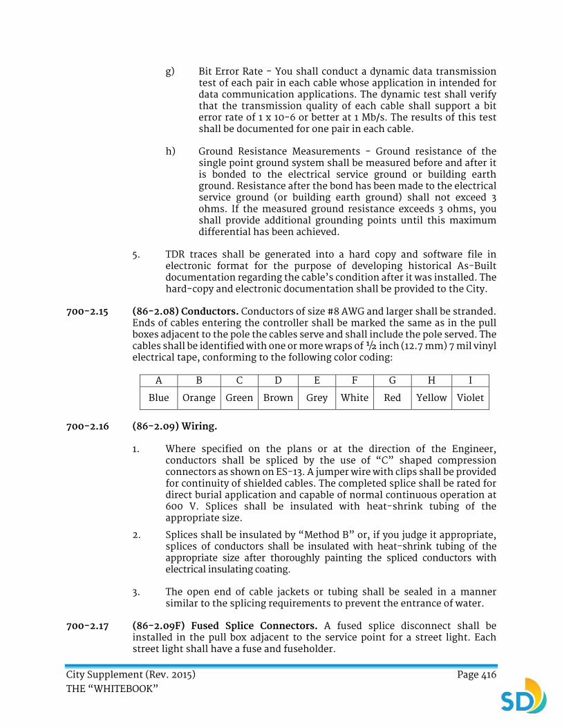
City Supplement (Rev. 2015) Page 416 THE “WHITEBOOK”
g) Bit Error Rate - You shall conduct a dynamic data transmission test of each pair in each cable whose application in intended for data communication applications. The dynamic test shall verify that the transmission quality of each cable shall support a bit error rate of 1 x 10⁻⁶ or better at 1 Mb/s. The results of this test shall be documented for one pair in each cable.
h) Ground Resistance Measurements - Ground resistance of the single point ground system shall be measured before and after it is bonded to the electrical service ground or building earth ground. Resistance after the bond has been made to the electrical service ground (or building earth ground) shall not exceed 3 ohms. If the measured ground resistance exceeds 3 ohms, you shall provide additional grounding points until this maximum differential has been achieved.
5. TDR traces shall be generated into a hard copy and software file in electronic format for the purpose of developing historical As-Built documentation regarding the cable’s condition after it was installed. The hard-copy and electronic documentation shall be provided to the City.
700-2.15 (86-2.08) Conductors. Conductors of size #8 AWG and larger shall be stranded. Ends of cables entering the controller shall be marked the same as in the pull boxes adjacent to the pole the cables serve and shall include the pole served. The cables shall be identified with one or more wraps of ½ inch (12.7 mm) 7 mil vinyl electrical tape, conforming to the following color coding:
A B C D E F G H I
Blue Orange Green Brown Grey White Red Yellow Violet
700-2.16 (86-2.09) Wiring.
1. Where specified on the plans or at the direction of the Engineer, conductors shall be spliced by the use of “C” shaped compression connectors as shown on ES-13. A jumper wire with clips shall be provided for continuity of shielded cables. The completed splice shall be rated for direct burial application and capable of normal continuous operation at 600 V. Splices shall be insulated with heat-shrink tubing of the appropriate size.
2. Splices shall be insulated by “Method B” or, if you judge it appropriate, splices of conductors shall be insulated with heat-shrink tubing of the appropriate size after thoroughly painting the spliced conductors with electrical insulating coating.
3. The open end of cable jackets or tubing shall be sealed in a manner similar to the splicing requirements to prevent the entrance of water.
700-2.17 (86-2.09F) Fused Splice Connectors. A fused splice disconnect shall be installed in the pull box adjacent to the service point for a street light. Each street light shall have a fuse and fuseholder.

City Supplement (Rev. 2015) Page 417 THE “WHITEBOOK”
700-2.18 (86-2.11A) Service.
1. Install Type III service equipment enclosure for combined 120 V metered traffic signals and 120 V unmetered street lighting as noted on the plans. Maximum base size of service equipment enclosure shall not exceed 16 inches x 16 inches (406.4 mm x 406.4 mm) and service equipment shall meet all SDG&E requirements. Traffic signal service shall have 50 A, 1P, 120 V main circuit breaker, and street lighting service shall have 30 A, 1P, 120 V main circuit breaker, unless noted otherwise on the plans.
2. Continuous welding of exterior seams in service equipment enclosures is not required.
3. Type III service equipment enclosures shall be the aluminum type.
4. Circuit breakers shall be the cable-in/cable-out type, mounted on non-energized clips. All circuit breakers shall be mounted vertically with the up position of the handle being the “ON” position.
5. Dead front panel or panels, and corresponding exterior door, shall be hinged on one side and shall be openable without the use of tools.
6. A barrier-type terminal block rated for 40 A, minimum, shall be provided in each service equipment enclosure. The terminal block shall have a minimum of 12 positions with terminals rated at Size No. 8 or larger, to accept the field wires indicated on the plans. Field wires shall be terminated using crimped, insulated loop connectors.
700-2.19 (86-2.11A) Solar Electric Power System. Where shown on the plans, a solar electric power system shall be provided. The system shall consist of solar modules, batteries, a charge regulator, mounting hardware, and the necessary wiring.
700-2.19.1 Solar Electric Modules. Solar electric modules for school zone flashers shall use triple junction thin film technology. Twenty-four-hour systems may use the thin film or polycrystalline modules. Thin film module electrical characteristics shall be 16.5 V DC maximum power voltage and 23.8 V DC open circuit voltage under standard test conditions of 1000 W/m² at 77 F (25 C). Polycrystalline module electrical characteristics shall be 16.9 V DC maximum and 21.5 V DC open circuit voltage under standard test conditions of 1000 W/m² at 77 F (25 C). The cell shall be fabricated on a stainless steel back sheet. Cells shall include an integral bypass diode. Cells shall provide the required module wattage and be encapsulated under low-iron glass.
700-2.19.2 Batteries. Systems shall include between 1 and 4 sealed valve regulated lead-acid batteries depending on autonomy and load requirements. Battery size shall be group 27. Battery ratings shall be 12 V DC, 98–105 Amp-hours and the C/100 rate or similar. Plate chemical composition shall be of lead-calcium. The case and cover material shall be polypropylene. The terminal configuration shall be T881 designed for a ¼ inch (6.4 mm) bolt. Batteries shall be filled with electrolyte

City Supplement (Rev. 2015) Page 418 THE “WHITEBOOK”
suspended in a thixotropic gel or an absorbed glass mat which allows the battery to be placed upright or on its side. Batteries shall be designed for solar applications and shall come with a prorated warranty for such applications. A data sheet for the battery showing lifetime versus cycle depth at 25 EC shall be included.
700-2.19.3 Charge Regulator.
1. The unit shall be an integrated system control unit with the capability to control power and load management functions. Basic features shall include charging of the system batteries based on voltage and temperature, low voltage disconnect to protect the batteries from over-discharge, and operation of the flasher circuit.
2. The unit shall have an external trigger input for system activation by external sources such as timers, detectors, and devices incorporating a switch/contact closure and shall include a select switch for this. The controller shall include a series switch-configured charge controller which controls the flow of array current to the battery.
3. The charging algorithm shall be a pulse type that features temperature-compensated charging. On-board short circuit protection shall be standard. The controller shall have two lamp outputs set for a 50% duty cycle each and normally calibrated for 50-60 flashes per minute to meet ITE and MUTCD standards.
4. Outputs shall be complimentary-one on and the other off. Automatic intensity adjustment of the lamps shall be made by the controller for variance in light conditions. Dimming circuitry shall be integral to the controller. Electronics shall be potted or coated to protect against environmental damage.
5. The unit shall feature an integral heat sink and an 8-position terminal strip with all positions labeled for ease of servicing. Manual switches shall be provided on the controller to select the lamp activation source (on continuous or external activation) and the dimming circuit activation. Dimming shall be capable of being defeated for school zone systems.
700-2.19.4 Mounting Hardware.
1. Solar modules shall include an aluminum frame to allow for ease of mounting and rigidity. Solar modules shall be mounted to a fixed tilt mounting structure set to an angle of 45E-50E. The mount shall be constructed of galvanized steel (ASTM A-153 Class A) or clear anodized aluminum. The mount shall be suitable for use with a Type 1-A pole. The mount will include appropriate stainless steel hardware to secure the modules to the mounting structures.
2. The system shall be housed in a gasketed enclosure, constructed of 1/4 inch (6.4 mm) aluminum, and designed for mounting on a 14 feet (4.2 m) Type 1-A pole. The enclosure shall have room for a vertical aluminum

City Supplement (Rev. 2015) Page 419 THE “WHITEBOOK”
mounting plate capable of holding the system controller and the timer module (school zone systems).
3. The battery section of the enclosure shall feature a minimum of 1/2 inch (12.7 mm) styrofoam insulation material around the battery compartment sides to minimize transfer of heat from the enclosure wall to the battery. Screen-covered louvered vents shall be included on each side of the enclosure to allow circulation of air in the enclosure.
4. The enclosure shall feature one or more PELCO police locks to secure the contents from unauthorized access. Enclosures shall be capable of holding either two or four batteries, depending on system requirements. The door shall have a lock cover plate attached to the door with a rivet. The door shall be attached to the main enclosure with hinges that are welded or sufficiently riveted to each piece. Enclosures for four batteries shall feature a continuous hinge. A mechanical stop shall be included to prevent the door from opening more than 115.
700-2.19.5 Wiring. The system shall be provided complete with wiring necessary for installation on a Type 1-A pole. Cabinet and lamp wiring shall be color coded and include a seven-pin cannon plug in the harness to allow disconnect of the system. The plug shall be keyed with a locking mechanism to ensure proper connection. Array wiring shall be coated in UV resistant sheathing and come with cord grips for exiting the module and entry to the pole. Conductors shall be terminated with either a forked terminal or a spade terminal. Sealing lock rings or O-rings shall be used to minimize the entry of water or dust into the junction box. Module interconnect cables, if used, shall be constructed of #10 AWG with a UV resistant sheath. Cord grips shall be provided at entry and exit points to the module junction box. Conductors shall be terminated with forked terminals.
700-2.20 (86-214) Testing. Testing of control equipment and cabinet wiring, complete, will be accomplished at a facility by the City of San Diego. Testing of street lighting equipment shall include a 3-day burn, by you, with the use of shorting caps.
700-2.21 (86-2.16) Painting.
1. Where shown on the Plans or specified in the Special Provisions, all light standards, mast arms, luminaire arms, signal heads, luminaires, and electrical service cabinets shall be painted the specified color. In the Centre City Community, the specified color is known as CCDC dark blue (Sherwin Williams F63TXL-1075-4365, Tnemec 75-J6179, or equal).
2. Steel surfaces shall be prepared either by Power Tool Cleaning per Section 310.2.4, or Commercial Blast Cleaning conforming to 310-2.5.1(d), “General”. New ungalvanized ferrous and non-ferous metal surfaces shall to be prepared per section 310, “Painting”. Coating system shall be Sherwin Williams (as listed below), Tnemec 75-J6179, or approved equal:
a) Wash Prime Coat: Sherwin Williams, Industrial Wash Primer, P60g2, 0.2-0.4 mil dry film thickness

City Supplement (Rev. 2015) Page 420 THE “WHITEBOOK”
b) Prime Coat: Sherwin Williams Tile-Clad II Hi-Build Primer, B62N 71/B60V 70, 4mils dry film thickness
c) First Finish Coat: Specified color, or Sherwin Williams F63TXL-1075-4365, 2 mils dry film thickness
d) Second Finish Coat: Specified color, or Sherwin Williams F63TXL-1075-4365, 2 mils dry film thickness
3. You shall touch up marred or abraded areas with a matching paint.
700-3 CONTROLLER ASSEMBLIES.
700-3.1 (86-3.01) Controller Assemblies.
1. Traffic signal controllers shall conform with the latest edition of Standard Specifications, State of California, Department of Transportation, “Section 86”, and “Traffic Signal Control Equipment Specifications”, State of California. Controller assemblies shall be on the current State of California Qualified Products List (QPL). Traffic Signal Control Equipment Specifications shall have precedence over Caltrans Standard Specifications.
TABLE 700-3.1 Controller Assembly
Model
332L
Cabinet
Model
336
Cabinet
Model
337
Cabinet
Description
1 1 1 Model 170E controller unit* with Model 412C system memory module and Power Distribution Assembly #2 (PDA #2)
1 1 1 Aluminum cabinet wired for and including the necessary accessories for full operation except as noted
1 1 1 Model 210 monitor unit
4 2 2 Model 242 two-channel isolator
12 12 6 Model 200 switch pack
1 1 1 Model 27256 programming chip (blank)
1 1 1 Model 404 Modem w/harness
16 8 4 Model 222 two-channel loop detector sensor unit

City Supplement (Rev. 2015) Page 421 THE “WHITEBOOK”
*When specified, use Model 170E Master Controller Unit with C2 connector and C20 connector.
2. The doors of the cabinets shall be hinged so that the doors swing away from the curb or street.
3. When the controller assembly is to be furnished in a Model 336 cabinet with base adaptor, the cabinet shall be constructed in accordance with the Controller specification for Model 332L aluminum cabinet but with the configuration shown in Figure 3.
4. Each cabinet shall be equipped with a single fluorescent fixture with front and rear door activating switches, and slide-out document drawer. Cabinet finish shall be anodized aluminum with clear anti-graffiti coating except when a paint finish is specified.
5. Front panel character display modules shall be socket mounted for easy replacement in the front panel assembly.
700-3.2 (86-3.04E) Model 200 Switch Packs. Model 200 switch packs shall be capable of operating Type "G" pedestrian signals without exceeding Model 210 conflict monitor threshold limits and shall be capable of switching a single L.E.D. head.
700-3.3 (86-3.04E) Model 412C System Memory Module. The module shall be designed so that persons inserting or removing the assembly shall not be required to insert hands or fingers within the controller unit housing this modular assembly. A handle or gripping device protruding no more than 1¼ inches (31.8 mm) from the front panel shall be attached to the front of the assembly. The front panel shall be connected to equipment ground. The front panel of the module shall be labeled “SYSTEM MEMORY MODULE MODEL 412C”. Socket for 27256 EPROM chip shall be marked on the board adjacent to each socket designating the following descriptive: MS and LS.
700-3.4 (86-4.05) School Zone Flashing Beacon System Timer Module. The system timer module shall have the following minimum standard features:
1. Alphanumeric LCD display.
2. 48-hour capacitive backup.
3. 15 A SPDT relay output.
4. 16-key input keypad.
5. Auto-leap year compensation.
6. Auto-prompt for programming.
7. Crystal clock source.
8. Operating temperature range of -22° F to 165.2° F (-30° C to 74° C).
9. Solid-state construction except for the relay.
10. Auto-daylight savings time adjustment.
11. Compatible with nominal 12 V DC operation.

City Supplement (Rev. 2015) Page 422 THE “WHITEBOOK”
The unit shall be capable of exception periods when operation can be suspended or optional programs can be run for periods such as holidays or special events. Program steps shall allow the programming of a single day, weekend, or week days.
700-4 (86-4) TRAFFIC SIGNAL FACES AND FITTINGS.
700-4.1 (86-4.01) Signal Faces and Signal Heads.
1. Signal head sections, except programmed visibility type heads, shall be metal with metal visors and metal back plates. Visors shall be tunnel-type, have ears and be attached to the signal heads with screws. Visors shall interchange with Econolite, Traffic Control Technologies, McCain, and Automatic Signal manufactured vehicle heads.
2. All new signal faces and all arrow indications shall be provided with 12 inch (305 mm) sections unless shown otherwise on the plans. Lenses shall interchange with Econolite, Traffic Control Technologies, Automatic Signal, and McCain manufactured vehicle heads.
3. Type SV-1-T mountings with 5 sections and SV-2-TD mountings shall be strapped to the standard using ½ inch (12.7 mm) stainless steel strapping material and a stainless steel standoff.
4. Except for programmed visibility heads, the red, yellow, and green indications shall be Type 1 Light Emitting Diode (LED) signal modules conforming to the latest Caltrans specifications. A maintenance period is not required. Replacement modules shall be provided promptly after receipt of modules that have failed at no cost to the City except cost of shipping of the failed modules. All warranty documentation shall be given to the Engineer prior to installation. The replacement modules shall be delivered to the City’s Street Division-Electrical Section at Chollas Operations Station, 2781 Caminito Chollas, San Diego, CA 92105 within 5 Working Days after notification.
5. Where solar electric power is provided for a flashing beacon, the indication(s) shall be yellow or red Light Emitting Diode (LED) signal modules conforming to the latest Institute of Transportation Engineers specifications. A maintenance period is not required. Replacement modules shall be provided promptly after receipt of modules that have failed at no cost to the City except cost of shipping of the failed modules. All warranty documentation shall be given to the Engineer prior to installation. The replacement modules shall be delivered to the City’s Street Division/Electrical Section at Chollas Operations Station, 2781 Caminito Chollas, San Diego, CA 92105 within 5 Working Days after notification.
6. Traffic signal heads shall be green with black doors unless otherwise specified in the plans or specifications.
700-4.2 (86-4.02) Programmed Visibility Vehicle Signal Faces. Lamps shall be furnished by you. You shall arrange to have a signal technician qualified to

City Supplement (Rev. 2015) Page 423 THE “WHITEBOOK”
program the programmed visibility signal heads present at the time the signal heads are placed in operation. Lamps for the signal units shall be 150 W, 120 V, incandescent lamps with a minimum average rated life of 6,000 hours. The lamp and socket shall be the 3-prong type.
700-4.3 (86-4.03) Types.
1. Pedestrian signals shall be Type “G”.
2. Each pedestrian signal shall consist of a housing with front screen, a message plate, and two Light Emitting Diode (LED) modules, Pedestrian signal housings shall be metal with metal visors and shall conform to provision in Section 86-4.01. All pedestrian signals shall incorporate a pedestrian countdown timer indication.
3. The message plate shall be 1/8 inch (3.2 mm) nominal thickness ultra-violet-stabilized, prismatic-patterned polycarbonate plastic; 3/16 inch (4.8 mm) nominal thickness hammered wire glass; or 3/16 inch (4.8 mm) nominal thickness ultraviolet-stabilized, prismatic-patterned acrylic plastic. The message plates shall have a flat-black surface over the entire projected area except where the symbols are located. The material used to mask the message plate shall be hard and durable and shall bond in such a manner that it will not flake or peel when the message plate is in use or is washed. The symbols shall be the only illuminated portion of the message plate. The message plate shall be sealed to a polycarbonate case to form a dust-tight and weather-proof module.
4. For crossings where the distance from the near curb to the pedestrian signal indication is 60 feet (18.3 m) or less, the luminance of the UPRAISED HAND symbol shall be 960 cd/m2 (280 footlamberts), minimum, and the luminance of the WALKING PERSON symbol shall be 3,400 cd/m2 (990 footlamberts) minimum.
700-4.4 (86-4.03) Audible Pedestrian Signals.
1. Audible pedestrian signals shall be installed in conjunction with each visual pedestrian signal head where shown on the plans.
2. The audible pedestrian signal shall consist of a weather-proof audio signal device operating continuously during the protected walk interval of the corresponding visual pedestrian signal when actuated by the corresponding pedestrian push button. The output volume of the audio signal shall automatically adjust to the ambient noise level in the intersection. East-west crosswalks shall be designated by a “Beep-Beep” electronic bird chirping. North-south crosswalks shall be designated by a “Cuckoo” electronic bird chirping.
3. Audible signal device speaker shall be mounted facing down in location shown on the attached, “Audible Pedestrian Signal Details”.
700-4.5 (86-4.03) Accessible Pedestrian Signals. Accessible pedestrian signal shall consists of an integrated push button assembly with vibrotactile button,

City Supplement (Rev. 2015) Page 424 THE “WHITEBOOK”
programmable verbal message, locator tone with automatic volume adjustment to ambient noise.
700-4.6 (86-4.04) Signal Mounting Assemblies. Signal faces installed prior to signal operation shall be covered with shade cloth, canvas, or similar. Cardboard is not an acceptable cover material. Mast arm slip-fitters, post top slip-fitters, and terminal compartments shall be cast bronze.
700-4.7 (86-4.05) Flashing Beacons. Flashing beacons installed at school locations shall be equipped with a solid-state programmable timer with digital display as specified in 700-3.4, “School Zone Flashing Beacon System Timer Module”.
700-5 (86-5) DETECTORS.
700-5.1 (86-5.01) Vehicle Detectors.
1. Loop wire shall be Type 1. Loop detector lead-in cable shall be Type “B”. Slots shall be filled with elastomeric sealant, epoxy sealant, or hot-melt rubberized asphalt sealant, except asphaltic emulsion loop sealant and cold tar loop sealant are acceptable if the pavement surface will receive an asphaltic concrete overlay.
2. Vehicle detector loops shall be Type E or Type E Modified as shown on the plans. Bicycle detector loops within bicycle lanes shall be Type Q. For Type E detector loops, sides of the slot shall be vertical and the minimum radius of the slot entering and leaving the circular part of the loop shall be 1½inches (38.1 mm). Slot width shall be a maximum of 3/4 inch (19.1 mm). Type E detector loops shall have three turns of conductor. Limit line vehicle detector loops (front loops) shall be Type E Modified loops. Type E Modified loops shall have four turns of conductor.
3. The sand mixed with the epoxy loop sealant shall be clean and dry silica sand and shall be smaller than 1,520 μm (pass a No. 12 sieve) and be no smaller than 860μm (retained on a No. 20 sieve). The adhesive shall be a black, low viscosity material consisting of equal parts of modified coal tar epoxy resin and modified amine-bitumen hardening agent, equal to Epocast H-1136A and 1136B. Adhesive shall be mixed together mechanically on the Site and shall have 30 to 45 minute pot life.
4. Fill the slot with sand. Soak the sand with adhesive overflow. Cover the slot with additional sand. Before the adhesive sets, strike off excess material flush with pavement and remove from adjacent road surfaces.
700-5.2 (86-5.01A) Preformed Inductive Loops.
1. Preformed inductive loops shall be the type shown on the plans. The loop shall be 6 feet (1.8 m) square unless otherwise shown. The loop shall consist of 4 turns of No. 16, or larger, wire with Type THWN or TFFN insulation. The loop wires shall be encased in Size 10, minimum size, Schedule 40 or Schedule 80 PVC or polypropylene conduit. The conduit shall be sealed to prevent the entrance of water and the movement of wires within the conduit. The loop wires from the preformed loop to the

City Supplement (Rev. 2015) Page 425 THE “WHITEBOOK”
adjacent pull box shall be twisted together into a pair (at least 7 turns per meter (2 turns per foot)) and encased in Schedule 40 or Schedule 80 PVC or polypropylene conduit between the preformed loop and the adjacent pull box or detector handhole. The lead-in conduit shall be sealed to prevent the entrance of water at the pull box or handhole end.
2. In new roadways, the preformed loops and lead-in conduits shall be placed in the base course, with top of conduit flush with top of base, and then covered with the asphalt concrete or PCC pavement. Preformed loops and lead-in conduits shall be protected from damage prior to and during pavement placement.
3. In new reinforced concrete structure decks the preformed loops shall be secured to the top of the uppermost layer of reinforcing steel using nylon wire ties. The loop shall be held parallel to the structure deck by using PVC or polypropylene spacers where necessary. Conduit for lead-in conductors shall be placed between the uppermost 2 layers of reinforcing steel.
4. In existing pavement, preformed loop installation shall conform to the following:
a) The preformed loops and lead-in conduits shall be placed in slots, 1/4 inch (6.4 mm) minimum width, cut into the existing pavement. The top of the conduit shall be 1 inch (25.4 mm), minimum, below the top of pavement.
b) Slots in asphalt concrete pavement shall be filled with elastomeric sealant, epoxy sealant, or hot-melt rubberized asphalt sealant.
c) Slots in portland cement concrete shall be filled with elastomeric sealant or hot-melt rubberized asphalt sealant, or shall be filled with epoxy sealant conforming to the requirements in Section 95-2.09, “Epoxy Sealant for Inductive Loops” of the Standard Specifications.
700-5.3 (86-5.02) Pedestrian Push Button Assemblies.
1. Pedestrian push buttons shall be Type “B”. Actuator shall have a minimum diameter of 2 inches (50.8 mm) and an operating force of 2.5 N to 3.6 N (9 ounces to 13 ounces) and a release force of 1 N (3.5 ounces).
2. Pedestrian push button signs shall conform to the size shown on Standard Plan ES-5C. Signs shall display international "Walking Person" symbol and directional arrow. Pedestrian push button housing shall be mounted with the actuator button at 3 feet 3 inches ± 1 inch (1 m ± 25.4 mm) above the adjacent finished grade.
700-6 (86-6) LIGHTING.
700-6.1 (86-6. 11) Photoelectric Controls.
1. The photoelectric control unit (PCU) shall be Type "IV".

City Supplement (Rev. 2015) Page 426 THE “WHITEBOOK”
2. Furnish an individual, stand-alone PCU with each fixture. An Adaptive Control Node shall be provided unless otherwise specified on the Plans or in the SSP. The PCU shall have a silicon light sensor that complies with ANSI 136.10 – 2010, and have MOV surge protection. The PCU shall have a minimum ten year warranty. The PCU shall fail in the “on” control. It shall be capable of inverse ratio controls. It shall be suitable for roadway applications.
3. The PCU shall be American Electric Lighting model number DP 124-1.5-T-J-BK or approved equal.
4. Photoelectric units for illuminated signs shall have a “turn-on” level of between 215 lux and 323 lux (20 footcandles and 30 footcandles) corresponding to a switching level of approximately 430 lux to 646 lux (40 footcandles to 60 footcandles) measured in the horizontal plane. The “turn-off” level shall not exceed 3 times the “turn-on” level.
5. See 700-6.3, “Adaptive Control Node” for Adaptive Control Node specifications.
6. All components shall be long life with UV inhibitors
700-6.2 LED Cobra Head Luminaire.
700-6.2.1 General.
1. Each luminaire shall consist of an assembly that utilizes LED components as the light source subject to the following requirements:
a) Operating Temperature: The luminaire shall be designed to operate at an average nighttime temperature of 70 F (20 C). The ambient operating temperature range shall be 30 F to 130° F (-5 C to 55 C).
b) UL Listing: The fixtures shall be UL Listed and shall include UL label. The UL listing shall include the pole mounting assembly.
c) Components: LED components shall be interchangeable amongst similar wattages for common fixtures without requiring use of special tools. Troubleshooting components shall not require special diagnostic tools or individual energy usage metering systems.
700-6.2.2 Electrical Requirements.
1. Operating Voltage: The luminaire shall operate within one of two voltage categories (95 to 305 and 480) Volts AC (VAC). The fixtures shall be capable of operating in the range of voltages listed. Fluctuations of line voltage within these categories shall have no visible effect on the luminous output. External Transformers are not permissible as components for the luminaire input voltage.

City Supplement (Rev. 2015) Page 427 THE “WHITEBOOK”
2. Power Factor: Power supply should have a minimum Power Factor of 0.90.
3. Harmonic Distortion: The total harmonic distortion shall not exceed 20%. An integral factory installed standard driver is required that includes inherent thermal protection.
4. Surge Suppression: The luminaire on-board circuitry shall include Surge Suppression Devices (SSD) to withstand high repetition noise transients as a result of utility transients, and other interference. SSD shall conform to UL 1449 or UL 1283, depending on the components used in the design.
700-6.2.3 Controls.
1. Photocell Receptacle: Each luminaire shall have a rotatable (so the window can be adjusted to the north) prewired 7-conductor (twist-lock) ANSI C136.41-2013 photocell receptacle.
2. Furnish an Adaptive Control Node for each luminaire. See 700-6.3, “Adaptive Control Node” for Adaptive Control Node specifications.
3. All components shall be long life with UV inhibitors
700-6.2.4 Cooling System.
1. Thermal management of the heat generated by the components shall be of sufficient capacity to assure proper operation of the luminaire over the expected useful life of more than 100,000 hours at specified operating temperature range and climate zone.
2. The light output variation shall not deviate greater than 15% over 40° F to 130°F (0° C to 55° C) operating temperature variation.
3. Thermal management shall be passive by design and shall consist of a heat sink with no moving mechanical parts or liquids.
700-6.2.5 Roadway Application Requirements and Optical Assembly.
1. Correlated Color Temperature (CCT): CCT shall be 3000 or 4000 Kelvin depending on location and as indicated on the Plans.
2. Color Rendering Index (CRI): Luminaires shall have a minimum CRI of 70.
3. Optics: The luminaire shall conform to the Illuminating Engineering Society (IES) definition of “cut-off”, with no illumination above an angle of 90 degrees above the nadir. The fixtures shall be International Dark-Sky Association (IDA) compliant. Submittal documentation shall include “Dark Sky” compliance.

City Supplement (Rev. 2015) Page 428 THE “WHITEBOOK”
700-6.2.6 Physical/Mechanical Requirements.
1. Luminaire Fixture: The luminaire shall be a single, self-contained device, not requiring on-Site assembly for installation. The power supply for the luminaire shall be integral to the unit.
2. Maximum Dimensions: 40 inch long by 16 inch wide by 8 inch tall (101.6 cm long by 40.6 cm wide by 20.3 cm tall).
3. Luminaire shall not weigh more than 40 pounds (18 Kg).
4. Assembly Housing: The housing shall be primarily constructed of dye cast aluminum or steel corrosion resistant paint. Finish shall be gray in color, powder coated and rust resistant. The fixture openings and doors shall be sealed and gasketed. The components within the fixture assembly shall be easily accessible with a two-piece hinged door separable from the upper assembly. The lower door shall be removable. All screws shall be stainless steel. Captive screws are required on accessible components that require maintenance after installation. Lens discoloration shall be considered a failure under warranty.
5. Access: Provide easy access to internal components. Include an external latch capable of being operated with one hand. No internal components shall fall out when the lower door assembly is opened. Seams shall be CNC formed and TIG welded.
6. Lens Requirements: The lens shall be tempered glass 1/4 inch (6.4 mm) thick lens, or approved equal with gasketed door.
7. Mast Arm Mounting Connection Requirements: Luminaires shall mount on min 1-5/8 inch (4.13 cm) OD to max 2-3/8 inch (6.03 cm) OD horizontal tenon with no more than four 9/16 inch (1.43 cm) hex bolts and a 2-piece clamp(s). Luminaire leveling capability shall be integral to the fixture. Multiple mounting angle adjustments shall be provided to adjust the level of the fixture ± 4° from the horizontal.
8. Mechanical Requirements: The assembly and manufacturing process for the induction luminaire shall be designed to assure all internal components are adequately supported to withstand mechanical shock and vibration from winds.
9. Ingress Protection (IP) Rating: Optical assembly shall have a minimum rating of IP-65, the exterior shell shall have a minimum IP rating of 54.
10. Terminal Block: Field wires connected to the luminaire shall terminate on a barrier type terminal block secured to the housing. The terminal screws shall be captive and equipped with wire grips (serrated strips on the terminal for conductors up to #6 AWG wire size). Each terminal position and conductor phase designation shall be clearly identified.
11. Components: All components, including circuit boards, shall conform to Chapter 1, Section 6 of the “Transportation Electrical Equipment
City Supplement (Rev. 2015) Page 429 THE “WHITEBOOK”
Specifications” (TEES) UL 1598, and ANSI C 136 requirements. Fixture components shall be modular in design and recyclable.
12. Painting: Powder coat painting of the housing shall conform to the requirements of the Caltrans Standard Specifications and the SSP. Applied coating shall be free of lead and mercury.
13. House Side Shield: The manufacturer shall offer a field installable house side shield.
700-6.2.7 Luminaire Identification.
1. Identification: Each luminaire shall have the manufacturer’s name, trademark, model number, serial number, date of manufacture including month and year, and lot number as identification permanently marked inside each unit and the outside of each packaging box.
2. Identification: The wattage and CCT rating of the luminaire shall be able to be detected visibly from an observer standing at ground elevation at the base of the pole.
3. Identification of Operating Characteristics: The following operating characteristics shall be permanently marked inside each unit: rated voltage and rated power in Watts and Volt-Ampere, and Luminaire Efficiency Rating (LER).
700-6.2.8 Photometric Documentation. IES Files: Submittals shall include IES files for each fixture type. Submittals shall include photometric iso-foot candle diagram for a 30 feet (9.14 m) mounting height for each fixture type, and a point to point diagram with uniformity calculations that identify maximum to minimum illumination ratio. Photometric diagrams shall be in a scale of 1:20.
700-6.2.9 Quality Assurance. Luminaires shall be manufactured in accordance with ISO9001. The Manufacturer’s Warranty Certificate shall be in accordance with 6-8.3, “Warranty” and submitted in accordance with 2-5.3, “Submittals”.
700-6.3 Adaptive Control Node.
700-6.3.1 General.
1. The adaptive control node (controller) shall consist of an assembly with the following features and requirements:
700-6.3.2 Control System Interface.
1. The controller shall transmit to the system the following values on a system of at least 250,000 controllers:
a) Voltage RMS
b) Current RMS
c) Power Factor
City Supplement (Rev. 2015) Page 430 THE “WHITEBOOK”
d) Wattage
e) Temperature
f) Physical Location
g) Controller Local Time GMT
h) Network Address
i) Network Parent
j) RF Signal Strength
k) Total Hours Controller
l) Total Hours Load
m) Active Schedule
n) Next Scheduled Event Time
o) Current Firmware Version
p) Firmware Upload Version
2. The system shall support load identification via searchable fields that include:
a) Physical address
b) Unique Billing Identification Number
c) Pole Material Type
d) Load Wattage
e) Installation Date
f) Pole Number
3. The system shall support SMTP or SMS user notifications for all measurement value reported outside of user defined limits
4. All measurement data will be automatically stored in the CMS data base at a user defined interval of 15 minutes to 24 hours
5. The System CMS shall be hosted by the customer or at his specified hosting partner location
6. The Gateways shall support both cabled (copper or fiber) and wireless backhaul connectivity (cellular or equivalent)
700-6.3.3 Asset Management.
1. All System controllers shall be equipped with an internal GPS receiver
2. GPS location reporting error will in all cases be less than 3 meters when satellite signals are not obstructed

City Supplement (Rev. 2015) Page 431 THE “WHITEBOOK”
3. All system components will automatically register and be displayed in the MAP view of the deployment area
4. A total of all Controllers registered will be prominently displayed on the MAP view of the Graphic user interface
5. A total of all Controllers in the error state will be prominently displayed on the MAP view of the Graphic user interface
700-6.3.4 Energy Metering and Billing Data Transfer.
1. All controllers shall contain a subsystem that complies to ANSI 12.20- 0.5% Metering Accuracy Class
2. The controller shall in all cases report the combined total of all energy consumed by both the controller and the load
3. Energy metering shall start within 3 seconds of power being applied to the controller
4. Power outage recovery events shall not result in more than 3 seconds of unmetered energy consumption
5. The system shall export energy consumption for each controller at a minimum of once every 24 hours
6. The system shall report the total energy consumption in 15 minute intervals that shall end on the 1/4 hour GMT (IE 00:15:30:45)
7. All Data shall be formatted and transferred in accordance to ANSI-X12 formatting criteria and Transaction Set 867 Ver/Rel 004010, meter Interval and Historical Usage Reporting Version 1.1 Jul 16, 2006
700-6.3.5 Wireless Mesh.
1. The Wireless Lighting Control system shall:
a) Utilize license free 915 MHz spectrum.
b) In all cases provide a wireless connection to all other controllers or gateways within 1650 feet (502.9 m) free from obstacles.
c) Transmit using a randomly selected channel from a group of a minimum of 50 discrete channels to minimize interference.
d) Comply with all IEEE 802.154 g PHY communication standard requirements.
e) Comply with all IETF 6LoWPAN communication standard requirements.
f) Utilize a self-forming and self-restoring mesh communications protocol.
700-6.3.6 Security.
1. All System Components will be assigned a unique permanent serial number by the manufacture (MAC ADDRESS)
2. All System Components will only use a system wide unique IPV6 address reference, no dynamic address schemes

City Supplement (Rev. 2015) Page 432 THE “WHITEBOOK”
3. All Wireless Connections will utilize a unique 128 bit ECC encryption key 256 bit Certificate Authority registered authentication key
4. All Wired Connections will utilize a unique 256 bit encryption key and a 256 bit Certificate Authority registered authentication key
5. All encryption & authentication keys will be wirelessly revocable & updateable by the user should they be compromised
700-6.3.7 Dimming (Power Trimming).
1. All controllers shall continuously adjust the load consumption within 2% of the user defined target over the full temperature range
2. All controllers shall utilize a power change ramp rate of 1 second per 1% of total load wattage change
3. All controllers shall support Lumen Maintenance and Constant light output over the life of the load (default is LM70)
700-6.3.8 Mechanical.
1. All controller and gateway electronic components and printed circuit boards shall be conformal coated.
2. The controller housing shall be rated IP54 and allow any moisture to drain without affecting operation
3. The Gateway housing shall be rated IP66 and allow any moisture to drain without affecting operation
4. The total power consumption for the gateway shall not exceed 3W @120-240 VAC
5. The total power consumption for the controllers shall not exceed 2W @120-240 VAC
6. Controllers shall be integrated (mechanically and electrically connected) at the luminaires using a NEMA C136.41 standard polarized twist-lock receptacle or equivalent for both electrical and dimming control signal connectivity.
7. The rated life of all Field Devices shall be 15 years or more at an ambient temperature of 45° F (25° C).
8. All controllers shall be UL listed.
700-6.3.9 Warranty.
1. All Field devices shall be covered by a single-source written replacement warranty covering material and workmanship for a period of 10 years.
2. All software and firmware shall be covered by a written replacement warranty covering material and workmanship for a period of 2 years.

City Supplement (Rev. 2015) Page 433 THE “WHITEBOOK”
700-7 (86-7) REMOVING, REINSTALLING, OR SALVAGING ELECTRICAL EQUIPMENT.
700-7.1 (86-7.01) Removing Electrical Equipment. Salvaged equipment not reused on the Project shall be delivered to the General Services Transportation & Storm Water Department, Street Division, Electrical Section at Chollas Operations Station, 2781 Caminito Chollas, San Diego, CA, and stockpiled. Delivery time and location shall be coordinated with the City at Telephone No. (619) 527-8031, a minimum of 1 Working Day in advance of desired delivery date. You shall provide equipment, as necessary, to safely unload and stockpile the material. You shall obtain an appropriate receipt upon delivery. You shall tag each pole and mast arm with the size and type using an indelible ink marker.
700-7.2 (86-7.02) Reinstalling Removed Electrical Equipment. When removed electrical equipment is to be reinstalled on a new or different size pole, you shall furnish and install all new mounting equipment including all necessary signal mounting assemblies, anchor bolts, nuts, washers and concrete as required for completing the installation.
700-8 EMERGENCY VEHICLE PREEMPTION EQUIPMENT (EVPE).
700-8.1 General.
1. Each traffic signal, where shown on the Plans, shall have a modulated light signal detection system which shall conform to the details shown on the plans and these special provisions. Each modulated light signal detection system shall consist of an optical detector/discriminator assembly or assemblies located at the traffic signal. Emitter assemblies are not required for this project.
2. Each system shall permit detection of two classes of authorized vehicles. Class I (mass transit) vehicles shall be capable of being detected at any range of up to 1,800 feet (548.6 m )from the optical detector. Class II (emergency) vehicles shall be capable of being detected at any range up to 2,500 feet (762 m) from the optical detector.
3. Class I signals (those emitted by Class I vehicles) shall be distinguished from Class II signals (those emitted by Class II vehicles) on the basis of the modulation frequency of the light from the respective emitter. The modulation frequency for Class I signal emitters shall be 9.63855 Hz.
4. A system shall establish a priority of Class II vehicle signals over Class I vehicle signals, and shall conform to the requirements in Section 25352, of the California Vehicle Code. Standard emitters for both classes of signals shall be available from the manufacturer of the system. Range measurements shall be taken with all range adjustments on the discriminator module set to “Maximum”.
700-8.2 Optical Detection/Discriminator Assembly.
700-8.2.1 General.
1. Each optical detection/discriminator assembly shall consist of one or more optical detectors, connecting cable(s), and discriminator module.
2. Each such assembly, when used with standard emitters, shall have a range of at least 1,800 feet (548.6 m) for Class I signals and 2,500 feet (762 m) for Class II signals. Standard emitters for both classes of signals shall be available from the manufacturer of the system. Range

City Supplement (Rev. 2015) Page 434 THE “WHITEBOOK”
measurements shall be taken with all range adjustments on the discriminator module set to “maximum”.
700-8.2.1.1 Optical Detector.
1. Each optical detector shall be a weatherproof unit capable of receiving optical energy from two separately aimable directions. The horizontal angle between the two directions shall be variable from 180 to 5. The reception angle for each photocell assembly shall be a maximum of 8 degrees in all directions about the aiming axis of the assembly. Measurements of reception angle will be taken at a range of 1,800 feet (548.6 m) for a Type I emitter and at a range of 2,500 feet (762 m) for a Type II emitter. Each optical detector shall be installed, wired, and aimed as specified by the manufacturer. Mast-arm mounted optical detectors shall utilize clamping hardware shown in the attached, “E.V.P.E. Detector Mounting Details”.
2. Internal circuitry shall be solid state and electrical power shall be provided by the associated discriminator module. Each optical detector shall be contained in a housing which shall include two rotatable photocell assemblies, an electronic assembly, and a base. The base shall have an opening to permit its mounting on a mast arm or a vertical pipe nipple, or suspension from a span wire. The mounting opening shall have female threads for 3/4 inch (19.1 mm) conduit. A cable entrance shall be provided which shall have male threads and gasketing to permit a water-proof cable connection. Each detector shall have mass of less than 2 pounds (1.1 kg) and shall present a maximum wind load area of 36 in2 (230 cm2). The housing shall be provided with weep holes to permit drainage of condensed moisture.
700-8.2.1.2 Cable. Optical detector cable shall meet the requirements of IPCEA-S-61-492/NEMA WC 5, Section 7.4, 600 volt control cable, 75 C (165 F), Type B, and the following:
1. The cable shall contain 3 conductors, each of which shall be No. 20 (7 x 28) stranded, tinned copper with low-density polyethylene insulation. Minimum average insulation thickness shall be 25 mil (0.63 mm). Insulation of individual conductors shall be color-coded: 1-yellow, 1-blue, 1-orange.
2. The shield shall be either tinned copper braid or aluminized polyester film with a nominal 20% overlap. Where the film is used, a No. 20 (7 x 28) stranded, tinned, bare drain wire shall be placed between the insulated conductors and the shield and in contact with the conductive surface of the shield.
3. The jacket shall be black polyvinyl chloride with minimum ratings of 600 V and 80 EC (175 EF) and a minimum average thickness of 45 mils (1.1 mm). The jacket shall be marked as required by IPCEA/NEMA.
4. The finished outside diameter of the cable shall not exceed 0.35 inch (8.9 mm).
5. The capacitance, as measured between any conductor and the other conductors and the shield, shall not exceed 157 pf per meter (48 picofarads per foot) at 1,000 Hz.
City Supplement (Rev. 2015) Page 435 THE “WHITEBOOK”
6. The cable run between each detector and the controller cabinet shall be continuous without splices or shall be spliced only as directed by the detector manufacturer. Provide 20 feet (6.1 m) of slack lead-in cable for each detector. Coil cable in pull box adjacent to pole on which detector is installed.
700-8.2.1.3 Discriminator Module.
1. Each discriminator module shall be designed to be compatible and usable with a Model 170E controller unit and to be mounted in the input file of a Model 332L or Model 336 controller cabinet, and shall conform to the requirements of Chapter I of the State of California, Department of Transportation, “Traffic Signal Control Equipment Specifications”, dated April, 1978, and all addenda thereto, current at the time of project advertising.
2. Each discriminator module shall be capable of operating 2-4 channels, each of which shall provide an independent output for each separate unit. Each discriminator module, when used with its associated detectors, shall be capable of:
a) Receiving Class I signals at a range of up to 1,000 feet (304.8 m) and Class II signals at a range of up to 1,800 feet (548.6 m).
b) Decoding the signals, on the basis of frequency, at 9.639 Hz ± 0.119 Hz for Class I signals and 14.035 Hz ± 0.255 Hz for Class II signals.
c) Establishing the validity of received signals on the basis of frequency and length of time received. A signal shall be considered valid only when received for more than 0.50 second. No combination of Class I signals shall be recognized as a Class II signal regardless of the number of signals being received, up to a minimum of ten signals. Once a valid signal has been recognized, its effect shall be held by the module in the event of temporary loss of the signal for a period adjustable from 4.5 seconds to 11 seconds in at least 2 steps at 5 seconds ± 0.5 second and 10 seconds ± 0.5 seconds.
d) Providing an output for each channel that will result in a “low” or grounded condition of the appropriate input of a Model 170E controller unit. For Class I signals, the output shall be a 6.25 Hz ± 0.1 % rectangular waveform with a 50 % duty cycle. For Class II signals, the output shall be steady.
3. Each discriminator module shall receive electric power from the controller cabinet at either 24 V DC or 120 V AC.
4. Each channel, together with its associated detectors, shall draw not more than 100 mA at 24 V DC nor more than 100 mA at 120 V AC. Electric power, one detector input for each channel and one output for each channel, shall terminate at the printed circuit board edge connector pins listed in TABLE 700-8.2.1.3.
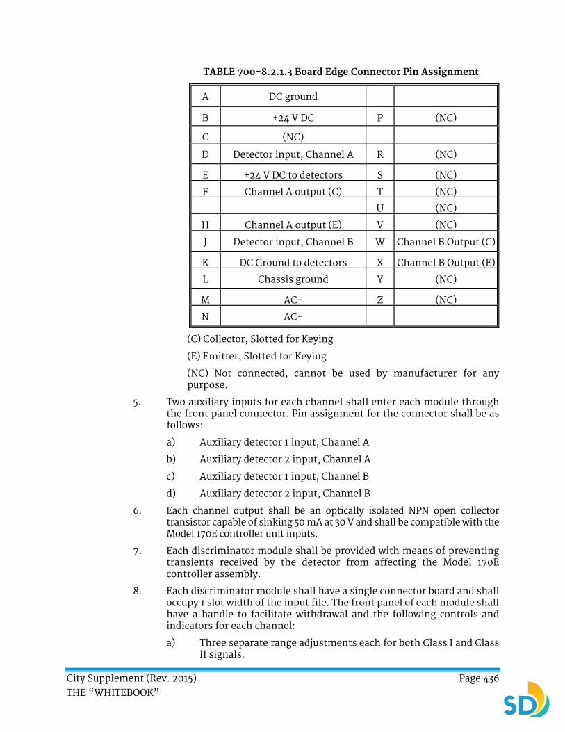
City Supplement (Rev. 2015) Page 436 THE “WHITEBOOK”
TABLE 700-8.2.1.3 Board Edge Connector Pin Assignment
A DC ground
B +24 V DC P (NC)
C (NC)
D Detector input, Channel A R (NC)
E +24 V DC to detectors S (NC)
F Channel A output (C) T (NC)
U (NC)
H Channel A output (E) V (NC)
J Detector input, Channel B W Channel B Output (C)
K DC Ground to detectors X Channel B Output (E)
L Chassis ground Y (NC)
M AC- Z (NC)
N AC+
(C) Collector, Slotted for Keying
(E) Emitter, Slotted for Keying
(NC) Not connected, cannot be used by manufacturer for any purpose.
5. Two auxiliary inputs for each channel shall enter each module through the front panel connector. Pin assignment for the connector shall be as follows:
a) Auxiliary detector 1 input, Channel A
b) Auxiliary detector 2 input, Channel A
c) Auxiliary detector 1 input, Channel B
d) Auxiliary detector 2 input, Channel B
6. Each channel output shall be an optically isolated NPN open collector transistor capable of sinking 50 mA at 30 V and shall be compatible with the Model 170E controller unit inputs.
7. Each discriminator module shall be provided with means of preventing transients received by the detector from affecting the Model 170E controller assembly.
8. Each discriminator module shall have a single connector board and shall occupy 1 slot width of the input file. The front panel of each module shall have a handle to facilitate withdrawal and the following controls and indicators for each channel:
a) Three separate range adjustments each for both Class I and Class II signals.

City Supplement (Rev. 2015) Page 437 THE “WHITEBOOK”
b) A 3-position, center-off, momentary contact switch, one position (down) labeled for test operation of Class I signals, and one position (up) labeled for test operation of Class II signals.
c) A “signal” indication and a “call” indication each for Class I and for Class II signals. The “signal” indication denotes that a signal above the threshold level has been received. A “call” indication denotes that a steady, validly coded signal has been received. These two indications may be accomplished with a single indication lamp; “signal” being denoted by a flashing indication and “call” with a steady indication.
9. In addition, the front panel shall be provided with a single circular, bayonet-captured, multi-pin connector for two auxiliary detector inputs for each channel. Connector shall be a mechanical configuration equivalent to a MIL-C-26482 with 10-4 inserts arrangement, such as Burndy Trim Trio Bantamate Series, consisting of:
a) Wall mounting receptacle, G0B10-4PNE with SM 20M-1S6 gold-plated pins.
b) Plug, G6L10-4NE with SC20M-1S6 gold-plated sockets, cable clamp, and strainer relief that shall provide for a right-angle turn with 2½ inch (63.5 mm) maximum from the front panel surface of the discriminator module.
700-8.2.1.4 Cabinet Wiring.
1. The Model 332L cabinet has provisions for connections between the optical detectors, the discriminator module, and the Model 170E controller unit.
2. Wiring the Model 332L cabinet shall conform to the following:
a) Slots 12 and 13 of input file "J" have each been wired to accept a 2-channel module.
b) Field wiring for the primary detectors, except 24 V DC power, shall terminate on either terminal board TB-9 in the controller cabinet or on the rear of input file "J", depending on cabinet configuration. Where TB-9 is used, position assignments shall be as follows:
Position Assignment
4 Channel A detector input, 1st module (Slot J-12)
5 Channel B detector input, 1st module (Slot J-12)
7 Channel A detector input, 2nd module (Slot J-13)
8 Channel B detector input, 2nd module (Slot J-13)
c) The 24 V DC cabinet power will be available at Position 1 of terminal board TB-1 in the controller cabinet.

City Supplement (Rev. 2015) Page 438 THE “WHITEBOOK”
d) Field wiring for the auxiliary detectors shall terminate on terminal board TB-0 in the controller cabinet. Position assignments are as follows:
FOR MODULE 1 (J-12) FOR MODULE 2 (J-13)
Position Assignment Position Assignment
1 +24 V DC from (J-12E) 7 +24 V DC from (J-13E)
2 Detector ground From (J-12K) 8 Detector ground from (J-13K)
3 Channel A auxiliary detector input 1
9 Channel A auxiliary detector input 1
4 Channel A auxiliary detector input 2 10 Channel A auxiliary detector input 2
5 Channel B auxiliary detector input 1 11 Channel B auxiliary detector input 1
6 Channel B auxiliary detector input 2 12 Channel B auxiliary detector input 2
700-8.2.1.5 System Operation. You shall demonstrate that all of the components of each system are compatible and will perform satisfactorily as a system.
700-9 RELATED CONSTRUCTION.
700-9.1 Pedestrian Barricade. Pedestrian barricades shall be constructed in accordance with the City of San Diego Standard Drawing SDE-103 “Type E Modified Loop”. Assembly shall be commercial quality galvanized material.
700-9.2 Traffic Signs and Components. Traffic signing shall conform to latest version of the California Manual on Uniform Traffic Control Devices (CA MUTCD). Sign panels shall be 0.080 inch (2 mm) aluminum alloy 5052 mill-produced stable H38 hardness. All aluminum shall be anodized. The sheeting on the signs shall be 3M™ Scotchlite™ High Intensity Grade Reflective Sheeting Series 2870/3870, Stimsonite Series 6200, or approved equal.
700-9.3 Traffic Striping and Marking Removal.
1. Removal of traffic striping and marking shall conform to Section 15, “Existing Facilities” of the California Standard Specifications.
2. You shall neatly and thoroughly remove all striping and marking from pavement surfaces at those locations shown. Removal shall be by wet sandblast cleaning method. You shall furnish all materials, labor, tools, equipment and incidentals as required for completing the removal of traffic striping and marking. Abrasive used for sandblast cleaning shall be either clean dry sand or mineral grit, at your discretion , and shall be of a grading suitable to produce satisfactory results. The use of abrasives other than those specified herein will not be permitted unless approved,

City Supplement (Rev. 2015) Page 439 THE “WHITEBOOK”
in writing, by the Engineer. Grinding of thermoplastic marking material or paint or tape will be permitted.
3. When sandblast cleaning is being performed in areas adjacent to traffic, people, or property, you shall provide suitable devices and take appropriate actions to prevent damage or injury. Prior to starting Work, you shall furnish for approval of the Engineer, a description of all equipment which is to be utilized in the performance of the Work. Traffic striping and marking shall be removed regardless of the condition and thickness of the paint per measurements made by the Engineer prior to removal. Pavement legends shall be removed by grinding or sandblasting a rectangular-bounded area. The pavement shall be restored by slurry seal or asphaltic concrete patch.
700-9.4 Traffic Striping and Pavement Markings.
1. Traffic striping and pavement markings shall conform to Section 84 and to the Standard Plans, State of California, Drawing No. A20A, B, C and D; and to A24A, B, C, D, and E.
2. The paint shall be rapid dry water-borne (State Spec. No. 8010-91D-30). Pedestrian crosswalks, limit lines, pavement arrows, and pavement legends (except within a bike lane) shall be installed utilizing thermoplastic marking material.
3. You shall contact Construction Management and Field Services Division for approval prior to striping installation.
4. Continental Crosswalks shall be installed no earlier than 48 hours in advance of Signal Turn-on.
5. All median noses shall be painted yellow.
700-9.5 Raised Reflective Pavement Markers.
1. Raised Reflective pavement markers shall conform to Section 85 of the California Standard Specifications.
2. Pavement markers shall be installed on all lane lines and centerline striping on all new streets, as well as on existing streets where replacement of pavement markers is necessary. The minimum height of the pavement markers shall be 0.70 inch (18 mm).
City Supplement (Rev. 2015) Page 440 THE “WHITEBOOK”
SECTION 701 - CONSTRUCTION
DELETE in its entirety and SUBSTITUTE with the following:
SECTION 701 - CONSTRUCTION
701 CONSTRUCTION. This section shall be used in conjunction with Section 86 of the Standard Specifications of the Caltrans, May, 2010 edition and 700, “MATERIALS” of these specifications.
701-1 INSTALLATION.
701-1.1 General.
1. You shall determine the quantities required to complete the Work. The quantities and values shall be included in the Schedule of Values in accordance with 9-2.1, “Schedule of Values (SOV)” submitted to the Engineer for approval per 2-5.3, “Submittals” within 10 Working Days after Award of the Contract.
2. No adjustment in compensation will be made in the Contract lump sum prices paid for the various electrical Work items due to differences between the quantities shown in the SOV and the quantities required to complete the Work.
3. The SOV shall include the following items:
a) Foundations - Each Type
b) Standards And Poles - List By Each Type
c) Conduit - List By Each Size And Installation Method
d) Pull Boxes - Each Type
e) Conductors - Each Size And Type
f) Service Equipment Enclosures
g) Signal Heads And Hardware - Each Type
h) Pedestrian Signal Heads And Hardware - Each Type
i) Pedestrian Push Buttons
j) Loop Detectors - Each Type
k) Luminaires - Each Type
701-1.2 Maintaining Existing and Temporary Electrical Systems. Traffic signal system shutdowns shall be limited to periods allowed for lane closures in accordance with Part 6, “TEMPORARY TRAFFIC CONTROL”.
701-1.3 Scheduling of Work. No material or equipment shall be stored at the Site until receipt of notification by the Engineer. Signal poles shall not be installed more than 3 weeks prior to the scheduled traffic Signal Turn-On date without prior approval of the electrical inspector. Obtain Electrical Service Orders (ESO) from the Street Lighting coordinator at 619-527-8088 to validate plan locations of all

City Supplement (Rev. 2015) Page 441 THE “WHITEBOOK”
poles and the total quantity required. This document shall be attached to a copy of the Street Lighting As-Built Drawings for requesting street lights to be energized.
701-2 PAYMENT. Unless otherwise specified in the Contract Documents, the payment for the street lighting and traffic signal systems Work shall be as follows:
1. If a separate Bid item has not been provided for an item of the Work related to street lighting and traffic signal systems as described or shown in the Contract Documents, the payment shall be included in the Contract Price.
2. Street Lighting and Traffic Signal System components, which are required by the City, not included as separate Bid items, are included in the Contract Price.
3. The payment for the trenching and pavement restoration is included in the payment for the associated Work.
4. The payment for warning tape, trace wire, and the cement pigment to achieve the color required shall be included in the Bid item for the conduit.
When included in the Bid proposal, the following traffic control devices shall be measured and paid for separately:
1. The payment for electrical equipment pedestals shall be included in the Bid item for “Pedestal for Electrical Equipment”.
2. The payment for Type III meter pedestals and wiring shall be included in the Bid item for “Type III Meter Pedestal”.
3. The payment for costs associated with SDG&E service orders shall be paid as a lump sum in the Bid item for “SDG&E Service Orders” or “SDG&E Fee Allowance”.
4. The payment for the 2 inch (50.8 mm) electrical service conduit to SDG&E service connections and wires shall be included in the Bid item for “2 Inch PVC Conduit Per SDG&E Standards”.
5. The payment for the 2 inch (50.8 mm) PVC conduit and wires shall be included in the Bid item for “2 Inch PVC Conduit Per City Standards”.
6. The payment for grounding shall be included in the following Bid items:
a) “30 AMP Fuses, Cartridges, and Grounding Rod”
b) “10 AMP Fuses and Cartridges at Street Light”
7. The payment for the installation of the electrical conduits and wires shall be included in the Bid item for “Electrical Conduit”.
City Supplement (Rev. 2015) Page 442 THE “WHITEBOOK”
8. The payment for pull boxes and lids shall be included in the following Bid items:
a) “Pull Box”
b) “#3 Pull Box”
c) “#6 Pull box”
9. When provided in the Bid proposal, the payment for pull box lids shall be included in the Bid item for “Electrical Pull Box Lid”.
10. The payment for pole base foundations shall be paid for as part of the pole Work unless a Bid item for “Pole Base Foundation” is provided.
11. The payment for the removal of existing poles and metal structures shall be paid for as part of the Work for the new pole unless a Bid item for removal has been provided:
a) “Remove Existing Wood Pool”
b) “Remove Existing Wayfinding Pole”
c) “Remove Existing Metal Structure”
d) “Remove Existing Street Light”
12. The payment for removing equipment or removing and reinstalling equipment shall include surface restoration, pole base foundation, and wiring and shall be paid for in the following Bid items:
a) “Remove Existing Street Light”
b) “Remove and Reinstall Traffic Signs”
c) “Remove and Reinstall Existing Post Top Street Light Pole”
d) “Remove and Reinstall Existing Light Pole”
13. The payment for the pole foundation base, pole, mounting hardware, the sign, and any electrical wiring components for traffic signs on posts shall be included in the following Bid items:
a) “Install Traffic Sign on Post”
b) “Install Type K Traffic Sign on Post”
14. The payment for new or modified street lighting systems shall include all components and Work to provide a functioning system and shall be included in the following Bid items:
a) “Street Lighting”
b) “Street Lighting Electrical System”
c) “Standard Light Pole (Type A)”
d) “Standard Light Pole (Type C)”
City Supplement (Rev. 2015) Page 443 THE “WHITEBOOK”
e) “Type 15 Fixture with Pole”
f) “Ameron #21CT13 #37 Pole or Equal”
g) “Remove and Replace Capital Assembly and Luminaire”
15. The payment for new or modified traffic signal systems shall include all components and Work to provide a functioning system and shall be included in the following Bid items:
a) “Traffic Signal”
b) “Traffic Signal Modification”
c) “Type 15 Pole with Mast Arm”
d) “Wiring Existing Traffic Signal to New Service”
e) “Upgrade Street Light on Traffic Signal Pole”
f) “Traffic Signal Street Light Circuit Wire and Connecting to New Service”
16. The payment for traffic signal system restoration shall be included in the Bid item for “Traffic Signal System Restoration”.
17. The payment for street light system restoration shall be included in the Bid item for “Street Light System Restoration”.
18. The payment for cobra head luminaires shall be included in the Work for street lights unless a Bid item for “Cobra Head Luminaire” has been provided.
******** END OF PART 7 ********

City Supplement (Rev. 2015) Page 444 THE “WHITEBOOK”
PART 8
LANDSCAPING AND IRRIGATION
SECTION 800 - MATERIALS
800-1.1.2 Class “A” Topsoil. DELETE in its entirety and SUBSTITUTE with the following:
1. Class “A” topsoil shall be from a selected source outside the limits of the Work.
2. Class “A” topsoil shall have the same relative composition and structure, a friable sandy loam character, and be free of roots, clods, pockets of coarse sand, noxious weeds, sticks, brush, and other litter. Class “A” topsoil shall not be infested with nematodes or other undesirable insects and plant-disease organisms. All non-organic components of imported Class “A” topsoil shall pass the 4.75mm (No. 4) sieve. Organic components shall conform to Table 800-1.2.4.
3. Class “C” topsoil being corrected to meet Class “A” topsoil shall be free of stones larger than ½ inch (12.5mm) in their greatest dimension.
4. The Agronomic Topsoil Test procedure shall be as follows:
a) Submit the source and location of the soil, a physical sample, and current test results by a third party independent agronomic laboratory reflecting compliance with the Contract Documents to the Engineer within 15 Days of the NTP.
b) A second series of independent third party agronomic soil tests shall be required 15 Days before soil placement to verify conformance with these specifications.
c) A third series of tests by a third party independent agronomic laboratory shall be required after soil placement to verify conformance with this section.
i. The On-site Soil Collection Protocol shall be as follows: collected soil shall be identified and labeled specific to the Project with your contact information. Once 3 composite samples from different locations from the field are collected, provide a prepaid and preaddressed shipping bag or envelope addressed to the testing company. The bag or envelope shall be dropped off to the shipping source by the Engineer to ensure that the material shipped to the testing company is the actual on-site material tested. Sample locations shall be approved by the Engineer.

City Supplement (Rev. 2015) Page 445 THE “WHITEBOOK”
d) No planting shall begin until test results confirm the agricultural suitability of the topsoil. You are responsible for all third party independent laboratory testing expenses.
e) The test results shall provide the following information:
i. Date of Testing
ii. Project Name
iii. The Contractor’s Name
iv. Source of Materials and Supplier’s Name
v. Estimate of Quantity Needed in cubic yards
vi. Soil Gradation
vii. Soil Permeability
viii. Toxic Elements
ix. Chloride Content
x. pH
xi. ECe (electrical conductivity)
xii. SAR (Sodium Absorption Ratio)
xiii. Organic Content
xiv. Water-soluble Nutrient Levels
xv. Recommendations for adding amendments, chemical corrections, or both.
5. The topsoil shall conform to the following agricultural suitability requirements:
pH 6.0 - 7.5
ECe (electrical conductivity) 0.0 - 3.0
SAR (Sodium Absorption Ratio) 0.0 – 3.0
Chloride Content Less than 150 ppm
Organic Content 20 - 25% by volume
Gradation Limit1
Sand: 50% to 80% Silt: 30% maximum
Clay: 20% maximum
Permeability Rate2 ½ inch (12.5mm) - 2 inches (50mm) per hour
1. Limits shall conform to ASTM D422.
2. Tested in accordance with ASTM D2434, California Test 220, or other approved methods.
6. Topsoil which requires amending to comply with these specifications shall be uniformly blended prior to importation. Once blended, provide the Engineer with documentation showing the stockpile location and the quantity prepared of the amended topsoil reserved for the Project. Third party independent laboratory test results reflecting compliance with
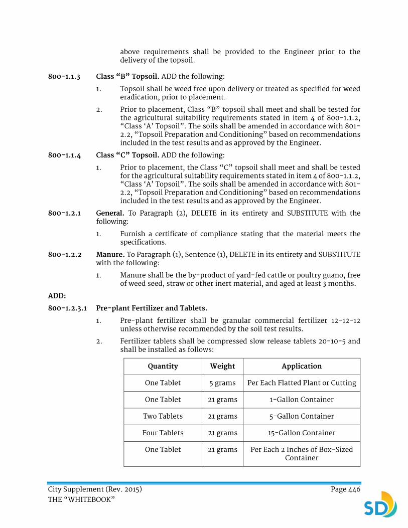
City Supplement (Rev. 2015) Page 446 THE “WHITEBOOK”
above requirements shall be provided to the Engineer prior to the delivery of the topsoil.
800-1.1.3 Class “B” Topsoil. ADD the following:
1. Topsoil shall be weed free upon delivery or treated as specified for weed eradication, prior to placement.
2. Prior to placement, Class “B” topsoil shall meet and shall be tested for the agricultural suitability requirements stated in item 4 of 800-1.1.2, “Class ‘A’ Topsoil”. The soils shall be amended in accordance with 801-2.2, “Topsoil Preparation and Conditioning” based on recommendations included in the test results and as approved by the Engineer.
800-1.1.4 Class “C” Topsoil. ADD the following:
1. Prior to placement, the Class “C” topsoil shall meet and shall be tested for the agricultural suitability requirements stated in item 4 of 800-1.1.2, “Class ‘A’ Topsoil”. The soils shall be amended in accordance with 801-2.2, “Topsoil Preparation and Conditioning” based on recommendations included in the test results and as approved by the Engineer.
800-1.2.1 General. To Paragraph (2), DELETE in its entirety and SUBSTITUTE with the following:
1. Furnish a certificate of compliance stating that the material meets the specifications.
800-1.2.2 Manure. To Paragraph (1), Sentence (1), DELETE in its entirety and SUBSTITUTE with the following:
1. Manure shall be the by-product of yard-fed cattle or poultry guano, free of weed seed, straw or other inert material, and aged at least 3 months.
ADD:
800-1.2.3.1 Pre-plant Fertilizer and Tablets.
1. Pre-plant fertilizer shall be granular commercial fertilizer 12-12-12 unless otherwise recommended by the soil test results.
2. Fertilizer tablets shall be compressed slow release tablets 20-10-5 and shall be installed as follows:
Quantity Weight Application
One Tablet 5 grams Per Each Flatted Plant or Cutting
One Tablet 21 grams 1-Gallon Container
Two Tablets 21 grams 5-Gallon Container
Four Tablets 21 grams 15-Gallon Container
One Tablet 21 grams Per Each 2 Inches of Box-Sized Container

City Supplement (Rev. 2015) Page 447 THE “WHITEBOOK”
ADD:
800-1.2.3.2 Post-plant Fertilizer.
1. Post-plant fertilizer shall be slow release 15-15-15 unless otherwise recommended by the soil test results.
800-1.2.5 Mulch. DELETE in its entirety and SUBSTITUTE with the following:
1. Mulch shall be designated by Type in accordance with the requirements herein.
2. Mulch shall be packaged in bales or bags unless the Engineer approves a bulk source in advance of delivery to the Work site.
3. Mulch materials shall be free of seed, debris, and deleterious materials as certified by the Supplier and shall be as follows:
a) Type 1 Mulch (ground wood product) shall conform to Type 1 organic soil amendment.
b) Type 2 Mulch (sewage sludge product) shall conform to Type 2 organic soil amendment.
c) Type 3 Mulch (mushroom compost) shall conform to Type 3 organic soil amendment.
d) Type 4 Mulch (peat) shall be brown compressed sphagnum or hypnum.
e) Type 5 Mulch (fir or redwood bark chips) shall be fir or redwood bark chips in the gradation specified.
f) Type 6 Mulch (straw) shall be either threshed new straw or stable bedding material derived from rice, oats or barley. Straw in an advanced state of decomposition shall not be acceptable.
g) Type 7 Mulch (wood chips) shall be wood chips in the size and type specified.
h) Type 8 Mulch (shredded redwood or cedar bark) shall be either redwood or incense cedar bark which knits in a manner to minimize sloughing, floating, or being kicked away.
i) Type 9 Mulch (recycled) shall be recycled and clean green material processed in accordance with California Code of Regulations, Title 14, Chapter 3, Article 7, §17868.3. Clean green material shall be tree and landscape materials that have never been mixed with other waste materials and have been processed by a permitted compost facility. Type 9 Mulch size shall be as specified in the Special Provisions.

City Supplement (Rev. 2015) Page 448 THE “WHITEBOOK”
j) Type 10 Mulch (rock, gravel, or cobble) shall be rock, gravel, or cobble in the size specified in the Contract Documents.
k) Type 11 Hydro-mulch (wood fiber) shall be of clean and natural non-recycled wood fibers processed to contain no germination or growth inhibiting factors using non-toxic dye to facilitate the metering of materials. Type 11 Hydro-Mulch shall be manufactured in such a manner that, after its addition to and agitation in slurry tanks with fertilizer, seed, water, stabilizing emulsion, and other approved additives, fibers in the material shall be uniformly suspended and shall form a homogeneous slurry. When hydraulically sprayed on the ground, the homogeneous slurry shall form a blotter-like ground cover impregnated uniformly with seed which shall allow moisture and rainfall to percolate to the underlying soil after application. Suppliers shall certify that their product meets all foregoing requirements based on testing.
l) Type 12 Hydro-mulch (stabilizing emulsion) shall be a concentrated liquid chemical that forms a plastic film upon drying and allows water and air to penetrate. The films shall be non-flammable and shall have an effective life of at least 1 year. Stabilizing emulsion shall be non-toxic to plant or animal life and non-staining to concrete or painted surfaces. In its cured state, the stabilizing emulsion shall not be re-emulsifiable. The material shall be registered with and licensed by the State of California, Department of Food and Agriculture, as an “Auxiliary Soil Chemical”.
m) Type 13 Hydro-mulch (bonded fiber matrix) shall be wood fiber, long strand, and whole wood fiber thermomechanically processed from clean whole wood chips. The fibers shall:
i. Disperse into a uniform slurry when mixed with water.
ii. Contain ¾ inch (19.1 mm) fiber strands for at least 25% by total volume.
iii. Be retained 100% when passed through a No. 25 sieve.
iv. Have an initial moisture content of no more than 15% of its dry weight when tested under CA Test 226. The moisture content shall be marked on the packaging.
v. Have a water holding capacity by weight of at least 1,200% when tested under the procedure designated in the Department's Final Report, CA-DOT-TL-2176-1-76-36, “Water Holding Capacity for Hydromulch”, available from METS.
vi. Be non-toxic to plant and animal life.
vii. Be free of synthetic or plastic materials, lead paint, printing ink, varnish, petroleum products, seed germination inhibitors, and chlorine bleach.
viii. Contain less than 250 ppm of boron.
City Supplement (Rev. 2015) Page 449 THE “WHITEBOOK”
ix. Contain less than 7% ash when tested under Technical Association of the Pulp and Paper Industry, TAPPI Standard T 413.
x. Be colored to contrast with the area on which the fiber is to be applied. The coloring agent shall be biodegradable, nontoxic, free from copper, mercury, and arsenic, and shall not stain concrete or painted surfaces.
The bonding agent for the fiber material shall be a liquid formulation with polyacrylamide as the primary active ingredient with the following requirements:
i. Linear, anionic copolymer of acrylamide and sodium acrylate.
ii. Anionic with a residual monomer content that is at most 0.05% by weight.
iii. Formulated and labeled as one of the following:
Water-in-oil emulsion containing at least 2.6 pounds of pure polyacrylamide per gallon (0.3 kg/L). Pure polyacrylamide shall be at least 30% active.
Liquid dispersed polyacrylamide containing at least 4.4 pounds pure polyacrylamide per gallon (0.5 kg/L). Pure polyacrylamide shall be at least 35% active.
ADD:
800-1.2.6 Inorganic Soil Amendments.
1. Iron sulfate shall be ferric or ferrous sulfate in pelleted or granular forms containing not less than 18% metallic iron. It shall conform to the Agricultural Code of the State of California.
2. Gypsum shall be commercially processed and packaged CaSo4 - 2H2O with a minimum 80% grade containing 14% minimum combined sulfur.
800-1.3 Seed. DELETE in its entirety and SUBSTITUTE with the following:
1. Seed shall be fresh, clean, new crop seed, and mechanically premixed to the specified proportions.
2. Seed shall be delivered to the Work site in original unopened containers bearing the dealer’s “Guaranteed Analysis”, germination percentage, and a certificate, stamp, or release by a County Agricultural Commissioner. Any seed tagged “Warning, Hold for Inspection” shall be inspected and released by the Agricultural Commissioner of the County within which the seeds are to be planted.
3. All seed used for lawn, erosion control, or other planting specified on the Plans or listed in the specifications shall be furnished in labeled and
City Supplement (Rev. 2015) Page 450 THE “WHITEBOOK”
sealed standard containers with duplicate signed copies of a statement from the vendor certifying that each container of seed delivered is fully labeled in accordance with the California State Agricultural Code stating the certified percent of purity and germination.
4. Seed which has become wet, moldy, or otherwise damaged in transit or storage shall not be accepted.
5. Custom seed blends shall have the Project name printed on the seed tag. Prior to the start of any seeding operation, custom seed blends shall be inspected and approved by the Engineer once delivered to the Site.
6. Unless otherwise specified, turf seed shall be one of the following or approved equal:
a) 20% Common Bermuda, 10% Hybrid Bermuda, 10% “Barclay” Perennial Rye, and 60% “Turfstar” Perennial Rye.
i. Seeds shall be hulled when applied from April to September.
ii. Seeds shall be unhulled when applied from October through March.
b) Agrono-tec Ballfield Mix 2A.
c) OreGro Sports Mix #2.
800-1.4.1 General. DELETE in its entirety and SUBSTITUTE with the following:
1. Plants shall be inspected and approved by the Engineer prior to planting at the time of arrival to the job site. Prior to 15 Days before installation, you shall submit photos of all proposed plants to be used in accordance with 2-5.3.4, “Supporting Information”.
2. Plants shall have a growth habit normal to the species and shall be sound, healthy, vigorous, and free from insect pests, plant diseases, sun scalds, fresh bark abrasions, excessive abrasions, or other objectionable disfigurements.
3. Tree trunks shall be sturdy and well “hardened off”.
4. Plants shall have normal well-developed branch systems and vigorous and fibrous roots systems which are neither root nor pot bound and are free of kinked or girdling roots.
5. Other than the normal side pruning during the growth period, pruning shall not be done prior to inspection at the nursery.
6. The scientific and common names of plants specified shall conform to the approved names given in the “Western Garden Book” published by Sunset Publishing, Menlo Park, CA.
7. When delivered on site, each group of plant materials shall be labeled clearly from the nursery source as to species and variety. Patented plants

City Supplement (Rev. 2015) Page 451 THE “WHITEBOOK”
(cultivars) required by the plant list shall be delivered with a proper plant patent attached. Any plants which are not labeled or are not as indicated on the Plans and Specifications shall be rejected and shall be removed from the site immediately.
800-1.4.2 Trees. ADD the following:
1. Trees shall have a uniform trunk taper from the base of the tree, continuing up the main leader. Palms shall be un-skinned unless specified otherwise.
2. Trees with naturally occurring central leaders shall remain un-pruned or unaltered from the nursery.
800-1.4.4 Flatted Plants. To Sentence (1), REVISE “flats” to “flat”.
800-1.4.5 Sod and Stolons (turf grass). ADD the following:
1. Sod and stolons species shall be as specified on the Plans or in the Special Provisions. Material shall be delivered and installed within 24 hours of harvesting with shipping documentation to verify the origin, harvest date, stolon preparation date, and shipment date. All material shall be from the same growing ground.
ADD:
800-1.4.7 Vines.
1. Vines shall be of the specified type and size.
800-1.5.3 Tree Stakes. DELETE in its entirety and SUBSTITUTE with the following:
1. The type of tree stake and length shall be as designated on the Plans or in the Special Provisions.
2. The tree support stakes shall be 10 feet (3 m) long.
ADD:
800-1.5.4 Tree Ties.
1. Tree ties shall be manufactured of virgin flexible vinyl meeting ASTM-D412 standards for tensile and elongation strength. Material shall be black or ultraviolet resistance.
2. Tree ties shall be manufactured with a double back locking configuration and secured with one galvanized nail to prevent slippage.
3. Tree ties shall elongate with the tree growth and shall prevent damage to the tree.
City Supplement (Rev. 2015) Page 452 THE “WHITEBOOK”
ADD:
800-1.6 Erosion Control Matting.
800-1.6.1 Jute.
1. Jute matting shall be of open weave with approximately 1 in2 (1 inch x 1 inch) (25.4 mm x 25.4 mm) mesh. It shall be manufactured from loosely twisted jute yarn varying in thickness no more than half its normal diameter.
2. Matting shall be made smolder resistant by treatment with chemicals which are non-leaching and non-toxic to vegetation. An identification mark to differentiate it from untreated jute cloth shall be present.
800-1.6.2 Excelsior.
1. Excelsior blanket shall consist of a cured wood excelsior mat.
2. Fibers shall be evenly distributed over the entire area of matting. 80% of fibers shall be at least 6 inches (152.4 mm) long with consistent thickness.
3. The topside of the matting shall be covered with 2 inch by 1 inch (50.8 mm x 25.4 mm) biodegradable extruded plastic mesh.
4. The blanket shall be made smolder resistant without chemical additives.
800-1.6.3 Staples.
1. Staples for erosion control matting shall be 11 gage steel wire bent in a “U” shape with 6 inches (152.4 mm) minimum length.
800-1.6.4 Root Barriers.
1. Root barriers shall be equivalent to the following:
a) Type LB 12-2 or UB 18-2 for installations at existing trees or approved equal.
b) UB 24-2 for installations at new construction, as manufactured by DeepRoot or approved equal.
c) 19.5 inch (495.3 mm) root control fabric as manufactured by Biobarrier, or approved equal.
800-2.1.3 Plastic Pipe for Use with Solvent Weld Socket or Threaded Fittings. ADD the following:
1. Schedule 40 or Class 315 pipe shall be used for continuously pressurized pipe on the supply side of control valves as shown on the Plans.
City Supplement (Rev. 2015) Page 453 THE “WHITEBOOK”
2. Schedule 40 pipe shall be used for installation on the discharge side of control valve. Schedule 80 shall only be supplied when threaded joints are specified or otherwise permitted by the Engineer.
3. Fittings and couplings for plastic pipe shall be threaded or slip-fitted tapered socket solvent weld type. Threaded female adapters shall be provided with socket pipe for connections to threaded pipe. Plastic pipefitting and coupling shall be PVC I or PVC I/II material. The type of plastic material and schedule size shall be indicated on each fitting or coupling. Fittings and couplings shall comply with the following table:
SCHEDULE SOCKET FITTING THREADED FITTINGS
40 ASTM D2466 ASTM D2466
80 ASTM D2467 ASTM D2464
ADD:
800-2.1.3.1 Pipe Primer and Glue.
1. Refer to 207-17.3.3, “Solvent Cement Joints”.
ADD:
800-2.1.3.2 Pipe Sleeves.
1. Pipe sleeves shall be Schedule 40 pipe and shall be 2 times the diameter of the pipe or wire bundle being sleeved. Pipe sleeves shall extend 12 inches (304.8 mm) beyond the edge of hardscape and shall be required when wires and pipes cross under streets, driveways, walkways, and access paths. Pull boxes shall be located over the terminus of the sleeve. At the end of the sleeve, wires shall extend up into the pull box and shall provide a 2 foot (0.6 m) expansion loop.
ADD:
800-2.1.6 Concrete Thrust Blocks.
1. Refer to 201-1.1.2, “Concrete Specified by Class and Alternate Class”.
800-2.2.3 Manual Control Valves. DELETE in its entirety and SUBSTITUTE with the following:
800-2.2.3 Manual Control Globe Valves.
1. Manual control globe valves shall be brass or bronze and shall be straight or angle pattern globe valves. Valves shall be full-opening, key-operated with a replaceable compression disc, and shall have ground joint unions on the discharge end.
800-2.2.4 Remote Control Valves. DELETE in its entirety and SUBSTITUTE with the following:
1. Remote control valves shall be:
a) Electrically or hydraulically operated.
b) Brass or bronze with accurately machined valve seat surfaces.
City Supplement (Rev. 2015) Page 454 THE “WHITEBOOK”
c) Equipped with flow control adjustment and capability for manual operation.
d) Made so that they may be readily disassembled for servicing.
2. Plastic remote control valves shall be electrically operated and may be used only when specified or with prior approval from the Engineer.
3. Unless otherwise specified, the valve body shall be constructed of heavy-duty glass-filled UV-resistant nylon and have stainless steel studs and flange nuts. Diaphragms shall be of nylon reinforced nitrile rubber with accurately machined valve seat surfaces equipped with flow control adjustments and shall be capable of manual operation. All internal parts shall be removable from the top of the valve without disturbing the valve installation.
800-2.2.6 Quick-Coupling Valves and Assemblies. DELETE in its entirety and SUBSTITUTE with the following:
1. Quick coupling valves shall be brass or bronze with self-closing valves and shall be supplied in 1 inch (25.4 mm) sizes, unless otherwise specified.
2. When a quick-coupler assembly is specified, it shall consist of the valve, quick-coupler connection and hose swivel.
3. Quick coupling valves shall have a locking rubber cap.
800-2.2.7 Valve Boxes. DELETE in its entirety and SUBSTITUTE with the following:
1. Valve boxes shall be constructed of precast concrete.
2. Covers shall be cast iron with a non-corrosive metal self locking device connected with stainless steel bolts and self locking nuts. Covers shall be permanently and legibly labeled with 100% acrylic epoxy white or yellow water proof paint on the top of the box indicating the component contained in the box.
3. A manufactured weatherproof plastic identification tag showing the irrigation controller and station shall be affixed to the colored conductor wire in each valve and pull box.
ADD:
800-2.2.8 Master Control Valve.
1. The master control valve shall be of a normally open design of solid brass construction with a waterproof 24 VAC 3-way solenoid coil, self-cleaning orifice, and one-piece molded construction diaphragm with an integral O-ring seal reinforced with 600 lb (272.2 kg) test fabric.

City Supplement (Rev. 2015) Page 455 THE “WHITEBOOK”
2. The master control valve shall be slow closing to prevent water hammer and surge and shall operate on pressures by valve size in accordance with the table below:
Operating Pressure (psi) Valve Size (Inch)
Up to 200 (1379 kPa) ¾ - 2 (19.1 mm – 50.8 mm)
150 (1034.2 kPa) 2½ - 3 (63.5 mm – 76.2 mm)
ADD:
800-2.2.9 Flow Sensing Device.
1. The flow sensing device shall be an in-line type with a non-magnetic, spinning impeller as the only moving part. The electronics housing shall be glass-filled. The impeller shall be glass-filled nylon or Tdfzel with a UHMWPE or Tefzel sleeve bearing. The shaft material shall be tungsten carbide. The electronics housing shall have two ethylene-propylene O-rings and shall be easily removed from the meter body.
2. The sensor electronics shall be potted in an epoxy compound designed for prolonged immersion. Electrical connections shall be 2 single conductor 18AWG leads. Insulation shall be direct burial “UF” type colored red for positive lead and black for the negative lead. The flow sensing device shall operate in line pressures up to 100 psi (689.5 kPa) and shall operate in flows of 1 foot per second (30.5 cm/sec) to 20 feet per second (609.6 cm/sec) with linearity of ±1% and repeatability of ±1%. The meter body shall be fabricated from Schedule 80 PVC tees with socket end connections.
ADD:
800-2.2.10 Flow Sensor Cable.
1. The flow sensor cable shall be 2 conductor 20 AWG shielded U.L. type PTLC wire rated to 105° C (221° F), per manufacturer’s specification. Maximum Wire run shall not exceed 2000 linear feet (609.6 m) from flow sensor to the irrigation controller.
2. Flow sensor data cable shall be installed in ¾ inch (19.1 mm) PVC conduit from controller to flow sensor.
ADD:
800-2.2.11 Rain Sensing Device.
1. The rain sensing device shall be constructed of high impact thermoplastic which shall withstand extreme weather conditions. The enclosure shall be stainless steel and vandal resistant. It shall contain hygroscopic discs which absorb water and expand proportionally to the amount of rain collected. Unless otherwise specified, the rain sensing device shall be connected to the controller and shall operate by interrupting the electrical circuit from the irrigation controller to the irrigation remote control valves and by restoring the electrical circuit upon sufficient drying of the hygroscopic discs.

City Supplement (Rev. 2015) Page 456 THE “WHITEBOOK”
ADD:
800-2.2.12 Locking Manual Valve Cap.
1. The locking manual valve cap shall be molded high-impact plastic body with locking brass hinged covers as manufactured by Weathermatic or approved equal.
ADD:
800-2.2.13 Pressure Regulating Valve.
1. The pressure regulating valve shall consist of a bronze body and bell housing, a separate access cover for the plunger and a bolt to adjust the downstream pressure. The bronze bell housing and access cap shall be threaded to the body and shall not require the use of screws. The assembly shall be of the balanced piston design and shall reduce pressure in both flow and no-flow conditions. The assembly shall be accessible for maintenance without having to remove the body from the water line.
ADD:
800-2.2.14 Wye Strainer.
1. The Wye Strainer shall be cast bronze per ASTM B584. The strainer screen shall be 20 mesh 300 series stainless steel and shall be accessible for cleaning without removing the device from the water line.
ADD:
800-2.2.15 Backflow Preventer Enclosure.
1. The backflow preventer enclosure frame shall be constructed of 1¼ inch (31.8 mm) tubular stainless steel with formed stainless steel tubing and rod or ½ inch (12.7 mm) #13 flattened mesh expanded stainless steel cage. The enclosure shall be smooth with no sharp edges or burrs. The enclosure shall be equipped with stainless steel mounting hardware and locking mechanism capable of being embedded into a concrete pad. The enclosure shall be of sufficient size to contain the backflow preventer and any ancillary equipment such that the inlet and outlet pipes shall be fully within the enclosure.
ADD:
800-2.2.16 Anti-drain Check Valve.
1. Anti-drain check valves shall be capable to compensate for elevation changes up to 32 feet (9.8 m) and shall meet Schedule 80 pipe specifications. The anti-drain check valves shall be capable of being adjusted through the top of the valve.
2. Anti-drain check valves shall be installed within the swing joint below the irrigation head unless the irrigation head specified has an integral anti-drain check valve or site conditions warrant additional protection as determined by the Engineer.

City Supplement (Rev. 2015) Page 457 THE “WHITEBOOK”
ADD:
800-2.2.17 Booster Pump.
1. The water pressure booster pump system shall be designed and fabricated by Barrett Engineered Pumps or approved equal. The system shall be a completely prefabricated system with pump, piping, and electrical and structural elements fully contained within a marine grade aluminum alloy enclosure with a hinged top. The enclosure shall be secured to the concrete pad with stainless steel hardware.
2. The pump shall be single stage end suction close-coupled centrifugal cast iron bronze fitted construction equipped with mechanical shaft seal and back pullout design. Impeller shall either be keyed or locked to the shaft with a hex head impeller nut and washer or shall be threaded directly to the end of the shaft. Pump shaft shall either be high strength S.A.E. 1045 carbon steel protected in the stuffing box area by a replaceable bronze shaft sleeve or shall be stainless steel with no sleeve. Pump shall be directly coupled to a C-face electric motor.
3. The electric motor shall be of the squirrel cage induction type suitable for full voltage starting. Motor shall be ODP to aid in cooling. Electric motor shall be rated for continuous service. The motor bearings shall be of such size that the average life rating is no less than 3 years (10,000 hours) of B10 life. The motor shall have horsepower ratings such that the motor shall carry the maximum possible load to be developed under the designed pumping conditions and not overload the motor beyond the nameplate rating of the motor. Motor shall have a 1.15 service factor. The motor shall conform to the latest NEMA Standards for motor design and construction.
4. The pump control panel shall have a NEMA 4X plain front non-metallic enclosure with padlock latches and shall include power and control resettable thermal circuit breakers, heavy duty magnetic starter with adjustable overload protection, Hand-Off-Auto switch to select mode of operation, and heavy duty numbered terminal strips for power and control wiring lead terminations.
5. The metal oxide varistor protected pump start relay(s) shall be incorporated in the panel to start the pump with a signal from each irrigation controller.
6. All system piping shall be type “L” copper. All fittings shall be copper or brass with unions or flanges to allow for system disassembly or major component removal. The system shall incorporate an integral full pipe size bypass line with a check valve to allow for pump removal and repair without disrupting water supply to system.
7. Isolation valves shall be all brass quarter turn ball valves with hard chrome ball on lines 2 inches (50.8 mm) and less. Isolation valves shall be lug style butterfly valves with Buna-N elastomeric seats, ductile iron nickel coated disc, and stainless steel stem with handle and 10 position galvanized memory plate on lines 2½ inches (63.5 mm)and greater.
City Supplement (Rev. 2015) Page 458 THE “WHITEBOOK”
8. Check valves shall be all brass spring loaded disc style with metal-backed Teflon wafer disc, stainless steel stem, and spring on lines 2 inches (50.8 mm) and less. Check valves shall be cast iron bronze fitted wafer style silent check with spring loaded bronze disc, bronze guide shaft, stainless steel spring, and replaceable bronze seat on lines 2½ inches (63.5 mm) and greater.
9. Gauges shall be 2½ inches (63.5 mm) diameter face, glycerin filled with stainless casing, and brass internals. Gauges shall be equipped with brass isolation petcocks.
10. The pump system shall have a flow activated paddle style magnetically coupled flow switch, sensitive to flows as low as 1 fps, mounted on piping and interconnected to time delay relay to shut down pump on no-flow conditions. The time delay relay shall be adjustable from 0 to 5 minutes.
11. Pump system shall be mounted on a structural aluminum skid with mounting flanges on front and back to allow for mounting of skid to concrete pad. The skid shall be equipped with pipe support on suction and discharge piping. All nuts, bolts, and washers shall be heavy zinc coated steel on skid and piping. Skid shall include mounting hardware for integral aluminum enclosure.
12. The enclosure shall be constructed of marine grade aluminum alloy 5052-H32 or minimum 14 gauge #304 stainless steel including the mounting base and fastening hardware with #4 polished finish. The system enclosure shall be vandal and weather resistant. The enclosure shall be low profile hinged top design with padlock provision. The cover shall be secured to the concrete pad with stainless steel hardware.
13. Power, low voltage, and plumbing connections shall be contained within the enclosure and shall be fully grounded (with grounding rod).
14. Unless specified otherwise, pump assembly shall include the following options:
a) Top of Form.
b) Hydraulically controlled, diaphragm actuated pressure-regulating valve, cast iron bronze trim with epoxy coated body, equipped with flow clean strainer option. Valve shall provide constant downstream pressure regardless of pump discharge pressure.
c) Low suction pressure switch mounted on suction manifold and interconnected to time delay relay adjustable from 0 to 5 minutes to shut down pump on low suction pressure.
d) High temperature non-adjustable thermostat mounted on pump discharge to shut down pump on heat buildup in pump casing due to no-flow situations. Set for 130° F (54.4° C).
e) Electrical current measurement control sensor switch mounted in control panel to shut down pump on loss of suction fluid or loss of prime.
City Supplement (Rev. 2015) Page 459 THE “WHITEBOOK”
15. A factory trained service professional shall be required on the site to certify proper installation, perform the startup, and instruct operating personnel. A startup report containing voltage and amperage readings, suction and discharge pressure readings, estimated flow conditions, and general operating characteristics shall be submitted to the Engineer.
16. Four (4) physical copies and 1 electronic copy of operating and maintenance manuals shall be provided to the Engineer after startup and shall include parts manuals for components, performance curves for pumps, general sequences of operations, and electrical schematics for control panels.
800-2.3 Backflow Preventer Assemblies. ADD the following:
1. Include the installation of backflow preventer enclosures in accordance with 800-2.2.15, “Backflow Preventer Enclosure”.
800-2.4 Sprinkler Equipment. DELETE in its entirety and SUBSTITUTE with the following:
1. Sprinkler heads, bubbler heads, and spray nozzles shall be of the types and sizes shown on the Plans. Equipment of one type and flow characteristics shall be from the same manufacturer and all equipment shall bear the manufacturer’s name and identification code in a position where they can be identified in the installed position.
2. Fixed heads, shrubbery heads, and bubbler heads shall have adjustable radius control.
ADD:
800-2.4.1 Low Flow Irrigation Equipment.
800-2.4.1.1 Pressure Regulator.
1. Pressure regulators shall be preset in line regulators set not to exceed the manufacturer’s pressure rating of the emitter head or drip tubing. Pressure regulators shall be constructed of high-impact thermoplastic with fixed stainless steel compression spring housed in separate chamber from the normal water flow. The size shall be as specified on the Plans.
800-2.4.1.2 Filter.
1. Filters shall be provided in each valve servicing low flow irrigation systems. The filter shall be line-size with 2 piece threaded housing with O-ring seal molded from high heat. The filter shall be chemical resistant ABS plastic and shall have a ball flush valve connected. The filter screen shall be stainless steel with 150 mesh size (100 Micron) with the collar molded from vinyl.

City Supplement (Rev. 2015) Page 460 THE “WHITEBOOK”
800-2.4.1.3 Air Relief Valve.
1. The air relief valve shall be located at the highest end of each lateral for low flow irrigation systems. Air relief valve shall be manufactured from non-corrosive material with ½ inch (12.7 mm) male pipe thread. Maximum operating pressure shall be 100 psi (690 kPa).
800-2.4.1.4 Flush Valve.
1. Flush valve shall automatically operate at the start of each irrigation cycle. The flushing water volume shall be 1 gallon (3.8 L) per cycle.
800-2.4.1.5 Drip Emitter.
1. The emitters shall uniformly regulate the water discharged from each port at the rate specified on the plans. The emitter shall be multi-outlet made of UV resistant polymer and resistant to impact and high temperature. Unless otherwise specified, the emitter shall have a minimum of 6 independent barbed outlet ports that are mounted on the bottom of the device and that securely retain ¼ inch (6.4 mm) distribution tubing. The body shall have a ½ inch (12.7 mm) female pipe thread connection.
800-2.4.1.6 Drip Tubing.
1. The distribution drip tubing shall be constructed from UV resistant polyethylene materials. The drip tubing shall be secured with 4 inch (101.6 mm) minimum length tubing stake and constructed of UV-resistant plastic material sized to accommodate the drip tubing. Tubing shall be installed with protective distribution cap (Bug Cap). Bug Cap shall have a barb inlet and a flanged shield. The barb inlet shall fit into ¼ inch (6.4 mm) distribution tubing with ID of 0.16 inches (4.1 mm). The flanged shield of the Bug Cap shall diffuse water to minimize soil erosion at emission point. The Bug Cap shall be made of polyethylene.
2. Drip tubing shall conform to the following:
a) ¼ inch (6.4 mm) tubing designed for use with all drip systems.
b) Wall thickness shall be 0.04 inch (1 mm).
c) 60 psi (413.7 kPa) rating.
d) Compatible with all ¼ inch (6.4 mm) transfer fittings and all barbed outlet ports.

City Supplement (Rev. 2015) Page 461 THE “WHITEBOOK”
ADD:
800-2.5 Extra Equipment to Be Furnished.
1. You shall provide the following to the City prior to the final Acceptance, unless otherwise specified on the Plans or Special Provisions:
a) Five (5) irrigation heads with nozzles of each type used for every 100 irrigation heads or portions thereof.
b) Two (2) sets of special tools required for removing, disassembling, and adjusting each type of sprinkler and valve supplied on the project.
c) Two (2) sets of 5 foot (1.5 m) valve keys for every 20 gate valves installed or portions thereof.
d) Two (2) sets of keys for each automatic controller, locking valve box, and locking quick coupler.
e) Two (2) sets of keys for each pump.
f) Two (2) sets of valve keys for every 20 quick coupler assemblies installed or portions thereof.
800-3.2.1 Conduit. DELETE in its entirety and SUBSTITUTE with the following:
1. Rigid non-metallic conduit shall conform to the requirements of the UL Standard for Rigid Non-Metallic Conduit, Publication UL 651 (PVC Schedule 80) and UL 651B (HDPE). Rigid non-metallic conduit connections shall be of the solvent weld type. For underground installation, conduit shall be UL approved heavy wall polyvinyl chloride (PVC Schedule 40) unless specified otherwise on the Plans or Special Provisions.
800-3.2.2 Conductors. ADD the following:
1. #14 AWG control wires shall be color coded per station as follows:
a) 1/19 Yellow
b) 2/20 Orange
c) 3/21 Blue
d) 4/22 Black
e) 5/23 Brown
f) 6/24 Purple
g) 7 Yellow w/ Black stripe
h) 8 Orange w/ Black stripe
i) 9 Red w/ Black stripe

City Supplement (Rev. 2015) Page 462 THE “WHITEBOOK”
j) 10 White w/Red stripe
k) 11 Yellow w/Red stripe
l) 12 Blue w/ Red stripe
m) 13 Orange w/ Red stripe
n) 14 Purple w/ White stripe
o) 15 Brown w/ White stripe
p) 16 Yellow w/ White stripe
q) 17 Blue w/ White stripe
r) 18 Red w/ White stripe
2. Spare Wires: (Red) #14 AWG. 2 spare wires shall be provided from each of the furthest manifolds in each direction to the controller and shall loop into a minimum of 1 valve box of each manifold along the wire run to the controller.
3. Common Wires: (White) #12 AWG.
4. Wire Bundles: Tape wire bundles with colored vinyl electrical tape 10 feet (3 m) OC. Use different color tape for each controller.
ADD:
800-3.2.2.1 Wire Connectors.
1. Wire connectors for direct burial irrigation control wires of 30 volts or less shall be capable to accommodate #18, #14, #12 and #10 gauge wire sizes and shall be designed to ensure waterproof connections. The wire connector kit shall contain a UL and CSA listed copper crimp sleeve, polyethylene connector body, and polyethylene connector plug. The connector plug shall be filled with blue color self-curing epoxy resin sealant immediately prior to assembly of the wire connector to fully waterproof the connection.
2. Wire connectors shall be installed in accordance with the manufacturer’s recommendations. Wires shall be crimped and soldered together and inspected by the Engineer prior to placement into the wire connector plug and sealant.
3. Wire in pull boxes shall be loose and shall not come within 3 feet (0.9 m) from the lid. Boxes shall be sized accordingly to accommodate this requirement.
ADD:
800-3.2.2.2 Wire Solder.
1. Wire solder shall be 60% tin and 40% lead alloy wire with internal flux capable of quickly turning from a solid state to a liquid state when heated and capable of quickly returning to a solid state upon cooling.
City Supplement (Rev. 2015) Page 463 THE “WHITEBOOK”
ADD:
800-3.2.2.3 Trench Marker Tape.
1. Trench marker tape shall be installed in accordance with Standard Drawing SDM-105, “Warning/Identification Tape Installation”.
ADD:
800-3.4 Pull Boxes Materials.
1. Pull boxes shall be constructed of precast concrete.
2. Covers shall be cast iron with a non-corrosive metal self-locking device, connected with stainless steel bolts and self-locking nuts, and permanently and legibly labeled as “PB” with the controller designation on the top of the cover. Use 100% acrylic epoxy white or yellow water proof paint for the labeling.
3. A manufactured weatherproof plastic identification tag showing the irrigation controller and station shall be affixed to the colored conductor wires in each pull box.

City Supplement (Rev. 2015) Page 464 THE “WHITEBOOK”
SECTION 801 - INSTALLATION
801-1 GENERAL. DELETE in its entirety and SUBSTITUTE with the following:
1. This section includes specifications for the preparation, planting, and irrigation system construction for landscape areas shown on the Plans.
2. Unless otherwise specified, walls, curbs, planter boxes, walks, irrigation systems, and similar improvements shall be constructed following rough grading and before landscaping.
3. Work on the irrigation system including hydrostatic tests, backfill and densification of trenches, and other excavations shall be performed before topsoil placement. Preliminary operational tests of the automatic control system and coverage tests shall be performed after top soil placement.
4. Trees or shrubs which have been identified to remain as shown on the Plans shall be protected. Construction fencing minimum 5 feet (1.5m) high shall be placed around the drip line of the tree or cluster of trees to protect the entire area. No material shall be stored nor shall equipment be permitted within the fenced area. Pruning of the tree canopy shall not be permitted without written recommendation of a certified arborist submitted and approved by the Engineer. Digging or excavation shall not occur under the drip line of the tree unless authorized by the Engineer. Failure to properly protect the identified trees may result in charges based on the assessed value of the tree and other damages once valued by a certified arborist.
801-2.1 General. ADD the following:
1. The subgrade soil below the proposed topsoil shall be scarified in a cross pattern to a depth of 3 inches (76.2 mm) for subgrade for Class A or B topsoil. Stones over 1 inch (25.4 mm) in greatest dimension shall be removed from the scarified area. The subgrade depth shall be verified by the Engineer prior to topsoil import.
801-2.2.1 General. DELETE in its entirety and SUBSTITUTE with the following:
1. Planting areas shall be free of weeds and other extraneous materials to a depth of 10 inches (254 mm) below finish grade before topsoil Work.
2. Soil shall not be worked when it is so wet or so dry as to cause excessive compaction or the forming of hard clods or dust.
3. Class “C” topsoil shall be scarified and cultivated to a finely divided condition to a depth of 8 inches (203.2 mm) minimum below finish grade. During this operation, all stones over ½ inches (12.7 mm) in greatest dimension shall be removed.
4. Unless otherwise specified on the Plans or Special Provisions, the topsoil shall be Class A and shall be 15 inches (381 mm) thick.
City Supplement (Rev. 2015) Page 465 THE “WHITEBOOK”
5. The soil shall be prepared in accordance with the recommendations of the soil analysis results stated in 800-1.1.2, “Class ‘A’ Topsoil”.
6. If leeching is required per the recommendations of the soil analysis results, amendments shall be blended into the soil prior to leeching. Leeching shall be performed until analysis results are in compliance with agriculture suitability standards.
7. After compaction, topsoil shall be within ± 0.1 foot (0.3 m) of finish grade.
801-2.2.2 Fertilizing and Conditioning Procedures. DELETE in its entirety and SUBSTITUTE with the following:
1. The planting area shall be brought to finish grade before spreading the soil amendment materials specified.
2. Soil amendment materials shall be uniformly spread at the prescribed rate as recommended in the soil test results.
3. The quantities of materials necessary for the planting area shall be at the Work site and verified by delivery tickets furnished to the Engineer before spreading.
4. After spreading, the soil amendments shall be cultivated into the upper 15 inches (381 mm) of soil by suitable equipment operated in at least 2 directions at right angles.
5. The resulting soil shall be in a friable condition.
6. All planting areas shall be fertilized in a uniform manner at the application rate identified in the soil analysis recommendations.
7. Fertilization of turf areas shall be accomplished by uniformly spreading 50% of the specified quantity in one direction. The remaining 50% of the fertilizer quantity shall be spread perpendicular to the previous direction, immediately after the initial application. Each of the applications shall be spread uniformly in parallel, overlapping passes, to provide uniform results.
801-2.3 Finish Grading. DELETE in its entirety and SUBSTITUTE with the following:
1. The finish grade shall be smooth, uniform, and free of abrupt grade changes and depressions to ensure surface drainage.
2. The finish grade adjacent to paving, curbs, or headers shall be ½ inch (12.7 mm) in lawn areas and 2 inches (50.8 mm) in shrub or groundcover areas.
3. The soil shall be watered and allowed to settle to provide a stable surface. After the soil has dried out to a workable condition, the planting areas

City Supplement (Rev. 2015) Page 466 THE “WHITEBOOK”
shall be regraded, raked, and smoothed to the required grades and contours.
4. Topsoil shall be mechanically compacted to a minimum relative compaction of 85%. Finish surfaces shall be clean and suitable for planting.
801-3 HEADER INSTALLATION. To Paragraph (2), DELETE in its entirety.
801-4.1 General. DELETE in its entirety and SUBSTITUTE with the following:
1. The types, sizes, and quantities of plant materials shall be as specified in the Special Provisions or shown on the Plans.
2. All plants shall be reviewed and approved prior to planting, including plants previously approved at the nursery. You shall be responsible for the condition of all plants, planted or otherwise, until the completion of the Work.
3. Planting shall be performed with materials, equipment, and procedures favorable to the optimum growth of the plants and in compliance with these procedures.
4. Except as noted for specimen planting, all planting shall follow the completion of the irrigation system.
5. Soil shall be fertilized prior to planting per the recommendations of the soil analysis results.
6. Application of the herbicides shall be as specified in the Special Provisions.
801-4.2 Protection and Storage. ADD the following:
1. Sun sensitive plants, stolons, and sod shall be stored in the shade or screened from the sun.
801-4.3 Layout and Plant Location. DELETE in its entirety and SUBSTITUTE with the following:
1. Prior to planting, perform a detailed layout within the planting areas to be approved by the Engineer.
2. The first row of plants in areas designated for center-to-center spacing of plants shall be located at one-half of designated spacing form the edge of the area unless specified otherwise on the Plans or Special Provisions.
3. Plants shall be located to prevent irrigation blockage.
City Supplement (Rev. 2015) Page 467 THE “WHITEBOOK”
801-4.5 Tree and Shrub Planting. DELETE in its entirety and SUBSTITUTE with the following:
1. Planting holes shall be the depth of and twice the width of the plant container or ball and shall be larger, if necessary, to permit handling and planting without injury or breakage of the root ball or root system. Any plant with a broken or cracked root ball before or during planting shall not be planted.
2. Containers shall be removed in such a manner that the roots are not injured. Balled plant wrappings shall be loosened or cut back after the plant is positioned in the planting hole.
3. The native soil at the bottom and sides of planting holes shall be scarified.
4. Prepared backfill mix for shrub planting shall consist of 20% to 40% by volume of Type 1, 2, or 3 organic soil amendments mixed with native soil, depending on soil conditions at each site, as approved by the Engineer. On projects requiring soil analysis of native soil, backfill mix shall be determined by the recommendation of the soil analysis results and as approved by the Engineer.
5. Planting installation shall conform to the following requirements:
a) The bottom of the planting pit shall be compacted.
b) The plant shall be set at the approximate center of the hole and plumb so that the crown of the plant is 1 inch (25.4 mm) above finish grade.
c) Backfill shall be added in 6 inch (152.4 mm) lifts and shall be hand tamped to finish grade.
d) The backfill shall be thoroughly water-settled and additional backfill added to fill any remaining void below finish grade.
e) After the water has drained, the specified number of fertilizer tablets shall be placed in the planting hole in the presence of the Engineer.
f) A circular watering basin slightly larger than the planting hole, 4 inches (101.6 mm) high shall be left around the plant. The bottom of the basin shall be at approximate finish grade or slightly lower. Type 1, 5, 10, or 13 mulch shall be spread at least 2 inches (50.8 mm) thick in the basin leaving 3 inches (76.2 mm) of clearance around the base of the tree or shrub.
6. Basins of planted container material shall not be planted or seeded.
7. After planting, the plant shall be plumb, with the root crown 1 inch (25.4 mm) above finish grade.

City Supplement (Rev. 2015) Page 468 THE “WHITEBOOK”
801-4.6.1 Method “A” Tree Staking. DELETE in its entirety and SUBSTITUTE with the following:
801-4.6.1 Tree Staking.
1. The tree shall be staked with the type and length of stake specified on the Plans or in the Special Provisions.
801-4.6.2 Method “B” Tree Staking. DELETE in its entirety and SUBSTITUTE with the following:
801-4.6.2 Guying.
1. Guying shall be done as specified on the Plans or in the Special Provisions.
801-4.6.3 Guying. DELETE in its entirety.
801-4.7 Ground Cover and Vine Planting. DELETE in its entirety and SUBSTITUTE with the following:
1. Soil preparation and fine grading shall be completed prior to ground cover planting.
2. Ground cover and vines shall be planted in moist soil and spaced as indicated on the Plans. Soil shall be moist within the total root zone of the material being planted.
3. Each plant shall be planted with its proportionate amount of container soil to minimize root disturbance. Soil moisture shall be such that the soil does not crumble when removing plants.
4. Following planting, ground cover and vine areas shall be regarded to restore smooth finish grade and to ensure proper surface drainage. A 2 inch (50.8 mm) layer of the specified mulch shall be spread over the planted areas unless specified otherwise.
5. When necessary to prevent plant damage from pedestrian traffic during the initial growing stage, erect temporary protective fencing to be removed at the end of the Plant Establishment Period.
6. Vines shall be tied to walls, fences, etc., in the manner prescribed in the plans.
801-4.8.2 Seed. ADD the following:
1. Turf Seed application rate shall be 10 lbs per 1000 square feet.
To Paragraph (2), subsection “a”, “Method A”, ADD the following:
The soil shall be moist for a depth of 6 inches (152.4 mm) before planting. If not, prior to planting the soil shall be watered to a depth of 8 inches (203.2 mm) and

City Supplement (Rev. 2015) Page 469 THE “WHITEBOOK”
allowed to dry out to the point soil is moist and shall support labor and equipment without damage or undue compaction to soil and finish grade.
To Paragraph (4), subsection “b”, “Method B”, DELETE in its entirety and SUBSTITUTE with the following:
b) Method B. The seed, fertilizer, fiber, and other materials in the slurry mixture shall be as specified in the Special Provisions or shown on the Plans. All materials shall be of such character that they shall disperse into a uniform slurry when mixed with water. The mixture shall be such that an absorbent and porous mat shall be formed. All materials shall be available for inspection prior to application. Weights and contents of containers shall be clearly identified. A green coloring additive shall be used in the slurry for visual inspection purposes. The slurry shall be applied under pressure at the specified rates. Areas to be planted by this method shall be moistened to a depth of 6 inches (152.4 mm). The slurry planted areas shall be kept moist during the germination period, but ponding shall be avoided.
i. Application Rates for Type 11 (Wood Fiber) Mulch. When specified, Apply Type 11 (Wood Fiber) Mulch in the locations, rates, and number of applications shown in the Contract Documents and as follows:
Apply in successive passes as necessary to achieve the required application rate. Form a continuous uniform mat with no gaps between the mat and the soil surface.
Apply in two or more directions.
Mulch application rate shall be 2000 lbs per acre.
Binder application rate shall be 150 lbs per acre.
Fertilizer application rate shall be in accordance with the soil analysis recommendations, unless otherwise specified.
Seed application rate and type shall be specified in the Contract Documents and/or as specified by the Project Biologist, when applicable.
ii. Application Rates for Type 13 Hydro-mulch (bonded fiber matrix). When specified, Apply Type 13 Hydro-mulch (bonded fiber matrix) in the locations, rates, and number of applications shown in the Contract Documents and as follows:
Apply in successive passes as necessary to achieve the required application rate. Form a continuous uniform mat with no gaps between the mat and the soil surface.
Apply in two or more directions.
Mulch application rate shall be 3500 lbs (including the binder) per acre, unless specified otherwise.

City Supplement (Rev. 2015) Page 470 THE “WHITEBOOK”
Fertilizer application rate shall be in accordance with the soil analysis recommendations, unless otherwise specified.
Seed application rate and type shall be specified in the Contract Documents and/or as specified by the Project Biologist, when applicable
801-4.8.3 Sod. To Paragraph (2), DELETE in its entirety and SUBSTITUTE with the following:
Subgrade for sod shall be the specified thickness of the sod below finish grade. Soil preparation and fine grading shall be completed before sodding. No heavy equipment shall operate over the subgrade after grading is completed. Sod shall be installed within 24 hours after cutting. Sod delivered which is reinforced with poly-netting shall be removed during installation.
To Paragraph (5), DELETE in its entirety and SUBSTITUTE with the following:
The area shall then be watered thoroughly to penetrate the subgrade at least 6 inches (152.4 mm). Watering shall be repeated as necessary to keep the sod moist until rooted into the subgrade. Sodded areas shall be protected against foot traffic through the Plant Establishment Period.
801-4.8.4 Stolon Planting. DELETE in its entirety and SUBSTITUTE with the following:
1. Topsoil preparation and finish grading shall be completed before stolon planting.
2. The area to be planted in stolons shall be thoroughly irrigated to a depth of at least 6 inches (152.4 mm) before planting. As soon as the soil can be worked, the specified commercial fertilizer shall be worked into the top 1 inch (25.4 mm) of soil.
3. At the time of planting, the top 2 inches (50.8 mm) of soil shall be friable and shall contain enough moisture to prevent stolons from drying out during the planting operation. The stolons shall be worked into the soil to a depth of ½ inch to 1½ inches (12.7 mm to 38.1 mm) by a mechanical or hand planter, or broadcast by hand and covered with ¼ inch (6.4 mm) of mulch.
4. When the area to be planted exceeds 10,000 ft2 (929 m2), a mechanical spreader shall be used. When less than 10,000 ft2 (929 m2) and more than 2,000 ft2 (185.8 m2), the use of a hand planter or mechanical planter is optional. When less than 2,000 ft2 (185.8 m2), hand planting or broadcasting with mulch is optional.
a) Hydrostolonization Application Rate.
i. Stolons shall be of the variety specified in the Contract Documents and shall be applied at a rate of 5 US bushels per 1000 square feet.

City Supplement (Rev. 2015) Page 471 THE “WHITEBOOK”
ii. Mulch shall be applied at a rate of 2000 lbs per acre.
iii. Fertilization application rate shall be as recommended in the soil analysis recommendations, unless specified otherwise.
5. The planted stolons shall not be allowed to dry out. Watering shall begin immediately after planting and the stolons shall be kept moist at all times throughout the Plant Establishment Period.
6. When overseeding is required, the seed shall be spread as shown on the Plans.
801-5.1 General. To Paragraph (2), DELETE in its entirety and SUBSTITUTE with the following:
You shall be responsible for furnishing the labor and materials for the utility connections. Utility connections shall be as shown on the Plan or designated by the utility company.
To Paragraph (3), ADD the following:
The installation of the irrigation system shall be in accordance with the manufacturer’s instructions unless specified otherwise.
801-5.2 Trench Excavation and Backfill. DELETE in its entirety and SUBSTITUTE with the following:
1. Trenches and other excavations shall be sized to accommodate the irrigation system components, conduit, and other required facilities. Additional space shall be provided to assure proper installation and access for inspection.
2. Unless otherwise specified, the minimum depth of cover over pipelines, sleeves, and conduits shall be as follows:
a) Electrical conduit – 18 inches (457.2 mm)
b) Water lines continuously pressurized – 21 inches (533.4 mm). Modify to 36 inches (914.4 mm) when under paved areas accessible by vehicles.
c) Lateral sprinkler lines – 15 inches (381 mm)
3. The bottom of trenches shall be true to grade and free of protruding stones, roots, or other matter which would prevent proper bedding of pipe or other facilities.
4. Trenches and excavations shall be backfilled so that the specified thickness of topsoil is restored to the upper part of the trench. Backfill shall be jetted in accordance with 306-12.4, “Jetted Trench Backfill”. Other methods of compacting backfill may be approved by the Engineer.

City Supplement (Rev. 2015) Page 472 THE “WHITEBOOK”
801-5.3.1 General. To Paragraph (2), Sentence (2), DELETE in its entirety and SUBSTITUTE with the following:
The pipe shall be surrounded with SE 50 plaster or mortar sand material per 200-1.5.5, “Sand Gradations”.
To Paragraph (3), ADD the following:
Irrigation mainlines, valves, and supporting equipment shall be located in the planting areas. Unless otherwise specified no parallel pressure pipelines shall be installed within 1 foot (0.3 m) of each other.
801-5.3.2 Steel Pipeline. To Paragraph (3), DELETE in its entirety and SUBSTITUTE with the following:
Joints shall be made with a non-toxic and non-hardening joint compound or Teflon tape and applied to the male threads only.
801-5.3.3 Plastic Pipeline. ADD the following:
1. Tees shall be installed horizontally at the connection with the main line.
801-5.3.4 Copper Pipeline. ADD the following:
1. Copper pipe shall have a straight butt square edge with all burrs and fins removed.
801-5.4 Installation of Valves, Valve boxes, and Special Equipment. DELETE in its entirety and SUBSTITUTE with the following:
1. All irrigation equipment, except sprinkler heads and bubblers, shall be located a minimum of 10 feet (3 m) away from all tree locations. All irrigation equipment, except sprinkler heads and bubblers, shall be placed in shrub beds unless otherwise specified.
2. Valves and other equipment shall be installed in a normal upright position unless otherwise recommended by the manufacturer, and shall be readily accessible for operation, maintenance, and replacement.
3. Valves shall be the same size as the pipeline in which they are to serve unless otherwise shown on the Plans.
4. Isolation valves shall be installed at line depth and shall be equipped with a sleeve centered on the valve stem. 2 inch (50.8 mm) and smaller globe valves shall be in PVC sleeves with locking metal lids. 2½ (63.5 mm) inch and larger isolation valves shall be in a 6 inch (152.4 mm) PVC sleeve centered in a locking valve box in accordance with 800-2.2.7, “Valve Boxes”.
5. Quick coupler valves projecting above grade shall be 12 inch (304.8 mm) from curbs, pavement and walks. In ground cover and shrubbery areas, quick coupler valves shall be set 2 inches to 3 inches (50.8 mm – 76.2 mm) above finish grade. Quick couplers in lawn areas shall be installed at finish grade.
City Supplement (Rev. 2015) Page 473 THE “WHITEBOOK”
6. Valve boxes and pipe sleeves with caps shall be set to finish grade.
7. Backflow preventers shall be provided with pipe supports and the accessories necessary to properly secure the assembly.
801-5.5.1 General. DELETE in its entirety and SUBSTITUTE with the following:
1. Mains and laterals, including risers, shall be flushed and pressure tested before installing swing joints and sprinkler heads, after which a water coverage test shall be performed.
801-5.5.2 Location, Elevation, and Spacing. DELETE in its entirety and SUBSTITUTE with the following:
1. Sprinkler head spacing shall not exceed the maximum shown on the Plans or recommended by the manufacturer.
2. In new lawn areas, sprinkler heads shall be installed 3 inches (76.2 mm) above grade and then reset flush with the finish surface just prior to the first mowing. Lawn sprinklers shall be installed 6 inches (152.4 mm) clear of adjacent walks, curbs, paving, headers, and similar improvements, unless otherwise specified.
3. Sprinkler heads shall be installed 24 inches (609.6 mm) from adjacent vertical elements projecting above grade such as walls, planter boxes, and fences.
4. Shrub heads, bubbler heads, and oscillating sprinklers shall be installed 12 inches (304.8 mm) above finish grade, unless otherwise specified.
5. Nozzle lines projecting above finish grade shall be at least 6 inches (152.4 mm) from adjacent curbs, walk, paving, and similar improvements.
801-5.5.3 Riser and Nozzle Line Installation. DELETE in its entirety and SUBSTITUTE with the following:
801-5.5.3 Riser Installation.
1. Risers shall be oriented perpendicular to finish grade and shall be Schedule 80 PVC.
2. Sprinkler head risers shall be installed as shown on the Plans.
801-5.5.4 Sprinkler Head Adjustment. DELETE in its entirety and SUBSTITUTE with the following:
1. When all sprinkler heads are installed and the irrigation system is operating, each irrigation station shall be adjusted, with control valves fully open, to obtain “head-to-head” irrigation coverage.
2. A water audit of the irrigation system shall be required as specified in the Special Provisions. Sprinkler heads having adjustable pin nozzles or orifices shall have the pins adjusted to a maximum 25% radius reduction to provide uniform distribution of water over the coverage area. Non-
City Supplement (Rev. 2015) Page 474 THE “WHITEBOOK”
adjustable sprinkler nozzles may require substitutions of smaller or larger nozzle cores as directed by the Engineer.
801-5.6 Automatic Control System Installation. DELETE in its entirety and SUBSTITUTE with the following:
1. You shall install a complete automatic irrigation control system including the automatic controller, remote control valves and wiring, and all necessary accessories and utility service connection.
2. The installation of the automatic controller shall be certified by the manufacturer upon the completion of installation. The automatic controller shall be installed outside of the coverage pattern of the irrigation system at the location shown on the Plans. Each controller shall have a power ON/OFF switch, with lock-out and tag-out capability and shall have a separate circuit breaker. The foundation for the controller shall be concrete, as specified in 201-1, “Portland Cement Concrete”, of the size shown on the Plans or recommended by the manufacturer. The control components in the controller shall be fused and the chassis shall be grounded. Remote control valves shall be compatible with the automatic controller.
3. For the purpose of these specifications, service shall include all material and equipment necessary to complete the electrical connection between the terminating point of the serving utility and the irrigation controller. A separate disconnect switch and circuit breaker shall be installed between the source of power and the controller. The minimum service wire shall be No. 12 AWG copper 600 volt type TW, TWH or TWHH or larger as required by the Contract Documents or controller manufacturer. Wire splices shall be located only in specified pull boxes and shall be made with a packaged waterproof kit approved for underground use. Pull boxes shall be set on an un-mortared brick foundation to finish grade in lawn areas and 2 inches (50mm) above finished grade in mulch areas.
4. Control wiring shall be color coded in accordance with 800-3.2.2, “Conductors”. Unless otherwise specified, all control wiring shall be direct burial, Type UF, No. 14 AWG copper. At least 2 feet (0.6 m) of slack shall be left at each splice and point of connection in pull boxes and valve boxes. Wire splices shall be located in specified pull boxes spaced at maximums of 300 feet (91.4 m).
5. All wiring shall be tested for continuity, open circuits, and unintentional grounds prior to connecting to equipment. The minimum insulation resistance to the ground shall be 50 megaohms. In multiple controller installations, the common control wires shall be separate for each controller. Multiple controller enclosures shall be sized accordingly. 110 volt wire runs shall not pass from controller to controller. Each controller shall have a separate electrical service and circuit breaker through an individual raceway.
6. Upon completion of the Work, a legible reduced copy of the As-Built irrigation Plans provided by the Engineer shall be color coded by

City Supplement (Rev. 2015) Page 475 THE “WHITEBOOK”
irrigation station, laminated in plastic, and placed on the inside of each controller enclosure. The outside of each controller enclosure shall be identified per the Plans with a black, permanent 2 inch (50.8 mm) stencil. The location of the controller identification shall be as approved by the Engineer. The color coded operational chart shall include the location of the circuit breaker and water meter feeding the controller. Each installed remote control valve shall be color coded to its parent controller.
801-5.7.2.1 General. DELETE in its entirety and SUBSTITUTE with the following:
1. Pressure testing for leakage shall be performed on newly installed supply lines, pressure mains, and laterals, except for non-ridged pipelines and pipelines with spray nozzles installed into the pipe. Pressure mains shall be tested with all control valves open and outlet side of valves capped.
2. Pipelines installed by trenching and backfilling and pipelines which are completely visible after installation shall be tested in accordance with 801-5.7.2.2, “Pipeline Pressure Test Method”.
801-5.7.2.2 Method A. DELETE in its entirety and SUBSTITUTE with the following:
801-5.7.2.2 Pipeline Pressure Test Method.
1. Pressure testing for leakage shall conform to the following procedure:
a) Notify the Engineer at least 24 hours prior to performing a pressure test. Pressure tests shall be performed such that the test periods are within the working hours specified in the Special Provisions. The Engineer shall observe each pressure test.
b) Before any portion of the pipeline on the supply side of a control valve is backfilled, water shall be turned into that portion of the line and maintained at full pressure as described in the table below from the water source for a period of not less than 4 consecutive hours after air has been expelled from the line. Before any portion of the pipeline on the discharge side of control valve is backfilled, a similar test shall be performed, except the test shall be for a period of 2 hours as described in the table below. Leaks that develop in a tested portion of the system shall be repaired. After the leaks have been repaired, the pressure test shall be repeated and additional repairs made until no leaks occur.
c) The constant test pressure shall be as follows:
Pressurized Mains 125 psi (861.8 kPa) 4 hours
Non-pressurized Laterals 100 psi (689.5 kPa) 2 hours
City Supplement (Rev. 2015) Page 476 THE “WHITEBOOK”
801-5.7.2.3 Method B. DELETE in its entirety.
801-5.7.3 Sprinkler Coverage Test. DELETE in its entirety and SUBSTITUTE with the following:
1. Prior to requesting the sprinkler coverage test, you shall:
a) Verify that all irrigation system components such as pumps, controllers, and electrical connections are connected and automated.
b) Verify that sprinkler heads have been installed and head to head coverage has been observed.
c) Make adjustments to achieve head to head coverage and eliminate overspray from hardscape elements.
2. Each section or unit in the irrigation system shall be balanced to provide uniform and adequate coverage of the areas serviced. Correct any deficiencies in the system in accordance with 801-5.5.4, “Sprinkler Head Adjustment”.
ADD:
801-5.8 Flow Sensing Devices Installation.
1. The flow sensing device shall be installed downstream of the backflow preventer using the flow sensing cable in accordance with 800-2.2.10, “Flow Sensor Cable”.
ADD:
801-5.9 Rain Sensing Devices Installation.
1. The rain sensing device shall be mounted in an approved location with open skies and away from other water sources such as the drip line of buildings or within the spray patterns of the irrigation system. Submit Working Drawings showing the installation in accordance with 2-5.3, “Submittals”.
ADD:
801-5.10 Pressure Regulating Valve Installation.
1. The pressure regulating valve shall be installed downstream of the backflow preventer and shall be set to the design pressure of the system. For drip assembly valve installations, locate the pressure regulating valve downstream of the remote control valve.
ADD:
801-5.11 Backflow Preventer Enclosure Installation.
1. A backflow preventer enclosure shall be required for each backflow device and shall be installed level and plumb.
City Supplement (Rev. 2015) Page 477 THE “WHITEBOOK”
ADD:
801-5.12 Booster Pumps.
1. Booster pump installations shall be certified by the manufacturer once installed.
801-6 MAINTENANCE AND PLANT ESTABLISHMENT. DELETE in its entirety and SUBSTITUTE with the following:
1. Maintain all planted areas on the continuous basis as they are completed during the progress of the Work and during the Plant Establishment Period (PEP). Storm water Best Management Practices shall be maintained throughout the duration of the maintenance period and PEP.
2. Turf areas containing stolon and rhizome grasses, Bermuda and Kikuya, shall be mowed at a 1¼ inch (31.8 mm) height with reel mowers. All other grasses shall be mowed at a 2 inch (50.8 mm) height with rotary mowers. All grass cuttings shall be fully removed and properly disposed offsite within 24 hours of mowing.
3. Any required pruning of plants shall be designated by the Engineer at the start of the PEP. Perform the pruning as part of the plant establishment Work.
4. After all planting and related Work has been completed in accordance with the Contract Documents, request a pre-maintenance inspection from the Engineer. All Punchlist items shall be completed prior to the start of the PEP.
5. After planting is completed, a field notification shall be issued to establish the effective beginning date of the PEP.
6. The PEP shall be as specified in the table below unless otherwise specified in the Contract Documents.
90 Days Permanently Irrigated Plants and Sod Installations
120 Days Seed or Stolonized Turf Areas
7. The PEP may be extended by the Engineer if the planted areas are improperly maintained, appreciable plant replacement is required, or other corrective Work becomes necessary. Unhealthy plant materials shall be replaced within 2 weeks from the Engineer’s notification.
8. Upon completion of the PEP, a final inspection shall be performed by the Engineer. If the PEP is satisfactorily completed ahead of other Work included in the Contract, the maintenance of planted areas shall be continued until all other Work has been completed. For temporarily irrigated native plantings, the acceptance of the PEP by the Engineer shall begin the 25-Month Revegetation Maintenance and Monitoring period, unless otherwise specified.
9. Maintenance shall be performed weekly or as directed by the Engineer and shall include irrigation inspection and repair, Site cleanup, pruning of groundcover, shrubs, and trees, mowing, weed control, fertilization every 4 weeks in accordance with paragraphs 6 and 7 of 801-2.2.2,
City Supplement (Rev. 2015) Page 478 THE “WHITEBOOK”
“Fertilizing and Conditioning Procedures”, pest and fungi control, plant replacement, and mulch replenishment. Maintenance shall continue until Final Acceptance.
801-7 MEASUREMENT. DELETE in its entirety and SUBSTITUTE with the following:
801-7 MAINTENANCE OF EXISTING TREES.
1. You shall immediately notify the Engineer if a tree appears to be or may be unstable as a result of trimming or root pruning activities. Trimming and root pruning on any species of existing conifers or oak species shall be done only when the weather is cool during the months of November through March.
801-7.1 Tree Trimming.
1. Trees shall be trimmed per ANSI A300 Standards for Tree Care Operations 1 week prior to root pruning or as directed by the Engineer. Tree trimming shall include:
a) Removal of low branches overhanging residential streets to a height above the street grade of 14 feet (4.3 m) unless otherwise directed.
b) Removal of low branches overhanging sidewalks shall be trimmed to a height of 8 feet (2.4 m) unless otherwise directed.
c) Removal of the dead, broken, diseased, and insect-infested branches and stubs larger than ½ inch (12.7 mm) in diameter.
d) Shortening the length of limbs which extend beyond the natural perimeter of an otherwise symmetrical form.
e) Pruning end branches to lighten end weights where such overburden appears likely to cause breakage of limbs.
f) Removal of cross limbs and water sprouts (suckers).
g) Thinning out areas of heavy growth to reduce pressure on the tree from the wind.
2. Final pruning cuts shall be made without leaving a stub. Final pruning cuts shall be made in a manner to favor the earliest covering of the wound with callous growth. The wound shall be as small as practicable. The cut shall be flush within the shoulder ring area. The cambium tissues at the edge of the cut shall be alive and healthy. Extremely flush cuts which produce large wounds and weaken the tree at the cut shall not be made.
3. Pruning and cutting tools shall be kept sharpened to a condition that shall not permit leaving a scraped cambium edge on final cuts. Such tools shall also be kept clean and free from infectious materials.
4. The use of climbing spurs or spike shoes shall not be permitted.
5. Trimming of the trees shall provide adequate clearance from obstructed street standard, globe, or sign. Trim tree limbs shall clear all adjacent structures by 5 feet (1.5 m).
6. In the event that high voltage aerial utility wires present a hazard to your personnel or others near the Work Site, the Work shall immediately

City Supplement (Rev. 2015) Page 479 THE “WHITEBOOK”
cease and you shall notify San Diego Gas & Electric. The Work shall then commence in accordance with the instructions from the utility company.
801-7.2 Root Pruning for Re-configured Sidewalk.
1. At locations where the width of the walk will be reduced or moved over to enlarge the tree well, arrange for root pruning after the existing walk has been demolished and removed and prior to installation of new walk. Coordinate the scheduling of root pruning within 1 week of the concrete repair Work to start. Roots shall be cut at the new line established by the Engineer based upon a report from a certified arborist.
801-7.3 Root Pruning for Sidewalk Replacement.
1. Prune the trees roots in accordance with the Contract Documents. You shall coordinate the scheduling of root pruning within 1 week of the concrete repair Work to start. The Work includes cutting all roots necessary for satisfactory forming for replacement sidewalk to a depth of 12 inches (304.8 mm), 21 inches (533.4 mm) on the curb side, along the edge of the new walk or curb for a distance of 10 feet (3 m) in each direction from the trunk. If the walk will not be replaced, roots shall be cut in straight lines parallel to the walk or the curb. The root cut shall not be more than 3 inches (76.2 mm) from edge of existing walk or curb for a length of 10 feet (3 m) in each direction from the trunk.
2. Roots more than 2 inches (50.8 mm) in diameter shall be preapproved for removal by the Engineer based upon a report from a certified arborist. Roots shall be cut at the nearest node to encourage roots to grow away from the walk. Root cutting shall not impact the trunk flare. Roots shall be cleanly cut a minimum of 6 inches (152.4 mm) away from the new walk edge. Backfill excavated areas with Class A topsoil or decomposed granite as directed by the Engineer to existing grade and compact sufficiently to not settle when walked upon.
3. In order to protect existing trees, surface roots in the parkway area or planter strip shall not be damaged or removed outside of the pruning area and no construction equipment or supplies including spoils shall be placed in or upon this area.
801-7.4 Root Pruning on Curb Side.
1. Prune the tree roots as noted in the attached appendices based upon a report from a certified arborist. You shall coordinate the schedule of this Work within 1 week of the concrete repair Work scheduled. Roots shall be cut following the removal of the existing curb and prior to the installation of the new curb when practical.
2. The Work includes cutting all roots necessary to a depth of 21 inches (533.4 mm) only along the edge of the new curb line adjacent to the tree, in order to provide forming area for new curb. This shall be done for a minimum distance of 10 feet (3 m) on the curb side of tree. In cases where the curb will not be replaced, roots shall be linear cut no further than 3 inches (76.2 mm) from edge of existing curb for a minimum length of 10 feet (3 m) from the tree trunk.
City Supplement (Rev. 2015) Page 480 THE “WHITEBOOK”
801-7.5 Equipment.
1. Cuts shall be made with a root cutting machine such as Vemeer, Doscocil Inc., or approved equal as approved by the Engineer. Any shredded roots shall be cut clean to the nearest root node. Use of a tree stump grinder for root pruning shall not be acceptable.
801-7.6 Root Barrier.
1. Install root barriers for trees within 10 feet (3 m) of hardscape for new construction, where the root pruning and walk construction has been completed, or as directed by the Engineer. Root barriers installed on either the curb side or walk side shall be continuous, 20 feet (6.1 m) in length, and centered on the tree or as directed by the Engineer.
2. Where trees requiring root barriers are 18 feet (5.5 m) or less apart, the barrier shall be installed continuously between trees. The barrier shall be placed 1 inch (25.4 mm) below finish grade against the back of the curb or the front edge of the walk. Vertical raised ribs on barrier shall be faced toward the tree(s). The barrier shall be installed vertically, or if conditions allow, with the top inclined towards the tree.
3. The barrier shall not be installed with the top inclined away from the tree. The root pruning trench shall be backfilled to the top of the barrier. The tree shall be inspected by the Engineer for stability prior to the backfilling of the root pruning trench.
801-8 PAYMENT. DELETE in its entirety and SUBSTITUTE with the following:
801-8 MEASUREMENT.
1. Landscaping and irrigation shall be measured as specified in the Special Provisions and as shown in the Bid.
2. Tree maintenance Work shall be measured by the tree trimming, root pruning, or root barrier required for each tree.
ADD:
801-9 PAYMENT.
1. The payment for landscaping and irrigation Work shall be included under the lump sum Bid items or for the Contract Unit Prices shown in the Bid and shall include the payment for the Plant Establishment Period, unless a Bid item has been provided for the specified “Plant Establishment Period”.
2. The payment for tree maintenance Work shall be included in the following Bid items:
a) Tree Trimming
b) Root Pruning
c) Root Barrier
3. When used, Decomposed Granite (DG) shall be included in the Bid item for “Remove and Replace Miscellaneous Hardscape with Topsoil” unless a Bid item has been provided for “Decomposed Granite”.

City Supplement (Rev. 2015) Page 481 THE “WHITEBOOK”
ADD:
SECTION 802 – NATIVE HABITAT PROTECTION, INSTALLATION, MAINTENANCE, AND MONITORING
802-1 GENERAL.
1. This section is specific to any habitat protection, native species plantings for erosion control, revegetation, restoration or creation of native habitat for mitigation purposes.
2. The provisions of 2-3, “SUBCONTRACTS” shall not apply to the independent supplemental agreement.
3. You shall limit staging and stockpiling areas and access routes to areas identified in the Contract Documents.
4. Materials shall be non-toxic, biodegradable, and wildlife-friendly to the maximum extent possible. For example, recycled wood chips shall be used rather than decomposed granite, erosion control blankets shall not have tight plastic netting, and pest removal shall be non-lethal.
5. You shall comply with any and all applicable environmental regulations including but not limited to those in the Contract Documents as well as the latest City Landscape Standards, Biology Guidelines, Sewer Design Guidelines, and Environmentally Sensitive Lands Guidelines and Municipal Code Landscape Sections §142.0401. You are responsible for adhering to local, state, and federal laws including but not limited the Clean Water Act, the Clean Air Act, and the Migratory Bird Treaty Act.
802-1.1 Terms and Responsibilities. For the purpose of these specifications the following definitions and descriptions of the responsibilities shall apply:
Biological Resources Protection During Construction – Areas on site and in adjacent locations to be protected during Work activities. These may include but are not limited to: native plants, sensitive or rare plants, habitat, jurisdictional areas, preserved areas, or formerly mitigated areas. The Contract Documents shall specify requirements for Biological Resources Protection During Construction such as a Biological Monitoring Exhibit, Pre-construction (Precon) Meetings, pre-construction surveys, construction monitoring, construction limits fencing, flagging, or signage and post-impact reports.
City Representative – City staff qualified to perform duties described.
Communication – The Engineer shall be the single point of contact and shall be included in all communication. All directions from the Project Biologist to you shall come through the Engineer. The Project Biologist shall have the authority to temporarily stop the Work until the Engineer can provide further direction to you. The Revegetation Contractor shall contact the Engineer at certain phases detailed in the Contract Documents to perform inspections. The Project Biologist shall submit reports to the Engineer at certain phases detailed in the Contract Documents. The Engineer or City representative shall contact MMC

City Supplement (Rev. 2015) Page 482 THE “WHITEBOOK”
staff and Resource Agencies for site inspections at certain phases detailed in the Contract Documents.
Environmentally Sensitive Lands (ESL) – Environmentally Sensitive Lands administered by the Development Services Department through the ESL regulations and the City’s Biological Guidelines. ESL, for the purposes of this section, can be steep slopes, coastal bluffs, jurisdictional waters, and native habitat. Work conducted within ESL typically requires monitoring by the Project Biologist and may require additional special studies or impact avoidance measures. Refer to the Contract Documents for more information.
Installation – Installation of all erosion control, seed, container plants, and irrigation as specified in the Contract Documents. Unless otherwise directed by the Project Biologist via the Engineer, installation shall be completed within 90 Days of the completion of grading or disturbance. Written acceptance of installation by MMC staff or City Representative shall commence the PEP.
Maintenance and Monitoring (M&M) Period – The period of time required to ensure long-term establishment and health of revegetation. The M&M Period shall be 25 months for revegetation or erosion control projects and shall be 60 months for mitigation projects, unless otherwise specified. The M&M Period may be extended by the Engineer. Written acceptance of the M&M Period by MMC staff or City Representative and Resource Agencies specified in the Contract Documents shall close the project.
Mitigation and Monitoring Coordination (MMC) Section – A section in the City’s Development Services Department responsible for the compliance of the CEQA document and any City environmental permits, the approval of Revegetation Plan changes and for the approval of the completion of success criteria for installation, the 120 Day Plant Establishment Period, and the 25 month Maintenance and Monitoring Period. MMC staff or a City representative shall issue internal City memos or punchlists to the Engineer regarding the Project.
Multiple Habitat Planning Area (MHPA) – A mapped system of environmentally sensitive areas given special protections and administered by the City’s Multiple Species Conservation Program (MSCP).
Plant Establishment Period (PEP) – The specified period of time required to ensure successful initial establishment of plants. The PEP shall be 120 Days for erosion control or revegetation projects, unless otherwise specified. The PEP may be extended by the Engineer. Written acceptance of the PEP by MMC staff or City Representative shall commence the Maintenance and Monitoring Period.
Plant Supplier – Plant Suppliers shall have at least 2 years experience in the propagation of native plants in Southern California and shall be responsible for providing containerized plant materials and required documentation. The Plant Supplier shall hold a valid Department of Agriculture Inspection Certificate.

City Supplement (Rev. 2015) Page 483 THE “WHITEBOOK”
Project Biologist – The Project Biologist shall be responsible for overseeing the Biological Resources Protection During Construction requirements and the entire revegetation program. The Project Biologist shall not be the same person and shall not be from the same company or organization as the Revegetation Contractor. The Project Biologist shall review and become familiar with the Contract Documents and shall function under the direction of the Engineer. The Project Biologist shall be an individual or team of individuals with 4-year degree(s) in botany, ecology, landscape architecture, or a related field with demonstrated experience in at least 1 habitat restoration project of similar type, size, and complexity in Southern California. If required by the contract documents, the Project Biologist or a sub-consultant shall also be qualified to perform United States Fish and Wildlife Service protocol focused sensitive species surveys. The Project Biologist may be hired by you, the City, or be a City representative as specified in the Special Provisions.
Resource Agencies – Local, state, and federal government agencies that approve Work in and around natural habitat areas.
Revegetation Contractor – The planting and plant establishment Work shall be performed by a qualified contractor (you or your Subcontractor) with a Class C-27 license. Under the direction of the Project Biologist via the Engineer, the Revegetation Contractor shall implement the Revegetation Plan in accordance with the Contract Documents. The Revegetation Contractor shall install and maintain the planting site for the specified Plant Establishment Period. When included in the Contract Documents, you shall execute the 25-month revegetation maintenance and monitoring supplemental contract. The Revegetation Contractor shall demonstrate knowledge of native vegetation and weed identification associated with upland and wetland vegetation communities. The Revegetation Contractor and the personnel working in the revegetation sites shall be familiar with revegetation site boundaries, the requirements of the revegetation effort as it pertains to them, and any other information that the Project Biologist determines is necessary for the success of the revegetation program (such as the protection of existing adjacent upland and wetland areas). In the event that the application of pesticides, insecticides, or herbicides is required, it shall be done by an individual or firm possessing a valid license.
Revegetation Plan – Plan sheet(s) or document containing important details on procedures, materials, and methods applicable to Biological Resources Protection During Construction, revegetation, and maintenance and monitoring of installed vegetation. It shall include all elements in the latest City Landscape Standards, including but not limited to irrigation methods and timing, success criteria, and maintenance and monitoring schedules. Unless specified otherwise, the document can be prepared or commissioned by the City and shall be included in the Contract Documents. When prepared by you, the Revegetation Plans shall be prepared by the Project Biologist and approved by the City (Development Services Department or City representative).
Seed Supplier – Seed Suppliers shall have at least 2 years experience in collecting native seeds in Southern California. The Seed Supplier shall hold a valid Department of Agriculture Inspection Certificate. The Seed Supplier shall be responsible for providing necessary quantities of specified plant species and required documentation.
City Supplement (Rev. 2015) Page 484 THE “WHITEBOOK”
Weeds – Plants listed in the latest Cal-Invasive Plant Council website. In certain circumstances and if approved by the Project Biologist, non-native species that are not listed may be used to achieve coverage goals.
802-2 BIOLOGICAL RESOURCES PROTECTION DURING CONSTRUCTION.
802-2.1 Project Biologist.
1. Unless otherwise specified in the special provisions, you shall retain a qualified Project Biologist to perform Biological Monitoring Work. You shall submit copies of the Project Biologist qualifications as noted in 802-1.1, “Terms and Responsibilities” and shall obtain the City’s approval prior to the Precon Meeting. If the proposed Project Biologist is not approved, you shall submit and obtain approval of an alternate Project Biologist at no additional cost to the City prior to the start of the construction Work subject to the process under Public Contract Code Section 4107. Once approved, the Project Biologist shall attend the Precon Meeting to coordinate the biological impact and revegetation portion of the Project.
2. If the City provides a qualified Project Biologist to perform biological monitoring Work for the Contract, you shall coordinate your activities and Schedule with the activities and schedules of the Project Biologist.
3. The Project Biologist shall have the authority to issue Stop Work notices and shall report directly to the Engineer any Site conditions, Work activities, or Work products that do not comply with the Contract Documents.
4. The Project Biologist shall be responsible for interpreting and communicating via the Engineer the intent of all Environmental Constraints detailed in the Contract Documents and all other applicable regulations and laws.
802-2.2 Environmental Constraints.
1. All responsible parties under your control shall have a Precon Meeting at the Site with the Engineer and the Project Biologist before Work commences to discuss environmental constraints. Environmental Constraints may include: limits of construction, access, stockpiling, and staging; constraints on methods detailed in Contract Documents; seasonal noise restrictions, drainage and lighting constraints; and/or Biological Resources Protection During Construction. The Project Biologist shall provide recommendations for ongoing protection throughout the Project to the Engineer.
2. If you impact areas outside the identified limits of construction, cause direct or indirect impacts to Biological Resources Protection During Construction, or violate Environmental Constraints detailed in the Construction Documents, you shall mitigate, in accordance with the direction of the Project Biologist and Engineer, the areas at your own expense.
City Supplement (Rev. 2015) Page 485 THE “WHITEBOOK”
802-2.3 Construction Fencing.
1. If detailed in the Construction Documents and approved by the Project Biologist via the Engineer, construction fencing shall be installed at a minimum of 3 feet (0.9 m) high and shall be staked at no less than 10 feet (3 m) on center with metal fence stakes. The material shall be fastened with a minimum of two nylon ties at each stake.
802-2.4 Working in Unpaved Areas.
1. In compliance with the federal Migratory Bird Treaty Act, to avoid any direct impacts to raptors and/or any native or migratory birds, removal of habitat that supports active nests in the proposed area of disturbance should occur outside of the breeding season for these species (February 1 to September 15).
2. If the removal of habitat in the proposed area of disturbance occurs during the breeding season, the Project Biologist shall conduct a Precon survey to determine the presence or absence of nesting birds within the proposed area of disturbance. The Precon survey shall be conducted within 10 Days prior to grading soils and/or clearing, grubbing, trimming, or crushing vegetation. The applicant shall submit the results of the Precon survey to the Engineer for review and approval prior to initiating any construction activities. If nesting birds are detected, a letter report or mitigation plan in conformance with the City’s Biology Guidelines and applicable State and Federal Laws (appropriate follow up surveys, monitoring schedules, construction and noise barriers/buffers, and etc.) shall be prepared by the Project Biologist.
3. Litter, including tobacco debris, from construction or food packaging shall be prohibited on the construction site(s).
4. Equipment maintenance and pollution control shall be in accordance with 7-8, “WORK SITE MAINTENANCE”.
5. Smoking shall not be allowed within vegetated areas.
6. Additional restrictions may be listed in the Construction Documents.
802-2.5 Construction Access Routes.
1. Pedestrian, vehicle and equipment traffic shall be limited to areas identified in the Contract Documents.
2. Any vegetation in the access route shall be trimmed, pruned, crushed or mowed instead of being removed.
3. Overly-impacted areas shall be re-vegetated according to the Contract Documents.
4. You are advised to investigate Site conditions prior to Bid.
802-3 REVEGETATION.
1. Materials selected by you shall be subject to inspection and approval of the Project Biologist via the Engineer.
City Supplement (Rev. 2015) Page 486 THE “WHITEBOOK”
802-3.1 Project Biologist.
1. All specifications in 802-2.1, “Project Biologist” are applicable.
802-3.2 Licensed Revegetation Contractor.
1. When required in the Contract Documents, you shall retain a licensed Revegetation Contractor. You shall submit copies of the Revegetation Contractor’s qualifications as noted in 802-1.1, “Terms and Responsibilities” and shall obtain the Engineer’s approval prior to the Precon Meeting.
2. If the proposed licensed Revegetation Contractor is not approved, you shall re-submit and obtain approval of an alternate licensed Revegetation Contractor at no additional cost to the City prior to the start of the Construction Work and subject to the process outlined under Public Contract Code §4107. The selected Revegetation Contractor may be requested to attend the Precon meeting.
802-3.3 Mulch.
1. Unless specified otherwise or directed by the Project Biologist, cleared native vegetation shall be salvaged during construction activities. Vegetation shall be ground to a coarse grade of mulch for re-application. Weeds shall not be included in the mulch and shall be disposed of legally.
2. The salvaged mulch shall be stored at a location on Site that is approved by the Engineer or Project Biologist. The mulch shall be stored separately, protected, and covered by means of an impermeable tarp and appropriate BMPs.
3. If additional mulch is required, it shall conform to the latest City Landscape Standards and, if applicable, to the Sewer Design Guidelines and shall be approved by the Project Biologist via the Engineer.
4. Avoid the creation of brush piles from cut and brushed vegetation. Vegetation not to be salvaged shall be chipped, cut, or both to pieces of 12 inches (304.8 mm) or less and then shall be removed, buried, or adequately spread out as directed by the Project Biologist.
802-3.4 Topsoil. For the purpose of this part, ADD the following to 801-2.1, “General”.
1. Prior to any excavation that may occur, vegetation shall be removed and the top 8 inches (203.2 mm) of topsoil shall be removed and stored.
2. The salvaged topsoil shall be stored at a location on Site that is approved by the Project Biologist via the Engineer. The topsoil shall be stored separately, protected, and covered by means of an impermeable tarp and appropriate BMPs.
3. You shall not use subsurface soils from the deepest parts of the excavation unless specifically approved by the Engineer and Project Biologist.
City Supplement (Rev. 2015) Page 487 THE “WHITEBOOK”
4. You shall perform minor ground contouring (grading) at the direction of the Engineer in accordance with the Project Biologist’s recommendations and in accordance with the Contract Documents.
5. If import of topsoil is determined to be necessary, Class B topsoil in accordance with 800-1.1.3, “Class ‘B’ Topsoil” from a comparable Site shall be provided and tested, as specified. Topsoil quantity, source, and quality shall be approved by the Project Biologist via the Engineer prior to delivery.
6. Topsoil shall be Weed free upon delivery, or treated as specified for Weed eradication.
802-3.4.1 Soils Testing.
1. The Project Biologist shall be responsible for determining the suitability of topsoil material prior to Installation.
2. If directed by the Project Biologist via the Engineer, the following specifications shall apply:
a) Soils in areas to be re-vegetated, including sub-soils and existing topsoil, shall be tested for soil fertility and agricultural suitability in accordance with 800-1.1.3, “Class ‘B’ Topsoil”. Sample locations shall be approved by the Project Biologist and Engineer.
b) Tests shall be conducted and evaluated by a qualified soils scientist from an approved soils laboratory approved by the Project Biologist via the Engineer.
c) The Project Biologist shall evaluate the soils lab recommendations to determine if additional soil preparation requirements shall be necessary prior to seeding.
802-3.4.2 Topsoil Preparation and Conditioning Procedures.
1. Topsoil shall be reapplied to the disturbed areas prior to planting and seeding.
2. The topsoil shall be free of rocks and all clods of greater than 1 inch (25.4 mm).
3. You shall match existing elevations of adjacent untouched native soils and shall provide natural drainage to the maximum extent possible.
4. Unless directed otherwise by the Project Biologist and the Engineer, compaction within revegetation areas shall not exceed 85% standard proctor within the top 8 inches (203.2 mm) of soil. Compaction testing may be required to verify that these specifications have been achieved. Overly compacted soils shall be de-compacted by ripping or tilling as directed by the Project Biologist.
5. If soils analysis indicates soil amendments are necessary, specified amendment materials shall be evenly spread over designated planting areas and shall be thoroughly incorporated to a uniform soil depth of 8 inches

City Supplement (Rev. 2015) Page 488 THE “WHITEBOOK”
(203.2 mm) by rototilling a minimum of 2 passes, with the second pass perpendicular to the first pass. Soil amendment application rates shall be determined by Project Biologist via the Engineer.
6. Soil Fertilizing and Conditioning Materials shall only be used if specified in the Contract Documents and under the direction of the Project Biologist.
802-3.4.3 Weed Eradication.
1. The Project Biologist shall inspect the revegetation site for Weed coverage prior to planting and throughout the Project.
2. All areas where Weed removal creates bare areas in excess of 25 ft x 25 ft (7.6 m x 7.6 m) shall be replanted at the direction of the Project Biologist via the Engineer.
3. Pulled Weeds and debris shall be transported and disposed of legally offsite immediately to prevent any seed dispersal on the Site.
4. Herbicides shall be applied under the direction of the Biologist and shall contain green dye.
802-3.5 Seed.
1. You shall arrange for seed to be delivered to the site in accordance with the Contract Documents.
2. The Project Biologist shall inspect the seed and the required documentation regarding the quantity, quality, and origin before Installation to ensure compliance with the Contract Documents. Samples of ½ lbs of each species or premixed seed mix may be requested by the Project Biologist to be drawn at time of delivery. Unless otherwise specified in the Contract Documents or directed by the Project Biologist, seed shall be collected from the Project vicinity within a 10 mile (16.1 km) radius. Seed shall be ordered, delivered, separated, and containerized by species.
3. Application rate (lbs/acre) for seed types not conforming to specified percentage of seed purity and germination in the Contract Documents shall be approved by Project Biologist using current test results. Increased seed quantities shall be furnished by you at your own expense.
4. You shall be responsible for providing seed that has been pre-treated by known methods for each species as defined in Emery, Dara E. 1988, Seed Propagation of Native California Plants, Santa Barbara Botanic Garden, Santa Barbara California.
802-3.6 Container Stock.
1. You shall arrange for container stock plants to be delivered to the site in accordance with the Contract Documents.

City Supplement (Rev. 2015) Page 489 THE “WHITEBOOK”
2. You shall notify the Project Biologist and Engineer at least 48 hours before the delivery of the container stock plants.
3. The Project Biologist shall inspect the container stock plants and the required documentation regarding the quantity, quality, and origin before Installation to ensure compliance with the Contract Documents. Unless otherwise specified in the Contract Documents or directed by the Project Biologist, container stock plants shall originate and shall be head-start in the Project vicinity within a 25 mile (40.2 km) radius of San Diego County. Container plants shall be ordered, delivered, separated, labeled, and containerized by species.
4. The quality and size of the container stock plants shall be vigorous, healthy, and well-proportioned as verified by the Project Biologist via the Engineer. Plants which are even moderately “overgrown”, or are showing signs of disease, infestation, fungus, frost damage, root girdling, decline, lack of vigor, or stunted growth shall be subject to rejection. Plants showing pruning may be rejected. Plants larger than the sizes specified may be used with the approval of the Engineer and the Project Biologist. The use of larger plants shall not cause any change in Contract Price.
5. Plants not approved by the Project Biologist may be rejected by the Engineer. Replacements shall be furnished by you at your own expense.
802-3.7 Installation.
1. You shall arrange for Installation of seed, erosion control, container stock, and irrigation in accordance with the Contract Documents.
2. Installation shall occur under the direction of the Project Biologist and shall comply with the Contract Documents. Spotting of container stock plants before planting may be required. Plants shall be planted and watered as herein specified immediately after the removal from the containers. Containers shall not be cut prior to placing the plants in the planting area.
3. Planting shall not be performed if plant pits contain standing water or if pits are over saturated to a condition which may result in an unhealthful condition for the plant.
4. Installation of seed or container plants on Public Utility access paths or over sewer lines shall follow the latest City Sewer Design Guidelines.
5. Irrigation lines shall not be placed in areas where they can be driven over.
6. Unless specified otherwise or directed by the Project biologist, Installation shall occur during the rainy season (Oct 1 - Feb 15).
7. Unless specified otherwise or directed by the Project Biologist, all non-organic items, including irrigation lines and BMPs, shall be removed from the site prior to the end of the 25 month M&M period.

City Supplement (Rev. 2015) Page 490 THE “WHITEBOOK”
8. Changes to the Contract Documents regarding the Revegetation Plan (installation timing, species, irrigation, and schedules) shall be first approved by the Project Biologist, Engineer, and MMC staff as necessary.
802-3.8 Hydro Seeding.
1. Hydro seeding materials specified in the Special Provisions or as shown on the Plans shall conform to the Contract Documents, the latest City Landscape Standards, and shall be inspected and approved by the Project Biologist via the Engineer.
2. You shall coordinate with the Project Biologist to assure that the Site is properly prepared prior to hydro seeding.
3. Slurry spilled into areas outside the limits of Work shall be cleaned up at your expense to the satisfaction of the Project Biologist and the Engineer.
4. You shall schedule an inspection of the installation phase with the Engineer.
5. You shall receive written notification of any deficiencies before the start of the PEP.
802-3.9 Maintenance, Monitoring, and Reporting During the 120 Day PEP. For the purpose of this part, ADD the following to 801-6, “MAINTENANCE AND PLANT ESTABLISHMENT”:
1. When installation is completed to the satisfaction of the Engineer and when all deficiencies have been corrected, the 120 Day PEP shall be as specified in the Contract Documents.
2. The PEP shall be extended by the Engineer if, in the City’s sole discretion, additional planting is necessary to achieve the required success criteria or if other corrective Work becomes necessary.
3. You shall notify the Engineer to schedule inspections in accordance with the schedule in the Contract Documents.
4. If you have hired the Project Biologist, that person shall submit required reports to the Engineer in accordance with the Contract Documents. The Project Biologist shall prepare the reports in accordance with the Contract Documents in a format acceptable to all applicable Resource Agencies.
5. You shall immediately contact the Engineer and shall be responsible for, under the direction of the Project Biologist, controlling any insect infestations, herbivore activity, and/or diseases that may spread throughout the re-vegetated areas. Remedial action, such as fencing and protective cages, shall be provided at your expense.
6. Native vegetation and branch drops shall be retained in place unless removal is required by the Project Biologist.
7. You shall remove and dispose offsite all non-organic debris. Removal of trash and litter shall continue on a regular basis during the project.
8. You shall maintain signage, BMPs, silt, and construction area fences on a continual basis throughout the project.
City Supplement (Rev. 2015) Page 491 THE “WHITEBOOK”
9. You shall monitor for erosion within revegetation areas and shall prohibit gullies, ruts, rill and sheet erosion, bare soil areas, and silt deposition from occurring in the project footprint or from run-off from the project. Erosion control shall emphasize prevention. Repair of eroded areas shall be directed by the Project Biologist via the Engineer and may include redirection or dissipation of the water sources and re-contouring of soil followed by seeding, mulching, and planting.
10. You shall receive written notification of any deficiencies before the start of the 25-month or 60-month M&M Period in accordance with the Contract Documents. A separate contract for that phase shall be required.
802-4 25-MONTH OR 60-MONTH REVEGETATION MAINTENANCE AND MONITORING PROGRAM.
802-4.1 General.
1. For all erosion control or revegetation projects, when the PEP is completed to the satisfaction of the Engineer, the 25-month revegetation M&M program shall commence in accordance with the Contract Documents.
2. Some projects constitute mitigation. For those projects, when the PEP is completed to the satisfaction of the Engineer, the 60-month revegetation M&M program shall commence in accordance with the Contract Documents.
3. All requirements in 802-3.9, “Maintenance, Monitoring, and Reporting During the 120 Day PEP” shall apply to this section.
802-4.2 Revegetation Replacements.
1. At any time during the life of the Contract, where insufficient seed germination occurs or revegetation areas show signs of failure to grow, or where plants are so injured, damaged, dead, or diseased as to render them unsuitable for the intended purpose, you shall revegetate these areas within 30 Days of receipt of written notice by the Engineer at no additional cost to the City. If you fail to replace plants within the 30 Day time limit, the Engineer may replace them at your expense 5 Working Days after written notice to you.
2. Seed species used for reseeding or container plants shall be the same species and quantity in accordance with the original Revegetation Plan or be a substitute approved by the Project Biologist and the City.
City Supplement (Rev. 2015) Page 492 THE “WHITEBOOK”
802-5 PAYMENT.
1. The payment for items of Work described in 802, “NATIVE HABITAT PROTECTION, INSTALLATION, MAINTENANCE, AND MONITORING”, shall be included in the following Bid items as applicable unless specified otherwise in the Special Provisions, Extended Revegetation Maintenance and Monitoring Contract, or both:
a) The payment for the removal and disposal of the existing vegetation, trash, and other objects shall be included in the Bid item for “Clearing and Grubbing”.
b) The payment for the construction of temporary facilities, such as access routes and fencing, shall be included in the Bid item for “Construction Fencing and Access Route”.
c) The payment to complete the soil testing, topsoil preparation, conditioning, preparation of the final grade, installation, and PEP phases shall be included in the lump sum Bid item for “Revegetation and Erosion Control”.
d) The payment for Biological Monitoring and Reporting throughout Installation and the PEP includes the payment for the Project Biologist when required and shall be included in the lump sum Bid item for “Biological Monitoring and Reporting”.
e) The payment for the monitoring, reporting, and maintenance Work required during the extended period beyond the PEP in accordance with the Revegetation M&M Contract includes the Project Biologist when required, furnishing the required reports, site observations, and bond(s), and shall be included in the lump sum Bid item for the “25-Month Revegetation Maintenance and Monitoring Program” or the “60-Month Revegetation Maintenance and Monitoring Program”, unless otherwise specified.
******** END OF PART 8 ********

City Supplement (Rev. 2015) Page 493 THE “WHITEBOOK”
ADD: PART 9
WATER WORKS
SECTION 900 - MATERIALS 900-1 HIGH-LINING MATERIALS.
900-1.1 General.
1. Materials may have been used previously, but shall be in good working condition, free of defect, and have only been used to convey potable water. You shall procure pipe, fittings, adapters, materials, and components required for a complete and operable high-lining system installation. Products and materials shall be suitable for the intended purpose and recommended by the manufacturer for the application intended. Hoses shall be used only at corners and curves and for connections to user’s service meter(s).
900-1.1.1 Galvanized Pipe.
1. Pipes shall be fabricated largely in sections of 2 inches (50.8 mm) Galvanized steel pipe and shall conform to the following:
a) ASTM A53 or other equal ASTM galvanized pipe standard.
b) Minimum wall thickness shall be Schedule 40.
c) Pipe ends shall be machine cut or rolled for grooved couplings and fittings in compliance with ANSI/AWWA C606.
2. Fittings shall be ductile iron and shall conform to the following:
a) Fittings and couplings, including tees, wyes, elbows, reducers, caps, plugs, and adapters, shall have standard flexible grooved mechanical joint connections in compliance with ANSI/AWWA C606.
b) Minimum pressure rating shall be 200 psig.
c) Housing material shall be ductile iron coated with the manufacturer’s standard painting system. Coupling gasket material shall be standard Ethylene-Polypropylene Diene Monomer (EPDM) rubber.
d) Couplings shall be Victaulic Style 78 or approved equal.
e) The branch outlet of reducing tees shall be 1 inch (25.4 mm) male pipe thread. Connections of standard tees shall be grooved.
f) Grooved elbows with 11¼°, 22½°, 45°, and 90° bend angles shall be required to configure the high-line piping system to existing bends and contours at the Site.
g) Manufacturers shall be Victaulic, Mech-Line, or approved equal.
3. Meter Connections:
a) For meters up to 1 inch (25.4 mm) in size:
City Supplement (Rev. 2015) Page 494 THE “WHITEBOOK”
i. The connections shall be 90°, long radius, brass elbow couplings with a swivel meter nut on one end and male pipe threads on the other.
ii. The swivel meter nut shall be sized to fit the specific meter. The male pipe thread end shall be fitted with a galvanized steel “Chicago” 2-lug, quarter-turn, quick disconnect hose fitting-to-female pipe thread fitting.
iii. Manufacturers shall be James Jones Co., Ford Meter Box Co., Inc., or approved equal.
b) For meters larger than 1 inch (25m.4 m) in size:
i. The connections shall be elbows with a 2-bolt Class 125 flange on one end and female pipe threads on the other.
ii. The flange shall be sized to fit the specific meter. The female pipe thread end shall be fitted with a short pipe thread to grooved connection adapter nipple.
iii. Alternately, the assembly shall be a 2-bolt Class 125 flange-to-male pipe thread fitting, a threaded pipe elbow, and a short pipe thread-to-grooved connection adapter nipple.
iv. Manufacturers shall be James Jones Co., Ford Meter Box Co., Inc., or approved equal.
4. Bushings, Reducers, and Adapters:
a) The City Forces will be responsible for all fit-up and connections in the system.
b) You shall provide all bushings, reducers, and adapters required to connect the high-line system to the existing fire hydrants, meters, and other facilities at the Site. Bushings, reducers, and adapters shall be provided at no additional cost to the City.
c) For pipe-to-hose adapters, when 1 inch (25.4 mm) hoses are used, the adapter shall be a 1 inch (25 mm), galvanized steel, “Chicago” 2-lug, quarter-turn, quick disconnect hose-to-female pipe thread fitting.
d) For fire hydrant-to-pipe connectors, the actual connection to the live fire hydrant shall be a brass or bronze 2.5 inches (63.5 mm) female fire hydrant thread to 2 inches (50.8 mm) male pipe thread fitting.
5. Bolts and Fasteners:
a) Bolts and fasteners, including bolts, nuts, and washers, shall meet the minimum requirements of ASTM A 307, and shall be hot dipped galvanized according to ASTM A 153.
b) Bolts shall be installed with nuts face down.
6. Valves:

City Supplement (Rev. 2015) Page 495 THE “WHITEBOOK”
a) Pipe shutoff valves shall be 2 inches (50.8 mm), lever handle, two-position, manual butterfly valves with grooved mechanical connections in compliance with ASTM C 606. Minimum pressure rating shall be 200 psig.
b) Housing material shall be ductile iron coated with the manufacturer’s standard painting system. Seal material shall be standard EPDM rubber.
c) Manufacturers shall be Victaulic, Mech-Line, or approved equal.
7. Curb Stop Valves:
a) Curb Stop Valves shall be bronze full-port ball valves without handles.
b) Seats shall be molded Buna-N rubber or other approved material. The ball shall be Teflon-coated brass or bronze. Approved plastic ball materials shall be considered as substitutes.
c) Size shall be 1 inch (25.4 mm), with female pipe thread connections. Other sizes and end connections may be required to accommodate specific user connections.
d) Manufacturers shall be James Jones Co., Ford Meter Box Co., Inc., A. Y. McDonald Mfg. Co., or approved equal.
8. Hoses:
a) User Connection (Service Meters).
i. For meters up to 1 inch (25.4 mm), the hose shall be a 1 inch (25.4 mm) standard general service air compressor hose with EPDM cover and 300 WP rating. End connections shall be galvanized steel, “Chicago” 2-lug, quarter-turn, quick-disconnect fittings banded to the hose.
ii. Manufacturer shall be Thermoid or approved equal.
b) Curves and Curbs.
i. Hose shall be 2 inch (50.8 mm) standard general service air compressor hose with EPDM cover and 300 WP rating. End connections shall be galvanized steel grooved mechanical end fittings in compliance with ASTM C606 banded to the hose.
ii. Manufacturer shall be Thermoid or approved equal.
9. Check Valves:
a) Check valves shall be swing check type with grooved mechanical connections in compliance with ASTM C606. Minimum pressure rating shall be 200 psig.
b) Housing material shall be ductile iron coated with the manufacturer’s standard painting system. Seal material shall be standard EPDM rubber.
c) Manufacturers shall be Victaulic, Mech-Line, or approved equal.

City Supplement (Rev. 2015) Page 496 THE “WHITEBOOK”
10. Backflow Preventers:
a) Shall meet the requirements of AWWA C511.
b) Manufacturer and model shall be approved by the Department of Public Health.
11. Pressure Regulators:
a) If required, you shall provide 2 inch (50.8 mm) pipe size of bronze or ductile iron construction. Materials, coatings, seals, diaphragms, and trim shall be approved for potable water service. Connections shall be pipe threaded union couplings.
b) Pressure ratings and regulation ranges shall be approved for the pressure zones involved.
c) Manufacturer shall be Braukmann or approved equal.
12. Pipe Supports:
a) Shall be adjustable type and fabricated from galvanized carbon steel.
b) Manufacturers shall be Grinnell, Tolco, or approved equal.
900-1.1.2 Fusible PVC Pipe.
1. Pipes shall be fabricated largely in sections of 2 inch (50.8 mm) fusible PVC pipe and shall conform to the following:
a) ASTM A53 or other equal ASTM fusible PVC pipe standard.
b) Minimum wall thickness shall be Schedule 80.
c) Pipe ends shall be grooved for couplings and fittings in compliance with ANSI/AWWA C606.
2. Fittings shall be PVC and shall conform to the following:
a) Fittings and couplings, including tees, wyes, elbows, reducers, caps, plugs, and adapters, shall have standard flexible grooved mechanical joint connections in compliance with ANSI/AWWA C 606.
b) Minimum pressure rating shall be 200 psig.
c) Housing material shall be ductile iron coated with the manufacturer’s standard painting system. Coupling gasket material shall be standard Ethylene-Polypropylene Diene Monomer (EPDM) rubber.
d) Couplings shall be Victaulic Style 78 or approved equal.
e) The branch outlet of reducing tees shall be 1 inch (25.4 mm) male pipe thread. Connections of standard tees shall be grooved.
f) Grooved elbows with 11¼°, 22½°, 45°, and 90° bend angles shall be required to configure the high-line piping system to existing bends and contours at the Site.
g) Manufacturer shall be CertainTeed Certa-Lok Yelomine or approved equal.

City Supplement (Rev. 2015) Page 497 THE “WHITEBOOK”
3. Meter Connections:
a) For meters up to 1 inch (25.4 mm) in size:
i. The connections shall be 90°, long radius, brass elbow couplings with a swivel meter nut on one end and male pipe threads on the other.
ii. The swivel meter nut shall be sized to fit the specific meter. The male pipe thread end shall be fitted with a galvanized steel “Chicago” 2-lug, quarter-turn, quick disconnect hose fitting-to-female pipe thread fitting.
iii. Manufacturers shall be James Jones Co., Ford Meter Box Co., Inc., or approved equal.
b) For meters larger than 1 inch (25.4 mm) in size:
i. The connections shall be elbows with a 2-bolt Class 125 flange on one end and female pipe threads on the other.
ii. The flange shall be sized to fit the specific meter. The female pipe thread end shall be fitted with a short pipe thread to grooved connection adapter nipple.
iii. Alternately, the assembly shall be a 2-bolt Class 125 flange-to-male pipe thread fitting, a threaded pipe elbow, and a short pipe thread-to-grooved connection adapter nipple.
iv. Manufacturers shall be James Jones Co., Ford Meter Box Co., Inc., or approved equal.
4. Bushings, Reducers, and Adapters:
a) The City Forces will be responsible for all fit-up and connections in the system.
b) You shall provide all bushings, reducers, and adapters required to connect the high-line system to the existing fire hydrants, meters, and other facilities at the Site. Bushings, reducers, and adapters shall be provided at no additional cost to the City.
c) For pipe-to-hose adapters, when 1 inch (25.4 mm) hoses are used, the adapter shall be a 1 inch (25.4 mm), galvanized steel, “Chicago” 2-lug, quarter-turn, quick disconnect hose-to-female pipe thread fitting.
d) For fire hydrant-to-pipe connectors, the actual connection to the live fire hydrant shall be a brass or bronze 2.5 inches (63.5 mm) female fire hydrant thread to 2 inches (50.8 mm) male pipe thread fitting.
5. Bolts and Fasteners:
a) Bolts and fasteners, including bolts, nuts, and washers, shall meet the minimum requirements of ASTM A 307, and shall be hot dipped galvanized according to ASTM A 153. Bolts shall be installed with nuts face down.
City Supplement (Rev. 2015) Page 498 THE “WHITEBOOK”
6. Valves:
a) Pipe shutoff valves shall be 2 inches (50.8 mm), lever handle, two-position, manual butterfly valves with grooved mechanical connections in compliance with ASTM C 606. Minimum pressure rating shall be 200 psig.
b) Housing material shall be ductile iron coated with the manufacturer’s standard painting system. Seal material shall be standard EPDM rubber.
c) Manufacturers shall be Victaulic, Mech-Line, or approved equal.
7. Curb Stop Valves:
a) Curb Stop Valves shall be bronze full-port ball valves without handles.
b) Seats shall be molded Buna-N rubber or other approved material. The ball shall be Teflon-coated brass or bronze. Approved plastic ball materials shall be considered as substitutes.
c) Size shall be 1 inch (25mm) with female pipe thread connections. Other sizes and end connections may be required to accommodate specific user connections.
d) Manufacturers shall be James Jones Co., Ford Meter Box Co., Inc., A. Y. McDonald Mfg. Co., or approved equal.
8. Hoses:
a) User Connection (Service Meters).
i. For meters up to 1 inch (25.4 mm), the hose shall be a 1 inch (25.4 mm) standard general service air compressor hose with EPDM cover and 300 WP rating. End connections shall be galvanized steel, “Chicago” 2-lug, quarter-turn, quick-disconnect fittings banded to the hose.
ii. Manufacturer shall be Thermoid or approved equal.
9. Check Valves:
a) Check valves shall be swing check type with grooved mechanical connections in compliance with ASTM C606. Minimum pressure rating shall be 200 psig.
b) Housing material shall be ductile iron coated with the manufacturer’s standard painting system. Seal material shall be standard EPDM rubber.
c) Manufacturers shall be Victaulic, Mech-Line, or approved equal.
10. Backflow Preventers:
a) Shall meet the requirements of AWWA C511.
b) Manufacturer and model shall be approved by the Department of Public Health.
11. Pressure Regulators:

City Supplement (Rev. 2015) Page 499 THE “WHITEBOOK”
a) If required, you shall provide 2 inches (50.8 mm) pipe size of bronze or ductile iron construction. Materials, coatings, seals, diaphragms, and trim shall be approved for potable water service. Connections shall be pipe threaded union couplings.
b) Pressure ratings and regulation ranges shall be approved for the pressure zones involved.
c) Manufacturer shall be Braukmann or approved equal.
12. Pipe Supports:
a) Shall be adjustable type and fabricated from galvanized carbon steel.
b) Manufacturers shall be Grinnell, Tolco, or approved equal.
900-1.1.3 Yelomine Pipe.
1. Pipes shall be fabricated largely in sections of 2 inches (50.8 mm) Yelomine pipe and shall conform to the following:
a) Designed and Manufactured in accordance with ASTM (D2241) and ASTM (D1784).
b) Performance requirement for SDR 17, rated 250 psi for 2 inches (50.8 mm) - 8 inches (203.2 mm) diameter pipe.
c) Field cut is permissible when necessary to configure the high-line piping system to existing bend and contours at the site.
2. Fittings shall be Certa-Lok Yelomine material (or compatible) and shall conform to the following:
a) Coupling and fittings shall be Yelomine pipe including tees, elbows, reducers, caps, plugs, flange adapters and tapped couplings, shall have standard flexible grooved mechanical joint connections in compliance with ASTM D3139.
b) Minimum pressure rating shall be 250 psi.
c) Manufacturers shall be CertainTeed Certa-Lok Yelomine, or approved equal.
3. Meter Connections:
a) For meters up to 1 inch (25.4 mm) size:
i. The connections shall be 90°, long radius, brass elbow couplings with a swivel meter nut on one end and male pipe threads on the other.
ii. The swivel meter nut shall be sized to fit the specific meter. The male pipe thread end shall be fitted with a galvanized steel “Chicago” 2-lug, quarter-turn, quick disconnect hose fitting-to-female pipe thread fitting.
iii. Manufacturers shall be James Jones Co., Ford Meter Box Co., Inc., or approved equal.
b) For meters larger than 1 inch (25.4 mm) size:

City Supplement (Rev. 2015) Page 500 THE “WHITEBOOK”
i. The connections shall be elbows with a 2-bolt Class 125 flange on one end and female pipe threads on the other.
ii. The flange shall be sized to fit the specific meter. The female pipe thread end shall be fitted with a short pipe thread to grooved connection adapter nipple.
iii. Alternately, the assembly shall be a 2-bolt Class 125 flange-to-male pipe thread fitting, a threaded pipe elbow, and a short pipe thread-to-grooved connection adapter nipple.
iv. Manufacturers shall be James Jones Co., Ford Meter Box Co., Inc., or approved equal.
4. Bushings, Reducers, and Adapters:
a) The City Forces will be responsible for all fit-up and connections in the system.
b) You shall provide all bushings, reducers, and adapters required to connect the high-line system to the existing fire hydrants, meters, and other facilities at the Site. Bushings, reducers, and adapters shall be provided at no additional cost to the City.
c) For pipe-to-hose adapters, when 1 inch (25.4 mm) hoses are used, the adapter shall be a 1 inch (25.4 mm), galvanized steel, “Chicago” 2-lug, quarter-turn, quick disconnect hose-to-female pipe thread fitting.
d) For fire hydrant-to-pipe connectors, the actual connection to the live fire hydrant shall be a brass or bronze 2.5 inches (63.5mm) female fire hydrant thread to 2 inches (50.8 mm) male pipe thread fitting.
5. Bolts and Fasteners:
a) Bolts and fasteners, including bolts, nuts, and washers, shall meet the minimum requirements of ASTM A 307, and shall be hot dipped galvanized according to ASTM A 153.
b) Bolts shall be installed with nuts face down.
6. Valves:
a) Pipe shutoff valves shall be female ball valve with removable handle or,
b) Pipe shutoff valves shall be 2 inches (50.8 mm), lever handle, two-position, manual butterfly valves with grooved mechanical connections in compliance with ASTM C 606. Minimum pressure rating shall be 200 psig.
i. Housing material shall be ductile iron coated with the manufacturer’s standard painting system. Seal material shall be standard EPDM rubber.
ii. Manufacturers shall be Victaulic, Mech-Line, or approved equal.
City Supplement (Rev. 2015) Page 501 THE “WHITEBOOK”
7. Curb Stop Valves:
a) Curb Stop Valves shall be bronze full-port ball valves without handles.
b) Seats shall be molded Buna-N rubber or other approved material. The ball shall be Teflon-coated brass or bronze. Approved plastic ball materials shall be considered as substitutes.
c) Size shall be 1-inch (25.4 mm) with female pipe thread connections. Other sizes and end connections may be required to accommodate specific user connections.
d) Manufacturers shall be James Jones Co., Ford Meter Box Co., Inc., A. Y. McDonald Mfg. Co., or approved equal.
8. Hoses:
a) User Connection (Service Meters).
i. For meters up to 1 inch (25.4 mm), the hose shall be a 1 inch (25.4 mm) standard general service air compressor hose with EPDM cover and 300 WP rating. End connections shall be galvanized steel, “Chicago” 2-lug, quarter-turn, quick-disconnect fittings banded to the hose.
ii. Manufacturer shall be Thermoid or approved equal.
b) Curves and Curbs.
i. Hose shall be 2 inches (50.8 mm) standard general service air compressor hose with EPDM cover and 300 WP rating. End connections shall be galvanized steel grooved mechanical end fittings in compliance with ASTM C606 banded to the hose.
ii. Manufacturer shall be Thermoid or approved equal.
9. Check Valves:
a) Check valves shall be swing check type with grooved mechanical connections in compliance with ASTM C606. Minimum pressure rating shall be 200 psig.
b) Housing material shall be ductile iron coated with the manufacturer’s standard painting system. Seal material shall be standard EPDM rubber.
c) Manufacturers shall be Victaulic, Mech-Line, or approved equal.
10. Backflow Preventers:
a) Shall meet the requirements of AWWA C511.
b) Manufacturer and model shall be approved by the Department of Public Health.
11. Pressure Regulators:
a) If required, you shall provide 2 inches (50.8 mm) pipe size of bronze or ductile iron construction. Materials, coatings, seals,
City Supplement (Rev. 2015) Page 502 THE “WHITEBOOK”
diaphragms, and trim shall be approved for potable water service. Connections shall be pipe threaded union couplings.
b) Pressure ratings and regulation ranges shall be approved for the pressure zones involved.
c) Manufacturer shall be Braukmann or approved equal.
12. Pipe Supports:
a) Shall be adjustable type and fabricated from galvanized carbon steel.
b) Manufacturers shall be Grinnell, Tolco, or approved equal.
900-1.1.4 High-lining Materials for City Forces Work.
1. If required in the Contract Documents and if a Bid item is provided for “Contractor Furnished Materials for the City Forces High-line Work”, you shall furnish the necessary materials for the City Forces high-line Work to the City, as shown on the Plans. You shall coordinate with the City Forces for the delivery of the materials. The delivery location for furnished materials shall be determined by the City Forces.
2. Materials shall not be delivered to the City until the City Forces are ready to install high-lining. Unless otherwise specified in the Contract Documents, the City will retain the high-lining materials at the end of construction.
900-1.1.5 High-lining Materials for Contractor Work.
1. You shall furnish all necessary materials for your high-line Work as shown on the Plans.
2. Unless otherwise specified in the Contract Documents, you shall retain the high-lining materials at the end of construction.
900-1.1.6 Submittals for High-lining. Prior to the start of the Work, you shall submit the following:
1. An itemized list of high-lining materials to be used, including information on:
a) which parts are new and which have been used before and,
b) verification that used parts have only been used to convey potable water.
2. Catalog data for all high-lining materials and components required.
3. High-line system installation and detail drawings (shop and Working Drawings) prior to ordering or purchasing material.
4. High-lining schedule prior to ordering or purchasing material of any part of the high-lining system.
5. One (1) set of traffic control drawings to the Traffic Control Section. You shall obtain a permit a minimum of 2 Working Days (5 Working Days when the Work affects a traffic signal) prior to ordering or purchasing material of each phase of the high-lining system.

City Supplement (Rev. 2015) Page 503 THE “WHITEBOOK”
900-1.2 Payment.
1. The payment for furnished materials for the City Forces high-line Work shall cover materials (fittings, valves, and hardware) and shall include delivery and unloading. You shall be paid under the Bid item for “Contractor Furnished Materials for the City Forces High-line Work”. If you request the City Forces to high-line in excess of what is shown on the Plans, those costs incurred, including additional materials due to excess high-lining, shall be at your expense. Costs incurred by the request of excess high-line Work shall be billed at the current hourly rates (loaded) according to the schedule available from the Public Utilities Department. Any request for additional high-lining material shall have prior approval by the Engineer.
2. The payment for your high-lining materials (fittings, valves, and hardware), including delivery and unloading, shall be paid for under the Lump Sum Bid item “Furnished Materials for Contractor High-line Work.”
900-2 CONNECTION, CUT AND PLUG, AND CUT-IN MATERIALS.
900-2.1 Connection, Cut and Plug, and Cut-in Materials Provided by the Contractor for City Forces Work.
1. If required in the Contract Documents, you shall furnish the necessary materials for the City Forces’ connection, cut and plug, and cut-in Work as shown on the Plans to the City.
2. You shall coordinate closely with the City Forces for the delivery of materials. The delivery location for furnished materials shall be determined by the City Forces.
3. Materials shall not be delivered to the City until the City Forces are ready to perform their work, unless otherwise specified in writing by the City.
900-2.2 Connection, Cut and Plug, and Cut-in Materials for Contractor Work.
1. You shall furnish the necessary materials for your connection, cut and plug, and cut-in Work as shown on the Plans to the City.
900-2.3 Payment.
1. Unless specified otherwise, the material for City Forces connection, cut and plug, and cut-in Work for mains smaller than 16-inch (406.4 mm) shall be provided by City Forces.
2. If required, payment for furnishing materials for City Forces connection, cut and plug, and cut-in Work for mains 16-inch (406.4 mm) and larger, as shown on the Plans, shall be paid under the bid item for “Contractor Furnished Materials for City Forces Connection, Cut and Plug, and Cut-in Work for Mains 16-inch and Larger”.
3. The payment for furnishing materials for your connection, cut and plug, and cut-in Work shall cover all necessary materials (fittings, valves, and hardware), delivery, and unloading. The payment shall be included within the Bid item of the Work involved and no separate payment for furnishing those materials shall be made.

City Supplement (Rev. 2015) Page 504 THE “WHITEBOOK”
SECTION 901 – INSTALLATION AND CONNECTION
901-1 HIGH-LINING INSTALLATION.
901-1.1 General.
1. Only City Forces will isolate the water system, and perform all shutdowns by closing valves on water mains. Trial shutdowns will be performed by the City at all shutdown locations. The City is responsible for the cost of the City Forces work.
2. The Engineer will coordinate all interactions between you and the City Water Operations Division, the City Water Quality Laboratory, and other City organizations. Upon your request, the Engineer shall notify The City's Public Utilities Department 619-527-3945 or 619-527-7465 for transmission mains 16 inch (400mm) and larger) at least 20 Working Days prior to the beginning of Work that involves shutting down pipelines, high-lining, cutting and plugging of, or making connection to the existing water mains.
901-1.1.1 High-lining Installation by City Forces.
1. City Forces shall be responsible for providing the residents with water services, by means of high-lining (temporary above ground supply lines), during construction and as shown on the Plans, unless otherwise specified in the Contract Documents.
901-1.1.2 High-lining Installation by the Contractor.
1. If specified and when a bid item is provided for “High-lining Installation by the Contractor”, you shall be responsible for providing the residents with water services, by means of high-lining (temporary above ground supply lines), during construction and as shown on the Plans.
2. You shall bypass sections of the existing water main line with a temporary above-ground supply line (high-line) to services affected by the water main replacement and in phases shown in the contract documents.
3. You shall provide the Engineer a schedule for the high-line Work at least 20 Working Days prior to work required by the City Forces (connections or disconnects).
4. You shall phase the Project such that all structures in the area are within 1,000 feet (304.8 m) of an active fire hydrant, measured using streets, private roads, or other routes driven by emergency vehicles. The Work includes shutoff valves at intersections to isolate sections of the high-line if there is a leak or break to minimize the water service shutdowns.
5. The high-line system shall have a dual feed and provide continuous full service to connected water services until the new water main line is installed and in operation. The Work shall be coordinated, scheduled, and performed to minimize disruption of water services during installation and removal of the high-line system.

City Supplement (Rev. 2015) Page 505 THE “WHITEBOOK”
6. You shall flush, disinfect, and leak test the high-line in accordance with the applicable codes and regulations prior to connection Work beginning.
7. You shall perform connections to high-lining system and disconnects to meters and fire hydrants, after the City has verified the high-lining system has passed bacteriological testing. Connections shall be properly covered with cold mix asphalt for protection.
8. Bacteriological sampling and testing will be performed by the City Water Quality Laboratory.
9. You shall ensure proper installation, pressure control, and operation of the high-line to avoid damage to water users’ property and related public health and safety issues.
10. You shall transfer the new fire services and water services to the meter after the new mains have been accepted. While making the transfers and once service is interrupted, you shall continuously work until service is fully restored.
11. You shall notify the Engineer 5 Working Days prior to any Work that will affect water service. You shall prepare and distribute, after approval by the City, written notification 3 Working Days prior to starting Work on any water main that will affect water service. This notification shall be delivered door-to-door to water users in the affected area. A copy shall be delivered to the Engineer on the date of user notification.
12. For each service connection, you shall also notify the customer immediately prior to beginning Work which will interrupt service and shall again notify the customer immediately after the service is restored.
13. You shall notify all consumers with fire services 20 Working Days in advance of any shutdown.
14. You shall dismantle and remove the high-line system from the Site, and restore streets, gutters, fire hydrants, other disturbed facilities, and surface improvements within 5 Working Days from the time the reconnections are completed.
15. Parallel mains, fire services, and water services which are not high-lined shall be connected to the meter only after the adjacent sections of the new main have been fully constructed, hydrostatic and chlorine residual tested, and certified acceptable by the Public Utilities Department.
16. Cleanliness of the main shall not be compromised. The Engineer will decide whether re-disinfection is required at your expense.
17. Services shall be thoroughly flushed by you prior to restoration of water supply to customer's premises.
901-1.1.2.1 Construction.
1. Workmanship:
a) High-lining system shall be installed and maintained such that it is neat, orderly, and leak-free, and shall be arranged to minimize interference with or present a hazard to normal usage of streets, sidewalks, driveways, and other affected facilities.

City Supplement (Rev. 2015) Page 506 THE “WHITEBOOK”
b) High-lining system shall be installed in such a manner that does not cause flooding or erosion to the surrounding area.
c) Excess materials and debris shall be removed from the Site by the end of the Working Day on which they are generated.
2. Water Users Notification: You shall coordinate the Work to minimize the duration of water shutdowns and outages.
3. Emergency Telephone:
a) The 24-hour Emergency Services telephone number which shall be listed in user notifications, imprinted on safety barricades, and posted in the Work area shall be your emergency number.
b) On receipt of notification of a problem in the Work area, you shall immediately notify the Engineer and Water Operations Division (City Forces). In case of emergency such as life threatening situations, you shall contact Emergency Services.
4. Repair and Maintenance:
a) You shall maintain the temporary asphalt (coldmix) protective ramps for the duration of the high-line installation. You shall repair coldmix damage on the day of discovery.
b) You shall repair and maintain the high-line system during Normal Working Hours.
c) You shall provide replacement parts needed for highline repairs. Leaks or damage shall be repaired within one hour of discovery or reporting. These repair criteria shall apply to leaks or damage arising for any reason, including vandalism and damage by your personnel, equipment, or Work activities.
d) If the repair involves any disassembly of the system, you shall disinfect and flush the affected components according to AWWA C651. This shall be done in the presence of the City Public Utilities Department, Water Operations Division employee familiar with the water system.
e) Repair Work shall be inspected and approved by the Engineer and the City Public Utilities Department, Water Operations employee familiar with the water system. At the sole discretion of the Engineer, you shall be billed separately for non-responsive or otherwise unacceptable repair and maintenance Work that the City must do to restore any service.
5. Problem Reporting: High-line system problems discovered or reported and corrective actions taken shall be documented in your daily log.
6. Traffic Control: You shall provide traffic control for all high-line Work.
7. Schedules and Timing:
a) The time required to furnish and install the high-lining system as a whole or in accordance with phases, shall be included in the Contract Time. The high-lining schedule shall be submitted to the Engineer for review and approval.
City Supplement (Rev. 2015) Page 507 THE “WHITEBOOK”
b) You shall coordinate high-lining operations such that the Project’s Schedule is not affected or delayed.
8. Installation of High-line Piping System:
a) The high-line piping system shall be installed in accordance with the approved schedule.
b) Piping phases shall be installed in loop systems, with a fire hydrant connection to the water supply at each end.
c) The high-line piping system shall be inspected and approved by the City Public Utilities Department, Operations Division familiar with the water system via the Engineer prior to the City Forces charging the system with potable water or connecting to any user service line.
d) The high-line piping shall be installed along both sides of streets to supply water service connections to water meters. Meter service connection shall not be routed across a roadway, driveway, or other area subject to vehicular traffic.
e) Shutoff valves shall be installed at each fire hydrant connection, along the piping runs at the check valve, on either side of high-line tee fittings for user connections to all meters and at the ends of cul-de-sac blind runs to permit flushing. The lever handles shall be removed from the valves to prevent unauthorized operation.
f) The 2-bolt grooved couplings shall be installed with the bolts oriented as shown on SDW-173 High-lining Crossing & Run. This orientation permits the pipe to be laid closer to the curb and is less susceptible to damage by auto traffic. To prevent damage to auto tires, coupling bolts shall not extend beyond the thickness of the nut when installed and tightened.
9. Fire Hydrant Connection:
a) The fire hydrant connection shall be laid as shown in Standard Drawing SDW-171, “4–Inch Fire Hydrant High-lining Connection”. You shall make the final connection to the fire hydrant system.
b) You shall use elbows of different bend angles as required to align the connection fittings parallel to the sidewalk or curb.
c) In situations where the fire hydrant is located such that piping must cross a sidewalk, piping shall be routed under the sidewalk surface in a 6 inches wide x 6 inches deep (152.4 mm x 152.4 mm) saw cut trench by you. The trench backfill and temporary asphalt surface shall be tamped and compacted to provide a smooth, safe surface for the duration of the high-lining by you. Routing the pipe above the sidewalk shall not be permitted.
10. User Connection (Service Meters):
a) You shall furnish and install all material and labor as specified. Connect the water services to the system in accordance with
City Supplement (Rev. 2015) Page 508 THE “WHITEBOOK”
Standard Drawing SDW-172, “Residential User High-lining Connection”.
b) Connection to meters sized up to 1-inch (25.4 mm) shall be as shown in or the details included in the Contract Documents for Residential User High-lining Connection.
c) Connection to meters 1½ inches (38.1 mm) and larger shall be made with 2 inches (50.8 mm) galvanized steel pipe with grooved connections.
d) A shutoff valve in the user connection line shall be provided at the high-line tee fitting.
e) Meters 1½ inches (38.1 mm) and larger typically have 2-bolt flanged connections. Provide adapters as required to connect to specific meters.
f) Sidewalk crossings may be routed above ground and covered with an ADA compliant cable cover and ramp. Details shall be included in the Working Drawings for Driveway High-lining Crossing or Curb Ramp High-lining Crossing, Type Driveway or Accessible Crossing, and as required elsewhere in this subsection.
g) Field cut, groove, and fit pipe as required to make user connections. Sections of the high-line piping shall be cut such that service tees are as close as possible to the user meters and service connection hose or piping length is minimized.
h) Provide barricades and cones as required by the approved Traffic Control Plan at service tees and meters and as required to ensure public safety.
11. Roadway Crossing and Trenching:
a) Portions of the high-line system shall be trenched and buried to avoid interference with roadways.
b) Wherever piping is required to cross a roadway, piping shall be routed below the roadway surface in a 6 inches wide x 6 inches deep (152.4 mm x 152.4 mm) (approximate dimensions) trench. Routing the pipe above the roadway shall not be permitted. The trench backfill and temporary asphalt surface shall be tamped and compacted to provide a smooth, safe surface for the duration of the high-lining.
12. Vehicle Driveway or Curb Ramp Crossing: Wherever the high-line piping crosses a vehicle driveway or curb ramp crossing, the piping shall be provided with temporary asphalt crossing ramps as shown in the Standard Drawings or the details included in the Contract Documents for Typical Driveway or Curb Ramp Crossing. The temporary asphalt crossing ramps shall be tamped and compacted to provide a smooth, safe surface for the duration of the high-lining. The temporary asphalt crossing ramps shall be constructed such that they do not interfere with normal storm water or other drainage flows. They shall not divert drainage flows either into the street or onto adjacent properties. Where required to achieve proper drainage, sections of galvanized steel piping shall be

City Supplement (Rev. 2015) Page 509 THE “WHITEBOOK”
installed in the crossing ramp parallel to the high-line piping to allow for drainage past the crossing ramp. Crossing ramp installations shall be inspected and approved by the Engineer.
13. Corners and Curves:
a) Routing the high-lining system around corners and curves shall be accomplished by the use of 2 inches (50.8 mm) hose or PVC pipe.
b) A 2 inches (50.8 mm) shutoff valve shall be installed at each end of the curve.
c) Portions of corners and curves with driveways or curb ramps shall be crossed with galvanized steel or PVC pipe as shown on the Standard Drawings or the details included in the Contract Documents for Driveway or Curb Ramp High-lining Crossing. Use of hose shall not be permitted at these crossings.
d) Corners and curves with bend radii too short to be accommodated by hose shall be routed with short sections of pipe and grooved elbows of different bend angles. Pipe shall be cut, grooved, and fitted in the field as required.
e) Portions of the piping and fittings extending 12 inches (304.8 mm) or more from the curb shall be protected with temporary asphalt covering of not less than 1 inch (25.4 mm) thickness above the pipe and fittings. The temporary asphalt covering shall be sloped over the pipe and tamped in place to provide a durable surface.
901-1.1.2.2 Start-up Procedures.
1. System Leak Test:
a) You shall charge the system with available water pressure, bleed the system of air, and verify that the entire system is filled.
b) You shall visually inspect the system for leaks and repair any leaks discovered. The system will not be accepted by the Engineer until all leaks are repaired.
2. Flushing, Disinfection, and Bacteriological Testing of High-line Mains:
a) You shall not use the high-lining system to fill and flush any main or piping.
b) After the high-line system is fully assembled but not hooked-up to the consumer meters, you shall flush the piping with potable water from a commercial metered source until the effluent is clear and free of dirt and debris. You shall designate the disposal of flushing water via approved methods.
c) You shall disinfect the high-lining piping according to AWWA C651 and 306-1.4.7, Disinfection.”
d) The transport, storage, and handling of disinfection materials shall be in accordance with the CFR 1910.120 Hazardous Waste Operations and Emergency Response, CFR 49.12 Hazardous

City Supplement (Rev. 2015) Page 510 THE “WHITEBOOK”
Materials Regulations, and the General Industry Safety Orders of the California Code of Regulations, Title 8, Section 5194.
e) Pipeline disinfection shall be accomplished with calcium hypochlorite tablets. Short pipe sections, valves, fittings, and similar small portions of the system shall be disinfected with a solution of sodium hypochlorite.
f) You shall notify the Engineer 5 Working Days in advance of the date that the high-line system will be disinfected and ready for bacteriological testing.
g) The City Water Quality Laboratory will collect samples from three points in the high-lining piping. Two points shall be from taps near the fire hydrant connections at each end and one from a tap near the center of the piping.
h) The City Water Quality Laboratory shall perform bacteriological testing in accordance with AWWA C651 and the City standards.
i) The high-line system shall not be accepted until two consecutive sets of acceptable samples collected 24 hours apart pass tests administered by the City Water Quality Laboratory, and until written notice of acceptance is issued by the Engineer. The City Water Quality Laboratory shall be the sole judge as to whether or not the test samples meet or exceed the established test criteria.
j) In the event that the high-line piping system fails to pass the required bacteriological testing, you shall re-flush and re-disinfect the lines for re-testing at no additional cost to the City. Disposal of chlorinated water shall be in accordance with the City standards and regulations. Indiscriminate disposal of chlorinated water shall not be permitted.
k) On acceptance of bacteriological testing, you shall drain and flush the highline piping system according to AWWA C651 and the City standards. Disposal of chlorinated water shall be in accordance with the City standards and regulations. Indiscriminate disposal of chlorinated water shall not be permitted.
3. Restoration of Normal Service:
a) You shall not flush the new main line with water from the high-line system.
b) Restoration of user service to the new water main line shall be done only after installation, disinfection, and bacteriological testing of the new water main line is verified by the City and when user connection lines are completed.
c) Transfer of the water service from the high-line to the new water main line shall be performed by you.
901-1.1.2.3 High-lining Removed by the Contractor.
1. After restoration of normal service to water users, you shall disconnect high-lining from all services, breakdown and fully disassemble the

City Supplement (Rev. 2015) Page 511 THE “WHITEBOOK”
high-line system and remove all high-line construction materials and debris from the area by the end of the Working Day.
2. After removing all high-lining construction material and debris, you shall restore streets, curbs, gutters, sidewalks, fire hydrants, and other disturbed facilities in accordance with 7-9, “PROTECTION AND RESTORATION OF EXISTING IMPROVEMENTS”. Street resurfacing shall be restored in accordance with the City of San Diego Standard Drawings SDG-107 and SDG-108.
901-1.2 Reference Specifications, Codes, and Standards.
1. Reference specifications, codes, and standards shall be the latest unless a specific code issue date, edition, or adoption date is specified.
2. The Work shall be done in accordance with the applicable AWWA standards and State Department of Public Health codes and shall be in accordance with the applicable parts of the following codes and safety regulations:
a) California Fire Code.
b) California Mechanical Code.
c) California Plumbing Code.
d) City of San Diego Water and Municipal Sewer Approved Materials List, where applicable.
e) State Department of Public Health, Office of Drinking Water publication titled, “Approved for Service Isolation in California Public Water Systems.”
f) Applicable City, local, state, and federal codes and regulations.
3. The Work shall be in accordance with the following commercial and industrial standards:
a) ANSI/AWWA C606 - Grooved and Shouldered Pipe Joints.
b) ASTM A53 - Specification for Pipe, Steel, Black and Hot-Dipped Zinc Coated, Welded and Seamless.
c) ASTM A123 - Standard Specification for Zinc (Hot-Dip Galvanized) Coatings on Iron and Steel Products.
d) ASTM A153 - Standard Specification for Zinc Coating (Hot-Dipped) on Iron and Steel Hardware
e) ASTM A307 - Specification for Carbon Steel Bolts and Studs, 6,000 psi Tensile Strength.
f) ASTM A395 & 536 - Specification for Snap-Joint Coupling grade 65 45-15 and grade 64-45-12 coating orange enamel.
g) AWWA C511 - Standard for Reduced Pressure Principle Backflow Prevention Assembly.
h) AWWA C651 - Disinfecting Water Mains

City Supplement (Rev. 2015) Page 512 THE “WHITEBOOK”
901-1.3 Payment.
1. The Bid item provided for high-lining Work shall cover the Work described in 901-1.1.2, “High-lining Installation by the Contractor” and shall be full compensation for installing, maintaining, and repairing the high-lining system during normal working hours. High-lining materials shall be paid for separately in accordance with 900-1.2, “Payment”.
2. The Bid item provided for the removal of high-lining shall cover the work described in 900-1.1.2.3, “High-Lining Removed by the Contractor”. The payment for removing high-lining shall include the removal of the high-lining material and the restoration of existing improvements and shall be paid for under the Bid item for “High-lining Removed by the Contractor”.
3. The payment for the temporary asphalt material and Work for the protection of high-lining shall be included under the Bid item for “Temporary Resurfacing”.
901-2 CONNECTIONS TO THE EXISTING SYSTEM.
901-2.1. Coordination During Connections to the Existing System by City Forces.
901-2.1.1 General. The City Forces shall be responsible for making connections and cut-ins to the existing mains as part of the base Bid, unless otherwise specified in the Contract Documents.
901-2.1.2 Utility Verification for Connection Location.
1. You shall provide information about the condition of the pipes and valves prior to connections.
2. You shall pothole the location and depth of all utilities to verify that there are no utility conflicts prior to excavation.
3. You shall locate and confirm vertical and horizontal locations, size, condition, materials, types of fittings and joints of existing water mains to which connections are to be made.
901-2.1.3 Submittals.
1. You shall submit Shop Drawings, Working Drawings, and other information prior to start of construction.
2. The drawings and other descriptive material shall adequately describe procedures to be used, materials to be furnished, any related pipeline appurtenances, and trench shoring.
3. Each drawing shall be reproducible original, accompanied by 6 copies of all submitted information. If approved without change or correction, two approved copies will be returned to you.
901-2.2 Connections to the Existing System by the Contractor.
901-2.2.1 General.
1. If shown on the Plans or specified in the Special Provisions, you shall make the connection (cut-in or tie-in) to the existing mains as shown on
City Supplement (Rev. 2015) Page 513 THE “WHITEBOOK”
the Plans, specified in these specifications, and in conformance with the latest standards of the State Department of Public Health.
2. Suitable facilities shall be provided by you for proper de-watering, drainage, and disposal of all water removed from the excavation and pipe without damage to adjacent property.
3. You shall locate and expose the existing water main to which connection is to be made prior to and in advance of trenching to permit grade and alignment changes as approved by the Engineer.
4. In the presence of the Engineer or an authorized City Public Utilities Department, Water Operations Division employee familiar with the water system), you shall make the connections as shown on the Plans regardless of the condition or location of the existing pipe, valves, and fittings with no adjustment in the Contract Price.
5. The Engineer will coordinate all interactions between you and the City Water Operations Division, the City Water Quality Laboratory, and other City organizations. Upon your request, the Engineer shall notify The City's Public Utilities Department (619-527-3945 or 619-527-7465 for transmission mains 16 inches (406.4 mm) and larger) at least 20 Working Days prior to the beginning of Work that involves shutting down pipelines, cutting and plugging of, or making connection to the existing water mains.
901-2.2.2 Submittals.
1. You shall submit Shop Drawings and Working Drawings for the cut and plug of existing water mains larger than 16 inches (406.4 mm) diameter prior to the start of construction.
2. The submittals shall adequately describe procedures to be used, such as distance from valves, thrust blocks for temporary plugs, materials to be furnished, any related pipeline appurtenances, and trench shoring. Each drawing shall be reproducible original, accompanied by 6 copies of all submitted information.
3. If approved without change or correction, 2 approved copies will be returned to you.
4. You shall submit traffic control drawings and obtain the Traffic Control Permit from the City prior to the start of the cut and plug and reconnection operations.
901-2.2.3 Notification and Timing of Shutdowns.
1. You shall coordinate the Work with the City Water Operations Division, and notify them a minimum of 20 Working Days after the Engineer’s approval of your Work plan and prior to any shutdown of an existing water line. The City Forces will perform all shutdowns including trial and final attempts.
2. If you fail to keep the field appointments, the City will bill you for City Forces waiting or standby time and the costs incurred by the City for notification of its customers for the subsequent appointment.

City Supplement (Rev. 2015) Page 514 THE “WHITEBOOK”
3. You shall schedule the requested shutdowns during low demand times. Unless otherwise shown on the Plans, you shall assume residential areas may be done during the day and shall assume that all commercial, industrial, school, and business areas shall be shut down at night.
4. No shutdowns to the system shall be scheduled for the week of Thanksgiving Day, between Christmas Day and New Years Day, and any moratoriums specified in the special provisions.
5. You shall coordinate with the City’s Public Utilities Department to verify the appropriate times of shutdowns prior to construction. The City may refuse to shut down a water line on the day requested by you due to operational circumstances.
6. You shall notify the Engineer 5 Working Days prior to any Work that will affect water service.
7. You shall prepare and distribute, after approval by the City, written notification 3 Working Days prior to starting Work on any water main that will affect service. This notification shall be delivered door-to-door to water users in the affected area. A copy shall be delivered to the Engineer on the date of user notification.
8. You shall notify all consumers with fire services 20 Working Days in advance of any shutdown.
901-2.2.4 Preparation for Connection.
1. Prior to connecting to the existing water main, you shall have all personnel, material, and equipment ready to connect the fittings to the existing mains to minimize the shutdown time.
2. The City may postpone or reschedule any shutdown operation if, for any reason, the City determines that you are not prepared with competent personnel, equipment, or materials to proceed with the connection.
3. When installing a cut-in tee or cross with new valves, reducers, or other fittings that are larger than the existing pipe, the new assembly shall be installed at the depth sufficient to allow the valve to remain below the subgrade of the street which may necessitate lowering the existing pipe.
4. You shall provide and install the entire assembly (valves, reducers, and any other hardware) necessary under the City inspection in accordance with the City Standards.
5. The entire assembly shall be connected in advance to facilitate the expedient connection to the existing main.
6. You shall clean and disinfect the connection in accordance with AWWA C651.
7. Shutdown of the water main and connection operations shall be completed within the timeline specified by City Water Operations staff.
8. If connection operations exceed the time as identified in the notification, causes health and safety risks, or disrupts water services to the consumers, you shall notify the Engineer and the City’s Station 38 at

City Supplement (Rev. 2015) Page 515 THE “WHITEBOOK”
(619) 527-7500 for assistance to provide potable water and temporary high-lines to restore water to the affected consumers.
9. The City will order necessary corrective measures. All costs for corrective measures shall be paid by you. You shall be liable to the City for the costs of the City Forces’ emergency work.
10. If existing valves leak excessively once they have been closed during the isolation of the segment that is going to be connected, you shall use methods at your disposal to work with the resulting leakage.
11. If the influx of water cannot be controlled with two 2-inch (50.8 mm) pumps sufficiently to complete the Work, then the shutdown shall be rescheduled, as agreed upon by you and the City.
901-2.3 Cut and Plug of the Existing Main.
901-2.3.1 General.
1. Prior to the cutting and plugging of existing water mains, you shall have all personnel, material, and equipment ready to minimize the shutdown time. You shall organize its workforce, equipment, and operations to protect the existing water main while performing the Work.
2. Shutdown of water main and cut and plug operations shall be coordinated with high-lining operations, shall be performed during low demand times, and shall be completed within the timeline specified.
3. If the existing valves leak once closed during the isolation of the segment that is going to be plugged, you shall use methods at your disposal to Work with the resulting leakage. If the influx of water cannot be controlled with two 2-inch pumps sufficiently to complete the Work, then the shutdown shall be rescheduled, as agreed upon by you and the City.
4. If the cut and plug operations exceed the time as identified in the notification, causes health and safety issues, or disrupts water service to the consumers, you shall notify the Engineer and the City’s Station 38 at (619) 527-7500 for assistance. The City will provide potable water and or temporary high-lining to restore water to the affected consumers. The City will order necessary corrective measures.
5. All costs for corrective measures shall be paid by you. You shall be liable to the City for the costs of the City Forces’ emergency work.
901-2.3.2 Utility Verification for Cut and Plug Location.
1. You shall pothole the location and depth of all utilities to verify that there are no utility conflicts prior to excavation.
2. You shall locate and confirm vertical and horizontal locations, sizes, condition, and materials of existing water mains.
901-2.3.3 Cut and Plug of the Existing Main by City Forces.
1. The City Forces will isolate existing water mains to be replaced by you. The City Forces will mark locations, elevations, and approximate grades of existing mains on street pavement and will record this information for future use. You shall consult and cooperate with the City

City Supplement (Rev. 2015) Page 516 THE “WHITEBOOK”
Forces’ supervisor to ensure that the information is understood and used correctly.
2. Within the last 10 feet (3 m) to be installed by you, you shall install bends, concrete thrust blocks, short lengths of pipe, and other appurtenances necessary to put the new installation on line and grade with the existing pipe.
901-2.3.4 Cut and Plug of the Existing Main by the Contractor.
1. You shall expose the existing water main where the Work ends.
2. You shall be responsible for determining the elevations of existing water mains and fittings.
3. The new water main shall be at the same grade and alignment as the existing main and shall be no farther away than 10 feet (3 m) from the existing water main.
901-2.3.4.1 Quality Control.
1. Cut and plug of existing water lines shall be completed in a safe, neat, and orderly manner. Plugs shall be capable of blocking the pressurized main with no visual leak detected. You shall take every precaution necessary to prevent trench water, dirt, or debris from entering the water mains during the capping or plugging operation.
2. Cut and plug Work shall not proceed if the City Public Utilities Department Operations Division employee familiar with the water system is not present for the duration of the cut and plug Work.
3. After the cut and plug operation, the water main and its appurtenances shall be disinfected and field tested by you in accordance with the latest edition of AWWA C651. The City Forces shall take water samples for bacteriological tests in accordance with Section 7 of the AWWA C651.
4. Suitable facilities shall be provided for proper de-watering, drainage, and disposal of all water removed from the excavation or pipe without damage to adjacent property.
901-2.3.4.2 Water Main Repairs During Cut and Plug Operations.
1. If the water main is damaged by your operations, you shall immediately notify the Engineer and the City Water Operations Division representative or the City’s Station 38.
2. The City Forces will perform all necessary repairs to the water main. You shall be liable to the City for the costs of the City Forces’ repair work.
901-2.3.4.3 Operation of Valves.
1. Valves on the City’s water main system shall be cleaned and operated only by the City Forces.
2. You may exercise valves on services as necessary to complete the Work.
901-2.4 Pavement Restoration.
1. You shall restore surfaced areas to its original grade and condition in accordance with 7-9, “PROTECTION AND RESTORATION OF EXISTING IMPROVEMENTS”.

City Supplement (Rev. 2015) Page 517 THE “WHITEBOOK”
2. After the final connection is completed, you shall remove all temporary resurfacing, compact sub-grade and restore affected area with permanent resurfacing in accordance with the Standard Drawings or as shown on the Plans.
901-2.4.1 Compaction.
1. Compaction of the trench after installation of the water main shall be in accordance with 306-1.3, “Backfill and Densification”.
2. If the Work is located within a different jurisdiction or agency other than the City or private easement, compaction shall meet the requirements of that agency or utility granting the permit.
901-2.5 Payment.
1. Your Work for connecting to the existing system (cut-in or tie-in Work) shall be paid under the Bid item(s) for the connection (cut-in or tie-in Work) and shall include the following:
a) Furnishing and installing all materials and labor to complete the Work.
b) Potholing.
c) Protecting the water main while performing the Work.
d) Coordinating your Work with the City Forces.
e) Coordinating with the community (community outreach).
f) Traffic control.
2. Cut and plug Work of the existing system by you shall be paid under the Bid item for “Cut and Plug by the Contractor” and shall include coordination of Work with City Forces, any scheduling impact costs, community outreach, furnishing and installing of materials, and traffic control. Potholing and protecting the water main while performing the Work shall be included in this payment.
3. Traffic control, saw cutting the trench area, trench caps, and other spot repairs in the vicinity of the disturbed area at each restored connection shall be included in the lump sum Bid item for “Pavement Restoration for Final Connection”. Asphalt overlay and slurry seal Work shall be paid for under separate Bid items.
******** END OF PART 9 ********

City Supplement (Rev. 2015) Page 518 THE “WHITEBOOK”
PART 10
EQUAL OPPORTUNITY CONTRACTING PROGRAM (EOCP)
SECTION A - GENERAL REQUIREMENTS
1. INTRODUCTION.
1.1. This document sets forth the following specifications:
1.1.1. The City’s general EOCP requirements for all construction Contracts.
1.1.2. Special Provisions for Contracts subject to SLBE and ELBE requirements only.
1.2. Additional requirements may apply for state or federally funded projects in lieu of 1.1.1 and 1.1.2 above.
1.3. These requirements shall be included as Contract provisions for all Subcontracts.
1.4. The City specified forms, instructions, and guides are available for download from the EOCP’s web site at: http://www.sandiego.gov/eoc/forms/index.shtml
2. GENERAL.
2.1. The City of San Diego promotes equal employment and subcontracting opportunities. The City is committed to ensuring that taxpayer dollars spent on public Contracts are not paid to businesses that practice discrimination in employment or subcontracting. The City encourages all companies seeking to do business with the City to share this commitment.
3. DEFINITIONS.
3.1. For the purpose of these requirements:
3.1.1. Terms “Bid” and “Proposal”, “Bidder” and “Proposer”, “Subcontractor” and “Subconsultant”, “Contractor” and “Consultant”, “Contractor” and “Prime Contractor”, “Consultant” and “Professional Service Provider”, “Suppliers” and “Vendors”, “Suppliers” and “Dealers”, and “Suppliers” and “Manufacturers” may have been used interchangeably.
3.2. The following definitions apply:
3.2.1. Emerging Business Enterprise (EBE) - A business whose gross annual receipts do not exceed the amount set by the City Manager and that meets all other criteria set forth in regulations implementing Municipal Code Chapter 2, Article 2, Division 36. The City Manager shall review the threshold amount for EBEs on an annual basis and adjust as necessary to
City Supplement (Rev. 2015) Page 519 THE “WHITEBOOK”
reflect changes in the marketplace.
3.2.2. Emerging Local Business Enterprise (ELBE) - A Local Business Enterprise that is also an Emerging Business Enterprise.
3.2.3. Minority Business Enterprise (MBE) - A certified business that is at least fifty-one percent (51%) owned by one or more minority individuals, or, in the case of a publicly owned business at least fifty-one percent (51%) of the stock is owned by one or more minority individuals; and (2) whose daily business operations are managed and directed by one or more minorities owners. Minorities include the groups with the following ethnic origins: African, Asian Pacific, Asian Subcontinent, Hispanic, Native Alaskan, Native American, and Native Hawaiian.
3.2.4. Women Business Enterprise (WBE) - A certified business that is at least fifty-one percent (51%) owned by a woman or women, or, in the case of a publicly owned business at least fifty-one percent (51%) of the stock is owned by one or more women; and (2) whose daily business operations are managed and directed by one or more women owners.
3.2.5. Disadvantaged Business Enterprise (DBE) - a certified business that is at least fifty-one percent (51%) owned by socially and economically disadvantaged individuals, or, in the case of a publicly owned business at least fifty-one percent (51%) of the stock is owned by one or more socially and economically disadvantaged individuals; and (2) whose daily business operations are managed and directed by one or more socially and economically disadvantaged owners.
3.2.6. Disabled Veteran Business Enterprise (DVBE) - A certified business that is at least fifty-one percent (51%) owned by one or more disabled veterans; and (2) business operations must be managed and controlled by one or more disabled veterans. Disabled Veteran is a veteran of the U.S. military, naval, or air service; the veteran must have a service-connected disability of at least 10% or more; and the veteran must reside in California.
3.2.7. Other Business Enterprise (OBE) - Any business which does not otherwise qualify as a Minority, Woman, Disadvantaged, or Disabled Veteran Business Enterprise.
3.2.8. Small Business Enterprise (SBE) - A business whose gross annual receipts do not exceed the amount set by the City Manager and that meets all other criteria set forth in regulations implementing Municipal Code Chapter 2, Article 2, Division 36. The City Manager shall review the threshold amount for SBEs on an annual basis and adjust as necessary to reflect changes in the marketplace. A business certified as a Disabled Veteran Business Enterprise by the State of California and that has provided proof of such certification to the City Manager shall be deemed to be an SBE.
3.2.9. Small Local Business Enterprise (SLBE) - A Local Business Enterprise that is also a Small Business Enterprise.
City Supplement (Rev. 2015) Page 520 THE “WHITEBOOK”
4. CITY’S EQUAL OPPORTUNITY COMMITMENT.
4.1. Nondiscrimination in Contracting Ordinance.
4.1.1. You, your Subcontractors, and Suppliers shall comply with the requirements of the City’s Nondiscrimination in Contracting Ordinance, San Diego Municipal Code §§22.3501 through 22.3517.
You shall not discriminate on the basis of race, gender, religion, national origin, ethnicity, sexual orientation, age, or disability in the solicitation, selection, hiring, or treatment of subcontractors, vendors, or suppliers. You shall provide equal opportunity for Subcontractors to participate in subcontracting opportunities. You understand and agree that the violation of this clause shall be considered a material breach of the Contract and may result in Contract termination, debarment, or other sanctions.
You shall include the foregoing clause in all Contracts between you and your Subcontractors and Suppliers.
4.1.2. Disclosure of Discrimination Complaints. As part of its Bid or Proposal, you shall provide to the City a list of all instances within the past 10 years where a complaint was filed or pending against you in a legal or administrative proceeding alleging that you discriminated against your employees, Subcontractors, vendors, or suppliers, and a description of the status or resolution of that complaint, including any remedial action taken.
4.1.3. Upon the City's request, You agree to provide to the City, within 60 Days, a truthful and complete list of the names of all Subcontractors and Suppliers that you have used in the past 5 years on any of your Contracts that were undertaken within the San Diego County, including the total dollar amount paid by you for each Subcontract or supply Contract.
4.1.4. You further agree to fully cooperate in any investigation conducted by the City pursuant to the City's Nondiscrimination in Contracting Ordinance, Municipal Code §§22.3501 through 22.3517. You understand and agree that violation of this clause shall be considered a material breach of the Contract and may result in remedies being ordered against you up to and including contract termination, debarment, and other sanctions for the violation of the provisions of the Nondiscrimination in Contracting Ordinance. You further understand and agree that the procedures, remedies, and sanctions provided for in the Nondiscrimination in Contracting Ordinance apply only to violations of the Ordinance.
5. EQUAL EMPLOYMENT OPPORTUNITY OUTREACH PROGRAM.
5.1. You, your Subcontractors, and Suppliers shall comply with the City’s Equal Employment Opportunity Outreach Program, San Diego Municipal Code §§22.2701 through 22.2707.
You shall not discriminate against any employee or applicant for employment on any basis prohibited by law. You shall provide equal opportunity in all
City Supplement (Rev. 2015) Page 521 THE “WHITEBOOK”
employment practices. You shall ensure that your Subcontractors comply with this program. Nothing in this section shall be interpreted to hold you liable for any discriminatory practices of your Subcontractors.
You shall include the foregoing clause in all Contracts between you and your Subcontractors and Suppliers.
5.2. If the Contract is competitively solicited, the selected Bidder shall submit a Work Force Report (Form BB05), within 10 Working Days after receipt by the Bidder, of Contract forms to the City for approval as specified in the Notice of Intent to Award letter from the City.
5.3. The selected Bidder shall submit an Equal Employment Opportunity Plan if a Work Force Report is submitted and if the City determines that there are under-representations when compared to County Labor Force Availability data.
5.4. If the selected Bidder submits an Equal Employment Opportunity Plan, it shall include the following assurances:
5.4.1. You shall maintain a working environment free of discrimination, harassment, intimidation, and coercion at all Sites and in all facilities at which your employees are assigned to Work.
5.4.2. You shall review your EEO Policy annually with all on-Site supervisors involved in employment decisions.
5.4.3. You shall disseminate and review your EEO Policy with all employees at least once a year, post the policy statement and EEO posters on all company bulletin boards and job sites, and document every dissemination, review, and posting with a written record to identify the time, place, employees present, subject matter, and disposition of meetings.
5.4.4. You shall review, at least annually, all supervisors’ adherence to and performance under the EEO Policy and maintain written documentation of these reviews.
5.4.5. You shall discuss your EEO Policy Statement with Subcontractors with whom you anticipate doing business, including the EEO Policy Statement in your Subcontracts, and provide such documentation to the City upon request.
5.4.6. You shall document and maintain a record of all Bid solicitations and outreach efforts to and from Subcontractors, contractor associations, and other business associations.
5.4.7. You shall disseminate your EEO Policy externally through various media, including the media of people of color and women, in advertisements to recruit. Maintain files documenting these efforts and provide copies of these advertisements to the City upon request.
5.4.8. You shall disseminate your EEO Policy to union and community organizations.
5.4.9. You shall provide immediate written notification to the City when any union referral process has impeded your efforts to maintain your EEO Policy.
5.4.10. You shall maintain a current list of recruitment sources, including those
City Supplement (Rev. 2015) Page 522 THE “WHITEBOOK”
outreaching to people of color and women, and provide written notification of employment opportunities to these recruitment sources with a record of the organizations’ responses.
5.4.11. You shall maintain a current file of names, addresses and phone numbers of each walk-in applicant, including people of color and women, and referrals from unions, recruitment sources, or community organizations with a description of the employment action taken.
5.4.12. You shall encourage all present employees, including people of color and women employees, to recruit others.
5.4.13. You shall maintain all employment selection process information with records of all tests and other selection criteria.
5.4.14. You shall develop and maintain documentation for on-the-job training opportunities, participate in training programs, or both for all of your employees, including people of color and women, and establishe apprenticeship, trainee, and upgrade programs relevant to your employment needs.
5.4.15. You shall conduct, at least annually, an inventory and evaluation of all employees for promotional opportunities and encourage all employees to seek and prepare appropriately for such opportunities.
5.4.16. You shall ensure that the company’s working environment and activities are non-segregated except for providing separate or single-user toilets and necessary changing facilities to assure privacy between the sexes.
6. SUBCONTRACTING.
6.1. The City encourages all eligible business enterprises to participate in City contracts as a Contractor, Subcontractor, and joint venture partner with you, your Subcontractors, or your Suppliers. You are encouraged to take positive steps to diversify and expand your Subcontractor solicitation base and to offer subcontracting opportunities to all eligible business firms including SLBEs, ELBEs, MBEs, WBEs, DBEs, DVBEs, and OBEs.
6.2. For Subcontractor participation level requirements, see the Notice Inviting Bids, RFP, or Special Notice included in the Contract Documents where applicable.
6.3. For the purposes of achieving the mandatory Subcontractor participation percentage, the City will not account for Field Orders, Additive or Deductive Alternate Bid items, and Allowance Bid items designated as “EOC Type II” in the calculation. Allowance Bid items designated as “EOC Type I” are part of the Base Bid integral to the SOW and shall be included in the percentage.
6.4. Each joint venture partner shall be responsible for a clearly defined Scope of Work. In addition, an agreement shall be submitted and signed by all parties identifying the extent to which each joint venture partner shares in ownership, control, management, risk, and profits of the joint venture.

City Supplement (Rev. 2015) Page 523 THE “WHITEBOOK”
7. LISTS OF SUBCONTRACTORS AND SUPPLIERS.
7.1. You shall comply with the Subletting and Subcontracting Fair Practices Act, Public Contract Code §§4100 through 4113, inclusive.
7.2. You shall list all Subcontractors who will receive more than 0.5% of the total Bid amount or $10,000, whichever is greater on the form provided in the Contract Documents (Subcontractors list).
7.3. The Subcontractors list shall include the Subcontractor’s name, telephone number including area code, physical address, Scope of Work, the dollar amount of the proposed Subcontract, the Subcontractor’s certification status, and the name of the certifying agency.
7.4. The listed Subcontractor shall be appropriately licensed pursuant to Contractor License Laws.
7.5. For Design-Build Contracts, refer to the RFQ and RFP for each Project or Task Order.
8. SUBCONTRACTOR AND SUPPLIER SUBSTITUTIONS.
8.1. Listed Subcontractors and Suppliers shall not be substituted without the Express authorization of the City or its duly authorized agent.
8.2. Request for Subcontractor or Supplier substitution shall be made in writing to Public Works - Contracting, Attention Contracts Specialist, 1010 2nd Avenue, Suite 1400, San Diego, CA 92101 with a copy to the Engineer.
8.3. The request shall include a thorough explanation of the reason(s) for the substitution, including dollar amounts and a letter from each substituted Subcontractor or Supplier stating that they (the Subcontractors or Suppliers) release all interest in working on the Project and written confirmation from the new Subcontractor or Supplier stating that they agree to work on the Project along with the dollar value of the Work to be performed.
8.4. Written approval of the substitution request shall be received by you or from the City or its authorized officer prior to any unlisted Subcontractor or Supplier performing Work on the Project.
8.5. Substitution of Subcontractors and Suppliers without authorization shall subject you to those penalties set forth in Public Contract Code §4110.
8.6. Requests for Supplier substitution shall be made in writing at least 10 Days prior to the provision of materials, supplies, or services by the proposed Supplier and shall include proof of written notice to the originally listed Supplier of the proposed substitution.
8.7. A Contractor whose Bid is accepted shall not:
8.7.1. Substitute a person as Subcontractor or Supplier in place of the Subcontractor or Supplier listed in the original bid, except that the City, or it’s duly authorized officer, may consent to the substitution of another

City Supplement (Rev. 2015) Page 524 THE “WHITEBOOK”
person as a Subcontractor or Supplier in any of the following situations:
a) When the Subcontractor or Supplier listed in the Bid, after having a reasonable opportunity to do so, fails or refuses to execute a written Contract with You when that written contract, based upon the Contract Documents or the terms of that Subcontractor’s or Supplier’s written bid, is presented to the Subcontractor or Supplier by You.
b) When the listed Subcontractor or Supplier becomes bankrupt or insolvent.
c) When the listed Subcontractor or Supplier fails to perform its contract.
d) When the listed Subcontractor fails or refuses to meet bond requirements as set forth in Public Contract Code §4108.
e) When You demonstrate to the City or it’s duly authorized officer, subject to the provisions set forth in Public Contract Code §4107.5, that the name of the Subcontractor was listed as the result of an inadvertent clerical error.
f) When the listed Subcontractor is not licensed pursuant to Contractor license laws.
g) When the listed Subcontractor is ineligible to work on a public works project pursuant to §§1777.1 or 1777.7 of the Labor Code.
h) When the City or its duly authorized agent determines that the listed Subcontractor is not a responsible contractor.
i) When the City, or it’s duly authorized officer, determines that the Work performed by the listed Subcontractor or that the materials or supplies provided by the listed Supplier are substantially unsatisfactory and not in substantial accordance with the Plans and specifications or that the Subcontractor or Supplier is substantially delaying or disrupting the progress of the Work.
8.7.2. Permit a Contract to be voluntarily assigned or transferred or allow it to be performed by anyone other than the original Subcontractor, Supplier listed in the original Bid without the consent of the City, or it’s duly authorized officer.
8.7.3. Other than in the performance of “Change Orders” causing changes or deviations from the Contract, sublet or subcontract any portion of the Work, or contract for materials or supplies in excess of 0.5% of your total bid or $10,000, whichever is greater, as to which his or her original Bid did not designate a Subcontractor or Supplier.
8.8. Following receipt of notice from you of the proposed substitution of a Subcontractor or Supplier, the listed Subcontractor or Supplier who has been so notified shall have 5 Working Days within which to submit written objections to the substitution to the Contract Specialist with a copy to the Engineer. Failure to file these written objections shall constitute the listed Subcontractor or Supplier’s consent to the substitution. If written objections are filed, the City shall give notice in writing of at least 5 Working Days to the listed Subcontractor or Supplier of a hearing by the City on your request for substitution.

City Supplement (Rev. 2015) Page 525 THE “WHITEBOOK”
9. PROMPT PAYMENT.
9.1. You or your Subcontractors shall pay to any subcontractor, not later than 7 Days of receipt of each progress payment, unless otherwise agreed to in writing, the respective amounts allowed you on account of the Work performed by the Subcontractors, to the extent of each Subcontractor’s interest therein. In cases of Subcontractor performance deficiencies, you shall make written notice of any withholding to the Subcontractor with a copy to the Contracts Specialist. Upon correction of the deficiency, you shall pay the Subcontractor the amount previously withheld within 14 Days after payment by the City.
9.2. Any violation of California Business and Professions Code, §7108.5 concerning prompt payment to Subcontractors shall subject the violating Contractor or Subcontractor to the penalties, sanctions, and other remedies of that section. This requirement shall not be construed to limit or impair any contractual, administrative, or judicial remedies otherwise available to you or your Subcontractor in the event of a dispute involving late payment or nonpayment by the Prime Contractor, deficient subcontract performance, or noncompliance by a Subcontractor.
10. PROMPT PAYMENT OF FUNDS WITHHELD TO SUBCONTRACTORS.
10.1. The City will hold retention from you and will make prompt and regular incremental acceptances of portions, as determined by the Engineer, of the Work and pay retention to you based on these acceptances.
10.2. You or your Subcontractors shall return all monies withheld in retention from a Subcontractor within 30 Days after receiving payment for Work satisfactorily completed and accepted including incremental acceptances of portions of the Work by the City.
10.3. Federal law (49CFR26.29) requires that any delay or postponement of payment over 30 Days may take place only for good cause and with the City’s prior written approval. Any violation of this provision by you or your Subcontractor shall subject you or your Subcontractor to the penalties, sanctions, and other remedies specified in §7108.5 of the Business and Professions Code.
10.4. These requirements shall not be construed to limit or impair any contractual, administrative, or judicial remedies otherwise available to you or your Subcontractor in the event of a dispute involving late payment or nonpayment by You, deficient subcontract performance, or noncompliance by a Subcontractor.
11. CERTIFICATION.
11.1. The City accepts certifications of MBE, WBE, DBE, or DVBE by any of the following certifying agencies:
11.1.1. Current certification by the State of California Department of Transportation (CALTRANS) as DBE;
11.1.2. Current MBE or WBE certification from the California Public Utilities Commission.
11.1.3. DVBE certification is received from the State of California’s Department of General Services, Office of Small and Minority Business.
11.1.4. Current certification by the City of Los Angles as DBE, WBE, or MBE.

City Supplement (Rev. 2015) Page 526 THE “WHITEBOOK”
11.2. Subcontractors’ valid proof of certification status (copies of MBE, WBE, DBE, or DVBE certifications) shall be submitted as required.
12. CONTRACT RECORDS AND REPORTS.
12.1. You shall maintain records of all subcontracts entered into with all firms, all project invoices received from your Subcontractors and Suppliers, all purchases of materials and services from your Suppliers, and all joint venture participation. Records shall show name, telephone number including area code, and business address of each Subcontractor, Supplier, and joint venture partner, and the total amount actually paid to each firm. Project relevant records, regardless of tier, may be periodically reviewed by the City.
12.2. You shall retain all records, books, papers, and documents directly pertinent to the Contract for a period of not less than 5 years after Notice of Completion and allow access to said records by the City’s authorized representatives.
12.3. You shall submit the following reports using the City’s web-based contract compliance( Prism® portal):
12.3.1. Monthly Employment Utilization. You and your Subcontractors and Suppliers shall submit Monthly Employment Utilization Reporting by the 5th day of the subsequent month.
12.3.2. Monthly Payment. You and your Subcontractors and Suppliers shall submit Monthly Payment Reporting by the 5th day of the subsequent month.
12.3.3. Incomplete and/or delinquent reporting may cause payment delays, non-payment of invoices, or both.
12.3.4. You shall submit your Final Payment Report, including all subcontracting activities, to the City within 15 Days after the Work has been accepted. Failure to comply may result in assessment of liquidated damages or withholding of retention. The City will review and verify 100% of subcontract participation reported in the Final Payment Reporting prior to approval and release of final retention to you. In the event such withheld retention includes sums that are due to Subcontractors for successfully completed Work, the City may authorize payment by the City of that portion of the withheld retention via a joint check.
City Supplement (Rev. 2015) Page 527 THE “WHITEBOOK”
EQUAL OPPORTUNITY CONTRACTING PROGRAM (EOCP)
SECTION B - SLBE-ELBE SUBCONTRACTING REQUIREMENTS
THESE SPECIAL PROVISIONS SUPPLEMENT THE POLICIES AND REQUIREMENTS ESTABLISHED BY THE CITY OF SAN DIEGO EQUAL OPPORTUNITY CONTRACTING PROGRAM SPECIFIED IN THE CITY’S GENERAL EOCP REQUIREMENTS.
1. GENERAL.
1.1. It is the City’s policy to encourage greater availability, capacity development, and contract participation by SLBE firms in City contracts. This policy is, in part, intended to further the City’s compelling interest to stimulate economic development through the support and empowerment of the local community, ensure that it is neither an active nor passive participant in marketplace discrimination, and promote equal opportunity for all segments of the contracting community.
1.2. The City is committed to maximizing subcontracting opportunities for all qualified and available firms.
1.3. This policy applies to City-funded construction contracts. Bidders shall be fully informed of this policy as set forth in these specifications. Mandatory or voluntary subcontracting percentages, Bid Discounts, and restricted competitions are specified in the Notice Inviting Bids.
1.4. You shall make subcontracting opportunities available to a broad base of qualified Subcontractors and shall achieve the minimum SLBE-ELBE Subcontractor participation identified for your project.
1.5. Failure to subcontract the specified minimum (mandatory) percentages of the Bid to qualified available SLBE-ELBE Subcontractors will cause a Bid to be rejected as non-responsive unless the Bidder has demonstrated compliance with the affirmative steps as specified in the City’s document titled “Small Local Business (SLBE) Program, INSTRUCTIONS FOR BIDDERS COMPLETING THE GOOD FAITH EFFORT SUBMITTAL” and has submitted documentation showing that all required positive efforts were made prior to the Bid submittal due date. The required Good Faith Effort (GFE) documentation shall be submitted to the Contract Specialist.
1.6. The current list of certified SLBE-ELBE firms and information for completing the GFE submittal can be found on the City’s EOC Department website: http://www.sandiego.gov/eoc/programs/slbe.shtml
1.7. At the City’s sole discretion, these requirements may be waived in advance on projects deemed inappropriate for subcontracting participation.

City Supplement (Rev. 2015) Page 528 THE “WHITEBOOK”
2. DEFINITIONS.
2.1. The following definitions shall be used in conjunction with these specifications:
2.1.1. Bid Discount – Additional inducements or enhancements in the bidding process that are designed to increase the chances for the selection of SLBE firms in competition with other firms.
2.1.2. Commercially Useful Function – An SLBE-ELBE performs a commercially useful function when it is responsible for the execution of the Work and is carrying out its responsibilities by actually performing, managing, and supervising the Work involved. To perform a commercially useful function, the SLBE-ELBE shall also be responsible, with respect to materials and supplies used on the Contract, for negotiating price, determining quantity and quality, ordering the material, and installing (where applicable) and paying for the material itself.
To determine whether an SLBE-ELBE is performing a commercially useful function, an evaluation will be performed of the amount of Work subcontracted, normal industry practices, whether the amount the SLBE-ELBE firm is to be paid under the contract is commensurate with the Work it is actually performing and the SLBE-ELBE credit claimed for its performance of the Work, and other relevant factors. Specifically, an SLBE-ELBE does not perform a commercially useful function if its role is limited to that of an extra participant in a transaction, contract, or project through which funds are passed in order to obtain the appearance of meaningful and useful SLBE-ELBE participation, when in similar transactions in which SLBE-ELBE firms do not participate, there is no such role performed.
2.1.3. Good Faith Efforts (GFE) – Documentation of the Bidder’s intent to comply with SLBE Program goals and procedures included in the City’s SLBE Program, Instructions for Completing Good Faith Effort Submittal available from the City’s EOCP website or the Contract Specialist.
2.1.4. Independently Owned, Managed, and Operated – Ownership of a SLBE-ELBE firm shall be direct, independent, and by individuals only. Business firms that are owned by other businesses or by the principals or owners of other businesses that cannot themselves qualify under the SLBE-ELBE eligibility requirements shall not be eligible to participate in the Program. Moreover, the day-to-day management of the SLBE-ELBE firm shall be direct and independent of the influence of any other businesses that cannot themselves qualify under the SLBE-ELBE eligibility requirements.
2.1.5. Joint Venture – An association of two or more persons or business entities that is formed for the single purpose of carrying out a single defined business enterprise for which purpose they combine their capital, efforts, skills, knowledge, or property. Joint ventures shall be established by written agreement to qualify for this program.

City Supplement (Rev. 2015) Page 529 THE “WHITEBOOK”
2.1.6. Local Business Enterprise (“LBE”) – A firm having a Principal Place of Business and a Significant Employment Presence in San Diego County, California that has been in operation for 12 consecutive months and a valid business tax certificate. This definition is subsumed within the definition of Small Local Business Enterprise.
2.1.7. Minor Construction Program – A program developed for bidding exclusively among SLBE-ELBE Construction firms.
2.1.8. Principal Place of Business – A location wherein a firm maintains a physical office and through which it obtains no less than 50% of its overall customers or sales dollars.
2.1.9. Protégé – A firm that has been approved and is an active participant in the City’s Mentor-Protégé Program and that has signed the required program participation agreement and has been assigned a mentor.
2.1.10. Significant Employee Presence – No less than 25% of a firm’s total number of employees are domiciled in San Diego County.
3. SUBCONTRACTOR PARTICIPATION.
3.1. For the purpose of satisfying subcontracting participation requirements, only 1st tier SLBE–ELBE Subcontractors will be recognized as participants in the Contract according to the following criteria:
3.1.1. For credit to be allowed toward a respective participation level, all listed SLBE-ELBE firms shall have been certified by the Bid due date.
3.1.2. The Subcontractor shall perform a commercially useful function for credit to be allowed toward subcontractor participation levels. The Subcontractor shall be required by you to be responsible for the execution of a distinct element of the Work and shall carry out its responsibility by actually performing and supervising its own workforce.
3.1.3. If the Bidder is seeking the recognition of materials, supplies, or both towards achieving any mandatory subcontracting participation level, the Bidder shall indicate on Form AA40 with the Bid the following:
1. If the materials or supplies are obtained from a SLBE-ELBE manufacturer, the Bidder will receive 100% of the cost of the materials or supplies toward SLBE participation. For the purposes of counting SLBE-ELBE participation, a manufacturer is a firm that operates or maintains a factory or establishment that produces, on the premises, the materials, supplies, articles, or equipment required under the Contract and of the general character described by the specifications.
2. If the materials or supplies are obtained from a SLBE-ELBE supplier, the Bidder will receive 60% of the cost of the materials or supplies toward SLBE participation. For the purposes of counting SLBE-ELBE participation a Supplier is a firm that owns, operates, or maintains a store, warehouse, or other establishment in which the materials, supplies, articles or equipment of the general character described by the
City Supplement (Rev. 2015) Page 530 THE “WHITEBOOK”
specifications and required under the Contract are bought, kept in stock, and regularly sold or leased to the public in the usual course of business. To be a supplier, the firm shall be an established, regular business that engages, as its principal business and under its own name, in the purchase and sale or lease of the products in question. A person may be a supplier in such bulk items as petroleum products, steel, cement, gravel, stone, or asphalt without owning, operating, or maintaining a place of business if the person both owns and operates distribution equipment for the products. Any supplementing of the suppliers’ own distribution equipment shall be by a long-term lease agreement and shall not be on an ad hoc or contract-by-contract basis.
3. If the materials or supplies are obtained from a SLBE-ELBE, which is neither a manufacturer nor a supplier, the entire amount of fees or commissions charged for assistance in the procurement of the materials and supplies, fees or transportation charges for the delivery of materials or supplies required on a job site will be counted toward SLBE-ELBE participation, provided the fees are reasonable and not excessive as compared with fees customarily allowed for similar services. No portion of the cost of the materials and supplies themselves will be counted toward SLBE-ELBE participation.
3.1.4. If the Bidder is seeking the recognition of SLBE-ELBE Trucking towards achieving any mandatory subcontracting participation level, the Bidder shall indicate it on Form AA35 with the Bid. The following factors will be evaluated in determining the credit to be allowed toward the respective participation level:
1. The SLBE-ELBE shall be responsible for the management and supervision of the entire trucking operation for which it is getting credit on a particular Contract and there shall not be a contrived arrangement for the purpose of counting SLBE-ELBE participation.
2. The SLBE-ELBE shall itself own and operate at least 1 fully licensed, insured, and operational truck used on the Contract.
3. The SLBE-ELBE receives credit for the total value of the transportation services it provides on the Contract using trucks it owns, insures, and operates using drivers it employs.
4. The SLBE-ELBE may lease trucks from another SLBE-ELBE firm including an owner-operator who is certified as a SLBE-ELBE. The SLBE-ELBE who leases trucks from another SLBE-ELBE receives credit for the total value of the transportation services the lessee SLBE-ELBE provides on the contract.
5. The SLBE-ELBE may also lease trucks from a non-SLBE-ELBE firm, including an owner-operator. The SLBE-ELBE who leases trucks from a non-SLBE-ELBE is entitled to credit for the total value of transportation services provided by non-SLBE-ELBE lessees not to exceed the value of transportation services

City Supplement (Rev. 2015) Page 531 THE “WHITEBOOK”
provided by SLBE-ELBE owned trucks on the contract. Additional participation by non-SLBE-ELBE lessees receive credit only for the fee or commission it receives as a result of the lease arrangement.
6. A lease shall indicate that the SLBE-ELBE has exclusive use of and control over the truck. This does not preclude the leased truck from working for others during the term of the lease with the consent of the SLBE-ELBE so long as the lease gives the SLBE-ELBE absolute priority for use of the leased truck.
4. SLBE-ELBE SUBCONTRACTOR PARTICIPATION PERCENTAGES.
4.1. Contracts valued at $1,000,000 and above include a mandatory Subcontractor participation requirement for SLBE–ELBE firms.
4.1.1. The Bidder shall achieve the mandatory Subcontractor participation requirement or demonstrate GFE.
4.1.2. The Bidders shall indicate the participation on Forms AA35 and AA40 as applicable regardless of the dollar value.
4.1.3. An SLBE-ELBE Bidder may count its own participation toward achieving the mandatory goal as long as the SLBE-ELBE Bidder performs 51% of the Contract Price.
4.2. Contracts Valued over $500,000 and under $1,000,000 shall include the mandatory subcontractor participation requirements described above and the following:
4.2.1. 5% bid discount for SLBE-ELBE firms.
4.2.2. Non-certified Contractor will receive 5% bid discount if they achieve the specified mandatory Subcontracting participations.
4.2.3. Bid discounts shall not apply if the award will result in a total contract cost of $50,000 in excess of the apparent lowest Bid.
4.2.4. In the event of a tie bid between a SLBE-ELBE Bidder and a non-SLBE-ELBE Bidder, the SLBE-ELBE Bidder will be awarded the Contract.
4.2.5. In the event of a tie bid between a discounted Bid and a non-discounted Bid, the discounted Bid will be awarded the Contract.
4.3. Minor Public Works Projects - Contracts valued over $250,000 up to $500,000 will be considered Minor Construction Projects and will be awarded through a competitive Bid process open only to City certified SLBE-ELBE firms. If there are no bidders or no responsible bidders, the Contract will be made available to all Bidders and subject to requirements listed in “Major Public Works Projects” sections above.
4.4. Contracts valued at $250,000 and below will also be considered Minor Construction Projects and will be awarded through a competitive bid process open only to City certified ELBEs unless there are less than 2 firms available at which it will be awarded through a competitive process open only to the City certified SLBE-ELBE firms. If there are no bidders or no responsible bidders, the Contract will be made available to all Bidders and subject to requirements listed in Major Public Works Projects above.

City Supplement (Rev. 2015) Page 532 THE “WHITEBOOK”
5. JOINT VENTURES.
5.1. The City may allow for Joint Venture bid discounts on some Contracts. Contracts that allow for Joint Venture bid discounts will be designated in Bid documents. A firm that is bidding or competing for City Contracts may partner with a certified SLBE or ELBE to compete for Contracts as a Joint Venture.
5.2. A Joint Venture shall be between two entities with the same discipline or license as required by the City. Joint ventures will receive bid discounts depending on the SLBE or ELBE percentage of participation. To be eligible for a discount, a Joint Venture Agreement shall be approved by the City at the time of Bid submittal. The maximum allowable discount shall be 5%. The parties shall agree to enter in the relationship for the life of the projects.
5.3. Joint Venture shall submit a Joint Venture Management Plan, a Joint Venture Agreement, or both at least 2 weeks prior to the Bid due date. Copies of the Joint Venture applications are available upon request to the Contract Specialist. Each agreement or management plan shall include the following:
5.3.1. Detailed explanation of the financial contribution for each partner;
5.3.2. List of personnel and equipment used by each partner;
5.3.3. Detailed breakdown of the responsibilities of each partner;
5.3.4. Explanation of how the profits and losses will be distributed;
5.3.5. Description of the bonding capacity of each partner; and
5.3.6. Management or incentive fees available for any one of the partners (if any).
5.4. Commercially Useful Functions Performed by Joint Venture Partners – Each Joint Venture partner shall perform a “commercially useful function” as the term is defined herein. An SLBE or ELBE that relies on the resources and personnel of a non-SLBE or ELBE firm will not be deemed to perform a “commercially useful function”.
5.5. License Requirements – Each Joint Venture partner shall possess licenses appropriate for the discipline for which a proposal is being submitted. If a Joint Venture is bidding on a single trade project, at the time of bid submittal, each Joint Venture partner shall possess the requisite specialty license for that trade bid.
5.6. Delineation of Work – The SLBE or ELBE partner shall clearly define the portion of the Work to be performed. This Work shall be of the similar type of Work the SLBE or ELBE partner performs in the normal course of its business. The Joint Venture Participation Form shall specify the Bid items to be performed by each individual Joint Venture partner. Lump sum Joint Venture participation shall not be acceptable.
5.7. Responsibilities of the SLBE or ELBE Joint Venture Partner:
5.7.1. The SLBE or ELBE partner shall share in the control, management responsibilities, risks and profits of the Joint Venture in proportion with the level of participation in the project.
5.7.2. The SLBE or ELBE partner shall perform Work that is commensurate with its experience.

City Supplement (Rev. 2015) Page 533 THE “WHITEBOOK”
5.7.3. The SLBE or ELBE partner shall use its own employees and equipment to perform its portion of the Work.
5.7.4. The Joint Venture as a whole shall perform Bid items that equal or exceed 50% of the Contract Price, excluding the cost of manufactured items, in order to be eligible for a Joint Venture discount.
6. MAINTAINING PARTICIPATION LEVELS.
6.1. Credit and preference points are earned based on the level of participation proposed prior to the award of the Contract. Once the Project begins you shall achieve and maintain the SLBE-ELBE participation levels for which credit and preference points were earned. You shall maintain the SLBE-ELBE percentages indicated at the Award of Contract and throughout the Contract Time.
6.2. If the City modifies the original Scope of Work, you shall make reasonable efforts to maintain the SLBE-ELBE participation for which creditor preference points were earned. If participation levels will be reduced, approval shall be received from the City prior to making changes.
6.3. You shall notify and obtain written approval from the City in advance of any reduction in subcontract scope, termination, or substitution for a designated SLBE-ELBE Subcontractor. Failure to do so shall constitute a material breach of the Contract.
6.4. If you fail to maintain the SLBE-ELBE participation listed at the time the Contract is awarded and have not received prior approval from the City, the City may declare you in default and is grounds for debarment under Chapter 2, Article 2, Division 8, of the San Diego Municipal Code.
7. SUBCONTRACTING EFFORTS REVIEW AND EVALUATION.
7.1. Documentation of your subcontracting efforts will be reviewed by EOCP to verify that you made subcontracting opportunities available to a broad base of qualified Subcontractors, negotiated in good faith with interested Subcontractors, and did not reject any bid for unlawful discriminatory reasons. The EOCP review is based on the federal “Six Good Faith Efforts” model.
7.2. The GFE are required methods to ensure that all ELBE and SLBE firms have the opportunity to compete for the City’s Public Works procurements. The Six Good Faith Efforts, also known as affirmative steps, attract and utilize ELBE and SLBE firms:
7.2.1. Ensure ELBE firms are made aware of contracting opportunities to the fullest extent practicable through outreach and recruitment activities.
7.2.2. Make information of forthcoming opportunities available to SLBE-ELBE firms and arrange time for Contracts and establish delivery schedules, where requirements permit, in a way that encourages and facilitates participation by SLBE-ELBE firms in the competitive process. This includes posting solicitations for Bids or proposals for a minimum of 10 Working Days before the Bid or Proposal due date.
7.2.3. Consider in the contracting process whether firms competing for large Contracts could subcontract with SLBE-ELBE firms.
7.2.4. Encourage contracting with a consortium of ELBE-SLBE firms when a Contract is too large for one of these firms to handle individually.

City Supplement (Rev. 2015) Page 534 THE “WHITEBOOK”
7.2.5. Use the services and assistance of the City’s EOC Office and the SLBE-ELBE Directory.
7.2.6. If you award subcontracts, it shall require the Subcontractors to take the steps in subparagraphs 7.2.1 through 7.2.6 of this subsection.
8. GOOD FAITH EFFORT DOCUMENTATION.
8.1. If the specified SLBE-ELBE Subcontractor participation percentages are not met, you shall submit information necessary to establish that adequate GFE were taken to meet the Contract Subcontractor participation percentages. See the City’s document titled “Small Local Business (SLBE) Program, INSTRUCTIONS FOR BIDDERS COMPLETING THE GOOD FAITH EFFORT SUBMITTAL” for the documentation requirements posted on the City’s website at the time of Bid.
9. SUBCONTRACTOR SUBSTITUTION.
9.1. Evidence of fraud or discrimination in the substitution of Subcontractors will result in sanctions including assessment of penalty fines, termination of Contract, or debarment. This section does not replace applicable California Public Contract Code.
10. FALSIFICATION OF SUB-AGREEMENT AND FRAUD.
10.1. Falsification or misrepresentation of a sub-agreement as to company name, Contract amount or actual Work performed by Subcontractor, or any falsification or fraud on the part your submission of documentation and forms pursuant to this program, will result in sanctions against you including assessment of penalty fines, termination of the Contract, or debarment. Instances of falsification or fraud which are indicative of an attempt by you to avoid subcontracting with certain categories of Subcontractors on the basis of race, gender, religion, national origin, ethnicity, sexual orientation, age, or disability shall be referred to the Equal Opportunity Contracting Program’s Investigative Unit for possible violations of Article 2, Division 35 of the City Administrative Code, §§22.3501 et seq. (Nondiscrimination in Contracting).
11. RESOURCES.
11.1. The current list of certified SLBE-ELBE firms and information for completing the GFE submittal can be found on the City’s EOC Department website:
http://www.sandiego.gov/eoc/programs/slbe.shtml
******* END OF PART 10 ********

City Supplement (Rev. 2015) Page 535 THE “WHITEBOOK”
INDEX
Abandonment, 284 Additional Costs, 179 Additional Services, 180 Additional Sidewalk Removal, 277 Adjustment Factor, 160 Adjustment of Manhole Frame and
Cover, 248 Adjustment of Survey Monuments, 249 Advertising, 112 Air and Vacuum Valve Assemblies, 297 Air Pressure Test, 292 Allowance, 1 Americans With Disabilities, 114 Apparent Low Bidder, 1, 160 Applicable Laws, 1 Approvals, 174 Approved Materials List (AML), 16 Archaeological and Native American
Mitigation, 58 Asbestos Materials, 286 As-Builts, 1, 173 Award, 1 Bedding For Plastic Pipe and Fittings, 290 Best Management Practice (BMP), 78 Bid Incentives, 518 Bituminous Materials, 200 Blowoff Valve Assemblies, 297 Bond Payments, 13 Booster Pump, 457 Bridging Documents, 171 Building Permits, 71 Business Day, 2 Butterfly Valves, 229 Cable Installation, 405 CADD, 174 Caltrans, 2 Cell Classification, 210 Cement Treated Base (CTB), 195 Certificate of Compliance, 207
Certification, 525 Changes In Work, 31, 166, 179 Chlorinated Polyvinyl Chloride (CPVC), 219 City Forces, 2, 502, 503 City Right To Stop Work, 55 Claims, 34 Class 2 Aggregate Base, 193 Cleanouts, 209, 215, 299, 306 Commercial Fertilizers, 446, 465 Community Outreach, 120 Compaction, 517 Compensation Adjustments For Price Index
Fluctuations, 159 Concrete and Masonry Construction, 275 Concrete, Mortar, and Related
Materials, 195 Conductors, 416 Conflict of Interest, 123 Construction and Demolition Waste
Management, 124 Construction Documents, 3, 174, 175 Construction General Permit (CGP), 79 Construction Obligations, 176 Construction Phase, 169 Construction Schedule, 47 Contract Bonds, 13 Contract Documents, 2, 160, 172 Contract Records and Reports, 526 Contract Time, 3 Contract Time Extensions, 53 Contractor Registration and Electronic
Reporting System, 29 Control of Materials, 39, 178 Control Valves, 453 Controller Assemblies, 420 Correction of Work, 66 Cost Reduction Proposal, 31 Crack Seal Work, 273 Curb Ramp Construction, 277
City Supplement (Rev. 2015) Page 536 THE “WHITEBOOK”
Damages Caused By Act Of God, 61 Defective Work, 3, 66 Design Materials, 169, 176, 178 Design-Build Contracting, 171 Detectable/Tactile Warning Tiles, 239 Detectors, 424 Disabled Veteran Business Enterprise (DVBE), 519 Disadvantaged Business Enterprise
(DBE), 519 Disinfection, 344 Dispute Resolution Process, 37 Document Ownership, 171 Drawings, 3, 174 Drug-Free Workplace, 115 Dust Control, 73 Earthwork, 240 Emergencies, 74, 75 Emergency Vehicle Preemption
Equipment, 433 Emerging Business Enterprise (EBE), 518 Emerging Local Business Enterprise
(ELBE), 519 Encountering or Releasing Hazardous
Substances, 124 Energy Savings, 188 Environmental Works, 481 Event of Force Majeure, 54 Excusable Delays, 54 Existing Utilities, 321 Extended Revegetation Maintenance and
Monitoring, 491 Facilities For Agency Personnel, 147 Fiber Optic Subsystems, 397 Field Office, 147 Field Orders, 3, 157 Final Environmental Document, 3 Final Payments, 3 Final Phased Funding Schedule
Agreement, 52 Fire Hydrants, 231, 284, 304 First Phased Funding Schedule
Agreement, 52
Flow Sensing Device, 455 Foreign Materials, 44 Fusible Non-Pressure Polyvinyl Chloride
Pipe, 212 Gate Valves, 228, 247 Good Faith Efforts (GFE), 528 Governmental Approvals, 3 Graffiti Control, 72, 226 Headings, 11 Health and Safety Plan, 109 Holiday, 11 Horizontal Directional Drilling, 327 House Connection Sewer (Laterals), 4, 308 Humps and Pavement Irregularities, 254 Indemnification and Defense, 184 Indemnification and Hold
Harmless, 118 Independently Owned, Managed, and
Operated, 528 Infield Mix, 194 Inspection, 23, 39, 92, 312 Job Order Contracting (JOC), 160 Joint Venture, 528, 532 Landscape and Irrigation, 444 Latent and Patent Defect Warranty, 183 Laws To Be Observed, 113 LEED, 188 Legally Responsible Person (LRP), 79, 82 Lighting, 425 Lining and Coating, 217 Liquidated Damages, 68 Long Term Warranty Contract (LTWC), 67 Manholes, 197, 306, 307, 339 Markouts, 109 Markup, 34 Measurements and Dimensions, 21 Metal Fabrication and Construction, 288 Minor Construction Program, 529 Minority Business Enterprise (MBE), 519 Mobilization, 156 Model or Example Facility, 178 Moratoriums, 55

City Supplement (Rev. 2015) Page 537 THE “WHITEBOOK”
Mulch, 447, 486 Non-Prepriced (NPP), 160 Normal Working Hours, 4, 51 Notice Inviting Bids, 2 Notice of Completion, 5, 262 Notice of Termination (NOT), 85 Other Business Enterprise (OBE), 519 Paint and Protective Coating, 226 Painting, 419 Paleontological Mitigation, 59 Partial and Final Payment, 151 Partnering, 27 Patents, Trademarks, and Copyrights, 124 Payroll Records, 70 Pedestrian Barricade, 438 Permanent Resurfacing, 302 Permit Registration Documents (PRDs), 79 Permits, Fees, and Notices, 69 Personnel Changes, 178 Phased Funding, 52, 157 Pipe, 210, 216 Pipe Appurtenances, 228 Pipe Bursting, 334 Pipe Separations, 321 Plans and Specifications, 165 Plastic Pipe, 214, 303, 452 Play Areas, 190 Playground, 110 Plug Valves, 231 Polyvinyl Chloride (PVC) Pressure Pipe, 218 Portland Cement, 195 Pre-Award Schedule, 52 Precedence of Contract
Documents, 15, 172 Principal Place of Business, 529 Private Pump, 238, 311 Progress Payments, 13, 152 Project Meetings, 72 Project Phasing, 51 Project Signs, 112 Project Site, 5
Protection and Restoration of Existing Improvements, 108
Public Notice By Contractor, 120 Pull Boxes, 20, 396, 463 Punchlist, 5, 63 Qualified Contact Person (QCP), 79 Quality Control Standards and Procedures, 5 Rain Sensing Device, 455 Raised Reflective Pavement Markers, 439 Red-lines, 5, 19, 20, 21 Relocation, 182 Remote Control Camera Inspection, 24 Removing, Reinstalling, or Salvaging
Electrical Equipment, 433 Replumbing, 309 Request for Proposal (RFP), 161, 170, 172 Request for Qualifications (RFQ), 170 Resource Discoveries, 55 Retention, 6, 84 Revegetation, 485, 486, 491 Right To Audit, 69 Risk Levels and LUP Types, 87, 93 Roadway Surfacing, 253 Rock Materials, 189 Root Barriers, 452, 480 Sanitation, 72 Schedule, 6, 47, 52 Schedule Analysis, 53 Schedule of Values (SOV), 150, 187 Scope of Work (SOW), 6 Seal Coat, 270 Seasonal Work and Separate Agreement, 261 Separate Contractors, 6, 28 Sewage Spill Prevention, 75 Shoring, 289, 303 Site Maintenance, 70 SLBE-ELBE, 531 Small Business Enterprise (SBE), 519 Small Local Business Enterprise (SLBE), 519 Soil Amendments, 449 Special Inspection, 40 Sprinkler Equipment, 459

City Supplement (Rev. 2015) Page 538 THE “WHITEBOOK”
Standards of Performance, 176 Statement of Qualifications (SOQ), 170 Storage and Staging Areas, 73 Stored Materials, 154 Street Lighting and Traffic Signal
Materials, 44, 386 Street Name Signs, 112, 209 Subcontract Requirements, 12, 171 Subcontractor List, 12, 522 Subcontractor Retention, 525 Subcontractors, 12, 529 Subsurface Data, 22 Successor’s Obligations, 11 Survey Monuments, 22, 249 SWPPP, 21, 80, 93, 96 System Rehabilitation, 346 Task Orders, 161, 162, 170 Technical Studies and Data, 29 Temporary Blow-offs, 297 Temporary Resurfacing, 304, 512, 517 Termination of the Contract, 60 Time of Completion, 62, 167, 183 Topsoil, 444 Trade Names or Equals, 42, 181 Traffic Signal Faces and Fittings, 422 Traffic Signal Loop Detectors, 255 Traffic Signs and Components, 438 Traffic Striping and Pavement
Markings, 382, 439 Treated Soil, Subgrade Preparation, and
Placement of Base Materials, 246 Tree Removal, 242 Trees, 451 Trench Marker Tape, 463 Trenchless Method, 296 Underground Conduit
Construction, 327, 334, 337 Underground Service Alert
(USA), 45, 253, 370 Unit Price, 2, 7, 161, 166 Utilities, 45, 182, 321 Video Inspection, 313, 332 Video Recording of Existing Conditions, 108
Virtual Project Manager (VPM), 124 Waiver of Claims, 154 Waiver of Legal Rights, 11 Walk-through, 8, 62 Warranty, 14, 64, 67, 222, 238, 312, 432 Water Discharges, 79, 102 Water for Construction Purposes, 70 Water Meter Boxes, 233, 297 Water Pollution Control, 78, 80, 99, 168 Water Pollution Control Plan (WPCP), 99 Water Services, 296 Water Works, 493 WDID #, 81 Withholding of Payment, 154 Women Business Enterprise (WBE), 519 Work Outside Normal Working Hours, 52 Work To Be Done, 22, 175

Standard Specifications For Public W
orks Construction 2015 Edition
THE “W
HITEBO
OK” |
|
THE“WHITEBOOK”
Public Works Department
Standard Specifications For Public Works Construction
2015 EditionPROJECT IMPLEMENTATION DIVISION STANDARDS & CONTRACT DOCUMENTS SECTION525 B STREET STE. 750 SAN DIEGO, CA 92101
DOCUMENT NUMBER: PWPI070116-02
2015 The White Book Cover.indd 1 2/16/16 12:02 PM