2015 Operator Manual and Parts List - Sumo UK
32
2.5m 3.0 and 3.5m machines 2015 Operator Manual and Parts List Redgates Melbourne York YO42 4RG Tel. 01759 319900 Fax. 01759 319901
Transcript of 2015 Operator Manual and Parts List - Sumo UK

2.5m 3.0 and 3.5m machines
2015 Operator Manual
and Parts List
Redgates Melbourne
York YO42 4RG
Tel. 01759 319900 Fax. 01759 319901


1.0 Registration To activate your SUMO Warranty, you must complete this page and send it back to us at:
Sumo UK Ltd Redgates
Melbourne York
YO42 4RG Tel. 01759 319900 Fax. 01759 319901
(NO REGISTRATION = NO WARRANTY)
SUMO SERIAL No: For your own records.
Sumo Trio Registration Document
NAME:
ADDRESS:
Telephone Number:
DATE:
SUMO SERIAL No. (Serial plate on side of headstock)
DEALERSHIP NAME AND BRANCH:
COMMENTS:
Page 1
Postcode:

Postcode:
In order to obtain your free pair of Sumo overalls and baseball cap please fill in this form and send back to us at:
Sumo UK Ltd
Redgates Melbourne
York YO42 4RG
Tel. 01759 319900 Fax. 01759 319901
SUMO SERIAL No:
Overall size: tick where applicable
NAME:
ADDRESS:
Page 2
Small (38 chest)
Medium (42 chest)
Large (46 chest)
Extra large (50 chest)
XX Large (54 chest)
XXX Large (58 chest)

2.0 Summary
The SUMO Trio, a unique one pass soil conditioning machine designed and manufactured in Britain, comprising as its name suggests of three parts, each of these tuned to comprehensively create the finish required.
Firstly
The ultra-low draught Subsoiler legs are mounted in a staggered pattern on a heavy duty frame, adjusting to a maximum depth of 400mm (at the point) via pins. Due to the design of the legs and their mounting, when the Auto-Reset system allows the leg to trip, both the first and second rows of legs trip in a fashion which allows the point to come clear of the ground and to pass by the obstacle. These legs feature quick change points and shins.
Secondly
A double row of 500mm concave discs, mounted on independently suspended arms giving a shock-proof durable system with quality low maintenance triple sealed taper roller bearings. Double mounting gives unrivalled performance when working in adverse conditions.
Finally
The patented Multipacka is uniquely designed to fulfil a number of criteria, comprising, 508mm x 10mm tube mounted on heavy duty quality bearings fitted with notched cutting/ drive rings to keep turning in arduous conditions, giving a total diameter of 660mm. The ring shoulders feature a convex shape adjacent to the barrel, creating consolidation and cracking even on the top of the ridge. Further to this is the ability to unbolt every individual packer quadrant for replacement without having to use any heat or cutting equipment. All these features make a packer which presses and firms to a higher quality with a lower power requirement than any other packer available.
Before using the SUMO Trio it is absolutely necessary that you read this Operators Manual and Safety Instructions attentively.
Specifications, descriptions and illustrations in this brochure are accurate, as known, at the time of publication but may be subject to change.
Page 3

Table of Contents
Contents
1.0 Registration ...Page 1 2.0 Summary ...Page 3 3.1 Safety ...Page 5
3.2 Qualification & Training ...Page 5 3.3 General Safety ...Page 6 3.4 Special Safety Instructions ...Page 6 3.5 Risk Assessment ...Page 7
4.1 Operation & Adjustment ...Page 8 4.2 Operation ...Page 8 4.3 Adjustment ...Page 8 4.4 Auto Reset Hydraulic Circuit ...Page 9
5.1 Maintenance ...Page 10 5.2 Spares ...Page 10 5.3 Winter Storage ...Page 10
6.1 Parts & Assembly ...Page 11 6.2 Twin Disc Unit ...Page 11 6.3 Single Disc Unit ...Page 12 6.4 Packer Bearing Assembly ...Page13 6.5 Packer Quadrant Assembly ...Page 14 6.6 Packer Depth Control ...Page 15 6.7 Scraper Assembly ...Page 16 6.8 End Scraper Assembly ...Page17 6.9 Auto Reset Assembly ...Page 18 6.10 Shear Bar Assembly ...Page 19 6.11 Trio Leg ...Page 20 6.12 Alternate Trio Leg ...Page 21 6.13 Soil Retainer Assembly ...Page 22 6.14 Light Assembly ...Page 23 6.15 Main Frame ...Page 24 6.16 Disc Frame ...Page 26 6.17 3m Hydraulics ...Page 28 6.18 2.5m Hydraulics ...Page 30 6.19 Stickers …Page31
Page 4

3.1 Safety
This manual contains basic advice which should be observed during setting-up, operation and maintenance. Therefore, this operating manual must be read by the personnel concerned prior to starting up, using the machine and be available at all times.
If safety instructions are not complied with, then this can lead to the risk of injury to yourself and others as well as damage to the environment or the machine. Non-compliance to the safety instructions can also lead to claims for damages becoming invalid.
3.2 Qualification and Training
• Ensure that only reliable, authorized personnel work on or with the machine. Statutory minimum age limits must be observed.
• Employ only trained or instructed staff; the individual responsibilities of the personnel concerning operation, setting up, maintenance and repair must be clearly established.
• Define the machine operators’ responsibilities – also with regard to observing traffic regulations. The operator must have the authority to refuse any instructions issued by third parties, which contravene safety.
• Persons undergoing training or instruction or taking part in a general training course should not be allowed to work on or with the machine unless they are under the constant supervision of an experienced person.
• The use of spare parts, accessories and ancillary equipment not supplied and/or not approved by SUMO could have detrimental effects to the construction of the SUMO machine or on its functions and hence impair the active and/or passive driving and/or operational safety (accident prevention).
• SUMO shall not be responsible for any damage caused by the use of spare parts, accessories and ancillary equipment not supplied and/or approved by SUMO.
• Conversions of or modifications to the machine may only be carried out after consultation with SUMO.
Page 5

3.3 General safety • Warning signs and other notices on the machine provide important information for the safe
operation. Observing them will serve your safety. • Before starting work, make yourself familiar with all the equipment and controls as well as their
functions. • The user should wear close-fitting clothing. • Keep the machine and in particular the bearings clean to avoid risk of fire. • Check around the machine before moving off or starting up (watch out for children!). Make sure
you have adequate all-round visibility. • Always match your speed to the local conditions. Avoid sudden turning manoeuvres when driving
uphill or downhill or when travelling across a slope. • Observe the respective regulations when using public roads. • Take into account the wide overhang and/or the sideways force acting on the machine when
turning or negotiating curves.
3.4 Special safety instructions • Take extreme care when hitching up or unhitching machine to/from the tractor. • Never allow persons to stand between the tractor and the machine unless the tractor is secured
against rolling away by means of parking brake and/or wheel chocks. • During transport, secure the packer (using both pins) to prevent shock loading when encountering
road undulations. Ensure stands are raised to their transport position. • It is forbidden to allow persons to ride on the machine at any time. A safe distance should be
maintained from the machine by observers when in work. • Driving, steering and braking characteristics are influenced by mounted machines and ballast
weights. Therefore, ensure adequate steering and braking ability. • Never stand or work beneath suspended loads. Ensure stands are in the lowered position before
commencing maintenance work or adjustment on the legs/points. Ensure ground conditions are able to support the weight of the machine on the stands.
• If there is a requirement to lift the Sumo Trio, appropriate lifting apparatus must be attached through the lifting eye in the centre of the machine. The 3m Trio weighs approximately 2800kg.
• When making adjustments to the machines care should be taken not to trap any body parts in moving or pivoting parts. .
Top Link Pin
Due to the physical nature and weight distribution of the Sumo Trio a category three enclosed ball top link is highly recommended.
Due to the exaggerated loads experienced during normal working conditions, the top link pin is considered as a consumable part and should be checked for wear on a regular basis.
Page 6

Model: Sumo Trio 3 Date assessment written: 9th January 2012
Year: 2012 Assessor: R. A. Hight
RISK ASSESSMENT Purpose of machine: Primarily designed to cultivate soil prior to sowing crops.
Description of machine: A three-point-linkage mounted farm implement consisting of 3 major elements.
1. A row of subsoiler legs, hydraulically protected from obstructions.
2. A bank of two rows of rubber suspended cultivating discs.
3. A ridged roller.
All of the above is arranged in a heavy duty fabricated steel framework.
The Machine is designed to couple to a suitably powered tractor.
Notes: Ensure the operator manual is read and fully understood.
Hazard identified in using machine Who might be harmed Risk evaluation/level 1-5 Precautions in place Further action required
Machine collision while in transport.
Operator, members of the public
-
Tail lights, reflectors, narrowing soil deflectors
Take care when using in both field and road situations. Maintain good visibility at all times.
Trapped fingers during leg depth position change.
Operator
1 - low
Warnings, maintenance stands
Observe warning signs, maintain safe distance from moving parts, wear gloves. Change leg position from underneath machine. Ensure all four stands are down.
Risk of crushing
Operator
-
Maintenance stands, both front & rear
Take extreme care when working on legs, changing depth, replacing points etc, make sure stands are down and the machine is on a suitable firm piece of land. Ensure tractor hydraulics are in good working order . Ensure tractor is safely positioned and the parking brake is engaged when coupling up to the Sumo implement
Falling from machine
Operator
-
Most alterations and maintenance do not require the operator the climb on the machine. If a seeder is fitted, then steps and a handrail will also be fitted to allow access.
Lower the machine to the floor to allow access for greasing discs, checking b ar n s tc…

4.1 Operation and Adjustment
4.2 Operation Before attaching a Trio to a tractor it is essential that the stands are in the down position to ensure a short top link when attached. Once attached securely to the tractor the machine can then be raised and the stands lifted out of the way. When the machine is removed from the tractor it is equally as important to leave the machine on the stands.
The top link should be as short as possible whilst remaining as close to horizontal as is achievable. It is important to ensure the machine is running level to allow the optimum level of soil disturbance as well as to prolong the life of the wearing parts.
Changing the points on the Trio must only be done on level ground. When it is deemed necessary to change the points, the stands should be lowered to the static position and other appropriate jacks, stands and chocks put into position in sensible locations. To avoid the risk of sinking and potential injury it is important to only change the points where ground conditions permit, i.e. solid concrete, tarmac etc. Care should be taken to ensure the Trio is firmly and safely held before changing the points. The tractor engine must be turned off with the parking brake applied.
Bearings should be greased (see 5.0 Maintenance); stands must be in the raised position and all relevant pins in the correct holes prior to commencing work.
The subsoiler legs can be lifted and lowered and the end of the field if so desired. If the hoses are plugged into the tractor then it is simply a matter of operating the spool valve from the cab up/down. When the legs are put back into their work position, the spool should be returned to float position to ensure any tractor back pressure is dumped. This allows the hydraulic auto-reset valve to function correctly.
Forward working speed should be governed by the local conditions as well as the finish produced by the Sumo Trio.
4.3 Adjustments Depth adjustment of the subsoiler legs at the front of the Trio is achieved by removing the lynch clip and depth pin then lifting or lowering the leg and replacing the pin in the appropriate hole. The maximum leg depth is 400mm. Keep fingers clear of depth holes.
To adjust the disc working depth, the weight must first be taken off the packer arms before the lynch pins and depth pins are removed. A new depth position can then be selected by replacing the pins in higher or lower holes. The disc unit slices, mixes and cultivates the top 50 - 100mm of soil.
DO NOT TIGHTEN POINTS UP WITH AIR RACHETS OR OVER TIGHTEN WITH SPANNERS. EXCESSIVE TIGHTENING WILL RESULT IN POINTS CRACKING
Page 8
A
X B
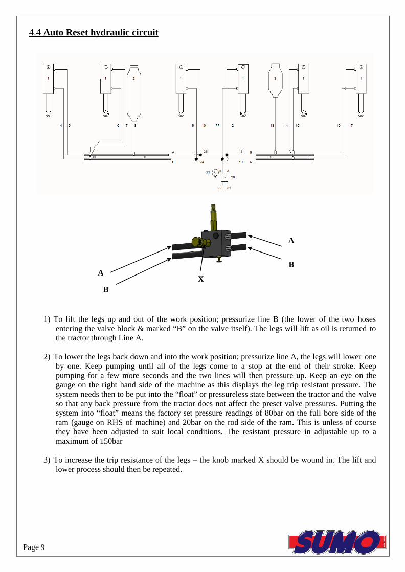
4.4 Auto Reset hydraulic circuit
A
B
1) To lift the legs up and out of the work position; pressurize line B (the lower of the two hoses entering the valve block & marked “B” on the valve itself). The legs will lift as oil is returned to the tractor through Line A.
2) To lower the legs back down and into the work position; pressurize line A, the legs will lower one
by one. Keep pumping until all of the legs come to a stop at the end of their stroke. Keep pumping for a few more seconds and the two lines will then pressure up. Keep an eye on the gauge on the right hand side of the machine as this displays the leg trip resistant pressure. The system needs then to be put into the “float” or pressureless state between the tractor and the valve so that any back pressure from the tractor does not affect the preset valve pressures. Putting the system into “float” means the factory set pressure readings of 80bar on the full bore side of the ram (gauge on RHS of machine) and 20bar on the rod side of the ram. This is unless of course they have been adjusted to suit local conditions. The resistant pressure in adjustable up to a maximum of 150bar
3) To increase the trip resistance of the legs – the knob marked X should be wound in. The lift and
lower process should then be repeated. Page 9

5.1 Maintenance
The packer bearings should be greased with one pump once a week and after washing off.
The disc bearings should be greased until old grease is forced out once a week when in normal use and after washing off.
The condition of the subsoiler legs, the points and the discs should be regularly monitored in order to maintain the most efficient use of the machine.
The condition and position of the packer scrapers should also be observed in order to prevent soil building up on the packer. Ensure the scrapers are not touching the packer though, as this will add rolling resistance as well as causing premature wear of the packer.
Hydraulic cylinders - Exposed chrome ram rods should also be lightly greased occasionally to prevent these valuable parts from rusting and causing costly oil leaks.
5.2 Spares
When ordering replacement parts please have your serial number, part numbers (listed in Section 6.0) and quantities at hand.
5.3 Winter storage
When machines are to be parked up for the winter period, correct storage techniques are an important part of protecting the machine to ensuring a hassle free season. When the machine has finished work it should be cleaned down and washed off to remove all traces of soil.
Following washing off, the packer bearings should be greased with one pump and the disc bearings should be greased until old grease is forced out. Other grease points are located on all rams on auto reset machines and these should receive two or three pumps of grease.
When the machine is parked up a note should be made of what wearing parts require replacing ready for the next seasons work. The wearing parts can then be ordered in time ready for the next season’s work in good time to avoid delays when the machine is required earlier than expected!
Page 10

6.1 Twin Disc Unit 6.0 Parts & Assembly
10 9 5 2
1
3 4
16
15
13 8
11 7
20 18
ITEM NO. PART NO. DESCRIPTION QTY.
12 17 6 14
1
SW391 (R/H. Not Shown) & SW390
(L/H)
Disc Arm
1
2 SW107 Clamp Plate 1 3 SWB103 Rubber 4 4 SWM1235CHSQ M12 x 35 Cup
Head Square 10
5 SWM12005 M12 Flanged Nut 10
6 SWB102 Bearing 1 7 SW101 Twin Disc Axle 1 8 SWB101 20" Scalloped
Disc 2
9 SWM3004 M30 Nylock Nut 1
10 SWM30001 M30 Washer 1
11
SW103 Dust Cover
and Convexed Disc
1
12
SW102
Dust Cover and
Concaved Disc
1
13 SW108 Disc Axle Washer 1
14 SWM16004 M16 Nylock Nut 2
DO NOT SCALE DRAWING
15 SWM16001 M16 Washer 2 MACHINE/COMPONENT: Sumo Trio 16 SWM16120 M16 x 120 Bolt 2
17 SW1153 M16 Washer (Thick) 2
TITLE:
Twin Disc Unit Assembly 18 SW646 Disc Scraper 1
19
SWB184 18" Scalloped Disc (end of disc row, Not
Shown)
1 Drawings and design information found
herein remain the sole property of Sumo UK Ltd. Reproductions may only be made with the permission of the owner.
20 SWM1240CHSQ M12 x 40 Cup Head Square 2
SCALE 1:20 REVISION: DATE: 15/10/12 INITIAL: TW

6.2 Single Disc Unit Assembly 5 2
4
1 15 3
8
9
14
6 10
12
7 13
ITEM NO. PART NO. DESCRIPTION QTY 16
17 11 18
1
SW390 (L/H) & SW391 (R/H, Not
Shown)
Disc Arm
1
2 SW107 Clamp Plate 1 3 SWB103 Rubber 4
4 SWM1235CHSQ M12 x 35 Cup Head Square 10
5 SWM12005 M12 Flanged Nut 10
6 SWB102 Bearing 1
7 SW109 Single Disc Axle 1
8 SWB101 20" Scalloped Disc 1
9 SWM30004 M30 Nylock Nut 1
10 SWM30001 M30 Washer 1
11
SW103 Dust Cover
and Convexed Disc
1
DO NOT SCALE DRAWING
12 SW108 Disc Axle Washer 1
MACHINE/COMPONENT: Sumo Trio 13 SWM16004 M16 Nylock
Nut 2 TITLE:
Single Disc Unit Assembly 14 SWM16001 M16 Washer 2 15 SWM16120 M16 x 120 Bolt 2 16 SW1153 M16 Washer
(Thick) 2 Drawings and design information found
herein remain the sole property of Sumo UK Ltd. Reproductions may only be made with the permission of the owner.
17 SW646 Disc Scraper 1
18 SWM1240CHSQ M12 x 40 Cup Head Square 2
SCALE 1:8 REVISION: DATE: 21/10/13 INITIAL: TW

6.3 Packer Bearing Assembly
14 4 1
3
2 8
6
10
7 13
5 9
12 6
11
ITEM NO. PART NO. DESCRIPTION QTY.
1 SW117 Trio Stand 1 2 SW118 Stand Pin 1 3 SWB105 Lynch Pin 1 4 SW1051 Front Packer Arm 1
5
SW1052R Offside
Rear Packer Arm 1
SW1052L Near Side 1
6 SWM2070 M20 x 70 Bolt 6 7 SWM20001 M20 Washer 14 DO NOT SCALE DRAWING 8 SWM20004 M20 Nylock Nut 7
MACHINE/COMPONENT:
Sumo Trio 9 SWM2060 M20 x 60 Bolt 1
TITLE:
Packer Bearing Assembly 10 SWB104 Packer Bearing 1 11 SWM1665 M 16 x 65 Bolt 4 12 SWM16001 M16 Washer 8 13 SWM16004 M16 Nylock Nut 4 Drawings and design information found
herein remain the sole property of Sumo UK Ltd. Reproductions may only be made with the permission of the owner.
14 SWB144 80mm Rubber Stand cap 1
SCALE 1:10 REVISION: DATE: 16/10/12 INITIAL: TW
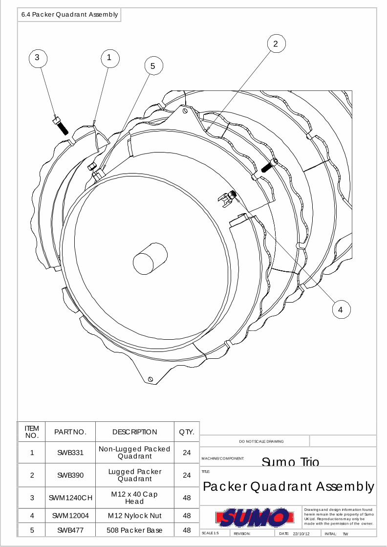
6.4 Packer Quadrant Assembly
2 3 1
5
4
ITEM NO. PART NO. DESCRIPTION QTY.
DO NOT SCALE DRAWING 1 SWB331 Non-Lugged Packed
Quadrant 24 MACHINE/COMPONENT: Sumo Trio
2
SWB390 Lugged Packer
Quadrant
24 TITLE:
Packer Quadrant Assembly 3 SWM1240CH M12 x 40 Cap
Head 48 Drawings and design information found
herein remain the sole property of Sumo UK Ltd. Reproductions may only be made with the permission of the owner.
4 SWM12004 M12 Nylock Nut 48
5 SWB477 508 Packer Base 48 SCALE 1:5 REVISION: DATE: 22/10/12 INITIAL: TW
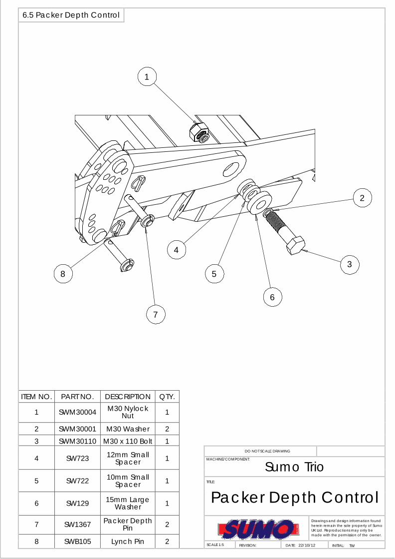
6.5 Packer Depth Control
1
2
4 3
8 5
6
7
ITEM NO. PART NO. DESCRIPTION QTY.
1 SWM30004 M30 Nylock Nut 1
2 SWM30001 M30 Washer 2 3 SWM30110 M30 x 110 Bolt 1
4
SW723 12mm Small
Spacer
1 DO NOT SCALE DRAWING
MACHINE/COMPONENT:
Sumo Trio 5 SW722 10mm Small
Spacer 1 TITLE:
Packer Depth Control 6 SW129 15mm Large Washer 1
7 SW1367 Packer Depth Pin 2 Drawings and design information found
herein remain the sole property of Sumo UK Ltd. Reproductions may only be made with the permission of the owner.
8 SWB105 Lynch Pin 2 SCALE 1:5 REVISION: DATE: 22/10/12 INITIAL: TW
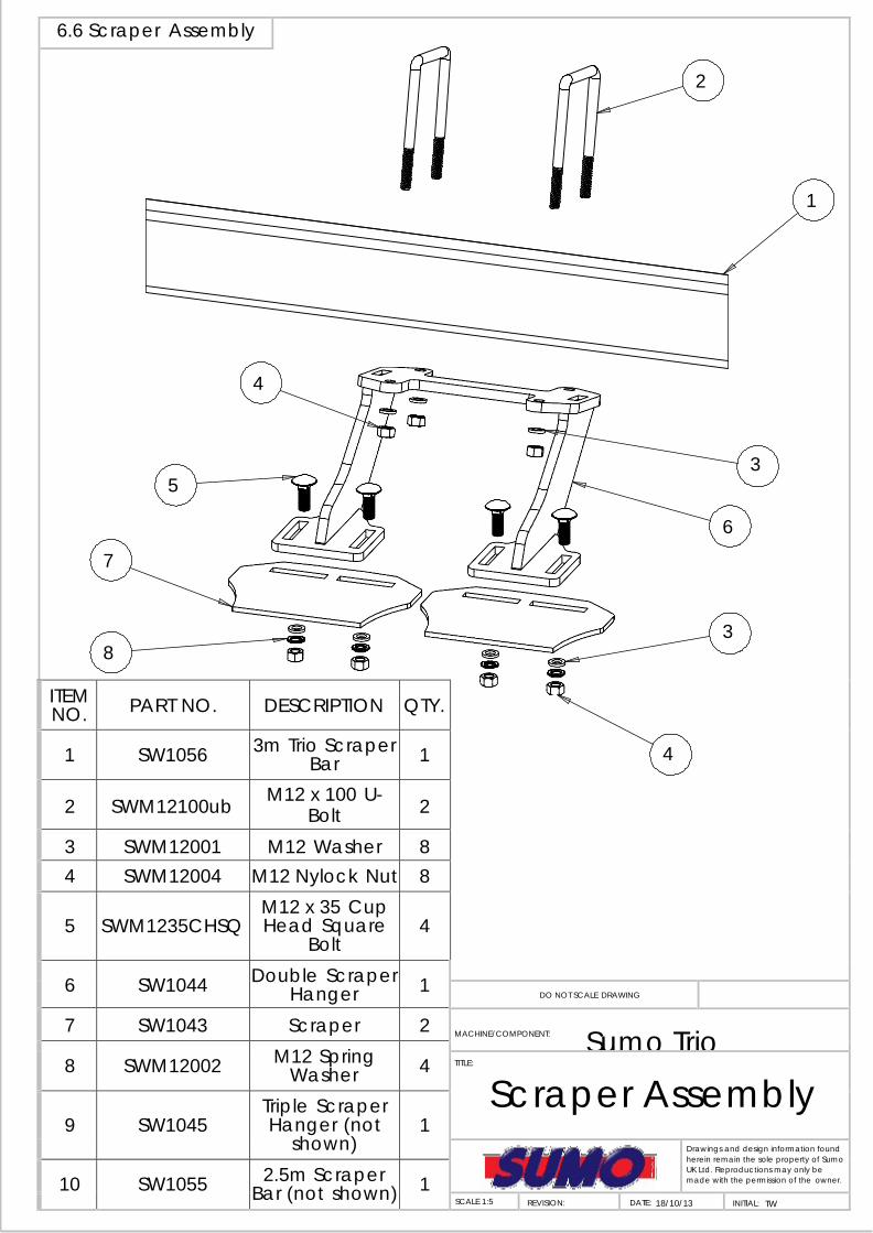
6.6 Scraper Assembly
2
1
4
3 5
6
7
3 8
ITEM NO. PART NO. DESCRIPTION QTY.
4 1 SW1056 3m Trio Scraper Bar 1
2 SWM12100ub M12 x 100 U-
Bolt 2
3 SWM12001 M12 Washer 8
4 SWM12004 M12 Nylock Nut 8
5 SWM1235CHSQ
M12 x 35 Cup Head Square
Bolt
4
6 SW1044 Double Scraper Hanger 1
DO NOT SCALE DRAWING
7 SW1043 Scraper 2 MACHINE/COMPONENT: Sumo Trio
8 SWM12002 M12 Spring Washer 4 TITLE:
Scraper Assembly 9
SW1045
Triple Scraper Hanger (not
shown)
1
Drawings and design information found herein remain the sole property of Sumo UK Ltd. Reproductions may only be made with the permission of the owner. 10 SW1055 2.5m Scraper
Bar (not shown) 1 SCALE 1:5 REVISION: DATE: 18/10/13 INITIAL: TW

6.7 End Scraper Assembly
1
3
4 2
5
10
9
ITEM NO. PART NO. DESCRIPTION QTY.
6
7
8
1 SW1056 3m Scraper Bar 1
2 SWM2070 M20 x 70 Bolt 2
3 SWM20001 M20 Washer 4
4 SWM20004 M20 Nylock Nut 2
5 SWM1235CHSQ
M12 x 35 Cup Head Square
Bolt
2
6 SWM12001 M12 Washer 2
7 SWN12002 M12 Spring Washer 2
8 SWM12004 M12 Nylock Nut 2
DO NOT SCALE DRAWING
9 SW1053 End Scraper 1 MACHINE/COMPONENT: Sumo Trio
10 SW1059 End Scraper Hanger (R/H) 1 TITLE:
End Scraper Assembly 11
SW1058
End Scraper Hanger (L/H)not
shown
1
Drawings and design information found herein remain the sole property of Sumo UK Ltd. Reproductions may only be made with the permission of the owner. 12 SW1055 2.5m Scraper
Bar (not shown) 1 SCALE 1:3 REVISION: DATE: 18/10/13 INITIAL: TW

6.8 Auto Reset Assembly
4
5 6
2
14 3
15 8 12
13
7 1
ITEM NO. PART NO. DESCRIPTION QTY.
9 10
11
1 SW1017 Cast Socket 1 2 SWH328 705/1 Ram 1
3 SWB374 Spring Tension Bush 30x36x25 2
4 SWM30200 M30 x 200 Bolt 1 5 SWM30001 M30 Washer 1 6 SWM30004 M30 Nylock Nut 1
7 SW183 30mm x 180mm Tabbed Pin 1
8 SW188 30x40x45mm PB1 Bush 2
9
SW1192 & SW1192R
30mm x 120mm Tabbed Pin c/w Grease Nipple
(L/H & R/H)
1
DO NOT SCALE DRAWING
MACHINE/COMPONENT: Sumo Trio
10 SWM1240 M12 x 40 Bolt 1 TITLE:
Auto Reset Assembly 11 SWM12130 M12 x 130 bolt 1 12 SWM12001 M12 Washer 2 13 SWM12004 M12 Nylock Nut 2
Drawings and design information found herein remain the sole property of Sumo UK Ltd. Reproductions may only be made with the permission of the owner.
14 SWB105 Lynch Pin 1 15 SW451 Leg Depth Pin 1
Scale 1:5 REVISION: DATE: 19/1012 INITIAL: TW

6.9 Shear Bar Assembly 7
2 5
6
4 10
3
11 10 18
8 9 17
10 12 13
15 14
16
ITEM NO. PART NO. DESCRIPTION QTY. 1
1 SW1017 Cast Socket 1
2 SW1196 Shear Bar Socket 1
3 SW1197 Shear Push Rod 1 4 SWM30200 M30 x 200 Bolt 2 5 SWM30004 M30 Nylock Nut 2
6 SW1198 50 x 30 x 15mm Spacer 2
7 SWB106 Shear Bar R-Clip 1 8 SWB160 Shear Bar 1 9 SWM1270 M12 x 70 bolt 1
10 SWM12004 M12 Nylock Nut 3 11 SWM120001 M30 Washer 2
12 SW188 30 x 40 x 45mm PB1 Bush 2
DO NOT SCALE DRAWING
13 SWM1240 M12 x 40 Bolt 1 MACHINE/COMPONENT: Sumo Trio
14 SWM12130 M12 x 130 Bolt 1
15 SW183 30 x 170mm Tabbed Pin 1
TITLE:
Shear Bar Assembly 16 SW1192 &
SW1192R 30 x 120mm Pivot Pin c/w Grease
Nipple (L/H & R/H)
1
Drawings and design information found herein remain the sole property of Sumo UK Ltd. Reproductions may only be made with the permission of the owner. 17 SW451 Leg Depth Pin 1
18 SWB105 Lynch Pin 1 SCALE 1:7 REVISION: DATE: 29/11/12 INITIAL: TW

6.10 Trio Leg Assembly
1
10
2
3
9 5
7 6
8
DO NOT TIGHTEN POINTS UP WITH AIR RACHETS OR OVER TIGHTEN WITH SPANNERS.
EXCESSIVE TIGHTENING WILL RESULT IN POINTS CRACKING ITEM NO. PART NO. DESCRIPTION QTY.
4
11
1 SW1046 Trio Leg 1
2 SW1048 Cast Shin 1
3 SWB183 M10 x 30 Roll Pin 1
4 SW1050 Concord Point 1
5 SWM1250 M12 x 50 Bolt 1 6 SWM12004 M12 Nylock Nut 1
7
SWB401/400 4" R/H Wing & L/H
Wing (Not Shown)
2
8
SWB366/367 8" L/H Wing & R/H
Wing (Not Shown)
2 DO NOT SCALE DRAWING
9
SWM1235TN
M12 x 35 Twin Nibbed Bolt c/w
Plain Nut
4
MACHINE/COMPONENT: Sumo Trio
TITLE:
Trio Leg Assembly
10
SW1047 Trio Weld on Leg Bottom
1
11
SWB441
Low Disturbance
Point
1
Drawings and design information found herein remain the sole property of Sumo UK Ltd. Reproductions may only be made with the permission of the owner.
SCALE 1:6 REVISION: DATE: 19/10/12 INITIAL: TW

6.11 Alternate Leg Assembly
8 1
4
7 7
2
3 5
6
DO NOT TIGHTEN POINTS UP WITH AIR RACHETS OR OVER TIGHTEN WITH SPANNERS.
EXCESSIVE TIGHTENING WILL RESULT IN POINTS CRACKING
ITEM NO. PART NO. DESCRIPTION QTY. 1 SW777 Combi Trio Leg 1 2 SWM1660 M16 x 60 Bolt 1 3 SWM16004 M16 Nylock Nut 1
DO NOT SCALE DRAWING 4 SW1100 Combi Trio Point 1 MACHINE/COMPONENT: Sumo Trio 5 SW165/164 4" L/H Wing & R/H
Wing (Not Shown) 2 TITLE:
Alternate Trio Leg Assembly 6 SW157/158 8" R/H Wing & L/H
Wing (Not Shown) 2
7
SWM1235TN
M12 x 35 Twin Nibbed Bolt c/w
Plain Nut
4
Drawings and design information found herein remain the sole property of Sumo UK Ltd. Reproductions may only be made with the permission of the owner. 8 SW354 Trio Leg Weld on
Bottom 1 SCALE 1:6 REVISION: DATE: 19/10/12 INITIAL: TW

6.12 Soil Retainer Assembly
3
8 5
2 4
7
6 1
ITEM NO. PART NO. DESCRIPTION QTY.
1 SW1061 R/H Soil Retainer 1 2 SWM2080 M20 x 80 Bolt 4 3 SWM20001 M20 Flat Washer 6
DO NOT SCALE DRAWING 4 SW125 12mm Small
Spacer 4 MACHINE/COMPONENT: Sumo Trio
5 SW126 10mm Small Spacer 4
TITLE:
Soil Retainer Assembly 6 SW123 12mm Large
Spacer 4
7 SW1049 Soil Retainer Hanger 2
Drawings and design information found herein remain the sole property of Sumo UK Ltd. Reproductions may only be made with the permission of the owner.
8 SWM20004 M20 Nylock Nut 4
9 SW1062 L/H Soil Retainer (not shown) 1
SCALE 1:8 REVISION: DATE: 22/10/12 INITIAL: TW

6.13 Light Assembly
7
3
6 8
10
11 4
5
9 1
ITEM NO. PART NO. DESCRIPTION QTY.
1 SW1193 L/H Light Bracket 1
2
SW1194 R/H Light Bracket
(not shown)
1
3 SWB174 Rear Light with Block Connector 1
4 SWB162 Warning Triangle 1
5 SWM616CSK M6 x 16 Countersunk Bolt 2
DO NOT SCALE DRAWING
6 SWM6001 M6 Washer 4 MACHINE/COMPONENT: Sumo Trio 7 SWM6003 M6 Plain Nut 2
8 SWM6004 M6 Nylock Nut 2 TITLE:
Light Assembly 9 SWM1045 M10 x 45 Bolt 2
10 SWM10001 M10 Washer 2 11 SWM10004 M10 Nylock Nut 2
12
SWB175
Mounted Trio Wiring Loom (not
shown)
1
Drawings and design information found herein remain the sole property of Sumo UK Ltd. Reproductions may only be made with the permission of the owner.
SCALE 1:5 REVISION: DATE: 22/11/12 INITIAL: TW

6.14 Main Frame
1 9
6 3
7
4 4
8 5
2 ITTEM NO. PART NO. DESCRIPTION QTY.
1
SW1068 3m Auto reset &
Shear Pin Trio Frame
1
2 SW626 Cat III Lower Link Pin 2
3 SW627 Cat III Top Link Pin 1
4 SWB107 Lynch Pin 3
5 SW1141 Lower Link Pin Spacer 2
DO NOT SCALE DRAWING MACHINE/COMPONENT: Sumo Trio
6 SW1142 Top Link Pin Spacer 1 TITLE:
Main Frame 7 SW1195 Trio Front Stand 2 8 SW118 Font Stand Pin 2 9 SWB107 Large Lynch Pin 2
Drawings and design information found herein remain the sole property of Sumo UK Ltd. Reproductions may only be made with the permission of the owner.
10
SW1067
2.5m Auto reset & Shear Bar Trio Frame
(not shown)
1
SCALE 1:17 REVISION: DATE: 23/11/12 INITIAL: TW

6.15 Disc Frame
1
3 2
4
ITEM NO. PART NO. DESCRIPTION QTY.
DO NOT SCALE DRAWING
MACHINE/COMPONENT: Sumo Trio 1 SW1307 3m Trio Disc Frame 1
TITLE:
Disc Frame
2 SWM2060 M20 x 60 Bolt 4 3 SWM20004 M20 Nylock Nut 4
4 SWM20001 M20 Washer 8 Drawings and design information found herein remain the sole property of Sumo UK Ltd. Reproductions may only be made with the permission of the owner. 5 SW1428 2.5m Trio Disc
Frame 1 SCALE 1:15 REVISION: DATE: 21/10/13 INITIAL: TW
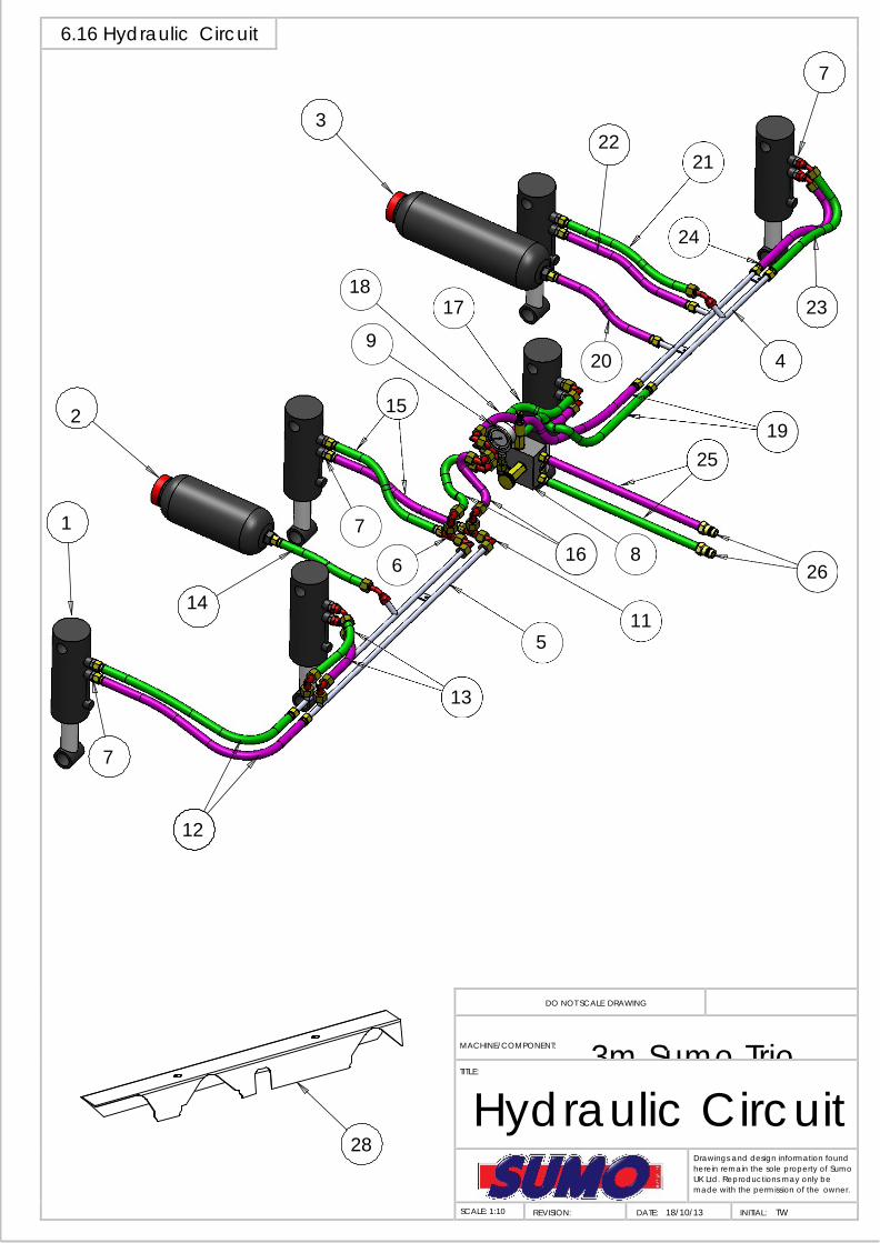
6.16 Hydraulic Circuit
7
3 22
21
24
18 17 23
9 20 4
2 15 19
25
1 7
6 16 8 26
14 11
5
13
7
12
28
DO NOT SCALE DRAWING
MACHINE/COMPONENT: 3m Sumo Trio TITLE:
Hydraulic Circuit
Drawings and design information found herein remain the sole property of Sumo UK Ltd. Reproductions may only be made with the permission of the owner.
SCALE: 1:10 REVISION: DATE: 18/10/13 INITIAL: TW

6.16 Hydraulic Circuit Cont.
ITEM NO. PART NO. DESCRIPTION QTY.
1 SWH328 705/1 Ram 6 2 SWH330 3L Accumulator 1 3 SWH331 1.5L Accumulator 1 4 SWH332 Fixed Pipe Assembly (LH) 1
5 SWH333 Fixed Pipe Assembly (RH) 1
6 SWH156 12L T 2 7 SWH303 12L - 3/8 Adaptor 12
8 SWH298 Auto Reset Valve 1 9 SWH181 Pressure Gauge 1
10 SWH155 12L Cross 2 11 SWH265 12L 90 2 12 SWH334 3/8 hose 12LSF/ 12LSF 640mm 2 13 SWH335 3/8 hose 12L45/ 12L90C 210mm 2 14 SWH336 3/8 hose 12L45/ 15LSF 280mm 1 15 SWH338 3/8 hose 12LSF/ 12LSF 350mm 2 16 SWH350 3/8 hose 12L90C/ 12L90SW 450mm 2 17 SWH341 3/8 hose 12L90C/ 12L90SW 340mm 1 18 SWH342 3/8 hose 12L90C/ 12L90SW 380mm 1 19 SWH337 3/8 hose 12LSF/ 12LSF 610mm 2 20 SWH343 3/8 hose 12LSF/ 15LSF 390mm 1 21 SWH344 3/8 hose 12LSF/ 12L45 370mm 1 22 SWH345 3/8 hose 12LSF/ 12LSF 335mm 1 23 SWH346 3/8 hose 12LSF/ 12L45 310mm 1 24 SWH347 3/8 hose 12LSF/ 12L45 300mm 1 25 SWH349 3/8 hose 12LSF/ 1/2M 1500mm 2 26 SWH147 Quick Release Coupling 2
27 SW1161 Fixed Pipe Cover (L/H) not shown 1
28 SW1162 Fixed Pipe Cover (R/H) 1
DO NOT SCALE DRAWING
MACHINE/COMPONENT: 3m Sumo Trio
TITLE:
Hydraulic Circuit
Drawings and design information found herein remain the sole property of Sumo UK Ltd. Reproductions may only be made with the permission of the owner.
SCALE 1:10
REVISION:
DATE:
18/10/13
INITIAL: TW

6.17 Hydraulic Circuit
1
3 10
22
11 23
20 21
16 19 4 17
9 2 10 7
18
13 24
14 8 6
15 14
12 25
5
1
11
DO NOT SCALE DRAWING
MACHINE/COMPONENT: 2.5m Sumo Trio
TITLE:
27
Hydraulic Circuit Drawings and design information found herein remain the sole property of Sumo UK Ltd. Reproductions may only be made with the permission of the owner.
SCALE 1:12
REVISION:
DATE: 22/11/12
INITIAL: TW
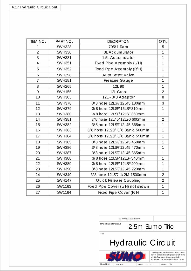
6.17 Hydraulic Circuit Cont.
ITEM NO. PART NO. DECRIPTION QTY. 1 SWH328 705/1 Ram 5 2 SWH330 3L Accumulator 1 3 SWH331 1.5L Accumulator 1 4 SWH351 Fixed Pipe Assembly (L/H) 1 5 SWH352 Fixed Pipe Assembly (R/H) 1 6 SWH298 Auto Reset Valve 1 7 SWH181 Pressure Gauge 1 8 SWH265 12L 90 1 9 SWH155 12L Cross 2
10 SWH303 12L - 3/8 Adaptor 8 11 SWH378 3/8 hose 12LSF/12L45 180mm 3 12 SWH379 3/8 hose 12LSF/15LSF 310mm 1 13 SWH380 3/8 hose 12LSF/12LSF 360mm 1 14 SWH381 3/8 hose 12L45/12L90 600mm 2 15 SWH382 3/8 hose 12LSF/12L45 365mm 1 16 SWH383 3/8 hose 12L90/ 3/8 Banjo 500mm 1 17 SWH384 3/8 hose 12L90/ 3/8 Banjo 550mm 1 18 SWH385 3/8 hose 12LSF/12L45 450mm 1 19 SWH386 3/8 hose 12LSF/12L45 470mm 1 20 SWH387 3/8 hose 12LSF/12L45 365mm 1 21 SWH388 3/8 hose 12LSF/12LSF 340mm 1 22 SWH389 3/8 hose 12LSF/12LSF 400mm 1 23 SWH390 3/8 hose 12LSF/12L45 220mm 1 24 SWH349 3/8 hose 12LSF/ 1/2M 1500mm 2 25 SWH147 Quick Release Coupling 2 26 SW1163 Fixed Pipe Cover (L/H) not shown 1 27 SW1164 Fixed Pipe Cover (R/H 1
DO NOT SCALE DRAWING
MACHINE/COMPONENT: 2.5m Sumo Trio
TITLE:
Hydraulic Circuit
Drawings and design information found herein remain the sole property of Sumo UK Ltd. Reproductions may only be made with the permission of the owner.
SCALE 1:12
REVISION:
DATE:
22/11/12
INITIAL: TW

6.18 Stickers and Paint
Sticker Description Quantity Part No.
Big Sumo horizontal sticker 450 x 125mm
2
SWB125
Big Trio 3 sticker 320 x 125mm
2
SU006
Big Union Jack sticker 150 x 100mm
2
SWB127
Vertical Sumo sticker 80 x 295mm
2
SWB128
Small Union Jack sticker
2
SWB129
Small Sumo Horizontal Sticker
6
SWB130
Sumo touch up paint Sumo Red 1/2 Litre
SWB131 Sumo Black 1/2 Litre SWB132