2015 OPEN ACCESS applied sciences - pdfs.semanticscholar.org · Appl. Sci. 2015, 5 771 type of...
17
Appl. Sci. 2015, 5, 770-786; doi:10.3390/app5040770 applied sciences ISSN 2076-3417 www.mdpi.com/journal/applsci Article Design of the Secondary Optical Elements for Concentrated Photovoltaic Units with Fresnel Lenses Yi-Cheng Chen * and Hung-Wei Chiang Department of Mechanical Engineering, National Central University, Taoyuan 320, Taiwan; E-Mail: [email protected] * Author to whom correspondence should be addressed; E-Mail: [email protected]; Tel.: +886-3-4267313. Academic Editor: Wen-Hsiang Hsieh Received: 31 July 2015 / Accepted: 30 September 2015 / Published: 12 October 2015 Abstract: The goal of this presented study was to determine the optimum parameters of secondary optical elements (SOEs) for concentrated photovoltaic (CPV) units with flat Fresnel lenses. Three types of SOEs are under consideration in the design process, including kaleidoscope with equal optical path design (KOD), kaleidoscope with flat top surface (KFTS), and open-truncated tetrahedral pyramid with specular walls (SP). The function of using a SOE with a Fresnel lens in a CPV unit is to achieve high optical efficiency, low sensitivity to the sun tracking error, and improved uniformity of irradiance distribution on the solar cell. Ray tracing technique was developed to simulate the optical characteristics of the CPV unit with various design parameters of each type of SOE. Finally, an optimum KOD-type SOE was determined by parametric design process. The resulting optical performance of the CPV unit with the optimum SOE was evaluated in both single-wavelength and broadband simulation of solar spectrum. Keywords: concentrated photovoltaic; secondary optical element; Fresnel Lens; optical efficiency 1. Introduction A concentrated photovoltaic (CPV) unit is generally composed of a primary optical element (POE), a secondary optical element (SOE) and a solar cell. The function of the POE is to concentrate a large-area solar energy into a small III-V solar cell. Furthermore, the SOE is applied to redirect the sun light into the solar cell and to distribute the energy uniformly on the solar cell [1–3]. The most common OPEN ACCESS
Transcript of 2015 OPEN ACCESS applied sciences - pdfs.semanticscholar.org · Appl. Sci. 2015, 5 771 type of...

Appl. Sci. 2015, 5, 770-786; doi:10.3390/app5040770
applied sciences ISSN 2076-3417
www.mdpi.com/journal/applsci
Article
Design of the Secondary Optical Elements for Concentrated Photovoltaic Units with Fresnel Lenses
Yi-Cheng Chen * and Hung-Wei Chiang
Department of Mechanical Engineering, National Central University, Taoyuan 320, Taiwan;
E-Mail: [email protected]
* Author to whom correspondence should be addressed; E-Mail: [email protected];
Tel.: +886-3-4267313.
Academic Editor: Wen-Hsiang Hsieh
Received: 31 July 2015 / Accepted: 30 September 2015 / Published: 12 October 2015
Abstract: The goal of this presented study was to determine the optimum parameters of
secondary optical elements (SOEs) for concentrated photovoltaic (CPV) units with flat
Fresnel lenses. Three types of SOEs are under consideration in the design process, including
kaleidoscope with equal optical path design (KOD), kaleidoscope with flat top surface
(KFTS), and open-truncated tetrahedral pyramid with specular walls (SP). The function of
using a SOE with a Fresnel lens in a CPV unit is to achieve high optical efficiency, low
sensitivity to the sun tracking error, and improved uniformity of irradiance distribution on the
solar cell. Ray tracing technique was developed to simulate the optical characteristics of the
CPV unit with various design parameters of each type of SOE. Finally, an optimum KOD-type
SOE was determined by parametric design process. The resulting optical performance of the
CPV unit with the optimum SOE was evaluated in both single-wavelength and broadband
simulation of solar spectrum.
Keywords: concentrated photovoltaic; secondary optical element; Fresnel Lens; optical efficiency
1. Introduction
A concentrated photovoltaic (CPV) unit is generally composed of a primary optical element
(POE), a secondary optical element (SOE) and a solar cell. The function of the POE is to concentrate
a large-area solar energy into a small III-V solar cell. Furthermore, the SOE is applied to redirect the sun
light into the solar cell and to distribute the energy uniformly on the solar cell [1–3]. The most common
OPEN ACCESS

Appl. Sci. 2015, 5 771
type of refractive POE is a flat Fresnel lens. In addition, there are two major materials for Fresnel lens,
i.e., PMMA and Silicone-on-Glass, and the latter is believed to have a better outdoor life and reliability
under solar radiation and humidity [4–7].
If only a POE is applied in a photovoltaic system, nonuniformity of the concentrated distribution on
the solar cell surface is observed, resulting in localized hot spot or even damage of the solar cell [1,8].
Localized hot spots and poor uniformity will reduce efficiency of the photovoltaic system and service
life of the solar cell. Keeping the power production of a photovoltaic system in real operation conditions
under influences of wind and vibration is important. Therefore, precise orientation to the sun of the
photovoltaic system is required. One of the ways for lowering the effect of the inaccurate orientation on
the concentrator system power efficiency and for improving the irradiation uniformity on the solar cell
surface is the application of the SOE located before the solar cell [8,9].
Secondary optical elements are specular or refracting optical elements of various forms. The
parameters of SOE used in a CPV unit are usually tailored according to the design parameters of the
POE, performance requirements and the size of the solar cell [8]. Using a SOE with a Fresnel lens in a
CPV unit will achieve high optical efficiency, lower the sensitivity to the sun tracking error, and improve
the uniformity of irradiance distribution on a solar cell [8–10].
The three major factors used in evaluating a CPV system include the optical efficiency, the acceptance
angle and the uniformity of irradiance distribution on the solar cell. The optical efficiency of a photovoltaic
system is defined as the ratio of the radiant flux on the solar cell and the POE surface. The acceptance
angle θ90% is commonly defined as the incidence angle corresponding to 90% of the maximum optical
efficiency at normal incidence.
In other words, the optical characteristic of a CPV unit is highly affected by the design of the SOE.
Therefore, an optimum SOE tailored for a specific CPV unit is essential to achieve the highest optical
performance. Andree et al. proposed optimization of SOE for CPV unit with a flat Fresnel lens [8].
Recently, Zhuang and Yu applied simplex algorithm to attain optimum prism displacements of a Fresnel
lens, leading to a uniformity irradiance on the solar cell with broad solar spectrum [11]. Buljan et al.
achieved high uniformity and chromatic balance for CPV system by using a dielectric solid RXI-type
SOE in a CPV system comprising a flat Fresnel lens [12]. Lv et al. analyzed the performance of a CPV
module considering the temperature-dependent model of the optical elements and the solar cell. [13].
In this study, the size of the square Fresnel lens is 40 mm × 40 mm, the size the solar cell is
1.25 mm × 1.25 mm, and the theoretical geometric concentration ratio is 1024. The square solar cell is
placed on the focal plane of the POE, of which the focal length is 130.1 mm. The Fresnel lens is made
by silicone-on-glass with urethane prism grooves of pitch 0.2 mm on a 2 mm thick flat BK7 glass, and
the internal transmittance of BK7 is assumed as 0.99 in the simulation [12]. The commercial package,
ASAP (Breault Research Organization, Inc., Tucson, AZ, USA), was applied to perform the optical
simulations in this research.
In addition, light source with a divergence angle of 0.265 degrees and AM1.5D were assumed in the
simulation. The Fresnel loss occurring at all interfaces/surfaces was also considered in the ray-tracing
process. In the preliminary design steps of SOE, a single wavelength of 550 nm of solar spectrum was
considered to determine the basic optical characteristic of the CPV unit with various SOE designs. The
indexes of refraction of BK7 and urethane at 550 nm are 1.518 and 1.510, respectively [14]. Finally, the

Appl. Sci. 2015, 5 772
optical characteristics of the CPV unit with the optimum SOE were evaluated in broadband solar
spectrum in the range of 400–1300 nm.
2. Preliminary Design of SOEs
Table 1 summarizes the major optical properties and design parameters of the silicone-on-glass
Fresnel lens used in the CPV unit. Three types of SOEs were evaluated in the preliminary design process,
including (1) kaleidoscope with equal optical path design (KOD); (2) kaleidoscope with flat top surface
(KFTS); and (3) open-truncated tetrahedral pyramid with specular walls (SP). The former two are
refractive type made by BK7 and the last one is reflective type [8,9].
Table 1. Design parameters of the concentrated photovoltaic (CPV) unit with a flat Fresnel lens.
Size of Fresnel Lens 40 mm × 40 mm
Thickness of Fresnel lens 2 mm Material Silicone-on-Glass (BK7)
Light source divergence angle of 0.265 degrees Radian flux 1.36 W Wavelength 550 nm
Index of Refraction of BK7 1.518 Index of Refraction of Urethane 1.510
Size of solar cell 1.25 mm × 1.25 mm Geometrical concentration ratio 1024
Focal length 130.1 mm Prism pitch of Fresnel lens 0.2 mm
2.1. KOD-Type SOE
The design concept of KOD-type SOE comprises law of refraction, law of reflection, marginal ray,
equal-optical path design and imaging optics [1,2,8,9,15]. Figure 1 illustrates the KOD-type SOE,
comprising an ellipsoidal-top and a middle cone part. Total internal reflection (TIR) occurs at the internal
surface of the bottom section, which is placed in front of the solar cell. The initial designed incidence
angle Ii of the KOD-type SOE was 1.2°.
(a) (b)
Figure 1. Illustration of KOD-type SOE (a) design parameters; (b) solid model.

Appl. Sci. 2015, 5 773
Figure 2 shows the optical efficiency of the flat Fresnel lens with the KOD-type SOE and the effect
of incidence angle on the optical efficiency. According to the simulation results shown in Figure 2, the
optical performance can be determined as follows: the optical efficiency under normal incidence is 84.6%,
the acceptance angle is 1.2° with an optical efficiency of 76.2%. Moreover, the optical efficiency drops
to only 5% at an incidence angle of 2°. When the incidence angle is smaller than 1.2°, most of the incident
rays refracted from the POE will be refracted at the top elliptical surface of the KOD-type SOE and then
be reflected (due to TIR) at the bottom surface to the solar cell. Figure 3a demonstrates the ray-tracing
results when the incidence angle is 0.4°, where only a few rays will not enter the solar cell. On the other
hand, when the incidence deviation is larger than 1.2°, more light rays will not have second reflection
after TIR at the bottom section of the SOE, and those rays will not enter the solar cell, as shown in
Figure 3b. Consequently, the optical efficiency drops largely after the incidence angle is larger than 1.2°.
Figure 2. Optical efficiency of the Fresnel lens with KOD-type SOE.
(a) (b)
Figure 3. Ray tracing inside the KOD-type SOE (a) incidence angle = 0.4°; (b) incidence
angle of 1.2°.
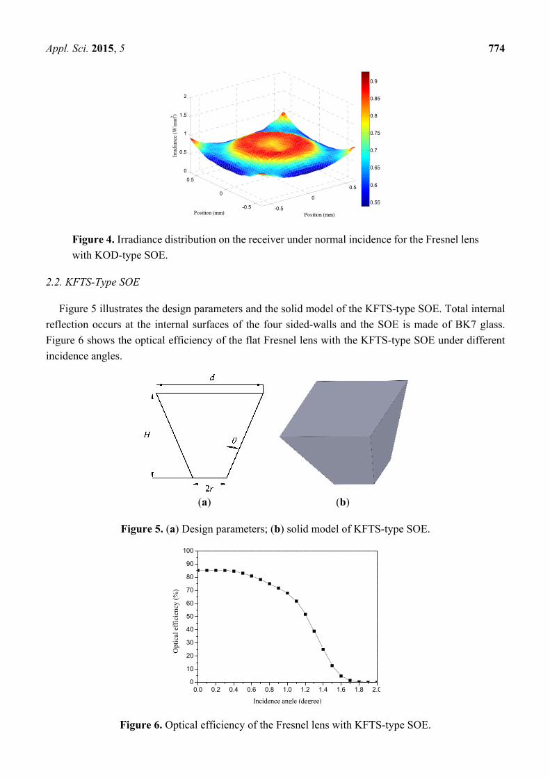
Figure 4 shows the irradiance distribution on the solar cell under normal incidence. The irradiance
distribution is uniform by using the KOD-type SOE, and the peak value of irradiance shown in Figure 4
is 0.9291 W/mm2 over an average irradiance of 0.7372 W/mm2.
0.0 0.2 0.4 0.6 0.8 1.0 1.2 1.4 1.6 1.8 2.00
10
20
30
40
50
60
70
80
90
100
Opt
ical
eff
icie
ncy
(%)
Incidence angle (degree)
Appl. Sci. 2015, 5 774
Figure 4. Irradiance distribution on the receiver under normal incidence for the Fresnel lens
with KOD-type SOE.
2.2. KFTS-Type SOE
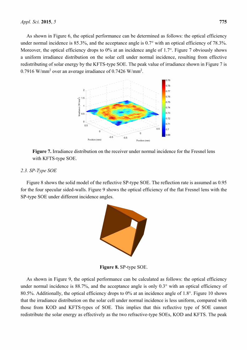
Figure 5 illustrates the design parameters and the solid model of the KFTS-type SOE. Total internal
reflection occurs at the internal surfaces of the four sided-walls and the SOE is made of BK7 glass.
Figure 6 shows the optical efficiency of the flat Fresnel lens with the KFTS-type SOE under different
incidence angles.
(a) (b)
Figure 5. (a) Design parameters; (b) solid model of KFTS-type SOE.
Figure 6. Optical efficiency of the Fresnel lens with KFTS-type SOE.
-0.5
0
0.5
-0.5
0
0.5
0
0.5
1
1.5
2
Position (mm)Position (mm)
Irra
dian
ce (
W/m
m2 )
0.55
0.6
0.65
0.7
0.75
0.8
0.85
0.9
0.0 0.2 0.4 0.6 0.8 1.0 1.2 1.4 1.6 1.8 2.00
10
20
30
40
50
60
70
80
90
100
Opt
ical
eff
icie
ncy
(%)
Incidence angle (degree)
Appl. Sci. 2015, 5 775
As shown in Figure 6, the optical performance can be determined as follows: the optical efficiency
under normal incidence is 85.3%, and the acceptance angle is 0.7° with an optical efficiency of 78.3%.
Moreover, the optical efficiency drops to 0% at an incidence angle of 1.7°. Figure 7 obviously shows
a uniform irradiance distribution on the solar cell under normal incidence, resulting from effective
redistributing of solar energy by the KFTS-type SOE. The peak value of irradiance shown in Figure 7 is
0.7916 W/mm2 over an average irradiance of 0.7426 W/mm2.
Figure 7. Irradiance distribution on the receiver under normal incidence for the Fresnel lens
with KFTS-type SOE.
2.3. SP-Type SOE
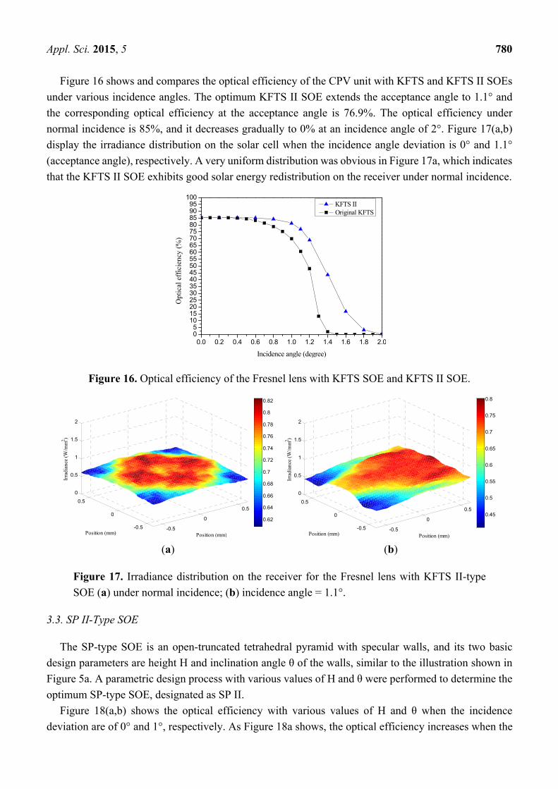
Figure 8 shows the solid model of the reflective SP-type SOE. The reflection rate is assumed as 0.95
for the four specular sided-walls. Figure 9 shows the optical efficiency of the flat Fresnel lens with the
SP-type SOE under different incidence angles.
Figure 8. SP-type SOE.
As shown in Figure 9, the optical performance can be calculated as follows: the optical efficiency
under normal incidence is 88.7%, and the acceptance angle is only 0.3° with an optical efficiency of
80.5%. Additionally, the optical efficiency drops to 0% at an incidence angle of 1.8°. Figure 10 shows
that the irradiance distribution on the solar cell under normal incidence is less uniform, compared with
those from KOD and KFTS-types of SOE. This implies that this reflective type of SOE cannot
redistribute the solar energy as effectively as the two refractive-type SOEs, KOD and KFTS. The peak
-0.5
0
0.5
-0.5
0
0.5
0
0.5
1
1.5
2
Position (mm)Position (mm)
Irra
dian
ce (
W/m
m2 )
0.69
0.7
0.71
0.72
0.73
0.74
0.75
0.76
0.77
0.78
0.79

Appl. Sci. 2015, 5 776
value of irradiance shown in Figure 10 is 1.0555 W/mm2 over an average irradiance of
0.7734 W/mm2.
Figure 9. Optical efficiency of the Fresnel lens with SP-type SOE.
Figure 10. Irradiance distribution on the receiver under normal incidence for the Fresnel
lens with SP-type SOE.
2.4. Comparison of Three Types of SOE
Table 2 summarizes the optical performances of the three types of SOE based on the simulated results
presented in the preceding sections. The focal distance of the POE is the same for the three-types of
SOE. The optical performance of the CPV unit without any SOE is also listed in Table 2 for comparison
purpose. According to Table 2, the following can be observed: (1) the CPV unit with the KOD-type SOE
exhibits a highest acceptance angle of 1.2° among the three preliminary types of SOE, while the SP-type
SOE has a relatively limited improvement on the acceptance angle (only 0.3°); (2) The CPV unit with
the SP-type SOE yields a highest optical efficiency at normal incidence (88.7%), while the KOD- and
KFTS-types of SOE lead to similar optical efficiency under normal incidence (84.6% and 85.3%,
respectively); (3) The irradiance distribution on the solar cell is most uniform with the KFTS-type SOE,
and the SP-type of SOE has insignificant improvement on the irradiance uniformity on the solar cell;
(4) The SP-type SOE is believed to have the easiest manufacturing processes and the lowest cost among
the three-types of SOEs.
0.0 0.2 0.4 0.6 0.8 1.0 1.2 1.4 1.6 1.8 2.00
10
20
30
40
50
60
70
80
90
100
Opt
ical
eff
icie
ncy
(%)
Incidence angle (degree)
-0.5
0
0.5
-0.5
0
0.50
0.5
1
1.5
2
Position (mm)Position (mm)
Irra
dian
ce (
W/m
m2 )
0.1
0.2
0.3
0.4
0.5
0.6
0.7
0.8
0.9
1

Appl. Sci. 2015, 5 777
Table 2. Comparison of the optical performance of the Fresnel lens with three types of
secondary optical elements (SOE).
SOE No SOE KOD KFTS SP
Acceptance angle (degree) 0.1 1.2 0.7 0.3 Optical efficiency under normal incidence (%) 85 84.6 85.3 88.7 Optical efficiency at the acceptance angle (%) 75.8 76.2 78.3 80.5
Peak value of irradiance on the receiver under normal incidence (W/mm2) 1.0557 0.9291 0.7916 1.0555
In addition, Figure 11 shows the optical efficiency of the three types of SOE under different incidence
angles. It can be observed that the KOD-type is most insensitive to the deviation of incidence angle. The
three types of SOE were explored for further optimization design in the following section.
Figure 11. Optical efficiency of the Fresnel lens with three types of SOE.
3. Optimum Design of SOE
3.1. KOD II-Type SOE
To achieve the optimum parameters of the KOD-type SOE, the following steps of optimization design
process were performed:
(1) The original prism pitch of the Fresnel lens with the KOD-type SOE was 0.2 mm. The resulting
optical efficiencies under various prism pitch, ranging from 0.2 mm to 1.4 mm, were calculated
and compared, as shown in Figure 12a. Figure 12a shows that when the prism pitch was 1.0 mm,
the optical efficiencies under normal incidence and at an incidence deviation of 1.2° were both
the highest. Hence, the prism pitch was selected as 1 mm.
(2) As Figure 12b shows, the effects of the F-number (ranging from F/2.0 to F/2.4) of the Fresnel
lens and the designed incidence angle Ii of the KOD-type SOE were calculated and compared.
The elliptical curve of the top section of the KOD-type SOE was re-calculated according to
different values of the designed incidence angle Ii. Theoretically, the designed incidence angle
of the KOD-type SOE Ii is very similar to the calculated acceptance angle. It was found that the
best optical efficiency at an incidence angle of 1.7° with an F-number of 2.3. Notably, the F/2.3
was the original value of the F-number, which means the focal length of the POE was unchanged.
0.0 0.2 0.4 0.6 0.8 1.0 1.2 1.4 1.6 1.8 2.00
10
20
30
40
50
60
70
80
90
100
Opt
ical
eff
icie
ncy
(%)
Incidence angle (degree)
SP KFTS KOD

Appl. Sci. 2015, 5 778
(3) The optimum design of KOD is designated as KOD II in this study.
(a) (b)
Figure 12. Optical efficiency (a) effect of prism pitch; (b) effect of F-number with
a designed incidence angle Ii of 1.7°.
Figure 13 and Table 3 summarize the optical characteristics and comparison of CPV unit with the
KOD and KOD II SOEs. As shown in Figure 13 and Table 3, the KOD II SOE exhibits a better
acceptance angle (1.7°) than the KOD SOE does (1.2°), and the optical efficiency of KOD II is 50%
even under an incidence angle deviation of 2°. The optical efficiency under normal incidence for KOD
and KOD II SOEs are almost the same. Figure 14(a,b) display the irradiance distribution with KOD II
SOE when the incidence angle deviations are 0° and 1.7°, respectively.
Table 3. Comparison of the optical performance of the Fresnel lens with kaleidoscope with
equal optical path design (KOD) SOE and KOD II SOE.
SOE KOD KOD II
Acceptance angle (degree) 1.2 1.7 Optical efficiency under normal incidence (%) 84.6 85 Optical efficiency at the acceptance angle (%) 76.2 76.9
Figure 13. Optical efficiency of the Fresnel lens with KOD SOE and KOD II SOE.
0.0 0.2 0.4 0.6 0.8 1.0 1.2 1.4 1.6 1.8 2.00
10
20
30
40
50
60
70
80
90
100
Opt
ical
eff
icie
ncy
(%)
Incidence angle (degree)
KOD II Original KOD

Appl. Sci. 2015, 5 779
(a) (b)
Figure 14. Irradiance distribution on the receiver for the Fresnel lens with KOD II-type SOE
(a) under normal incidence; (b) incidence angle = 1.7°.
3.2. KFTS II-Type SOE
As shown in Figure 5a, the two basic design parameters of the KFTS are hieght H and inclination
angle θ of the walls. A parametric design process with various values of H and θ were performed to
determine the optimum KFTS-type SOE, designated as KFTS II.
The optical efficiency with various values of H and θ under normal incidence and under an incidence
deviation of 1° are shown in Figure 15(a,b), respectively. A feasible value of inclination angle θ was
found in the range of 8° and 18°, according to Figure 15a. In addition, Figure 15b revealed that the
optimum value of inclination angle θ was 10° to achieve a highest optical efficiency under an incidence
deviation of 1°. Moreover, when the inclination angle θ is 10°, the optical efficiencies were 81% at
H = 28 mm, 81.2% at H = 29 mm, 81.1% at H = 30 mm, and 81% at H = 31 mm, respectively.
Accordingly, the optimum values of H and θ were selected as 29 mm and 10°, based on the simulation
results shown in Figure 15.
(a) (b)
Figure 15. Optical efficiency for the Fresnel lens with KFTS-type SOE with various design
values of H and θ. (a) under normal incidence; (b) incidence angle = 1°.
-0.5
0
0.5
-0.5
0
0.5
0
0.5
1
1.5
2
Position (mm)Position (mm)
Irra
dian
ce (
W/m
m2 )
0.65
0.7
0.75
0.8
0.85
0.9
0.95
1
1.05
1.1
-0.5
0
0.5
-0.5
0
0.5
0
0.5
1
1.5
2
Position (mm)Position (mm)
Irra
dian
ce (
W/m
m2 )
0.4
0.5
0.6
0.7
0.8
0.9
1
Appl. Sci. 2015, 5 780
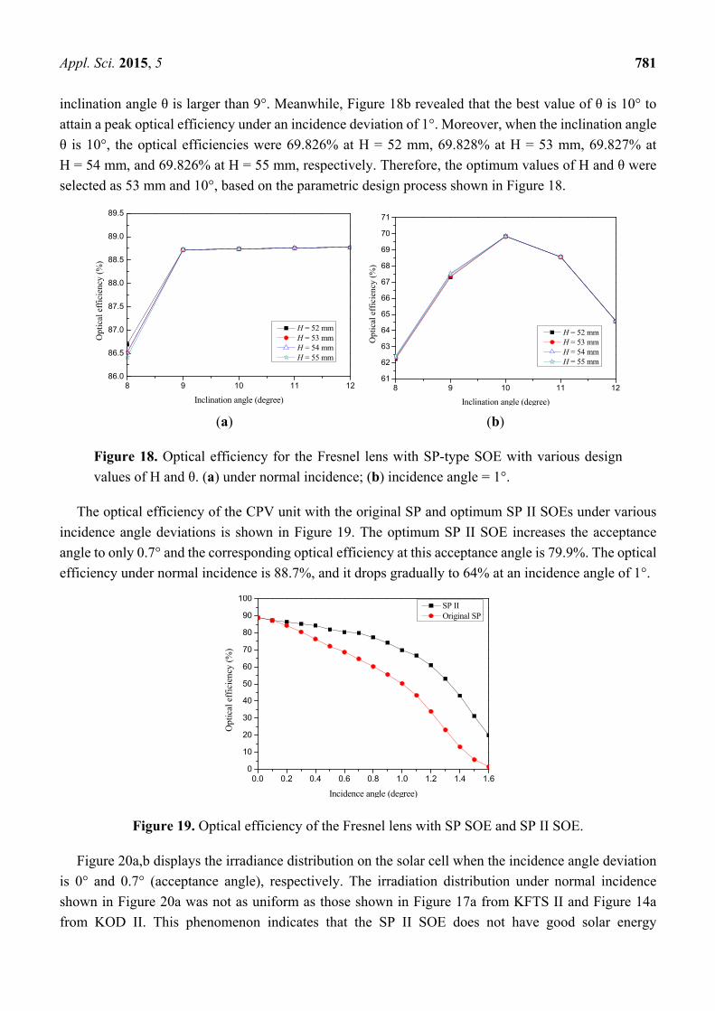
Figure 16 shows and compares the optical efficiency of the CPV unit with KFTS and KFTS II SOEs
under various incidence angles. The optimum KFTS II SOE extends the acceptance angle to 1.1° and
the corresponding optical efficiency at the acceptance angle is 76.9%. The optical efficiency under
normal incidence is 85%, and it decreases gradually to 0% at an incidence angle of 2°. Figure 17(a,b)
display the irradiance distribution on the solar cell when the incidence angle deviation is 0° and 1.1°
(acceptance angle), respectively. A very uniform distribution was obvious in Figure 17a, which indicates
that the KFTS II SOE exhibits good solar energy redistribution on the receiver under normal incidence.
Figure 16. Optical efficiency of the Fresnel lens with KFTS SOE and KFTS II SOE.
(a) (b)
Figure 17. Irradiance distribution on the receiver for the Fresnel lens with KFTS II-type
SOE (a) under normal incidence; (b) incidence angle = 1.1°.
3.3. SP II-Type SOE
The SP-type SOE is an open-truncated tetrahedral pyramid with specular walls, and its two basic
design parameters are height H and inclination angle θ of the walls, similar to the illustration shown in
Figure 5a. A parametric design process with various values of H and θ were performed to determine the
optimum SP-type SOE, designated as SP II.
Figure 18(a,b) shows the optical efficiency with various values of H and θ when the incidence
deviation are of 0° and 1°, respectively. As Figure 18a shows, the optical efficiency increases when the
0.0 0.2 0.4 0.6 0.8 1.0 1.2 1.4 1.6 1.8 2.005
101520253035404550556065707580859095
100 KFTS II Original KFTS
Opt
ical
eff
icie
ncy
(%)
Incidence angle (degree)
-0.5
0
0.5
-0.5
0
0.5
0
0.5
1
1.5
2
Position (mm)Position (mm)
Irra
dian
ce (
W/m
m2 )
0.62
0.64
0.66
0.68
0.7
0.72
0.74
0.76
0.78
0.8
0.82
-0.5
0
0.5
-0.5
0
0.5
0
0.5
1
1.5
2
Position (mm)Position (mm)
Irra
dian
ce (
W/m
m2 )
0.45
0.5
0.55
0.6
0.65
0.7
0.75
0.8
Appl. Sci. 2015, 5 781
inclination angle θ is larger than 9°. Meanwhile, Figure 18b revealed that the best value of θ is 10° to
attain a peak optical efficiency under an incidence deviation of 1°. Moreover, when the inclination angle
θ is 10°, the optical efficiencies were 69.826% at H = 52 mm, 69.828% at H = 53 mm, 69.827% at
H = 54 mm, and 69.826% at H = 55 mm, respectively. Therefore, the optimum values of H and θ were
selected as 53 mm and 10°, based on the parametric design process shown in Figure 18.
(a) (b)
Figure 18. Optical efficiency for the Fresnel lens with SP-type SOE with various design
values of H and θ. (a) under normal incidence; (b) incidence angle = 1°.
The optical efficiency of the CPV unit with the original SP and optimum SP II SOEs under various
incidence angle deviations is shown in Figure 19. The optimum SP II SOE increases the acceptance
angle to only 0.7° and the corresponding optical efficiency at this acceptance angle is 79.9%. The optical
efficiency under normal incidence is 88.7%, and it drops gradually to 64% at an incidence angle of 1°.
Figure 19. Optical efficiency of the Fresnel lens with SP SOE and SP II SOE.
Figure 20a,b displays the irradiance distribution on the solar cell when the incidence angle deviation
is 0° and 0.7° (acceptance angle), respectively. The irradiation distribution under normal incidence
shown in Figure 20a was not as uniform as those shown in Figure 17a from KFTS II and Figure 14a
from KOD II. This phenomenon indicates that the SP II SOE does not have good solar energy
8 9 10 11 1286.0
86.5
87.0
87.5
88.0
88.5
89.0
89.5
Opt
ical
eff
icie
ncy
(%)
Inclination angle (degree)
H = 52 mm H = 53 mm H = 54 mm H = 55 mm
8 9 10 11 1261
62
63
64
65
66
67
68
69
70
71
Opt
ical
eff
icie
ncy
(%)
Inclination angle (degree)
H = 52 mm H = 53 mm H = 54 mm H = 55 mm
0.0 0.2 0.4 0.6 0.8 1.0 1.2 1.4 1.60
10
20
30
40
50
60
70
80
90
100
Opt
ical
eff
icie
ncy
(%)
Incidence angle (degree)
SP II Original SP
Appl. Sci. 2015, 5 782
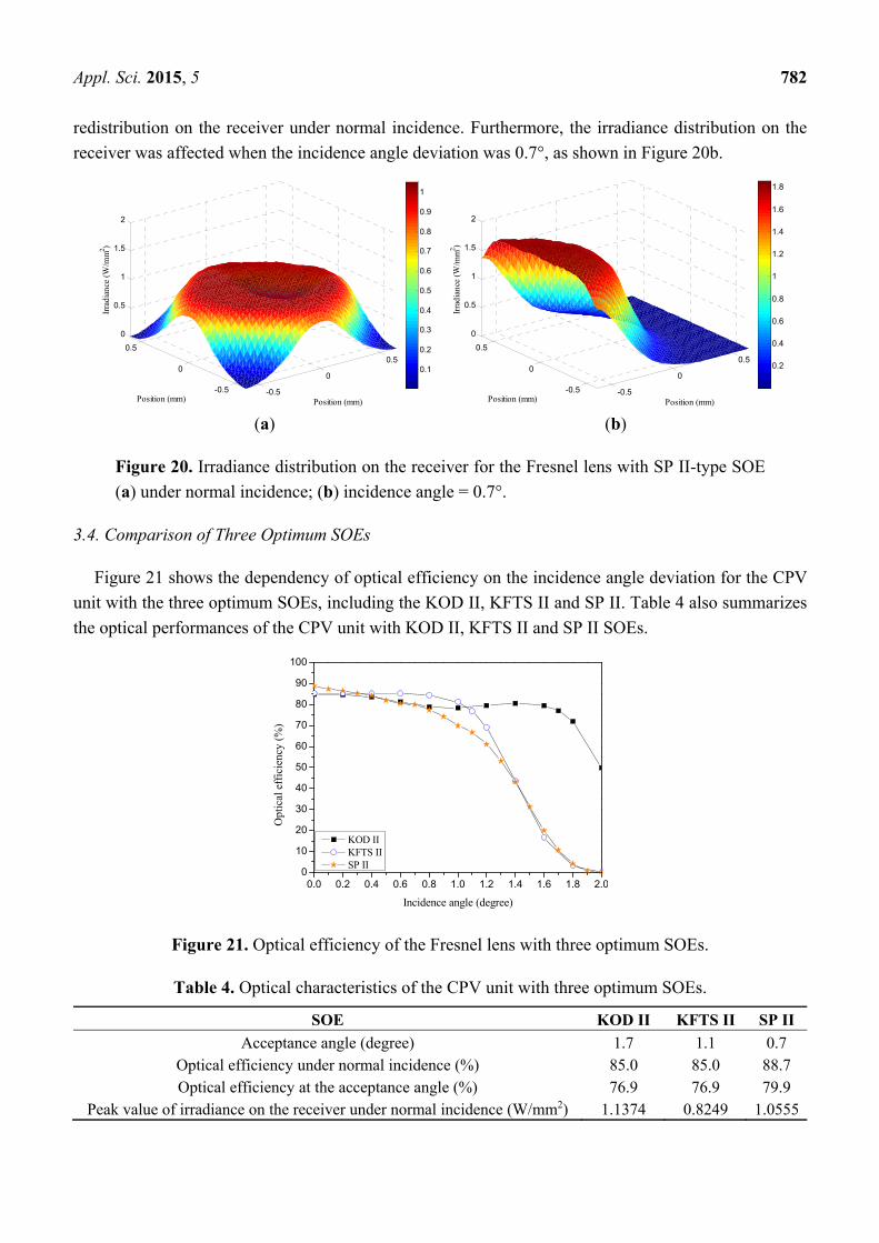
redistribution on the receiver under normal incidence. Furthermore, the irradiance distribution on the
receiver was affected when the incidence angle deviation was 0.7°, as shown in Figure 20b.
(a) (b)
Figure 20. Irradiance distribution on the receiver for the Fresnel lens with SP II-type SOE
(a) under normal incidence; (b) incidence angle = 0.7°.
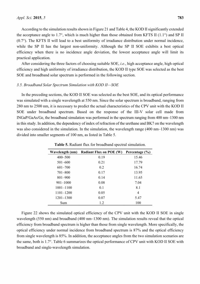
3.4. Comparison of Three Optimum SOEs
Figure 21 shows the dependency of optical efficiency on the incidence angle deviation for the CPV
unit with the three optimum SOEs, including the KOD II, KFTS II and SP II. Table 4 also summarizes
the optical performances of the CPV unit with KOD II, KFTS II and SP II SOEs.
Figure 21. Optical efficiency of the Fresnel lens with three optimum SOEs.
Table 4. Optical characteristics of the CPV unit with three optimum SOEs.
SOE KOD II KFTS II SP II
Acceptance angle (degree) 1.7 1.1 0.7 Optical efficiency under normal incidence (%) 85.0 85.0 88.7 Optical efficiency at the acceptance angle (%) 76.9 76.9 79.9
Peak value of irradiance on the receiver under normal incidence (W/mm2) 1.1374 0.8249 1.0555
-0.5
0
0.5
-0.5
0
0.5
0
0.5
1
1.5
2
Position (mm)Position (mm)
Irra
dian
ce (
W/m
m2 )
0.1
0.2
0.3
0.4
0.5
0.6
0.7
0.8
0.9
1
-0.5
0
0.5
-0.5
0
0.5
0
0.5
1
1.5
2
Position (mm)Position (mm)
Irra
dian
ce (
W/m
m2 )
0.2
0.4
0.6
0.8
1
1.2
1.4
1.6
1.8
0.0 0.2 0.4 0.6 0.8 1.0 1.2 1.4 1.6 1.8 2.00
10
20
30
40
50
60
70
80
90
100
Opt
ical
eff
icie
ncy
(%)
Incidence angle (degree)
KOD II KFTS II SP II
Appl. Sci. 2015, 5 783
According to the simulation results shown in Figure 21 and Table 4, the KOD II significantly extended
the acceptance angle to 1.7°, which is much higher than those obtained from KFTS II (1.1°) and SP II
(0.7°). The KFTS II will lead to a best uniformity of irradiance distribution under normal incidence,
while the SP II has the largest non-uniformity. Although the SP II SOE exhibits a best optical
efficiency when there is no incidence angle deviation, the lowest acceptance angle will limit its
practical application.
After considering the three factors of choosing suitable SOE, i.e., high acceptance angle, high optical
efficiency and high uniformity of irradiance distribution, the KOD II type SOE was selected as the best
SOE and broadband solar spectrum is performed in the following section.
3.5. Broadband Solar Spectrum Simulation with KOD II—SOE
In the preceding sections, the KOD II SOE was selected as the best SOE, and its optical performance
was simulated with a single wavelength at 550 nm. Since the solar spectrum is broadband, ranging from
280 nm to 2500 nm, it is necessary to predict the actual characteristics of the CPV unit with the KOD II
SOE under broadband spectrum. Based on the response of the III-V solar cell made from
INGaP/GaAs/Ge, the broadband simulation was performed in the spectrum ranging from 400 nm–1300 nm
in this study. In addition, the dependency of index of refraction of the urethane and BK7 on the wavelength
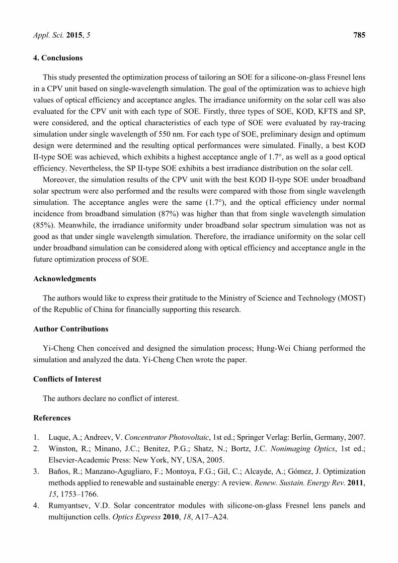
was also considered in the simulation. In the simulation, the wavelength range (400 nm–1300 nm) was
divided into smaller segments of 100 nm, as listed in Table 5.
Table 5. Radiant flux for broadband spectral simulation.
Wavelength (nm) Radiant Flux on POE (W) Percentage (%)
400–500 0.19 15.46 501–600 0.21 17.79 601–700 0.2 16.74 701–800 0.17 13.95 801–900 0.14 11.65
901–1000 0.08 7.04 1001–1100 0.1 8.1 1101–1200 0.05 4 1201–1300 0.07 5.47
Sum 1.2 100
Figure 22 shows the simulated optical efficiency of the CPV unit with the KOD II SOE in single
wavelength (550 nm) and broadband (400 nm–1300 nm). The simulation results reveal that the optical
efficiency from broadband spectrum is higher than those from single wavelength. More specifically, the
optical efficiency under normal incidence from broadband spectrum is 87% and the optical efficiency
from single wavelength is 85%. In addition, the acceptance angles from the two simulation scenarios are
the same, both is 1.7°. Table 6 summarizes the optical performance of CPV unit with KOD II SOE with
broadband and single-wavelength simulation.

Appl. Sci. 2015, 5 784
Figure 22. Optical efficiency of broadband (400 nm–1300 nm) and single wavelength
(550 nm) simulation.
Table 6. Comparison of optical performance of CPV unit with KOD II SOE with broadband
and single-wavelength simulation.
Optical Performance Broadband
(400 nm–1300 nm)
Single Wavelength
(550 nm)
Acceptance angle (degree) 1.7 1.7
Optical efficiency under normal incidence (%) 87 85
Optical efficiency at the acceptance angle (%) 79.2 76.9
Peak value of irradiance on the receiver under normal incidence (W/mm2) 0.9236 1.1374
Figure 23(a,b) show the irradiance distribution on the receiver from broadband simulation with KOD
II-type SOE when the incidence angle is 0° and 1.7°, respectively. By comparing Figure 23a and Figure
14a, it is found that the irradiance is more localized in the central region of the solar cell based on
broadband simulation. This phenomena results from the fact that the index of refraction of the Fresnel
lens is decreasing with an increase of wavelength. Therefore, the irradiance distribution on the solar cell
under broadband simulation was not as uniform as that under a single wavelength of 550nm. The
presented optimization process in this study was based on the simulation of single-wave length. In the
future, a further optimization can be conducted considering the broadband solar spectrum and the
response of specific solar cell.
(a) (b)
Figure 23. Irradiance distribution on the receiver from broadband simulation for the Fresnel
lens with KOD II-type SOE (a) under normal incidence; (b) incidence angle = 1.7°.
0.0 0.2 0.4 0.6 0.8 1.0 1.2 1.4 1.6 1.870
72
74
76
78
80
82
84
86
88
90
Opt
ical
eff
icie
ncy
(%)
Incidence angle (degree)
Single wavelength (550 nm) Broad band (400 nm-1300 nm)
-0.5
0
0.5
-0.5
0
0.5
0
0.5
1
1.5
2
Position (mm)Position (mm)
Irra
dian
ce (
W/m
m2 )
0.2
0.3
0.4
0.5
0.6
0.7
0.8
0.9
-0.5
0
0.5
-0.5
0
0.5
0
0.5
1
1.5
2
Position (mm)Position (mm)
Irra
dian
ce (
W/m
m2 )
0.1
0.2
0.3
0.4
0.5
0.6
0.7
0.8
0.9
Appl. Sci. 2015, 5 785
4. Conclusions
This study presented the optimization process of tailoring an SOE for a silicone-on-glass Fresnel lens
in a CPV unit based on single-wavelength simulation. The goal of the optimization was to achieve high
values of optical efficiency and acceptance angles. The irradiance uniformity on the solar cell was also
evaluated for the CPV unit with each type of SOE. Firstly, three types of SOE, KOD, KFTS and SP,
were considered, and the optical characteristics of each type of SOE were evaluated by ray-tracing
simulation under single wavelength of 550 nm. For each type of SOE, preliminary design and optimum
design were determined and the resulting optical performances were simulated. Finally, a best KOD
II-type SOE was achieved, which exhibits a highest acceptance angle of 1.7°, as well as a good optical
efficiency. Nevertheless, the SP II-type SOE exhibits a best irradiance distribution on the solar cell.
Moreover, the simulation results of the CPV unit with the best KOD II-type SOE under broadband
solar spectrum were also performed and the results were compared with those from single wavelength
simulation. The acceptance angles were the same (1.7°), and the optical efficiency under normal
incidence from broadband simulation (87%) was higher than that from single wavelength simulation
(85%). Meanwhile, the irradiance uniformity under broadband solar spectrum simulation was not as
good as that under single wavelength simulation. Therefore, the irradiance uniformity on the solar cell
under broadband simulation can be considered along with optical efficiency and acceptance angle in the
future optimization process of SOE.
Acknowledgments
The authors would like to express their gratitude to the Ministry of Science and Technology (MOST)
of the Republic of China for financially supporting this research.
Author Contributions
Yi-Cheng Chen conceived and designed the simulation process; Hung-Wei Chiang performed the
simulation and analyzed the data. Yi-Cheng Chen wrote the paper.
Conflicts of Interest
The authors declare no conflict of interest.
References
1. Luque, A.; Andreev, V. Concentrator Photovoltaic, 1st ed.; Springer Verlag: Berlin, Germany, 2007.
2. Winston, R.; Minano, J.C.; Benitez, P.G.; Shatz, N.; Bortz, J.C. Nonimaging Optics, 1st ed.;
Elsevier-Academic Press: New York, NY, USA, 2005.
3. Baños, R.; Manzano-Agugliaro, F.; Montoya, F.G.; Gil, C.; Alcayde, A.; Gómez, J. Optimization
methods applied to renewable and sustainable energy: A review. Renew. Sustain. Energy Rev. 2011,
15, 1753–1766.
4. Rumyantsev, V.D. Solar concentrator modules with silicone-on-glass Fresnel lens panels and
multijunction cells. Optics Express 2010, 18, A17–A24.

Appl. Sci. 2015, 5 786
5. Duerr, F.; Meuret, Y.; Thienpont, H. Miniaturization of Fresnel lenses for solar concentration:
A quantitative investigation. Appl. Optics 2010, 49, 2339–2346.
6. Ryu, K.; Rhee, J.-G.; Park, K.-M.; Kim, J. Concept and design of modular Fresnel lenses for
concentration solar PV system. Sol. Energy 2006, 80, 1580–1587.
7. Huang, J.-H.; Fei, W.-C.; Hsu, W.-C.; Tsai, J.-C. Solar concentrator constructed with a circular
prism array. Appl. Optics 2010, 49, 4472–4478.
8. Andreev, V.M.; Grilikhes, V.A.; Soluyanov, A.A.; Vlasova, E.V.; Shvarts, M.Z. Optimization of
the secondary optics for photovoltaic units with Fresnel lenses. In Proceedings of the 23th European
Photovoltaic Solar Energy Conference, Valencia, Spain, 1–5 September 2008; pp. 126–131.
9. Victoria, M.; Doḿinguez, C.; Anton, I.; Sala, G. Comparative analysis of different secondary
optical elements for aspheric primary lenses. Optics Express 2009, 17, 6487–6492.
10. Fu, L.; Leutz, R.; Annen, H.P. Secondary optics for Fresnel lens solar concentrators. In Nonimaging
Optics: Efficient Design for Illumination and Solar Concentration VII. Proceedings of SPIE 7785,
San Diego, CA, USA, 1 August 2010; pp. 778509.1–778509.6.
11. Zhuang, Z.; Yu, F.; Optimization design of hybrid Fresnel-based concentrator for generating
uniformity irradiance with the broad solar spectrum. Optics Laser Technol. 2014, 60, 27–33.
12. Buljan, M.; Miñano, J.C.; Benítez, P.; Mohedano, R.; Chaves, J. Improving performances of Fresnel
CPV systems: Fresnel-RXI Köhler concentrator. Optics Express 2014, 22, A205–A210.
13. Lv, H.; Sheng, F.; Dai, J.; Liu, W.; Cheng, C.; Zhang, J. Temperature-dependent model of
concentrator photovoltaic modules combining optical elements and III-V multi-junction solar cells.
Sol. Energy 2015, 112, 351–360.
14. Shvarts, M.Z.; Andreev, V.M.; Gorohov, V.S.; Grilikhes, V.A.; Petrenko, A.E.; Soluyanov, A.A.;
Timoshina, N.H. Flat-plate Fresnel lenses with improved concentrating capabilities: Designing,
manufacturing and test. In Proceedings of the 33th Photovoltaic Specialists Conference, San Diego,
CA, USA, 11–16 May 2008; pp. 1–6.
15. Chaves, J. Introduction to Nonimaging Optics, 1st ed.; CRC Press: Boca Raton, FL, USA, 2008.
© 2015 by the authors; licensee MDPI, Basel, Switzerland. This article is an open access article
distributed under the terms and conditions of the Creative Commons Attribution license
(http://creativecommons.org/licenses/by/4.0/).