
2015 DSCC
16
Efficient Aeroelastic Energy Harvesting from HVAC Ducts Xiaokun Ma Christopher D. Rahn Department of Mechanical and Nuclear Engineering The Pennsylvania State University October 28 th 2015 1
-
Upload
xiaokun-ma -
Category
Documents
-
view
253 -
download
0
Transcript of 2015 DSCC

Efficient Aeroelastic Energy Harvestingfrom HVAC Ducts
Xiaokun MaChristopher D. Rahn
Department of Mechanical and Nuclear EngineeringThe Pennsylvania State University
October 28th 2015
1

Galloping energy harvester with equilateral triangle cross-section tip body(Sirohi, 2011, Journal of Intelligent Material Systems and Structures)
Aeroelastic Energy Harvesters
Vortex shedding induced energy harvester(Weinstein, 2012, Smart Materials and Structures)
Flapping-leaf generator(Li, 2009, SMASIS)
Galloping energy harvester with rectangular cross-section tip body(Zhao, 2012, SMASIS)
• Vortex induced vibration
• Galloping
2

Flow-induced self-excited generator(Bibo, 2011, Journal of Intelligent Material Systems and Structures)
Aeroelastic Energy Harvesters
Piezoaeroelastic airfoil(Erturk, 2010, Applied Physics Letters)
• Flutter • Harmonica inspired device
Alternative beam geometries(Roundy, 2005, Pervasive Computing)
• Strain distribution
3
• Device Design and Model
• Stability Analysis
• Performance Comparison
• Conclusions and Future Work
Outline
4

• Device design Mounted to a HVAC duct wall Air flow scoop above, and electronics and connectors underneath PVDF unimorph pinned at the top and bottom using compliant hinges Transverse vibration opens and closes the air gap Self-excited above a critical flow speed
• Model parameters PVDF unimorph (from Measurement Specialties, Inc.): Chamber dimension: Inflow speed:
Design
5

• Transversal beam dynamics
• Electrical circuit equation
Model
Stretching effect for pinned-pinned beam
Strain due to stretching Strain due to bending
6

• Pressure dynamics Bernoulli equation (inviscid, irrotational, laminar, and steady flow):
Area of the aperture:
Continuity equation (compressible flow):
Pressure dynamics:
Model
A single-mode reduced-order model is sufficient to approximate the local dynamics(Bibo, 2011, Journal of Intelligent Material Systems and Structures)
𝑤 (𝑥 , 𝑡 )=∅ (𝑥 )𝑞 (𝑡 )=sin ( 𝜋𝐿 𝑥 )𝑞 (𝑡 )
Nonlinear state space model
7
Beam dynamicsElectrical circuit
equationPressure dynamics

• Device Design and Model
• Stability Analysis
• Performance Comparison
• Conclusions and Future Work
Outline
8

• Linearized model: • Design parameters: air gap width , inflow speed
Stability Analysis
Cantilever Pinned-pinned beam
𝑣0=3𝑚/ 𝑠
𝑊 𝑔=2𝑚𝑚
9
Limit cycle frequency
126.1
Limit cycle frequency
2234
Stability Analysis
CantileverPinned-pinned beam
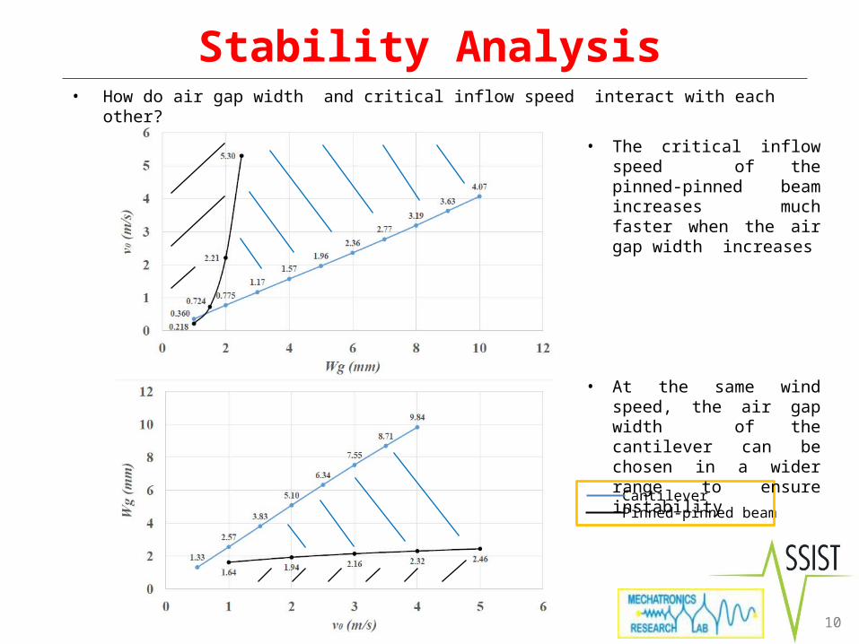
• The critical inflow speed of the pinned-pinned beam increases much faster when the air gap width increases
• At the same wind speed, the air gap width of the cantilever can be chosen in a wider range to ensure instability
10
• How do air gap width and critical inflow speed interact with each other?

• Device Design and Model
• Stability Analysis
• Performance Comparison
• Conclusions and Future Work
Outline
11

Performance Comparison
Displacement Maximum Strain Power
Cantilever
Pinned-pinned beam
() () () (1% strain)
()
Cantilever 126.1 912 2.13% 1.72 0.808
Pinned-Pinned Beam 2234 51.5 0.179% 0.658 3.68
4x higher average power 12
• Air gap width , inflow speed
11x smaller maximum strain

Tunable Axial Stiffness
• The beam midpoint vibration amplitude increases but the limit cycle frequency decreases when the axial stiffness is reduced
• The average power increases and exceeds of the cantilever when
13
• What if we can use an axially flexible pinned-pinned boundary condition?
𝒇(𝑯𝒛) 𝑨𝒘(𝒎𝒎)
𝑷𝒂𝒗𝒆(𝒎𝑾)
• Device Design and Model
• Stability Analysis
• Performance Comparison
• Conclusions and Future Work
Outline
14

Conclusions and Future Work• Conclusions
The stability analysis can serve as a design guideline to choose crucial parameters Compared with the cantilever design, the pinned-pinned beam has a much higher limit cycle
frequency and more efficient mode shape The maximum strain in the pinned-pinned beam is 11 times smaller than the cantilever The pinned-pinned beam generates 4 times more average power than the cantilever with the
same maximum strain The tunable axial stiffness design generates higher power output
• Future Work Experimental validation of the model Investigate the tunable axial stiffness design and fabrication
15

Thank you!16
Acknowledgment• This work was supported by the National Science Foundation ASSIST Nanosystems ERC
under Award Number EEC-1160483


